30GX NEE + QM 119 - Acare - Klimatizace, chlazení a … · · 2010-03-30Control of the...
12
30GX NEE + QM 119 Nominal cooling capacity 258-911 kW 50 Hz The 30GX units are air-cooled chillers, designed from the ground up to meet the needs of today and tomorrow: - ecological HFC-134a refrigerant - screw compressors - compact footprint - mechanically cleanable evaporator All units are equipped with PRO-DIALOG Plus control to optmize the efficiency of the refrigerant circuit, and with the revolutionary FLYING BIRD fan with rotating shroud. This innovative fan considerably reduces the air circulation noise and contributes to quiet unit operation. It is made of fully recyclable composite materials. The high outdoor temperature versions are equipped with condensers with non-slatted double-wavy fins to reduce the fouling effect (sand, dust etc.), and with ventilated control boxes to keep the electrical components at the right tempe- rature. Features Quality design and construction make the 30GX unit the preferred choice. ■ Non-controlled, ozone-friendly HFC-134a refrigerant. HCF-134a is a proven, non-toxic, non-flammable refriger- ant which will have the highest usage of any new refriger- ant. ■ Medium-pressure refrigerant HFC-134a minimizes stress on the compressors and ensures their long operating life. ■ The 30GX units are equipped with screw compressors and with shrouded axial Flying Bird fans for extremely quiet operation and low-vibration levels. ■ The 30GX units exceed the efficiency level of average industry standards for both full- and part-load operation, saving on operating costs, through lower electrical costs. ■ The 30GX control is fully automatic. The leaving water temperature is continuously monitored to detect load and flow changes. This combination provides the most precise temperature control available. ■ Two independent refrigerant circuits - the second one takes over automatically, when the first one malfunctions, main- taining partial cooling under all circumstances. ■ Easy installation - the 30GX chillers are supplied with a full refrigerant charge, and conveniently located power supply and water inlet and outlet connections. ■ Auto-diagnostics - quick display of the machine status. ■ Multiple compressor concept for optimized part-load effi- ciency and minimized starting current. ■ Series star/delta starter, limiting the start-up current on 30GX 082-182 units. Easy installation ■ The 30GX has a compact design that is up to 50% smaller than current chillers. The 30GX is supplied as a complete package for easy installation. There are no extra controls, timers, starters or other items to install. ■ 30GX units have a single power point and one main discon- nect/isolator switch for sizes 30GX 082 to 182, and one power point and one main disconnect/isolator switch per circuit for sizes 30GX 207 to 358. The hydraulic connections are simple and facilitated by the use of Victaulic connections for the evaporator. Air-Cooled Screw Compressor Liquid Chillers High-efficiency, high outdoor temperature version GLOBAL CHILLER
Transcript of 30GX NEE + QM 119 - Acare - Klimatizace, chlazení a … · · 2010-03-30Control of the...

30GX NEE + QM 119Nominal cooling capacity 258-911 kW
50 Hz
Air-Cooled Screw Compressor Liquid ChillersHigh-efficiency, high outdoor temperature version
GLOBAL CHILLER
The 30GX units are air-cooled chillers, designed from the ground up to meet the needs of today and tomorrow:- ecological HFC-134a refrigerant- screw compressors- compact footprint- mechanically cleanable evaporatorAll units are equipped with PRO-DIALOG Plus control to optmize the efficiency of the refrigerant circuit, and with the revolutionary FLYING BIRD fan with rotating shroud. This innovative fan considerably reduces the air circulation noise and contributes to quiet unit operation. It is made of fully recyclable composite materials.The high outdoor temperature versions are equipped with condensers with non-slatted double-wavy fins to reduce the fouling effect (sand, dust etc.), and with ventilated control boxes to keep the electrical components at the right tempe-rature.
FeaturesQuality design and construction make the 30GX unit the preferred choice.
■ Non-controlled, ozone-friendly HFC-134a refrigerant. HCF-134a is a proven, non-toxic, non-flammable refriger-ant which will have the highest usage of any new refriger-ant.
■ Medium-pressure refrigerant HFC-134a minimizes stress on the compressors and ensures their long operating life.
■ The 30GX units are equipped with screw compressors and with shrouded axial Flying Bird fans for extremely quiet operation and low-vibration levels.
■ The 30GX units exceed the efficiency level of average industry standards for both full- and part-load operation, saving on operating costs, through lower electrical costs.
■ The 30GX control is fully automatic. The leaving water temperature is continuously monitored to detect load and flow changes. This combination provides the most precise temperature control available.
■ Two independent refrigerant circuits - the second one takes over automatically, when the first one malfunctions, main-taining partial cooling under all circumstances.
■ Easy installation - the 30GX chillers are supplied with a full refrigerant charge, and conveniently located power supply and water inlet and outlet connections.
■ Auto-diagnostics - quick display of the machine status.■ Multiple compressor concept for optimized part-load effi-
ciency and minimized starting current.■ Series star/delta starter, limiting the start-up current on
30GX 082-182 units.
Easy installation■ The 30GX has a compact design that is up to 50% smaller
than current chillers. The 30GX is supplied as a complete package for easy installation. There are no extra controls, timers, starters or other items to install.
■ 30GX units have a single power point and one main discon-nect/isolator switch for sizes 30GX 082 to 182, and one power point and one main disconnect/isolator switch per circuit for sizes 30GX 207 to 358.The hydraulic connections are simple and facilitated by the use of Victaulic connections for the evaporator.

Simple to service■ Mechanically-cleanable evaporator■ Twin-screw compressors which require minimum routine
service or maintenance.■ Easily accessed suction and discharge pressure and tempe-
rature information via a display module.
PRO-DIALOG Plus controlPRO-DIALOG Plus is an advanced numeric control system that combines intelligence with great operating simplicity.
PRO-DIALOG Plus ensures intelligent leaving water temperature control and optimises energy require-ments.■ The PID control algorithm with permanent compensation
for the difference between the heat exchanger entering and leaving temperature, anticipates load variations, guarantees leaving water temperature stability and prevents unneces-sary compressor cycling.
■ The long-stroke electronic expansion valves (EXV), together with refrigerant level control via heat exchange in the evaporator, allows a significant energy efficiency improvement at part load conditions, and faultless chiller operation in a wider temperature range.
■ Adjustable ramp loading, according to the inertia of the application, avoids load increases that are too fast and too frequent, increasing unit life and limiting power consump-tion peaks.
■ Several capacity loading possibilities ensure improved start-up at low outdoor air temperature, and permit use of one of the refrigerant circuits as a back-up circuit.
PRO-DIALOG Plus ensures preventive protection and enhances chiller reliability.■ Equalisation of compressor operating hours■ No capillary tubes or pressostats (except as safety device)■ PRO-DIALOG Plus monitors all chiller safety parameters.
The fault history function and the fault codes facilitate immediate location of faults and in certain cases the condi-tions causing the alarm. Prognostic and preventive mainte-nance functions (incorrect water loop, oil filter dirty etc.) permit anticipation of possible problems.
PRO-DIALOG Plus offers extended communications capabilities■ Clear and easy-to-understand operator interface. The LEDs,
numeric displays and touch keys are well-positioned on the schematic chiller diagram. The user immediately knows all operating parameters: pressures, temperatures, operating hours, etc.
■ The extensive chiller remote control capabilities (wired connection) allow integration into building monitoring sys-tems (see Technical Description)
■ RS485 series port for connection to the Carrier Comfort Network (CCN) or any other monitoring system (accessory communications interface with open protocol allows trans-fer of almost 40 parameters).
■ Parallel piloting of two units as standard, or of several units with Flotronic System Manager (FSM) and Chiller System Manager (CSM III) options.
■ The control permits:- Control in master/slave configuration of two units operat-
ing in parallel.- Programming of operating time schedules (up to 8 peri-
ods per week)- Programming of operating time schedules for the second
set point (up to 8 periods per week)- Definition of operating time period with demand limit.- Integration of the unit into a building monitoring system
(BMS): serial port RS 485.■ Control of the customer’s water pump (dual pump with
automatic configurable change-over).■ Control at the second set point (example: room unoccu-
pied).Set point reset as a function of the air temperature or the difference between entering and leaving water temperature.
2
Options and accessoriesOption Accessory
Condenser anti-corrosion treatment for marine applications X*
Condenser anti-corrosion treatment for heavy-duty rural, urban and industrial applications X*
Protection grilles X X
High and low pressure manometers X
Compressor suction valve X
Evaporator with one pass less X
Evaporator maximum water-side operating pressure of 21 bar X
Unit with very low noise level (option 15A - field-installed acoustic louvre kit) X*
RS485 communications interface with open protocol X
Compressor soft start (30GX 207-328) - electronic starter X
Tropicalized control box X
Reversed evaporator water inlet/outlet X
Available fan pressure 150 Pa X
Kit with Victaulic collars, connection flanges and counter-flanges (evaporator inlet and outlet) X
Kit with Victaulic collars and 150 mm welded pipe joints (evaporator inlet and outlet) X
Evaporator water pump starter X
* Air entering high temperature limit modified – see electronic selection program

Carrier´s environmental leadership
PRO-DIALOG Plus operator interface
The 30GX is 20-50% smaller than the chillers it replacesCarrier POWER3 twin-screw compressor
Low-noise FLYING BIRD axial fan with rotating shroud

Physical data30GX NEE + QM119 082 112 122 132 152 162 207 227 247 298 328Nominal cooling capacity* kW 258 314 342 368 418 444 601 621 677 827 912
Cooling capacity** kW 214 266 289 311 358 380 509 525 577 702 783
Operating weight kg 3208 3521 3535 3549 3995 4011 5809 5824 6467 7738 8235
Refrigerant charge*** HFC-134a
Circuit A kg 57 59 64 61 81 81 139 139 174 183 176Circuit B kg 58 58 62 66 76 82 91 91 98 163 177
Compressors Semi-hermetic, twin-screw POWER3
Quantity - Circuit A 1 1 1 1 1 1 2 2 2 2 2Quantity - Circuit B 1 1 1 1 1 1 1 1 1 2 2Capacity control PRO-DIALOG Plus controlNo. of control steps 6 6 6 6 6 6 8 8 8 10 10Minimum step capacity % 19 21 19 21 19 21 16 14 14 9 10
Evaporator Shell and tube with internally finned copper tubesNet water volume l 50 69 69 73 65 65 126 126 155 191 208Water connections Victaulic connectionsInlet/outlet in 4 5 5 5 5 5 6 6 6 8 8Drain and vent (NPT) in 3/8NPTMax. water side operating pressure kPa 1000 1000 1000 1000 1000 1000 1000 1000 1000 1000 1000
Condensers Copper tubes, aluminium finsCondenser fans Axial FLYING BIRD fan with a rotating shroudQuantity 4 6 6 6 8 8 10 10 12 14 16Fan speed r/s 15.8 15.8 15.8 15.8 15.8 15.8 15.8 15.8 15.8 15.8 15.8
Total air flow l/s 21380 32070 32070 32070 42760 42760 53450 53450 64140 74830 85520
* Based on an evaporator entering/leaving water temperature of 12.5°C and 7°C and an outdoor air temperature of 35°C.** Based on an evaporator entering/leaving water temperature of 12.2°C and 6.7°C and an outdoor air temperature of 46.1°C.
*** The weights shown are guidelines only. For the unit refrigerant charge please refer to the unit nameplate.
Electrical data
* Based on an evaporator entering/leaving water temperature of 12.5°C and 7°C and an outdoor air temperature of 35°C. Unit power input (compressors, fans, control).** Based on an evaporator entering/leaving water temperature of 12.2°C and 6.7°C and an outdoor air temperature of 46.1°C.
*** Maximum power input, compressor and fans, at unit operating limits and a nominal voltage of 400 V**** Maximum unit operating current at maximum unit power input.
† Maximum instantaneous starting current (maximum operating current of the smallest compressor(s) + fan current + locked rotor current or reduced starting current of the largest compressor).Fan electrical data = power input 2.4 kW and current draw 5.5 A per fan
†† Current and power inputs not included in the values aboveN/A Not applicable
30GX NEE + QM119 082 112 122 132 152 162 207 227 247 298 328Power circuitNominal power supply V-ph-Hz 400-3-50Voltage range V 360-440
Control circuit supply The control circuit is supplied via the factory-installed transformer
Nominal power input - standard unit* kW 85 105 117 129 143 157 203 220 234 288 318
Power input** kW 98 121 134 147 163 179 233 252 267 328 363
Nominal current drawn* A 144 178 199 219 240 263 341 369 393 483 534
Maximum power input*** kW 118 150 164 177 199 216 285 302 323 393 431Circuit A kW 59 75 89 89 108 108 177 194 216 216 216Circuit B kW 59 75 75 89 91 108 108 108 108 177 216
Maximum current drawn (Un - 10%)**** A 226 287 311 334 377 407 539 569 611 741 813Circuit A A - - - - - - 334 364 407 407 407Circuit B A - - - - - - 204 204 204 334 407
Maximum current drawn (Un****) A 203 258 280 301 339 366 485 512 550 667 732Circuit A A - - - - - - 301 328 366 366 366Circuit B A - - - - - - 184 184 184 301 366
Maximum starting current, standard unit (Un)† A 303 371 415 437 481 508 1206 1308 1348 1466 1532
Circuit A A - - - - - - 1022 1126 1163 1163 1163Circuit B A - - - - - - 982 982 982 1022 1163
Max. starting current/max. current draw ratio, unit 1,49 1,44 1,48 1,45 1,42 1,39 2.49 2.55 2.45 2.20 2.09Max. starting current/max. current draw ratio, circuit A - - - - - - 3.40 3.43 3.18 3.18 3.18Max. starting current/max. current draw ratio, circuit B - - - - - - 5.34 5.34 5.34 3.40 3.18
Max. starting current - reduced current start (Un) † A std. std. std. std. std. std. 827 922 960 1078 1141Circuit A std. std. std. std. std. std. 646 741 778 778 778Circuit B std. std. std. std. std. std. 457 457 457 646 778
Max.starting current - red. current start/max. current draw ratio, unit std. std. std. std. std. std. 1.71 1.80 1.75 1.62 1.56Circuit A std. std. std. std. std. std. 2.15 1.52 2.13 2.13 2.13Circuit B std. std. std. std. std. std. 2.48 2.15 2.48 2.15 2.13
Three-phase short-circuit holding current kA 25 25 25 25 25 25 N/A N/A N/A N/A N/ACircuit A - - - - - - 25 25 25 25 25Circuit B - - - - - - 25 25 25 25 25
Standby capacity, unit or circuit A††
for evaporator water pump connections kW 4 5.5 5.5 5.5 7.5 7.5 7.5 9 9 15 15and for heat reclaim condenser pump kW 3 4 4 5.5 5.5 5.5 5.5 7.5 7.5 9 9

Electrical data notes 30GX NEE units:
• 30GX NEE 082-182 units have a single power connection point; 30GX NEE 207-358 NEE units have two connection points.
• The control box includes the following standard features:- A main disconnect switch for two-compressor units and a main
disconnect switch per circuit for three- or four-compressor units, motor starting and protection devices for each compressor and the fan(s)
- Control devices
• Electrical reserves:Circuit A has disconnect switches and branch sections, designed to supply the evaporator pump power input within the limits specified in the electrical data table.
• Field connections:All connections to the system and the electrical installations must be in full accordance with all applicable local codes.The Carrier 30GX NEE units are designed and built to ensure conformance with these codes.
• Installation and environmentThe recommendations of standard IEC 60 204-1 (standards issued by the International Electrotechnical Commission) are accepted as compliance with the requirements of the installation directives.The recommendations of standard IEC 60 204-1 (machine safety - electrical machine components - part 1: general regulations) are specifically taken into account, when designing the electrical equipment.Annex B of IEC 60204-1 describes the electrical characteristics used for the operation of the machines.
1. The unit environmental operating conditions(1) are specified below:- outdoor installation*- ambient temperature range: +5°C to +52°C- altitude: < 2000 m- presence of hard solids: significant dust present**- presence of corrosive and polluting substances***: negligible- vibration and shock: negligible- minimum competence level of personnel: instructed personnel****
Operating limitsEvaporator water flow rates
30GX NEE Minimum flow rate, l/s Maximum flow rate, l/s082 5.2 20.8
112-132 7.4 29.6
152-162 9.4 37.8
207-227 14.1 56.3
247 16.3 65.2
298 20.9 83.7
328 23.0 91.9
Note:The 30GX NEE units operate at a minimum ambient temperature of +5°C.
(1) The required protection level for this class is IP53BW†. All 30GX NEE units are protected to IP54CW† (electrical compartment protected against intrusion of hard solids or liquid splashes) and fulfil this protection condition.
2. Power supply frequency variation: ± 2 Hz.3. The neutral (N) conductor must not be connected directly to the unit (if
necessary use a transformer).4. Overcurrent protection of the power supply conductors is not provided
with the unit.5. The factory-installed disconnect switch(es)/circuit breaker(s) is (are) of a
type suitable for power interruption in accordance with IEC 60947-3.6. The units are designed for connection to TN networks (IEC 60364). For
IT networks the earth connection must not be at the network earth. Provide a local earth, consult competent local organisations to complete the electrical installation.
NOTE: If particular aspects of an actual installation do not conform to the conditions described above, or if there are other conditions which should be considered, always contact your local Carrier representative.
Notes:* The environmental classification is described in standard IEC 60721.
** The control boxes are equipped with filters and cooling fans.During operation the maintenance programme must take into account the dust in the environment.
*** In case of condensation in the control box, ensure tropicalisation of the control boxes (option 22).
**** Trained personnel: Personnel trained by a specialist, to ensure that he/she avoids any possible danger and risk in using electricity (IEC 60364 BA4 – classification of competence of personnel)
† Corresponds to IEC 60529 (IP codes correspond to the protection degree of the unit enclosure).
‡ IEC 60947-3 (low-capacity control and regulation units – Part 3: for a unit, associated disconnect switches, circuit breakers, disconnect buttons and fuses).

22
97
30GX - 08230GX - 11230GX - 12230GX - 132
30GX - 15230GX - 16230GX - 182
A
5 0 05 0 0
18
30
1
1 1
1
22
18
30
22
54
B
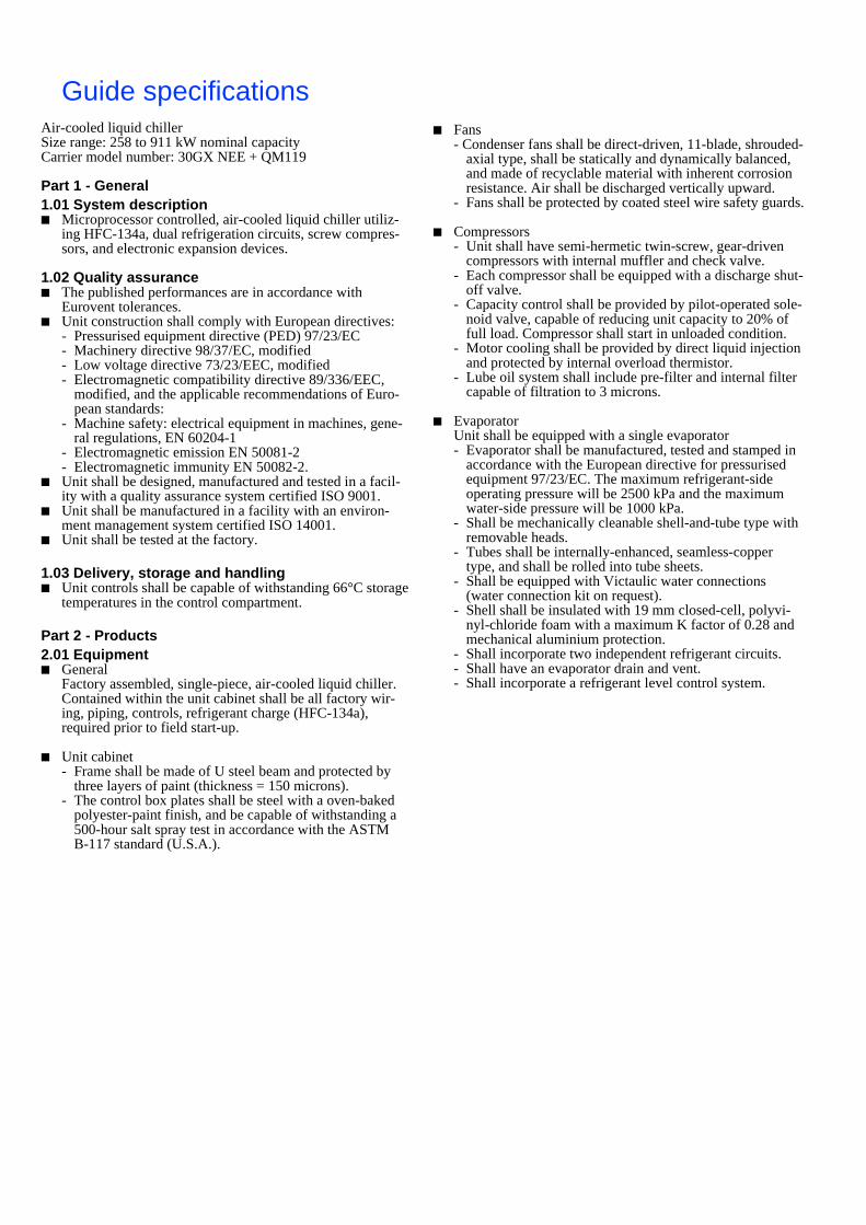
Dimensions/clearances30GX NEE 082-162
30GX NEE A B082 2967 1900
112-122-132 3425 1700
152-162 4340 2400
Do not obstruct

Do not obstruct
Legend:
All dimensions are given in mm.
Required clearances for maintenance
Recommended space for tube removal, space can be either on the right or the left hand side.
Water outlet
Water inlet
Air outlet, do not obstruct
Power supply
NOTE: For a specific installation, consult the certified dimensional drawings, available on request.
1
2
Dimensions/clearances30GX NEE 207-328
30GX NEE A B207-227 5994 2850
247 6909 2850
298 7824 2050
328 8739 1150
Do not obstruct
1
2
1
2
11
500500
1830
1830
B
2297
A
2254

Cooling capacities 30GX NEE + QM11930GX QM119
Condenser entering air temperature, °C
LWT 35 40 46 50 52
CAP COMP UNIT COOL CAP COMP UNIT COOL CAP COMP UNIT COOL CAP COMP UNIT COOL CAP COMP UNIT COOL
°C kW kW kW l/s kPa kW kW kW l/s kPa kW kW kW l/s kPa kW kW kW l/s kPa kW kW kW l/s kPa
082 5 242 73 83 10.5 34 224 79 88 9.75 29 203 86 96 8.82 24 188 91 101 8.18 21 181 94 103 7.85 19
112 292 88 102 12.7 27 273 95 109 11.9 24 250 103 118 10.9 20 235 110 124 10.2 18 227 113 127 9.86 17
122 319 99 113 13.8 31 298 106 120 12.9 28 272 116 130 11.8 23 255 123 137 11.1 21 247 126 141 10.7 19
132 344 110 125 14.9 32 321 118 133 14 28 294 129 143 12.8 24 276 137 151 12 21 267 141 155 11.6 20
152 388 119 138 16.9 26 365 128 147 15.8 23 336 139 158 14.6 19 317 148 167 13.8 17 308 152 171 13.4 16
162 413 133 152 17.9 29 388 142 162 16.9 25 357 155 174 15.5 22 337 164 184 14.6 19 327 169 188 14.2 18
207 561 173 197 24.4 31 524 186 210 22.8 27 480 202 226 20.9 23 450 215 239 19.6 20 435 221 245 18.9 19
227 581 189 213 25.2 33 543 203 227 23.6 29 496 221 245 21.6 24 465 234 258 20.2 22 449 241 265 19.5 20
247 630 198 226 27.4 28 591 212 241 25.7 25 544 231 259 23.6 21 512 245 273 22.2 19 495 252 281 21.5 18
298 772 245 278 33.5 26 723 262 296 31.4 23 664 285 319 28.8 20 623 302 336 27.1 17 602 311 345 26.2 16
328 846 269 308 36.8 26 796 288 327 34.6 23 736 314 352 31.9 20 696 333 371 30.2 18 676 343 381 29.3 17
082 6 250 75 84 10.8 36 232 80 90 10.1 31 210 87 97 9.11 26 195 92 102 8.45 22 187 95 105 8.11 21
112 303 90 104 13.2 29 284 96 111 12.3 25 260 105 119 11.3 21 244 111 126 10.6 19 236 115 129 10.2 18
122 330 101 115 14.3 34 308 108 122 13.4 30 282 118 132 12.3 25 265 125 139 11.5 22 256 128 143 11.1 21
132 356 112 127 15.5 34 333 120 135 14.4 30 304 131 145 13.2 25 285 139 153 12.4 22 276 143 157 12 21
152 403 121 141 17.5 27 379 130 149 16.4 24 349 142 161 15.2 21 329 150 169 14.3 19 319 155 174 13.9 18
162 429 135 155 18.6 31 402 145 164 17.5 27 371 158 177 16.1 23 350 167 186 15.2 21 339 172 191 14.7 20
207 581 176 200 25.2 33 543 189 213 23.6 29 498 206 230 21.6 25 467 218 242 20.3 22 451 225 249 19.6 20
227 601 193 217 26.1 35 562 207 231 24.4 31 513 225 249 22.3 26 481 238 262 20.9 23 465 245 269 20.2 21
247 654 201 230 28.4 30 613 215 244 26.6 26 564 235 263 24.5 23 531 249 278 23 20 514 256 285 22.3 19
298 800 249 283 34.7 28 749 267 301 32.5 25 687 290 324 29.8 21 645 307 341 28 19 623 316 350 27.1 17
328 879 274 313 38.2 28 827 294 332 35.9 25 764 320 358 33.2 22 723 339 377 31.4 20 702 349 387 30.5 19
082 7 258 76 85 11.2 38 239 81 91 10.4 33 217 89 98 9.41 27 201 94 103 8.72 24 193 97 106 8.37 22
112 314 91 105 13.7 31 294 98 112 12.8 27 269 107 121 11.7 23 253 113 128 11 20 244 117 131 10.6 19
122 342 102 117 14.8 36 319 110 124 13.9 32 292 120 134 12.7 27 274 127 141 11.9 24 265 131 145 11.5 22
132 368 114 129 16 36 344 122 137 14.9 32 315 133 148 13.7 27 295 141 156 12.8 24 285 145 160 12.4 22
152 418 124 143 18.2 29 393 132 151 17.1 26 362 144 163 15.7 22 342 153 172 14.8 20 331 157 176 14.4 19
162 444 138 157 19.3 33 417 147 167 18.1 29 384 161 180 16.7 25 362 170 189 15.7 22 351 175 194 15.3 21
207 601 179 203 26.1 35 562 192 216 24.4 31 515 209 233 22.4 26 483 222 246 21 23 467 228 252 20.3 22
227 621 196 220 27 37 581 210 234 25.2 33 531 229 253 23.1 28 497 242 266 21.6 24 480 249 273 20.9 23
247 677 205 234 29.4 32 635 219 248 27.6 28 584 239 267 25.4 24 549 253 282 23.9 22 532 260 289 23.1 20
298 827 254 288 35.9 30 774 272 305 33.6 26 710 295 329 30.8 22 667 313 346 29 20 645 322 355 28 19
328 912 279 318 39.6 30 857 299 337 37.2 27 793 326 364 34.4 23 750 345 383 32.6 21 728 355 393 31.6 20
30GX QM119 Condenser entering air temperature, °C
LWT 46,1
CAP COMP UNIT COOL°C kW kW kW l/s kPa
082 6,7 214 88 98 9.3 27112 266 106 121 11.5 22122 289 119 134 12.5 26132 311 133 147 13.5 26152 358 143 163 15.5 22162 380 160 179 16.5 24207 509 209 233 22.1 26227 525 228 252 22.8 27247 577 238 267 25.1 24298 702 294 328 30.5 22328 783 324 363 34 23
Based on an evaporator entering/leaving water temperature of 12.2°C and 6.7°C and an outdoor air temperature of 46.1°C.
Legend:LWT Leaving water temperatureCAP kW Cooling capacityCOMP kW Compressor power inputUNIT kW Unit power input (compressors, fans, control)COOL l/s Evaporator water flow rateCOOL kPa Evaporator pressure drop
Only interpolation is permitted. For all other cases use the selection programme.The minimum outside temperature is +5°C.
Application data:Standard NEE unitsRefrigerant: R-134aEvaporator water temperature rise: 5.5 KEvaporator fluid: chilled water
Attention:The operating limits at full load are given in the Carrier Electronic Catalogue (ECAT), and certain cooling capacities given above are at part load.The performances and operating limits above are calculated for non-treated, regularly maintained, clean coils.

Cooling capacities 30GX NEE + QM11930GX QM119
Condenser entering air temperature, °C
LWT 35 40 46 50 52
CAP COMP UNIT COOL CAP COMP UNIT COOL CAP COMP UNIT COOL CAP COMP UNIT COOL CAP COMP UNIT COOL
°C kW kW kW l/s kPa kW kW kW l/s kPa kW kW kW l/s kPa kW kW kW l/s kPa kW kW kW l/s kPa
082 8 266 77 87 11.5 40 247 83 92 10.7 35 223 90 100 9.7 29 207 95 105 8.99 25 199 98 108 8.64 23
112 325 93 107 14.1 33 304 99 114 13.2 29 279 108 123 12.1 25 261 115 129 11.4 22 253 118 133 11 20
122 353 104 118 15.3 38 330 112 126 14.3 34 302 122 136 13.1 28 283 129 143 12.3 25 274 133 147 11.9 24
132 380 116 131 16.5 38 355 125 139 15.4 34 325 136 150 14.1 28 305 143 158 13.2 25 294 148 162 12.8 24
152 433 126 145 18.8 31 406 135 154 17.7 28 375 146 166 16.3 24 354 155 174 15.4 21 343 160 179 14.9 20
162 459 140 159 20 35 431 150 169 18.7 31 397 163 182 17.3 27 375 173 192 16.3 24 363 178 197 15.8 22
207 622 183 207 27 37 581 196 220 25.2 33 532 213 237 23.1 28 499 225 249 21.7 25 483 232 256 21 23
227 642 200 224 27.9 39 599 214 238 26 35 548 233 257 23.8 29 513 246 270 22.3 26 496 253 277 21.5 24
247 700 208 237 30.4 34 657 223 252 28.5 30 604 243 271 26.2 26 568 257 286 24.7 23 550 265 293 23.9 22
298 854 258 292 37.1 31 800 276 310 34.7 28 733 300 334 31.9 24 688 318 351 29.9 21 666 327 361 28.9 20
328 944 284 323 41 32 888 304 343 38.6 29 821 331 370 35.7 25 777 351 389 33.7 22 755 361 400 32.8 21
082 10 282 80 89 12.2 45 262 85 95 11.4 39 237 93 102 10.3 32 220 98 108 9.54 28 211 101 110 9.16 26
112 347 96 110 15.1 37 325 103 117 14.1 33 298 112 126 12.9 28 279 118 133 12.1 25 270 122 136 11.7 23
122 376 108 122 16.3 43 352 115 130 15.3 38 322 125 140 14 32 302 133 147 13.1 28 292 137 151 12.7 27
132 405 120 135 17.6 43 378 129 143 16.4 38 345 140 154 15 32 324 148 162 14.1 28 - - - - -
152 462 130 149 20.1 35 434 139 158 18.9 32 401 151 170 17.4 27 378 160 179 16.4 24 367 165 184 15.9 23
162 490 145 164 21.3 39 460 155 174 20 35 424 169 188 18.4 30 400 179 198 17.4 27 388 184 203 16.8 25
207 662 189 213 28.8 42 619 202 226 26.9 37 567 220 244 24.6 31 532 232 256 23.1 28 514 239 263 22.3 26
227 683 207 231 29.6 44 637 221 245 27.7 39 582 240 264 25.3 33 546 254 278 23.7 29 - - - - -
247 746 215 244 32.4 38 700 231 259 30.4 34 644 251 279 28 29 606 265 294 26.3 26 587 273 302 25.5 24
298 909 267 301 39.5 35 851 286 320 37 31 780 310 344 33.9 27 732 328 362 31.8 24 708 338 371 30.7 22
328 1010 295 333 43.9 37 950 315 354 41.3 33 879 343 381 38.2 28 831 363 401 36.1 25 - - - - -
082 12 298 82 92 12.9 50 277 88 98 12 43 250 96 105 10.9 36 232 101 111 10.1 31 223 104 113 9.69 29
112 369 99 113 16 42 345 106 120 15 37 316 115 130 13.7 31 297 122 136 12.9 28 287 126 140 12.5 26
122 400 111 126 17.4 48 373 119 133 16.2 42 341 129 144 14.8 36 320 137 151 13.9 32 - - - - -
132 429 124 139 18.6 48 400 133 147 17.4 42 366 144 159 15.9 36 343 153 167 14.9 32 - - - - -
152 492 134 153 21.4 40 462 144 163 20.1 35 427 156 175 18.5 30 403 165 184 17.5 27 - - - - -
162 521 150 169 22.6 44 489 160 180 21.2 39 451 174 193 19.6 34 425 184 204 18.5 30 - - - - -
207 703 195 219 30.5 47 657 209 233 28.5 41 602 226 250 26.1 35 564 239 263 24.5 31 - - - - -
227 723 213 237 31.4 49 675 228 252 29.3 43 617 248 272 26.8 37 - - - - - - - - - -
247 793 223 251 34.4 43 744 238 267 32.3 38 684 259 288 29.7 33 644 274 302 28 29 - - - - -
298 963 277 310 41.8 39 902 295 329 39.2 35 827 321 354 35.9 30 776 339 372 33.7 26 - - - - -
328 1075 305 343 46.7 41 1011 326 364 43.9 37 936 354 393 40.6 32 885 375 413 38.5 29 - - - - -
082 15 312 84 94 13.6 54 289 90 100 12.5 47 260 98 107 11.3 39 241 103 113 10.5 33 - - - - -
112 388 101 116 16.9 46 362 108 123 15.7 40 331 118 132 14.4 34 310 124 139 13.5 30 300 128 142 13 28
122 422 115 129 18.3 53 393 122 137 17.1 47 358 133 147 15.6 39 - - - - - - - - - -
132 452 128 143 19.7 53 421 137 151 18.3 46 383 148 163 16.6 39 - - - - - - - - - -
152 522 139 158 22.7 45 489 148 167 21.2 39 449 160 180 19.5 34 423 169 188 18.4 30 - - - - -
162 552 155 174 24 49 516 165 184 22.4 43 473 179 198 20.6 37 445 189 208 19.3 33 - - - - -
207 735 200 224 31.9 51 685 213 237 29.7 45 625 231 255 27.1 38 585 244 268 25.4 33 - - - - -
227 758 219 243 32.9 54 705 234 258 30.6 47 642 253 277 27.9 39 - - - - - - - - - -
247 829 228 257 36 47 777 244 273 33.7 41 713 264 293 31 35 670 279 308 29.1 31 - - - - -
298 1002 283 317 43.5 42 935 302 335 40.6 37 855 327 360 37.1 32 801 345 378 34.8 28 - - - - -
328 1114 311 349 48.4 44 1046 332 370 45.4 39 965 360 398 41.9 34 - - - - - - - - - -
Legend:LWT Leaving water temperatureCAP kW Cooling capacityCOMP kW Compressor power inputUNIT kW Unit power input (compressors, fans, control)COOL l/s Evaporator water flow rateCOOL kPa Evaporator pressure drop
Only interpolation is permitted. For all other cases use the selection programme.The minimum outside temperature is +5°C.
Application data:Standard NEE unitsRefrigerant: R-134aEvaporator water temperature rise: 5.5 KEvaporator fluid: chilled water
Attention:The operating limits at full load are given in the Carrier Electronic Catalogue (ECAT), and cer-tain cooling capacities given above are at part load.The performances and operating limits above are calculated for non-treated, regularly maintained, clean coils.
Guide specificationsAir-cooled liquid chillerSize range: 258 to 911 kW nominal capacityCarrier model number: 30GX NEE + QM119
Part 1 - General 1.01 System description■ Microprocessor controlled, air-cooled liquid chiller utiliz-
ing HFC-134a, dual refrigeration circuits, screw compres-sors, and electronic expansion devices.
1.02 Quality assurance■ The published performances are in accordance with
Eurovent tolerances. ■ Unit construction shall comply with European directives:
- Pressurised equipment directive (PED) 97/23/EC- Machinery directive 98/37/EC, modified- Low voltage directive 73/23/EEC, modified- Electromagnetic compatibility directive 89/336/EEC,
modified, and the applicable recommendations of Euro-pean standards:
- Machine safety: electrical equipment in machines, gene-ral regulations, EN 60204-1
- Electromagnetic emission EN 50081-2- Electromagnetic immunity EN 50082-2.
■ Unit shall be designed, manufactured and tested in a facil-ity with a quality assurance system certified ISO 9001.
■ Unit shall be manufactured in a facility with an environ-ment management system certified ISO 14001.
■ Unit shall be tested at the factory.
1.03 Delivery, storage and handling ■ Unit controls shall be capable of withstanding 66°C storage
temperatures in the control compartment.
Part 2 - Products2.01 Equipment■ General
Factory assembled, single-piece, air-cooled liquid chiller. Contained within the unit cabinet shall be all factory wir-ing, piping, controls, refrigerant charge (HFC-134a), required prior to field start-up.
■ Unit cabinet- Frame shall be made of U steel beam and protected by
three layers of paint (thickness = 150 microns).- The control box plates shall be steel with a oven-baked
polyester-paint finish, and be capable of withstanding a 500-hour salt spray test in accordance with the ASTM B-117 standard (U.S.A.).
■ Fans- Condenser fans shall be direct-driven, 11-blade, shrouded-
axial type, shall be statically and dynamically balanced, and made of recyclable material with inherent corrosion resistance. Air shall be discharged vertically upward.
- Fans shall be protected by coated steel wire safety guards.
■ Compressors- Unit shall have semi-hermetic twin-screw, gear-driven
compressors with internal muffler and check valve.- Each compressor shall be equipped with a discharge shut-
off valve.- Capacity control shall be provided by pilot-operated sole-
noid valve, capable of reducing unit capacity to 20% of full load. Compressor shall start in unloaded condition.
- Motor cooling shall be provided by direct liquid injection and protected by internal overload thermistor.
- Lube oil system shall include pre-filter and internal filter capable of filtration to 3 microns.
■ EvaporatorUnit shall be equipped with a single evaporator- Evaporator shall be manufactured, tested and stamped in
accordance with the European directive for pressurised equipment 97/23/EC. The maximum refrigerant-side operating pressure will be 2500 kPa and the maximum water-side pressure will be 1000 kPa.
- Shall be mechanically cleanable shell-and-tube type with removable heads.
- Tubes shall be internally-enhanced, seamless-copper type, and shall be rolled into tube sheets.
- Shall be equipped with Victaulic water connections (water connection kit on request).
- Shell shall be insulated with 19 mm closed-cell, polyvi-nyl-chloride foam with a maximum K factor of 0.28 and mechanical aluminium protection.
- Shall incorporate two independent refrigerant circuits.- Shall have an evaporator drain and vent.- Shall incorporate a refrigerant level control system.

■ Condenser - Coil shall be air-cooled with integral subcooler, and shall
be constructed of aluminum fins mechanically bonded to internally finned copper tubes. The tubes are then cleaned, dehydrated, and sealed.
- Condenser coils shall be leak tested and shall be pressure tested at 3400 kPa.
- Condenser-fan motors shall be 3-phase type with perma-nently-lubricated bearings and Class F (minimum) insula-tion.
■ Refrigeration circuits- Refrigerant circuit components shall include oil separa-
tors, high and low side pressure relief devices (according to applicable standards), discharge and liquid line shutoff valves, filter driers, moisture indicating sight glasses, electronic expansion devices, refrigerant economizers (182, 267, 358 units), and complete operating charge of both refrigerant HFC-134a and compressor oil.
- To facilitate service and maintenance and avoid refriger-ant charge transfers, it must be possible to isolate the following components independently:- filter driers- oil filters- expansion devices- motor cooling systems
■ Controls, safeties, and diagnostics 1.Controls a. Unit controls shall include as a minimum: the micro-
processor, the LOCAL/OFF/REMOTE/CCN selector and a 6-digit diagnostic display (scroll-down text) with keypad.
b.Shall be capable of performing the following functions:- Automatic change-over between the main compressor
and the non-active compressor(s).- Capacity control based on leaving chilled fluid tempera-
ture with return fluid temperature sensing. - Limiting the chilled fluid temperature pull-down rate at
start-up to an adjustable range of 0.1°C to 1.1°C per minute to prevent excessive demand spikes at start-up.
- Enable adjustment of leaving chilled water temperature according to the return water temperature or the out-door temperature or (sensor supplied as standard) by means of a 0-10 V signal.
- Provide a dual set point for the leaving chilled water temperature activated by a remote contact closure sig-nal.
- Enable a 2-level demand limit control (between 0 and 100%), activated by a remote contact closure or a 0 to 10 V signal.
- Control evaporator water pump and, if installed, safety pump operation.
- Enable automatic changeover in the main phase or shut-down of two chillers in a single system.
- With two time scheduling programs enable unit start-up control and set-point change.
2.Diagnostics a. Display module shall be capable of displaying set points,
system status (including temperatures, pressures, current for each compressor, run time and percent loading), and any alarm or alert conditions.
b.The control shall allow a quick test of all machine ele-ments to verify the correct operation of every switch, cir-cuit breaker, contactor etc. before the chiller is started.
c. The control shall be capable of balancing the compressor operating times and the number of compressor start-ups.
d.EXV control, based on throttling (Carrier patent) opti-mises evaporator charging, ensuring condenser superheat and subcooling.
3.Safeties a. Unit shall be equipped with all necessary components,
and in conjunction with the control system shall provide the unit with protection against the following:- Loss of refrigerant charge.- Reverse rotation.- Low chilled water temperature.- Low oil pressure (per compressor).- Current imbalance.- Thermal overload.- High pressure. - Electrical overload.- Loss of phase.
b.Fan motors shall be individually protected by a circuit breaker
■ Control shall provide general alarm remote indication for each refrigeration circuit.
■ Control system shall have a RS485 serial output port (option and accessory).
■ Operating characteristics- Unit shall be capable of starting and running at full or
part load at outdoor ambient temperatures from 5°C to 52°C.
- Unit shall be capable of starting up with 25°C entering fluid temperature to the evaporator.
■ Electrical characteristics- Unit electrical power supply shall enter the unit at one
(30GX 082-162) or two locations.- Unit shall operate on 3-phase power supply without
neutral.- Unit with two compressors (30GX 082-162) shall have a
factory-installed, star-delta starter to limit electrical inrush current.
- Control voltage shall be supplied by a factory-installed transformer.
- Unit shall be supplied with factory-installed electrical disconnect switch/circuit breaker.
■ FinishingElectrical cabinet colour: RAL 7035Compressor/heat exchanger colour: RAL 7037

Manufactured by: Carrier SA, Montluel, FrancePrinted on Totally Chlorine Free Paper.
Printed in the Netherlands..
Order No. 13443-20, 10.2004. Supersedes order No.: New.Manufacturer reserves the right to change any product specifications without notice.