7. Ijmperd - Experimental Investigation on Microstructure and Mechanical
Upload
tjprc-publicationsCategory
view
216download
0description

www.tjprc.org [email protected]
CFD ASSISTED NOZZLE DESIGN IN BURR REMOVAL PROCESS
VEERALKUMAR THAKUR 1, TARUN YADAV 2 & RAJIV B 3 1,3Department of Production and Industrial Engineering, College of Engineering, Pune, Maharashtra, India
2AURDC, Hindustan Aeronautics Limited, Nasik Aircraft Division, Nasik, Maharashtra, India
ABSTRACT
The paper deals with comparative study of different types of nozzles and selection of best suitable nozzle was done;
which can be used for metal chip blowing purpose during machining in CNC machine. Three different type of nozzles, one
Convergent type, one Bent Convergent& one Convergent-divergent (C-D) type, were designed and modeled in CATIA V5
software. These nozzles were designed at par with the various commercially available blow off nozzles. Further, Computational
Fluid Dynamics (CFD) analysis of these nozzles were carried out for estimating the various internal flow properties like
variation of density, temperature, pressure, velocity, mass flow rate and Mach number. The chocking phenomenon in nozzles is
also studied in this paper. After analysis, it has been concluded that the modeled Convergent Nozzle is best for blowing metal
chips during machining in CNC machine. However, the modeled Bent Convergent and C-D nozzles would not be effective for
the blow off purpose, this could be due to the choking and reverse flow at the exit. Further, this convergent nozzle is
manufactured, validated and found satisfactory.
KEYWORDS: Nozzle, Computational Fluid Dynamics, Chip Blowing, ANSYS Fluent
NOMENCLATURE
Mass flow rate �� Pressure P
Temperature T
Area A
Mach number M
Velocity V
Ratio of specific heats �
Density �
Subscripts used
Total or static T
Exit or output E
Throat t
Superscript ‘*’ is used to denote chocking conditions
Received: Mar 18, 2016; Accepted: Mar 28, 2016; Published: Apr 02, 2016; Paper Id.: IJMPERDAPR20163
Original A
rticle
International Journal of Mechanical and Production Engineering Research and Development (IJMPERD) ISSN(P): 2249-6890; ISSN(E): 2249-8001 Vol. 6, Issue 2, Apr 2016, 23-36 © TJPRC Pvt. Ltd.

24 Veeralkumar Thakur, Tarun Yadav & Rajiv B
Impact Factor (JCC): 5.6934 NAAS Rating: 2.45
INTRODUCTION
Advances in aviation industries is one of the most important aspect, from the country’s defense point of view.
Aviation industries are mainstay of a country’s Air Force. Improvement in productivity of an aviation industry benefits the
country’s defense. Improvement in productivity for a manufacturing industries stands for decrease in time required for
machining of parts during production, sub assembly and assembly of components. Further, automation of any
manufacturing process would lead to enormous increase in production rate. In our case, it was done by automation of the
metal chips cleaning process in 5-axis CNC aluminum profiler machine. This was achieved by modelling and analysis of 3
different nozzles through CFD.
CFD is a branch of fluid dynamics that deals with computerized numerical methods and algorithms to simulate
and evaluate problems that are related to different fluid flow. Simulation of the interaction of liquids and gases with
surfaces constrained by boundary conditions are carried out with computers. CFD instead of being used chiefly as a design
authentication software, can be used in the design process to drive geometry change. CFD can provide the accuracy that
cannot be achieved by custom modelling means based on assumptions and simplified numerical techniques and empirical
formulae. Inherent advantages of CFD are obtained for e.g. offers fast and inexpensive solutions compared to experimental
solutions and more accurate then empirical methods used for designing. Precise simulation of flows through the nozzles is
vital for estimation of velocity, temperature, Mach number and pressure values.
The CNC machine considered in this paper, was the 5-axis twin spindle aluminum profiler CNC machine. It is
installed in one of manufacturing shop. This machine has the capacity of performing high speed machining in 5 different
axis and is generally used for profiling of aluminum plates. The CNC machine produces large amount of continues metal
chips/burrs during machining of Aluminum parts due to its ductile property. Further, these metal chips were resulted in
accumulation of heavy amount of metal chips on the machined part; which made machining difficult. That is why, cleaning
of these metal chips/burrs is required every hour that meansCNC machine to be on standby after every hour. General
practice is to clear it manually by using human labor. This process had a major impact on production rate, as it increases
machining time as the machine is ideal during cleaning of metal chips and in turn decreases productivity.
The main purpose of this study was to design and develop a ‘nozzle’ which would amplify the air velocity to blow
off the metal chips quickly.
The available input parameters are as follows:
Inlet Pressure for Nozzle = 6 Bar (measured through pressure gauze)
Inlet temperature for Nozzle = 297 K (measured through temperature sensor)
LITERATURE REVIEW
The CFD researchers and practitioners have carried out multiple research in field of nozzle design and analysis in
various fields. Gamble et al. [1]provides guidelines and procedures for incorporating requirement for features such as thrust
vectoring and reversing considerations into the design of gas turbine exhaust nozzles. Mohan Kumar G et al.[4] focuses on
designing a de Lavel nozzle to attain supersonic flow and optimizing it to achieve maximum thrust without flow separation
due to Shock waves. Prafulla et al.[8] conducted CFD analysis of flow within, Convergent–Divergent rectangular
supersonic nozzle and supersonic impulse turbine with partial admission have been performed. Analysis had been

CFD Assisted Nozzle Design in Burr Removal Process 25
www.tjprc.org [email protected]
performed according to shape of a supersonic nozzle and length of axial clearance, with an objective of investigating the
effect of nozzle-rotor interaction on turbine’s performance. G. Satayanarayana et al.[2] performedCFD analysis of flow
within Convergent-Divergent supersonic nozzle of different cross sections rectangular, square and circular. The analysis
had been performed according to the shape of the supersonic nozzle and keeping the same input conditions. Their objective
was to investigate the best suitednozzle which gives high exit velocity among the different cross sections considered.
NOZZLE DESIGN AND MODELLING
The word ‘Nozzle’ derives from the word ‘nose’, meaning ‘small spout’. A Nozzle is a device with varying cross-
sectional area of its profile and with an objective of converting the low velocity to high velocity, high pressure to low
pressure and affecting other parameters. Fundamentally, it has the ability for converting pressure energy into kinetic energy
and the thermal energy also transforms into kinetic energy and results in temperature drop at the output and this related to
the linear momentum producing thrust. Parameter density decreases and Mach number increases. One of the most critical
tasks regarding nozzle is its analysis using computational fluid dynamics (CFD); so that various internal flow parameters
like velocity gradient, pressure gradient, temperature change, velocity distribution through various sections of the nozzle,
changes in Mach number of the fluid etc. can be analyzed
There are different types of nozzle designs possible. Types of the nozzles discussed in this paper are:
• Convergent type.
• Bent-converging type.
• Convergent-divergent (C-D) type.
Geometry Conversion
By the method of characteristics which were assumed for the output parameters, the following convergent and C-
D nozzles geometries were generated. The bent converging nozzle was referred from G. Satyanarayan et al. [2]and was
designed as required.
Convergent Type of Nozzle
This type of nozzle has profile of decreasing area. Mach number is M<1. As in this type density does not fluctuate
much at low input pressures of the fluid. This type of nozzle profile is generally used to accelerate the output fluid. Figure
1 shows the 3-D surface model of convergent nozzle in Catia V5 with its flow direction. In figure 2, the 2-D geometric
profile of the convergent nozzle is shown with its profile co-ordinates. The co-ordinates of end-points of the nozzle are
given in Table 1. This type of nozzle exhibits the isentropic relations of thermodynamics, referred from Isidoro Martinez,
“Nozzles”, 1995-2015[7]in which mass flow rate is:
�� = ���= �
�√� MA
26
Impact Factor (JCC): 5.6934
Figure 1: Convergent Nozzle with Flow Direction
Table 1: Co
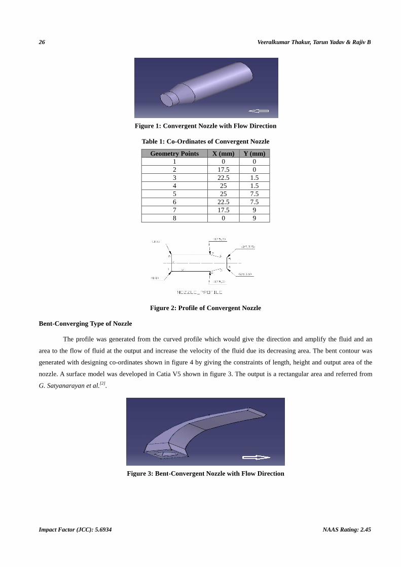
Bent-Converging Type of Nozzle
The profile was generated from the curved profile which would give the direction and amplify the fluid and an
area to the flow of fluid at the output and increase
generated with designing co-ordinates shown in fig
nozzle. A surface model was developed in Catia V5 shown in fi
G. Satyanarayan et al.[2] .
Figure 3: Bent
Veeralkumar Thakur, Tarun Yadav & Rajiv B
Impact Factor (JCC): 5.6934
Figure 1: Convergent Nozzle with Flow Direction
Table 1: Co-Ordinates of Convergent Nozzle
Geometry Points X (mm) Y (mm) 1 0 0 2 17.5 0 3 22.5 1.5 4 25 1.5 5 25 7.5 6 22.5 7.5 7 17.5 9 8 0 9
Figure 2: Profile of Convergent Nozzle
The profile was generated from the curved profile which would give the direction and amplify the fluid and an
area to the flow of fluid at the output and increase the velocity of the fluid due its decreasing area. The bent contour was
ordinates shown in figure 4 by giving the constraints of length, height and output area of the
eloped in Catia V5 shown in figure 3. The output is a rectangular area and referred from
Figure 3: Bent-Convergent Nozzle with Flow Direction
Veeralkumar Thakur, Tarun Yadav & Rajiv B
NAAS Rating: 2.45
The profile was generated from the curved profile which would give the direction and amplify the fluid and an
the velocity of the fluid due its decreasing area. The bent contour was
4 by giving the constraints of length, height and output area of the
3. The output is a rectangular area and referred from

CFD Assisted Nozzle Design in Burr Removal Process
www.tjprc.org
Figure 4: Profile of Bent
Convergent-Divergent Type of Nozzle (C
Converging-diverging nozzle is also known as
Gustaf de Lavel), as the name states, it has a smooth converging
as throat between converging and diverging section. This is the only nozzle that gets superso
converges and then diverges. But could be designed as per requirement.
M<1 or M=1 (i.e. choked) at the throat. Variation of Mach number i
D profile designed in figure 7, a surface model of the C
of profile is needed for impact on a large a
the nozzle is also suitable. At the output Mach number increases than one i.e. M>1, nozzle goes into supersonic zone.
Figure 5: Convergent
Figure 6: Variation of Mach number through C
Chocking Phenomenon in Nozzles
An effect of compressible flow in which the sonic velocity has been reached i.e. the subsonic velocity reaches
M=1 and in which the mass flow rate is maximum,
with a decrease in the pressure ratio (�air. When the (�∗/P) is further reduced the nozzle will
has reached its maximum possible value, the choked value. Thereafter mass flow rate remains constant.
Assisted Nozzle Design in Burr Removal Process
Figure 4: Profile of Bent-Convergent Nozzle
of Nozzle (C-D)
diverging nozzle is also known as De Lavel nozzle or ‘Condi’ nozzle (Developed by Swedish inventor
, as the name states, it has a smooth converging- diverging profile with a smooth small straight section call
nverging and diverging section. This is the only nozzle that gets superso
converges and then diverges. But could be designed as per requirement. The fluid may accelerate to its maximum speed at
roat. Variation of Mach number in this nozzle is shown in figure
7, a surface model of the C-D nozzle was generated in Catia V5 as shown in fig
of profile is needed for impact on a large area and output thrust of the fluid. For the purpose of chip blowing, this profile of
the nozzle is also suitable. At the output Mach number increases than one i.e. M>1, nozzle goes into supersonic zone.
Figure 5: Convergent-Divergent Nozzle with Flow Direction
Figure 6: Variation of Mach number through C-D nozzle
An effect of compressible flow in which the sonic velocity has been reached i.e. the subsonic velocity reaches
M=1 and in which the mass flow rate is maximum, is often said choking conditions in the nozzle. The flow rate increases
�∗/P) and attains the maximum value of the critical pressure ratio (
/P) is further reduced the nozzle will be in chocking conditions. The mass flow rate through the nozzle
has reached its maximum possible value, the choked value. Thereafter mass flow rate remains constant.
27
De Lavel nozzle or ‘Condi’ nozzle (Developed by Swedish inventor
diverging profile with a smooth small straight section call
nverging and diverging section. This is the only nozzle that gets supersonic at M>1. Usually it first
The fluid may accelerate to its maximum speed at
n this nozzle is shown in figure 5. Then based on the 2-
d in Catia V5 as shown in figure 6. This type
rea and output thrust of the fluid. For the purpose of chip blowing, this profile of
the nozzle is also suitable. At the output Mach number increases than one i.e. M>1, nozzle goes into supersonic zone.
Direction
An effect of compressible flow in which the sonic velocity has been reached i.e. the subsonic velocity reaches
is often said choking conditions in the nozzle. The flow rate increases
/P) and attains the maximum value of the critical pressure ratio (�∗/P) = 0.54 for
be in chocking conditions. The mass flow rate through the nozzle
has reached its maximum possible value, the choked value. Thereafter mass flow rate remains constant.
28
Impact Factor (JCC): 5.6934
�∗� = ��������
� ��������
��� ����
Put �∗�! = � �
�" � ���� �∗
�" = � #��
��
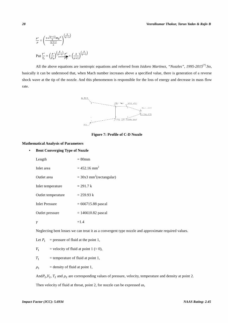
All the above equations are isentropic equations
basically it can be understood that, when Mach number increases above a specified value, there is generation of a reverse
shock wave at the tip of the nozzle. And this phenomenon is responsible for the loss of energy and decrease in mass flow
rate.
Mathematical Analysis of Parameters
• Bent Converging Type of Nozzle
Length = 80mm
Inlet area = 452.16 mm
Outlet area = 30x3 mm
Inlet temperature = 291.7 k
Outlet temperature = 259.93 k
Inlet Pressure = 666715.88 pascal
Outlet pressure = 146610.82 pascal
� =1.4
Neglecting bent losses we can treat it as a convergent type nozzle and approxima
Let �� = pressure of fluid at the point 1,
$� = velocity of fluid at point 1 (
%� = temperature of fluid at point 1,
�� = density of fluid at point 1,
And�#,$#, %# and �# are corresponding values of pressure, velocity, temperature and density at point 2.
Then velocity of fluid at throat, point 2, for nozzle can be expressed as,
Veeralkumar Thakur, Tarun Yadav & Rajiv B
Impact Factor (JCC): 5.6934
��
���
the above equations are isentropic equations and referred from Isidoro Martinez, “Nozzles”, 1995
basically it can be understood that, when Mach number increases above a specified value, there is generation of a reverse
the nozzle. And this phenomenon is responsible for the loss of energy and decrease in mass flow
Figure 7: Profile of C-D Nozzle
Mathematical Analysis of Parameters
Nozzle
= 80mm
= 452.16 mm2
= 30x3 mm2(rectangular)
= 291.7 k
= 259.93 k
= 666715.88 pascal
= 146610.82 pascal
=1.4
Neglecting bent losses we can treat it as a convergent type nozzle and approximate required values.
= pressure of fluid at the point 1,
= velocity of fluid at point 1 (≈ 0),
= temperature of fluid at point 1,
= density of fluid at point 1,
are corresponding values of pressure, velocity, temperature and density at point 2.
Then velocity of fluid at throat, point 2, for nozzle can be expressed as,
Veeralkumar Thakur, Tarun Yadav & Rajiv B
NAAS Rating: 2.45
Isidoro Martinez, “Nozzles”, 1995-2015[7].So,
basically it can be understood that, when Mach number increases above a specified value, there is generation of a reverse
the nozzle. And this phenomenon is responsible for the loss of energy and decrease in mass flow
te required values.
are corresponding values of pressure, velocity, temperature and density at point 2.

CFD Assisted Nozzle Design in Burr Removal Process 29
www.tjprc.org [email protected]
V# = #γ�γ(��
)�ρ� *1 − �)�)�
γ��γ -
Above equation is referred from Isidoro Martinez, “Nozzles”, 1995-2015[7].
P�= ρ�RT�
666715.88 = ρ� ∗ (432) ∗ (291.7)
ρ� = 5.290 kg/m>
V# = #∗�.?(�.?(�)
@@@A�B.CCB.#DE *1 − ��?@@�E.C#
@@@A�B.CC �.F��
�.F -
= G7 ∗ 126033.24 ∗ I0.35126J = 556.68 m/s
Similarly, the other nozzle calculations were done as shown below.
• Converging- Diverging Type of Nozzle
Length = 30mm
Inlet area =452.16 mm2
Outlet area = 30 x 3 mm2 (rectangular)
Inlet temperature =292.57 k
Outlet temperature =288.4489 k
Inlet Pressure =672950.69 pascal
Outlet pressure = 174899.88 pascal
P�= ρ�RT�
672950.69 = ρ� ∗ (432) ∗ (292.5)
ρ� = 5.365 kg/m>
V# = #∗�.?(�.?(�)
@A#DBE.@DB.>@B *1 − ��A?CDD.CC
@A#DBE.@D �.F��
�.F -
= G7 ∗ 125433.49 ∗ I0.3195J = 529.65 m/s
• Converging Type of Nozzle
Length = 41 mm
Inlet area = 254.34mm2
Outlet area = 113.04mm2
30 Veeralkumar Thakur, Tarun Yadav & Rajiv B
Impact Factor (JCC): 5.6934 NAAS Rating: 2.45
Inlet temperature =296.87 k
Outlet temperature =237.34 k
Inlet Pressure =708265.25 pascal
Outlet Pressure = 384317.90 pascal
From equation (1),
V# = #γ(γ(�)
)�ρ� *1 − �)�
)� γ��γ -
P�= ρ�RT�
708265.25 = ρ� ∗ (432) ∗ (296.87)
ρ� = 5.522 kg/m>
V# = #∗�.?(�.?(�)
AEC#@B.#BB.B## *1 − �>C?>�A.DE
AEC#@B.#B �.F��
�.F -
= G7 ∗ 128262.45 ∗ I0.1599J = 378.89 m/s
Computational Fluid Dynamic Analysis
Geometry
Table 2: Grid Details
Sr. No. Nozzle Geometry Grid Type Number of Elements
(Millions) Number of Nodes
(Millions) 1. Bent-convergent Fine 4.2 0.9 2. C-D Fine 2.5 0.6 3. Convergent Fine 1.5 0.4
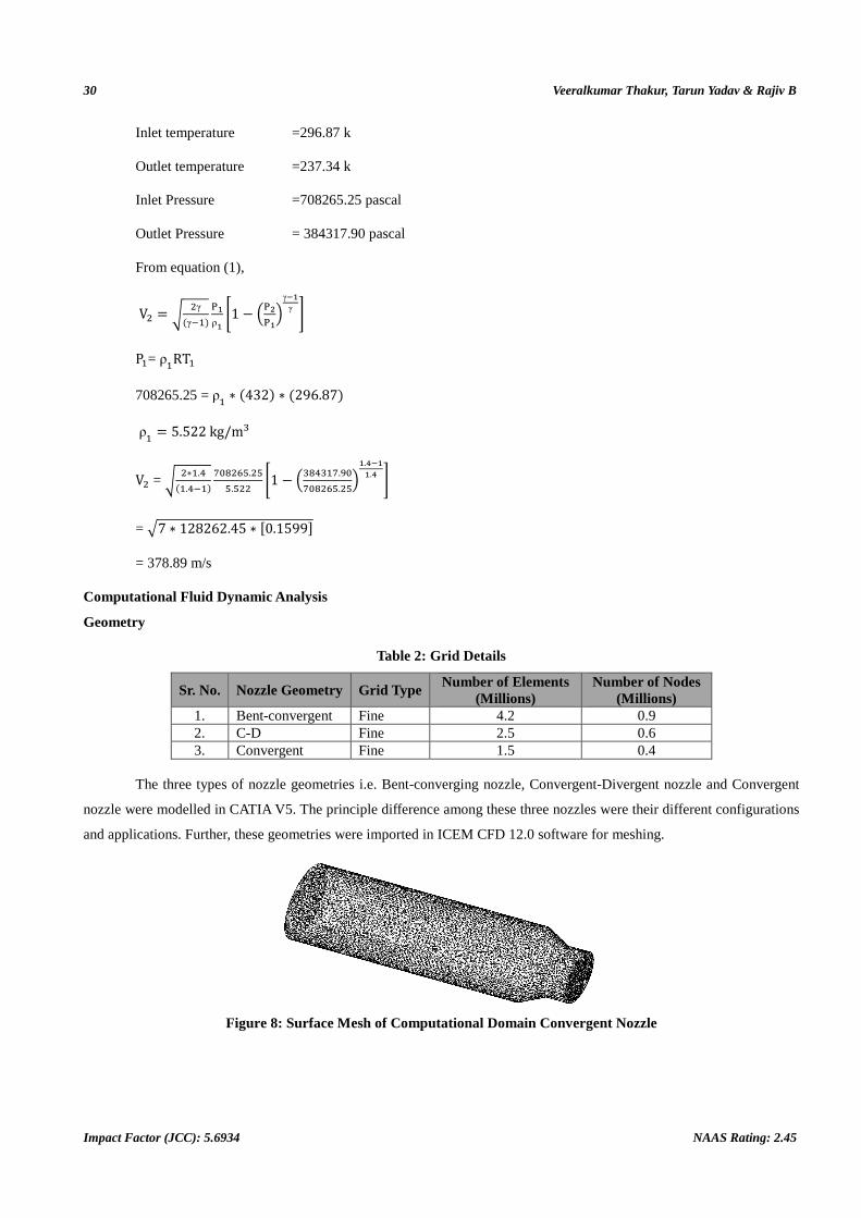
The three types of nozzle geometries i.e. Bent-converging nozzle, Convergent-Divergent nozzle and Convergent
nozzle were modelled in CATIA V5. The principle difference among these three nozzles were their different configurations
and applications. Further, these geometries were imported in ICEM CFD 12.0 software for meshing.
Figure 8: Surface Mesh of Computational Domain Convergent Nozzle

CFD Assisted Nozzle Design in Burr Removal Process 31
www.tjprc.org [email protected]
Mesh Generation
The fine surface and volume mesh for all three type of nozzles were generated in ICEM CFD 12.0 software. All
meshes are hybrid mesh made with the combination of triangular elements, tetra elements, and prism layers. Table.2 shows
the mesh details of various grids. Figure 8, 9, and 10 shows the wire frame of surface mesh of, Convergent nozzle, Bent-
converging and C-D nozzle respectively. The grids were sufficiently fine near the walls, away from the wall and
boundaries to capture the exact flow physics. The prism layers were generated near the walls so that the viscous behavior
and turbulence of internal fluid can be accurately predicted. Figure 11 represents the cut section of a volume mesh, where
prism layer are generated at the wall of a bent-convergent nozzle. Similar type of prism layers are also generated in
Convergent and C-D type nozzle. After meshing, CFD simulations in ANSYS FLUENT 12.0 were carried out on all grids
to analyze the flow behavior of various nozzles.
BOUNDARY CONDITIONS
The internal flow analysis was carried out by running simulations in commercial software ANSYS Fluent 12.0
version. The dimensional units in Fluent were set to SI.
Figure 9: Surface Mesh of Computational Domain and Bent-Convergent Nozzle
Material Properties
The test case is a compressible flow problem where the value of Mach number varies from inlet to exit. Ideal gas
was considered as the material. The various gas properties taken are as follows:
• Density = Ideal gas density
• Specific Heat capacity (Cp) = 1006.43 J/Kg.K
• Viscosity = 1.7894 e-5 Kg/m-s
• Thermal conductivity = 0.0242 W/m.K
• Molecular weight = 28.966 kg/kgmol.
Following are the boundary conditions which were set before running the simulation:
Figure 10: Surface Mesh of Computational Domain and C-D Nozzle

32 Veeralkumar Thakur, Tarun Yadav & Rajiv B
Impact Factor (JCC): 5.6934 NAAS Rating: 2.45
• Nozzle Inlet
Nozzle inlet was set as a pressure inlet, where gauge total pressure was taken as 6 bar. Inlet temperature was set to
297 K.
• Outlet of the Nozzle
Outlet pressure was set to atmospheric pressure i.e. 1 bar and outlet temperature was set to 0 K.
• Wall
The nozzle was considered as a stationary wall with no slip condition
• Control Setup and Discretization
The Density based solver with k-e turbulence model and energy equation on was considered for simulations. In
solution controls, the Turbulence Dissipation rate, Turbulence Kinetic Energy, and Turbulence Viscosity were set to 0.8, 0.8
and 1 respectively. The under relaxation factors were considered as default value. In solution methods, the implicit
formulation with flux type Roe-FDS was set. The least cell square gradient with second order upwind discretization,
turbulent kinetic energy and turbulence dissipation rate was considered.
• Initialization
The solution was initialized with hybrid initialization. The convergence criteria was set to 10-3.
COMPUTATIONAL FLUID DYNAMIC RESULTS
Residual Plot
Figure 12 shows the residual plot of convergent nozzle. It is noticed that residuals are dropped up to 10-3 in 2000
iterations and after that solution becomes stable. This signifies that solution is converged. The Bent nozzle and C-D nozzle
residuals are dropped up to 10-3 in 1800 iterations and after that solution become stable.
Figure 11: Prism Layer at Boundries
Figure 12: Residual plot of Convergent Nozzle

CFD Assisted Nozzle Design in Burr Removal Process 33
www.tjprc.org [email protected]
PRESSURE CONTOUR PLOT
Figure 13, 14 and 15 shows the contour pressure plot of Convergent nozzle, Bent Convergent and Convergent-
Divergent nozzle respectively. The pressure found decreased gradually from inlet to outlet throughout the length of the
nozzle. This confirms the physics requirement, as stated by Bernoulli’s that drop in pressure lead to increase in velocity
along the expansion zone. An uneven drop in pressure up to 50000 Pascal at exit is noticed in both Bent-converging and
Convergent-Divergent type nozzles. This has arisen due to formation of heavy shock waves, which in turn lead to choking
and reverse flow at exit. Hence efficiency of these nozzles got decreased. The pressure drop in convergent type nozzle was
found satisfactory as per isentropic relation.
Figure 13: Pressure Contour of Convergent Nozzle
Figure 14: Pressure Contour of Bent-Convergent Nozzle
Figure 15: Pressure Contour of C-D Nozzle
Mach Number Contour Plot
The Mach number contour plot of various nozzle are shown in figure 16, 17 and 18. It is visualized that Mach
number is gradually increasing from inlet to exit. The flow at exit is found supersonic (M>1) in Bent and Convergent-
Divergent type nozzles while in Convergent nozzle it was found subsonic (<1).

34 Veeralkumar Thakur, Tarun Yadav & Rajiv B
Impact Factor (JCC): 5.6934 NAAS Rating: 2.45
The Mach number near the wall is high due to turbulence and viscosity of the fluid. In C-D type nozzle, the Mach
number in convergent area and throat is found same.
Figure 16: Mach Number Contour of Convergent Nozzle
Figure 17: Mach Number Contour of Bent-Convergent Nozzle
Figure 18: Mach Number Contour of C-D Nozzle
Figure 19: Density Contour of Convergent Nozzle

CFD Assisted Nozzle Design in Burr Removal Process 35
www.tjprc.org [email protected]
Figure 20: Density Contour of Bent-Convergent Nozzle
Figure 21: Density Contour of C-D Nozzle
Density Contour Plot
The density contour plot of various nozzle are shown in figure 19, 20 and 21. The density dropped gradually from
inlet to exit throughout the nozzle length. It is visualized that density varies from 7.5 to 0.5 in C-D nozzle and bent nozzle
and 8 to 5.2 in convergent nozzle C-D nozzle Mach number is gradually increasing from inlet to exit. This proves the
Bernoulli’s theory as per equation where density and pressure are inversely proportional to velocity of fluid in
compressible flows.
Validation
The CFD results of Fluent for various nozzles were validated by comparing the values of exit velocity (V2)
obtained from CFD with the value obtained from mathematical formulae. The exit velocity values of nozzles were found
almost same with the CFD exit velocity values. Further, the convergent type nozzle was manufactured and results were
found in good agreement with the CFD results.
ACKNOWLEDGEMENTS
Authors are greatly thankful to Hindustan Aeronautics Limited, Nasik division and Production Engineering
Department of College of Engineering, Pune-411005 which were of support during their research.
RESULTS AND CONCLUSIONS
The aim of this paper was to develop an efficient air amplification device i.e. a nozzle, fit for aluminum chip
blowing purposes in 5 axis CNC machine with the help of CFD analysis. Following are the conclusions:
• The mass flow rate at inlet and exit were found different for Bent-Convergent and Convergent-Divergent nozzle.
Hence, it can be concluded that Chocking has occurred due to varying cross-section and it would cause reverse
flow at exit which in turn would drop velocity drastically. However, the mass flow rate at inlet and exit were

36 Veeralkumar Thakur, Tarun Yadav & Rajiv B
Impact Factor (JCC): 5.6934 NAAS Rating: 2.45
found same for Convergent nozzle.
• From the results, it is found that Bent-Convergent nozzle gives exit velocity of 556.68 m/s, Converging-Diverging
nozzle gives 529.65 m/s and Converging nozzle gives 378.89 m/s.
• So, compared with the Bent-Convergent nozzle and Convergent-Divergent nozzle, the velocity of Convergent
nozzle was 31.93% and 28.46% less respectively. But due to chocking in Bent-Convergent and Convergent-
Divergent type nozzle, we opted Convergent nozzle for blow off purpose.
• Velocity of nozzle increases at the cost of pressure drop. From analysis it can be seen that Bent-Converging nozzle
gives pressure drop of 78.01%, the Convergent-Divergent nozzle gives drop of 74.01% and Convergent nozzle
gives 45.73% drop. So, more pressure losses in C-D and Bent-Convergent nozzles.
• The output Mach number of Bent-Convergent nozzle was found out to be 1.423, Convergent-Divergent nozzle
was 1.56 and Convergent nozzle was 0.957.
• The temperature drop in bent-convergent nozzle was 10.91%, in convergent-divergent nozzle was 1.41% and in
convergent nozzle was 20.05%.
• From above results and analysis, the best nozzle suitable for chip blowing operation in CNC machine is
Convergent nozzle.
REFERENCES
1. Eric Gamble, Dwain Terrell and Rich DeFrancesco, “Nozzle Selection and Design Criteria”, theAmerican Institute of
Aeronautics and Astronautics, 40th AIAA/ASME/SAE/ASEE Joint Propulsion Conference and Exhibit 11-14 July 2004.
2. G. Satyanarayan, Ch. Varun and S.S. Naidu, “CFD Analysis of Convergent-Divergent Nozzle”, ACTA Technica Corviniensis-
Bulletin of Engineering Tome VI (year 2013)- Fascicule 3[July-September] 2013, ISSN 2067-3809.
3. Pourmahmoud, N., et. al “Computational Fluid Dynamics Analysis of Helical Nozzles Effects”, Thermal Science, Year 2012,
Vol. 16, pp. 151-166.
4. Mohan Kumar G, Dominic Xavier Fernando, R. Muthu Kumar, “Design and Optomization of De Lavael Nozzle to Prevent
Shock Induced Flow Separation”, Advances in Aerospace science and Applications, Volume 3, Number 2 (2013), pp. 119-124.
5. R. K Rajput, “Engineering Thermodynamics”.
6. Pardhasaradhi Natta, V.Ranjith Kumar, Dr. Y.V.Hanumantha Rao, “Flow Analysis of Rocket Nozzle Using Computational
Fluid Dynamics (Cfd)”, International Journal of Engineering Research and Applications(IJERA), Vol. 2, Issue 5, September-
October 2012,pp. 1226-1235.
7. Isidoro Martinez, “Nozzles”, 1995-2015.
8. B.Krishna Prafulla, Dr. V. Chitti Babu, P.Govinda Rao, “Cfd Analysis of Convergent-Divergent Supersonic nozzle”,
International Journal of computational Enggineering Research, Vol. 3, Issue 5, May-2013.
9. Gutti Rajeswara Rao, U.S. Ramakanth, A. Lakshman, “Flow Analysis in aConvergent-Divergent Nozzle using CFD”,
International Journal Of Research in Mechanical Enggineering, Vol. 1, Issue 2, Oct-Dec 2013, pp. 136-144.
10. MD. Safayet Hossain, Muhammad Ferdous Raiyan, Nahed Hassan Jony, “Comparative Study of Supersonics Nozzles”,
International Journal of Research in Engineering and Technology, Vol. 3, Issue: 10, Oct-2014, ISSN: 2321-7308.