5. IJMPERD - FE THERMAL ANALYSIS AND EXPERIMENTAL VALIDATION.pdf
8
www.tjprc.org [email protected] FE THERMAL ANALYSIS AND EXPERIMENTAL VALIDATION ON THE COMPONENTS OF SI ENGINES K. KISHOR Assistant Professor, Mechanical Engineering Department, Chaitanya Bharathi Institute of Technology, Hyderabad, Telangana, India ABSTRACT To test the performance of different versions of SI engines (conventional engine, CE and catalytic coated engine, CCE, copper being coated on the piston crown and on the inner surface of cylinder head) with any new fuel or fuel blend, the possibility of deterioration of lubricating oil placed in between piston and liner of the engine is to be checked, which results in damaging the mechanical stability and decrease in the engine efficiency. As it i s difficult to check practically, FE thermal analysis was adopted. FEA is important in evaluating the lubricating oil deterioration, as the liner is subjected to high temperatures and the pi ston crown and inside of the cylinder head are coa ted with copper. Thermal analysis includes the determination of temperature distribution and heat flow rate across the components (piston, liner and cylinder head) of SI engine. The prediction is important which determines the efficient combustion by means o f cata lytic coa ting on the surface of piston crown and over the inside surface of cylinder hea d. These studies are conducted on CE and also on CCE in order to emphasize the advantage of CCE o ver CE in producing efficient combustion. The temp erature and heat flux rate at the component surfaces was found to be increasing along both axis and radius o f piston, liner and cylinder head of CCE over CE. The temperature of lub ricating oil was also found to be increasing with CCE over CE but it was found to be within the safe temperature limits to avoid deterioration. KEYWORDS: Conventional Engine, Copper Coated Engine, FE Thermal Analysis, Lubricating Oil, Deterioration Received: Jan 11, 2016; Accepted: Jan 17, 2016; Published: Jan 22, 2016; Paper Id.: IJMPERDFEB20165 INTRODUCTION Many researchers adopted different theoretical techniques for predicting the temperatures and heat flux rate either in the conventional piston [1], [2], [3] or on the cylinder head [4], [5] or both on piston and cylinder head [6]. However, these researchers concentrated their efforts on the thermal analysis of conventional engine only, but not on copper coated engine components. The CCE consists of copper coated piston, liner and copper coated cylinder head. The piston ring grooves, the varying properties of copper coated crown, liner and copper coated cylinder head with differing boundary conditions call for accurate analysis for predicting temperature distribution and heat flux rate in the piston, liner and cylinder head. Very little literature is available for thermal analysis of different SI engine version [7] and CI engine version [8], [9]. With advanced computer code like ANSYS, an attempt was made to predict the temperature distribution and heat flow rate using FEA. The prediction of temperatures and heat flow in these components is important which determines the efficient combustion by means of copper coating on the top surface of piston crown and over the inside surface of cylinder head. The values of temperature and heat flux along the axis and radius of each component predicted by FEA were validated with the values obtained by experimentation. O r i g i n a l A r t i c l e International Journal of Mechanical and Production Engineering Research and Development (IJMPERD) ISSN(P): 2249-6890; ISSN(E): 2249-8001 Vol. 6, Issue 1, Feb 2016, 41-48 © TJPRC Pvt. Ltd.
-
Upload
anonymous-svjv413 -
Category
Documents
-
view
232 -
download
0
Transcript of 5. IJMPERD - FE THERMAL ANALYSIS AND EXPERIMENTAL VALIDATION.pdf

7/26/2019 5. IJMPERD - FE THERMAL ANALYSIS AND EXPERIMENTAL VALIDATION.pdf
http://slidepdf.com/reader/full/5-ijmperd-fe-thermal-analysis-and-experimental-validationpdf 1/8
www.tjprc.org [email protected]
FE THERMAL ANALYSIS AND EXPERIMENTAL VALIDATION ON
THE COMPONENTS OF SI ENGINES
K. KISHOR
Assistant Professor, Mechanical Engineering Department, Chaitanya Bharathi
Institute of Technology, Hyderabad, Telangana, India
ABSTRACT
To test the performance of different versions of SI engines (conventional engine, CE and catalytic coated
engine, CCE, copper being coated on the piston crown and on the inner surface of cylinder head) with any new fuel or
fuel blend, the possibility of deterioration of lubricating oil placed in between piston and liner of the engine is to be
checked, which results in damaging the mechanical stability and decrease in the engine efficiency. As it is difficult to
check practically, FE thermal analysis was adopted. FEA is important in evaluating the lubricating oil deterioration, as
the liner is subjected to high temperatures and the piston crown and inside of the cylinder head are coated with copper.
Thermal analysis includes the determination of temperature distribution and heat flow rate across the components
(piston, liner and cylinder head) of SI engine. The prediction is important which determines the efficient combustion by
means of catalytic coating on the surface of piston crown and over the inside surface of cylinder head. These studies
are conducted on CE and also on CCE in order to emphasize the advantage of CCE over CE in producing efficient
combustion. The temperature and heat flux rate at the component surfaces was found to be increasing along both axis
and radius of piston, liner and cylinder head of CCE over CE. The temperature of lubricating oil was also found to be
increasing with CCE over CE but it was found to be within the safe temperature limits to avoid deterioration.
KEYWORDS: Conventional Engine, Copper Coated Engine, FE Thermal Analysis, Lubricating Oil, Deterioration
Received: Jan 11, 2016; Accepted: Jan 17, 2016; Published: Jan 22, 2016; Paper Id.: IJMPERDFEB20165
INTRODUCTION
Many researchers adopted different theoretical techniques for predicting the temperatures and heat flux
rate either in the conventional piston [1], [2], [3] or on the cylinder head [4], [5] or both on piston and cylinder
head [6]. However, these researchers concentrated their efforts on the thermal analysis of conventional engine
only, but not on copper coated engine components. The CCE consists of copper coated piston, liner and coppercoated cylinder head. The piston ring grooves, the varying properties of copper coated crown, liner and copper
coated cylinder head with differing boundary conditions call for accurate analysis for predicting temperature
distribution and heat flux rate in the piston, liner and cylinder head. Very little literature is available for thermal
analysis of different SI engine version [7] and CI engine version [8], [9]. With advanced computer code like
ANSYS, an attempt was made to predict the temperature distribution and heat flow rate using FEA. The prediction
of temperatures and heat flow in these components is important which determines the efficient combustion by
means of copper coating on the top surface of piston crown and over the inside surface of cylinder head. The
values of temperature and heat flux along the axis and radius of each component predicted by FEA were validated
with the values obtained by experimentation.
Or i gi n al Ar t i c l e
International Journal of Mechanical and Production
Engineering Research and Development (IJMPERD)
ISSN(P): 2249-6890; ISSN(E): 2249-8001
Vol. 6, Issue 1, Feb 2016, 41-48
© TJPRC Pvt. Ltd.

7/26/2019 5. IJMPERD - FE THERMAL ANALYSIS AND EXPERIMENTAL VALIDATION.pdf
http://slidepdf.com/reader/full/5-ijmperd-fe-thermal-analysis-and-experimental-validationpdf 2/8
42 K. Kishor
Impact Factor(JCC): 5.6934 NAAS Rating: 2.45
METHODOLOGY
In the catalytic coated engine, a high thermal conductive catalytic material like copper was coated on the cylinder
head inside surface and top surface of piston crown by METCO flame spray gun. Initially for a thickness of 100 microns
thickness, a bond coating of nickel-cobalt-chromium was sprayed. On this coating, an alloy of copper (89.5%), aluminium
(9.5%) and iron (1%) was coated for another 300 microns thickness. The bond strength of the coating was so high that it
does not wear off even after operating it for 50 hrs continuously [10], [11].
Plate 1 shows the photographic view of copper coated piston, liner and copper coated cylinder head.
Plate 1: Photographic view of Copper Coated Piston,
Liner and Copper Coated Cylinder Head
Thermal analysis is done in two broad stages as, i) Geometric modeling, and, ii) Finite element modeling.
In geometric modeling, the outer boundary of one half of the piston, liner and cylinder head are created and
necessary patching is generated. Solid quadrant 4-node 55 (axi-symmetric) 2-dimensional (acts as plane 55) elements are
chosen [12].
Figure 1 shows the geometry created for the thermal analysis for CCE.
Figure 1: Geometric Model Created for the Thermal Analysis for CCE
In the FEM, each patch is further divided into smaller elements in critical areas like crown and cylinder head,
where temperature gradients are high while coarser grid is adopted in the piston and liner regions where variation of
temperature is not much. Mesh is refined based on convergence requirements and the final mesh is shown in Figure 2, for
CCE.
Figure 2: Mesh Employed in the Thermal Analysis for CCE

7/26/2019 5. IJMPERD - FE THERMAL ANALYSIS AND EXPERIMENTAL VALIDATION.pdf
http://slidepdf.com/reader/full/5-ijmperd-fe-thermal-analysis-and-experimental-validationpdf 3/8
FE Thermal Analysis and Experimental Validation on the Components of SI Engines 43
www.tjprc.org [email protected]
The methodology was obtained from [1], [4, [5] for determining temperature distribution for piston, liner and
cylinder head respectively for SI engine. However, the actual boundary conditions for the present problem were obtained
with the values of experimentation [8] and were given below:
Top surface of piston, 235 W/ m2 K, = 920 0C
Bottom side of the piston, 450 W/ m2 K, = 100 0C
Air jacket side of liner, 200 W/ m2 K, = 60 0C
Fins, 120 W/ m2 K, = 30
0C
Figure 3 shows the schematic diagram of the experimental set up for measuring the surface temperature of liner
and cylinder head, while, Plate 3 shows the photographic view of the, while same.
Figure 3: Schematic Diagram of the Experimental Set Up for Measuring the
Surface Temperature of Liner and Cylinder Head
Plate 2: Photographic View of the Experimental Set Up for Measuring the
Surface Temperature of Liner and Cylinder Head
Four holes of suitable diameter are drilled on the top portion of the liner and cylinder head and the thermocouples
are inserted through these holes and are spot welded. These thermocouples are connected to the temperature sensor.
RESULTS AND DISCUSSIONS
Figure 4 shows the distribution of isotherms from finite element analysis in CE, while Figure 5 represents the
distribution of isotherms in CCE from finite element analysis.

7/26/2019 5. IJMPERD - FE THERMAL ANALYSIS AND EXPERIMENTAL VALIDATION.pdf
http://slidepdf.com/reader/full/5-ijmperd-fe-thermal-analysis-and-experimental-validationpdf 4/8
44 K. Kishor
Impact Factor(JCC): 5.6934 NAAS Rating: 2.45
Figure 4: Isotherms of Thermal Analysis for CE
Figure 5: Isotherms of Thermal Analysis for CCE
Figure 6 shows different heat flux regions in the piston, liner and cylinder head of CE, while Figure 7 shows
different heat flux regions in the piston, liner and cylinder head of CCE.
Figure 6: Heat Flow in the Thermal Analysis for CE
Figure 7: Heat Flow in the Thermal Analysis for CCE
The predicted values of temperatures and the % increase in the heat flow rate at various locations of the piston,
lubricating oil, liner and cylinder head for CE and CCE were presented in the Table 1.

7/26/2019 5. IJMPERD - FE THERMAL ANALYSIS AND EXPERIMENTAL VALIDATION.pdf
http://slidepdf.com/reader/full/5-ijmperd-fe-thermal-analysis-and-experimental-validationpdf 5/8
FE Thermal Analysis and Experimental Validation on the Components of SI Engines 45
www.tjprc.org [email protected]
Table 1: Predicted Values of Temperatures and the % Increase in the Heat Flow Rate
Component Location
Temperatures
Predicted by FEA
% Deviation in the Heat
Flux (Predicted by FEA)
along the Component of
CCE over CE
CE CCE
Piston
Top surface
(Crown)183 236 +20.2%
Bottom surface 105 206 +10.1%
Outer periphery 164 217 +18.2%
Liner
Inner wall 228 244 +15.4%
Outer radius 123 141 +11.9%
Bottom surface 61 82 +7.8%
Cylinder
Head
Bottom
(Inner surface)634 703 +20.2%
Top surface 429 506 +14.6%
Outer radius 311 395 +18.1%
From the Table 1 it was observed that, the surface temperature of each component of CCE is greater than that of
CE. This was due to copper coating done on the piston crown and on the inner surface of cylinder head. The temperature
decreases at the outer periphery of each component, as it is subjected to the combined cooling effect of the lubricating oil
and fins. The maximum % increase in the heat flux is more in CCE over CE along the axis and along the radius of each
component. Since the piston crown and inner surface of cylinder head were copper coated, it absorbs more amount of heat
from the surroundings with which temperature increases and hence heat flux also increases. As the depth of piston and
liner and height of cylinder head increases, heat flux decreases. This was due to the thermal resistance offered by the
component material against heat flow. As the radius of piston, liner and cylinder head increases, the percentage (%)
increase in the heat flux decreases as their outer periphery was subjected to cooling by means of either lubricating oil or
fins or with both.
As the piston is a moving boundary surface, it is very difficult to measure the temperature practically at the crown
of the piston. Also, as the gap between the piston and liner is only 0.5 mm, it is highly difficult to insert a thermocouple for
measuring the temperature of lubricating oil. Hence, an attempt is made to measure the temperature for the cylinder head
and liner only by means of thermocouple method. The results obtained by FEA are correlated with the experimental means.
If this correlation is found to be within the range, it will be very easy to predict the lubricating oil temperature also, by
which the performance of the lubricating oil can be assessed for CE and CCE, especially for CCE. From the Figure 4 it was
observed that, the lubricating oil temperature varied between 106 0C to 1500C for CE, while it varied between 1270C to
1720C for CCE as seen from Figure 5. This shows that, the lubricating oil temperatures are within the limits, as the safe
temperature limit [7], [13] (to avoid deterioration) of lubricating oil was 1800C. Hence, it was mentioned that, catalytic
coated engine will not result in the deterioration of lubricating oil.
The temperatures at the inner side of the liner and cylinder head predicted by FEA were compared with the results
obtained by experimentation, in order to ascertain the deviation of FEA results from experimental results
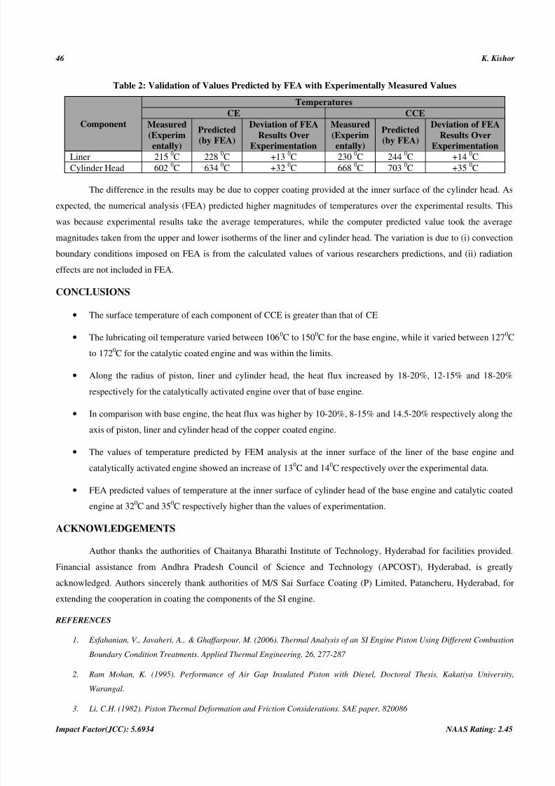
Table 2 shows the comparison on the variation of temperatures in the liner and cylinder head obtained
theoretically and experimentally for the base engine and catalytically activated engine.
7/26/2019 5. IJMPERD - FE THERMAL ANALYSIS AND EXPERIMENTAL VALIDATION.pdf
http://slidepdf.com/reader/full/5-ijmperd-fe-thermal-analysis-and-experimental-validationpdf 6/8
46 K. Kishor
Impact Factor(JCC): 5.6934 NAAS Rating: 2.45
Table 2: Validation of Values Predicted by FEA with Experimentally Measured Values
Component
Temperatures
CE CCE
Measured
(Experimentally)
Predicted
(by FEA)
Deviation of FEA
Results OverExperimentation
Measured
(Experimentally)
Predicted
(by FEA)
Deviation of FEA
Results OverExperimentation
Liner 2150C 228
0C +13
0C 230
0C 244
0C +14
0C
Cylinder Head 6020C 634
0C +32
0C 668
0C 703
0C +35
0C
The difference in the results may be due to copper coating provided at the inner surface of the cylinder head. As
expected, the numerical analysis (FEA) predicted higher magnitudes of temperatures over the experimental results. This
was because experimental results take the average temperatures, while the computer predicted value took the average
magnitudes taken from the upper and lower isotherms of the liner and cylinder head. The variation is due to (i) convection
boundary conditions imposed on FEA is from the calculated values of various researchers predictions, and (ii) radiation
effects are not included in FEA.
CONCLUSIONS
• The surface temperature of each component of CCE is greater than that of CE
• The lubricating oil temperature varied between 1060C to 1500C for the base engine, while it varied between 1270C
to 1720C for the catalytic coated engine and was within the limits.
• Along the radius of piston, liner and cylinder head, the heat flux increased by 18-20%, 12-15% and 18-20%
respectively for the catalytically activated engine over that of base engine.
•
In comparison with base engine, the heat flux was higher by 10-20%, 8-15% and 14.5-20% respectively along the
axis of piston, liner and cylinder head of the copper coated engine.
• The values of temperature predicted by FEM analysis at the inner surface of the liner of the base engine and
catalytically activated engine showed an increase of 130C and 14
0C respectively over the experimental data.
• FEA predicted values of temperature at the inner surface of cylinder head of the base engine and catalytic coated
engine at 320C and 35
0C respectively higher than the values of experimentation.
ACKNOWLEDGEMENTS
Author thanks the authorities of Chaitanya Bharathi Institute of Technology, Hyderabad for facilities provided.
Financial assistance from Andhra Pradesh Council of Science and Technology (APCOST), Hyderabad, is greatly
acknowledged. Authors sincerely thank authorities of M/S Sai Surface Coating (P) Limited, Patancheru, Hyderabad, for
extending the cooperation in coating the components of the SI engine.
REFERENCES
1. Esfahanian, V., Javaheri, A., & Ghaffarpour, M. (2006). Thermal Analysis of an SI Engine Piston Using Different Combustion
Boundary Condition Treatments. Applied Thermal Engineering, 26, 277-287
2. Ram Mohan, K. (1995). Performance of Air Gap Insulated Piston with Diesel, Doctoral Thesis. Kakatiya University,
Warangal.
3. Li, C.H. (1982). Piston Thermal Deformation and Friction Considerations. SAE paper, 820086
7/26/2019 5. IJMPERD - FE THERMAL ANALYSIS AND EXPERIMENTAL VALIDATION.pdf
http://slidepdf.com/reader/full/5-ijmperd-fe-thermal-analysis-and-experimental-validationpdf 7/8
FE Thermal Analysis and Experimental Validation on the Components of SI Engines 47
www.tjprc.org [email protected]
4.
Elisa Carvajal Trujillo., Francisco Jiménez-Espadafor J., José Becerra Villanueva, A., & Miguel Torres García. (2011).
Methodology for the Estimation of Cylinder Inner Surface Temperature in an Air-Cooled Engine. Applied Thermal
Engineering, 31, 1474 – 1481
5.
Elisa Carvajal Trujillo., Francisco Jiménez-Espadafor J., José Becerra Villanueva, A., & Miguel Torres García. (2012). Methodology for the Estimation of Head Inner Surface Temperature in an Air-Cooled Engine, Applied Thermal Engineering.
35, 202-211
6.
Mahdi Hamzehei., & Manochehr Rashidi. (2006). Determination of Piston and Cylinder Head Temperature Distribution in a
4-Cylinder Gasoline Engine at Actual Process. In Proceedings of the 4th WSEAS International Conference on Heat Transfer,
Thermal Engineering and Environment, 153-158
7. Ali Jafari., & Siamak Kazemzadeh Hannani. (2006). Effect of Fuel and Engine Operational Characteristics on the Heat Loss
from Combustion Chamber Surfaces of SI Engines. International Communications in Heat and Mass Transfer, 33, 122-134
8. Murali Krishna, M.V.S. (2004). Performance Evaluation of Low Heat Rejection (LHR) Diesel Engine with Alternative Fuels.
Doctoral Thesis. Jawaharlal Nehru Technological University, Hyderabad
9. Krishna Murthy, P.V. (2004). Studies on Bio-Diesel Using With LHR Diesel Engine. Doctoral Thesis. Jawaharlal Nehru
Technological University, Hyderabad
10.
Dhandapani, S. (1991). Theoretical and Experimental Investigation of Catalytically Activated Lean Burn Combustion.
Doctoral Thesis. Indian Institute of Technology, Madras
11.
Nedunchezhian, N. & Dhandapani, S. (2000). Experimental Investigation of Cyclic Variation of Combustion Parameters in a
Catalytically Activated Two Stroke SI Engine Combustion Chamber. Engineering Today, 2, 11-18
12.
Georges Cailletaud. (from website). Finite Lement: Matrix Formulation, Ecole des Mines de Paris, Centre des Mat’eriaux,
UMR CNRS 7633
13.
Heywood, J.B. (1988). Internal Combustion Engine Fundamentals, Thermo-Chemistry of Fuel Air Mixtures, Properties of
Working Fluids, McGraw-Hill Book Company, New York

7/26/2019 5. IJMPERD - FE THERMAL ANALYSIS AND EXPERIMENTAL VALIDATION.pdf
http://slidepdf.com/reader/full/5-ijmperd-fe-thermal-analysis-and-experimental-validationpdf 8/8