3. Design of Structures, Components, AP1000 European ... · Design of Structures, Components,...
55
3. Design of Structures, Components, AP1000 European Equipment and Systems Design Control Document EPS-GW-GL-700 3.6-1 Revision 1 3.6 Protection Against the Dynamic Effects Associated with the Postulated Rupture of Piping The effects of a postulated pipe rupture in the AP1000 are of several types. This section considers the effects that are localized to the area of the break and are a result of the dynamic effects of the pipe rupture including jet impingement, pipe whip, subcompartment pressurization, and fluid system decompression. This section describes the evaluation of the potential for and effects of these dynamic effects. It describes measures taken to protect systems and equipment from dynamic effects of pipe rupture when necessary. This section also considers the effects of spray wetting and flooding from pipe ruptures and cracks. Chapters 6 and 15 discuss the response of the system to changes in flow and pressure and loss of coolant and the response of the containment to the pressure and temperature changes. Pressure due to a break in a high energy line in the auxiliary building is vented into an adjacent building or to the atmosphere. The design transients listed in subsection 3.9.1 are used in evaluating the components of the reactor coolant system for effects due to internal pressure and temperature changes from postulated accidents. Section 3.11 discusses the qualification of the equipment required to function in the adverse environmental conditions including temperature, humidity, pressure, and chemical consequences. Pipe failure protection is provided according to the requirements of 10 CFR 50, Appendix A, General Design Criterion 4. In the event of a high- or moderate-energy pipe failure within the plant, adequate protection is provided so that essential structures, systems, or components are not impacted by the adverse effects of postulated piping failure. Essential systems and components are those required to shut down the reactor and mitigate the consequences of the postulated piping failure. Nonsafety-related systems are not required to be protected from the dynamic and environmental effects associated with the postulated rupture of piping except as described in subsection 3.6.1.1, item Q. The criteria used to evaluate pipe failure protection are generally consistent with NRC guidelines including those in the Standard Review Plan Sections 3.6.1 and 3.6.2, NUREG-1061, Volume 3 (Reference 11) and applicable Branch Technical Positions. Subsection 3.6.1 provides the design bases and criteria for the analysis required to demonstrate that essential systems are protected. The high- and moderate-energy systems representing the potential source of dynamic effects are listed. Additionally, the criteria for separation and the effects of adverse consequences are defined. Subsection 3.6.2 defines the criteria for postulated break location and configuration. High-energy pipes are evaluated for the effects of circumferential and longitudinal pipe breaks and through-wall cracks. Moderate-energy pipes are evaluated for the effects of through-wall cracks. Analysis methods and criteria for evaluating pipe whip and evaluating the consequences of jet impingement, motions of the pipe, and system depressurization on integrity and operability are provided. The evaluation of containment penetrations, pipe whip restraints, guard pipes, and other protective devices is also described. The criteria for excluding breaks in high-energy piping adjacent to containment penetrations are also provided. Evaluation of the dynamic effects of postulated breaks in the reactor coolant loop, main steam lines inside containment, and other primary piping inside containment equal to or greater than the
Transcript of 3. Design of Structures, Components, AP1000 European ... · Design of Structures, Components,...
3. Design of Structures, Components, AP1000 European Equipment and Systems Design Control Document
EPS-GW-GL-700 3.6-1 Revision 1
3.6 Protection Against the Dynamic Effects Associated with the Postulated Rupture of Piping
The effects of a postulated pipe rupture in the AP1000 are of several types. This section considers the effects that are localized to the area of the break and are a result of the dynamic effects of the pipe rupture including jet impingement, pipe whip, subcompartment pressurization, and fluid system decompression. This section describes the evaluation of the potential for and effects of these dynamic effects. It describes measures taken to protect systems and equipment from dynamic effects of pipe rupture when necessary. This section also considers the effects of spray wetting and flooding from pipe ruptures and cracks.
Chapters 6 and 15 discuss the response of the system to changes in flow and pressure and loss of coolant and the response of the containment to the pressure and temperature changes. Pressure due to a break in a high energy line in the auxiliary building is vented into an adjacent building or to the atmosphere. The design transients listed in subsection 3.9.1 are used in evaluating the components of the reactor coolant system for effects due to internal pressure and temperature changes from postulated accidents. Section 3.11 discusses the qualification of the equipment required to function in the adverse environmental conditions including temperature, humidity, pressure, and chemical consequences.
Pipe failure protection is provided according to the requirements of 10 CFR 50, Appendix A, General Design Criterion 4. In the event of a high- or moderate-energy pipe failure within the plant, adequate protection is provided so that essential structures, systems, or components are not impacted by the adverse effects of postulated piping failure. Essential systems and components are those required to shut down the reactor and mitigate the consequences of the postulated piping failure. Nonsafety-related systems are not required to be protected from the dynamic and environmental effects associated with the postulated rupture of piping except as described in subsection 3.6.1.1, item Q.
The criteria used to evaluate pipe failure protection are generally consistent with NRC guidelines including those in the Standard Review Plan Sections 3.6.1 and 3.6.2, NUREG-1061, Volume 3 (Reference 11) and applicable Branch Technical Positions.
Subsection 3.6.1 provides the design bases and criteria for the analysis required to demonstrate that essential systems are protected. The high- and moderate-energy systems representing the potential source of dynamic effects are listed. Additionally, the criteria for separation and the effects of adverse consequences are defined.
Subsection 3.6.2 defines the criteria for postulated break location and configuration. High-energy pipes are evaluated for the effects of circumferential and longitudinal pipe breaks and through-wall cracks. Moderate-energy pipes are evaluated for the effects of through-wall cracks. Analysis methods and criteria for evaluating pipe whip and evaluating the consequences of jet impingement, motions of the pipe, and system depressurization on integrity and operability are provided. The evaluation of containment penetrations, pipe whip restraints, guard pipes, and other protective devices is also described. The criteria for excluding breaks in high-energy piping adjacent to containment penetrations are also provided.
Evaluation of the dynamic effects of postulated breaks in the reactor coolant loop, main steam lines inside containment, and other primary piping inside containment equal to or greater than the
3. Design of Structures, Components, AP1000 European Equipment and Systems Design Control Document
EPS-GW-GL-700 3.6-2 Revision 1
6-inch nominal (ND 150 mm) pipe size (NPS) is eliminated for AP1000 based on mechanistic pipe break (leak-before-break) considerations. Those sections of high-energy piping that qualify for mechanistic pipe break are evaluated for only the effects of leakage cracks.
Subsection 3.6.3 describes the application of leak-before-break criteria to permit the elimination of pipe rupture dynamic effects considerations. Design guidelines aid in the design of piping systems that satisfy the requirements for mechanistic pipe break. Dynamic effects of postulated breaks are evaluated for those analyzable sections of high-energy piping systems that do not use the mechanistic pipe break methods.
The safety analyses in Chapter 15 and the requirements for emergency core cooling discussed in Section 6.3 and the environmental qualification of equipment discussed in Section 3.11 of this report are not changed by the use of mechanistic pipe break considerations for pipe rupture dynamic effects evaluations. Chapter 6 describes the containment subcompartment pressurization analyses including mechanistic pipe break considerations.
3.6.1 Postulated Piping Failures in Fluid Systems Inside and Outside Containment
A number of systems and components are necessary to shut the plant down in the event of a pipe rupture. These systems, termed essential systems, are protected from the postulated pipe ruptures. The essential systems for various pipe ruptures are the reactor coolant system, the steam generator system, the passive core cooling system, and the passive containment cooling system. In addition to these fluid systems, the protection and safety monitoring system and the Class 1E dc and UPS system are essential. The main control room and main control room habitability system are also protected as essential systems. In addition, containment penetrations and isolation valves (including those for nonessential systems) are essential.
Most of the equipment required for plant safety or safety-related shutdown is located inside containment. The piping inside containment also represents the most significant piping relative to plant safety and, therefore, is subject to the most stringent design and analysis requirements.
Essential equipment in the vicinity of piping that does not satisfy leak-before-break criteria is protected as required by the use of protective structures, pipe restraints, and separation. The need for protection of essential structures, systems and components is determined by evaluation of the dynamic effects. The design bases and criteria for the evaluation follow.
Evaluations are made based upon circumferential or longitudinal pipe breaks, through-wall cracks, or leakage cracks as determined by the appropriate criteria. At locations determined to be subject to a circumferential or longitudinal pipe break, dynamic effects such as jet impingement and pipe whip are evaluated.
At locations subject to through-wall cracks or leakage cracks, only effects such as spray wetting and flooding are evaluated. Through-wall cracks, which are postulated in high-energy piping and in moderate-energy lines, are larger and have a larger flow rate of water or steam than the leakage cracks postulated for high-energy piping, which satisfies the leak-before-break requirements.
The pressurization loads on structures and components are evaluated for postulated circumferential breaks and longitudinal breaks in piping that does not meet leak-before-break
3. Design of Structures, Components, AP1000 European Equipment and Systems Design Control Document
EPS-GW-GL-700 3.6-3 Revision 1
requirements and for postulated leakage cracks in piping that meets the leak-before-break requirements. See subsections 3.8.3.4 and 3.8.4.3.1.4 for a discussion of pressurization loads on structures.
The in-containment refueling water storage tank is evaluated for pressurization as described in subsection 3.6.1.2.1.
Pressurization loads for pipe failures in the main steam and feedwater break exclusion zones for high-energy lines in the vicinity of containment penetrations are evaluated for a 1.0 square foot (929 square centimeter) break. Structures in the steam generator blowdown break exclusion zone are evaluated for subcompartment pressurization effects due to worst case circumferential pipe rupture in the 4-inch (101.6 mm) steam generator blowdown piping. Pipe whip and jet impingement are not evaluated for structures in the break exclusion zones per NRC Branch Technical Position MEB 3-1, section B.1.b, except that the east wall and the floor at elevation 117′-6″ (105.334 mm) of the east main steam subcompartment is designed for pipe whip and jet impingement loads for worst case breaks in either the main steam line or the main feedwater line. See subsection 3.6.2.1.1.4.
3.6.1.1 Design Basis
The following design bases relate to the evaluation of the effects of the pipe failures at locations determined in subsection 3.6.2.
A. The selection of the failure type is based on whether the system is high or moderate-energy during normal operating conditions of the system. High-energy piping includes those systems or portions of systems in which the maximum normal operating temperature exceeds 200°F (93.33°C) or the maximum normal operating pressure exceeds 275 psig (1.896 MPa gauge). Piping systems or portions of systems pressurized above atmospheric pressure during normal plant conditions and not identified as high-energy are considered moderate-energy. Piping systems that exceed 200°F (93.33°C) or 275 psig (1.896 MPa gauge) for two percent or less of the time during which the system is in operation or that experience high-energy pressures or temperatures for less than one percent of the plant operation time are considered moderate-energy.
B. The following assumptions are used to determine the thermodynamic state in the piping system for the calculation of fluid reaction forces:
1. For those portions of piping systems normally pressurized during operation at power, the thermodynamic state in the pipe and associated reservoirs is that of normal full-power operation.
2. For those portions of piping systems pressurized only during other normal plant conditions (for example, startup, hot standby, reactor cooldown), the thermodynamic state and associated operating condition are determined as the mode giving the most severe fluid reaction forces. Moderate-energy systems that are occasionally at higher temperature or pressure (see design basis A.) are not evaluated for pipe failures at the high-energy conditions.
3. Design of Structures, Components, AP1000 European Equipment and Systems Design Control Document
EPS-GW-GL-700 3.6-4 Revision 1
3. High-stress pipe rupture locations are based on calculated stresses due to Level A and Level B loading. Seismic loads are not included.
C. Circumferential and longitudinal breaks in high-energy pipes, except in pipes satisfying leak-before-break requirements, are evaluated for effects including subcompartment pressurization, pipe whip, jet impingement, jet reaction thrust, internal fluid decompression loads, spray wetting, and flooding.
D. High-energy and moderate-energy pipe through-wall cracks are evaluated for spray wetting and flooding effects. Dynamic effects are not evaluated for these cracks.
E. Through-wall cracks are not postulated in the break exclusion zones. The effects of flooding, spray wetting, and subcompartment pressurization are evaluated for a postulated 1.0 square foot (929 square centimeters) break for the main steam and feedwater lines.
F. Where postulated, each longitudinal or circumferential break in high-energy fluid system piping, leakage crack in high-energy piping with mechanistic pipe break, or through-wall crack in high-energy or moderate-energy fluid system piping is considered separately as a single initial event occurring during normal plant conditions.
For systems not seismically analyzed for a safe shutdown earthquake, the safe shutdown earthquake is assumed to cause a pressure boundary failure, as described in subsections 3.6.2.1.1.3 and 3.6.2.1.2.2.
G. Offsite power is not required for the actuation of the passive safety systems. The only electrical system required to function is the Class 1E dc and UPS system.
H. A single active component failure is assumed in systems used to mitigate the consequences of the postulated piping failure or to safely shut down the reactor. The single active component failure is assumed to occur in addition to the postulated piping failure and any direct consequences of the piping failure, such as unit trip and loss of offsite power.
I. The function of the containment to act as the ultimate heat sink is maintained for any postulated pipe rupture.
J. Safety-related systems and components are used to mitigate the effects of postulated pipe ruptures. In addition, the turbine control and stop, moisture separator reheater 2nd stage steam isolation, and turbine bypass (steam dump) valves (which are not safety-related) are credited in single failure analyses to mitigate postulated steam line ruptures.
K. A whipping pipe is considered capable of rupturing impacted pipes of smaller nominal pipe diameter, irrespective of pipe-wall thickness. This is based on the assumption that only piping is determined to do the impacting. A whipping pipe is considered capable of developing a through-wall crack in a pipe of equal or larger nominal pipe size with equal or thinner wall thickness, assuming that only piping is determined to do the impacting. The preceding criterion is not used where the potential exists for valves or other components in the whipping pipe to impact the targets, since these are treated on a case-by-case basis.
3. Design of Structures, Components, AP1000 European Equipment and Systems Design Control Document
EPS-GW-GL-700 3.6-5 Revision 1
L. Pipe whip is assumed to occur in the plane defined by the piping geometry and to cause movement in the direction of the jet reaction.
If unrestrained, a whipping pipe having a constant energy source sufficient to form a plastic hinge is considered to form a plastic hinge and rotate about the nearest rigid pipe whip restraint, anchor, or wall penetration capable of resisting the pipe whip loads or the calculated dynamic plastic hinge location.
If the direction of the initial pipe movement caused by the thrust force is such that the whipping pipe impacts a flat surface normal to its direction of travel, it is assumed that the pipe comes to rest against that surface, with no pipe whip in other directions.
Pipe whip restraints are provided wherever postulated pipe breaks could impair the capability of any essential system or component to perform its intended safety functions.
M. The calculation of thrust and jet impingement forces considers any line restrictions (that is, flow limiter) between the pressure source and break location and the absence of energy reservoirs, as applicable.
N. Breaks are not postulated to occur in pump and valve bodies since the wall thickness exceeds that of connecting pipe.
O. Components impacted by jets from breaks in piping containing high-pressure (870 to 2466 psia, 5.998 to 17.002 MPa abs) steam or subcooled liquid (subcooled no more than 126°F (52.22°C)) that would flash at the break, such as piping connected to the steam generators or reactor coolant loops, are evaluated as follows:
1. Impacted components within 10 (DN 250 mm) piping inside diameters of the broken pipe are assumed to fail. Specific jet loads are calculated and evaluated only when failure of the component, when combined with a single active failure, could adversely affect safe shutdown or accident mitigation capability. These jet loads are calculated according to subsection 3.6.2.3.1.
2. Components beyond 10 (DN 250 mm) inside diameters of the broken pipe are considered to be undamaged by the jet and are not analyzed. The basis for these criteria is contained in NUREG/CR-2913 (Reference 1).
P. Pipe breaks are not postulated to occur in systems for which postulated leakage cracks have been shown to be stable for worst case loadings. (See subsection 3.6.3.) Leak detection systems are provided that are capable of detecting the leakage from a postulated leakage crack.
For these systems, leakage cracks are postulated and evaluated for subcompartment pressure loads on structures and components. When the mechanistic pipe break approach is used, subcompartment pressure loads on structures and essential components are based on the small leakage crack determined from the mechanistic pipe break approach. Where the subcompartment includes lines not qualified for mechanistic pipe break, subcompartment pressurization is evaluated for a break in the line with the largest effect.
3. Design of Structures, Components, AP1000 European Equipment and Systems Design Control Document
EPS-GW-GL-700 3.6-6 Revision 1
The leakage crack effects of jet impingement, pipe whip, and internal fluid system loads are considered negligible and are not evaluated. The leakage crack effects of flooding and environmental effects are less limiting than the corresponding effects for postulated high-energy through-wall cracks. These through-wall cracks are not eliminated by mechanistic pipe break.
Q. Nonessential systems, structures, and components are not required to meet the criteria outlined in this section. However, while none of the nonessential systems are needed during or following a pipe break event, pipe whip protection is evaluated in cases where a high-energy nonessential system failure could initiate a failure in an essential system or component or where a high-energy nonessential system failure could initiate a failure in another nonessential system whose failure could affect an essential system.
R. The escape of steam, water, combustible or corrosive fluids, gases, and heat in the event of a pipe rupture will not preclude:
• Subsequent access to any areas, as required, to recover from the postulated pipe rupture
• Habitability of the control room
• Capability of essential instrumentation, electric power supplies, components, and controls to perform safety functions to the extent necessary to meet the criteria outlined in this section
3.6.1.2 Description
Essential systems are evaluated to demonstrate conformance with the design bases and to determine their susceptibility to the failure effects. Table 3.6-1 identifies systems which contain high and moderate-energy lines. The systems listed include all high- and moderate-energy systems inside containment plus the high- and moderate-energy systems in the auxiliary building near containment penetrations (including access hatches), the main control room, the Class 1E dc and UPS system or the portions of the passive containment cooling system located in the auxiliary building. The table does not list systems that operate at or close to atmospheric pressure including air handling and gravity drains. High energy system piping in the turbine building adjacent to the auxiliary building is evaluated for potential effects on the main control room. These systems are included on Table 3.6-1.
The definition of high and moderate-energy systems is provided in paragraph A of subsection 3.6.1.1.
The postulated break, through-wall crack, and leakage crack locations are determined according to subsections 3.6.2 and 3.6.3.
Equipment is considered to be separated from the dynamic effects of pipe rupture when the equipment is located in a different subcompartment. For the case of pipe whip, equipment may be considered separated for dynamic effects based on the distance from the pipe and the length of pipe that is moving. For the case of jet impingement in a line with saturated or subcooled fluid, equipment more than ten inside pipe diameters from the break location and the tip of the pipe
3. Design of Structures, Components, AP1000 European Equipment and Systems Design Control Document
EPS-GW-GL-700 3.6-7 Revision 1
whip trajectory, including the resting location of the broken pipe, is considered separated for dynamic effects.
Equipment located in the same subcompartment as a break, through-wall crack, or leakage crack is subject to potential environmental and flooding effects. Equipment may also be subject to environmental and flooding effects of steam and water vented into a subcompartment from an adjoining subcompartment.
3.6.1.2.1 Pressurization Response
Pressurization response analyses are performed for subcompartments containing high-energy piping for which break locations are defined by subsections 3.6.2.1.1.1, 3.6.2.1.1.2, and 3.6.2.1.1.3 or postulated leakage flaws are defined based on subsection 3.6.3.3. Table 3.6-2 identifies those terminal end pipe breaks considered for the evaluation of the effects of pressurization loads on subcompartments. The terminal end pipe breaks inside containment that are postulated in piping that is not evaluated to the leak-before-break requirements of subsection 3.6.3 are summarized in Table 3.6-2. The subcompartments are identified using the room numbers and room names given on Figures 1.2-4 through 1.2-10 as supplemented by Table 3.6-2. The subcompartments inside containment are designed to accommodate the pressurization loads from these breaks. In order to account for high stress break locations and the additional pressure boundary leakages from manways and flanges, pressurization loads on compartments inside containment enclosing high-energy piping are designed as described in subsection 3.8.3.4.
There is no high-energy piping that can pressurize the annulus between the containment vessel and the shield building. Guard pipes are provided for the main steam, feedwater, and steam generator blowdown containment penetrations passing through the annulus as shown on Figure 3.8.2-4. The chemical and volume control system makeup piping is classified as high energy due to its design pressure, but does not cause pressurization because it is at ambient temperature.
The pressurization loads for the in-containment refueling water storage tank are based on the pressure and hydrodynamic loads due to the maximum discharge through the first, second, and third stages of the automatic depressurization system valves.
The pressurization loads for the reactor vessel annulus for the evaluation of asymmetric compartment pressurization are negligible based on a 5 gallon (0.02 m3) per minute leakage crack in the primary loop piping. The internal reactor pressure vessel asymmetric pressurization loads are based on a break in the largest pipe connected to the reactor coolant system that does not qualify for the application of mechanistic pipe break.
There are limited areas in the auxiliary building where the potential for pressurization loads from high-energy lines are considered. The pressurization loads for the steam tunnels are addressed in the discussion of loads due to a break in the break exclusion zone of the main steam and feedwater lines. The pressurization loads for the Elevation 100′ (100.000 m) containment penetration room containing the steam generator blowdown break exclusion zone are based on a circumferential rupture of the 4-inch (101.6 mm) steam generator blowdown piping. The areas through which the chemical and volume control system make-up line run, including the annulus between the
3. Design of Structures, Components, AP1000 European Equipment and Systems Design Control Document
EPS-GW-GL-700 3.6-8 Revision 1
containment and the containment shield building, are not subject to pressurization since the temperature of these lines is less than 212°F (100.00°C).
For a discussion of the criteria and analysis methods for subcompartment pressurization analysis, see subsection 6.2.1.2. The analytical methods for transient mass distribution, used for pressure response analysis, are the same as described in WCAP-8077 (Reference 2).
3.6.1.2.2 Main Control Room Habitability
The high-energy lines in closest proximity to the main control room are the main steam line and main feedwater line. The portions of these lines near the main control room are in the main steam line isolation valve compartment and are part of the break exclusion areas.
The main control room is separated from the isolation valve compartment by two structural walls. The areas between the two walls is used for nonessential office and administrative space associated with the control room. The walls separating the main control room from the main steam isolation valve compartment are thick, reinforced-concrete walls.
Consistent with the criteria for evaluation of leaks in the break exclusion area, the subcompartment, including the walls, is evaluated for the effects of flooding, spray wetting and subcompartment pressurization from a 1-square-foot (929-square-centimeter) break from either main steam or feedwater line within the respective break exclusion areas. The wall between the main steam line isolation valve compartment and the main control room, and the floor slab between the main steam line isolation valve compartment and the safety related electrical equipment room are also evaluated for pipe whip and jet impingement loads for worse case breaks in either the main steam line or the main feedwater line. The subcompartment pressure loads from the 1-square-foot (0.09 m2) break are not combined with the pipe whip and jet impingement loads for the worse case breaks.
The effects upon the habitability of the main control room resulting from postulated pipe breaks and cracks in the auxiliary building are evaluated. In addition to pipe ruptures and cracks in lines in the auxiliary building, the main control room is evaluated for the dynamic effects and environmental effects of a postulated circumferential or longitudinal break of either the main steam line or main feedwater line in the turbine building.
Further description of the control room habitability systems, including options for remote shutdown, is provided in Section 6.4. The remote shutdown workstation is not subject to adverse effects of high-energy pipe rupture.
3.6.1.3 Safety Evaluation
3.6.1.3.1 General
An analysis of postulated pipe failures is performed to determine the impact of such failures on those safety-related systems or components that provide protective actions and are required to mitigate the consequences of the failure. Through such protective measures, as separation, barriers, and pipe whip restraints, the effects of breaks, through-wall cracks, and leakage cracks
3. Design of Structures, Components, AP1000 European Equipment and Systems Design Control Document
EPS-GW-GL-700 3.6-9 Revision 1
are prevented from damaging essential items to an extent that would impair their essential function or necessary component operability.
Typical measures used for protecting the essential systems, components, and equipment are outlined in the next subsection and are discussed in subsection 3.6.2. The capability of specific safety-related systems to withstand a single active failure concurrent with the postulated event is discussed, as applicable. When the results of the pipe failure effects analysis show that the effects of a postulated pipe failure are isolated, physically remote, or restrained by protective measures from essential systems or components, no further dynamic analysis is performed.
3.6.1.3.2 Protection Mechanisms
The plant arrangement is based on maximizing the physical separation of redundant or diverse safety-related components and systems from each other and from nonsafety-related items. Therefore, in the event a pipe failure occurs, there is a minimal effect on other essential systems or components required for safe shutdown of the plant or to mitigate the consequences of the failure.
The effects associated with a particular pipe failure are mechanistically consistent with the failure. Thus, pipe dimensions, piping layouts, material properties, and equipment arrangements are considered in defining the specific measures for protection against the consequences of postulated failures.
Protection against the dynamic effects of pipe failures is provided by physical separation of systems and components, barriers, equipment shields, and pipe whip restraints. The precise method chosen depends largely upon considerations such as accessibility and maintenance. The preferred method of providing protection is by separation. When separation is not practical pipe whip restraints are used. Barriers or shields are used when neither separation nor pipe whip restraints are practical. This protection is not required when piping satisfies leak-before-break criteria.
Separation
The plant arrangement provides separation, to the extent practicable, between redundant safety systems (including their appurtenances) to prevent loss of safety function as a result of events for which the system is required to be functional. Separation between redundant safety systems, with their related appurtenances, therefore, is the basic protective measure incorporated in the design to protect against the dynamic effects of postulated pipe failures.
In general, separation is achieved by:
• Safety-related systems located remotely from high-energy piping, where practicable
• Redundant safety systems located in separate compartments, where practicable
• Specific components enclosed to retain the redundancy required for those systems that must function to mitigate specific piping failures
• Drainage systems provided for flooding control
3. Design of Structures, Components, AP1000 European Equipment and Systems Design Control Document
EPS-GW-GL-700 3.6-10 Revision 1
Where physical separation is not possible, the pipe rupture hazard analysis includes an evaluation to determine the systems and components that require a structure for separation from the effects of a break in a high energy line. For these structures specifically included to separate breaks from essential systems or components, the evaluation considers that the break may be at the closest point in the line to the separating structure; not only at the break locations identified in subsection 3.6.2.1.1. High energy lines qualified as leak-before-break lines and the lines in containment penetration break exclusion areas are not included as possible break locations in this evaluation. For a discussion of the information included in the pipe rupture hazard analysis see subsection 3.6.2.5.
Barriers and Shields
Protection requirements are met through the protection afforded by walls, floors, columns, abutments, and foundations. Where adequate protection does not already exist as a result of separation, a separating structure such as additional barriers, deflectors, or shields is provided to meet the functional protection requirements.
Inside the containment, the secondary shield wall serves as a barrier between the reactor coolant loops and the containment. In addition, the refueling cavity walls, operating floor, and secondary shield walls minimize the possibility of an accident that may occur in any one reactor coolant loop affecting the other loop or the containment. Those portions of the steam and feedwater lines located within the containment are routed in such a manner that possible interaction between these lines and the reactor coolant piping is minimized. The direct vessel injection valves for train A and train B are separated by the secondary shield wall.
Barriers and shields that are identified as required by the pipe rupture hazard analysis are designed for loads from a break in the line at the closest location to the structure. This criterion is in conformance with the guidance of Branch Technical Position MEB 3-1. Rev. 2. Subsection 3.6.2.4 further discusses barriers and shields.
Piping Restraint Protection
Measures for protection against pipe whip are provided where the unrestrained pipe movement of either end of the ruptured pipe could cause damage at an unacceptable level to any structure, system, or components required to meet the criteria outlined in this subsection.
Subsection 3.6.2.3 gives the design criteria for and description of pipe whip restraints.
3.6.1.3.3 Specific Protection Considerations
The analysis of the consequences of pipe breaks, through-wall cracks, and leakage cracks uses the following criteria.
• High-energy containment penetrations are subject to special protection mechanisms. Restraints are provided to maintain the operability of the isolation valves and the integrity of the penetration due to a break in the safety-related and nonsafety piping beyond the restraint if required. These restraints are located as close as practicable to the containment isolation valves associated with these penetrations.
3. Design of Structures, Components, AP1000 European Equipment and Systems Design Control Document
EPS-GW-GL-700 3.6-11 Revision 1
• Instrumentation required to function following a pipe rupture is protected. • High-energy fluid system pipe whip restraints and protective measures are designed so that a
postulated break in one pipe cannot lead to a rupture of other nearby essential pipes or components, if the secondary rupture results in consequences that are unacceptable for the initial postulated break.
For those cases in which the rupture of the main steam or feedwater piping inside containment is the postulated initiating event, the turbine control, turbine stop, moisture separator reheater 2nd stage steam isolation, and turbine bypass valves, and to a limited extent, the control systems for the turbine stop and feedwater control valves (which are nonsafety-related equipment), are credited in single failure analysis to mitigate the event. This equipment is not protected from pipe ruptures in the turbine building because the postulated pipe rupture for which it provides protection is inside containment. The assumed single active failure for this analysis is the function of the safety-related valve that would normally isolate the piping. This isolation function is addressed in more detail in Chapter 10.
3.6.2 Determination of Break Locations and Dynamic Effects Associated with the Postulated Rupture of Piping
This subsection describes the design bases for locating postulated breaks and cracks in high- and moderate-energy piping systems inside and outside the containment; the procedures used to define the jet thrust reaction at the break location; the procedures used to define the jet impingement loading on adjacent essential structures, systems, or components; pipe whip restraint design; and the protective assembly design. Pipe breaks in several high-energy systems, including the reactor coolant loop and surge line, are replaced by small leakage cracks when the leak-before-break criteria are applied. (See subsection 3.6.3.) Jet impingement and pipe whip effects are not evaluated for these small leakage cracks.
3.6.2.1 Criteria Used to Define High- and Moderate-Energy Break and Crack Locations and Configurations
The NRC Branch Technical Position MEB 3-1 is used as the basis of the criteria for the postulation of high-energy pipe breaks and through-wall cracks, except for piping that satisfies the requirements for mechanistic pipe break, as described in subsection 3.6.3.
A postulated high-energy pipe break is defined as a sudden, gross failure of the pressure boundary of a pipe either in the form of a complete circumferential severance (that is, a guillotine break) or as a sudden longitudinal, uncontrolled crack. For high-energy and moderate-energy fluid systems, pipe failures are also defined by postulation of controlled through-wall cracks in piping. For those piping lines that satisfy leak-before-break requirements, the guillotine breaks and sudden longitudinal cracks are replaced by postulated controlled leakage cracks.
Subsection 3.6.1 describes the evaluation and criteria for the effects of these breaks and cracks on the safety-related equipment.
3. Design of Structures, Components, AP1000 European Equipment and Systems Design Control Document
EPS-GW-GL-700 3.6-12 Revision 1
3.6.2.1.1 High-Energy Break Locations
The locations for postulated breaks in high-energy piping are dependent on the classification, quality group, and design standards used for the piping system. The break locations for high-energy piping are described in the following subsections. These locations are based on the design configuration and include changes due to the as-built piping configuration. As a result of piping reanalysis due to differences between the design configuration and the as-built configuration, the high stress and usage factor location may be shifted. The intermediate break (if any) locations need not be changed unless one of the following conditions exists:
A. The dynamic effects from new (as-built) intermediate break locations are not mitigated by the original pipe whip restraints and jet shields.
B. There is a significant change in pipe design parameters such as pipe size, wall thickness or pressure rating.
Breaks are not postulated in piping in the vicinity of containment penetrations. The portion of the piping that does not have postulated breaks is the break exclusion area. Subsection 3.6.2.1.1.4 identifies the requirements for the piping in the containment penetration break exclusion area.
Breaks are not postulated for those sections of pipe, including the reactor coolant loop and pressurizer surge line, that meet the requirements for leak-before-break as described in subsection 3.6.3.
The leak-before-break methodology is applied to the candidate high-energy lines in the nuclear island identified in Appendix 3E. This appendix also identifies other high-energy lines in the nuclear island with diameters larger than 1 inch (DN 25 mm) and the break exclusion areas outside containment. The evaluation criteria for lines that do not satisfy the leak-before-break criteria are described in subsection 3.6.2.
3.6.2.1.1.1 ASME Code, Section III, Division 1 – Class 1 Piping
Pipe breaks are postulated to occur at the following locations in piping designed and constructed to the requirements for Class 1 piping in the ASME Code, Section III, Division 1.
• At terminal ends of the piping, including:
– The extremity of piping connected to structures, components, or anchors that act as essentially rigid restraints to piping translation and rotational motion due to static or dynamic loading.
– Branch intersection points are considered a terminal end for the branch line unless the following are met: The branch and the main piping systems are modeled in the same static, dynamic and thermal analyses, and the branch and main run are of comparable size and fixity (that is, the nominal size of the branch is at least one-half of that of the main run).
3. Design of Structures, Components, AP1000 European Equipment and Systems Design Control Document
EPS-GW-GL-700 3.6-13 Revision 1
– In piping runs that are maintained pressurized during normal plant conditions for only a portion of the run, the terminal end, for purposes of defining break locations, is the piping connection to the first normally closed valve.
• At intermediate locations where the following conditions are satisfied:
– Intermediate locations where the maximum stress range as calculated by Equation (10) of Paragraph NB-3653 of the ASME Code, Section III exceeds 2.4 Sm (where Sm is the design stress intensity), and either Equation (12) or Equation (13) of Paragraph NB-3653.6, exceed 2.4 Sm.
– Intermediate locations where the cumulative usage factor as determined by the ASME Code exceeds 0.1.
– Efforts will be made to avoid intermediate break locations through appropriate piping layout and pipe support design.
The loading conditions considered for the stress range and usage factors calculated to determine break locations are those defined for Level A and B Service conditions for the piping system with the exception that seismic loads do not need to be considered for the postulation of intermediate break locations.
For those sections of pipe that satisfy the requirements for leak-before-break, leakage cracks are postulated for evaluation of subcompartment pressurization.
3.6.2.1.1.2 ASME Code, Section III – Class 2 and Class 3 Piping Systems
For those piping system lines designed and analyzed to the requirements of the ASME Code, Section III, Class 2 and 3, except for those sections that satisfy the mechanistic pipe break criteria (subsection 3.6.3), the following criteria apply.
• Pipe breaks are postulated to occur at terminal ends, using the same definition for terminal ends as for Class 1 pipe.
• Pipe breaks are postulated at intermediate locations between terminal ends where the maximum stress value, as calculated by the sum of Equations (9) and (10) in Subarticle NC-3600 (Class 2) and ND-3600 (Class 3) of the ASME Code, Section III, considering Level A and B Service conditions. That is, breaks are postulated at locations for sustained loads, occasional loads, and thermal expansion exceeding 0.8 (1.8 Sh + SA) or 0.8 (1.5 Sy + SA), where Sh, SA, and Sy are the allowable stress at maximum hot temperature stress, allowable stress range for thermal expansion, and yield strength, respectively, for Class 2 and 3 piping, as defined in Subarticle NC-3600 and Subarticle ND-3600 of the ASME Code, Section III. Efforts will be made to avoid intermediate break locations through appropriate piping layout and pipe support design.
For those ASME Code, Section III, Class 2 and 3 systems that satisfy the leak-before-break criteria, postulated leakage crack locations are defined in the same way as for the Class 1 systems.
3. Design of Structures, Components, AP1000 European Equipment and Systems Design Control Document
EPS-GW-GL-700 3.6-14 Revision 1
3.6.2.1.1.3 Piping Not Designed to ASME Code
Breaks in piping systems designed to requirements other than the ASME Code, such as ASME-B31.1 (Reference 3), are postulated at the following locations:
• If the piping is analyzed and supported to withstand safe shutdown earthquake loadings, pipe ruptures are postulated to occur at the following locations:
– At terminal ends, using the same definition for terminal ends as for Class 1 pipe
– At intermediate locations where the stresses, as calculated by the sum of Equations (9) and (10) in Subarticle NC3600 of the ASME Code, Section III, considering normal and upset plant conditions, exceeds 0.8 (1.8 Sh + SA) or 0.8 (1.5 Sy + SA)
– Efforts will be made to avoid intermediate break locations through appropriate piping layout and pipe support design.
• In the absence of stress analysis, breaks in non-nuclear piping are postulated at the following locations in each run or branch run:
– Terminal ends
– Intermediate fittings; (short- and long-radius elbows, crosses, flanges, nonstandard fittings, tees, reducers, welded attachments, and valves)
3.6.2.1.1.4 High-Energy Piping in Containment Penetration Areas
The AP1000 does not have any ASME Code, Section III Class 1 pipe in containment penetration areas. Breaks are not postulated in the portions of ASME Code, Section III, Class 2 or Class 3 piping between the containment penetration flued-head and auxiliary building anchor beyond the isolation valve (that is, the break exclusion zone adjacent to the containment penetrations) provided subject piping meets the following provisions:
• Stresses do not exceed those specified in subsection 3.6.2.1.1.2.
• The maximum stress in this piping as calculated by Equation (9), of paragraph NC-3652 of ASME Code Section III, when subjected to the combined loadings of internal pressure, deadweight, and postulated pipe rupture outside the break exclusion zone, does not exceed 2.25 Sh or 1.8 Sy.
• The number of circumferential piping welds is minimized by using pipe bends in place of welding elbows when practicable. There are no longitudinal piping welds in the break exclusion zone. Where guard pipes are used, there are no circumferential or longitudinal welds in the piping enclosed within the guard pipe. Details of the arrangement are shown in Figure 3.8.2-4.
• When required for isolation valve operability, structural integrity, or containment integrity, anchors or five-way restraints capable of resisting torsional and bending moments produced
3. Design of Structures, Components, AP1000 European Equipment and Systems Design Control Document
EPS-GW-GL-700 3.6-15 Revision 1
by a postulated pipe break, either upstream or downstream of the piping and valves which form the containment isolation boundary, are located reasonably close to the isolation valves or penetration.
The anchors or five-way restraints do not prevent the access required to conduct in-service inspection examinations specified in Section XI of the ASME Code. In-service examinations completed during each inspection interval provide 100-percent volumetric examination (according to IWA-2400, ASME Code, Section XI) of circumferential pipe welds within the boundary of these portions of piping during each inspection interval. This volumetric inspection applies to piping that is equal to or greater than a 3-inch (DN 80 mm) nominal diameter.
• Welded attachments to these portions of piping for pipe supports or other purposes are avoided. Where welded attachments are necessary, detailed stress analyses are performed to demonstrate compliance with the limits of subsection 3.6.2.1.1 and applicable requirements of Section XI of the ASME Code.
• The requirements of ASME Code, Section III, Subarticle NE-1120, are satisfied for the containment penetration.
• Class 3 pipe satisfies the fabrication and inspection requirements for Section III, Class 2 pipe.
• For evaluation of spray wetting, flooding, and subcompartment pressurization effects, longitudinal cracks [with crack flow areas of 1 square foot(929 square centimeters)] are postulated in the main steam and main feedwater piping. The dynamic effects of pipe whip and jet impingement are not evaluated for these cracks. Locations having the greatest effect on essential equipment are chosen.
• Guard pipe assemblies for high-energy piping in the containment annulus region between the containment shell and shield building that are part of the containment boundary are designed according to the rules of Class MC, subsection NE, of the ASME Code. The following requirements also apply. The design pressure and temperature are equal to or greater than the maximum operating pressure and temperature of the enclosed process pipe under normal plant conditions. Level C service limits of the ASME Code, Section III, Paragraph NE-3221(c), are not exceeded by the loadings associated with containment design pressure and temperature in combination with a safe shutdown earthquake. The guard pipe assemblies are subjected to a pressure test performed at the maximum operating pressure of the enclosed process pipe.
Areas of system piping where no breaks, except as noted in subsections 3.6.1.3 and 3.6.1.2.2, are postulated are as follows:
• The main steam piping, from the containment penetration flued head outboard weld, to the upstream weld of the auxiliary building anchor downstream of the main steam isolation valves, including the main steam safety valves and the connecting branch piping
3. Design of Structures, Components, AP1000 European Equipment and Systems Design Control Document
EPS-GW-GL-700 3.6-16 Revision 1
• The main feedwater piping, from the containment penetration flued head outboard weld, to the auxiliary building anchor upstream of the isolation valve
• The startup feedwater piping from the containment penetration to the auxiliary building anchor upstream of the isolation valve
• The steam generator blowdown piping from the containment to auxiliary building anchor downstream of the isolation valve
• The chemical and volume control system makeup piping from the containment to the outboard isolation valve
• The chemical and volume control system makeup piping from the containment to the inboard isolation valve
All other fluid system containment penetrations are for moderate-energy systems or for pipe of 1-inch (DN 25 mm) nominal diameter or smaller. See subsection 6.2.3 for a discussion of containment penetrations.
3.6.2.1.2 Types of Breaks/Cracks Postulated
3.6.2.1.2.1 Break in Piping – High-Energy
The following types of breaks are postulated to occur in ASME Code Class 1, 2, and 3 and non-ASME Code, Section III high-energy piping at the locations determined according to subsection 3.6.2.1.1, except when the leak-before-break criteria are satisfied.
• In piping with a nominal diameter of greater than or equal to 4 inches (DN 100 mm), both circumferential and longitudinal breaks are postulated at each selected break location unless eliminated by comparison of longitudinal and axial stresses with the maximum stress as follows:
– If the maximum stress range exceeds the limits specified in subsections 3.6.2.1.1.1, 3.6.2.1.1.2, and 3.6.2.1.1.3, but the circumferential stress range is at least 1.5 times the axial stress range, only a longitudinal break is postulated.
– If the maximum stress range exceeds the limits specified in subsections 3.6.2.1.1.1, 3.6.2.1.1.2, and 3.6.2.1.1.3, but the axial stress is at least 1.5 times the circumferential stress range, only a circumferential break is postulated.
– Longitudinal breaks, however, are not postulated at terminal ends.
• In piping with a nominal diameter of greater than 1 inch (DN 25 mm) but less than 4 inches (DN 100 mm), only circumferential breaks are postulated at each selected break location.
• No breaks are postulated for piping with a nominal diameter of 1 inch (DN 25 mm) or less.
3. Design of Structures, Components, AP1000 European Equipment and Systems Design Control Document
EPS-GW-GL-700 3.6-17 Revision 1
3.6.2.1.2.2 Through-Wall Cracks in High- or Moderate-Energy Piping
Through-wall cracks are postulated in high-energy or moderate-energy piping, including branch runs larger than 1-inch (DN 25 mm) nominal diameter as defined in the following paragraphs:
A. Through-wall cracks are not postulated in the break exclusion areas of high-energy pipe defined in subsection 3.6.2.1.1.4 and in those portions of moderate-energy piping between containment isolation valves, provided the containment penetration meets the requirements of ASME Code, Section III, Sub-article NE-1120, and the piping is designed so that the maximum stress range based on the sum of equations (9) and (10) in Subarticle NC3600 of the ASME Code, Section III, does not exceed 0.4 (1.2 Sh + SA).
B. Through-wall cracks are not postulated in high- or moderate-energy fluid system piping located in an area where a break in the high-energy fluid system is postulated, provided that such cracks do not result in environmental conditions more limiting than the high-energy pipe break.
C. Subject to Paragraphs A and D, through-wall cracks are postulated in:
• ASME Code, Section III, Division 1 – Class 1 piping where the maximum stress range as calculated by Equation (10) of Paragraph NB-3653 of the ASME Code, Section III exceeds 1.2 Sm. Cracks are also postulated at locations where the cumulative usage factor exceeds 0.1.
• ASME Code, Section III, Division 1 – Class 2 or 3 piping at locations where the maximum stress range, as calculated by the sum of Equations (9) and (10) in Subarticle NC-3600 (Class 2) and ND-3600 (Class 3) of the ASME Code, Section III, considering Level A and B Service conditions, in the piping is greater than 0.4 (1.8 Sh + SA) or 0.4 (1.5 Sy + SA).
• Seismically analyzed ASME-B31.1 piping at locations defined in the same way as ASME Code, Section III, Class 3 piping.
• Nonseismically analyzed ASME-B31.1 piping at the following locations:
– Terminal ends
– Intermediate fittings; (short- and long-radius elbows, crosses, flanges, nonstandard fittings, tees, reducers, welded attachments, and valves)
D. Individual through-wall cracks are not postulated at specific locations determined by stress analyses when a review of the piping layout and plant arrangement drawings shows that the effects of through-wall leakage cracks at any location in the piping designed to seismic or nonseismic standards are isolated or are physically remote from structures, systems, and components required for safe shutdown.
E. Through-wall cracks are postulated to be in those circumferential locations that result in the most severe environmental consequences.
3. Design of Structures, Components, AP1000 European Equipment and Systems Design Control Document
EPS-GW-GL-700 3.6-18 Revision 1
3.6.2.1.2.3 Leakage Cracks in High-Energy Piping with Leak-before-Break
In those sections of piping that satisfy the requirements for leak-before-break, leakage cracks are postulated for evaluation of subcompartment pressurization. The size of the crack is such that the expected leakage is 10 times the minimum leak detection capability for that location. See subsection 3.6.3 for a discussion of crack size and leakage detection.
3.6.2.1.3 Break and Crack Configuration
3.6.2.1.3.1 High-Energy Break Configuration
Following a circumferential break, the two ends of the broken pipe are assumed to move clear of each other unless physically limited by piping restraints, structural members, or piping stiffness. The effective cross-sectional (inside diameter) flow area of the pipe is used in the jet discharge evaluation. Movement is assumed to be in the direction of the jet reaction initially with the total path controlled by the piping geometry.
The orientation of a longitudinal break, except when otherwise justified by a detailed stress analysis, is assumed to be at opposing points on a line perpendicular to the plane of a fitting for a non-axisymmetric fitting. The flow area of such a break is equal to the cross-sectional flow area of the pipe. The geometry of the longitudinal break may be assumed elliptical (2D along pipe axis and D/2 along pipe transverse) or circular. Both circumferential and longitudinal breaks are postulated to occur, but not concurrently, in high-energy piping systems at the locations specified in subsection 3.6.2.1.2.1, except as follows:
• Where the postulated break location is at a tee or elbow, the locations and types of breaks are determined as follows:
– Without the benefit of a detailed stress analysis, such as a finite element analysis, circumferential breaks are postulated to occur individually at each pipe-to-fitting weld. Longitudinal breaks are postulated to occur individually (except in piping with a nominal diameter less than 4-inches, DN 100 mm) on each side of the fitting at its center and oriented perpendicular to the plane of the fitting, or
– Alternatively, if a detailed stress analysis or test is performed, the results may be used to predict the most probable rupture location(s) and type of break.
• Where the postulated break location is at a branch/run connection, a circumferential break is postulated at the branch pipe-to-branch fitting weld unless otherwise justified by detailed analysis.
• Where the postulated break location is at a welded attachment (lugs, stanchions), a circumferentially oriented break is postulated at the centerline of the welded attachment unless otherwise justified by a detailed analysis. The break area is equal to the pipe surface area that is bounded by the welded attachment.
3. Design of Structures, Components, AP1000 European Equipment and Systems Design Control Document
EPS-GW-GL-700 3.6-19 Revision 1
• Where the postulated break location is at a reducer, circumferential breaks are postulated at each pipe-to-fitting weld. Longitudinal breaks are oriented to produce out-of-plane bending of the piping configuration on both sides of the reducer at each pipe-to-fitting weld.
3.6.2.1.3.2 High-Energy and Moderate-Energy Through-Wall Crack Configuration
High-and moderate-energy through-wall crack openings are assumed to be a circular orifice with cross-sectional flow area equal to that of a rectangle one-half the pipe inside diameter in length and one-half pipe wall thickness in width. The flow from a through-wall crack is assumed to result in an environment that wets unprotected components within the compartment with consequent flooding in the compartment and communicating compartments, unless analysis shows otherwise. Flooding effects are determined on the basis of a conservatively estimated time period required to take corrective actions.
3.6.2.2 Analytical Methods to Define Jet Thrust Forcing Functions and Response Models
To determine the forcing function, the fluid conditions at the upstream source and at the break exit dictate the analytical approach and approximations that are used.
Analytical methods for calculation of jet thrust for the preceding situations are discussed in ANS-58.2-1988 (Reference 4) and Moody, F. J. (Reference 5). The discussion of the jet thrust forcing functions on the reactor coolant loop follows.
Since a rupture of the large-diameter reactor coolant loop piping does not have to be considered, based on satisfying mechanistic pipe break criteria, the jet thrust and reactive loads considered in the analysis are those associated with breaks in branch line sections that do not satisfy the mechanistic pipe break criteria.
To determine the thrust and reactive force loads to be applied to the reactor coolant loop during the postulated pipe rupture, it is necessary to have a detailed description of the hydraulic transient. Hydraulic forcing functions are calculated for the reactor coolant loops as a result of a postulated loss of coolant accident. These forces result from the transient flow and pressure histories in the reactor coolant system (RCS).
The calculation is performed in two steps. The first step is to calculate the transient pressure, mass flow rates, and thermodynamic properties as a function of time. The second step uses the results obtained from the hydraulic analysis, along with input of areas and direction coordinates, and calculates the time-history of forces at appropriate locations in the reactor coolant loops.
The hydraulic model represents the behavior of the coolant fluid within the entire reactor coolant system. Key parameters calculated by the hydraulic model are pressure, mass flow rate, and density. These are supplied to the thrust calculation, together with plant layout information, to determine the time-dependent loads exerted by the fluid on the loops. In evaluating the hydraulic forcing functions during a postulated loss of coolant accident, the pressure and momentum flux terms are dominant. The inertia and gravitational terms are taken into account in the evaluation of the local fluid conditions in the hydraulic model.
3. Design of Structures, Components, AP1000 European Equipment and Systems Design Control Document
EPS-GW-GL-700 3.6-20 Revision 1
The blowdown hydraulic analysis provides the basic information concerning the dynamic behavior of the reactor core environment for the loop forces. This requires the ability to predict the flow, quality, and pressure of the fluid throughout the reactor system. MULTIFLEX (Reference 6) or an equivalent computer code is used to provide this information.
MULTIFLEX calculates the hydraulic transients within the entire primary coolant system. This hydraulic program considers a coupled, fluid-structure interaction by accounting for the deflection of the core support barrel. The depressurization of the system is calculated using the method of characteristics applicable to transient flow of a homogenous fluid in thermal equilibrium.
The ability to treat multiple flow branches and a large number of mesh points gives MULTIFLEX the flexibility to represent the various flow passages within the primary reactor coolant system. The system geometry is represented by a network of one-dimensional flow passages.
The THRUST computer program or equivalent is used to compute the transient (blowdown) hydraulic loads resulting from a loss of coolant accident.
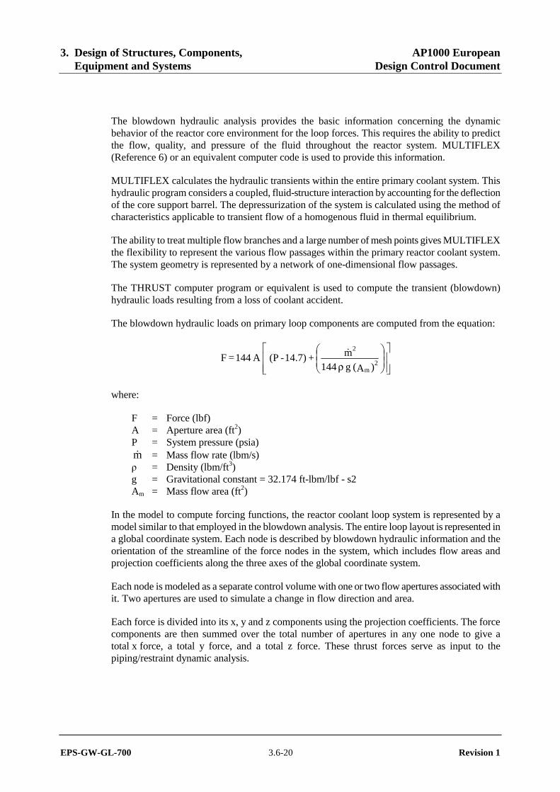
The blowdown hydraulic loads on primary loop components are computed from the equation:
⎥⎥⎦
⎤
⎢⎢⎣
⎡⎟⎟⎠
⎞⎜⎜⎝
⎛
ρ
)A( g 144m + 14.7) - (P A 144 = F
2m
2&
where:
F = Force (lbf) A = Aperture area (ft2) P = System pressure (psia) m& = Mass flow rate (lbm/s) ρ = Density (lbm/ft3) g = Gravitational constant = 32.174 ft-lbm/lbf - s2 Am = Mass flow area (ft2)
In the model to compute forcing functions, the reactor coolant loop system is represented by a model similar to that employed in the blowdown analysis. The entire loop layout is represented in a global coordinate system. Each node is described by blowdown hydraulic information and the orientation of the streamline of the force nodes in the system, which includes flow areas and projection coefficients along the three axes of the global coordinate system.
Each node is modeled as a separate control volume with one or two flow apertures associated with it. Two apertures are used to simulate a change in flow direction and area.
Each force is divided into its x, y and z components using the projection coefficients. The force components are then summed over the total number of apertures in any one node to give a total x force, a total y force, and a total z force. These thrust forces serve as input to the piping/restraint dynamic analysis.

3. Design of Structures, Components, AP1000 European Equipment and Systems Design Control Document
EPS-GW-GL-700 3.6-21 Revision 1
The THRUST code calculates forces the same way as the STHRUST code described in WCAP-8252 (Reference 7).
3.6.2.3 Dynamic Analysis Methods to Verify Integrity and Operability
This subsection describes the pipe rupture design criteria for auxiliary piping systems. Subsection 3.6.2.2 describes the analysis methods for thrust loadings. To mitigate each postulated pipe rupture, auxiliary piping systems required to maintain pressure boundary integrity or to provide for fluid flow are identified. The loadings on these systems may consist of jet impingement loads, transient motions at terminal end connections, or internal system depressurization loadings.
The application of leak-before-break analysis eliminates evaluation of postulated pipe ruptures in the primary coolant loop piping and selected piping systems of 6-inch (DN 150 mm) nominal size or larger. The piping system mechanical components and supports are designed for the effects of the remaining postulated pipe ruptures and leaks.
To confirm the continued integrity of the essential components and the engineered safety systems, consideration is given to the consequential effects of the pipe break to the extent that:
• The minimum performance capabilities of the engineered safety systems are not reduced below that required to protect against the postulated break.
• The containment leaktightness is not decreased below the design value if the break leads to a loss of coolant accident.
• Propagation of damage is limited in type or degree or both to the extent that:
– A pipe break that is not a loss of coolant accident, steam line break, or main feedwater break will not cause a loss of coolant accident or steam line or feedwater line break. Pipe breaks on the nonreactor side of a reactor coolant system pressure boundary may be assumed to cause a failure of the reactor side of the same pipe, provided the combined failures are evaluated for impact on system performance.
– A reactor coolant system pipe break will not cause a steam or feedwater system pipe break, and vice versa.
3.6.2.3.1 Jet Impingement
Analytical methods for the calculation of jet impingement forces are based on Moody, F. J. (Reference 5), NUREG/CR-2913 (Reference 1), and Section 7.3 of ANS-58.2-1988 (Reference 4). For piping systems this loading is a suddenly applied load that can have significant energy content. These loads are generally treated as statically applied constant loads.
Two separate structural evaluations are performed. For the short-term response, snubber supports are considered to be active and a dynamic load factor of 2 is used. For the longer-term response, snubber supports are considered inactive, and no dynamic load factor is used.
3. Design of Structures, Components, AP1000 European Equipment and Systems Design Control Document
EPS-GW-GL-700 3.6-22 Revision 1
If simplified static analysis is performed instead of a dynamic analysis, the preceding jet load (FT) is multiplied by a dynamic load factor. For an equivalent static analysis of the target structure, the jet impingement force is multiplied by a dynamic load factor of 1.2 to 2.0, depending upon the time variance of the jet load and the elastic/plastic behavior of the target. This factor assumes that the target can be represented as essentially a one-degree-of-freedom system.
3.6.2.3.2 Transient Motions at Terminal Ends
This loading is displacement limited and has a short duration of about 0.5 seconds. An example is the motions of the primary loop piping at the terminal end connection of the Class 1 pressurizer surge line piping due to a postulated pipe rupture in a Class 2 pipe connected to the steam generator.
When there are active in-line components in the piping system that must function to mitigate the postulated pipe rupture, dynamic structural analyses are performed for the terminal end motions. The calculated accelerations are evaluated to confirm the operability of the active in-line components. For piping systems with no active in-line components, static structural analyses with no dynamic amplification are performed for the terminal end motions.
These analyses may consider nonlinear geometric and material characteristics of the piping system.
3.6.2.3.3 Internal System Depressurization
This loading has a short duration of approximately 0.5 seconds and arises from rapidly traveling pressure waves in piping systems connected to the broken piping system. Two types of configurations are possible: systems without check valves and systems with check valves. In systems with check valves, the valve closure can increase the duration and magnitude of these loads.
An example of the former is the pressure waves in the Class 1 letdown line of the chemical and volume control system piping due to a postulated pipe rupture in a Class 1 pipe connected to the primary loop piping. An example of the latter is the closure of the feedwater check valve due to a postulated pipe rupture upstream of the valve.
For piping systems without closing check valves, there is little energy in the high-frequency depressurization loadings. These loadings are therefore not considered in the piping and support analysis.
For piping system with closing check valves, the magnitude of the loadings depends on the valve closure time, with shorter closing times generally causing higher loadings. For this loading the potential system failure mechanisms evaluated are: 1) excessive pipe and valve hoop stress; 2) tensile loads on the valve pressure boundary bolting; and 3) excessive distortion of the valve disc or seat.
The maximum internal pressure and the kinetic energy of the valve disc at the time of closure are used to verify the pressure boundary integrity of the piping and valve based on the preceding failure mechanisms. MULIFLEXSG is used to calculate the pressure and kinetic energy. The

3. Design of Structures, Components, AP1000 European Equipment and Systems Design Control Document
EPS-GW-GL-700 3.6-23 Revision 1
supports on these systems are designed in such a way that support failure will occur prior to local pipe pressure boundary failure at the support connection.
3.6.2.3.4 Pipe Whip Restraints
To satisfy varying requirements of available space, permissible pipe deflection, and equipment operability, the restraints are generally designed as a combination of an energy-absorbing element and a restraint structure suitable for the geometry required to pass the restraint load from the whipping pipe to the main building structure. The restraint structure is typically a structural steel frame or truss, and the energy-absorbing element is usually either stainless steel U-bars or energy-absorbing material.
3.6.2.3.4.1 Location of Pipe Whip Restraints
For purposes of determining pipe hinge length and thus locating the pipe whip restraints, the plastic moment of the pipe is determined in the following manner:
Mp = 1.1 zpSy
where:
zp = Plastic section modulus of pipe Sy = Yield stress at pipe operating temperature 1.1 = 10-percent factor to account for strain hardening.
Pipe whip restraints are located as close to the axis of the reaction thrust force as practicable. Pipe whip restraints are generally located so that a plastic hinge does not form in the pipe. If, because of physical limitations, pipe whip restraints are located so that a plastic hinge can form, the consequences of the whipping pipe and the jet impingement effect are further investigated. Lateral guides are provided where necessary to predict and control pipe motion.
Generally, pipe whip restraints are designed and located with sufficient clearances between the pipe and the restraint in such a way that they do not interact and cause additional piping stresses. A design hot position gap is provided that allows maximum predicted thermal, seismic, and seismic anchor movement displacements to occur without interaction.
Exception to this general criterion may occur when a pipe support and restraint are incorporated into the same structural steel frame, or when a zero design gap is required. In these cases, the pipe whip restraint is included in the piping analysis and designed to the requirements of pipe support structures for all loads except pipe break and designed to the requirements of pipe whip restraints when pipe break loads are included.
In general, the pipe whip restraints do not prevent the access required to conduct in-service inspection examination of piping welds. When the location of the restraint makes the piping welds inaccessible for in-service inspection, a portion of the restraint is designed to be removable to provide accessibility.
3. Design of Structures, Components, AP1000 European Equipment and Systems Design Control Document
EPS-GW-GL-700 3.6-24 Revision 1
3.6.2.3.4.2 Analysis and Design of Pipe Whip Restraints
The criteria for analysis and design of pipe whip restraints for postulated pipe break effects are provided in the following. These criteria are consistent with the guidelines in ANS-58.2-1988 (Reference 4).
• Pipe whip restraints are designed based on energy absorption principles by considering the elastic-plastic, strain-hardening behavior of the materials used.
• Non-energy absorbing portions of the pipe whip restraints are designed to the requirements of AISC N690 Code supplemented by the requirements given in subsection 3.8.4.5
• A rebound factor of 1.1 is applied to the jet thrust force.
• Except in cases where calculations are performed to verify that a plastic hinge is formed, the energy absorbed by the ruptured pipe is conservatively assumed to be zero. That is, the thrust force developed goes directly into moving the broken pipe and is not reduced by the force required to bend the pipe.
• Other structural members of the pipe whip restraints are designed for elastic response. A dynamic increase factor is used for those members that are designed to remain elastic.
• The criteria for allowable strain in a pipe whip restraint are dependent on the type of restraint. The following discussions address the types of restraints used and the allowable strain for each. Note -ε = allowable strain used in design, and δ = allowable crushable length used in design.
Stainless Steel U-Bar – This type of restraint consists of one or more U-shaped, upset-threaded rods of stainless steel looped around the pipe but not in contact with the pipe. This allows unimpeded pipe motion during seismic and thermal movement of the pipe. At rupture, the pipe moves against the U-bars, which absorb the kinetic energy of pipe motion by yielding plastically. Figure 3.6-1 shows a typical example of a U-bar restraint.
ε = 0.5εu
where:
εu = ultimate uniform strain of stainless steel (strain at ultimate stress)
Energy-Absorbing Material – This type of restraint consists of a crushable, stainless steel, internally honeycomb-shaped element designed to yield plastically under impact of the whipping pipe. A design hot position gap is provided between the pipe and the energy-absorbing material to allow unimpeded pipe motion during seismic and thermal pipe movements. Figure 3.6-2 shows a typical example of an energy-absorbing material restraint. The allowable capacity of crushable material shall be limited to 80 percent of its rated energy dissipating capacity as determined by dynamic testing, at loading rates within ± 50 percent of the specified design loading rate. The rated energy dissipating capacity shall be taken as not greater than the area under the
3. Design of Structures, Components, AP1000 European Equipment and Systems Design Control Document
EPS-GW-GL-700 3.6-25 Revision 1
load-deflection curve as illustrated in Figure 3.6.2-1 of NUREG-0800, Standard Review Plan, Section 3.6.2, Revision 2.
3.6.2.4 Protective Assembly Design Criteria
In addition to pipe whip restraints, other protective devices are designed to protect against the effects of postulated pipe ruptures. Barriers and shields are designed to protect against jet impingement. Guard pipes in the break exclusion zones provide additional confidence that pipes will not leak into the annulus between the containment vessel and the shield building.
3.6.2.4.1 Jet Impingement Barriers and Shields
Barriers and shields, constructed of either steel or concrete, are provided to protect essential equipment, including instrumentation, from the effects of jet impingement resulting from postulated pipe breaks. Barriers differ from shields in that they may also accept the impact of whipping pipes. Barriers and shields include walls, floors, and structures specifically designed to provide protection from postulated pipe breaks. Barrier and shield design is based on elastic methods and the elastic-plastic methods for dynamic analysis included in Biggs, J. M. (Reference 9). Design criteria and loading combinations are according to subsections 3.8.3 and 3.8.4.
3.6.2.4.2 Auxiliary Guardpipes
The use of guard pipes has been minimized by plant arrangement and routing of high-energy piping. Guard pipes in the containment annulus areas of the break exclusion zones are designed as described in subsection 3.6.2.1.1.4. Other guard pipes are designed and constructed to the same ASME rules as the enclosed process pipe.
3.6.2.5 Evaluation of Dynamic Effects of Pipe Ruptures
The preceding information provides the criteria and methods for the evaluation of the dynamic effects of pipe ruptures. The pipe rupture hazard analysis report (also referred to as the pipe break evaluation report) includes the following:
• Prepare a stress summary
• Identify pipe break locations in high energy piping
• Identify through-wall crack locations in high and moderate energy piping
• Identify and locate essential structures, systems, and components
• Evaluate consequences of pipe whip and jet impingement
For rooms with both high energy breaks and essential items, confirm that there is no adverse interaction between the essential items and the whipping pipe or jet.
The plant layout is modified as required to provide separation to protect essential systems.
3. Design of Structures, Components, AP1000 European Equipment and Systems Design Control Document
EPS-GW-GL-700 3.6-26 Revision 1
• Evaluate consequences of flooding, environment, and compartment pressurization
• Design and locate protective hardware
Prepare isometric piping sketches that identify the break locations, the basis for these locations and the protective hardware which mitigates the consequences of these breaks.
• Reconciliation of as-built condition
Pipe breaks that are larger than 1 inch (DN 25 mm) nominal diameter are evaluated for pipe whip and jet impingement. Lines that are located in a break exclusion zone or are qualified to leak-before-break are not evaluated for pipe whip and jet impingement effects on systems and components, except for the portions of the lines in the MSIV compartment adjacent to the main control room as noted in subsection 3.6.1.2.2.
Where these systems are qualified for mechanistic pipe break and pipe rupture loads prior to fabrication, the qualification is based on design information, not on as-built information. As-built information and the final configuration of valves and other equipment is used to verify the design analysis.
High Energy Break Locations
High energy break locations evaluated are on the nuclear island and in the turbine building for evaluation of the wall loadings in the south end of the turbine building adjacent to the main control room.
For ASME Class 1 piping terminal end locations are determined from the piping isometric drawings. Intermediate break locations depend on the ASME Code stress report fatigue analysis results. These results are not available at design certification. For the design of the AP1000, breaks are postulated at locations typically associated with a high cumulative fatigue usage factor. These locations are at valves, tees, and branch connections which have significant structural discontinuities. These locations are part of the as-built reconciliation as discussed in subsection 3.6.4.1. The following ASME Class 1 lines are evaluated to terminal end and intermediate high energy break locations if applicable.
Line Diameter (inches)
Pressurizer Spray 4 (101.6 mm) Automatic Depressurization Stage 1 4 (101.6 mm) Chemical and Volume Control Letdown 3 (76.2 mm) Chemical and Volume Control Makeup 3 (76.2 mm) Pressurizer Auxiliary Spray 2 (50.8 mm)
For ASME Class 2 and 3 piping, terminal end break locations are determined from the piping isometric drawings. The intermediate break locations depend on the stress level. The AP1000 ASME Class 2 and 3 lines do not have intermediate breaks based on the low stress. The following ASME Class 2 and 3 lines have terminal end high energy break locations.
3. Design of Structures, Components, AP1000 European Equipment and Systems Design Control Document
EPS-GW-GL-700 3.6-27 Revision 1
Line Diameter (inches)
Main Feedwater 16, 20 (406.4 mm, 508.0 mm) Startup Feedwater 6 (152.4 mm) Steam Generator Blowdown 4 (101.6 mm)
For B31.1 piping, terminal end break locations are determined from the piping isometric drawings. The intermediate break locations in seismically analyzed pipe depend on the stress level. The AP1000 ASME seismically analyzed B31.1 piping does not have intermediate breaks based on the low stress. For nonseismically analyzed high-energy ASME B31.1, intermediate breaks locations are postulated at each fitting.
Rooms subject to pressurization due to high energy pipe break are listed in Table 3.6-2 with the terminal end location.
Essential Systems and Components
In rooms that contain high energy pipe breaks, the systems and components that are needed to mitigate the postulated break and achieve a safe plant shutdown are identified. Rooms that contain both high energy pipe break locations and essential systems or components that must be protected are listed in Table 3.6-3. No high energy pipe break protection is required in other areas of the plant.
Essential Target Evaluation
To complete the essential target evaluation jet parameters, volumetric area of affected compartments, plant layout, and separating structures are considered. Parameters that determine the shape of the jet and the magnitude of the jet and thrust loads include pressure, temperature, and friction losses between the break and the reservoir. The volumetric area affected is determined by considering jet shape and loads at the postulated location of the breaks. Where an initial evaluation of essential targets indicated adverse effects, layout may be changed to relocate the target or postulated break. If necessary, the location of whip restraints and jet shields is established to protect essential systems and components. Essential equipment protected by pipe whip restraints or jet shields is listed in Table 3.6-3. The criteria for the break location postulated for evaluation of separating structures is outlined in subsection 3.6.1.3.2.
Verification of the Pipe Break Hazard Analysis
A pipe rupture hazard analysis is prepared based on the as-designed piping stress analyses and pipe whip restraint design information. The as-designed piping analysis is based on piping routings, layouts, and isometrics. Intermediate break locations are identified using the as-designed piping stress analysis, including the fatigue analysis required for ASME Code Class 1 piping. As-designed piping stress analysis information is used to confirm the location and configuration of pipe whip restraints and jet impingement shields. The information included in Tables 3.6-2 and 3.6-3 is updated and validated as part of the as-designed pipe rupture hazard analysis. Large leakage cracks in moderate energy pipes are evaluated for adverse effects as part of the pipe break hazard evaluation.

3. Design of Structures, Components, AP1000 European Equipment and Systems Design Control Document
EPS-GW-GL-700 3.6-28 Revision 1
The ASME Code, Section III, requires that each plant have a Design Report for the piping system that includes as-built information. Included in the Design Reports are the loads and loading combinations used in the analysis. Where mechanistic pipe break requirements are used to eliminate the evaluation of dynamic effects of pipe rupture in ASME Code, Section III, Class 1, 2, and 3 piping system, the basis for the exclusion is documented in the Design Report.
The final piping stress analyses, pipe whip restraint design, and as-built reconciliation of the pipe break hazard analysis is discussed in subsection 3.6.4.1. The final piping stress analysis includes design properties and characteristics of procured components selected to be included in the piping system that are not available for the as-designed evaluation. The as-built reconciliation is required prior to fuel loading and includes evaluation of the ASME Code fatigue analysis, pipe break dynamic loads, reconciliation to the certified design floor response spectra, confirmation of the reactor coolant loop time history seismic analyses, changes in support locations, preoperational testing, and construction deviations.
3.6.2.6 Evaluation of Flooding Effects from Pipe Failures
The effect of flooding due to high and moderate energy pipe failures on essential systems and components is described in Section 3.4.
3.6.2.7 Evaluation of Spray Effects from High- and Moderate-energy Through-wall Cracks
Essential systems and components are evaluated for the potential effects of spray from high- and moderate-energy through-wall cracks. Spray effects are assumed to be limited to the compartment where the pipe failure occurs. The spray is assumed to wet unprotected components in the compartment. It is further assumed the spray does not damage non-electrical passive components, including piping, ducts, valve bodies, or mechanical components of valve operators. Spray may cause failure of electrical components not designed to withstand wetting. Components protected by NEMA 4 or NEMA 12 enclosures are not affected by spray effects.
The safe shutdown components inside containment are subject to wetting from design basis events inside containment. These conditions bound the effects of spray from moderate energy cracks. Sensitive components are qualified for this environment as described in Section 3.11.
The doors to the auxiliary Class 1E battery rooms are normally closed, so spray cannot affect the batteries if fire fighting activities or a pipe crack were to occur in the corridor. If fire fighting activities were to occur in a particular room, all of the equipment is assumed inoperable due to the fire, therefore, no further spray effects need be considered. The containment isolation valves subject to spray and the safe shutdown components in the main steam tunnels are provided with spray protection. The sensitive components of the main control room emergency habitability system are protected from spray effects.
3.6.3 Leak-before-break Evaluation Procedures
This subsection describes the design basis for mechanistic pipe break (leak-before-break) evaluation of high-energy piping systems.
3. Design of Structures, Components, AP1000 European Equipment and Systems Design Control Document
EPS-GW-GL-700 3.6-29 Revision 1
Mechanistic pipe break evaluations demonstrate that for piping lines meeting the criteria, sudden catastrophic failure of the pipe is not credible. It is demonstrated that piping that satisfies the criteria leaks at a detectable rate from postulated flaws prior to growth of the flaw to a size that would fail because applied loads resulting from normal conditions, anticipated transients, and a postulated safe shutdown earthquake.
The use of mechanistic pipe break criteria represents a higher level of confidence of the integrity of piping systems based on additional criteria compared to the existing high level of integrity provided by the requirements of the ASME Code. Evaluations of the mechanistic pipe break criteria are commonly called leak-before-break evaluations.
The use of mechanistic pipe break criteria permits the elimination of the evaluation of dynamic effects of sudden circumferential and longitudinal pipe breaks in the design basis analysis of structures, systems, and components. General Design Criterion 4 of Appendix A, 10 CFR Part 50 allows the use of analyses to eliminate from the design basis the dynamic effects of pipe ruptures.
Without the application of mechanistic pipe break criteria, the dynamic effects are evaluated for pipe ruptures postulated at locations defined in subsection 3.6.2. Dynamic effects include jet impingement, pipe whip, jet reaction forces on other portions of the piping and components, subcompartment pressurization including reactor cavity asymmetric pressurization transients, pump overspeed and traveling pressure waves from the depressurization of the system.
Incorporating leak-before-break criteria and guidelines into the design process maximizes the benefits of applying mechanistic pipe break. Eliminating the dynamic effects permits minimizing the size and number of protective structures and eliminates the use of pipe whip restraints. This permits design optimization and avoids obstruction of pipe welds for in-service inspection by protective structures and restraints.
High-energy ASME Code Section III piping that is evaluated to the leak-before-break criteria is identified in Appendix 3E. This applies to the main steam piping as follows. The main steam piping from the steam generator outlet nozzle to the anchor downstream of the isolation valve is analyzed for applicable loadings including the safe shutdown earthquake. This anchor is at the exterior wall of the auxiliary building. The portion of this piping from the containment penetration flued head inboard weld to the above anchor satisfies the break exclusion zone requirements described in subsection 3.6.2. The portion of this piping from the steam generator outlet nozzle to flued head inboard weld is evaluated to the leak-before-break criteria. High-energy piping that does not satisfy the leak-before-break criteria is designed to the requirements discussed in subsections 3.6.1 and 3.6.2.
The piping to which mechanistic pipe break is applied is analyzed to demonstrate that the piping has leak-before-break characteristics. The leak-before-break analysis is either a fracture-mechanics based stability analysis or a plastic-instability limit load analysis as appropriate. The analysis combines normal and abnormal (including seismic) loads to determine a critical crack size for a postulated through-wall crack. The critical crack size is compared to the size of a leakage crack for which, with appropriate margin, detection is certain. When the critical crack size is sufficiently larger than the leakage crack size the leak-before-break requirements are satisfied.
3. Design of Structures, Components, AP1000 European Equipment and Systems Design Control Document
EPS-GW-GL-700 3.6-30 Revision 1
Mechanistic pipe break is not used for purposes of specifying non-structural design criteria for emergency core cooling, containment systems, or other non-structural engineered safety features, or for the evaluation of environmental effects including spray wetting, humidity, and adverse reactions with chemicals in the coolant. This includes piping for which leak-before-break is demonstrated.
A bounding analysis is performed for each piping system. The bounding analysis is applied as discussed in subsection 3.6.4.2 to verify that the as-built piping satisfies the requirements for leak-before-break.
3.6.3.1 Application of Mechanistic Pipe Break Criteria
Piping systems to which mechanistic pipe break are applied are high integrity systems with well understood loading combinations and conditions. The piping systems to which it is applied satisfy the requirements of the ASME Code, Section III. ASME Code requirements also apply to the pre-service and in-service inspection which confirm continued integrity.
The mechanistic pipe break approach is applicable to high-energy piping provided plant design, operating experience, tests, or analyses have indicated low probability of failure from effects of intergranular stress corrosion cracking, water hammer, steam hammer, fatigue (thermal or mechanical), or erosion.
The plant design and operating features permit the application of the mechanistic pipe break approach. The piping to which the leak-before-break criteria is applied is evaluated for fatigue due to cyclic loads as required by the appropriate requirements of the ASME Code.
The piping in the AP1000 does not operate at temperatures for which creep or creep fatigue must be considered.
The reactor coolant loop piping, branch lines, and other lines in contact with reactor coolant are fabricated of austenitic stainless steel, which is very resistant to erosion and corrosion in typical reactor coolant chemistries and flow rates. Intergranular stress corrosion cracking has not been associated with reactor coolant piping in pressurized water reactors.
The design of the reactor coolant loop is not conducive to the generation of water hammer loads. The reactor coolant loop does not have any valves that could result in a water hammer due to rapid valve closure. The steam bubble in the pressurizer is not subject to the introduction of a large volume of cold water sufficient to result in a bubble collapse water hammer.
The design and component selection of reactor coolant branch lines and other lines evaluated for mechanistic pipe break follow design guidelines intended to minimize the potential for water hammer. Comparison of the AP1000 piping to the screening criteria in Subsection 5.29 of NUREG/CR-6519 (Reference 13) demonstrates that there is not a significant potential for water hammer in the leak-before-break piping.
Thermal stratification of water in stagnant or slowly flowing lines can result in thermal fatigue in a pipe. The piping and system design requirements for AP1000 address the potential for thermal
3. Design of Structures, Components, AP1000 European Equipment and Systems Design Control Document
EPS-GW-GL-700 3.6-31 Revision 1
stratification. For additional information of thermal stratification, see subsections 3.9.3, 5.4.3, and 5.4.5.
The composition of the main steam lines has been selected to minimize the potential for erosion and corrosion. The main steam lines are fabricated from SA335 Grade P11 Alloy steel, which is composed of sufficient levels of chromium to preclude erosion and corrosion mechanisms. The main steam lines are not subject to water hammer or thermal stratification by the nature of the fluid transported.
The steam line is protected from being filled with water due to steam generator overfill by implementation of operating instructions or isolation requirements included in the protection system logic or both. See Section 7.3 for information on the protection system design to prevent overfill.
In addition to requirements on the design, fabrication, and inspection of the piping systems, the application of mechanistic pipe break requires a qualified leak detection capability. Leak detection systems inside containment meet the guidelines of Regulatory Guide 1.45. See subsection 5.2.5 for a discussion of the leak detection system for the reactor coolant system and connected piping.
3.6.3.2 Design Criteria for Leak-before-Break
The methods and criteria to evaluate leak-before-break in the AP1000 are consistent with the guidance in NUREG-1061 (Reference 11) and Draft Standard Review Plan 3.6.3 (Reference 12). The application of the mechanistic pipe break in AP1000 requires that the following design requirements are met.
• Pre-service inspection of welds is required.
• For ASME Code Class 1, Class 2, and Class 3 systems for which leak-before break is demonstrated, the ASME Code, Section III and Section XI preservice and inservice inspection requirements will provide for the integrity of each system. The weld and welder qualification, and weld inspection requirements for ASME Code, Section III, Class 3 leak-before-break lines are equivalent to the requirements for Class 2. The inservice inspection requirement for each Class 3 leak-before-break line includes a volumetric inspection equivalent to the requirements for Class 2 for the weld at or closest to the high stress location.
• Inservice inspection and testing of snubbers (if used) are performed to provide for a low snubber failure rate.
• For the maximum stress due to steady-state vibration refer to subsection 3.9.2.
• The leak-before-break bounding analysis curves are developed for each applicable piping system. The bounding analysis methods are described in Appendix 3B. These curves give the design guidance to satisfy the stress limits and leak-before-break acceptance criteria. The highest stressed point (critical location) determined from the piping stress analysis is compared to the bounding analysis curve and has to fall on or under the curve. The points on or under the bounding analysis curve satisfy the requirements for leak-before-break.
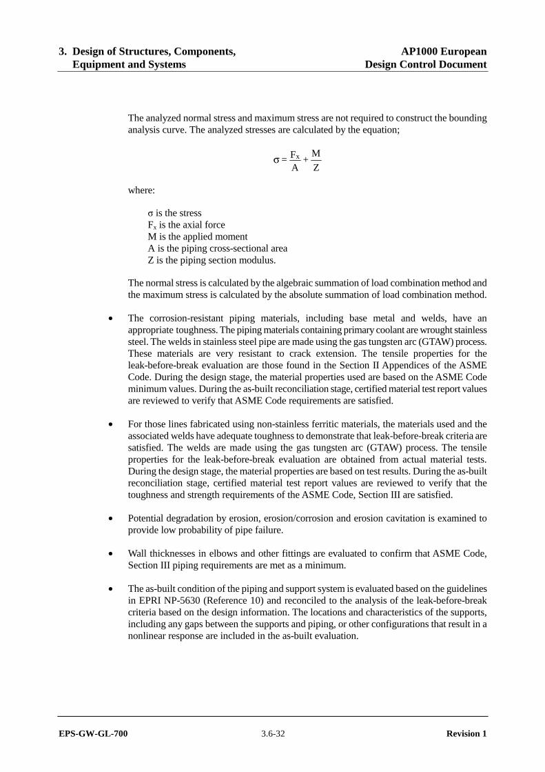
3. Design of Structures, Components, AP1000 European Equipment and Systems Design Control Document
EPS-GW-GL-700 3.6-32 Revision 1
The analyzed normal stress and maximum stress are not required to construct the bounding analysis curve. The analyzed stresses are calculated by the equation;
Z
M +
AF = xσ
where:
σ is the stress Fx is the axial force M is the applied moment A is the piping cross-sectional area Z is the piping section modulus.
The normal stress is calculated by the algebraic summation of load combination method and the maximum stress is calculated by the absolute summation of load combination method.
• The corrosion-resistant piping materials, including base metal and welds, have an appropriate toughness. The piping materials containing primary coolant are wrought stainless steel. The welds in stainless steel pipe are made using the gas tungsten arc (GTAW) process. These materials are very resistant to crack extension. The tensile properties for the leak-before-break evaluation are those found in the Section II Appendices of the ASME Code. During the design stage, the material properties used are based on the ASME Code minimum values. During the as-built reconciliation stage, certified material test report values are reviewed to verify that ASME Code requirements are satisfied.
• For those lines fabricated using non-stainless ferritic materials, the materials used and the associated welds have adequate toughness to demonstrate that leak-before-break criteria are satisfied. The welds are made using the gas tungsten arc (GTAW) process. The tensile properties for the leak-before-break evaluation are obtained from actual material tests. During the design stage, the material properties are based on test results. During the as-built reconciliation stage, certified material test report values are reviewed to verify that the toughness and strength requirements of the ASME Code, Section III are satisfied.
• Potential degradation by erosion, erosion/corrosion and erosion cavitation is examined to provide low probability of pipe failure.
• Wall thicknesses in elbows and other fittings are evaluated to confirm that ASME Code, Section III piping requirements are met as a minimum.
• The as-built condition of the piping and support system is evaluated based on the guidelines in EPRI NP-5630 (Reference 10) and reconciled to the analysis of the leak-before-break criteria based on the design information. The locations and characteristics of the supports, including any gaps between the supports and piping, or other configurations that result in a nonlinear response are included in the as-built evaluation.
3. Design of Structures, Components, AP1000 European Equipment and Systems Design Control Document
EPS-GW-GL-700 3.6-33 Revision 1
• Adjacent structures and components are designed for the safe shutdown earthquake event to provide low probability of indirect pipe failure.
• The piping supports are anchored to reinforced concrete structures, to concrete-filled steel plate structures, or to steel structures anchored to these types of structures. Piping is not supported by masonry block walls.
3.6.3.3 Analysis Methods and Criteria
The methods used to develop the bounding analysis curves are described in Appendix 3B. Development of the bounding analysis curves provides an evaluation method that is consistent with NRC requirements and guidance. The calculation method and computer codes used for AP1000 are benchmarked to test data and have been previously accepted by the NRC for leak-before-break evaluations in operating nuclear power plants.
Analyzable sections run from one terminal end or anchor to another terminal end or anchor. A terminal end is typically a connection to a larger pipe or a component. For the structural analysis, a normally closed valve between pressurized and unpressurized portions of a line is not considered a terminal end. Figure 3.6-3 is a schematic of a portion of a piping system that illustrates the meaning of analyzable segments. In the figure the analyzable portion of the pipe runs from point A to point D.
The leak-before-break evaluation is based on a fracture mechanics stability analysis comparing the selected leakage crack to the critical crack size. The following discussion outlines the analysis method.
The development of leak-before-break bounding analysis curves assume that circumferentially oriented postulated cracks are limiting. Stability is established by analyzing through-wall flaws.
Leakage Flaw
Through-wall flaws in candidate leak-before break piping systems are postulated. The size of the postulated flaws are large enough so that the leakage is detectable with adequate margin, using 10 times the minimum installed leak detection capability when the pipes are subjected to normal operational loads combining by algebraic sum method. That is, the size of the leakage flaw postulated would be expected to have a leak rate 10 times the size of the rated leak rate detection capability.
As noted in subsection 5.2.5, the rated capability of the leak detection systems for the primary coolant inside containment is 0.5 gpm (0.11 m3/hr) in one hour. The methods used to detect leakage are described in subsection 5.2.5.3. The methods used for primary coolant are the containment sump level, inventory balance, and containment atmosphere radiation. The method used to detect leakage from the main steam line inside containment is the containment sump level. Containment air cooler condensate flow, and containment atmosphere pressure, temperature, and humidity also provide an indication of possible leakage.
3. Design of Structures, Components, AP1000 European Equipment and Systems Design Control Document
EPS-GW-GL-700 3.6-34 Revision 1
Stability and Critical Flaw Sizes
The local and global failure mechanisms are evaluated, as appropriate, to provide margin on flaw size and load. The local mode of failure addresses crack tip behavior: blunting, initiation, extension, and instability. The local failure mechanism is evaluated for ferritic steel piping systems using the J-integral method. The global mode of failure addresses the behavior of the net section: initial yielding, strain hardening, and plastic hinge formation. The global failure mechanism (limit load method) is evaluated for stainless steel piping with no cast material and GTAW welding. From these evaluations a critical crack size is determined. That is, a crack larger than the critical crack size would have unstable growth characteristics.
Acceptance Standards
The results of the preceding evaluations are compared to show that the critical flaw size, which is shown to be stable when the maximum loads are combined based on individual absolute values, is at least twice the size (to satisfy margin of 2 on flaw size) of the leakage flaw size. To satisfy a margin on load of 1.0, the maximum loads are combined using absolute summation of individual values. The maximum loads are described in Appendix 3B subsection 3B.3.3.
Bounding Analyses
Evaluations are provided for each different combination of material type, pipe size, pressure, and temperature. These evaluations are used to develop a set of curves of maximum faulted stress versus the corresponding normal stress that satisfy the criteria for leak-before-break. These curves are used in the design of the piping systems and will be used to verify that the as-built piping satisfies the requirements for leak-before-break as discussed in subsection 3.6.4.2.
3.6.3.4 Documentation of Leak-before-Break Evaluations
The leak-before-break evaluation is used to support the elimination of dynamic effects of pipe breaks from the loading conditions for the piping analysis. An evaluation of leak-before-break using the as-built configuration of the piping system and supports is required as part of the Design Report (also referred to as LBB evaluation report where applicable) of the as-built configuration required to meet ASME Code requirements and LBB criteria. Appendix 3B contains a discussion of the bounding analysis methods for the leak-before-break evaluation.
The analysis methods, criteria, and loads used for evaluation of stress in piping systems are outlined in subsections 3.7.3 and 3.9.3.
3.6.4 Combined License Information
3.6.4.1 Pipe Break Hazard Analysis
The Combined License information requested in this subsection has been partially addressed in APP-GW-GLR-021 (Reference 14) and APP-GW-GLR-074 (Reference 16), and the applicable changes are incorporated into the DCD. Additional work is required by the Combined License

3. Design of Structures, Components, AP1000 European Equipment and Systems Design Control Document
EPS-GW-GL-700 3.6-35 Revision 1
holder to address the aspects of the Combined License information requested in this subsection as delineated in the two following paragraphs:
The pipe rupture hazard evaluation (for pipe whip and jet impingement) was performed for the AP1000 Design Certification. The purpose of this evaluation was to identify potential targets and determine the method of protection to be used for safety-related targets located in the vicinity of postulated high-energy pipe breaks at terminal ends. In addition, the room locations of pipe whip restraints were identified.
As explained in APP-GW-GLR-021, which discusses AP1000 As-Built COL Information Items, the timing of the reconciliation of the as-built pipe break hazard analysis is such that the reconciliation cannot be provided by an applicant for a COL. This reconciliation will be done prior to operation of the plant. An as-designed pipe rupture hazard analysis based on the as-designed pipe analysis is prepared to update and validate the information provided in APP-GW-GLR-074 (Reference 16).
The following words represent the original Combined License Information Item commitment, which has been addressed as discussed above:
Combined License applicants referencing the AP1000 certified design will complete the final pipe whip restraint design and address as-built reconciliation of the pipe break hazards analysis in accordance with the criteria outlined in subsections 3.6.1.3.2 and 3.6.2.5. The as-built pipe rupture hazard analysis will be documented in an as-built Pipe Rupture Hazards Analysis Report.
After a Combined License is issued, the following activities will be completed by the COL holder:
Combined License applicants referencing the AP1000 certified design will complete the design of pipe whip restraints and jet shields at the locations specified in the as-designed pipe rupture hazard evaluation. These design efforts to be completed by the COL holder will be based on the information provided in the as-designed pipe rupture hazard evaluation. The as-designed pipe rupture hazard evaluation, including identification of locations where pipe whip restraints and jet shields are required, is prepared on a generic basis to address COL applications referencing the AP1000 Design Certification.
The final pipe whip restraint and jet shield design includes the properties and characteristics of procured components connected to the piping, components, and walls at identified break and target locations. The final design will be completed prior to fabrication and installation of the piping and connected components. The as-built reconciliation of the pipe rupture hazards evaluation whip restraint and jet shield design, in accordance with the criteria outlined in subsections 3.6.1.3.2 and 3.6.2.5, will be completed prior to fuel load.
3. Design of Structures, Components, AP1000 European Equipment and Systems Design Control Document
EPS-GW-GL-700 3.6-36 Revision 1
3.6.4.2 Leak-before-Break Evaluation of as-Designed Piping
The Combined License information requested in this subsection has been completely addressed in APP-GW-GLR-022 (Reference 15), and the applicable changes are incorporated into the DCD. No additional work is required by the Combined License applicant.
The following words represent the original Combined License Information Item commitment, which has been addressed as discussed above:
Combined License applicants referencing the AP1000 certified design will complete the leak-before-break evaluation by comparing the results of the as-designed piping stress analysis with the bounding analysis curves documented in Appendix 3B. The Combined License applicant may perform leak-before-break evaluation for a specific location and loading for cases not covered by the bounding analysis curves. Successfully satisfying the bounding analysis curve limits in Appendix 3B may necessitate lowering the detection limit for unidentified leakage in containment from 0.5 gpm to 0.25 gpm. If so, the Combined License holder shall provide a leak detection system capable of detecting a 0.25 gpm leak within 1 hour and shall modify appropriate portions of the DCD including subsections 5.2.5, 3.6.3.3, 11.2.4.1, Technical Specification 3.4.7 (and Bases), Technical Specification Bases B3.4.9, and Technical Specification 3.7.8 (and Bases). The leak-before-break evaluation will be documented in a leak-before-break evaluation report.
3.6.4.3 Leak-before-Break Evaluation of as-Built Piping
Not used.
3.6.4.4 Primary System Inspection Program for Leak-before-Break Piping
Combined License applicants referencing the AP1000 certified design will develop an inspection program for piping systems qualified for leak-before-break. The inspection program will consider the operating experience of the materials used in the AP1000 piping systems qualified for leak-before-break, and will include augmented inspection plans and evaluation criteria consistent with those measures imposed on or adopted by operating PWRs as part of the ongoing resolution of concerns regarding the potential for PWSCC in operating plants. The AP1000 inspection program will be consistent with the inspection program adopted for operating PWRs that use Alloy 690, 52, and 152 in approved leak-before-break applications.
3.6.5 References
1. NUREG/CR-2913, “Two-Phase Jet Loads,” January 1983.
2. WCAP-8077 (Proprietary) and WCAP-8078 (Nonproprietary), “Ice Condenser Containment Pressure Transient Analysis Methods,” March 1973.
3. ASME/ANSI-B31.1-1989 Edition, “Power Piping,” including 1989 Addendum.
4. ANSI/ANS-58.2-1988, “Design Bases for Protection of Light Water Nuclear Power Plants Against Effects of Postulated Pipe Rupture.”
3. Design of Structures, Components, AP1000 European Equipment and Systems Design Control Document
EPS-GW-GL-700 3.6-37 Revision 1
5. Moody, F. J., Fluid Reaction and Impingement Loads, paper presented at the ASCE Specialty Conference, Chicago, December 1973.
6. “MULTIFLEX, A FORTRAN-IV Computer Program for Analyzing Thermal-Hydraulic-Structure System Dynamics,” WCAP-8708 (Proprietary) and WCAP-8709 (Nonproprietary), February 1976.
7. WCAP-8252, “Documentation of Selected Westinghouse Structural Analysis Computer Codes,” Revision 1, May 1977.
8. Not used.
9. Biggs, J. M., Introduction to Structural Dynamics, McGraw-Hill Book Company, New York, 1964.
10. EPRI NP-5630, “Guidelines for Piping System Reconciliation” (NCIG-05, Revision 1), May 1988.
11. NUREG-1061, Volume 3, Report of the U. S. Nuclear Regulatory Commission Piping Review Committee, Evaluation of Potential for Pipe Breaks, November 1984.
12. Standard Review Plan 3.6.3, “Leak Before Break Evaluation Procedures,” Federal Register, Volume 52, Number 167, Friday, August 28, 1987; Notice (Public Comment Solicited), pp. 32626-32633.
13. NUREG/CR-6519, Screening Reactor Steam/Water Systems for Water Hammer, November 1996.
14. APP-GW-GLR-021, “AP1000 As-Built COL Information Items,” Westinghouse Electric Company LLC.
15. APP-GW-GLR-022, “AP1000 Leak-Before-Break Evaluation of As-Designed Piping,” Westinghouse Electric Company LLC.
16. APP-GW-GLR-074, “Pipe Break Hazards Analysis,” Westinghouse Electric Company LLC.
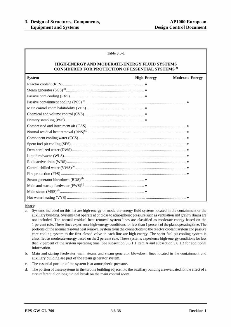
3. Design of Structures, Components, AP1000 European Equipment and Systems Design Control Document
EPS-GW-GL-700 3.6-38 Revision 1
Table 3.6-1
HIGH-ENERGY AND MODERATE-ENERGY FLUID SYSTEMS CONSIDERED FOR PROTECTION OF ESSENTIAL SYSTEMS(a)
System High-Energy Moderate-Energy
Reactor coolant (RCS) ................................................................................... •
Steam generator (SGS)(b)................................................................................ •
Passive core cooling (PXS)............................................................................ •
Passive containment cooling (PCS)(c) ....................................................................................................... •
Main control room habitability (VES) ........................................................... •
Chemical and volume control (CVS) ............................................................. •
Primary sampling (PSS)................................................................................. •
Compressed and instrument air (CAS)...................................................................................................... •
Normal residual heat removal (RNS)(a) ..................................................................................................... •
Component cooling water (CCS) .............................................................................................................. •
Spent fuel pit cooling (SFS)...................................................................................................................... •
Demineralized water (DWS)..................................................................................................................... •
Liquid radwaste (WLS)............................................................................................................................. •
Radioactive drain (WRS).......................................................................................................................... •
Central chilled water (VWS)(a).................................................................................................................. •
Fire protection (FPS) ................................................................................................................................ •
Steam generator blowdown (BDS)(d).............................................................. •
Main and startup feedwater (FWS)(d) ............................................................. •
Main steam (MSS)(d) ...................................................................................... •
Hot water heating (VYS) ................................................................................ ......................................... •
Notes: a. Systems included on this list are high-energy or moderate-energy fluid systems located in the containment or the
auxiliary building. Systems that operate at or close to atmospheric pressure such as ventilation and gravity drains are not included. The normal residual heat removal system lines are classified as moderate-energy based on the 1 percent rule. These lines experience high-energy conditions for less than 1 percent of the plant operating time. The portions of the normal residual heat removal system from the connections to the reactor coolant system and passive core cooling system to the first closed valve in each line are high energy. The spent fuel pit cooling system is classified as moderate energy based on the 2 percent rule. These systems experience high-energy conditions for less than 2 percent of the system operating time. See subsection 3.6.1.1 Item A and subsection 3.6.1.2 for additional information.
b. Main and startup feedwater, main steam, and steam generator blowdown lines located in the containment and auxiliary building are part of the steam generator system.
c. The essential portion of the system is at atmospheric pressure.
d. The portion of these systems in the turbine building adjacent to the auxiliary building are evaluated for the effect of a circumferential or longitudinal break on the main control room.
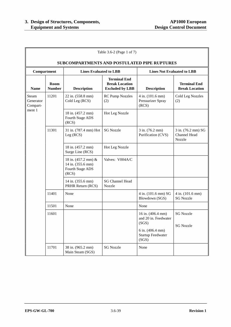
3. Design of Structures, Components, AP1000 European Equipment and Systems Design Control Document
EPS-GW-GL-700 3.6-39 Revision 1
Table 3.6-2 (Page 1 of 7)
SUBCOMPARTMENTS AND POSTULATED PIPE RUPTURES
Compartment Lines Evaluated to LBB Lines Not Evaluated to LBB
Name Room
Number Description
Terminal End Break Location
Excluded by LBB Description Terminal End
Break Location
22 in. (558.8 mm) Cold Leg (RCS)
RC Pump Nozzles (2)
4 in. (101.6 mm) Pressurizer Spray (RCS)
Cold Leg Nozzles (2)
11201
18 in. (457.2 mm) Fourth Stage ADS (RCS)
Hot Leg Nozzle
31 in. (787.4 mm) Hot Leg (RCS)
SG Nozzle 3 in. (76.2 mm) Purification (CVS)
3 in. (76.2 mm) SG Channel Head Nozzle
18 in. (457.2 mm) Surge Line (RCS)
Hot Leg Nozzle
18 in. (457.2 mm) & 14 in. (355.6 mm) Fourth Stage ADS (RCS)
Valves: V004A/C
11301
14 in. (355.6 mm) PRHR Return (RCS)
SG Channel Head Nozzle
11401 None 4 in. (101.6 mm) SG Blowdown (SGS)
4 in. (101.6 mm) SG Nozzle
Steam Generator Compart-ment 1
11501 None None
11601 16 in. (406.4 mm) and 20 in. Feedwater (SGS)
6 in. (406.4 mm) Startup Feedwater (SGS)
SG Nozzle
SG Nozzle
11701 38 in. (965.2 mm) Main Steam (SGS)
SG Nozzle None
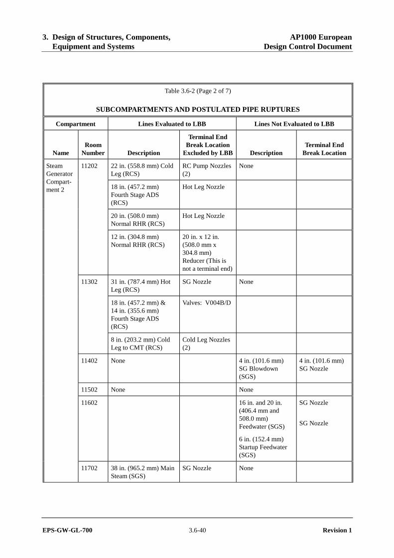
3. Design of Structures, Components, AP1000 European Equipment and Systems Design Control Document
EPS-GW-GL-700 3.6-40 Revision 1
Table 3.6-2 (Page 2 of 7)
SUBCOMPARTMENTS AND POSTULATED PIPE RUPTURES
Compartment Lines Evaluated to LBB Lines Not Evaluated to LBB
Name Room
Number Description
Terminal End Break Location
Excluded by LBB Description Terminal End
Break Location
22 in. (558.8 mm) Cold Leg (RCS)
RC Pump Nozzles (2)
None
18 in. (457.2 mm) Fourth Stage ADS (RCS)
Hot Leg Nozzle
20 in. (508.0 mm) Normal RHR (RCS)
Hot Leg Nozzle
11202
12 in. (304.8 mm) Normal RHR (RCS)
20 in. x 12 in. (508.0 mm x 304.8 mm) Reducer (This is not a terminal end)
31 in. (787.4 mm) Hot Leg (RCS)
SG Nozzle None
18 in. (457.2 mm) & 14 in. (355.6 mm) Fourth Stage ADS (RCS)
Valves: V004B/D
11302
8 in. (203.2 mm) Cold Leg to CMT (RCS)
Cold Leg Nozzles (2)
11402 None 4 in. (101.6 mm) SG Blowdown (SGS)
4 in. (101.6 mm) SG Nozzle
Steam Generator Compart-ment 2
11502 None None
11602 16 in. and 20 in. (406.4 mm and 508.0 mm) Feedwater (SGS)
6 in. (152.4 mm) Startup Feedwater (SGS)
SG Nozzle
SG Nozzle
11702 38 in. (965.2 mm) Main Steam (SGS)
SG Nozzle None

3. Design of Structures, Components, AP1000 European Equipment and Systems Design Control Document
EPS-GW-GL-700 3.6-41 Revision 1
Table 3.6-2 (Page 3 of 7)
SUBCOMPARTMENTS AND POSTULATED PIPE RUPTURES
Compartment Lines Evaluated to LBB Lines Not Evaluated to LBB
Name Room
Number Description
Terminal End Break Location
Excluded by LBB Description Terminal End
Break Location
31 in. (787.4 mm) Hot Leg (RCS)
Reactor Vessel Nozzles (2)
None
22 in. (558.8 mm) Cold Leg (RCS)
Reactor Vessel Nozzles (4)
Reactor Vessel Nozzle Area
11205
8 in. (203.2 mm) Direct Vessel Injection (RCS)
Reactor Vessel Nozzles (2)
8 in. (203.2 mm) Accumulator Injection (PXS)
Accumulator Nozzle
None
8 in. (203.2 mm) CMT Injection (PXS)
CMT Nozzle
6 in. (152.4 mm) Line from Normal RHR (RNS)
Valve: V017A
PXS Valve and Accumulator Room A
11206
8 in. (203.2 mm) Line from IRWST (PXS)
Valves: V125A & V123A
6 in. (152.4 mm) Line from Normal RHR (RNS)
Valve: V017B None PXS Valve Room B
11207 PXS
8 in. (203.2 mm) Line from IRWST (PXS)
Valves: V125B & V123B
8 in. (203.2 mm) Accumulator Injection (PXS)
Accumulator Nozzle
None Accumulator Room B
11207 ACCUM
8 in. (203.2 mm) CMT Injection (PXS)
CMT Nozzle
None 3 in. (76.2 mm) Line from Regen HX to SG 01 (CVS)
Anchor to Wall Vertical Access
11204
3 in. (76.2 mm) Purification from Cold Leg to Regen HX (CVS)
Anchor to Wall
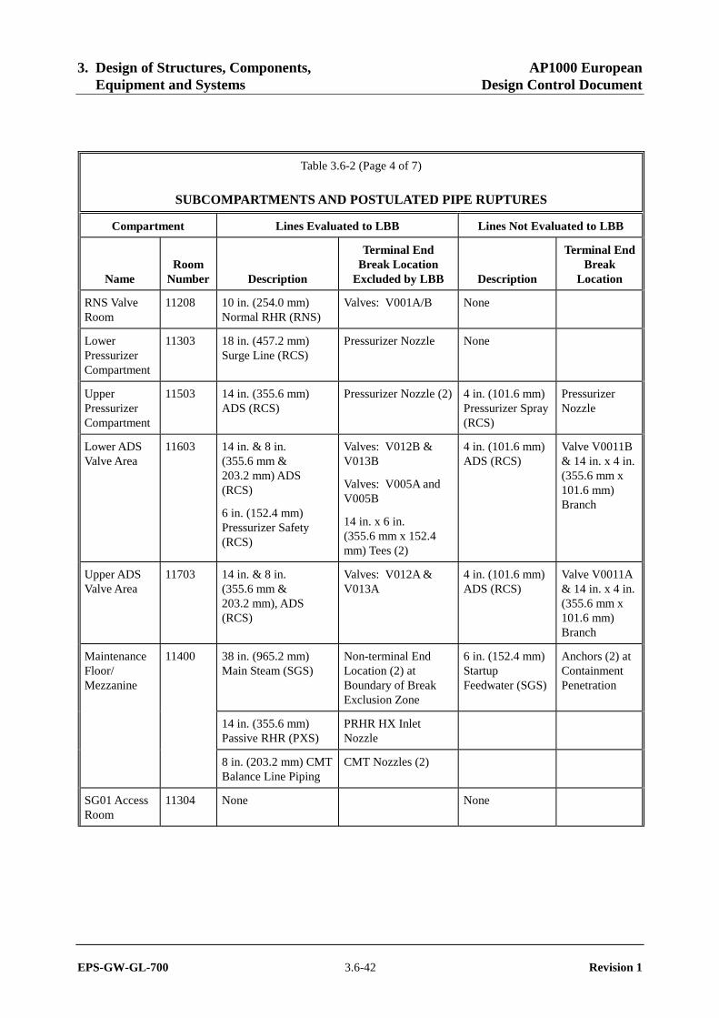
3. Design of Structures, Components, AP1000 European Equipment and Systems Design Control Document
EPS-GW-GL-700 3.6-42 Revision 1
Table 3.6-2 (Page 4 of 7)
SUBCOMPARTMENTS AND POSTULATED PIPE RUPTURES
Compartment Lines Evaluated to LBB Lines Not Evaluated to LBB
Name Room
Number Description
Terminal End Break Location
Excluded by LBB Description
Terminal End Break
Location
RNS Valve Room
11208 10 in. (254.0 mm) Normal RHR (RNS)
Valves: V001A/B None
Lower Pressurizer Compartment
11303 18 in. (457.2 mm) Surge Line (RCS)
Pressurizer Nozzle None
Upper Pressurizer Compartment
11503 14 in. (355.6 mm) ADS (RCS)
Pressurizer Nozzle (2) 4 in. (101.6 mm) Pressurizer Spray (RCS)
Pressurizer Nozzle
Lower ADS Valve Area
11603 14 in. & 8 in. (355.6 mm & 203.2 mm) ADS (RCS)
6 in. (152.4 mm) Pressurizer Safety (RCS)
Valves: V012B & V013B
Valves: V005A and V005B
14 in. x 6 in. (355.6 mm x 152.4 mm) Tees (2)
4 in. (101.6 mm) ADS (RCS)
Valve V0011B & 14 in. x 4 in. (355.6 mm x 101.6 mm) Branch
Upper ADS Valve Area
11703 14 in. & 8 in. (355.6 mm & 203.2 mm), ADS (RCS)
Valves: V012A & V013A
4 in. (101.6 mm) ADS (RCS)
Valve V0011A & 14 in. x 4 in. (355.6 mm x 101.6 mm) Branch
38 in. (965.2 mm) Main Steam (SGS)
Non-terminal End Location (2) at Boundary of Break Exclusion Zone
6 in. (152.4 mm) Startup Feedwater (SGS)
Anchors (2) at Containment Penetration
14 in. (355.6 mm) Passive RHR (PXS)
PRHR HX Inlet Nozzle
Maintenance Floor/ Mezzanine
11400
8 in. (203.2 mm) CMT Balance Line Piping
CMT Nozzles (2)
SG01 Access Room
11304 None None
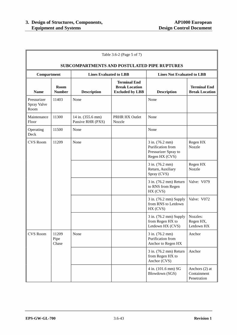
3. Design of Structures, Components, AP1000 European Equipment and Systems Design Control Document
EPS-GW-GL-700 3.6-43 Revision 1
Table 3.6-2 (Page 5 of 7)
SUBCOMPARTMENTS AND POSTULATED PIPE RUPTURES
Compartment Lines Evaluated to LBB Lines Not Evaluated to LBB
Name Room
Number Description
Terminal End Break Location
Excluded by LBB Description Terminal End
Break Location
Pressurizer Spray Valve Room
11403 None None
Maintenance Floor
11300 14 in. (355.6 mm) Passive RHR (PXS)
PRHR HX Outlet Nozzle
None
Operating Deck
11500 None None
CVS Room 11209 None 3 in. (76.2 mm) Purification from Pressurizer Spray to Regen HX (CVS)
Regen HX Nozzle
3 in. (76.2 mm) Return, Auxiliary Spray (CVS)
Regen HX Nozzle
3 in. (76.2 mm) Return to RNS from Regen HX (CVS)
Valve: V079
3 in. (76.2 mm) Supply from RNS to Letdown HX (CVS)
Valve: V072
3 in. (76.2 mm) Supply from Regen HX to Letdown HX (CVS)
Nozzles: Regen HX, Letdown HX
CVS Room None 3 in. (76.2 mm) Purification from Anchor to Regen HX
Anchor
3 in. (76.2 mm) Return from Regen HX to Anchor (CVS)
Anchor
11209 Pipe Chase
4 in. (101.6 mm) SG Blowdown (SGS)
Anchors (2) at Containment Penetration
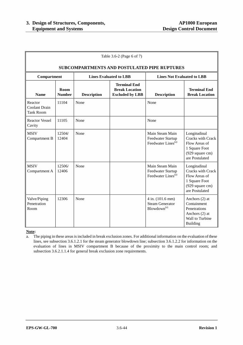
3. Design of Structures, Components, AP1000 European Equipment and Systems Design Control Document
EPS-GW-GL-700 3.6-44 Revision 1
Table 3.6-2 (Page 6 of 7)
SUBCOMPARTMENTS AND POSTULATED PIPE RUPTURES
Compartment Lines Evaluated to LBB Lines Not Evaluated to LBB
Name Room
Number Description
Terminal End Break Location
Excluded by LBB Description Terminal End
Break Location
Reactor Coolant Drain Tank Room
11104 None None
Reactor Vessel Cavity
11105 None None
MSIV Compartment B
12504/ 12404
None Main Steam Main Feedwater Startup Feedwater Lines(a)
Longitudinal Cracks with Crack Flow Areas of 1 Square Foot (929 square cm) are Postulated
MSIV Compartment A
12506/ 12406
None Main Steam Main Feedwater Startup Feedwater Lines(a)
Longitudinal Cracks with Crack Flow Areas of 1 Square Foot (929 square cm) are Postulated
Valve/Piping Penetration Room
12306 None 4 in. (101.6 mm) Steam Generator Blowdown(a)
Anchors (2) at Containment Penetrations Anchors (2) at Wall to Turbine Building
Note: a. The piping in these areas is included in break exclusion zones. For additional information on the evaluation of these
lines, see subsection 3.6.1.2.1 for the steam generator blowdown line; subsection 3.6.1.2.2 for information on the evaluation of lines in MSIV compartment B because of the proximity to the main control room; and subsection 3.6.2.1.1.4 for general break exclusion zone requirements.
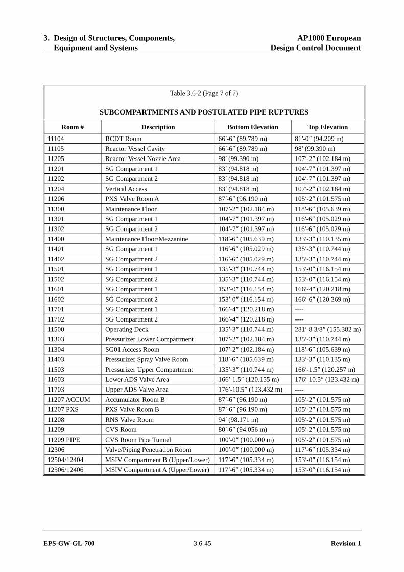
3. Design of Structures, Components, AP1000 European Equipment and Systems Design Control Document
EPS-GW-GL-700 3.6-45 Revision 1
Table 3.6-2 (Page 7 of 7)
SUBCOMPARTMENTS AND POSTULATED PIPE RUPTURES
Room # Description Bottom Elevation Top Elevation
11104 RCDT Room 66′-6″ (89.789 m) 81′-0″ (94.209 m)
11105 Reactor Vessel Cavity 66′-6″ (89.789 m) 98′ (99.390 m)
11205 Reactor Vessel Nozzle Area 98′ (99.390 m) 107′-2″ (102.184 m)
11201 SG Compartment 1 83′ (94.818 m) 104′-7″ (101.397 m)
11202 SG Compartment 2 83′ (94.818 m) 104′-7″ (101.397 m)
11204 Vertical Access 83′ (94.818 m) 107′-2″ (102.184 m)
11206 PXS Valve Room A 87′-6″ (96.190 m) 105′-2″ (101.575 m)
11300 Maintenance Floor 107′-2″ (102.184 m) 118′-6″ (105.639 m)
11301 SG Compartment 1 104′-7″ (101.397 m) 116′-6″ (105.029 m)
11302 SG Compartment 2 104′-7″ (101.397 m) 116′-6″ (105.029 m)
11400 Maintenance Floor/Mezzanine 118′-6″ (105.639 m) 133′-3″ (110.135 m)
11401 SG Compartment 1 116′-6″ (105.029 m) 135′-3″ (110.744 m)
11402 SG Compartment 2 116′-6″ (105.029 m) 135′-3″ (110.744 m)
11501 SG Compartment 1 135′-3″ (110.744 m) 153′-0″ (116.154 m)
11502 SG Compartment 2 135′-3″ (110.744 m) 153′-0″ (116.154 m)
11601 SG Compartment 1 153′-0″ (116.154 m) 166′-4″ (120.218 m)
11602 SG Compartment 2 153′-0″ (116.154 m) 166′-6″ (120.269 m)
11701 SG Compartment 1 166′-4″ (120.218 m) ----
11702 SG Compartment 2 166′-4″ (120.218 m) ----
11500 Operating Deck 135′-3″ (110.744 m) 281′-8 3/8″ (155.382 m)
11303 Pressurizer Lower Compartment 107′-2″ (102.184 m) 135′-3″ (110.744 m)
11304 SG01 Access Room 107′-2″ (102.184 m) 118′-6″ (105.639 m)
11403 Pressurizer Spray Valve Room 118′-6″ (105.639 m) 133′-3″ (110.135 m)
11503 Pressurizer Upper Compartment 135′-3″ (110.744 m) 166′-1.5″ (120.257 m)
11603 Lower ADS Valve Area 166′-1.5″ (120.155 m) 176′-10.5″ (123.432 m)
11703 Upper ADS Valve Area 176′-10.5″ (123.432 m) ----
11207 ACCUM Accumulator Room B 87′-6″ (96.190 m) 105′-2″ (101.575 m)
11207 PXS PXS Valve Room B 87′-6″ (96.190 m) 105′-2″ (101.575 m)
11208 RNS Valve Room 94′ (98.171 m) 105′-2″ (101.575 m)
11209 CVS Room 80′-6″ (94.056 m) 105′-2″ (101.575 m)
11209 PIPE CVS Room Pipe Tunnel 100′-0″ (100.000 m) 105′-2″ (101.575 m)
12306 Valve/Piping Penetration Room 100′-0″ (100.000 m) 117′-6″ (105.334 m)
12504/12404 MSIV Compartment B (Upper/Lower) 117′-6″ (105.334 m) 153′-0″ (116.154 m)
12506/12406 MSIV Compartment A (Upper/Lower) 117′-6″ (105.334 m) 153′-0″ (116.154 m)
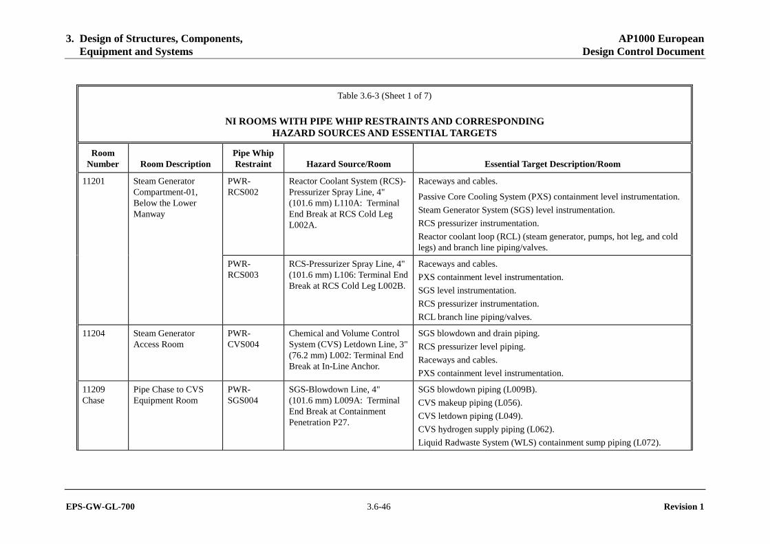
3. Design of Structures, Components, AP1000 European Equipment and Systems Design Control Document
EPS-GW-GL-700 3.6-46 Revision 1
Table 3.6-3 (Sheet 1 of 7)
NI ROOMS WITH PIPE WHIP RESTRAINTS AND CORRESPONDING HAZARD SOURCES AND ESSENTIAL TARGETS
Room Number Room Description
Pipe Whip Restraint Hazard Source/Room Essential Target Description/Room
PWR-RCS002
Reactor Coolant System (RCS)-Pressurizer Spray Line, 4" (101.6 mm) L110A: Terminal End Break at RCS Cold Leg L002A.
Raceways and cables.
Passive Core Cooling System (PXS) containment level instrumentation.
Steam Generator System (SGS) level instrumentation.
RCS pressurizer instrumentation.
Reactor coolant loop (RCL) (steam generator, pumps, hot leg, and cold legs) and branch line piping/valves.
11201 Steam Generator Compartment-01, Below the Lower Manway
PWR-RCS003
RCS-Pressurizer Spray Line, 4" (101.6 mm) L106: Terminal End Break at RCS Cold Leg L002B.
Raceways and cables.
PXS containment level instrumentation.
SGS level instrumentation.
RCS pressurizer instrumentation.
RCL branch line piping/valves.
11204 Steam Generator Access Room
PWR-CVS004
Chemical and Volume Control System (CVS) Letdown Line, 3" (76.2 mm) L002: Terminal End Break at In-Line Anchor.
SGS blowdown and drain piping.
RCS pressurizer level piping.
Raceways and cables.
PXS containment level instrumentation.
11209 Chase
Pipe Chase to CVS Equipment Room
PWR-SGS004
SGS-Blowdown Line, 4" (101.6 mm) L009A: Terminal End Break at Containment Penetration P27.
SGS blowdown piping (L009B).
CVS makeup piping (L056).
CVS letdown piping (L049).
CVS hydrogen supply piping (L062).
Liquid Radwaste System (WLS) containment sump piping (L072).
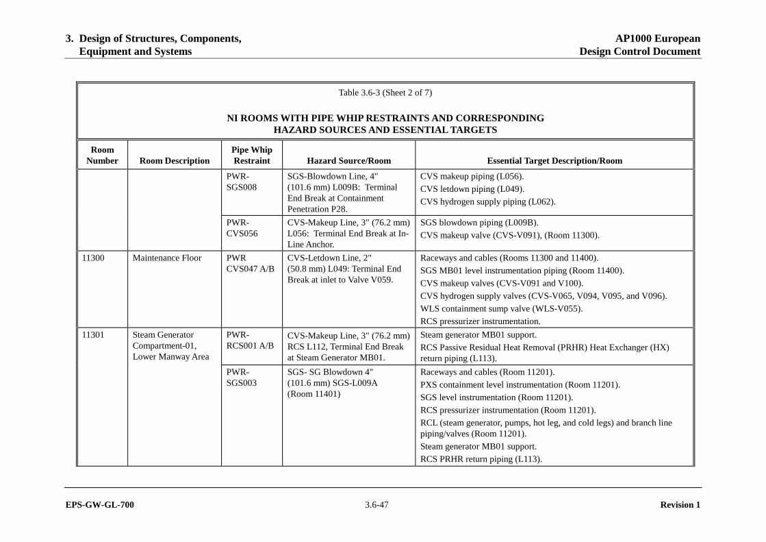
3. Design of Structures, Components, AP1000 European Equipment and Systems Design Control Document
EPS-GW-GL-700 3.6-47 Revision 1
Table 3.6-3 (Sheet 2 of 7)
NI ROOMS WITH PIPE WHIP RESTRAINTS AND CORRESPONDING HAZARD SOURCES AND ESSENTIAL TARGETS
Room Number Room Description
Pipe Whip Restraint Hazard Source/Room Essential Target Description/Room
PWR-SGS008
SGS-Blowdown Line, 4" (101.6 mm) L009B: Terminal End Break at Containment Penetration P28.
CVS makeup piping (L056).
CVS letdown piping (L049).
CVS hydrogen supply piping (L062).
PWR-CVS056
CVS-Makeup Line, 3" (76.2 mm) L056: Terminal End Break at In-Line Anchor.
SGS blowdown piping (L009B).
CVS makeup valve (CVS-V091), (Room 11300).
11300 Maintenance Floor PWR CVS047 A/B
CVS-Letdown Line, 2" (50.8 mm) L049: Terminal End Break at inlet to Valve V059.
Raceways and cables (Rooms 11300 and 11400).
SGS MB01 level instrumentation piping (Room 11400).
CVS makeup valves (CVS-V091 and V100).
CVS hydrogen supply valves (CVS-V065, V094, V095, and V096).
WLS containment sump valve (WLS-V055).
RCS pressurizer instrumentation.
PWR-RCS001 A/B
CVS-Makeup Line, 3" (76.2 mm) RCS L112, Terminal End Break at Steam Generator MB01.
Steam generator MB01 support.
RCS Passive Residual Heat Removal (PRHR) Heat Exchanger (HX) return piping (L113).
11301 Steam Generator Compartment-01, Lower Manway Area
PWR-SGS003
SGS- SG Blowdown 4" (101.6 mm) SGS-L009A (Room 11401)
Raceways and cables (Room 11201).
PXS containment level instrumentation (Room 11201).
SGS level instrumentation (Room 11201).
RCS pressurizer instrumentation (Room 11201).
RCL (steam generator, pumps, hot leg, and cold legs) and branch line piping/valves (Room 11201).
Steam generator MB01 support.
RCS PRHR return piping (L113).

3. Design of Structures, Components, AP1000 European Equipment and Systems Design Control Document
EPS-GW-GL-700 3.6-48 Revision 1
Table 3.6-3 (Sheet 3 of 7)
NI ROOMS WITH PIPE WHIP RESTRAINTS AND CORRESPONDING HAZARD SOURCES AND ESSENTIAL TARGETS
Room Number Room Description
Pipe Whip Restraint Hazard Source/Room Essential Target Description/Room
11302 Steam Generator Compartment-02, Lower Manway Area
PWR-SGS007
SGS- SG Blowdown 4” (101.6 mm) SGS-L009B (Room 11402).
SGS level instrumentation (Rooms 11202, 11302).
RCL and drain line piping/valves (Rooms 11202, 11302).
Steam generator MB02 support (Rooms 11202, 11302).
Raceways and cables (Rooms 11202, 11302).
PXS containment recirculation screen (Room 11202).
11400 Maintenance Floor Mezzanine
PWR-SGS002 A/B/C
SGS-Startup Feedwater Line, 6" (152.4 mm) L005A: Terminal End Break at Containment Penetration P44.
PXS PRHR HX ME01 upper head.
PXS PRHR HX ME01 upper head vent and drain piping and valves (PXS-V102A/B).
SGS MB01 level instrumentation piping.
Raceways and cables.
11402 Steam Generator Compartment-02, Tube Sheet Area
PWR-SGS006A/B
SGS-Startup Feedwater Line, 6" (152.4 mm) L005B: Terminal End Break at Containment Penetration P45 (Room 11400).
Steam generator MB02 and supports.
Primary Sampling System (PSS) core makeup tank (CMT) (MT02B) sample piping and valves (PSS V005B/C), (Room 11400).
PXS CMT MT02B vent piping and valve (PXS-V030B), (Room 11400).
PXS CMT MT02B balance line piping and valve (PXS-V002B), (Room 11400).
PXS CMT MT02B sample line piping and valve (PXS-V010B), (Room 11400).
PXS CMT MT02B makeup line piping (PXS-L012B), (Room 11400).
PXS CMT MT02B sample line piping (PXS-L011B), (Room 11400).
Raceways and cables, (Rooms 11400 and 11402).
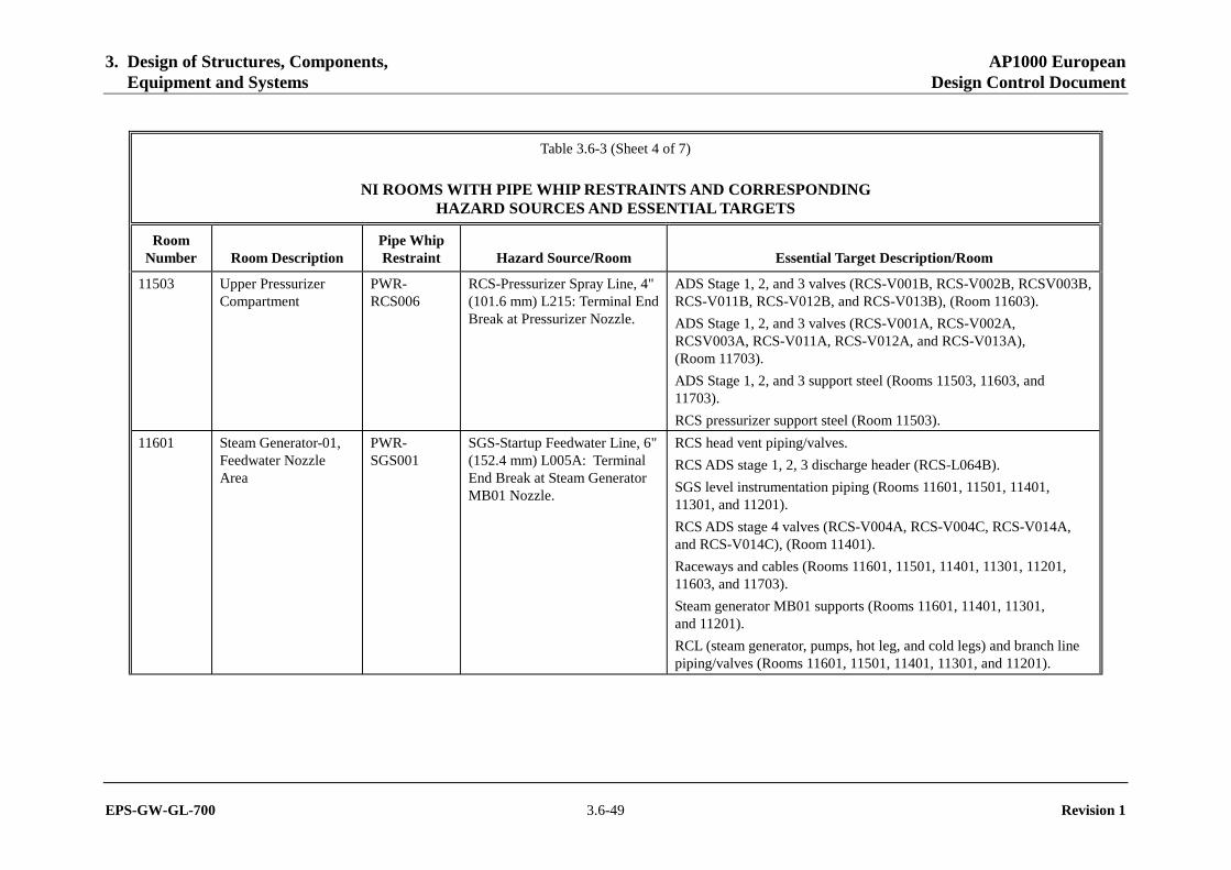
3. Design of Structures, Components, AP1000 European Equipment and Systems Design Control Document
EPS-GW-GL-700 3.6-49 Revision 1
Table 3.6-3 (Sheet 4 of 7)
NI ROOMS WITH PIPE WHIP RESTRAINTS AND CORRESPONDING HAZARD SOURCES AND ESSENTIAL TARGETS
Room Number Room Description
Pipe Whip Restraint Hazard Source/Room Essential Target Description/Room
11503 Upper Pressurizer Compartment
PWR-RCS006
RCS-Pressurizer Spray Line, 4" (101.6 mm) L215: Terminal End Break at Pressurizer Nozzle.
ADS Stage 1, 2, and 3 valves (RCS-V001B, RCS-V002B, RCSV003B, RCS-V011B, RCS-V012B, and RCS-V013B), (Room 11603).
ADS Stage 1, 2, and 3 valves (RCS-V001A, RCS-V002A, RCSV003A, RCS-V011A, RCS-V012A, and RCS-V013A), (Room 11703).
ADS Stage 1, 2, and 3 support steel (Rooms 11503, 11603, and 11703).
RCS pressurizer support steel (Room 11503).
11601 Steam Generator-01, Feedwater Nozzle Area
PWR-SGS001
SGS-Startup Feedwater Line, 6" (152.4 mm) L005A: Terminal End Break at Steam Generator MB01 Nozzle.
RCS head vent piping/valves.
RCS ADS stage 1, 2, 3 discharge header (RCS-L064B).
SGS level instrumentation piping (Rooms 11601, 11501, 11401, 11301, and 11201).
RCS ADS stage 4 valves (RCS-V004A, RCS-V004C, RCS-V014A, and RCS-V014C), (Room 11401).
Raceways and cables (Rooms 11601, 11501, 11401, 11301, 11201, 11603, and 11703).
Steam generator MB01 supports (Rooms 11601, 11401, 11301, and 11201).
RCL (steam generator, pumps, hot leg, and cold legs) and branch line piping/valves (Rooms 11601, 11501, 11401, 11301, and 11201).
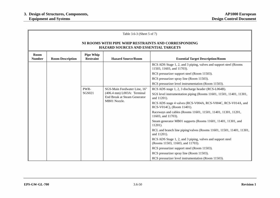
3. Design of Structures, Components, AP1000 European Equipment and Systems Design Control Document
EPS-GW-GL-700 3.6-50 Revision 1
Table 3.6-3 (Sheet 5 of 7)
NI ROOMS WITH PIPE WHIP RESTRAINTS AND CORRESPONDING HAZARD SOURCES AND ESSENTIAL TARGETS
Room Number Room Description
Pipe Whip Restraint Hazard Source/Room Essential Target Description/Room
RCS ADS Stage 1, 2, and 3 piping, valves and support steel (Rooms 11503, 11603, and 11703).
RCS pressurizer support steel (Room 11503).
RCS pressurizer spray line (Room 11503).
RCS pressurizer level instrumentation (Room 11503).
PWR-SGS021
SGS-Main Feedwater Line, 16" (406.4 mm) L003A: Terminal End Break at Steam Generator MB01 Nozzle.
RCS ADS stage 1, 2, 3 discharge header (RCS-L064B).
SGS level instrumentation piping (Rooms 11601, 11501, 11401, 11301, and 11201).
RCS ADS stage 4 valves (RCS-V004A, RCS-V004C, RCS-V014A, and RCS-V014C), (Room 11401).
Raceways and cables (Rooms 11601, 11501, 11401, 11301, 11201, 11603, and 11703).
Steam generator MB01 supports (Rooms 11601, 11401, 11301, and 11201).
RCL and branch line piping/valves (Rooms 11601, 11501, 11401, 11301, and 11201).
RCS ADS Stage 1, 2, and 3 piping, valves and support steel (Rooms 11503, 11603, and 11703).
RCS pressurizer support steel (Room 11503).
RCS pressurizer spray line (Room 11503).
RCS pressurizer level instrumentation (Room 11503).

3. Design of Structures, Components, AP1000 European Equipment and Systems Design Control Document
EPS-GW-GL-700 3.6-51 Revision 1
Table 3.6-3 (Sheet 6 of 7)
NI ROOMS WITH PIPE WHIP RESTRAINTS AND CORRESPONDING HAZARD SOURCES AND ESSENTIAL TARGETS
Room Number Room Description
Pipe Whip Restraint Hazard Source/Room Essential Target Description/Room
PWR-SGS005
SGS-Startup Feedwater Line, 6" (152.4 mm) L005B: Terminal End Break at Steam Generator MB02 Nozzle.
SGS level instrumentation piping (Rooms 11602, 11502, 11402, 11302, and 11202).
RCS ADS stage 4 valves (RCS-V004B, RCS-V004D, RCS-V014B, and RCS-V014D), (Room 11402).
Raceways and cables (Rooms 11602, 11502, 11402, 11302, 11202).
Steam generator MB02 supports (Rooms 11602, 11402, 11302, and 11202).
RCL and branch line piping/valves (Rooms 11602, 11502, 11402, 11302, and 11202).
PXS containment recirculation screen (Room 11202).
11602 Steam Generator-02, Feedwater Nozzle Area
PWR-SGS022
SGS-Main Feedwater line, 16" (406.4 mm) L003B: Terminal End Break at Steam Generator MB02 Nozzle.
SGS level instrumentation piping (Rooms 11602, 11502, 11402, 11302, and 11202).
RCS ADS stage 4 valves (RCS-V004B, RCS-V004D, RCS-V014B, and RCS-V014D), (Room 11402).
Raceways and cables (Rooms 11602, 11502, and 11402).
Steam generator MB02 supports (Rooms 11602, 11402, 11302, 11202).
RCL and branch line piping/valves (Rooms 11602, 11502, 11402, 11302, and 11202).
PXS containment recirculation screen (Room 11202).
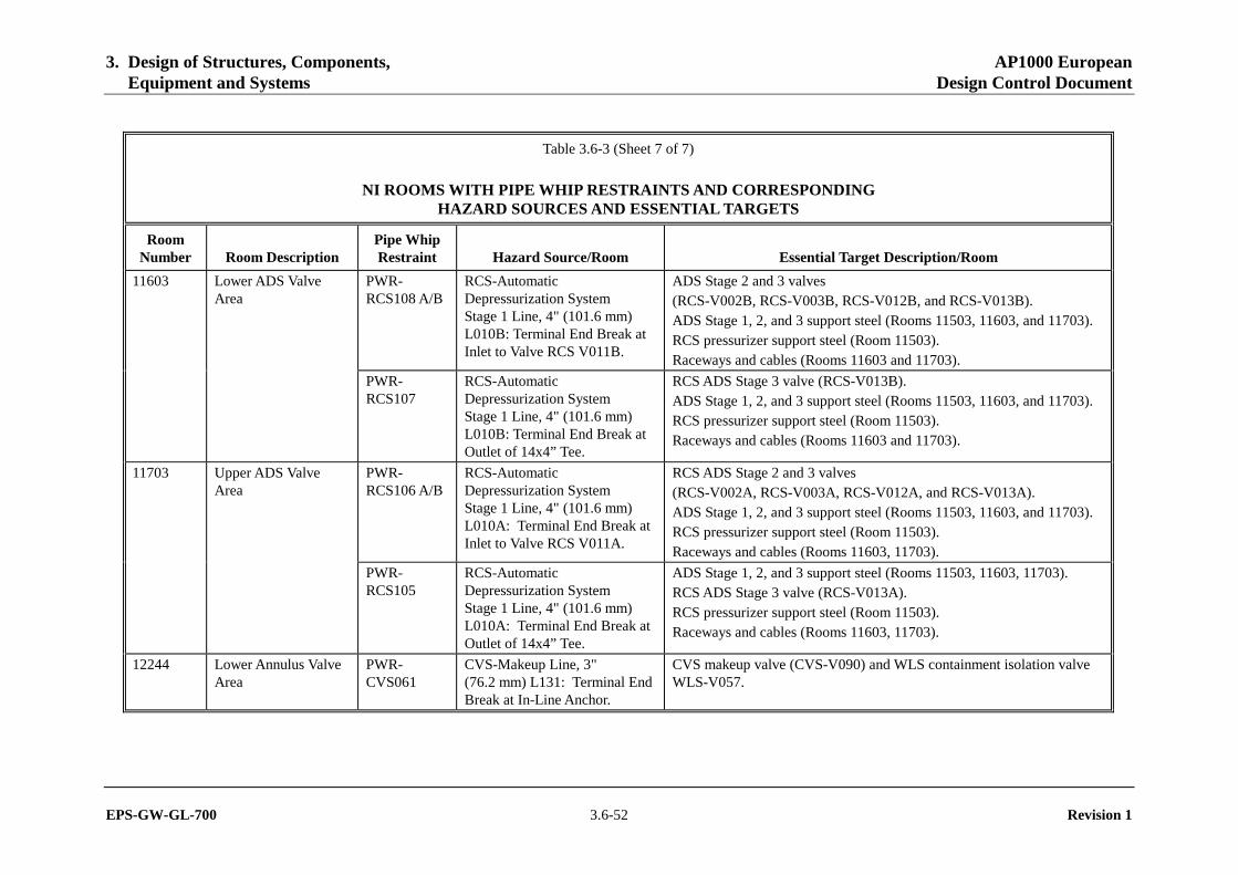
3. Design of Structures, Components, AP1000 European Equipment and Systems Design Control Document
EPS-GW-GL-700 3.6-52 Revision 1
Table 3.6-3 (Sheet 7 of 7)
NI ROOMS WITH PIPE WHIP RESTRAINTS AND CORRESPONDING HAZARD SOURCES AND ESSENTIAL TARGETS
Room Number Room Description
Pipe Whip Restraint Hazard Source/Room Essential Target Description/Room
PWR-RCS108 A/B
RCS-Automatic Depressurization System Stage 1 Line, 4" (101.6 mm) L010B: Terminal End Break at Inlet to Valve RCS V011B.
ADS Stage 2 and 3 valves (RCS-V002B, RCS-V003B, RCS-V012B, and RCS-V013B). ADS Stage 1, 2, and 3 support steel (Rooms 11503, 11603, and 11703). RCS pressurizer support steel (Room 11503). Raceways and cables (Rooms 11603 and 11703).
11603 Lower ADS Valve Area
PWR-RCS107
RCS-Automatic Depressurization System Stage 1 Line, 4" (101.6 mm) L010B: Terminal End Break at Outlet of 14x4” Tee.
RCS ADS Stage 3 valve (RCS-V013B). ADS Stage 1, 2, and 3 support steel (Rooms 11503, 11603, and 11703). RCS pressurizer support steel (Room 11503). Raceways and cables (Rooms 11603 and 11703).
PWR-RCS106 A/B
RCS-Automatic Depressurization System Stage 1 Line, 4" (101.6 mm) L010A: Terminal End Break at Inlet to Valve RCS V011A.
RCS ADS Stage 2 and 3 valves (RCS-V002A, RCS-V003A, RCS-V012A, and RCS-V013A). ADS Stage 1, 2, and 3 support steel (Rooms 11503, 11603, and 11703). RCS pressurizer support steel (Room 11503). Raceways and cables (Rooms 11603, 11703).
11703 Upper ADS Valve Area
PWR-RCS105
RCS-Automatic Depressurization System Stage 1 Line, 4" (101.6 mm) L010A: Terminal End Break at Outlet of 14x4” Tee.
ADS Stage 1, 2, and 3 support steel (Rooms 11503, 11603, 11703). RCS ADS Stage 3 valve (RCS-V013A). RCS pressurizer support steel (Room 11503). Raceways and cables (Rooms 11603, 11703).
12244 Lower Annulus Valve Area
PWR-CVS061
CVS-Makeup Line, 3" (76.2 mm) L131: Terminal End Break at In-Line Anchor.
CVS makeup valve (CVS-V090) and WLS containment isolation valve WLS-V057.
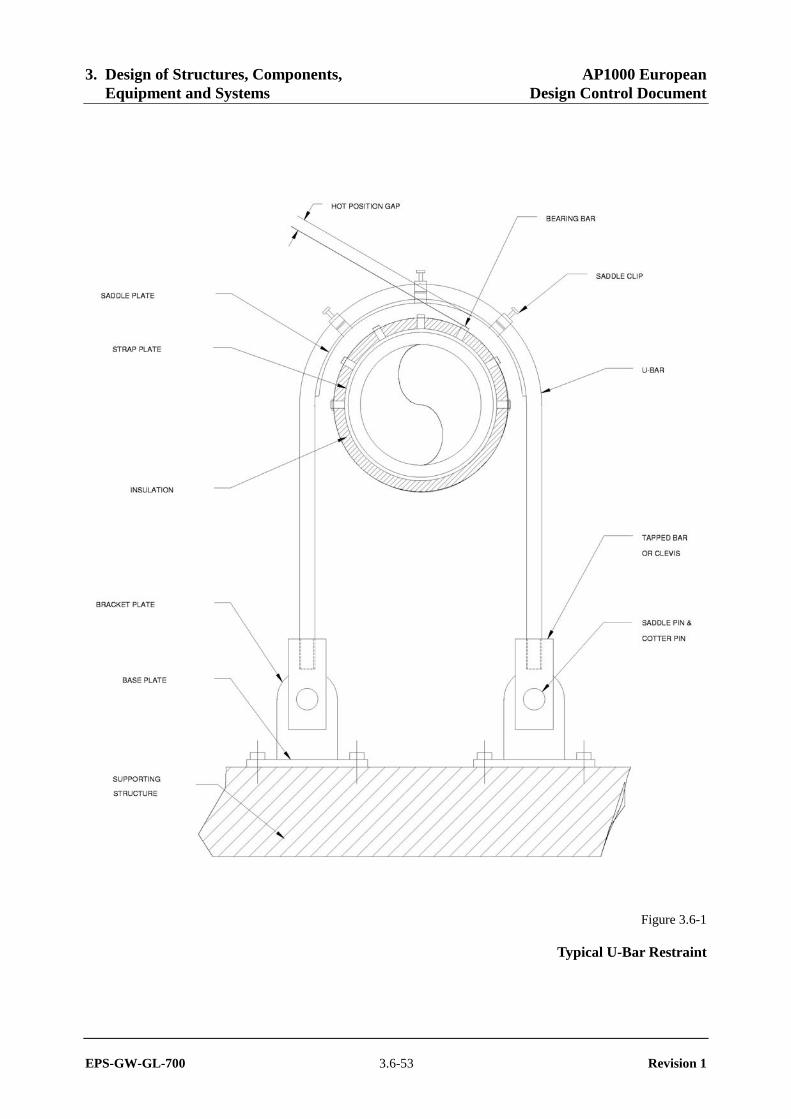
3. Design of Structures, Components, AP1000 European Equipment and Systems Design Control Document
EPS-GW-GL-700 3.6-53 Revision 1
Figure 3.6-1
Typical U-Bar Restraint
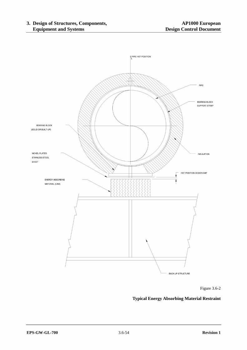
3. Design of Structures, Components, AP1000 European Equipment and Systems Design Control Document
EPS-GW-GL-700 3.6-54 Revision 1
Figure 3.6-2
Typical Energy Absorbing Material Restraint
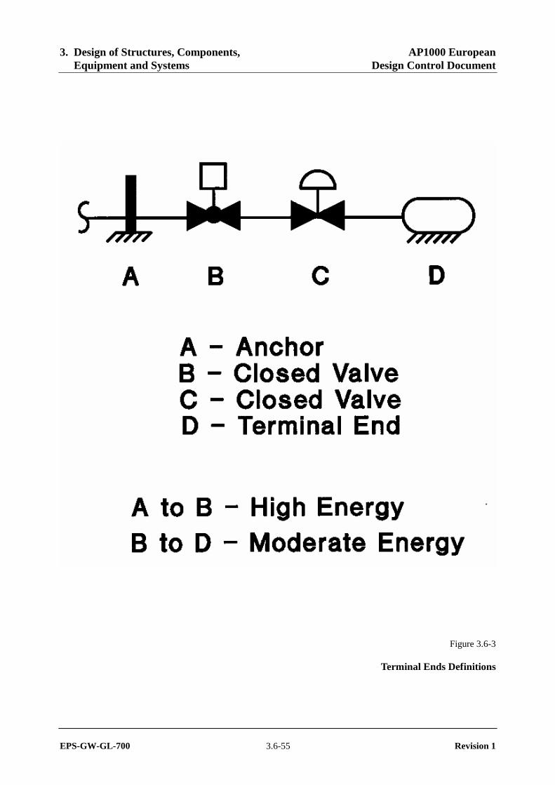
3. Design of Structures, Components, AP1000 European Equipment and Systems Design Control Document
EPS-GW-GL-700 3.6-55 Revision 1
Figure 3.6-3
Terminal Ends Definitions