Computer Controlled Steam Motor and Energy Conversion Unit ...

10. Steam and Power Conversion System AP1000 Design Control Document
Tier 2 Material 10.3-1 Revision 19
10.3 Main Steam Supply System
The main steam supply system as described in this section includes components of the AP1000 steam generator system (SGS), main steam system (MSS), and main turbine system (MTS).
The function of the main steam supply system is to supply steam from the steam generators to the high-pressure turbine over a range of flows and pressures covering the entire operating range from system warmup to maximum calculated turbine conditions.
The system provides steam to the moisture separator/reheaters and the gland seal system for the main turbine. The system dissipates heat generated by the nuclear steam supply system (NSSS) by means of steam dump valves to the condenser or to the atmosphere through power-operated atmospheric relief valves or spring-loaded main steam safety valves when either the turbine-generator or condenser is unavailable.
10.3.1 Design Basis
10.3.1.1 Safety Design Basis
The main steam supply system safety design bases are as follows:
• The system is provided with a main steam isolation valve (MSIV) and associated MSIV bypass valve on each main steam line from its respective steam generator. These valves isolate the secondary side of each of the steam generators to prevent the uncontrolled blowdown of more than one steam generator and isolate nonsafety-related portions of the system.
• Codes and standards utilized in the design of the main steam supply system are identified in Section 3.2, according to the AP1000 equipment class of the component. The main steam supply system contains class B and class C safety-related components.
Table 3.2-3 identifies the safety-related mechanical equipment in the main steam supply system, and lists the associated ASME code class. (Since all the safety-related components of the main steam supply system are in the AP1000 steam generator system [SGS], they appear in that table with an SGS prefix. For example, the main steam isolation valves [MSIVs] are listed there as SGS-PL-V040A and B).
The following main steam supply system components are classified as equipment class B and are safety-related:
– The main steam line piping from the steam generator up to, and including, the main steam isolation valves
– The main steam isolation valve bypass piping up to, and including, the main steam isolation bypass valve
– The inlet piping from the main steam line up to, and including, the main steam safety valves

10. Steam and Power Conversion System AP1000 Design Control Document
Tier 2 Material 10.3-2 Revision 19
– The inlet piping from the main steam line up to, and including, the power operated relief valve block valve
– The instrumentation piping up to, and including, the main steam line pressure instrument root valves
– The vent line on the main steam line up to, and including, the first isolation valve, and the nitrogen connection on the main steam line up to, and including, the first isolation valve
– The main steam drain condensate pot located upstream of the main steam isolation valves, and the drain piping up to, and including, the first isolation valve
The following main steam supply system components are classified as equipment class C and are safety-related:
– The main steam line piping from the main steam isolation valves outlet to the pipe restraint located on the wall between the auxiliary building and the turbine building
– The main steam safety valve discharge piping and vent stacks
– The piping from the outlet of the power operated relief block valve up to, and including, the power operated relief valve
– The condensate drain piping from the outlet of the class B isolation valve to the restraint on the wall between the auxiliary building and the turbine building
(The remainder of the main steam supply system is nonsafety-related. Except for the power operated relief valve discharge piping from the power operated relief valve outlet to the power operated relief valve silencer, which is class D, the remainder of the main steam supply system is class E).
• The system provides suitable overpressure protection of the steam generator secondary side and class 2 main steam piping in accordance with ASME Code, Section III.
• The safety-related portion of the system is designed to withstand the effects of a safe shutdown earthquake and to perform its intended function following postulated events.
• The safety-related portions of the system are protected from wind and tornado effects, as described in Section 3.3; flood protection is described in Section 3.4; missile protection is described in Section 3.5; protection against dynamic effects associated with the postulated rupture of piping is described in Section 3.6; seismic protection is described in Section 3.7; environmental design is described in Section 3.11; and fire protection is described in Section 9.5.

10. Steam and Power Conversion System AP1000 Design Control Document
Tier 2 Material 10.3-3 Revision 19
• The safety-related portion of the system is designed so that a single, active failure in the main steam supply system will not result in:
– A loss-of-coolant accident
– Loss of integrity of other steam lines
– Loss of the capability of the engineered safety features system to effect a safe reactor shutdown
– Transmission of excessive loading to the containment pressure boundary
Component or functional redundancy is provided so that safety functions can be performed assuming a single, active failure coincident with loss of offsite power. Consistent with NUREG 0138 and Standard Review Plan Section 10.3, the nonsafety-related valves downstream of the main steam isolation valves are assumed functional to effect this capability.
• The portion of the main steam supply system that is constructed in accordance with ASME Code, Section III, requirements is provided with access to welds and removable insulation, as required for in-service inspection in accordance with ASME Code, Section XI. (See subsection 10.3.4.4.)
• The main steam supply system is designed to function in the normal and accident environments identified in subsection 3.11.
• The main steam supply system is qualified to leak-before-break criteria as described in Section 3.6.
• The main steam supply system design complies with containment isolation criteria as discussed in subsection 6.2.3.
• The nonsafety-related turbine stop, turbine control, turbine bypass, and moisture separator reheater 2nd stage steam isolation valves are credited in a single failure analysis to mitigate the event for those cases in which the rupture of the main steam or feedwater piping inside containment is the postulated initiating event.
10.3.1.2 Power Generation Design Basis
The following is a list of the principal power generation design bases:
• The main steam supply system delivers steam from the steam generators to the turbine-generator for the range of flowrates, temperatures, and pressures existing from warmup to rated power conditions.
• Each main steam line is sized and routed to provide balanced steam pressures to the turbine stop valves.

10. Steam and Power Conversion System AP1000 Design Control Document
Tier 2 Material 10.3-4 Revision 19
• The main steam supply system provides the capacity to dump 40 percent of full plant load steam flow to the condenser during plant step-load reductions.
• The system provides the means of dissipating residual and sensible heat generated from the nuclear steam supply system during hot shutdown and cooldown even when the main condenser is not available. Power-operated atmospheric relief valves are provided to allow controlled cooldown of the steam generator and the reactor coolant system when the condenser is not available.
• Piping system components located downstream of the auxiliary building wall anchor assemblies are designed in accordance with the Power Piping Code, ANSI B31.1.
10.3.2 System Description
10.3.2.1 General Description
The main steam supply system shown in Figures 10.3.2-1 and 10.3.2-2 include the following major components:
• Main steam piping from the steam generator outlet steam nozzles to the main turbine stop valves
• One main steam isolation valve and one main steam isolation valve bypass valve per main steam line
• Main steam safety valves
• Power-operated atmospheric relief valves and upstream isolation valves
Table 10.3.2-1 lists the design data for the major components of the main steam supply system. Table 10.3.2-2 lists the design data for the main steam safety valve.
10.3.2.2 Component Description
10.3.2.2.1 Main Steam Piping
A description of the main steam piping from the steam generators to the turbine stop valves is presented in Table 10.3.2-3.
The main steam lines deliver a steamflow from the secondary side of the two steam generators. A portion of the main steamflow is directed to the reheater and steam seals, with the turbine receiving the remaining steamflow. Table 10.3.2-1 lists the performance data for the main steam supply system. Each of the main steam lines from the steam generators is anchored at the auxiliary building wall and has sufficient flexibility to accommodate thermal expansion.
Design of seismic Category I piping and supports takes into consideration the loads discussed in subsection 3.9.3.

10. Steam and Power Conversion System AP1000 Design Control Document
Tier 2 Material 10.3-5 Revision 19
The main steam lines between the steam generator and the containment penetration are designed to meet the leak-before-break criteria. The portion of the main steam lines between the containment penetration and the anchor downstream of the main steam isolation valves is part of the break exclusion zone. Section 3.6 addresses the applicability of leak-before-break and break exclusion zone to the main steam line.
The layout of the steam piping provides for the collection and drainage of condensate to avoid water entrainment, by the proper sloping of lines and the use of condensate drain pots.
The sizing and layout of the main steam piping hydraulically balances the steam line pressure drops from the respective steam generator to the inlet of each turbine stop valve. Two main steam lines are cross-connected into a common header just before branching into each turbine stop valve. This arrangement equalizes flow and pressure to the inlet of the turbine stop valves. This also permits online testing of each turbine stop valve without exceeding the allowable limit on steam generator pressure differential. Each steam generator outlet nozzle contains an internal flow restrictor arrangement to limit flow in the event of a main steam line break. A further description of the flow restrictor is provided in subsection 5.4.4.
Sampling connections are installed in the nonsafety-related portion of each main steam line, downstream of the main steam isolation valves. These nozzles are used for the sampling of steam. The sampling is monitored and analyzed through the secondary sampling system (SSS). Refer to subsection 9.3.4 for further discussion of the secondary sampling system.
Containment penetrations are described in subsection 6.2.3.
Turbine bypass valves are provided between the main steam isolation valves and turbine-generator stop valves, as discussed under the turbine bypass system (refer to subsection 10.4.4).
Main steam piping is designed to consider the effects of erosion/corrosion. Piping is constructed of erosion/corrosion resistant low alloy steel. Velocities in the main steam piping to the high pressure turbine are limited to reduce the potential for pipe erosion. Low point drains are provided for collecting and draining moisture and to help reduce the potential for water carryover to the high and low pressure turbines. Pipe wall thickness inspections are performed as required to monitor wall erosion rates.
Branch connections are provided from the main steam system to perform various functions. Upstream of the main steam isolation valves, there are connections for the power-operated atmospheric relief valves, main steam safety valves, low point drains, high point vents, and nitrogen blanketing. Branch piping downstream of the main steam line isolation valves includes connections for the two stage reheaters, turbine bypass system, auxiliary steam/gland seal system, and low point drains. Table 10.3.2-4 further describes branch piping, 2.5 inches and larger, that is downstream of the main steam isolation valves.

10. Steam and Power Conversion System AP1000 Design Control Document
Tier 2 Material 10.3-6 Revision 19
10.3.2.2.2 Main Steam Safety Valves
Main steam safety valves with sufficient rated capacity are provided to prevent the steam pressure from exceeding 110 percent of the main steam system design pressure:
• Following a turbine trip without a reactor trip and with main feedwater flow maintained • Following a turbine trip with a delayed reactor trip and with the loss of main feedwater flow
A total main steam safety valve rated capacity as indicated in Table 10.3.2-2 meets this requirement. At the same time, the individual safety valves are limited to the maximum allowable steam relief valve capacity as indicated in Table 10.3.2-2 for a system pressure equal to main steam design pressure plus 10 percent overpressure. This value sufficiently limits potential uncontrolled blowdown flow and the ensuing reactor transient should a single safety valve inadvertently fail or stick in the open position.
Six safety valves are provided per main steam line for the plant. Table 10.3.2-2 lists the performance data and set pressures for the main steam safety valves.
The main steam supply system safety valves are located in the safety-related portion of the main steam piping upstream of the main steam isolation valves and outside the containment in the auxiliary building. Adequate provision is made in the steam piping for the installation and support of the valves. Consideration is given to the static and dynamic loads when operating or when subjected to seismic events.
The piping and valve arrangement minimizes the loads on the attachment, and analysis confirms the design by use of guidelines in ASME Section III, Nonmandatory Appendix O, "Rules for Design of Safety Valve Installations."
Each safety valve is connected to vent stacks by an open umbrella-type transition piece schematically depicted in detail A of Figure 10.3.2-1.
The vent stacks are designed to:
• Direct the relieved steam away from adjoining structures
• Prevent backflow of relieved steam through the umbrella-type transition section
• Draw a small quantity of ambient air through the umbrella-type transition section and mix with the total steam flow which leaves the vent stack outlet
• Minimize the backpressure on the valve outlet so that it does not restrict the valve's rated capacity
The vent stacks are not required for safety, but are structurally designed to withstand safe-shutdown earthquake loads in order to not jeopardize the performance of safety-related components.

10. Steam and Power Conversion System AP1000 Design Control Document
Tier 2 Material 10.3-7 Revision 19
10.3.2.2.3 Power-Operated Atmospheric Relief Valves
A power-operated atmospheric relief valve is installed on the outlet piping from each steam generator to provide for controlled removal of reactor decay heat during normal reactor cooldown when the main steam isolation valves are closed or the turbine bypass system is not available. The valves are sized to provide a flow as indicated in Table 10.3.2-1. The maximum capacity of the relief valve at design pressure is limited to reduce the magnitude of a reactor transient if one valve would inadvertently open and remain open.
Each power-operated relief valve is located outside the containment in the auxiliary building upstream of the main steam isolation valves, in the safety-related portion of the main steam line associated with each steam generator. This location permits valve operation following transient conditions, including those which could result in closure of the main steam isolation valves.
The operation of the power-operated relief valves is automatically controlled by steam line pressure during plant operations. The power-operated relief valves automatically modulate open and exhaust to atmosphere whenever the steam line pressure exceeds a predetermined setpoint. As steam line pressure decreases, the relief valves modulate closed, reseating at a pressure at least 10 psi below the opening pressure. The setpoint is selected between no-load steam pressure and the set pressure of the lowest set safety valves.
The steam generator power-operated atmospheric relief valves provide a nonsafety-related means for plant cooldown by discharging steam to the atmosphere when the turbine bypass system is not available. Under such circumstances, the relief valves (in conjunction with the startup feedwater system) allow the plant to be cooled down at a controlled cooldown rate from the pressure setpoint of the lowest set of safety valves down to the point where the normal residual heat removal (RNS) system can remove the reactor heat.
For their use during plant cooldown, the power-operated atmospheric relief valves are automatically controlled by steam line pressure, with remote manual adjustment of the pressure setpoint from the control room or the remote shutdown workstation. To effect a plant cooldown, the operator manually adjusts the pressure setpoint downward in a step-wise fashion. The maximum cooldown rate achievable is limited by the flow-passing capability of the relief valves, the number of steam generators (and hence the number of relief valves) in service, the available startup feedwater pumping capacity and by the desire to either maintain or recover steam generator water levels during the cooldown.
The power-operated atmospheric relief valves also help to avoid actuation of the safety valves during certain transients and, following safety valve actuation, act to assist the safety valves to positively reseat by automatically reducing and regulating steam pressure to a value below the safety valve reseating pressure. The operation of each power-operated atmospheric relief valve is controlled in response to measurements of steam line pressure provided by four separate pressure taps on the associated steam line.
The valve operator is an air-operated modulating type, providing throttling capability over a range of steam pressures.

10. Steam and Power Conversion System AP1000 Design Control Document
Tier 2 Material 10.3-8 Revision 19
The atmospheric relief valves are controlled by nonsafety-related control systems for the modulating steam relief function. The capability for remote manual valve operation is provided in the main control room and at the remote shutdown workstation. A safety-related solenoid is provided to vent the air from the valve operator to terminate a steam line depressurization transient.
An isolation valve with remote controls is provided upstream of each power operated relief valve providing isolation of a leaking or stuck-open valve. The upstream location allows for maintenance on the power-operated relief valve operator at power. The motor-operated isolation valve employs a safety-related operator and closes automatically on low steam line pressure to terminate steam line depressurization transients. The isolation valve is a containment isolation boundary and therefore is specified as safety-related, active, ASME Code, Section III, Safety Class 2.
10.3.2.2.4 Main Steam Isolation Valves
The function of the main steam isolation is to limit blowdown to one steam generator in the event of a steam line break to:
• Limit the effect upon the reactor core to within specified fuel design limits • Limit containment pressure to a value less than design pressure
Main steam isolation consists of one quick-acting gate valve in each main steam line and one associated globe main steam isolation bypass valve with associated actuators and instrumentation. These valves are located outside the containment, downstream of the steam generator safety valves and the atmospheric relief valve, in the auxiliary building. The isolation valves provide positive shutoff with minimum leakage during postulated line severance conditions either upstream or downstream of the valves.
The main steam isolation valves close fully upon receipt of a manual or automatic signal and remain fully closed. Upon receipt of the closing signal, the main steam isolation valves complete the closing cycle despite loss of normally required utility services for actuator and/or instrumentation. On loss of actuating hydraulic power, the valves fail to the closed position. On loss of electrical power the valves remain in their current position. Position indication and remote manual operation of the isolation valves are provided in the control room and remote shutdown workstation. Additionally, provisions are made for in-service inspection of the isolation valves.
Closure of the main steam isolation valves and main steam isolation bypass valves is initiated by the following:
• Low steam line pressure in one of two loops
• High containment pressure
• High negative steam pressure rate in one of two loops
• Low Tcold in either reactor coolant loop

10. Steam and Power Conversion System AP1000 Design Control Document
Tier 2 Material 10.3-9 Revision 19
• Manual actuation: There are four controls for main steam line actuation. Two of the controls provide system level actuation, that is, isolate both steam lines, and two of the controls, one per loop, provide isolation of a single steam line.
• Manual reset: In addition to the controls for manual isolation actuation, there are two controls for manual reset of the steam line isolation signal, one for each of the logic divisions associated with steam line controls, which can be used to manually reset that division’s steam line isolation signal.
Each main steam isolation valve is a bidirectional wedge type gate valve composed of a valve body that is welded into the system pipeline. The main steam isolation gate valve is provided with a hydraulic/pneumatic actuator. The valve actuator is supported by the yoke, which is attached to the top of the body. The valve actuator consists of a hydraulic cylinder with a stored energy system to provide emergency closure of the isolation valve. The energy to operate the valve is stored in the form of compressed nitrogen contained in one end of the actuator cylinder. The main steam isolation valve is maintained in a normally open position by high-pressure hydraulic fluid. For emergency closure, redundant solenoids are energized resulting in the high-pressure hydraulic fluid being dumped to a fluid reservoir.
The main steam isolation bypass valves are used to permit warming of the main steam lines prior to startup when the main steam isolation valves are closed. The bypass valves are modulating, air-operated globe valves. For emergency closure, redundant 1E solenoids are provided. Each solenoid is energized from a separate safety-related division.
10.3.2.3 System Operation
10.3.2.3.1 Normal Operation
During normal power operation, the main steam supply system supplies steam to meet the demand of the main turbine system. The main steam supply system also supplies steam as required to the auxiliary steam system, and reheating steam to the moisture separator reheater. The main steam supply system also provides steam to the turbine gland seal system.
The main steam supply system is capable of accepting a ±10-percent step change in load followed by a ±5-percent/min ramp change without discharging steam to the atmosphere through the main steam safety valves or to the main condenser through the turbine bypass system. For large step change load reductions, steam is bypassed (up to 40 percent of full load flow) directly to the condenser via the turbine bypass system. As discussed in subsection 10.4.4, the main steam supply system, in conjunction with the turbine bypass system, is capable of accepting a 100-percent net load rejection without reactor trip (in conjunction with a reactor rapid power reduction) and without lifting safety valves. If the turbine bypass system is not available, steam is vented to the atmosphere via the power-operated atmospheric relief valves and the main steam safety valves, as required.

10. Steam and Power Conversion System AP1000 Design Control Document
Tier 2 Material 10.3-10 Revision 19
10.3.2.3.2 Emergency Operation
In the event that the plant must be shut down, the main steam isolation valves with associated main steam isolation bypass valves and other valves associated with the main steam lines can be closed. The power-operated atmospheric relief valves are then used to remove reactor decay and primary system sensible heat to cooldown to conditions at which the normal residual heat removal system can perform the remaining cooldown function. If the power-operated atmospheric relief valve for an individual main steam line is unavailable because of the loss of its control or power supply, the respective safety valves will provide overpressure protection. The remaining power-operated atmospheric relief valve is sufficient to cooldown the plant.
In the event that a design basis accident occurs, which results in a large steam line break, the main steam isolation valves with associated main steam isolation bypass valves automatically close. The closure of the main steam isolation valves and associated main steam isolation bypass valves result in no more than one steam generator supplying a postulated break.
The passive residual heat removal system (Section 6.3) provides safety-related decay heat removal capability should steam relief and feedwater be unavailable.
10.3.3 Safety Evaluation
• Each main steam line is provided with safety valves that limit the pressure in the line to limit over-pressurization and remove stored energy. Each line is provided with a power-operated atmospheric relief valve to permit reduction of the main steam line pressure and remove stored energy to achieve an orderly shutdown. The startup feedwater system, described in subsection 10.4.9, provides makeup to the steam generators consistent with the steaming rate.
• Redundant power supplies and power divisions operate the main steam isolation valves and main steam isolation bypass valves to isolate safety and nonsafety-related portions of the system. Branch lines upstream of the main steam isolation valves contain normally closed, power-operated atmospheric relief valves which modulate open and closed on steam line pressure. In the event the atmospheric relief valves fail closed, the safety valves provide overpressure protection.
Releases of radioactivity from the main steam system are minimized because there are no significant amounts of radioactivity in the system under normal operating conditions. Additionally, the main steam isolation system provides controls for reducing releases, as described in Chapter 15, following a steam generator tube rupture.
Detection of radioactive leakage into the system, which is characteristic of a steam generator tube leak or rupture, is facilitated by adjacent-to-line radiation monitors on each steam line, the radiation monitor in the turbine vent and drain system which monitors condenser air removal, and the steam generator blowdown line radiation monitor.
• Section 3.2 provides the quality group classification, the required design and fabrication codes, and seismic category applicable to the safety-related portion of this system and

10. Steam and Power Conversion System AP1000 Design Control Document
Tier 2 Material 10.3-11 Revision 19
supporting systems. The power supplies and controls necessary for safety-related functions of the main steam supply system are safety-related, as described in Chapters 7 and 8.
• The safety-related portion of the main steam supply system is located in the containment and auxiliary building. These buildings are designed to withstand the effects of earthquakes, tornadoes, hurricanes, floods, external missiles, and other appropriate natural phenomena. Sections 3.3, 3.4, 3.5, 3.7, and 3.8 describe the bases of the structural design of these buildings.
The safety-related portion of the main steam supply system is designed to remain functional after a safe shutdown earthquake. Sections 3.7 and 3.9 provide the design loading conditions that were considered. Sections 3.5, 3.6, and 9.5 describe the analyses to provide confidence that a safe shutdown, as outlined in Section 7.4, is achieved and maintained.
• As indicated by the failure mode and effects analysis in Table 10.3.3-1, no single failure coincident with loss of offsite power compromises the system safety functions.
• The main steam supply system is initially tested with the program given in Chapter 14. Periodic in-service functional testing is done in accordance with subsection 10.3.4.
Section 6.6 provides the ASME Code, Section XI requirements that are appropriate for the safety-related portions of the main steam supply system.
• The safety-related components of the main steam supply system are qualified to function in normal, test, and accident environmental conditions. The environmental qualification program is described in Section 3.11.
• A discussion of high energy pipe break locations and evaluation of effects are provided in subsections 3.6.1 and 3.6.2.
• A discussion of the leak-before-break application and criteria is presented in subsection 3.6.3.
10.3.4 Inspection and Testing Requirements
10.3.4.1 Preoperational Testing
10.3.4.1.1 Valve Testing and Inspection
The operability and relief setpoints of the main steam safety valves will be verified at operating temperature using steam as the pressurization fluid. The advantage of this approach is that the testing at temperature will reduce the probability of having to adjust the valve setpoints during hot functional testing heatup. The valves may be either bench tested or in-situ tested. The valves will be adjusted to lift at their set pressure defined in Table 10.3.2-2.
The sum of the rated capacities of the valves shall exceed the capacity specified in Table 10.3.2-1. The relieving capacity of the valve is certified in accordance with the ASME Code, Section III NC-7000.

10. Steam and Power Conversion System AP1000 Design Control Document
Tier 2 Material 10.3-12 Revision 19
The lift-point of each power-operated atmospheric relief valve is checked against pressure gauges mounted in the main steam piping.
The power operated relief valves will be verified to have a relief capacity of at least 300,000 lbs/hour at 1106 psia in order to satisfy their non-safety related function of decay heat removal.
The main steam isolation valves are tested to verify the closing time prior to initial startup.
10.3.4.1.2 System Testing
The main steam supply system is designed to allow testing of system operation for both normal and emergency operating modes. This includes operation of applicable portions of the protection system.
The safety-related components of the system are designed and located to permit pre-service and in-service inspections.
10.3.4.1.3 Pipe Testing
The main steam lines within the containment and the auxiliary building are visually and volumetrically inspected at installation as required by ASME Code, Section XI pre-service inspection requirements.
10.3.4.2 In-service Testing
The performance and structural leaktight integrity of system components are demonstrated by operation.
Additional description of in-service inspection and in-service testing of ASME Code, Section III, Class 2 and 3 components is contained in Section 6.6 and subsection 3.9.6. The nonsafety-related turbine stop, turbine control, and moisture separator reheater 2nd stage steam isolation valves are included in the inservice test program discussed in subsection 3.9.6.
10.3.5 Water Chemistry
The objectives of the secondary side water chemistry program are as follows:
• Minimizing general corrosion in the steam generators, turbine, and feedwater system by maintaining proper pH control and by minimizing oxygen ingress (coupled with oxygen scavenging)
• Minimizing localized corrosion in the steam generators, turbine, and feedwater system by minimizing chemical contaminant ingress and by controlling contaminant levels through condensate polishing and steam generator blowdown.

10. Steam and Power Conversion System AP1000 Design Control Document
Tier 2 Material 10.3-13 Revision 19
10.3.5.1 Chemistry Control Basis
Steam Generator Owner’s Group recommendations are considered in the secondary side water chemistry program.
Secondary side water chemistry control basis for AP1000 is shown below:
System Design
• Selection of secondary side materials to minimize corrosive species such as copper oxides
• Capability of deaeration in the demineralized water supply path, condenser, and deaerator
• Capability of continuous blowdown of the steam generator bulk water
• Capability of post-construction cleaning of the feedwater system followed by wet layup of the feedwater system and steam generators
Operation Phase
• Early identification of contaminant ingress (salts, corrosion products, and oxygen)
• Capability to filter and demineralize condensate by passage of part of the condensate flow through a condensate polisher system prior to and during plant startup and shutdown and during power operation with abnormal secondary cycle chemistry.
• Chemical addition to establish and maintain an environment that minimizes system corrosion
• Identification of action levels based on chemistry conditions, as determined by high sensitivity continuous monitoring or by grab sampling
10.3.5.2 Contaminant Ingress
Contaminants may be introduced into the secondary side water system through three major mechanisms: makeup water; condenser tube leaks; atmospheric leaks at the condenser or pump seals. The following methods are used to detect the ingress of contaminants in the secondary water system:
• Demineralized water is continuously monitored as it is being produced in the water treatment plant.
• Ionic contaminants are detected by monitoring (either continuous process monitors or sample analysis) the condensate pump discharge, feedwater downstream of addition of heater and moisture separator drains, and steam generator bulk flow as blowdown.
• Atmospheric ingress is detected by monitoring the condensate pump discharge for excessive dissolved oxygen and by monitoring condenser air removal rate.

10. Steam and Power Conversion System AP1000 Design Control Document
Tier 2 Material 10.3-14 Revision 19
10.3.5.3 Condensate Polishing
A condensate polishing system with a capacity of one third design condensate flow is provided to remove corrosion products and ionic contaminants. This polishing system will not normally be employed during all phases of plant operation.
The secondary side water system has provisions for recirculating feedwater to the condenser prior to and during startup. The polisher may be used during this phase to remove corrosion products from the feedwater and thus prevent their ingress into the steam generators. Full flow or near full flow condensate polishing is possible at the lower condensate flows that exist during startup and low-power operation. See subsection 10.4.6 for additional information.
10.3.5.4 Chemical Addition
AP1000 employs an all-volatile treatment (AVT) method to minimize general corrosion in the feedwater system, steam generators, and main steam piping. A pH adjustment chemical and an oxygen scavenger are the two chemicals to be injected into the condensate pump discharge header, downstream of the condensate polishers.
To reduce the general corrosion rate of ferrous alloys, a volatile pH adjustment chemical is injected to maintain a noncorrosive environment. Although the pH adjustment chemical is volatile and will not concentrate in the steam generator, it will reach an equilibrium level which will help establish noncorrosive conditions.
An oxygen scavenger is added to maintain the dissolved oxygen content in the feedwater within specified limits for each mode of operation. The oxygen scavenger also promotes the formation of a protective magnetite layer on ferrous surfaces and keeps this layer in a reduced state, further inhibiting general corrosion.
10.3.5.5 Action Levels for Abnormal Conditions
Appropriate responses to abnormal chemistry conditions provide for the long-term integrity of secondary cycle components. Action taken when chemistry parameters are outside normal operating ranges will, in general, be consistent with action levels described in Reference 1.
Secondary side water chemistry guidelines are provided in Table 10.3.5-1.
10.3.5.6 Layup and Heatup
AP1000 anticipates no long-term steam generator layup under dry conditions. When maintenance or inspection is required on the secondary side of the steam generators, the steam generators are drained hot under nitrogen atmosphere. After cooling, the nitrogen purge is lifted and the maintenance/inspection begun.
Wet layup conditions are established for corrosion protection during outages. Guidelines are given in Table 10.3.5-2.

10. Steam and Power Conversion System AP1000 Design Control Document
Tier 2 Material 10.3-15 Revision 19
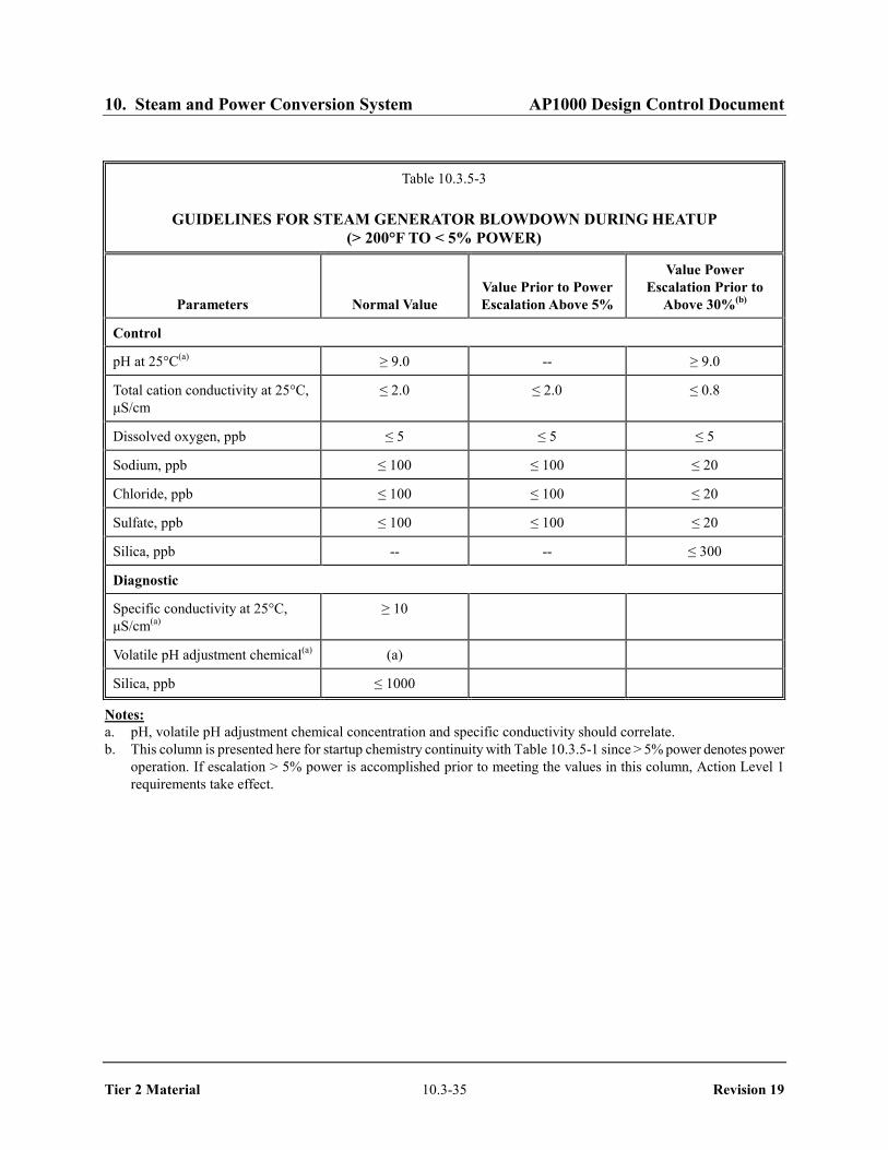
Before heatup to full power, the bulk water in the steam generators is normally brought into power operation specifications by draining and refilling or by feeding and bleeding. Guidelines for heatup are provided in Table 10.3.5-3.
10.3.5.7 Chemical Analysis Basis
Guidelines for chemical control and diagnostic parameters are listed in Table 10.3.5-1. Each parameter will be addressed as indicated below.
Oxygen in the presence of moisture rapidly corrodes carbon steel. These corrosion products may be carried through the feedwater system and form sludge in the steam generator. This sludge forms an environment for localized corrosion mechanisms on steam generator tubes. Thus, concentrations of oxygen are kept as low as practical in the feedwater system, and dissolved oxygen is controlled at the condenser and deaerator to prevent oxygen transport to the feedwater system.
Residual concentration of the oxygen scavenger is also measured in the feedwater sample and is used as input for injection of the oxygen scavenger.
In the absence of significant impurities, the pH is controlled by the concentration of the volatile pH adjustment chemical and the oxygen scavenger. Maintaining the pH within the recommended band results in minimal corrosion rates of ferrous materials.
Conductivity is also a measure of the presence of ionic contamination and provision is made for monitoring conductivity in samples of condensate, feedwater, and steam generator blowdown. Provision is also made for specific ions, such as sodium and chloride, which could be indicative of aggressive chemistry conditions.
10.3.5.8 Sampling
In addition to the sampling locations listed in Table 10.3.5-1, other sampling points are provided in the secondary side water system. These sampling points are identified in Table 9.3.4-1 (continuous sample points) and Table 9.3.4-2 (grab sample points).
10.3.5.9 Condenser Inspection
The secondary side water chemistry program includes an inspection program of the condenser to verify condenser integrity. This program includes a visual inspection of the condenser during outages and component inspection for air leaks during plant operation.
10.3.5.10 Conformance to Branch Technical Position MTEB 5-3
AP1000 conformance to Branch Technical Position MTEB 5-3 is discussed in Section 1.9.

10. Steam and Power Conversion System AP1000 Design Control Document
Tier 2 Material 10.3-16 Revision 19
10.3.6 Steam and Feedwater System Materials
10.3.6.1 Fracture Toughness
The material specifications for pressure-retaining materials in safety-related portions of the main steam and feedwater systems meet the fracture toughness requirements of ASME Code, Section III, Articles NC-2300 and ND-2300 for Quality Group B and Quality Group C components.
10.3.6.2 Material Selection and Fabrication
Pipe, flanges, fittings, valves, and other piping material conform to the referenced ASME, ASTM, ANSI, or Manufacturer Standardization Society-Standard Practice code.
No copper or copper-bearing materials are used in the steam and feedwater systems.
The following requirements apply to the nonsafety-related portion of the main steam system.
Component Alloy/Carbon Steel
Pipe ......................................................................................................... ANSI/ASME B36.10M Fittings ............................................................................................ANSI/ASME B16.9, B16.11 Flanges ......................................................................................................... ANSI/ASME B16.5
Material selection and fabrication requirements for ASME Code, Section III, Class 2 and 3 components in the safety-related portions of the main steam and feedwater systems are consistent with the requirements for ASME Class 2 and 3 systems and components outlined in subsections 6.1.1.1 and 6.1.1.2. Material specifications for the main steam and feedwater systems are listed in Table 10.3.2-3.
Conformance with the applicable regulatory guides is described in subsection 1.9.1.
Nondestructive inspection of ASME Code, Section III, Class 2 and 3 components in the safety-related portions of the main steam and feedwater systems is addressed in subsection 6.6.5.
10.3.7 Combined License Information
This section has no requirement for information to be provided in support of the Combined License application.
10.3.8 References
1. "PWR Secondary Water Chemistry Guidelines," EPRI TR-102134-R5, March 2000.

10. Steam and Power Conversion System AP1000 Design Control Document
Tier 2 Material 10.3-17 Revision 19
Table 10.3.2-1
MAIN STEAM SUPPLY SYSTEM DESIGN DATA
Steam Flow (lb/hr)
Maximum Calculated
Per steam generator 7.49x10⁶
Total 14.97x10⁶
Design Conditions
Design pressure (psia) 1200
Design temperature (°F) 600°F
Operating Conditions
Full plant load pressure (psia) 836
Full plant load temperature (°F) 523.3
No load (hot standby) pressure (psia) 1106
No load (hot standby) temperature (°F) 557
Main Steam Piping: See Table 10.3.2-3.
Steam Generator Flow Restrictor
Number per steam generator outlet nozzle 7
Throat size (ft2) 0.2
Total area (ft2) 1.4
Power-Operated Relief Valve
Number per main steam line 1
Normal set pressure 1138 psig
Design capacity
Minimum: 70,000 lb/hr at 100 psia steam generator pressure
Maximum: 1,020,000 lb/hr at 1200 psia steam generator pressure
Code ASME Code, Section III, Class 3, seismic Category I
Actuator Air-operated modulating

10. Steam and Power Conversion System AP1000 Design Control Document
Tier 2 Material 10.3-18 Revision 19
Table 10.3.2-2
DESIGN DATA FOR MAIN STEAM SAFETY VALVES
Number per main steam line 6
Total number of valves required per steam line for full power operation
6
Relieving capacity per valve at 110% of design pressure 1,370,000 lb/hr
Relieving capacity per steam line at 110% of design pressure 8,240,000 lb/hr
Total relieving capacity, 2 lines at 110% of design pressure 16,480,000 lb/hr
Valve size 8 x 10 (Dual Discharge)
Design code ASME Code, Section III, Class 2, seismic Category I
Valve Number Set Pressure
(psig) Relieving Capacity(a)
(lb/hr)
SGS PL V030A(B) 1185 ≥ 1,320,000
SGS PL V031A(B) 1197 ≥ 1,340,000
SGS PL V032A(B) 1209 ≥ 1,350,000
SGS PL V033A(B) 1221 ≥ 1,360,000
SGS PL V034A(B) 1232 ≥ 1,370,000
SGS PL V035A(B) 1232 ≥ 1,370,000
Total capacity, at 103% valve setpoint pressures, 2 lines ≥ 16,220,000
a. Based on system accumulation pressure of 3%, per Subsection NC-7512 of ASME Code, Section III, Division 1, 1989 Edition, Subsection NC, Class 2 components.
Note:

10. Steam and Power Conversion System AP1000 Design Control Document
Tier 2 Material 10.3-19 Revision 19
Table 10.3.2-3
DESCRIPTION OF MAIN STEAM AND MAIN FEEDWATER PIPING
Segment Material Specification
Main Steam Line
Steam generator outlet to containment penetration SA-335 Gr. P11 seamless pipe
Containment penetration to MSIV SA-335 Gr. P11 seamless pipe
MSIV to auxiliary/turbine building wall SA-335 Gr. P11 seamless pipe
Auxiliary/turbine building wall to equalization header(a) ASTM A-335 Gr. P11 seamless pipe
Branch lines to turbine stop valves(a) ASTM A-335 Gr. P11 seamless pipe
Main Feedwater Line
Feedwater pump outlet to individual steam generator feedwater lines(a)
ASTM A-335 Gr. P-11 and ASTM A-106 Gr. B
Feedwater heater bypass line(a) ASTM A-335 Gr. P-11 and ASTM A-106 Gr. B
Start of individual steam generator feedwater lines to auxiliary/turbine building wall(a)
ASTM A-335 Gr. P-11
Auxiliary/turbine building wall to MFIV SA-335 Gr. P-11
MFIV to containment penetration SA-335 Gr. P-11
Containment penetration to steam generator nozzle SA-335 Gr. P-11
a. Piping is beyond the ASME Section III piping boundary. Note:

10. Steam and Power Conversion System AP1000 Design Control Document
Tier 2 Material 10.3-20 Revision 19
Table 10.3.2-4
MAIN STEAM BRANCH PIPING (2.5-INCH AND LARGER) DOWNSTREAM OF MSIV
Description Maximum
Steam Flow Shutoff Valve
Valve Closure
Time Actuator Comments
Turbine bypass lines to condenser; 6 lines total
998,000 lb/hr each line
16-in. globe (turbine bypass valve)
5 sec or less(a)
when tripped closed
Air operator; fail close
Bypass valve is tripped closed on main steam isolation signal
Reheating steam to moisture separator reheater (MSR), 2 lines total
242,000 lb/hr, each MSR
10-in. globe (MSR reheat 2nd stage steam isolation valve, 2 each)
5 sec or less(a) Air operators, fail close
Main steam flow to reheater ceases (thermodynamically) following turbine trip flow ceases following valve closure on a main steam isolation signal
Main steam supply to auxiliary steam system
123,000 lb/hr 10-in. globe (isolation valve)
10 sec or less Air operator; fail close
Main steam flow to auxiliary steam system terminates following isolation valve closure on a main steam isolation signal
High pressure turbine steam supply lines; 4 lines total
3,744,000 lb/hr each line
27.5-in. stop valve in each line
5 sec or less(a) Hydraulically operated from electro-hydraulic turbine control system
Main steam flow to high pressure turbine ceases following stop valve closure on a turbine trip
Main steam supply to turbine glands
37,000 lb/hr 6-in. gate (isolation valve)
60 sec or less Motor operator; manually operated
Main steam flow to turbine seals continues following a turbine trip; however, this steam flow is relatively small and has been considered in the steam line break analysis (Section 3.6)
a. Specified closure times are for safety analysis purposes; other system performance requirements may dictate more rapid closure.
Note:

10. Steam and Power Conversion System AP1000 Design Control Document
Tier 2 Material 10.3-21 Revision 19
Table 10.3.3-1 (Sheet 1 of 10)
MAIN STEAM SUPPLY SYSTEM FAILURE MODES AND EFFECTS ANALYSIS
Item Description of
Component Safety Function
Plant Operating
Mode Failure Mode(s) Method of Failure
Detection
Failure Effect on System Safety Function
Capability General Remarks 1 MSIVs V040A(B)
normally open, fail closed with self contained hydraulic operator
Isolates SG A(B) in the event of a MSLB to prevent blowdown of more than one SG; Isolates containment in conjunction with SG and main steam line inside containment
a. All but DBA
a. Fails closed or fails to open on command
a. Position indication on main control room & remote shutdown work-station
a. None; Plant goes to or remains in a safe shutdown condition
One MSIV is provided for each steam line. Each MSIV redundantly activated from separate safety-related power divisions. Redundant backup provided by downstream isolation valves. Redundant containment isolation provided by SG and main steam line inside containment.
b. DBA Except SGTR
b. Fails to close upon ESF isolation signal
b. Position indica-tion on main control room & remote shutdown workstation
b. None; closure of either MSIV or downstream valves prevent blowdown of more than one SG; containment integrity is maintained by MSIV and either SG and steam line integrity inside containment or downstream valves.
c. DBA-SGTR
c. Fails to close on ESF isolation signal
c. Same as 1b c. None; limiting failure is PORV failed open discharging to atmo-sphere. Termination of break flow occurs on automatic block valve closure plus PRHR actuation. Continued break flow past MSIV precluded by redundant downstream isolation valves.
Redundant isolation provided by downstream isolation valves

10. Steam and Power Conversion System AP1000 Design Control Document
Tier 2 Material 10.3-22 Revision 19
Table 10.3.3-1 (Sheet 2 of 10)
MAIN STEAM SUPPLY SYSTEM FAILURE MODES AND EFFECTS ANALYSIS
Item Description of
Component Safety Function
Plant Operating
Mode Failure Mode(s) Method of Failure
Detection
Failure Effect on System Safety
Function Capability General Remarks
2 Main steam power operated relief valve V233A(B) normally closed fail closed, air- operated control valve
Isolates SG A(B) in the event of a MSLB to prevent blowdown from more than one SG in conjunction with block valve
a. All but DBA
a1. Fails to open upon open signal
a1. Position indica-tion on main control room & remote shutdown workstation; steam line high pressure
a1. None; heat removal available via steam dump or PRHR; safety valves provide over-pressure protection
Redundant isolation provided by PORV and block valve via separate safety-related power divisions.
a2. Fails open or fails to close on command including spurious operation
a2. Position indica- tion on main control room & remote shutdown workstation; low SG level or SG pressure
a2. None; maximum flow less than DBA limit; shutdown effected with 1 PORV, PRHR, or steam dump
b. DBA except SGTR
b. Fails to close
b. Position indica-tion on main control room & remote shutdown workstation; steam line low pressure alarm
b. None, redundant isolation provided by PORV block valve
Dose analysis based on failed open PORV with subsequent block valve closure
c. DBA - SGTR
c. Fail to close c. Position indica-tion on main control room & remote shutdown workstation; streamline low pressure alarm
c. None; automatic redundant isolation provided by PORV block valve. Releases based on signal generation and closure time delay

10. Steam and Power Conversion System AP1000 Design Control Document
Tier 2 Material 10.3-23 Revision 19
Table 10.3.3-1 (Sheet 3 of 10)
MAIN STEAM SUPPLY SYSTEM FAILURE MODES AND EFFECTS ANALYSIS
Item Description of
Component Safety Function
Plant Operating
Mode Failure Mode(s) Method of Failure
Detection
Failure Effect on System Safety
Function Capability General Remarks 3 Main steam line PORV
block valve V027A(B), normally open fail as is motor-operated gate valve
Isolates SG A(B) in the event of a MSLB to prevent blowdown from more than 1 SG in conjunction with PORV and provides containment integrity in conjunction with SG and main steam line inside containment
a. All but DBA
a1. Same as 2.a1 a2. Same as 2.a2
a1. Same as 2.a1 a2. Same as 2.a2
a1. Same as 2.a1 a2. Same as 2.a2
Redundant steam line isolation provided by PORV and block valve via separate safety-related power divisions. Redundant containment isolation provided by SG and main steam line inside containment.
b. DBA except SGTR
b. Same as 2b b. Position indication on main control room & remote shutdown workstation
b. Same as 2b; containment integrity is maintained by SG and main steam line inside containment
c. DBA SGTR c. Same as 2b c. Position indication on main control room & remote shutdown workstation
c. None, automatic redundant isolation of the PORV on low steam line pressure
Dose analysis based on failed open PORV isolated by block valve. Releases equivalent.
10. Steam and Power Conversion System AP1000 Design Control Document
Tier 2 Material 10.3-24 Revision 19
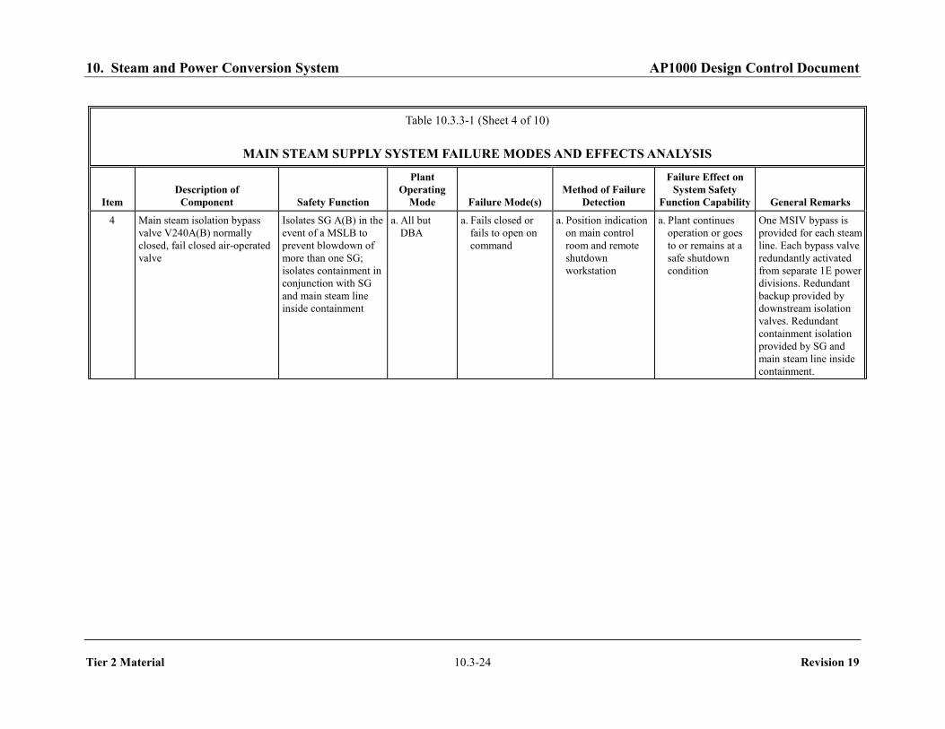
Table 10.3.3-1 (Sheet 4 of 10)
MAIN STEAM SUPPLY SYSTEM FAILURE MODES AND EFFECTS ANALYSIS
Item Description of
Component Safety Function
Plant Operating
Mode Failure Mode(s) Method of Failure
Detection
Failure Effect on System Safety
Function Capability General Remarks 4 Main steam isolation bypass
valve V240A(B) normally closed, fail closed air-operated valve
Isolates SG A(B) in the event of a MSLB to prevent blowdown of more than one SG; isolates containment in conjunction with SG and main steam line inside containment
a. All but DBA
a. Fails closed or fails to open on command
a. Position indication on main control room and remote shutdown workstation
a. Plant continues operation or goes to or remains at a safe shutdown condition
One MSIV bypass is provided for each steam line. Each bypass valve redundantly activated from separate 1E power divisions. Redundant backup provided by downstream isolation valves. Redundant containment isolation provided by SG and main steam line inside containment.

10. Steam and Power Conversion System AP1000 Design Control Document
Tier 2 Material 10.3-25 Revision 19
Table 10.3.3-1 (Sheet 5 of 10)
MAIN STEAM SUPPLY SYSTEM FAILURE MODES AND EFFECTS ANALYSIS
Item Description of
Component Safety Function Plant Operating
Mode Failure Mode(s) Method of Failure Detection
Failure Effect on System Safety
Function Capability General Remarks
b. DBA except SGTR
b. Fails to close upon ESF isolation signal
b. Position indication on main control room & remote shutdown workstation
b. None, closure of either bypass valve or down-stream isolation valves prevents blowdown of more than 1 SG; containment integrity maintained by either MSIV bypass valve or SG/steam line integrity inside containment
c. DBA-SGTR c. Fails to close on ESF isolation signal
c. Position indication on main control room & remote shutdown workstation
c. None, limiting failure is PORV failed open discharging to atmosphere. Termination of break flow occurs on automatic block valve closure plus passive RHR actuation. Continued break flow past MSIV bypass precluded by redundant downstream isolation valves
Redundant isolation provided by downstream isolation valves
10. Steam and Power Conversion System AP1000 Design Control Document
Tier 2 Material 10.3-26 Revision 19
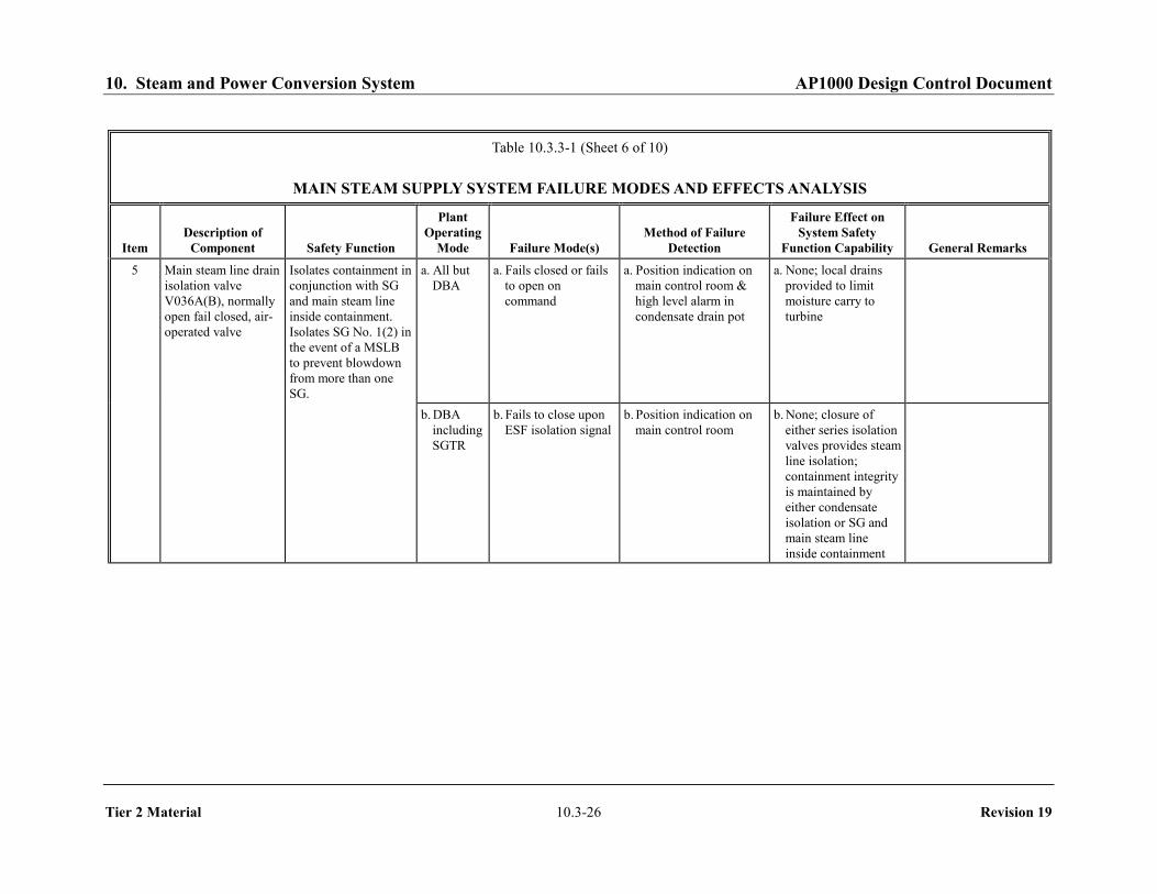
Table 10.3.3-1 (Sheet 6 of 10)
MAIN STEAM SUPPLY SYSTEM FAILURE MODES AND EFFECTS ANALYSIS
Item Description of
Component Safety Function
Plant Operating
Mode Failure Mode(s) Method of Failure
Detection
Failure Effect on System Safety
Function Capability General Remarks
5 Main steam line drain isolation valve V036A(B), normally open fail closed, air- operated valve
Isolates containment in conjunction with SG and main steam line inside containment. Isolates SG No. 1(2) in the event of a MSLB to prevent blowdown from more than one SG.
a. All but DBA
a. Fails closed or fails to open on command
a. Position indication on main control room & high level alarm in condensate drain pot
a. None; local drains provided to limit moisture carry to turbine
b. DBA including SGTR
b. Fails to close upon ESF isolation signal
b. Position indication on main control room
b. None; closure of either series isolation valves provides steam line isolation; containment integrity is maintained by either condensate isolation or SG and main steam line inside containment

10. Steam and Power Conversion System AP1000 Design Control Document
Tier 2 Material 10.3-27 Revision 19
Table 10.3.3-1 (Sheet 7 of 10)
MAIN STEAM SUPPLY SYSTEM FAILURE MODES AND EFFECTS ANALYSIS
Item Description of
Component Safety Function
Plant Operating
Mode Failure Mode(s) Method of Failure
Detection
Failure Effect on System Safety
Function Capability General Remarks 6 Main steam line drain control
valve V086A(B) normally closed, fail closed, air-operated valve
Isolates SG A(B) in the event of a main steam line break to prevent blowdown to more than one SG
a. All but DBA
a. Fails closed or fails to open on command
a. Position indication on main control room and high level alarm in condensate drain pot
a. None; local drains provided to limit moisture carryover to turbine
b. DBA including SGTR
b. Fails to close upon ESF isolation signal
b. Position indication provided on main control room
b. None, closure of either series isolation valves provides steam line isolation

10. Steam and Power Conversion System AP1000 Design Control Document
Tier 2 Material 10.3-28 Revision 19
Table 10.3.3-1 (Sheet 8 of 10)
MAIN STEAM SUPPLY SYSTEM FAILURE MODES AND EFFECTS ANALYSIS
Item Description of
Component Safety Function
Plant Operating
Mode Failure Mode(s) Method of Failure
Detection
Failure Effect on System Safety
Function Capability General Remarks 7 Main steam safety valves
V030A, V031A, V032A, V033A, V034A, V035A (V030B, V031B, V032B, V033B, V034B, V035B), normally closed
Protect SG A(B) and associated steam line up to MSIV from overpressurization
All a. Fails to open when required
a. Higher pressure and/or water level in SG A(B)
a. None, 5 out of 6 safety valves for SG A(B) still available with PORV available to supplement relief capacity; also, plant trip occurs on high steam generator level
b. Spurious opening or failure to reset after opening
b. Low steam line pressure
b. None, maximum flow from one safety valve less than DBA analysis assumptions, Shutdown effected by other SG or PRHR

10. Steam and Power Conversion System AP1000 Design Control Document
Tier 2 Material 10.3-29 Revision 19
Table 10.3.3-1 (Sheet 9 of 10)
MAIN STEAM SUPPLY SYSTEM FAILURE MODES AND EFFECTS ANALYSIS
Item Description of
Component Safety Function
Plant Operating
Mode Failure Mode(s) Method of
Failure Detection
Failure Effect on System Safety
Function Capability General Remarks 8 Steam Generator blowdown
isolation V074A(B), normally open, fail closed air-operated valve
Isolates blowdown from SG A(B) upon PRHR actuation; isolates containment in conjunction with SG and blowdown lines inside containment
All a. Fails closed or fails to open upon command
a. Position indication on the main control room and zero flow measured in blowdown system
a. None, blowdown is terminated but has no safety impact
b. Fails open or fails to close on command
b. Position indication on main control room
b. None, redundant isolation of blowdown via series isolation valve V075A(B), Containment integrity is maintained by blowdown isolation or SG and blowdown lines inside containment
Redundant isolation is provided for SG volume for PRHR operation via series valves; containment isolation via blowdown isolation or SG and blowdown lines inside containment

10. Steam and Power Conversion System AP1000 Design Control Document
Tier 2 Material 10.3-30 Revision 19
Table 10.3.3-1 (Sheet 10 of 10)
MAIN STEAM SUPPLY SYSTEM FAILURE MODES AND EFFECTS ANALYSIS
Item Description of
Component Safety Function
Plant Operating
Mode Failure Mode(s) Method of Failure
Detection
Failure Effect on System Safety
Function Capability General Remarks 9 Steam Generator blowdown
isolation V075A(B), normally open, fail closed air-operated valve
Isolates blowdown from SG A(B) upon PRHR actuation
All a. Fails closed or fails to open upon command
a. Position indication on main control room and zero flow in blowdown system
a. None, blowdown is terminated but has no safety impact
b. Fails open or fails to close on command
b. Position indication on main control room
b. None, redundant isolation of blowdown via series isolation valve V074A(B)
Redundant isolation is provided for SG volume for PRHR operation via series valves

10. Steam and Power Conversion System AP1000 Design Control Document
Tier 2 Material 10.3-31 Revision 19
Table 10.3.5-1 (Sheet 1 of 3)
GUIDELINES FOR SECONDARY SIDE WATER CHEMISTRY DURING POWER OPERATION
CONDENSATE
Parameters Normal Value
Control
Cation conductivity due to strong acid anions at 25°C, μS/cm ≤ 0.15
Total cation conductivity at 25°C, μS/cm ≤ 0.3
Dissolved oxygen, ppb(a) ≤ 10
Diagnostic
Total organic carbon, ppb ≤ 100
Sodium, ppb < 1
pH at 25°C > 9.0
Specific conductivity at 25°C, μS/cm 2 - 6
Volatile pH adjustment chemical, ppb (b)
a. Air leakage should be reduced until total air ejected flow rate is less than 6 scfm. Notes:
b. pH, volatile pH adjustment chemical concentration and specific conductivity should correlate.

10. Steam and Power Conversion System AP1000 Design Control Document
Tier 2 Material 10.3-32 Revision 19
Table 10.3.5-1 (Sheet 2 of 3)
GUIDELINES FOR SECONDARY SIDE WATER CHEMISTRY DURING POWER OPERATION
FEEDWATER
Parameters Normal Value
Control
pH at 25°C(a) > 9.5
Hydrazine, ppb(c) ≥ 100
Total iron, ppb ≤ 20
Diagnostic
Dissolved oxygen, ppb ≤ 2
Cation conductivity due to strong acid anions at 25°C, μS/cm ≤ 0.2
Specific conductivity at 25°C, μS/cm 4.0 - 12.0
Volatile pH adjustment chemical, ppb (a)
a. pH, volatile pH adjustment chemical concentration and specific conductivity should correlate. Notes:
b. When operating with condensate polishers, the pH of an all-ferrous system can be controlled to a lower value of 9.2, with action required when pH < 9.2.
c. Values apply if hydrazine is used for oxygen scavenging. An alternate oxygen scavenger may be used with appropriate concentration limits.

10. Steam and Power Conversion System AP1000 Design Control Document
Tier 2 Material 10.3-33 Revision 19
Table 10.3.5-1 (Sheet 3 of 3)
GUIDELINES FOR SECONDARY SIDE WATER CHEMISTRY DURING POWER OPERATION
STEAM GENERATOR BLOWDOWN
Parameters Normal Value
Control
pH at 25°C(a) 9.0 - 9.5(b)
Total cation conductivity ≤ 0.8(c)
Sodium, ppb ≤ 20
Chloride, ppb ≤ 20
Sulfate, ppb ≤ 20
Silica, ppb ≤ 300
Diagnostic
Cation conductivity due to strong acid anions at 25°C, μS/cm ≤ 0.5
Suspended solids, ppb < 1000
Specific conductivity at 25°C, μS/cm < 3.0
Volatile pH adjustment chemical, ppb (a)
a. pH, volatile pH adjustment chemical concentration and specific conductivity should correlate. Notes:
b. When operating with condensate polishers, the pH of an all-ferrous system can be controlled to a value of > 8.8. c. Based on concentrations of total anionic species present, any inconsistencies between theoretical and measured
values should be investigated.

10. Steam and Power Conversion System AP1000 Design Control Document
Tier 2 Material 10.3-34 Revision 19
Table 10.3.5-2
GUIDELINES FOR STEAM GENERATOR WATER DURING COLD SHUTDOWN/WET LAYUP
Parameters Normal Value Prior to Heatup
(≤ 200°F)
Control
pH at 25°C 9.8 - 10.5 ≥ 9.3(a)
Hydrazine, ppm(b) 75 - 200
Sodium, ppb ≤ 1000 ≤ 100
Chloride, ppb ≤ 1000 ≤ 100
Sulfate, ppb ≤ 1000 ≤ 100
Diagnostic
Volatile pH adjustment chemical - as required to achieve pH range
Total organic carbon, ppb ≤ 100
a. Conformance with pH guideline may be waived prior to achieving no load temperature and passing steam forward to turbine.
Notes:
b. Values apply if hydrazine is used for oxygen scavenging. An alternate oxygen scavenger may be used with appropriate concentration limits.
10. Steam and Power Conversion System AP1000 Design Control Document
Tier 2 Material 10.3-35 Revision 19
Table 10.3.5-3
GUIDELINES FOR STEAM GENERATOR BLOWDOWN DURING HEATUP (> 200°F TO < 5% POWER)
Parameters Normal Value Value Prior to Power Escalation Above 5%
Value Power Escalation Prior to
Above 30%(b)
Control
pH at 25°C(a) ≥ 9.0 -- ≥ 9.0
Total cation conductivity at 25°C, μS/cm
≤ 2.0 ≤ 2.0 ≤ 0.8
Dissolved oxygen, ppb ≤ 5 ≤ 5 ≤ 5
Sodium, ppb ≤ 100 ≤ 100 ≤ 20
Chloride, ppb ≤ 100 ≤ 100 ≤ 20
Sulfate, ppb ≤ 100 ≤ 100 ≤ 20
Silica, ppb -- -- ≤ 300
Diagnostic
Specific conductivity at 25°C, μS/cm(a)
≥ 10
Volatile pH adjustment chemical(a) (a)
Silica, ppb ≤ 1000
a. pH, volatile pH adjustment chemical concentration and specific conductivity should correlate. Notes:
b. This column is presented here for startup chemistry continuity with Table 10.3.5-1 since > 5% power denotes power operation. If escalation > 5% power is accomplished prior to meeting the values in this column, Action Level 1 requirements take effect.

10. Steam and Power Conversion System AP1000 Design Control Document
Tier 2 Material 10.3-36 Revision 19
[This page intentionally blank]

10. Steam and Power Conversion System AP1000 Design Control Document
Tier 2 Material 10.3-37 Revision 19
Figure 10.3.2-1 (Sheet 1 of 2)
Main Steam Piping and Instrumentation Diagram (Safety-Related System)
(REF) SGS 001
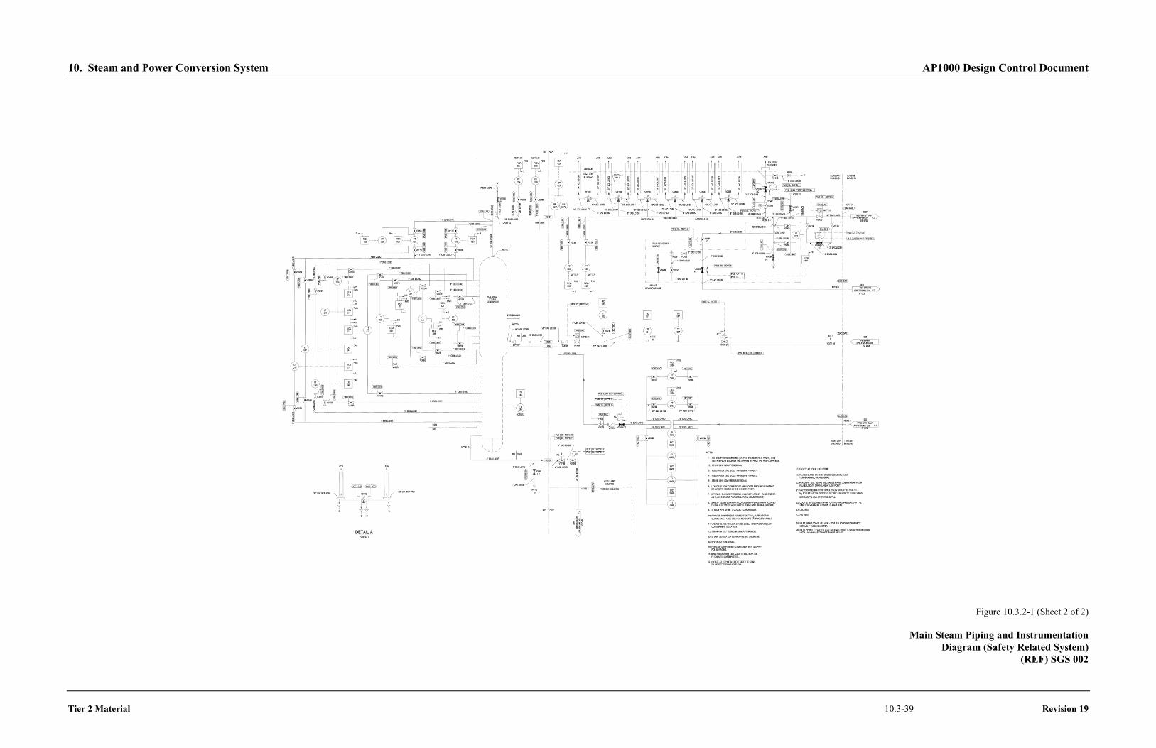
10. Steam and Power Conversion System AP1000 Design Control Document
Tier 2 Material 10.3-39 Revision 19
Figure 10.3.2-1 (Sheet 2 of 2)
Main Steam Piping and Instrumentation Diagram (Safety Related System)
(REF) SGS 002
10. Steam and Power Conversion System AP1000 Design Control Document
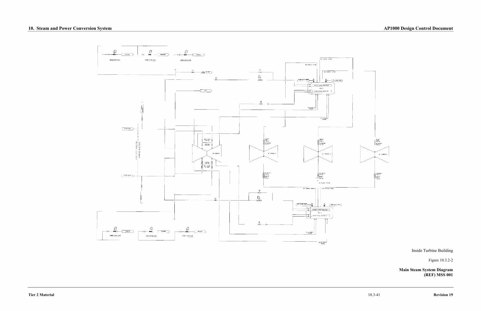
Tier 2 Material 10.3-41 Revision 19
Inside Turbine Building
Figure 10.3.2-2
Main Steam System Diagram (REF) MSS 001