
10. Applied Mathematics Course Description · 3.1/.$%&* * 3.1/.$%&* ' ' * * * * * * *
ESKOM Bantamsklip Transmission Line EIA March 2009 Draft Scoping Report – Application 1
3-1
3 DESCRIPTION OF THE PROPOSED DEVELOPMENT
3.1 Electricity transmission
3.1.1 Electrical power transmission and distributio n
Electricity is generated as it is used. Unlike other commodities, there is very little ability to store electricity. Because of the instantaneous nature of the electric system, constant modifications must be made to assure that the generation of power matches the consumption of power. The South African electric system is very complex and dynamic, and needs to be adjusted to meet changing needs. Electric power transmission, a process in the delivery of electricity to consumers, can be defined as the bulk transfer of electrical power. Typically, power transmission is between a Power Station and Substations that connect the national grid and end users. Electricity is transmitted over long distances at high voltage along transmission power lines from the Power Stations to the areas where it is needed. Electricity must be carried at high voltages (kilovolts, or kV) along transmission power lines in order to make up for losses that occur over long distances, and to limit the number of power lines required. In order for the electricity to be transmitted safely and efficiently over long distances, it must be at a high voltage (pressure) and a low current (flow). The voltages at which power is generated at the Power Stations are too low for transmission over long distances. To overcome this problem, transformers are installed at the power stations and substations to increase the voltage. Transformers step-up the voltage from, for example, 22kV to 220kV, 275kV, 400kV or 765 kV, and feed the electricity into Eskom’s national grid.
When the electricity arrives at a distribution Substation, bulk supplies of electricity are taken for primary distribution to towns and industrial areas, groups of villages, farms and similar concentrations of consumers. The lines are fed into intermediate Substations where transformers reduce the voltage. This could be 11kV in large factories and 380/220 volts in shops and homes. Power is distributed to end-users via reticulation power lines (See Figure 3.1 ).
In South Africa, Eskom has a total of 29 656 km (as of February 2009) of high voltage transmission lines. All the high voltage lines, plus the transformers and related equipment, form the transmission system also known as the national grid.

ESKOM Bantamsklip Transmission Line EIA March 2009 Draft Scoping Report – Application 1
3-2
Figure 3.1: Simplified electrical transmission and distribution system (source: www.eskom.co.za)
3.1.2 Components of a typical transmission line sys tem The main components of an electrical transmission system include the following:
(a) Transmission towers
Transmission towers are the most visible component of the power transmission system. Their function is to inter alia., keep the high-voltage conductors (power lines) separated from their surroundings and from each other. A variety of tower designs exist. Some tower designs reflect the specific function of the tower, while others have come about as a result of technological progress. Tower designs are discussed in Chapter 5 of this report; Figure 3.2 below highlights two different tower designs.

ESKOM Bantamsklip Transmission Line EIA March 2009 Draft Scoping Report – Application 1
3-3
Figure 3.2 : Photograph of Self-supporting Strain tower (in foreground) and Cross Rope Suspension tower (in centre) designs.
(b) Conductors Conductors are the power lines that carry the electricity to and through the grid. Generally, several conductors per phase are strung from tower to tower. The number of conductors per phase depends on the design for the line, typically 3 to 4 conductors per phase. Conductors are constructed primarily of metal or other types of materials as appropriate. An example is illustrated in Figure 3.3 .
Figure 3.3 : Photograph of conductors strung between transmission towers.
(c) Substations The very high voltages used for electric transmission are converted at Substations to lower voltages for consumer use. Substations vary in size and configuration but may

ESKOM Bantamsklip Transmission Line EIA March 2009 Draft Scoping Report – Application 1
3-4
cover several hectares; they are cleared of vegetation and typically surfaced with gravel. They are normally fenced, and are reached by a permanent access road. In general, substations include a variety of structures such as conductors, fencing, lighting, and other components (Figure 3.4 ).
Figure 3.4 : Photograph of a Substation, which transforms electricity from high to low voltage for consumer use. For the substation to perform it needs sophisticated protection equipment to detect faults and abnormal conditions. Action may consist for example, of automatically switching the power off and on again to cater for abnormal conditions such as lightning strikes or trees falling on lines. This action is necessary for safety reasons in the event of an accident or to keep the electricity supply constant.
(d) Transformers
A transformer is basically a very simple device (Figure 3.5 ). The alternating current is led through a primary coil of wire, which produces an alternating magnetic field in the ring-shaped core of soft iron. This in turn creates a voltage in a secondary coil, from which the output current can be drawn. If the secondary coil has more turns than the primary coil, the output voltage is higher than the input voltage. This is a step-up transformer. A step-down transformer has more turns in the primary coil than in the secondary coil to reduce the voltage.
ESKOM Bantamsklip Transmission Line EIA March 2009 Draft Scoping Report – Application 1
3-5
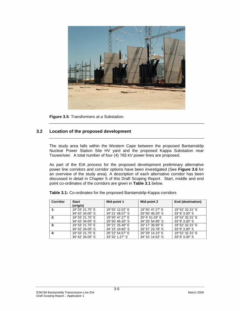
Figure 3.5 : Transformers at a Substation.
3.2 Location of the proposed development
The study area falls within the Western Cape between the proposed Bantamsklip Nuclear Power Station Site HV yard and the proposed Kappa Substation near Touwsrivier. A total number of four (4) 765 kV power lines are proposed. As part of the EIA process for the proposed development preliminary alternative power line corridors and corridor options have been investigated (See Figure 3.6 for an overview of the study area). A description of each alternative corridor has been discussed in detail in Chapter 5 of this Draft Scoping Report. Start, middle and end point co-ordinates of the corridors are given in Table 3.1 below.
Table 3.1: Co-ordinates for the proposed Bantamsklip-Kappa corridors
Corridor Start (origin)
Mid-point 1 Mid-point 2 End (destination)
1: 19° 33' 21.75" E 34° 42' 34.05" S
19° 55' 12.02" E 34° 21' 48.07" S
19° 50' 47.27" E 33° 50' 46.20" S
19° 52' 32.31" E 33° 8' 3.30" S
2: 19° 33' 21.75" E 34° 42' 34.05" S
19° 50' 47.27" E 33° 50' 46.20" S
20° 4' 51.03" E 34° 20' 54.95" S
19° 52' 32.31" E 33° 8' 3.30" S
3: 19° 33' 21.75" E 34° 42' 34.05" S
20° 21' 25.49" E 34° 15' 19.65" S
20° 17' 39.95" E 33° 37' 23.78" S
19° 52' 32.31" E 33° 8' 3.30" S
4: 19° 33' 21.75" E 34° 42' 34.05" S
20° 22' 54.57" E 33° 32' 1.27" S
20° 29' 14.15" E 34° 15' 14.52" S
19° 52' 32.31" E 33° 8' 3.30" S

ESKOM Bantamsklip Transmission Line EIA March 2009 Draft Scoping Report – Application 1
3-6
Figure 3.6: Study area for the Bantamsklip-Kappa power lines. This application falls within the eastern portion of the study area.
Table 3.2 provides information on the points of origin and destination of the proposed Bantamsklip-Kappa power line.
Table 3.2: Summary of points of origin and destination of the proposed power lines Name of power line
Origin of power line
Closest town / city (origin)
Destination of power line
Closest town / city (destination)
Bantamsklip-Kappa
Bantamsklip
Pearly Beach Kappa Substation Touws River
(a) Description of major towns and municipalities
The main towns which are situated along the approximately 227 to 258 km study routes are:
• Pearly Beach; • Bredasdorp; • Napier; • Klipdale; • Riviersonderend; • Swellendam; • Buffels; • Barrydale; • McGregor; • Bonnevale; • Ashton; • Robertson; • Montagu; and

ESKOM Bantamsklip Transmission Line EIA March 2009 Draft Scoping Report – Application 1
3-7
• Touws River. The local municipalities potentially affected by the proposed project include the:
• Overberg District Municipality (i.e. the southern sections of Bantamsklip-Kappa Alternatives 1, 2, 3 and 4); and
• Cape Winelands District Municipality (i.e. the northern sections of the Bantamsklip-Kappa Alternatives 1, 2, 3 and 4).
3.3 Description of the proposed development
3.3.1 Components of the transmission power lines
The proposed power lines are 765 kV transmission lines with four (4) lines proposed. A brief overview of the physical/technical requirements of the project is as follows: • Four (4) x 765 kV transmission power lines between Bantamsklip and Kappa. • Straight line distance between Bantamsklip and Kappa is approximately 227 to
258 km. • Servitude width for 1 x 765 kV power line = 80 m. • Servitude width for 4 x 765 kV power lines in parallel = 320 m • Height of 1 x 765kV power line = average of 48 m. • Minimum conductor clearance = between 8.5 – 10.4 m. • Span length between towers = approximately 450 m. The design of the 765kV towers and lines is unknown at present, as the choice is dependent on the conditions at the exact position of the transmission line on this chosen route. A description of the various tower alternatives has been included in Chapter 5. The actual number of towers required will vary according to the final route alignment determined. A working area of approximately 70 m x 50 m is needed for each of the proposed towers to be constructed.
3.3.2 Clearance requirements for transmission power lines For safety reasons, the transmission power lines require certain minimum clearance distances. These are as follows: • The minimum vertical clearance distance between the ground and the power
lines is 5.5 m. • The minimum vertical clearance to any fixed structure that does not form part
of the power line is 10.4 m - 11 m. • The minimum distance between a 765 kV power line and an existing road is
60 m – 120 m (depending on the type of road). Any farming activity can be practiced under the conductors provided that safe working clearances and building restrictions are adhered to.

ESKOM Bantamsklip Transmission Line EIA March 2009 Draft Scoping Report – Application 1
3-8
3.3.3 Proposed associated infrastructure to be cons tructed / erected The proposed development will require the following with respect to the permanent infrastructure: 1) Where the transmission line crosses a fence between neighbouring landowners
and there is no suitable gate in place, Eskom will erect a suitable gate in consultation with the landowner. These gates are necessary in order to ensure access to the line for maintenance and repair purposes. The installation and use of access gates is regulated through Eskom’s Gates Guideline TRMAGABE1 (Appendix C ).
2) Existing road infrastructure will be used as far as possible to provide access for construction vehicles during the construction of the line. Thereafter, the roads are used for inspection and maintenance purposes. Where appropriate roads may be upgraded to access transmission lines and substations.
3) Fuel 4) Fibre Optic cable could be strung on the earth cable if required for
telecommunication
3.3.4 Use of services and resources during construc tion (a) Water
Water will be required for potable use and in the construction of the foundations for the towers. The water will be sourced from approved water use points at locations closest to the area of construction.
(b) Sewage A negligible sewage flow is anticipated for the duration of the construction period. On site treatment will be undertaken through the use of chemical toilets. The toilets will be serviced periodically by the supplier.
(c) Roads Existing roads will be utilised as far as possible during the construction and operational periods. The use of roads on landowner property is subject to the Environmental Management Plan (EMP) and will be determined based on discussions with landowners during the negotiation process. In the event that areas are not accessible by road, access will be obtained for construction and maintenance activities via the utilisation of helicopters.
(d) Stormwater Stormwater will be managed according to the Eskom Guidelines for Erosion Control and Vegetation Management (see Appendix B ), as well as the Environmental Management Plan (EMP) that will be compiled for the construction phase.
(e) Solid waste disposal All solid waste will be collected at a central location at each construction site and will be stored temporarily until removal to an appropriately permitted landfill site in the vicinity of the construction site.

ESKOM Bantamsklip Transmission Line EIA March 2009 Draft Scoping Report – Application 1
3-9
(f) Electricity If required, substation sites have electrical connections via the distribution grid. Diesel generators may also be utilised for the provision of electricity during construction.
3.4 The steps in constructing and operating a tran smission power line
The typical steps involved in the construction and operation of a transmission power line is summarised in Table 3.3 .
Table 3.3: Typical steps in construction and operation of a transmission power line
3.4.1 Planning (Step 1) The System Planning Department, as the system network planners, formulate a five-year, ten-year or twenty-year Transmission Development Plan (TDP), which is a strategic document aimed at identifying all infrastructure required throughout South Africa for the transmission of electricity. All projects initiated by these planners will have to be in line with the requirements stipulated in the TDP. All initiated projects are thoroughly investigated to ensure that they are both viable and feasible before being approved for implementation. Once approved, the Land and Rights Department initiates the process of the environmental impact assessment (EIA).
3.4.2 Environmental impact assessment and authority authorisation of corridor (Step
2 and 3)
The EIA process forms part of the scope definition stage of a project. The aim of this process is to identify the possible routes where the project can be implemented with the minimal impact on the environment. The actual location of the towers across which the conductors (power lines) are spanned is determined by a number of factors, including Eskom negotiation with landowners, environmental features and technical requirements. As a result of these factors, it is impossible to predict the exact position of towers within the EIA process.
Step Activity 1 Determination of technically feasible alternative corridors 2 EIA of alternative corridors and recommendation on most preferred corridor 3 Authority authorisation of corridor 4 Negotiation of final route alignment within corridor with landowners 5 Aerial survey of the route 6 Selection of best-suited structures and foundations 7 Final design of line and placement of towers 8 Vegetation clearance and gate erection 9 Construction tender advertised and awarded 10 Establishment of construction camp and construction of access roads (if necessary) 11 Construction of foundations 12 Assembly and erection of towers 13 Stringing of conductors 14 Rehabilitation of working areas and protection of erosion susceptible area 15 Testing and commissioning of power line 16 Ongoing maintenance

ESKOM Bantamsklip Transmission Line EIA March 2009 Draft Scoping Report – Application 1
3-10
The inherent variation that is likely in the final placement of the towers is factored into the EIA through the assessment of power line corridors which are approximately five times the width of the final servitude actually required. A final EIR is produced and provided to the DEAT with all the alternative routes assessed during the EIA process. Recommendations for the least impacting route are provided for consideration during authorisation. The DEAT will issue an environmental authorisation based on the information provided. A project-specific Environmental Management Plan (EMP) is drafted for the project and this document details the specific controls which must be in place for the duration of the construction phase. An Environmental Control Officer (ECO) who acts as an intermediary between individual landowners, Eskom and the contractors, implements the EMP.
3.4.3 Negotiation and registration of a servitude ( Step 4)
The Bantamsklip-Kappa line will require the registration of a 80 m wide servitude (40 m either side of the centre-line) for each of the four transmission lines, across all land traversed by the proposed project. The servitudes do not imply that the holder of the servitude (Eskom) is the owner of the land but merely that the holder has a right to convey electricity over that land, subject to certain provisions. Registration of servitude can be a lengthy process, as it requires contractual negotiation with each affected landowner. Once this is complete, an application for registration of the servitude is lodged with the Registrar of Deeds to register the rights. Once Eskom exercises the option granted by the landowner, construction can commence. Sometimes construction starts before servitudes are registered at the Deeds office. For this reason Eskom pays the landowner a simple interest as determined by the Minister of Finance from the date of option to the date of registration.
3.4.4 Survey and line design (Steps 5 – 7)
Topographical surveys are conducted subsequent to identifying and securing the servitude. This is normally done by means of air-borne laser equipment to develop aerial photos. The topographical profile and plans are then used by the design engineers to design the tower foundations, structures, buildings, etc. All the above information would be required by the contractor before commencing construction.
3.4.5 Construction (Steps 8 – 13)
The final EMP will only be completed when all the profiles and site plans are available. This EMP will outline all activities that have to be undertaken, where they will take place, the responsible person/s, all possible environmental or social impacts, the mitigating measures, the rehabilitation plans, the monitoring methods, the frequency of monitoring and the performance indicators. This is a legally binding document which is used to ensure that Eskom adheres to all conditions of the Environmental Authorisation and EIR. Once this document has been approved by an authorised statutory body, the appointed contractor can commence construction.

ESKOM Bantamsklip Transmission Line EIA March 2009 Draft Scoping Report – Application 1
3-11
Figure 3.7 : Vegetation Clearance (Step 8)
Figure 3.8 : Gate Erection (access for maintenance phase) (Step 8)
Figure 3.9 : Access Roads (Step 10)

ESKOM Bantamsklip Transmission Line EIA March 2009 Draft Scoping Report – Application 1
3-12
Figure 3.10 : Construction Camp (Step 10)
Figure 3.11 : Construction of tower foundations (Step 11)
Figure 3.12 : Assembly and Erection of towers (Step 12)
Figure 3.13 : Stringing of conductors (power lines) (Step 13)

ESKOM Bantamsklip Transmission Line EIA March 2009 Draft Scoping Report – Application 1
3-13
3.4.6 Rehabilitation (Step 14) After the project has been completed, all affected properties are rehabilitated to as close to their original status as possible. Landowners sign off release forms to confirm the rehabilitated status.
3.4.7 Commissioning of the line and on-going mainte nance (Steps 15 – 16) Eskom technicians will test and commission the transmission lines once all the above steps have been completed. Maintenance of the lines and the surrounding servitude will take place on an on-going basis (Figure 3.14 – 3.15), as per the finalised operational EMP. Regular monitoring will also take place to ensure that this EMP is complied with effectively, and penalties will be enforced for non-compliance.
Figure 3.14 : Maintenance – Erosion Control
Figure 3.15 : Maintenance – Fire breaks
ESKOM Bantamsklip Transmission Line EIA March 2009 Draft Scoping Report – Application 1
3-14
3.5 Construction schedule
Construction of the proposed transmission lines is expected to commence in May 2010 and will take place over 26 – 28 months
3.6 Conclusion
This chapter provides a description of the proposed development and describes the various components of an electrical transmission system, namely; transmission towers, conductors, substations and transformers. This chapter further discusses the various associated infrastructure and the need for certain services and resources during construction. Finally, the various steps in constructing and operating a transmission power line are discussed and illustrated.


