B. DESCRIPTION OF PROPOSED PROJECT B.1 Introduction€¦ · South Bay Substation Relocation Project...
76
South Bay Substation Relocation Project B. Description of Proposed Project June 2012 B-1 Draft EIR B. DESCRIPTION OF PROPOSED PROJECT B.1 Introduction The proposed South Bay Substation Relocation Project (Proposed Project) includes the removal of the existing South Bay Substation, located in southwestern San Diego County (County) in the City of Chula Vista (City), and construction of a replacement substation (Bay Boulevard Substation) approximately 0.5 mile to the south of the existing South Bay Substation. The Proposed Project also includes the relocation and extension of existing utilities, which currently terminate at the South Bay Substation, in order to redirect the existing utilities to the proposed Bay Boulevard Substation. The proposed utility relocations and extensions that will accommodate the Bay Boulevard Substation include construction of a 230-kilovolt (kV) loop-in to existing 230 kV transmission lines located adjacent to the proposed Bay Boulevard Substation, relocation of the termination points of 69 kV transmission lines from the existing South Bay Substation (to be dismantled) to the proposed Bay Boulevard substation, and reconfiguring of existing 138 kV transmission lines that will be rerouted to the proposed substation (Bay Boulevard Substation) instead of terminating at the old South Bay Substation (to be dismantled). San Diego Gas & Electric Company (SDG&E) submitted an application to the California Public Utilities Commission (CPUC) for a Permit to Construct (PTC) for the purpose of developing the Proposed Project. The application and accompanying Proponent’s Environmental Assessment (PEA) describes the Proposed Project. B.2 Project Objectives SDG&E Project Objectives As stated by SDG&E and provided in Section A.2 of this EIR, the four project objectives for building the Proposed Project are to: • Replace aging and obsolete substation equipment • Design a flexible transmission system that would accommodate regional energy needs subsequent to retirement of the South Bay Power Plant (SBPP) • Facilitate the City’s bayfront redevelopment goals by relocating the South Bay Substation and furthering the goals of the SDG&E–City of Chula Vista Memorandum of Understanding (MOU) • Provide for future transmission and distribution load growth for the South Bay region.
Transcript of B. DESCRIPTION OF PROPOSED PROJECT B.1 Introduction€¦ · South Bay Substation Relocation Project...
South Bay Substation Relocation Project B. Description of Proposed Project
June 2012 B-1 Draft EIR
B. DESCRIPTION OF PROPOSED PROJECT
B.1 Introduction
The proposed South Bay Substation Relocation Project (Proposed Project) includes the removal of the existing South Bay Substation, located in southwestern San Diego County (County) in the City of Chula Vista (City), and construction of a replacement substation (Bay Boulevard Substation) approximately 0.5 mile to the south of the existing South Bay Substation. The Proposed Project also includes the relocation and extension of existing utilities, which currently terminate at the South Bay Substation, in order to redirect the existing utilities to the proposed Bay Boulevard Substation. The proposed utility relocations and extensions that will accommodate the Bay Boulevard Substation include construction of a 230-kilovolt (kV) loop-in to existing 230 kV transmission lines located adjacent to the proposed Bay Boulevard Substation, relocation of the termination points of 69 kV transmission lines from the existing South Bay Substation (to be dismantled) to the proposed Bay Boulevard substation, and reconfiguring of existing 138 kV transmission lines that will be rerouted to the proposed substation (Bay Boulevard Substation) instead of terminating at the old South Bay Substation (to be dismantled).
San Diego Gas & Electric Company (SDG&E) submitted an application to the California Public Utilities Commission (CPUC) for a Permit to Construct (PTC) for the purpose of developing the Proposed Project. The application and accompanying Proponent’s Environmental Assessment (PEA) describes the Proposed Project.
B.2 Project Objectives
SDG&E Project Objectives
As stated by SDG&E and provided in Section A.2 of this EIR, the four project objectives for building the Proposed Project are to:
• Replace aging and obsolete substation equipment
• Design a flexible transmission system that would accommodate regional energy needs subsequent to retirement of the South Bay Power Plant (SBPP)
• Facilitate the City’s bayfront redevelopment goals by relocating the South Bay Substation and furthering the goals of the SDG&E–City of Chula Vista Memorandum of Understanding (MOU)
• Provide for future transmission and distribution load growth for the South Bay region.
South Bay Substation Relocation Project B. Description of Proposed Project
June 2012 B-2 Draft EIR
B.3 Project Location
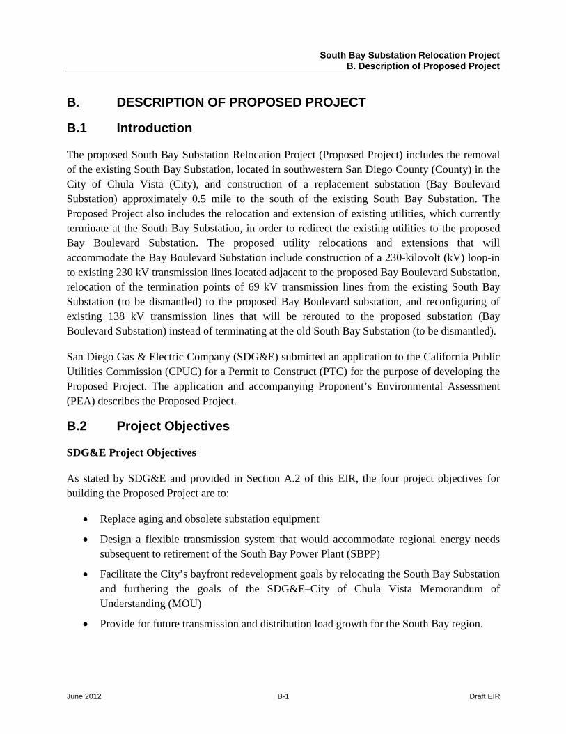
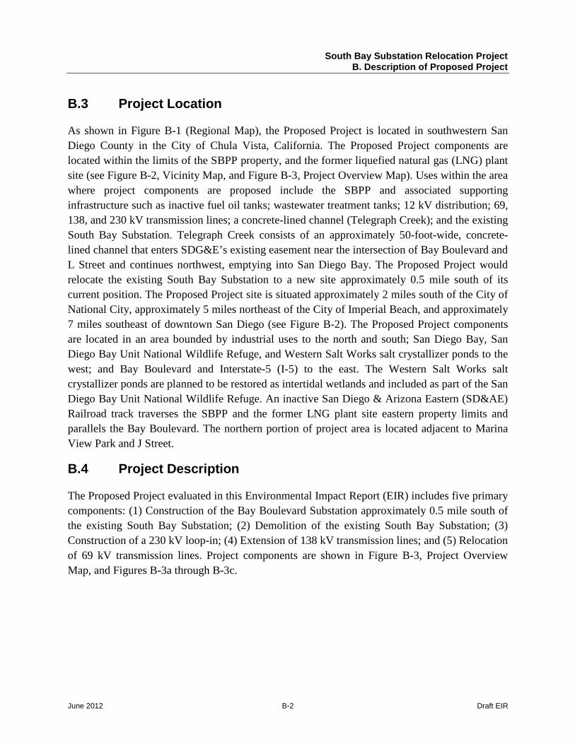
As shown in Figure B-1 (Regional Map), the Proposed Project is located in southwestern San Diego County in the City of Chula Vista, California. The Proposed Project components are located within the limits of the SBPP property, and the former liquefied natural gas (LNG) plant site (see Figure B-2, Vicinity Map, and Figure B-3, Project Overview Map). Uses within the area where project components are proposed include the SBPP and associated supporting infrastructure such as inactive fuel oil tanks; wastewater treatment tanks; 12 kV distribution; 69, 138, and 230 kV transmission lines; a concrete-lined channel (Telegraph Creek); and the existing South Bay Substation. Telegraph Creek consists of an approximately 50-foot-wide, concrete-lined channel that enters SDG&E’s existing easement near the intersection of Bay Boulevard and L Street and continues northwest, emptying into San Diego Bay. The Proposed Project would relocate the existing South Bay Substation to a new site approximately 0.5 mile south of its current position. The Proposed Project site is situated approximately 2 miles south of the City of National City, approximately 5 miles northeast of the City of Imperial Beach, and approximately 7 miles southeast of downtown San Diego (see Figure B-2). The Proposed Project components are located in an area bounded by industrial uses to the north and south; San Diego Bay, San Diego Bay Unit National Wildlife Refuge, and Western Salt Works salt crystallizer ponds to the west; and Bay Boulevard and Interstate-5 (I-5) to the east. The Western Salt Works salt crystallizer ponds are planned to be restored as intertidal wetlands and included as part of the San Diego Bay Unit National Wildlife Refuge. An inactive San Diego & Arizona Eastern (SD&AE) Railroad track traverses the SBPP and the former LNG plant site eastern property limits and parallels the Bay Boulevard. The northern portion of project area is located adjacent to Marina View Park and J Street.
B.4 Project Description
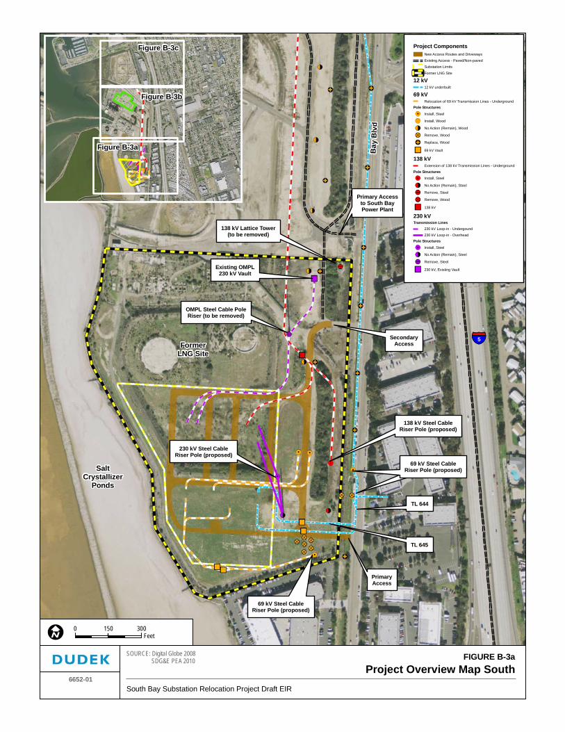
The Proposed Project evaluated in this Environmental Impact Report (EIR) includes five primary components: (1) Construction of the Bay Boulevard Substation approximately 0.5 mile south of the existing South Bay Substation; (2) Demolition of the existing South Bay Substation; (3) Construction of a 230 kV loop-in; (4) Extension of 138 kV transmission lines; and (5) Relocation of 69 kV transmission lines. Project components are shown in Figure B-3, Project Overview Map, and Figures B-3a through B-3c.
ImperialBeach
ChulaVista
NationalCity
Bonita
Coronado
LemonGrove
LaMesa
Poway
Encinitas
San Diego
Carlsbad
SanMarcos Escondido
VistaValleyCenter
Camp PendletonSouth Hidden
MeadowsOceanside
Bonsall
CampPendleton
North
Fallbrook
Rainbow
Jamul
Rancho SanDiegoSpring
Valley
Casa deOro-Mount Helix
AlpineHarbisonCanyon
Lakeside PineValley
El Cajon
Santee
Ramona San DiegoCountryEstates
Julian
BorregoSprings
SanClemente
DanaPoint
San JuanCapistrano
coHighlands
Temecula
Jacumba
Boulevard
Imperial County
Orange
County
San Diego
CountySan Diego County
San Diego County
Riverside County S a l t o nS e a
P a c i f i c
O c e a n
M E X I C OM E X I C O
195
274
78
209
163
56
75
1
98
52
111371
67
86
7679
94905
8
15
8
805
5
5
15
FIGURE B-1
Regional MapSouth Bay Substation Relocation Project Draft EIR
6652-01
0 155 10Miles
Project Site

South Bay Substation Relocation Project B. Description of Proposed Project
June 2012 B-4 Draft EIR
INTENTIONALLY LEFT BLANK
Existing South Bay Substation
Proposed BayBoulevard Substation
L StreetB
ay B
l vd
J Street
Marina View Park
Naples StreetFormer
LNG Site
South BayPower Plant
San Diego Bay
Chula VistaWildlife Reserve
San Diego Bay NationalWildlife Refuge -
San Diego Bay Unit
5
SanDiego
Coronado
NationalCity
Chula Vista
ImperialBeach
FIGURE B-2Vicinity Map
6652-01South Bay Substation Relocation Project Draft EIR
SOURCE: Digital Globe 2008 SDG&E PEA 2010
0 2,0001,000Feet

South Bay Substation Relocation Project B. Description of Proposed Project
June 2012 B-6 Draft EIR
INTENTIONALLY LEFT BLANK
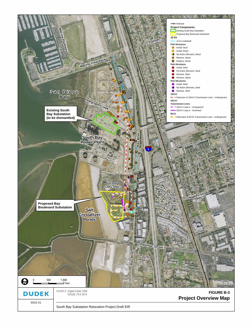
L Street
Bay
Blv
d
S a n D i e g oB a y
South BayPower Plant
Existing South Bay Substation(to be dismantled)
Proposed BayBoulevard Substation
J Street
Marina View Park
Marina Parkw
ay
Broadw
ay
Naples Street
SaltCrystallizer
Ponds
Bay
Bl v
d
Palomar Street
FormerLNG Site
Telegraph Creek
5
FIGURE B-3Project Overview Map
6652-01South Bay Substation Relocation Project Draft EIR
SOURCE: Digital Globe 2008 SDG&E PEA 2010
0 1,000500Feet
Railroad
Project ComponentsExisting South Bay SubstationProposed Bay Boulevard Substation
12 kV12 kV underbuilt
Pole StructuresInstall, SteelInstall, WoodNo Action (Remain), WoodRemove, WoodReplace, Wood
Pole StructuresInstall, SteelNo Action (Remain), SteelRemove, SteelRemove, Wood
Pole StructuresInstall, SteelNo Action (Remain), SteelRemove, Steel
138 kVExtension of 138 kV Transmission Lines - Underground
230 kVTransmission Lines
230 kV Loop-in - Undergound230 kV Loop-in - Overhead
69 kVRelocation of 69 kV Transmission Lines - Underground

South Bay Substation Relocation Project B. Description of Proposed Project
June 2012 B-8 Draft EIR
INTENTIONALLY LEFT BLANK
Ba y
Blv
d
PrimaryAccess
SaltCrystallizer
Ponds
FormerLNG Site
SecondaryAccess
Primary Accessto South BayPower Plant
OMPL Steel Cable PoleRiser (to be removed)
230 kV Steel CableRiser Pole (proposed)
138 kV Steel CableRiser Pole (proposed)
69 kV Steel CableRiser Pole (proposed)
69 kV Steel CableRiser Pole (proposed)
Existing OMPL230 kV Vault
138 kV Lattice Tower(to be removed)
TL 645
TL 644
5
FIGURE B-3aProject Overview Map South
6652-01South Bay Substation Relocation Project Draft EIR
SOURCE: Digital Globe 2008 SDG&E PEA 2010
0 300150Feet
Project ComponentsNew Access Routes and Driveways
Existing Access - Paved/Non-paved
Substation Limits
Former LNG Site
12 kV12 kV underbuilt
69 kVRelocation of 69 kV Transmission Lines - Underground
Pole Structures
Install, Steel
Install, Wood
No Action (Remain), Wood
Remove, Wood
Replace, Wood
69 kV Vault
138 kVExtension of 138 kV Transmission Lines - Underground
Pole StructuresInstall, Steel
No Action (Remain), Steel
Remove, Steel
Remove, Wood
138 kV
230 kVTransmission Lines
230 kV Loop-in - Undergound
230 kV Loop-in - OverheadPole Structures
Install, Steel
No Action (Remain), Steel
Remove, Steel
230 kV, Existing Vault
Figure B-3a
Figure B-3b
Figure B-3c

South Bay Substation Relocation Project B. Description of Proposed Project
June 2012 B-10 Draft EIR
INTENTIONALLY LEFT BLANK
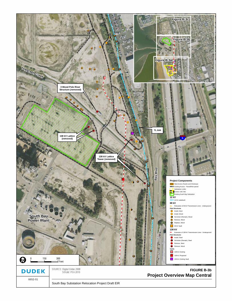
Bay
Blv
d
South BayPower Plant
Telegraph Creek
138 kV Lattice(removed)
3 Wood Pole RiserStructure (removed)
138 kV LatticeTower (removed)
levard
TL 644
5
FIGURE B-3bProject Overview Map Central
6652-01South Bay Substation Relocation Project Draft EIR
SOURCE: Digital Globe 2008 SDG&E PEA 2010
0 300150Feet
Project ComponentsNew Access Routes and Driveways
Existing Access - Paved/Non-pavedSubstation LimitsFormer LNG SiteExisting South Bay Substation
12 kV12 kV underbuilt
69 kVRelocation of 69 kV Transmission Lines - Underground
Pole StructuresInstall, Steel
Install, Wood
No Action (Remain), Wood
Remove, Wood
Replace, Wood
69 kV Vault
138 kVExtension of 138 kV Transmission Lines - Underground
Pole StructuresInstall, Steel
No Action (Remain), Steel
Remove, Steel
Remove, Wood
Vaults
138 kV, Existing
138 kV, Proposed
230 kV, Existing Vault
Figure B-3a
Figure B-3b
Figure B-3c

South Bay Substation Relocation Project B. Description of Proposed Project
June 2012 B-12 Draft EIR
INTENTONALLY LEFT BLANK
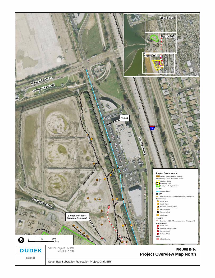
J Street
ark
Telegraph Creek
3 Wood Pole RiserStructure (removed)
Marina View ParkMarina ParkwayB
ay Boulevard
TL 644
5
FIGURE B-3cProject Overview Map North
6652-01South Bay Substation Relocation Project Draft EIR
SOURCE: Digital Globe 2008 SDG&E PEA 2010
0 300150Feet
Project ComponentsNew Access Routes and DrivewaysExisting Access - Paved/Non-pavedSubstation LimitsFormer LNG Site
Existing South Bay Substation
12 kV12 kV underbuilt
69 kVRelocation of 69 kV Transmission Lines - Underground
Pole StructuresInstall, Steel
Install, Wood
No Action (Remain), Wood
Remove, Wood
Replace, Wood
69 kV Vault
138 kVExtension of 138 kV Transmission Lines - Underground
Pole StructuresInstall, Steel
No Action (Remain), Steel
Remove, Steel
Remove, Wood
Vaults
138 kV, Existing
Figure B-3a
Figure B-3b
Figure B-3c

South Bay Substation Relocation Project B. Description of Proposed Project
June 2012 B-14 Draft EIR
INTENTIONALLY LEFT BLANK
South Bay Substation Relocation Project B. Description of Proposed Project
June 2012 B-15 Draft EIR
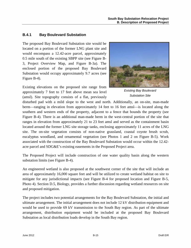
Existing Bay Boulevard Substation Site
B.4.1 Bay Boulevard Substation
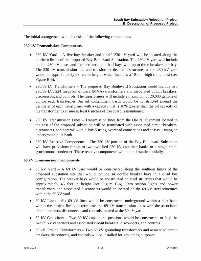
The proposed Bay Boulevard Substation site would be located on a portion of the former LNG plant site and would encompass a 12.42-acre parcel, approximately 0.5 mile south of the existing SBPP site (see Figure B-3, Project Overview Map, and Figure B-3a). The enclosed portion of the proposed Bay Boulevard Substation would occupy approximately 9.7 acres (see Figure B-4).
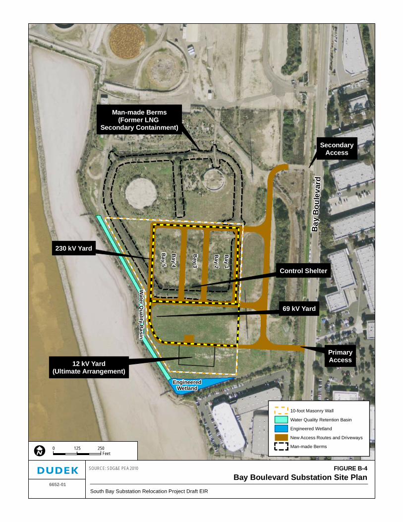
Existing elevations on the proposed site range from approximately 7 feet to 17 feet above mean sea level (amsl). Site topography consists of a flat, previously disturbed pad with a mild slope to the west and north. Additionally, an on-site, man-made berm—ranging in elevation from approximately 14 feet to 16 feet amsl—is located along the southern and western ends of the property, adjacent to a fence that bounds the property (see Figure B-4). There is an additional man-made berm in the west-central portion of the site that ranges in elevation from approximately 21 to 23 feet amsl and served as the containment basin located around the former LNG site storage tanks, enclosing approximately 11 acres of the LNG site. The on-site vegetation consists of non-native grassland, coastal coyote brush scrub, eucalyptus woodland, and ornamental vegetation (see Photos 1 and 2 on Figure B-5). Work associated with the construction of the Bay Boulevard Substation would occur within the 12.42-acre parcel and SDG&E’s existing easements in the Proposed Project area.
The Proposed Project will include construction of one water quality basin along the western substation limits (see Figure B-4).
An engineered wetland is also proposed at the southwest corner of the site that will include an area of approximately 16,000 square feet and will be utilized to create wetland habitat on site to mitigate for any jurisdictional impacts (see Figure B-4 for proposed location and Figure B-5, Photo 4). Section D.5, Biology, provides a further discussion regarding wetland resources on site and proposed mitigation.
The project includes two potential arrangements for the Bay Boulevard Substation, the initial and ultimate arrangement. The initial arrangement does not include 12 kV distribution equipment and would be used to provide 69 kV transmission to the South Bay region. As part of the ultimate arrangement, distribution equipment would be included at the proposed Bay Boulevard Substation as local distribution loads develop in the South Bay region.
South Bay Substation Relocation Project B. Description of Proposed Project
June 2012 B-16 Draft EIR
The initial arrangement would consist of the following components:
230 kV Transmission Components
• 230 kV Yard – A five-bay, breaker-and-a-half, 230 kV yard will be located along the northern limits of the proposed Bay Boulevard Substation. The 230 kV yard will include double 230 kV buses and five breaker-and-a-half bays with up to three breakers per bay. The 230 kV transmission line and transformer dead-end structures at the 230 kV yard would be approximately 68 feet in height, which includes a 10-foot-high static mast (see Figure B-6).
• 230/69 kV Transformers – The proposed Bay Boulevard Substation would include two 230/69 kV, 224 megavolt-ampere (MVA) transformers and associated circuit breakers, disconnects, and controls. The transformers will include a maximum of 20,000 gallons of oil for each transformer. An oil containment basin would be constructed around the perimeter of each transformer with a capacity that is 10% greater than the oil capacity of the transformer to ensure at least 6 inches of freeboard is maintained.
• 230 kV Transmission Lines – Transmission lines from the OMPL alignment located to the east of the proposed substation will be terminated with associated circuit breakers, disconnects, and controls within Bay 5 using overhead connections and at Bay 1 using an underground duct bank.
• 230 kV Reactive Components – The 230 kV portion of the Bay Boulevard Substation will have provisions for up to two switched 230 kV capacitor banks or a single small synchronous condenser. These reactive components will not be installed initially.
69 kV Transmission Components
• 69 kV Yard – A 69 kV yard would be constructed along the southern limits of the proposed substation site that would include 14 double breaker bays in a quad bus configuration. The breaker bays would be constructed on steel structures that would be approximately 45 feet in height (see Figure B-6). Two station lights and power transformers and associated disconnects would be located on the 69 kV steel structures within the 69 kV yard.
• 69 kV Lines – Six 69 kV lines would be constructed underground within a duct bank within the project limits to terminate the 69 kV transmission lines with the associated circuit breakers, disconnects, and controls located at the 69 kV yard.
• 69 kV Capacitors – Two 69 kV capacitors’ positions would be constructed to feed the two 69 kV capacitors and associated circuit breakers, disconnects, and controls.
• 69 kV Ground Transformers – Two 69 kV grounding transformers and associated circuit breakers, disconnects, and controls will be installed for grounding purposes.
Bay
Bou
leva
rd
Bay 1
Bay 2
Bay 3
Bay 4
Bay 5
SecondaryAccess
PrimaryAccess
230 kV Yard
69 kV Yard
EngineeredWetland
Water Q
uality Basin
Control Shelter
12 kV Yard(Ultimate Arrangement)
Man-made Berms(Former LNG
Secondary Containment)
FIGURE B-4Bay Boulevard Substation Site Plan
6652-01South Bay Substation Relocation Project Draft EIR
SOURCE: SDG&E PEA 2010
0 250125Feet
10-foot Masonry Wall
Water Quality Retention Basin
Engineered Wetland
New Access Routes and Driveways
Man-made Berms

South Bay Substation Relocation Project B. Description of Proposed Project
June 2012 B-18 Draft EIR
INTENTIONALLY LEFT BLANK
Proposed BayBoulevard Substation
Photo Points
1
2
3
4
Bay
Blv
d
5
FIGURE B-5Bay Boulevard Substation Site Photos
6652-01South Bay Substation Relocation Project Draft EIR
SOURCE: Digital Globe 2008 SDG&E PEA 2010
0 400200Feet
Photo 1: View of Bay Boulevard Substation Site Looking North Photo 2: View of Bay Boulevard Substation Site Looking Northeast
Photo 3: View of 230 kV Tangent Pole Structure Looking East Photo 4: View of Engineered Wetland Looking West

South Bay Substation Relocation Project B. Description of Proposed Project
June 2012 B-20 Draft EIR
INTENTIONALLY LEFT BLANK
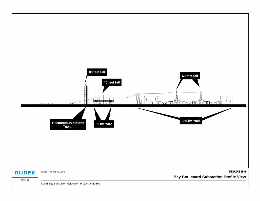
FIGURE B-6
Bay Boulevard Substation Profile ViewSouth Bay Substation Relocation Project Draft EIR
6652-01
SOURCE: SDG&E PEA 2010
83 feet tall
45 feet tall
68 feet tall
TelecommunicationsTower
69 kV Yard230 kV Yard

South Bay Substation Relocation Project B. Description of Proposed Project
June 2012 B-22 Draft EIR
INTENTIONALLY LEFT BLANK
South Bay Substation Relocation Project B. Description of Proposed Project
June 2012 B-23 Draft EIR
Communications Tower
• A communications tower is proposed along the southern edge of the substation limits to support a microwave telecommunication disc that would be used by SDG&E to monitor the substation operations remotely. The communication tower would include a 75-foot-tall lattice steel tower to support an 8-foot-diameter microwave telecommunications disc (see Figure B-6. An area measuring approximately 12 feet wide by 20 feet long and 12 feet tall would be located adjacent to the structure to house communication equipment.
Control House
• A transmission control house measuring approximately 32 feet wide by 50 feet long and 12 feet tall would be constructed within the central portion of the site between the 69 kV bays and 230 kV bays. The structure is required in order to house substation controls and protection and is typically constructed of masonry blocks.
As shown in Figure B-4, the ultimate arrangement would consist of all the components constructed as part of the initial arrangement with the addition of the following components:
230 kV Transmission Components
• 230 kV Transmission Lines – Transmission lines from the OMPL alignment located east of the proposed substation will be terminated with associated circuit breakers, disconnects, and controls at Bays 1, 2, and 4 with underground duct banks and Bay 5 with overhead conductors. There will be a total of five new connections under the ultimate arrangement with two new overhead circuit connections at Bay 5, one underground connection each at Bays 1, 2, and 4.
• 230/69 kV Transformers – The ultimate arrangement would include the addition of one 230/69 kV 224 MVA transformer and associated circuit breakers, disconnects, and controls for a total of three transformers on site. Each 230/69 kV transformer will require approximately 20,000 gallons of oil. An oil containment basin would be constructed around the perimeter of each transformer with a capacity that is 10% greater than the oil capacity of the transformer to ensure at least 6 inches of freeboard is maintained.
• 230 kV Reactive Components – Two 230 kV capacitors or one 230 kV synchronous condenser installation would be constructed along with associated circuit breakers, disconnects, and controls.
South Bay Substation Relocation Project B. Description of Proposed Project
June 2012 B-24 Draft EIR
69 kV Transmission Components
• 69 kV Lines – Six underground transmission lines would be constructed in addition to those for the initial arrangement, along with associated circuit breakers, disconnects, and controls for a total of twelve 69 kV transmission lines.
• 69/12 kV Transformers – The ultimate arrangement would include the addition of four 69/12 kV, 28 MVA transformers, associated switchgear, capacitor banks, and controls. An oil containment basin would be constructed around the perimeter of each transformer with a capacity that is 10% greater than the oil capacity of the transformer to ensure at least 6 inches of freeboard is maintained.
Control House
• A new distribution control house, in addition to the one that will be constructed under the initial arrangement, measuring approximately 20 feet wide by 40 feet long and 12 feet tall would be constructed to the south between the 69 kV bays and 12 kV distribution equipment. The structure is required to house substation controls and protection and is typically constructed of masonry blocks.
12 kV Distribution
• 12 kV Lines – Sixteen 12 kV distribution lines would be installed using an underground duct bank beneath the southern access road to the Bay Boulevard site.
• 12 kV Capacitors – Four 12 kV capacitors would be constructed along with associated circuit breakers, disconnects, and controls.
Lighting: The Bay Boulevard Substation would include approximately fifteen 175-watt tungsten-quartz lamps placed adjacent to substation equipment to allow inspections to be completed and provide for safe movement within the substation limits. Lighting on site would also include four 75-watt lights around each control shelter. Since maintenance activities are not anticipated to be completed during the evening hours, lights would only be turned on if needed. A 100-watt yellow floodlight would be mounted at both the southern and northern entrance gates to allow for safe entry and would remain lit during nighttime hours. All lights would be directed downward to minimize the potential for spillover to adjacent properties and habitat.
South Bay Substation Relocation Project B. Description of Proposed Project
June 2012 B-25 Draft EIR
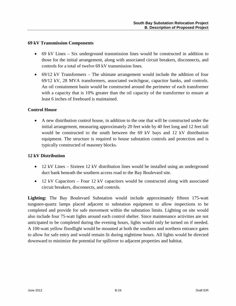
Class II Aggregate Roadways
Access Roads: As shown in Figure B-3a, primary access to the Bay Boulevard Substation site will be provided from Bay Boulevard located to the east. A main access driveway would be constructed from Bay Boulevard, at the south end of the LNG site, to the proposed Bay Boulevard Substation. There will be three gated entrances located along the eastern perimeter of the substation that will provide ingress/egress to the substation from Bay Boulevard. The main access driveway entrance will be the central gate with alternate points of access located to the south and north of the central gate. The central gate will be utilized to provide primary access to the substation during operation and maintenance activities. An access road will be constructed to provide a connection to all three gated entrances and would extend west from Bay Boulevard for approximately 160 feet. The access route would then turn north and parallel the eastern perimeter of the substation. Three driveways would extend from the main access route to three gated entrances (south, central, and north) and the substation’s interior paved roads. The existing paved entrance from Bay Boulevard to the LNG site located to the north is planned to be improved to provide construction and secondary access to the Bay Boulevard Substation. The existing route leads west from Bay Boulevard for approximately 160 feet. From this point, the secondary access route would turn to the south and head toward the Bay Boulevard Substation where it would connect to the main access route.
With the exception of the main access route’s initial approximately 20-foot-long concrete apron, the access roads, driveways, and interior substation access roads will be approximately 30 feet wide and bordered by approximately 3-foot-wide, Class II aggregate shoulders. The main access route will be asphalt-paved between the end of the 20-foot-long concrete apron from Bay Boulevard and the central and southern substation gates. The remainder of the access routes and driveways north of the central gate will have a graded Class II aggregate road surface.
The southern access road will traverse a drainage channel located along the western limits of Bay Boulevard. To ensure that flows will be maintained along this drainage channel, located adjacent to Bay Boulevard, a box culvert will be constructed.
Prior to construction of the new primary access road to Bay Boulevard, underground duct banks would be constructed under the primary access road between the eastern limits of the proposed substation and Bay Boulevard, a length of approximately 355 feet. Each of these duct banks would include six 6-inch-diameter and one approximately 4-inch-diameter polyvinylchloride (PVC) conduits for the ultimate arrangement, which includes 12 kV distribution equipment.
South Bay Substation Relocation Project B. Description of Proposed Project
June 2012 B-26 Draft EIR
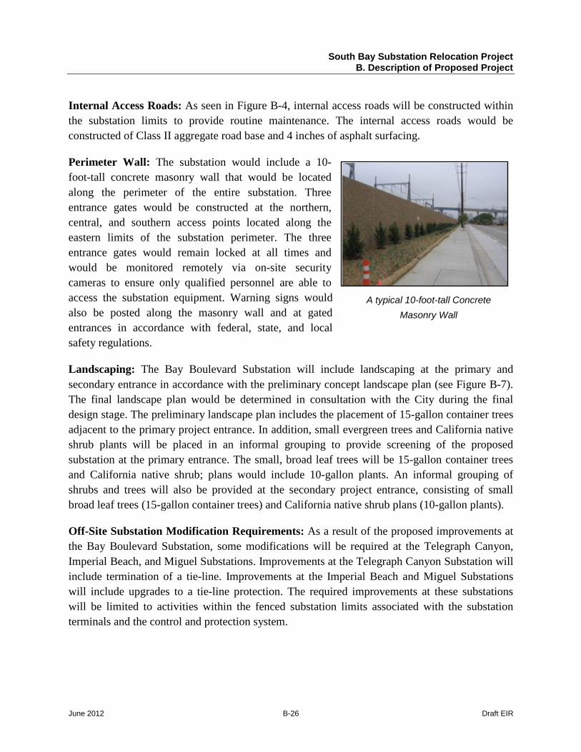
A typical 10-foot-tall Concrete Masonry Wall
Internal Access Roads: As seen in Figure B-4, internal access roads will be constructed within the substation limits to provide routine maintenance. The internal access roads would be constructed of Class II aggregate road base and 4 inches of asphalt surfacing.
Perimeter Wall: The substation would include a 10-foot-tall concrete masonry wall that would be located along the perimeter of the entire substation. Three entrance gates would be constructed at the northern, central, and southern access points located along the eastern limits of the substation perimeter. The three entrance gates would remain locked at all times and would be monitored remotely via on-site security cameras to ensure only qualified personnel are able to access the substation equipment. Warning signs would also be posted along the masonry wall and at gated entrances in accordance with federal, state, and local safety regulations.
Landscaping: The Bay Boulevard Substation will include landscaping at the primary and secondary entrance in accordance with the preliminary concept landscape plan (see Figure B-7). The final landscape plan would be determined in consultation with the City during the final design stage. The preliminary landscape plan includes the placement of 15-gallon container trees adjacent to the primary project entrance. In addition, small evergreen trees and California native shrub plants will be placed in an informal grouping to provide screening of the proposed substation at the primary entrance. The small, broad leaf trees will be 15-gallon container trees and California native shrub; plans would include 10-gallon plants. An informal grouping of shrubs and trees will also be provided at the secondary project entrance, consisting of small broad leaf trees (15-gallon container trees) and California native shrub plans (10-gallon plants).
Off-Site Substation Modification Requirements: As a result of the proposed improvements at the Bay Boulevard Substation, some modifications will be required at the Telegraph Canyon, Imperial Beach, and Miguel Substations. Improvements at the Telegraph Canyon Substation will include termination of a tie-line. Improvements at the Imperial Beach and Miguel Substations will include upgrades to a tie-line protection. The required improvements at these substations will be limited to activities within the fenced substation limits associated with the substation terminals and the control and protection system.
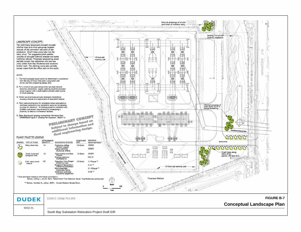
FIGURE B-7
Conceptual Landscape PlanSouth Bay Substation Relocation Project Draft EIR
6652-01
SOURCE: SDG&E PEA 2010

South Bay Substation Relocation Project B. Description of Proposed Project
June 2012 B-28 Draft EIR
INTENTIONALLY LEFT BLANK
South Bay Substation Relocation Project B. Description of Proposed Project
June 2012 B-29 Draft EIR
B.4.2 South Bay Substation Dismantling
The Proposed Project would include decommissioning and demolition of the existing 7.22-acre South Bay Substation following several conditional requirements such as energization of the Bay Boulevard Substation, and cutovers of the existing transmission lines from the South Bay Substation to the Bay Boulevard Substation. SDG&E would also be required to receive approval of a demolition plan by the Port District prior to completion of demolition activities through the Tenant Approval Process.
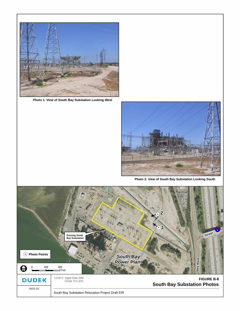
The decommissioning and demolition of the South Bay Substation would include removal of all above-grade components, including both 138 kV and 69 kV transmission equipment (see Figure B-3c and Figure B-8, South Bay Substation Photos).
Work associated with demolition of the existing South Bay Substation would occur within current substation boundaries and in an area extending approximately 50 feet from existing substation boundaries. Substation components to be removed include the control houses, steel support structures, and electrical substation equipment, and supporting foundations would be removed to approximately 6 feet below existing grade. Following demolition and decommissioning of the substation components, the substation area would be graded to blend with the surrounding topography.
The demolition of the South Bay Substation and decommissioning of the SBPP could occur simultaneously. The South Bay Substation includes some equipment associated with the operations of the SBPP, such as circuit breakers, disconnect switches, structures, foundations, relay panels, and cabling. Removal of this equipment would be completed as part of the SBPP decommissioning and is not proposed as part of this project. Attachment 3-E of the SDG&E PEA (2010a) provides an overview of the equipment located within the South Bay Substation property limits and the associated owner. The project does not include removal of any other equipment or underground utilities that are not connected to the South Bay Substation, such as gas lines located within the SBPP property limits.
South Bay Substation Relocation Project B. Description of Proposed Project
June 2012 B-30 Draft EIR
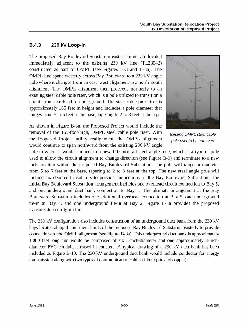
Existing OMPL steel cable pole riser to be removed
B.4.3 230 kV Loop-In
The proposed Bay Boulevard Substation eastern limits are located immediately adjacent to the existing 230 kV line (TL23042) constructed as part of OMPL (see Figures B-3 and B-3a). The OMPL line spans westerly across Bay Boulevard to a 230 kV angle pole where it changes from an east–west alignment to a north–south alignment. The OMPL alignment then proceeds northerly to an existing steel cable pole riser, which is a pole utilized to transition a circuit from overhead to underground. The steel cable pole riser is approximately 165 feet in height and includes a pole diameter that ranges from 5 to 6 feet at the base, tapering to 2 to 3 feet at the top.
As shown in Figure B-3a, the Proposed Project would include the removal of the 165-foot-high, OMPL steel cable pole riser. With the Proposed Project utility realignment, the OMPL alignment would continue to span northward from the existing 230 kV angle pole to where it would connect to a new 110-foot-tall steel angle pole, which is a type of pole used to allow the circuit alignment to change direction (see Figure B-9) and terminate to a new rack position within the proposed Bay Boulevard Substation. The pole will range in diameter from 5 to 6 feet at the base, tapering to 2 to 3 feet at the top. The new steel angle pole will include six dead-end insulators to provide connections of the Bay Boulevard Substation. The initial Bay Boulevard Substation arrangement includes one overhead circuit connection to Bay 5, and one underground duct bank connection to Bay 1. The ultimate arrangement at the Bay Boulevard Substation includes one additional overhead connection at Bay 5, one underground tie-in at Bay 4, and one underground tie-in at Bay 2. Figure B-3a provides the proposed transmission configuration.
The 230 kV configuration also includes construction of an underground duct bank from the 230 kV bays located along the northern limits of the proposed Bay Boulevard Substation easterly to provide connections to the OMPL alignment (see Figure B-3a). This underground duct bank is approximately 1,000 feet long and would be composed of six 8-inch-diameter and one approximately 4-inch-diameter PVC conduits encased in concrete. A typical drawing of a 230 kV duct bank has been included as Figure B-10. The 230 kV underground duct bank would include conductor for energy transmission along with two types of communication cables (fiber optic and copper).
Existing SouthBay Substation
Photo Points
1
2
Bay
Blv
dSouth BayPower Plant
L Street5
FIGURE B-8South Bay Substation Photos
6652-01South Bay Substation Relocation Project Draft EIR
SOURCE: Digital Globe 2008 SDG&E PEA 2010
0 400200Feet
Photo 1: View of South Bay Substation Looking West
Photo 2: View of South Bay Substation Looking South

South Bay Substation Relocation Project B. Description of Proposed Project
June 2012 B-32 Draft EIR
INTENTIONALLY LEFT BLANK
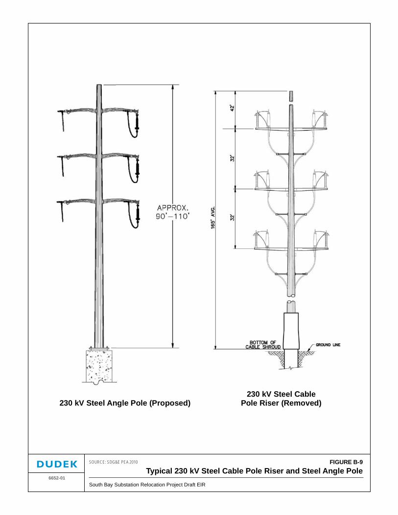
FIGURE B-9Typical 230 kV Steel Cable Pole Riser and Steel Angle Pole
6652-01South Bay Substation Relocation Project Draft EIR
SOURCE: SDG&E PEA 2010
230 kV Steel Angle Pole (Proposed)230 kV Steel Cable
Pole Riser (Removed)

South Bay Substation Relocation Project B. Description of Proposed Project
June 2012 B-34 Draft EIR
INTENTIONALLY LEFT BLANK
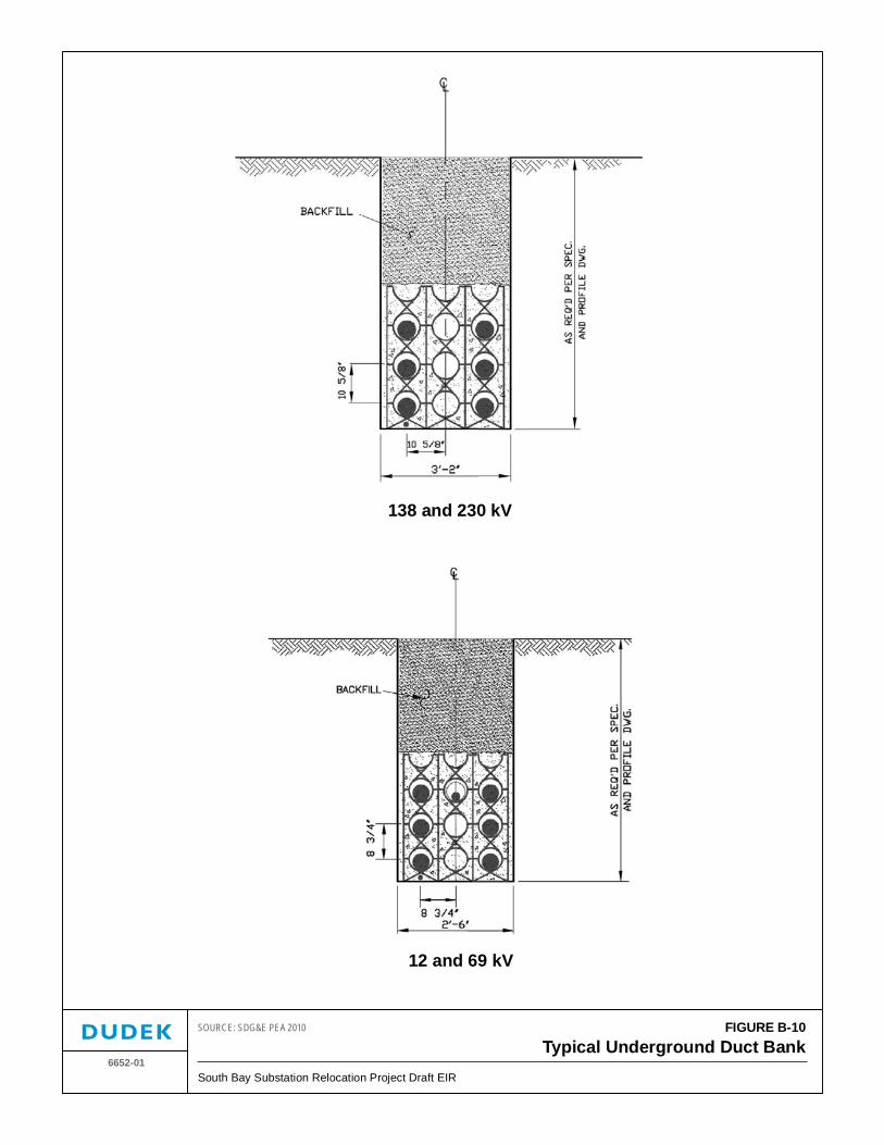
FIGURE B-10Typical Underground Duct Bank
6652-01South Bay Substation Relocation Project Draft EIR
SOURCE: SDG&E PEA 2010
138 and 230 kV
12 and 69 kV

South Bay Substation Relocation Project B. Description of Proposed Project
June 2012 B-36 Draft EIR
INTENTIONALLY LEFT BLANK
South Bay Substation Relocation Project B. Description of Proposed Project
June 2012 B-37 Draft EIR
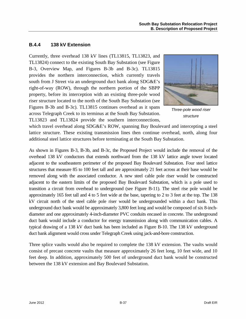
Three-pole wood riser structure
B.4.4 138 kV Extension
Currently, three overhead 138 kV lines (TL13815, TL13823, and TL13824) connect to the existing South Bay Substation (see Figure B-3, Overview Map, and Figures B-3b and B-3c). TL13815 provides the northern interconnection, which currently travels south from J Street via an underground duct bank along SDG&E’s right-of-way (ROW), through the northern portion of the SBPP property, before its interception with an existing three-pole wood riser structure located to the north of the South Bay Substation (see Figures B-3b and B-3c). TL13815 continues overhead as it spans across Telegraph Creek to its terminus at the South Bay Substation. TL13823 and TL13824 provide the southern interconnections, which travel overhead along SDG&E’s ROW, spanning Bay Boulevard and intercepting a steel lattice structure. These existing transmission lines then continue overhead, north, along four additional steel lattice structures before terminating at the South Bay Substation.
As shown in Figures B-3, B-3b, and B-3c, the Proposed Project would include the removal of the overhead 138 kV conductors that extends northward from the 138 kV lattice angle tower located adjacent to the southeastern perimeter of the proposed Bay Boulevard Substation. Four steel lattice structures that measure 85 to 100 feet tall and are approximately 21 feet across at their base would be removed along with the associated conductor. A new steel cable pole riser would be constructed adjacent to the eastern limits of the proposed Bay Boulevard Substation, which is a pole used to transition a circuit from overhead to underground (see Figure B-11). The steel rise pole would be approximately 165 feet tall and 4 to 5 feet wide at the base, tapering to 2 to 3 feet at the top. The 138 kV circuit north of the steel cable pole riser would be undergrounded within a duct bank. This underground duct bank would be approximately 3,800 feet long and would be composed of six 8-inch-diameter and one approximately 4-inch-diameter PVC conduits encased in concrete. The underground duct bank would include a conductor for energy transmission along with communication cables. A typical drawing of a 138 kV duct bank has been included as Figure B-10. The 138 kV underground duct bank alignment would cross under Telegraph Creek using jack-and-bore construction.
Three splice vaults would also be required to complete the 138 kV extension. The vaults would consist of precast concrete vaults that measure approximately 26 feet long, 10 feet wide, and 10 feet deep. In addition, approximately 500 feet of underground duct bank would be constructed between the 138 kV extension and Bay Boulevard Substation.

South Bay Substation Relocation Project B. Description of Proposed Project
June 2012 B-38 Draft EIR
B.4.5 69 kV Relocation
Currently, six 69 kV overhead transmission lines connect into the existing South Bay Substation. Three of these lines (TL645, TL646, and TL647) enter the Proposed Project area from the south. The remaining three overhead transmission lines (TL641, TL642, and TL644) connect to the existing South Bay Substation from the north. These overhead transmission lines are shown on Figure B-3, Project Overview Map, and Figures B-3a through B-3c.
The Proposed Project includes rerouting existing 69 kV overhead transmission lines that terminate at the South Bay Substation to the proposed Bay Boulevard Substation. In order to relocate these six existing 69 kV overhead transmission lines, approximately 18 new wood transmission poles would be installed, 23 wood transmission poles would be removed, and an additional 22 wood transmission poles would be replaced. The project also includes construction of five 69 kV steel cable pole risers, removal of six stub wood poles, and removal of one 12 kV wood distribution pole.
An existing 12 kV distribution circuit located along Bay Boulevard will be underbuilt onto the 69 kV poles located along Bay Boulevard. The alignment of the 12 kV distribution circuits that will be placed beneath the 69 kV conductor will be along TL 644, which runs north–south along the western limits of Bay Boulevard and TL 645, which runs east–west along an easement adjacent to the northern limits of the OMPL. Figures B-3a through B-3c provide an overview of the locations for new wood poles, removal of wood poles, and replacement of existing wood poles. Attachment 3-D of the SDG&E PEA (2010a) includes a detailed description of each wood pole in the project area including location and ultimate proposed configuration.
The 69 kV relocation component of the project includes four types of poles to be constructed. These include an angle pole (dead-end pole), which is installed in locations where the transmission line must change direction. Tangent poles will also be constructed, which are used in areas where the transmission line is generally straight. In areas where poles require additional stability due to the localized terrain or where the line tension at angle poles has dictated the need for more stability, stub wood poles and guy wires would be connected to the poles. The 69 kV wood poles that will be installed, removed, or replaced would all vary in height from 60 to 75 feet. The height of the poles to be replaced and/or installed would be consistent with the pole structures supporting the existing 69 kV transmission lines in the area. Figure B-12 provides a typical drawing of the poles that would be removed and installed as part of the project.
The construction of five new steel cable pole risers (approximately 85 feet tall) would also be required. These poles are used to transition overhead conductor to underground. As seen in Figure B-3a, three steel cable pole risers would be constructed within the limits of the existing SDG&E easement, adjacent to the proposed Bay Boulevard Substation property on the east, and two steel cable pole risers will be located in the franchise corridor along the Bay Boulevard ROW to the north of the new primary entrance drive to the Bay Boulevard Substation.
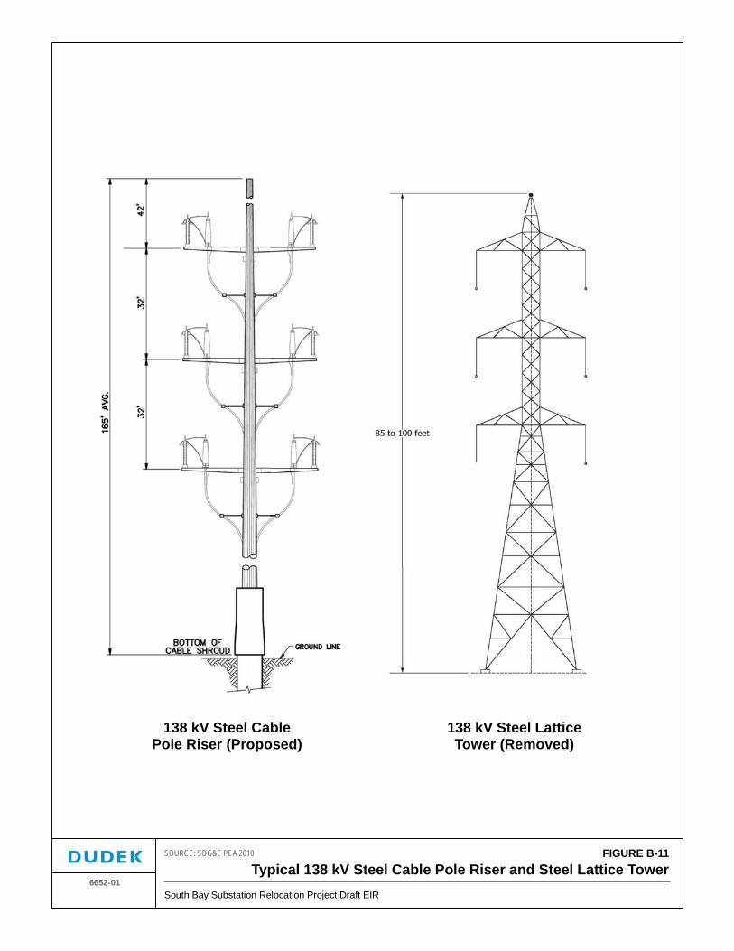
FIGURE B-11Typical 138 kV Steel Cable Pole Riser and Steel Lattice Tower
6652-01South Bay Substation Relocation Project Draft EIR
SOURCE: SDG&E PEA 2010
138 kV Steel CablePole Riser (Proposed)
138 kV Steel LatticeTower (Removed)

South Bay Substation Relocation Project B. Description of Proposed Project
June 2012 B-40 Draft EIR
INTENTIONALLY LEFT BLANK
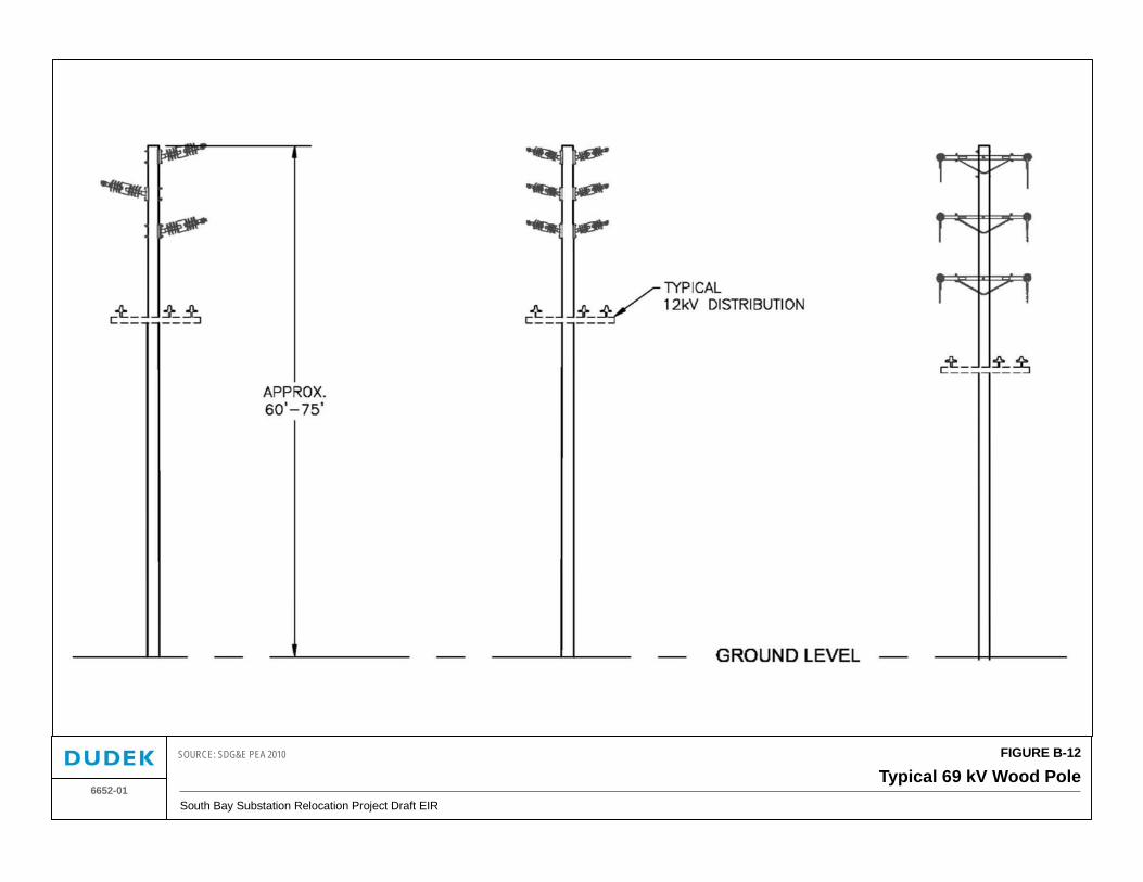
FIGURE B-12
Typical 69 kV Wood PoleSouth Bay Substation Relocation Project Draft EIR
6652-01
SOURCE: SDG&E PEA 2010

South Bay Substation Relocation Project B. Description of Proposed Project
June 2012 B-42 Draft EIR
INTENTIONALLY LEFT BLANK
South Bay Substation Relocation Project B. Description of Proposed Project
June 2012 B-43 Draft EIR
Southern 69 kV Transmission Lines: Three overhead lines (TL645, TL646, and TL647) would be rerouted to the proposed Bay Boulevard Substation.
TL645 would be intercepted using a new steel cable pole riser, located directly to the west of and adjacent to Bay Boulevard (see Figure B-13). The 69 kV steel cable pole riser would be approximately 85 feet tall. TL645 would then transition at the steel cable pole riser to an underground duct bank, which would travel south within Bay Boulevard for approximately 120 feet before heading west, crossing under a drainage and the SD&AE railroad tracks, and entering the Bay Boulevard Substation. The underground duct bank would be composed of approximately six 6-inch-diameter and one approximately 4-inch-diameter PVC conduit encased in concrete. Figure B-10 includes a typical drawing of the proposed underground duct bank. TL645 would also include the construction of two underground concrete splice vaults located adjacent to the western limits of the proposed substation. The precast concrete splice vault would measure approximately 17 feet long, 9 feet wide, and 11 feet deep. An existing 12 kV distribution circuit located along Bay Boulevard will be underbuilt onto the 69 kV poles located along TL 645.
TL646 and TL647 would be intercepted using a new steel cable pole riser located adjacent to Bay Boulevard approximately 200 feet east of the proposed substation (see Figure B-13). TL646 and TL647 would then transition at the steel cable pole riser to an underground duct bank measuring approximately 1,000 feet long that would travel west. As described under TL645, the underground duct bank would be composed of approximately six 6-inch-diameter and one approximately 4-inch-diameter PVC conduit encased in concrete. TL646 and TL647 would also include the construction of two underground concrete splice vaults located adjacent to the southern limits of the proposed substation.
Northern 69 kV Transmission Lines: Overhead lines TL641, TL642, and TL644 would be rerouted from the South Bay Substation to the proposed Bay Boulevard Substation.
TL641 consists of overheard transmission lines that run north–south within the 300-foot easement located along the eastern limits of the SBPP property and the 300-foot easement within the property of the former LNG plant. In order to relocate the 69 kV tie- line from the South Bay Substation to the proposed Bay Boulevard Substation, two wood poles would need to be replaced, six new wood poles would be installed, and one new steel cable pole riser would be installed adjacent to the eastern limits of the Bay Boulevard Substation. The 69 kV steel cable pole riser would be approximately 85 feet tall. TL645 would then transition at the steel cable pole riser to an underground duct bank for approximately 700 feet where it will dead-end at the proposed Bay Boulevard Substation.
TL642 consists of overhead transmission lines that run north–south within the 300-foot easement along the eastern limits of the SBPP property and the 300-foot easement within the property of the former LNG plant. In order to relocate the 69 kV tie-line from the South Bay Substation to
South Bay Substation Relocation Project B. Description of Proposed Project
June 2012 B-44 Draft EIR
the proposed Bay Boulevard Substation, seven wood poles would need to be replaced, three new wood poles would be installed, and one new steel pole would be installed adjacent to the eastern limits of the Bay Boulevard Substation. The 69 kV steel cable pole riser would be approximately 85 feet tall. TL642 would then transition at the steel cable pole riser to an underground duct bank for approximately 600 feet where it will terminate at the proposed Bay Boulevard Substation.
TL644 consists of overhead transmission lines that run north–south within the 300-foot easement along the eastern limits of the SBPP property. TL644 transitions from within the SBPP easement to SDG&E’s franchise corridor along the western ROW limits of Bay Boulevard at the Bay Boulevard and L Street interchange. In order to relocate the 69 kV tie-line from the South Bay Substation to the proposed Bay Boulevard Substation, thirteen wood poles would need to be replaced and two new wood poles and one new steel cable pole riser would be installed along Bay Boulevard adjacent to the proposed primary access for the Bay Boulevard Substation. An existing 12 kV distribution circuit located along Bay Boulevard will be underbuilt onto the 69 kV poles located along TL 644. TL644 would transition from aboveground to underground at the new 69 kV steel cable pole riser that would be approximately 85 feet tall. TL644 would then be undergrounded south to the new primary access drive location and then turn west, crossing under a drainage channel and the SD&AE railroad tracks. There will be approximately 1,000 feet of underground duct from the cable pole riser to the termination location within the proposed Bay Boulevard Substation. TL644 would also include the construction of one underground concrete splice vault located adjacent to the western limits of the proposed substation. The precast concrete splice vault would measure approximately 17 feet long, 9 feet wide and 11 feet deep.
B.5 Project Land Requirements
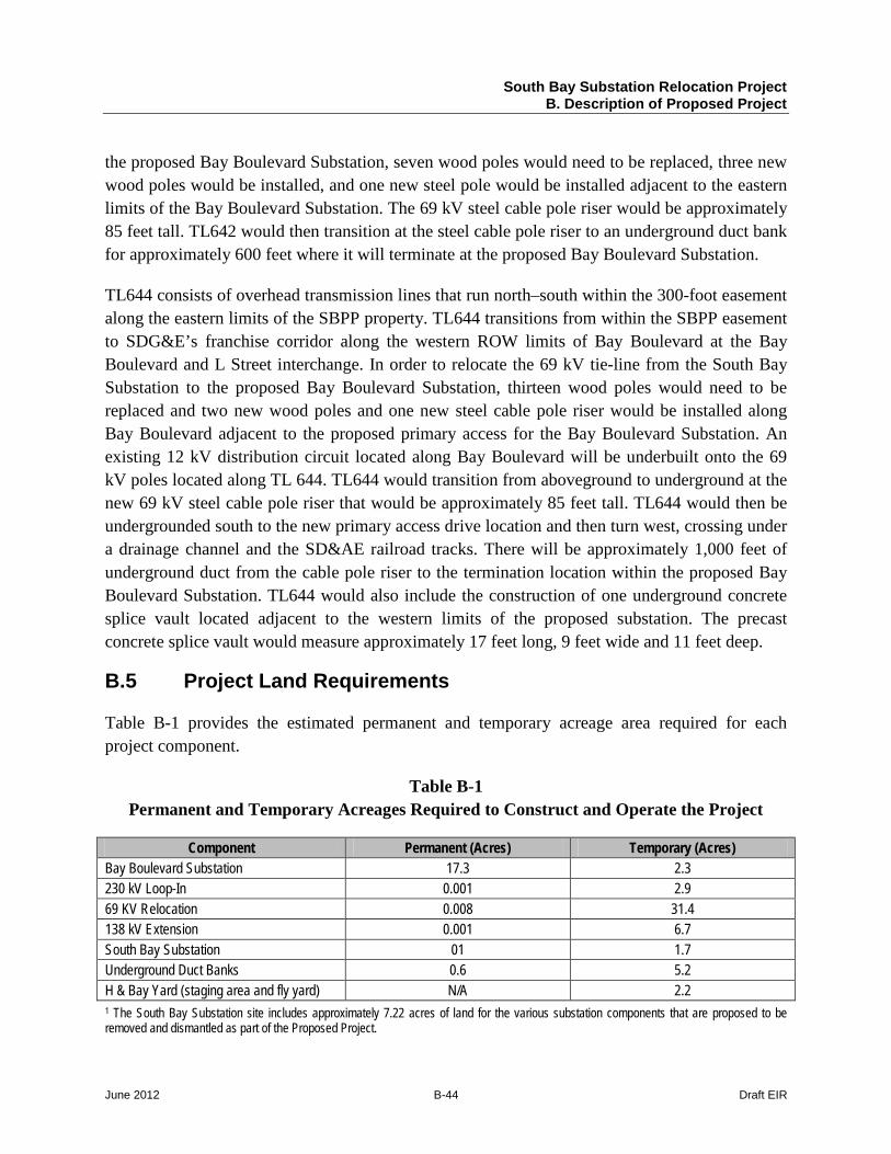
Table B-1 provides the estimated permanent and temporary acreage area required for each project component.
Table B-1 Permanent and Temporary Acreages Required to Construct and Operate the Project
Component Permanent (Acres) Temporary (Acres) Bay Boulevard Substation 17.3 2.3 230 kV Loop-In 0.001 2.9 69 KV Relocation 0.008 31.4 138 kV Extension 0.001 6.7 South Bay Substation 01 1.7 Underground Duct Banks 0.6 5.2 H & Bay Yard (staging area and fly yard) N/A 2.2 1 The South Bay Substation site includes approximately 7.22 acres of land for the various substation components that are proposed to be removed and dismantled as part of the Proposed Project.
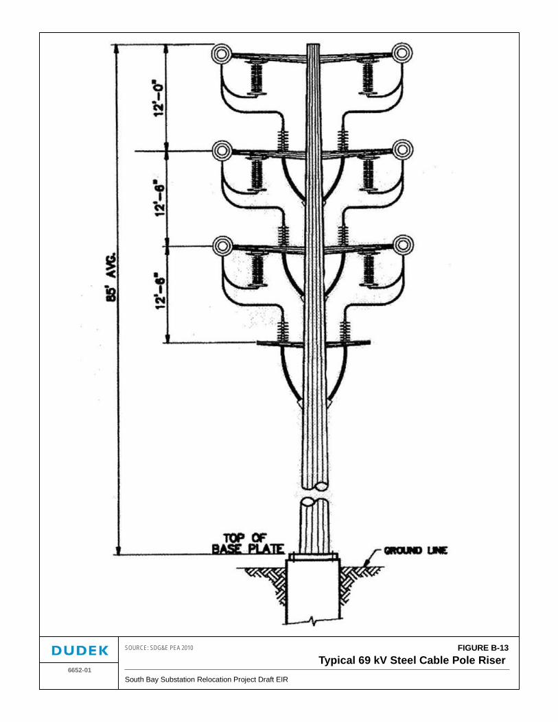
FIGURE B-13Typical 69 kV Steel Cable Pole Riser
6652-01South Bay Substation Relocation Project Draft EIR
SOURCE: SDG&E PEA 2010

South Bay Substation Relocation Project B. Description of Proposed Project
June 2012 B-46 Draft EIR
INTENTIONALLY LEFT BLANK
South Bay Substation Relocation Project B. Description of Proposed Project
June 2012 B-47 Draft EIR
B.6 Construction Activities
This section presents an overview of construction methods typically used for construction of a new substation, demolition of an existing substation, installation of underground and overhead tie-lines, construction of new pole structures, and removal of existing transmission poles. SDG&E’s proposed construction schedule is presented in Section B.6.1, followed by descriptions of construction activities and methods that are anticipated to be required to construct the Proposed Project (Sections B.6.2 through B.6.5). Section B.6.5 provides construction employment, equipment, and materials that would be utilized during construction.
B.6.1 Construction Schedule
The proposed construction will commence after securing all required approvals and permits. The construction of all project components is expected to require approximately 38 months to complete and will require using multiple crews working simultaneously on different project components. Table B-2 provides SDG&E’s proposed schedule for the Proposed Project. While the schedule will be modified to begin after CPUC approval, this table illustrates the approximate length of each construction phase.
Construction activities would generally be limited to no more than 12 hours per 24-hour period (some activities such as transformer oil processing would require continuous work 24 hours per day for 3 to 5 days per transformer), 6 days per week as needed, except during the period when SDG&E needs to perform electrical system transfers. These electrical system transfers would be performed at night to limit the number of customers potentially affected by an unintentional outage. On occasion, nighttime and/or weekend construction activities may also be required in order to minimize impacts on schedules, facilitate cutover work, and as required by other property owners or agencies.
Table B-2 Proposed Schedule
Duration (Months) Project Activity 7 Months Substation Grading and Site Development 7 Months Substation Below Grade Components 10 Months Substation Above Grade Components 11 Months 230 kV Loop-in 7 Months Substation electrical work, commissioning and testing 12 Months 69 kV Relocation and Cutovers 18 Months 138 kV Extension 6 Months Decommission South Bay Substation
Source: SDG&E 2010e Note: Some project activities will be completed simultaneously.
South Bay Substation Relocation Project B. Description of Proposed Project
June 2012 B-48 Draft EIR
This EIR assumes the Proposed Project will be constructed concurrently with the anticipated demolition activities associated with the SBPP. Demolition of the SBPP is anticipated to continue until 2015.
B.6.2 Bay Boulevard Substation
Construction of the Bay Boulevard Substation would be completed within the limits as shown on Figure B-14. An overview of the construction methods, staging areas, and site access is provided below.
Approximately 18.4 acres of vegetation would be removed during the clearing and grading phase. Clearing of vegetation will be completed within the approved work limits.
In order to ensure safe egress/ingress to the site, the existing driveway from Bay Boulevard to the proposed substation site located along the northern limits of the property would be widened and re-graded with compacted Class II aggregate surfacing. This route would ultimately be utilized as the secondary ingress/egress to the site.
The ultimate primary site access located to the south would be constructed concurrently with the installation of the proposed 12 kV and adjacent 69 kV underground duct banks located below the access road. The access road will be approximately 30 feet wide, constructed of asphalt, and would also include 3-foot-wide shoulders along both sides of the roadway.
Site clearing and grubbing is anticipated to generate approximately 7,500 cubic yards (CY) of material for off-site disposal. An estimated 120,000 CY of fill would be required to raise the substation site to the proposed elevation, which ranges from approximately 16 to 21 feet amsl. Additionally, approximately 20,000 CY of imported Class II base material would be used for surfacing of the proposed substation site and access roads.
Substation construction would require approximately 140,000 CY, or an estimated 9,335 haul truckloads, of imported fill for site development. Approximately 27 truck trips per day for approximately 3 to 6 months would be required during site grading. In addition, approximately six additional trips per day are anticipated for delivery of materials and equipment during the remainder of construction activities. Off-site disposal of clear and grub materials would also be required, consisting of approximately 7,500 CY, which includes an estimated 500 truckloads. Table B-3 provides a summary of the Bay Boulevard Substation Grading Requirements. Section B.6.6 includes an expanded discussion regarding construction truck trips.
South Bay Substation Relocation Project B. Description of Proposed Project
June 2012 B-49 Draft EIR
Table B-3 Bay Boulevard Substation Grading Requirements
Import and Export Materials Quantity Off-site Disposal of Clear and Grub Materials 7,500 CY Over Excavation and Recompaction of Existing On-site Soils 94,250 CY Imported Structural Fill 120,000 CY Import Class II 20,000 CY Following site preparation, construction of substation equipment foundations would commence. Prior to completing extraction work associated with the foundations, exploratory excavations to verify precise locations of existing underground facilities would be completed. Following foundation work, substation equipment consisting of the 230 kV bay, 69 kV bay, and the 230 kV control house would be constructed.
Staging areas utilized for the construction of the Bay Boulevard Substation would include the 300-foot-wide easement that runs north–south within the property limits of the former LNG site. Upon completion of site grading, the proposed Bay Boulevard Substation site would be used as a staging area. Access to this site would be provided by an existing driveway from Bay Boulevard, which is proposed as an ultimate secondary access (see Figure B-3a and B-14).
Staging may also be required at the H & Bay Yard, located approximately 1.2 miles north of the proposed substation site, as depicted in Figure B-15. This approximately 280-foot by 310-foot staging area is paved and would be used for the storage of construction materials and equipment. The H & Bay Yard would be enclosed by an approximately six-foot-high chain-link fence and screening material will be placed along the eastern limits adjacent to Bay Boulevard.
B.6.3 South Bay Substation Dismantling
Prior to the dismantling of the South Bay Substation, soil, conduit, control house materials, equipment, and steel structures would be tested to determine whether any environmental hazards, such as oil, polychlorinated biphenyls, lead-based paint, and asbestos are present. SDG&E will be required to abate all hazardous materials identified on site prior to commencement of dismantling activities. Dismantling would include removal of all SDG&E-owned equipment, such as transformers, circuit breakers, regulators, disconnect switches, insulators, overhead and underground cabling, and the control house. All material that is able to be recycled such as steel would be tested and then hauled off site for recycling at an approved facility.
Following the dismantling of all overhead equipment, all below-grade facilities would be removed including direct buried control cables and reinforced concrete foundation pads and piers. The foundations associated with the substation equipment would be removed to a depth of approximately 6 feet below grade. Foundation materials that consist of concrete and steel would
South Bay Substation Relocation Project B. Description of Proposed Project
June 2012 B-50 Draft EIR
be separated in order to recycle the steel at an approved facility and to utilize concrete as crushed aggregate fill material.
Access to the South Bay Substation site for construction activities would be provided via an approximately 2,100-foot-long, two-lane paved road located within the limits of the SBPP property.
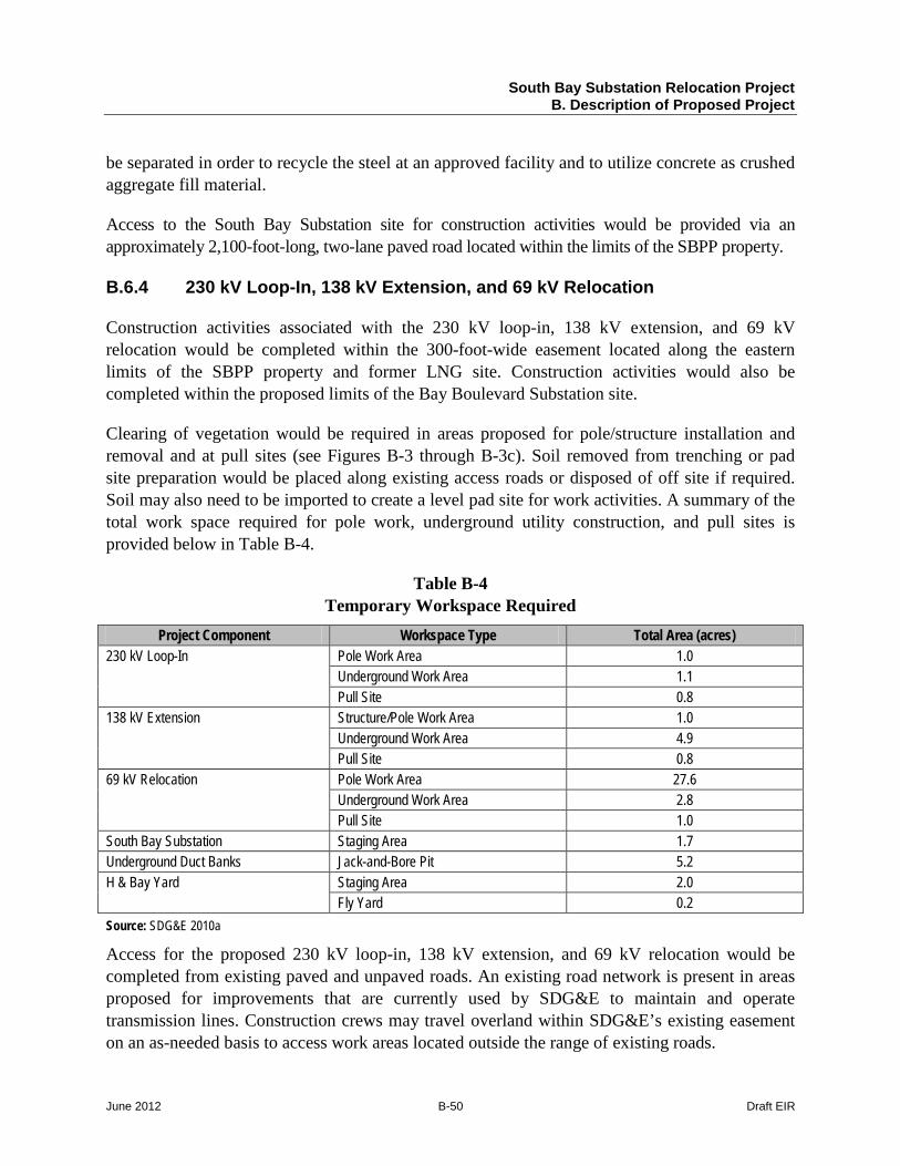
B.6.4 230 kV Loop-In, 138 kV Extension, and 69 kV Relocation
Construction activities associated with the 230 kV loop-in, 138 kV extension, and 69 kV relocation would be completed within the 300-foot-wide easement located along the eastern limits of the SBPP property and former LNG site. Construction activities would also be completed within the proposed limits of the Bay Boulevard Substation site.
Clearing of vegetation would be required in areas proposed for pole/structure installation and removal and at pull sites (see Figures B-3 through B-3c). Soil removed from trenching or pad site preparation would be placed along existing access roads or disposed of off site if required. Soil may also need to be imported to create a level pad site for work activities. A summary of the total work space required for pole work, underground utility construction, and pull sites is provided below in Table B-4.
Table B-4 Temporary Workspace Required
Project Component Workspace Type Total Area (acres) 230 kV Loop-In Pole Work Area 1.0
Underground Work Area 1.1 Pull Site 0.8
138 kV Extension Structure/Pole Work Area 1.0 Underground Work Area 4.9 Pull Site 0.8
69 kV Relocation Pole Work Area 27.6 Underground Work Area 2.8 Pull Site 1.0
South Bay Substation Staging Area 1.7 Underground Duct Banks Jack-and-Bore Pit 5.2 H & Bay Yard Staging Area 2.0
Fly Yard 0.2 Source: SDG&E 2010a
Access for the proposed 230 kV loop-in, 138 kV extension, and 69 kV relocation would be completed from existing paved and unpaved roads. An existing road network is present in areas proposed for improvements that are currently used by SDG&E to maintain and operate transmission lines. Construction crews may travel overland within SDG&E’s existing easement on an as-needed basis to access work areas located outside the range of existing roads.
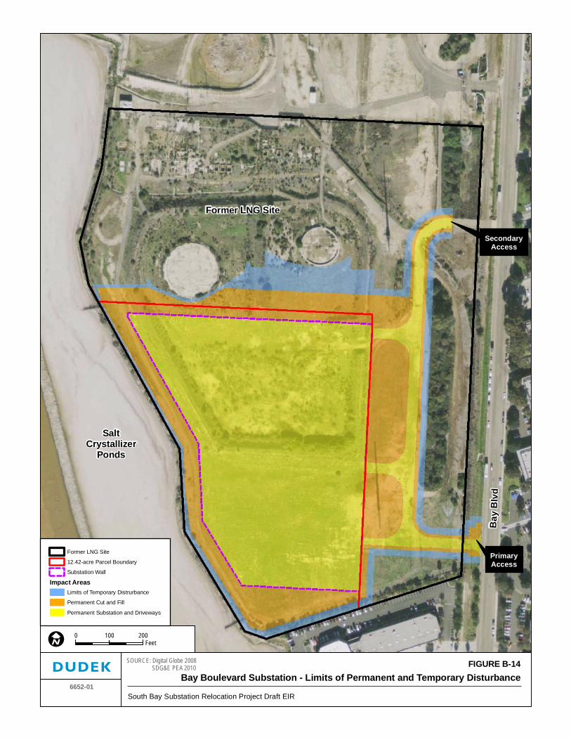
SaltCrystallizer
Ponds
Former LNG Site
Bay
Blv
d
PrimaryAccess
SecondaryAccess
FIGURE B-14Bay Boulevard Substation - Limits of Permanent and Temporary Disturbance
6652-01South Bay Substation Relocation Project Draft EIR
SOURCE: Digital Globe 2008 SDG&E PEA 2010
0 200100Feet
Former LNG Site
12.42-acre Parcel Boundary
Substation Wall
Impact AreasLimits of Temporary Distrurbance
Permanent Cut and Fill
Permanent Substation and Driveways

South Bay Substation Relocation Project B. Description of Proposed Project
June 2012 B-52 Draft EIR
INTENTIONALLY LEFT BLANK
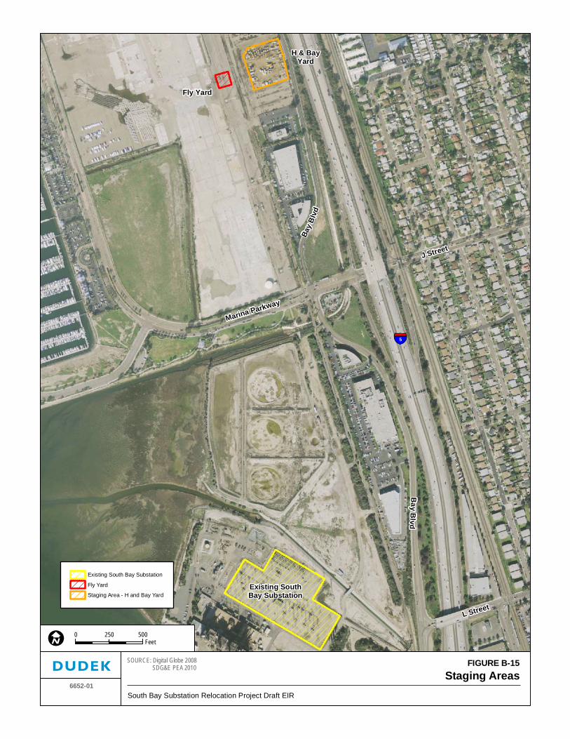
Existing SouthBay Substation
Bay B
lvd
Fly Yard
H & BayYard
Marina Parkway
J Street
L Street
Bay
Blv
d
5
FIGURE B-15Staging Areas
6652-01South Bay Substation Relocation Project Draft EIR
SOURCE: Digital Globe 2008 SDG&E PEA 2010
0 500250Feet
Existing South Bay Substation
Fly Yard
Staging Area - H and Bay Yard

South Bay Substation Relocation Project B. Description of Proposed Project
June 2012 B-54 Draft EIR
INTENTIONALLY LEFT BLANK
South Bay Substation Relocation Project B. Description of Proposed Project
June 2012 B-55 Draft EIR
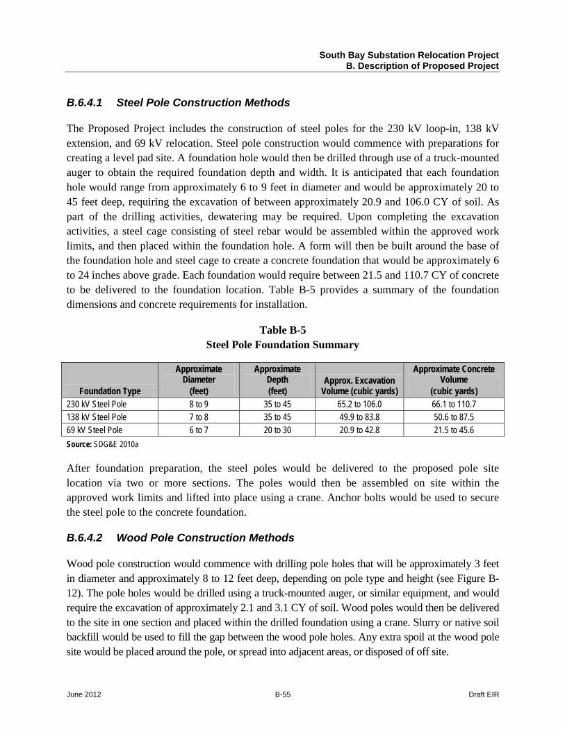
B.6.4.1 Steel Pole Construction Methods
The Proposed Project includes the construction of steel poles for the 230 kV loop-in, 138 kV extension, and 69 kV relocation. Steel pole construction would commence with preparations for creating a level pad site. A foundation hole would then be drilled through use of a truck-mounted auger to obtain the required foundation depth and width. It is anticipated that each foundation hole would range from approximately 6 to 9 feet in diameter and would be approximately 20 to 45 feet deep, requiring the excavation of between approximately 20.9 and 106.0 CY of soil. As part of the drilling activities, dewatering may be required. Upon completing the excavation activities, a steel cage consisting of steel rebar would be assembled within the approved work limits, and then placed within the foundation hole. A form will then be built around the base of the foundation hole and steel cage to create a concrete foundation that would be approximately 6 to 24 inches above grade. Each foundation would require between 21.5 and 110.7 CY of concrete to be delivered to the foundation location. Table B-5 provides a summary of the foundation dimensions and concrete requirements for installation.
Table B-5 Steel Pole Foundation Summary
Foundation Type
Approximate Diameter
(feet)
Approximate Depth (feet)
Approx. Excavation Volume (cubic yards)
Approximate Concrete Volume
(cubic yards) 230 kV Steel Pole 8 to 9 35 to 45 65.2 to 106.0 66.1 to 110.7 138 kV Steel Pole 7 to 8 35 to 45 49.9 to 83.8 50.6 to 87.5 69 kV Steel Pole 6 to 7 20 to 30 20.9 to 42.8 21.5 to 45.6 Source: SDG&E 2010a
After foundation preparation, the steel poles would be delivered to the proposed pole site location via two or more sections. The poles would then be assembled on site within the approved work limits and lifted into place using a crane. Anchor bolts would be used to secure the steel pole to the concrete foundation.
B.6.4.2 Wood Pole Construction Methods
Wood pole construction would commence with drilling pole holes that will be approximately 3 feet in diameter and approximately 8 to 12 feet deep, depending on pole type and height (see Figure B-12). The pole holes would be drilled using a truck-mounted auger, or similar equipment, and would require the excavation of approximately 2.1 and 3.1 CY of soil. Wood poles would then be delivered to the site in one section and placed within the drilled foundation using a crane. Slurry or native soil backfill would be used to fill the gap between the wood pole holes. Any extra spoil at the wood pole site would be placed around the pole, or spread into adjacent areas, or disposed of off site.
South Bay Substation Relocation Project B. Description of Proposed Project
June 2012 B-56 Draft EIR
A typical temporary guard structure
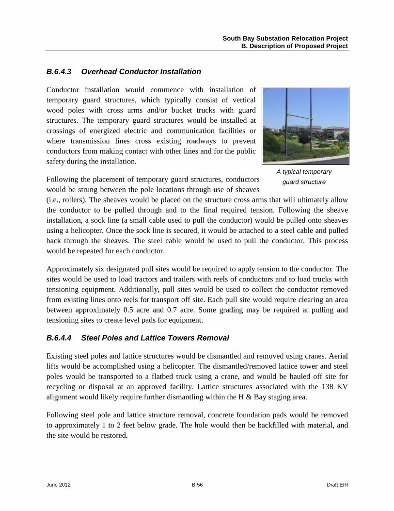
B.6.4.3 Overhead Conductor Installation
Conductor installation would commence with installation of temporary guard structures, which typically consist of vertical wood poles with cross arms and/or bucket trucks with guard structures. The temporary guard structures would be installed at crossings of energized electric and communication facilities or where transmission lines cross existing roadways to prevent conductors from making contact with other lines and for the public safety during the installation.
Following the placement of temporary guard structures, conductors would be strung between the pole locations through use of sheaves (i.e., rollers). The sheaves would be placed on the structure cross arms that will ultimately allow the conductor to be pulled through and to the final required tension. Following the sheave installation, a sock line (a small cable used to pull the conductor) would be pulled onto sheaves using a helicopter. Once the sock line is secured, it would be attached to a steel cable and pulled back through the sheaves. The steel cable would be used to pull the conductor. This process would be repeated for each conductor.
Approximately six designated pull sites would be required to apply tension to the conductor. The sites would be used to load tractors and trailers with reels of conductors and to load trucks with tensioning equipment. Additionally, pull sites would be used to collect the conductor removed from existing lines onto reels for transport off site. Each pull site would require clearing an area between approximately 0.5 acre and 0.7 acre. Some grading may be required at pulling and tensioning sites to create level pads for equipment.
B.6.4.4 Steel Poles and Lattice Towers Removal
Existing steel poles and lattice structures would be dismantled and removed using cranes. Aerial lifts would be accomplished using a helicopter. The dismantled/removed lattice tower and steel poles would be transported to a flatbed truck using a crane, and would be hauled off site for recycling or disposal at an approved facility. Lattice structures associated with the 138 KV alignment would likely require further dismantling within the H & Bay staging area.
Following steel pole and lattice structure removal, concrete foundation pads would be removed to approximately 1 to 2 feet below grade. The hole would then be backfilled with material, and the site would be restored.
South Bay Substation Relocation Project B. Description of Proposed Project
June 2012 B-57 Draft EIR
Underground duct bank construction
B.6.4.5 Wood Pole Removal
Wood pole removal would include dismantling hardware on the existing poles and using a crane or helicopter to remove the wood poles. Poles would be cut off at the ground level and transported for disposal off site. Pole bases would be abandoned in place if removal is not feasible. If the pole base is removed, the pole hole would be backfilled with soil.
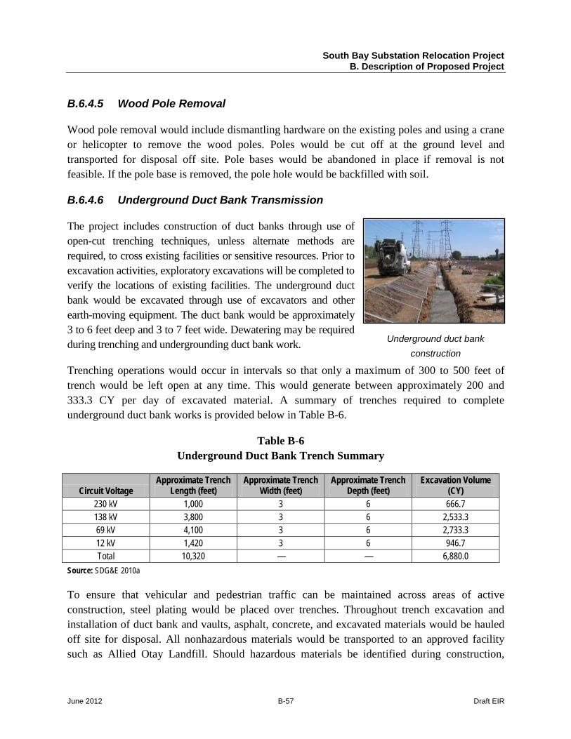
B.6.4.6 Underground Duct Bank Transmission
The project includes construction of duct banks through use of open-cut trenching techniques, unless alternate methods are required, to cross existing facilities or sensitive resources. Prior to excavation activities, exploratory excavations will be completed to verify the locations of existing facilities. The underground duct bank would be excavated through use of excavators and other earth-moving equipment. The duct bank would be approximately 3 to 6 feet deep and 3 to 7 feet wide. Dewatering may be required during trenching and undergrounding duct bank work.
Trenching operations would occur in intervals so that only a maximum of 300 to 500 feet of trench would be left open at any time. This would generate between approximately 200 and 333.3 CY per day of excavated material. A summary of trenches required to complete underground duct bank works is provided below in Table B-6.
Table B-6 Underground Duct Bank Trench Summary
Circuit Voltage Approximate Trench
Length (feet) Approximate Trench
Width (feet) Approximate Trench
Depth (feet) Excavation Volume
(CY) 230 kV 1,000 3 6 666.7 138 kV 3,800 3 6 2,533.3 69 kV 4,100 3 6 2,733.3 12 kV 1,420 3 6 946.7 Total 10,320 — — 6,880.0
Source: SDG&E 2010a
To ensure that vehicular and pedestrian traffic can be maintained across areas of active construction, steel plating would be placed over trenches. Throughout trench excavation and installation of duct bank and vaults, asphalt, concrete, and excavated materials would be hauled off site for disposal. All nonhazardous materials would be transported to an approved facility such as Allied Otay Landfill. Should hazardous materials be identified during construction,
South Bay Substation Relocation Project B. Description of Proposed Project
June 2012 B-58 Draft EIR
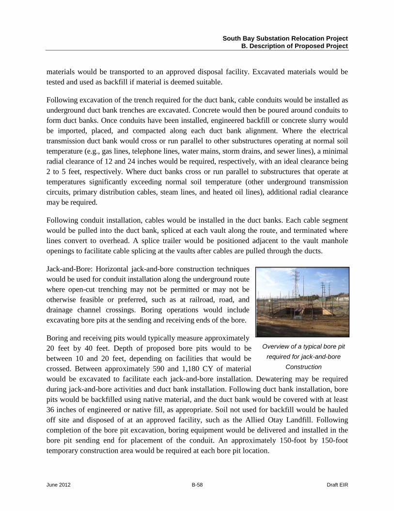
Overview of a typical bore pit required for jack-and-bore
Construction
materials would be transported to an approved disposal facility. Excavated materials would be tested and used as backfill if material is deemed suitable.
Following excavation of the trench required for the duct bank, cable conduits would be installed as underground duct bank trenches are excavated. Concrete would then be poured around conduits to form duct banks. Once conduits have been installed, engineered backfill or concrete slurry would be imported, placed, and compacted along each duct bank alignment. Where the electrical transmission duct bank would cross or run parallel to other substructures operating at normal soil temperature (e.g., gas lines, telephone lines, water mains, storm drains, and sewer lines), a minimal radial clearance of 12 and 24 inches would be required, respectively, with an ideal clearance being 2 to 5 feet, respectively. Where duct banks cross or run parallel to substructures that operate at temperatures significantly exceeding normal soil temperature (other underground transmission circuits, primary distribution cables, steam lines, and heated oil lines), additional radial clearance may be required.
Following conduit installation, cables would be installed in the duct banks. Each cable segment would be pulled into the duct bank, spliced at each vault along the route, and terminated where lines convert to overhead. A splice trailer would be positioned adjacent to the vault manhole openings to facilitate cable splicing at the vaults after cables are pulled through the ducts.
Jack-and-Bore: Horizontal jack-and-bore construction techniques would be used for conduit installation along the underground route where open-cut trenching may not be permitted or may not be otherwise feasible or preferred, such as at railroad, road, and drainage channel crossings. Boring operations would include excavating bore pits at the sending and receiving ends of the bore.
Boring and receiving pits would typically measure approximately 20 feet by 40 feet. Depth of proposed bore pits would to be between 10 and 20 feet, depending on facilities that would be crossed. Between approximately 590 and 1,180 CY of material would be excavated to facilitate each jack-and-bore installation. Dewatering may be required during jack-and-bore activities and duct bank installation. Following duct bank installation, bore pits would be backfilled using native material, and the duct bank would be covered with at least 36 inches of engineered or native fill, as appropriate. Soil not used for backfill would be hauled off site and disposed of at an approved facility, such as the Allied Otay Landfill. Following completion of the bore pit excavation, boring equipment would be delivered and installed in the bore pit sending end for placement of the conduit. An approximately 150-foot by 150-foot temporary construction area would be required at each bore pit location.
South Bay Substation Relocation Project B. Description of Proposed Project
June 2012 B-59 Draft EIR
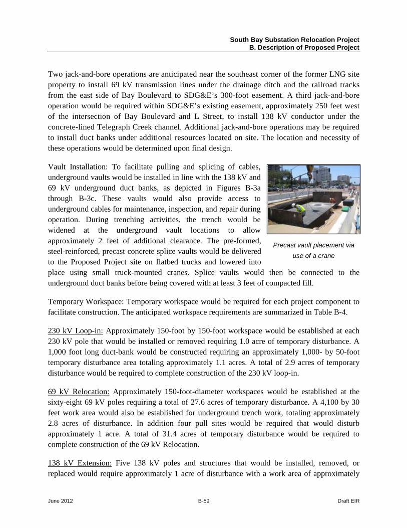
Precast vault placement via use of a crane
Two jack-and-bore operations are anticipated near the southeast corner of the former LNG site property to install 69 kV transmission lines under the drainage ditch and the railroad tracks from the east side of Bay Boulevard to SDG&E’s 300-foot easement. A third jack-and-bore operation would be required within SDG&E’s existing easement, approximately 250 feet west of the intersection of Bay Boulevard and L Street, to install 138 kV conductor under the concrete-lined Telegraph Creek channel. Additional jack-and-bore operations may be required to install duct banks under additional resources located on site. The location and necessity of these operations would be determined upon final design.
Vault Installation: To facilitate pulling and splicing of cables, underground vaults would be installed in line with the 138 kV and 69 kV underground duct banks, as depicted in Figures B-3a through B-3c. These vaults would also provide access to underground cables for maintenance, inspection, and repair during operation. During trenching activities, the trench would be widened at the underground vault locations to allow approximately 2 feet of additional clearance. The pre-formed, steel-reinforced, precast concrete splice vaults would be delivered to the Proposed Project site on flatbed trucks and lowered into place using small truck-mounted cranes. Splice vaults would then be connected to the underground duct banks before being covered with at least 3 feet of compacted fill.
Temporary Workspace: Temporary workspace would be required for each project component to facilitate construction. The anticipated workspace requirements are summarized in Table B-4.
230 kV Loop-in: Approximately 150-foot by 150-foot workspace would be established at each 230 kV pole that would be installed or removed requiring 1.0 acre of temporary disturbance. A 1,000 foot long duct-bank would be constructed requiring an approximately 1,000- by 50-foot temporary disturbance area totaling approximately 1.1 acres. A total of 2.9 acres of temporary disturbance would be required to complete construction of the 230 kV loop-in.
69 kV Relocation: Approximately 150-foot-diameter workspaces would be established at the sixty-eight 69 kV poles requiring a total of 27.6 acres of temporary disturbance. A 4,100 by 30 feet work area would also be established for underground trench work, totaling approximately 2.8 acres of disturbance. In addition four pull sites would be required that would disturb approximately 1 acre. A total of 31.4 acres of temporary disturbance would be required to complete construction of the 69 kV Relocation.
138 kV Extension: Five 138 kV poles and structures that would be installed, removed, or replaced would require approximately 1 acre of disturbance with a work area of approximately
South Bay Substation Relocation Project B. Description of Proposed Project
June 2012 B-60 Draft EIR
150-foot diameter. A 4,300- by 50-foot work area would also be established for underground trench work, totaling approximately 4.9 acres of disturbance. In addition one pull site would be required that would disturb approximately 0.8 acre. A total of 6.7 acres of temporary disturbance would be required to complete construction of the 138 kV Extension.
Jack-and-Bore: Five jack-and-bore locations have been identified to complete construction activities. The jack-and-bore construction methods require both an entry pit and receiving pit that requires a total of 22,500 square feet of temporary working space at each bore pit construction area. A total of approximately 5.2 acres would be required for temporary disturbance associated with all jack-and-bore construction.
Site Restoration/Cleanup
Following completion of construction activities, all disturbed areas would be restored to preconstruction conditions with the exception of areas surrounding poles that would need to be kept clear of shrubs and other obstructions for inspection and maintenance purposes.
B.6.5 Truck Trips, Construction Equipment, and Personnel
Truck trips required for construction of individual project components are shown in Table B-7. Truck trips for construction of the proposed Bay Boulevard Substation would consist of four types of trips, including material delivery, import and export of material during site development, import and export of material during duct bank installation, and delivery of asphalt during paving. Approximately six trips per day would be required during the anticipated 472-day-long construction period for substation material delivery. Site development activities at the proposed Bay Boulevard Substation would require approximately 9,335 truck trips. An additional 313 truck trips at a rate of approximately one per day would also be required to allow for the import and export of material during underground duct bank installation. Asphalt delivery to the proposed substation would require approximately 40 trips to pave the access roads and driveways.
The demolition of the existing South Bay Substation is assumed to require approximately six truck trips per day throughout the approximately 209-day-long demolition period. As a result, approximately 1,254 trips would be required to complete demolition of the South Bay Substation.
Truck trips for the construction of the 230 kV loop-in, 69 kV relocation, and 138 kV extension would be approximately 545 trips, which includes the import and export of materials.
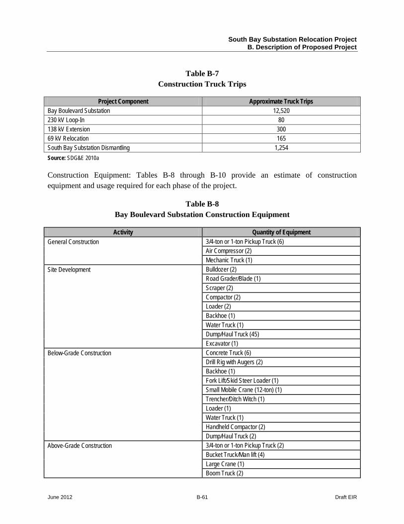
South Bay Substation Relocation Project B. Description of Proposed Project
June 2012 B-61 Draft EIR
Table B-7 Construction Truck Trips
Project Component Approximate Truck Trips Bay Boulevard Substation 12,520 230 kV Loop-In 80 138 kV Extension 300 69 kV Relocation 165 South Bay Substation Dismantling 1,254 Source: SDG&E 2010a
Construction Equipment: Tables B-8 through B-10 provide an estimate of construction equipment and usage required for each phase of the project.
Table B-8 Bay Boulevard Substation Construction Equipment
Activity Quantity of Equipment General Construction 3/4-ton or 1-ton Pickup Truck (6)
Air Compressor (2) Mechanic Truck (1)
Site Development Bulldozer (2) Road Grader/Blade (1) Scraper (2) Compactor (2) Loader (2) Backhoe (1) Water Truck (1) Dump/Haul Truck (45) Excavator (1)
Below-Grade Construction Concrete Truck (6) Drill Rig with Augers (2) Backhoe (1) Fork Lift/Skid Steer Loader (1) Small Mobile Crane (12-ton) (1) Trencher/Ditch Witch (1) Loader (1) Water Truck (1) Handheld Compactor (2) Dump/Haul Truck (2)
Above-Grade Construction 3/4-ton or 1-ton Pickup Truck (2) Bucket Truck/Man lift (4) Large Crane (1) Boom Truck (2)
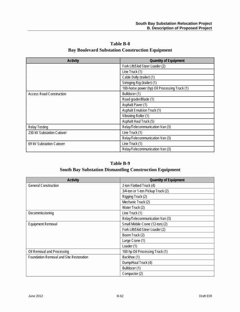
South Bay Substation Relocation Project B. Description of Proposed Project
June 2012 B-62 Draft EIR
Table B-8 Bay Boulevard Substation Construction Equipment
Activity Quantity of Equipment Fork Lift/Skid Steer Loader (2) Line Truck (1) Cable Dolly (trailer) (1) Stringing Rig (trailer) (1) 100-horse power (hp) Oil Processing Truck (1)
Access Road Construction Bulldozer (1) Road grader/Blade (1) Asphalt Paver (1) Asphalt Emulsion Truck (1) Vibrating Roller (1) Asphalt Haul Truck (5)
Relay Testing Relay/Telecommunication Van (3) 230 kV Substation Cutover Line Truck (1)
Relay/Telecommunication Van (3) 69 kV Substation Cutover Line Truck (1)
Relay/Telecommunication Van (3)
Table B-9 South Bay Substation Dismantling Construction Equipment
Activity Quantity of Equipment General Construction 2-ton Flatbed Truck (4)
3/4-ton or 1-ton Pickup Truck (2) Rigging Truck (2) Mechanic Truck (2) Water Truck (2)
Decommissioning Line Truck (1) Relay/Telecommunication Van (3)
Equipment Removal Small Mobile Crane (12-ton) (2) Fork Lift/Skid Steer Loader (2) Boom Truck (2) Large Crane (1) Loader (1)
Oil Removal and Processing 100 hp Oil Processing Truck (1) Foundation Removal and Site Restoration Backhoe (1)
Dump/Haul Truck (4) Bulldozer (1) Compactor (2)
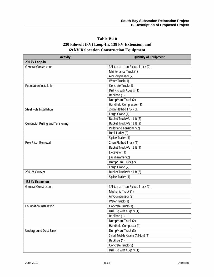
South Bay Substation Relocation Project B. Description of Proposed Project
June 2012 B-63 Draft EIR
Table B-10 230 kilovolt (kV) Loop-In, 138 kV Extension, and
69 kV Relocation Construction Equipment
Activity Quantity of Equipment 230 kV Loop-in General Construction 3/4-ton or 1-ton Pickup Truck (2)
Maintenance Truck (1) Air Compressor (2) Water Truck (1)
Foundation Installation Concrete Truck (1) Drill Rig with Augers (1) Backhoe (1) Dump/Haul Truck (2) Handheld Compressor (1)
Steel Pole Installation 2-ton Flatbed Truck (1) Large Crane (1) Bucket Truck/Man Lift (2)
Conductor Pulling and Tensioning Bucket Truck/Man Lift (2) Puller and Tensioner (2) Reel Trailer (2) Splice Trailer (1)
Pole Riser Removal 2-ton Flatbed Truck (1) Bucket Truck/Man Lift (1) Excavator (1) Jackhammer (2) Dump/Haul Truck (2) Large Crane (2)
230 kV Cutover Bucket Truck/Man Lift (2) Splice Trailer (1)
138 kV Extension General Construction 3/4-ton or 1-ton Pickup Truck (2)
Mechanic Truck (1) Air Compressor (2) Water Truck (1)
Foundation Installation Concrete Truck (1) Drill Rig with Augers (1) Backhoe (1) Dump/Haul Truck (2) Handheld Compactor (1)
Underground Duct Bank Dump/Haul Truck (3) Small Mobile Crane (12-ton) (1) Backhoe (1) Concrete Truck (5) Drill Rig with Augers (1)
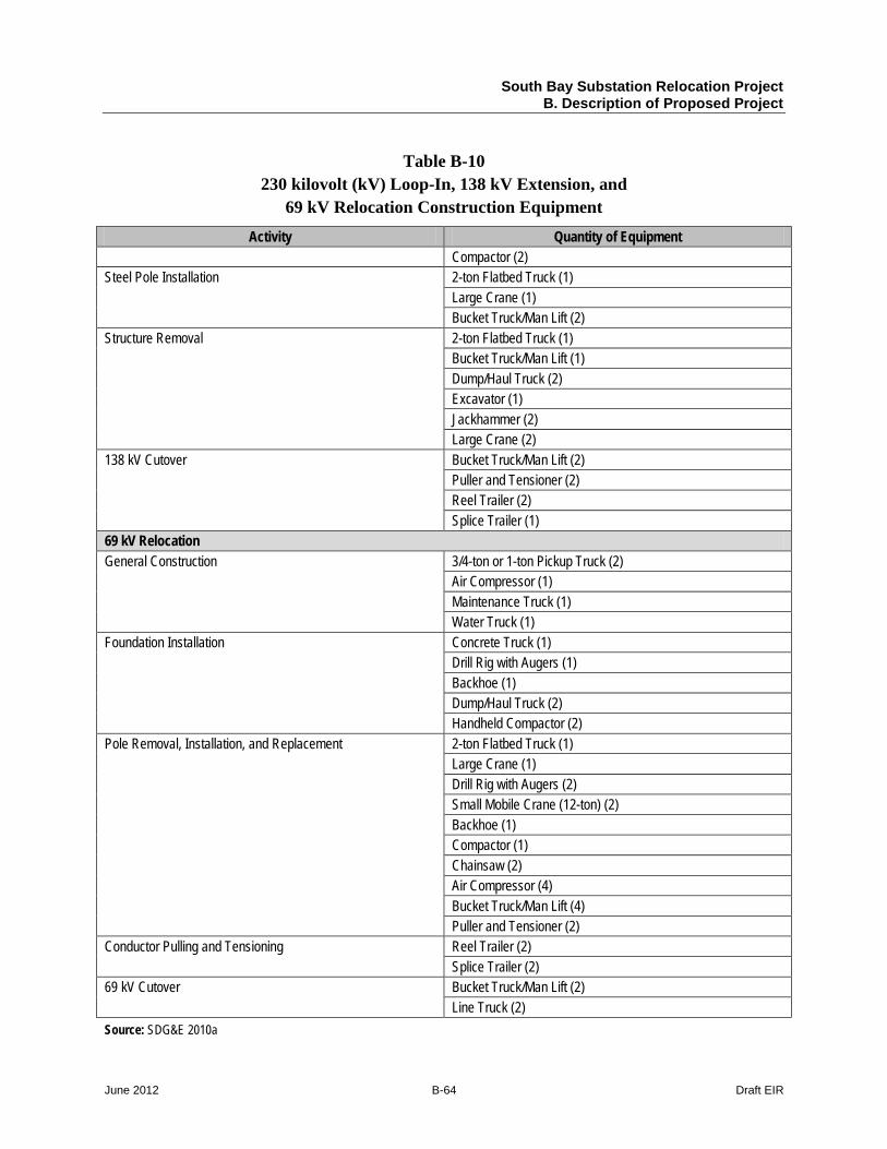
South Bay Substation Relocation Project B. Description of Proposed Project
June 2012 B-64 Draft EIR
Table B-10 230 kilovolt (kV) Loop-In, 138 kV Extension, and
69 kV Relocation Construction Equipment
Activity Quantity of Equipment Compactor (2)
Steel Pole Installation 2-ton Flatbed Truck (1) Large Crane (1) Bucket Truck/Man Lift (2)
Structure Removal 2-ton Flatbed Truck (1) Bucket Truck/Man Lift (1) Dump/Haul Truck (2) Excavator (1) Jackhammer (2) Large Crane (2)
138 kV Cutover Bucket Truck/Man Lift (2) Puller and Tensioner (2) Reel Trailer (2) Splice Trailer (1)
69 kV Relocation General Construction 3/4-ton or 1-ton Pickup Truck (2)
Air Compressor (1) Maintenance Truck (1) Water Truck (1)
Foundation Installation Concrete Truck (1) Drill Rig with Augers (1) Backhoe (1) Dump/Haul Truck (2) Handheld Compactor (2)
Pole Removal, Installation, and Replacement 2-ton Flatbed Truck (1) Large Crane (1) Drill Rig with Augers (2) Small Mobile Crane (12-ton) (2) Backhoe (1) Compactor (1) Chainsaw (2) Air Compressor (4) Bucket Truck/Man Lift (4) Puller and Tensioner (2)
Conductor Pulling and Tensioning Reel Trailer (2) Splice Trailer (2)
69 kV Cutover Bucket Truck/Man Lift (2) Line Truck (2)
Source: SDG&E 2010a
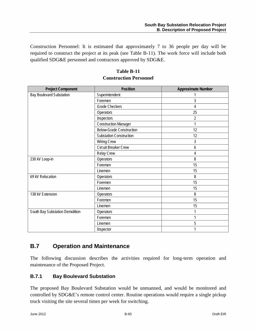
South Bay Substation Relocation Project B. Description of Proposed Project
June 2012 B-65 Draft EIR
Construction Personnel: It is estimated that approximately 7 to 36 people per day will be required to construct the project at its peak (see Table B-11). The work force will include both qualified SDG&E personnel and contractors approved by SDG&E.
Table B-11 Construction Personnel
Project Component Position Approximate Number Bay Boulevard Substation Superintendent 1
Foremen 3 Grade Checkers 4 Operators 25 Inspectors 2 Construction Manager 1 Below-Grade Construction 12 Substation Construction 12 Wiring Crew 3 Circuit Breaker Crew 6 Relay Crew 4
230 kV Loop-in Operators 8 Foremen 15 Linemen 15
69 kV Relocation Operators 8 Foremen 15 Linemen 15
138 kV Extension Operators 8 Foremen 15 Linemen 15
South Bay Substation Demolition Operators 1 Foremen 1 Linemen 5 Inspector 1
B.7 Operation and Maintenance
The following discussion describes the activities required for long-term operation and maintenance of the Proposed Project.
B.7.1 Bay Boulevard Substation
The proposed Bay Boulevard Substation would be unmanned, and would be monitored and controlled by SDG&E’s remote control center. Routine operations would require a single pickup truck visiting the site several times per week for switching.
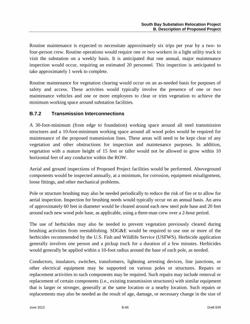
South Bay Substation Relocation Project B. Description of Proposed Project
June 2012 B-66 Draft EIR
Routine maintenance is expected to necessitate approximately six trips per year by a two- to four-person crew. Routine operations would require one or two workers in a light utility truck to visit the substation on a weekly basis. It is anticipated that one annual, major maintenance inspection would occur, requiring an estimated 20 personnel. This inspection is anticipated to take approximately 1 week to complete.
Routine maintenance for vegetation clearing would occur on an as-needed basis for purposes of safety and access. These activities would typically involve the presence of one or two maintenance vehicles and one or more employees to clear or trim vegetation to achieve the minimum working space around substation facilities.
B.7.2 Transmission Interconnections
A 30-foot-minimum (from edge to foundation) working space around all steel transmission structures and a 10-foot-minimum working space around all wood poles would be required for maintenance of the proposed transmission lines. These areas will need to be kept clear of any vegetation and other obstructions for inspection and maintenance purposes. In addition, vegetation with a mature height of 15 feet or taller would not be allowed to grow within 10 horizontal feet of any conductor within the ROW.
Aerial and ground inspections of Proposed Project facilities would be performed. Aboveground components would be inspected annually, at a minimum, for corrosion, equipment misalignment, loose fittings, and other mechanical problems.
Pole or structure brushing may also be needed periodically to reduce the risk of fire or to allow for aerial inspection. Inspection for brushing needs would typically occur on an annual basis. An area of approximately 60 feet in diameter would be cleared around each new steel pole base and 20 feet around each new wood pole base, as applicable, using a three-man crew over a 2-hour period.
The use of herbicides may also be needed to prevent vegetation previously cleared during brushing activities from reestablishing. SDG&E would be required to use one or more of the herbicides recommended by the U.S. Fish and Wildlife Service (USFWS). Herbicide application generally involves one person and a pickup truck for a duration of a few minutes. Herbicides would generally be applied within a 10-foot radius around the base of each pole, as needed.
Conductors, insulators, switches, transformers, lightning arresting devices, line junctions, or other electrical equipment may be supported on various poles or structures. Repairs or replacement activities to such components may be required. Such repairs may include removal or replacement of certain components (i.e., existing transmission structures) with similar equipment that is larger or stronger, generally at the same location or a nearby location. Such repairs or replacements may also be needed as the result of age, damage, or necessary change in the size of
South Bay Substation Relocation Project B. Description of Proposed Project
June 2012 B-67 Draft EIR
a conductor. Repair or replacement of such equipment would generally require a crew composed of four personnel with two to three trucks (a boom or line truck, an aerial lift truck, and an assist truck) to gain access to the area of the equipment in need of repair or replacement.
SDG&E will also complete routine washing of insulators to avoid the potential for buildup of condensation combined with dust, which can create an electrical discharge. The washing process would require the use of a water truck, typically operated by a two-man crew, which allows a high-pressure hose to be used to spray deionized water on the insulators. Insulator washing generally requires access to the structure base and a working area of approximately 30 by 40 feet. Inspection of the insulators typically occurs on an annual basis to identify the need for washing.
B.8 SDG&E Project Protocols
Section 3.9.1 of the SDG&E June 2010 PEA, prepared by Insignia Environmental, details the project protocols that will be followed during all project-related activities (SDG&E 2010a). Project protocols are specific to environmental issue areas, such as air quality, biological resources, cultural resources, or traffic impacts. SDG&E’s Proposed Project protocols are herein termed Applicant Proposed Measures (APMs). Table B-12 lists which APMs are applicable to each environmental issue area; Table B-13 lists the APMs as proposed in the PEA.
Table B-12 Applicant Proposed Measures for Each Issue Area
Issue Area APMs Aesthetics AES-01 and -02 Air Quality AIR-01, -02, -03, and -04 Biological Resources BIO-01, -02, -03, -04, -05, and -06 Cultural Resources CUL-01, -02, -03, -04, -05, and -06 Geology, Soils, Mineral Resources, Paleontology GEO-01 Hazardous Materials HAZ-01 Traffic TRA-01

South Bay Substation Relocation Project B. Description of Proposed Project
June 2012 B-68 Draft EIR
Table B-13 Applicant Proposed Measures
APM No Description Proposed Project Component
Bay Boulevard Substation
230 kV Loop-In
69 kV Relocation
138 kV Extension
South Bay Substation Demolition
Aesthetics APM-AES-01 Figure B-7, Conceptual Landscape Plan,
presents a conceptual landscape mitigation plan for the Bay Boulevard Substation that would be implemented as part of the Proposed Project. The conceptual landscape plan would provide partial screening of views of the substation site and new utility poles from Bay Boulevard and locations further east. The landscaping would also partially screen views from the office park to the south. Landscaping includes informal tree and shrub groupings outside of the wall, east of the substation. Small native trees would also be used to extend plantings at the southern end of the mound to the east of the facility. Small trees would also line the entry drive. Figure B-7, Conceptual Landscape Plan, includes a list of recommended plant species. All suggested trees appear on the City of San Diego Street Tree Selection Guide. Plants listed in Chapter 12.32 of the City of Chula Vista Municipal Code as prohibited species are excluded. Drought-tolerant plants, including California native species, are suggested. Proposed Project landscaping would receive regular watering during the initial two years following installation in order to ensure the establishment of the plants. As noted on Figure B-7, Conceptual Landscape Concept, landscaping under transmission lines would consist of smaller trees and/or shrubs to allow for overhead clearance. All planting would be consistent with SDG&E operational requirements for landscaping in proximity to electric transmission facilities.
APM-AES-02 The color of the substation perimeter wall would be chosen to blend with the existing site features (i.e., a dull gray, light brown, or dull green) and minimize visual contrast with the bayfront landscape setting.
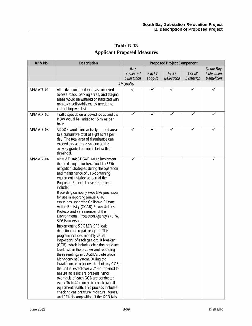
South Bay Substation Relocation Project B. Description of Proposed Project
June 2012 B-69 Draft EIR
Table B-13 Applicant Proposed Measures
APM No Description Proposed Project Component
Bay Boulevard Substation
230 kV Loop-In
69 kV Relocation
138 kV Extension
South Bay Substation Demolition
Air Quality APM-AIR-01 All active construction areas, unpaved
access roads, parking areas, and staging areas would be watered or stabilized with non-toxic soil stabilizers as needed to control fugitive dust.
APM-AIR-02 Traffic speeds on unpaved roads and the ROW would be limited to 15 miles per hour.
APM-AIR-03 SDG&E would limit actively graded areas to a cumulative total of eight acres per day. The total area of disturbance can exceed this acreage so long as the actively graded portion is below this threshold.
APM-AIR-04 APM-AIR-04: SDG&E would implement their existing sulfur hexafluoride (SF6) mitigation strategies during the operation and maintenance of SF6-containing equipment installed as part of the Proposed Project. These strategies include: Recording company-wide SF6 purchases for use in reporting annual GHG emissions under the California Climate Action Registry (CCAR) Power Utilities Protocol and as a member of the Environmental Protection Agency’s (EPA) SF6 Partnership Implementing SDG&E’s SF6 leak detection and repair program. This program includes monthly visual inspections of each gas circuit breaker (GCB), which includes checking pressure levels within the breaker and recording these readings in SDG&E’s Substation Management System. During the installation or major overhaul of any GCB, the unit is tested over a 24-hour period to ensure no leaks are present. Minor overhauls of each GCB are conducted every 36 to 40 months to check overall equipment health. This process includes checking gas pressure, moisture ingress, and SF6 decomposition. If the GCB fails
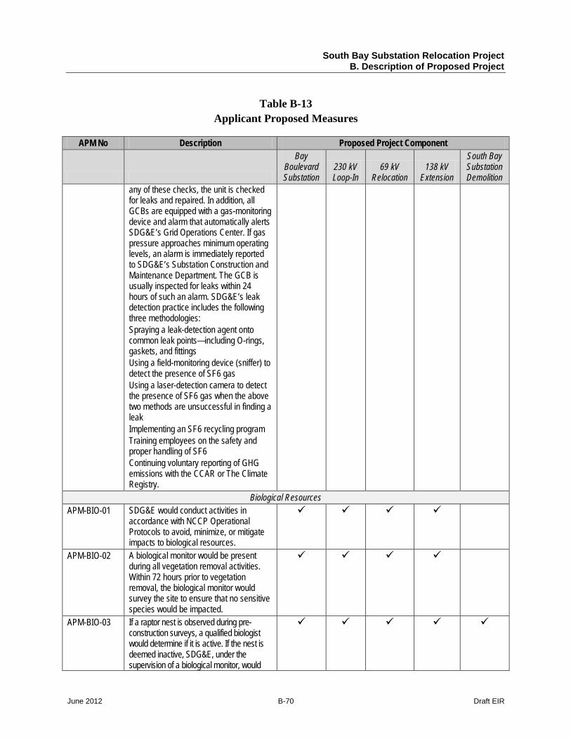
South Bay Substation Relocation Project B. Description of Proposed Project
June 2012 B-70 Draft EIR
Table B-13 Applicant Proposed Measures
APM No Description Proposed Project Component
Bay Boulevard Substation
230 kV Loop-In
69 kV Relocation
138 kV Extension
South Bay Substation Demolition
any of these checks, the unit is checked for leaks and repaired. In addition, all GCBs are equipped with a gas-monitoring device and alarm that automatically alerts SDG&E’s Grid Operations Center. If gas pressure approaches minimum operating levels, an alarm is immediately reported to SDG&E’s Substation Construction and Maintenance Department. The GCB is usually inspected for leaks within 24 hours of such an alarm. SDG&E’s leak detection practice includes the following three methodologies: Spraying a leak-detection agent onto common leak points—including O-rings, gaskets, and fittings Using a field-monitoring device (sniffer) to detect the presence of SF6 gas Using a laser-detection camera to detect the presence of SF6 gas when the above two methods are unsuccessful in finding a leak Implementing an SF6 recycling program Training employees on the safety and proper handling of SF6 Continuing voluntary reporting of GHG emissions with the CCAR or The Climate Registry.
Biological Resources APM-BIO-01 SDG&E would conduct activities in
accordance with NCCP Operational Protocols to avoid, minimize, or mitigate impacts to biological resources.
APM-BIO-02 A biological monitor would be present during all vegetation removal activities. Within 72 hours prior to vegetation removal, the biological monitor would survey the site to ensure that no sensitive species would be impacted.
APM-BIO-03 If a raptor nest is observed during pre-construction surveys, a qualified biologist would determine if it is active. If the nest is deemed inactive, SDG&E, under the supervision of a biological monitor, would
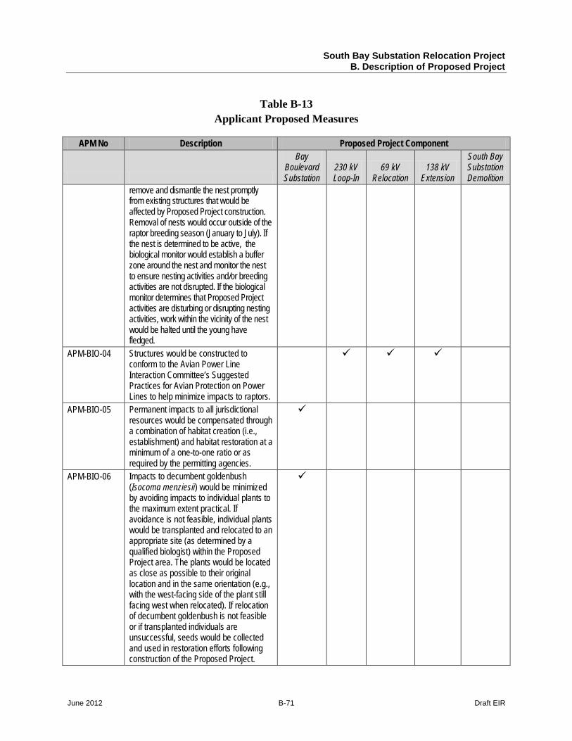
South Bay Substation Relocation Project B. Description of Proposed Project
June 2012 B-71 Draft EIR
Table B-13 Applicant Proposed Measures
APM No Description Proposed Project Component
Bay Boulevard Substation
230 kV Loop-In
69 kV Relocation
138 kV Extension
South Bay Substation Demolition
remove and dismantle the nest promptly from existing structures that would be affected by Proposed Project construction. Removal of nests would occur outside of the raptor breeding season (January to July). If the nest is determined to be active, the biological monitor would establish a buffer zone around the nest and monitor the nest to ensure nesting activities and/or breeding activities are not disrupted. If the biological monitor determines that Proposed Project activities are disturbing or disrupting nesting activities, work within the vicinity of the nest would be halted until the young have fledged.
APM-BIO-04 Structures would be constructed to conform to the Avian Power Line Interaction Committee’s Suggested Practices for Avian Protection on Power Lines to help minimize impacts to raptors.
APM-BIO-05 Permanent impacts to all jurisdictional resources would be compensated through a combination of habitat creation (i.e., establishment) and habitat restoration at a minimum of a one-to-one ratio or as required by the permitting agencies.
APM-BIO-06 Impacts to decumbent goldenbush (Isocoma menziesii) would be minimized by avoiding impacts to individual plants to the maximum extent practical. If avoidance is not feasible, individual plants would be transplanted and relocated to an appropriate site (as determined by a qualified biologist) within the Proposed Project area. The plants would be located as close as possible to their original location and in the same orientation (e.g., with the west-facing side of the plant still facing west when relocated). If relocation of decumbent goldenbush is not feasible or if transplanted individuals are unsuccessful, seeds would be collected and used in restoration efforts following construction of the Proposed Project.
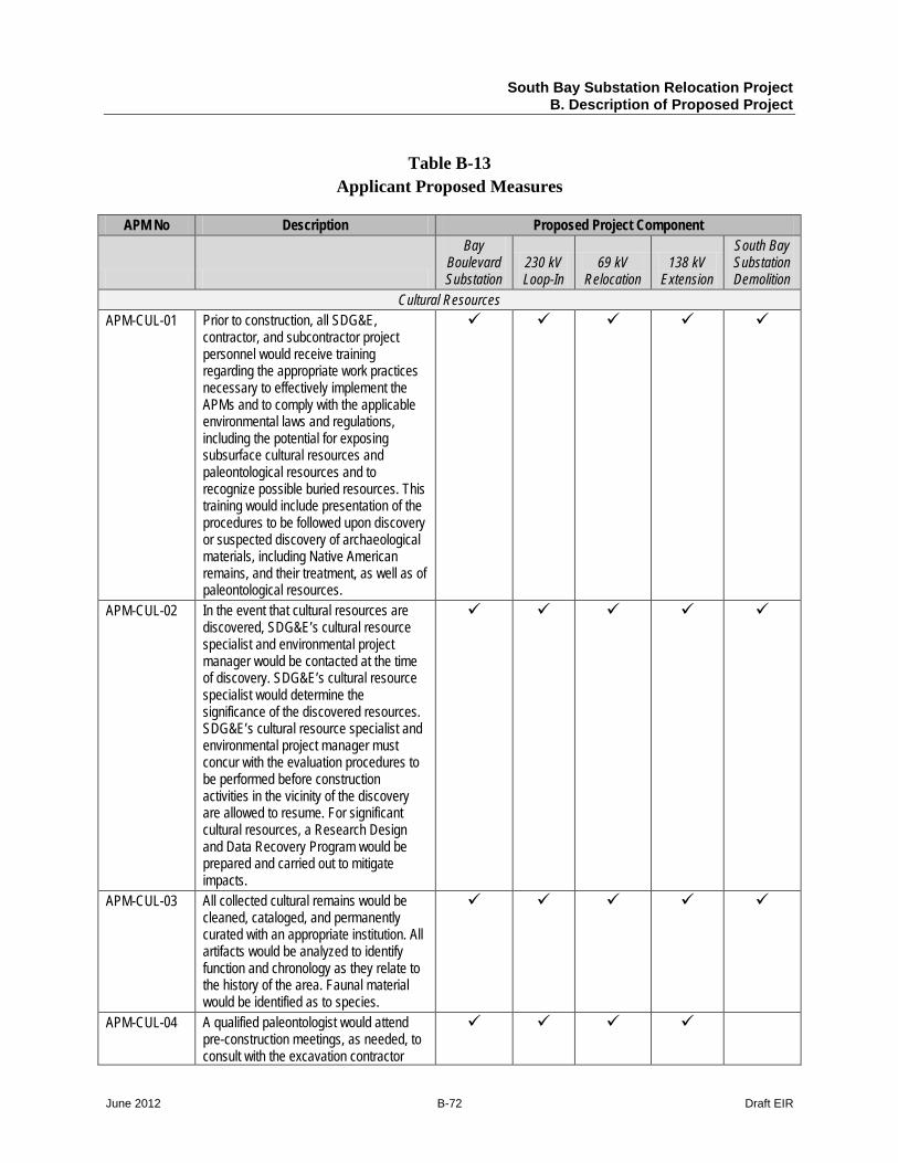
South Bay Substation Relocation Project B. Description of Proposed Project
June 2012 B-72 Draft EIR
Table B-13 Applicant Proposed Measures
APM No Description Proposed Project Component
Bay Boulevard Substation
230 kV Loop-In
69 kV Relocation
138 kV Extension
South Bay Substation Demolition
Cultural Resources APM-CUL-01 Prior to construction, all SDG&E,
contractor, and subcontractor project personnel would receive training regarding the appropriate work practices necessary to effectively implement the APMs and to comply with the applicable environmental laws and regulations, including the potential for exposing subsurface cultural resources and paleontological resources and to recognize possible buried resources. This training would include presentation of the procedures to be followed upon discovery or suspected discovery of archaeological materials, including Native American remains, and their treatment, as well as of paleontological resources.
APM-CUL-02 In the event that cultural resources are discovered, SDG&E’s cultural resource specialist and environmental project manager would be contacted at the time of discovery. SDG&E’s cultural resource specialist would determine the significance of the discovered resources. SDG&E’s cultural resource specialist and environmental project manager must concur with the evaluation procedures to be performed before construction activities in the vicinity of the discovery are allowed to resume. For significant cultural resources, a Research Design and Data Recovery Program would be prepared and carried out to mitigate impacts.
APM-CUL-03 All collected cultural remains would be cleaned, cataloged, and permanently curated with an appropriate institution. All artifacts would be analyzed to identify function and chronology as they relate to the history of the area. Faunal material would be identified as to species.
APM-CUL-04 A qualified paleontologist would attend pre-construction meetings, as needed, to consult with the excavation contractor
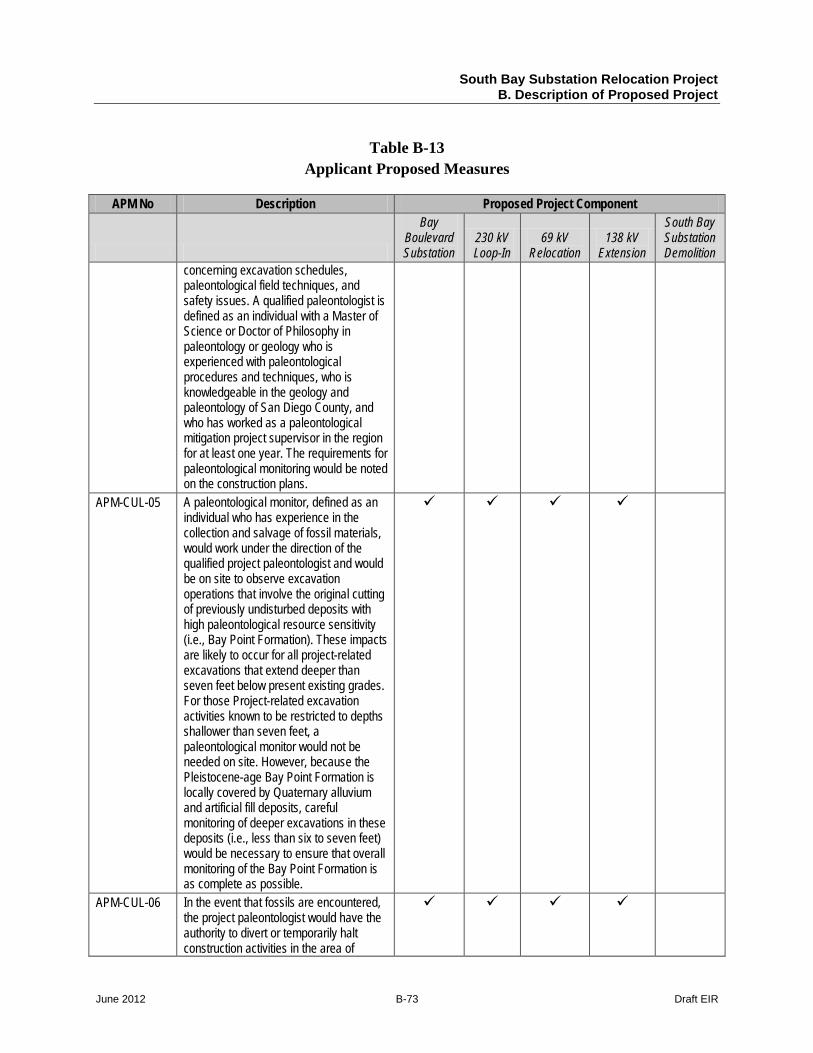
South Bay Substation Relocation Project B. Description of Proposed Project
June 2012 B-73 Draft EIR
Table B-13 Applicant Proposed Measures
APM No Description Proposed Project Component
Bay Boulevard Substation
230 kV Loop-In
69 kV Relocation
138 kV Extension
South Bay Substation Demolition
concerning excavation schedules, paleontological field techniques, and safety issues. A qualified paleontologist is defined as an individual with a Master of Science or Doctor of Philosophy in paleontology or geology who is experienced with paleontological procedures and techniques, who is knowledgeable in the geology and paleontology of San Diego County, and who has worked as a paleontological mitigation project supervisor in the region for at least one year. The requirements for paleontological monitoring would be noted on the construction plans.
APM-CUL-05 A paleontological monitor, defined as an individual who has experience in the collection and salvage of fossil materials, would work under the direction of the qualified project paleontologist and would be on site to observe excavation operations that involve the original cutting of previously undisturbed deposits with high paleontological resource sensitivity (i.e., Bay Point Formation). These impacts are likely to occur for all project-related excavations that extend deeper than seven feet below present existing grades. For those Project-related excavation activities known to be restricted to depths shallower than seven feet, a paleontological monitor would not be needed on site. However, because the Pleistocene-age Bay Point Formation is locally covered by Quaternary alluvium and artificial fill deposits, careful monitoring of deeper excavations in these deposits (i.e., less than six to seven feet) would be necessary to ensure that overall monitoring of the Bay Point Formation is as complete as possible.
APM-CUL-06 In the event that fossils are encountered, the project paleontologist would have the authority to divert or temporarily halt construction activities in the area of
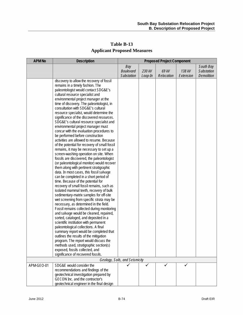
South Bay Substation Relocation Project B. Description of Proposed Project
June 2012 B-74 Draft EIR
Table B-13 Applicant Proposed Measures
APM No Description Proposed Project Component
Bay Boulevard Substation
230 kV Loop-In
69 kV Relocation
138 kV Extension
South Bay Substation Demolition
discovery to allow the recovery of fossil remains in a timely fashion. The paleontologist would contact SDG&E’s cultural resource specialist and environmental project manager at the time of discovery. The paleontologist, in consultation with SDG&E’s cultural resource specialist, would determine the significance of the discovered resources. SDG&E’s cultural resource specialist and environmental project manager must concur with the evaluation procedures to be performed before construction activities are allowed to resume. Because of the potential for recovery of small fossil remains, it may be necessary to set up a screen-washing operation on site. When fossils are discovered, the paleontologist (or paleontological monitor) would recover them along with pertinent stratigraphic data. In most cases, this fossil salvage can be completed in a short period of time. Because of the potential for recovery of small fossil remains, such as isolated mammal teeth, recovery of bulk sedimentary-matrix samples for off-site wet screening from specific strata may be necessary, as determined in the field. Fossil remains collected during monitoring and salvage would be cleaned, repaired, sorted, cataloged, and deposited in a scientific institution with permanent paleontological collections. A final summary report would be completed that outlines the results of the mitigation program. The report would discuss the methods used, stratigraphic section(s) exposed, fossils collected, and significance of recovered fossils.
Geology, Soils, and Seismicity APM-GEO-01 SDG&E would consider the
recommendations and findings of the geotechnical investigation prepared by GECON Inc. and the contractor’s geotechnical engineer in the final design
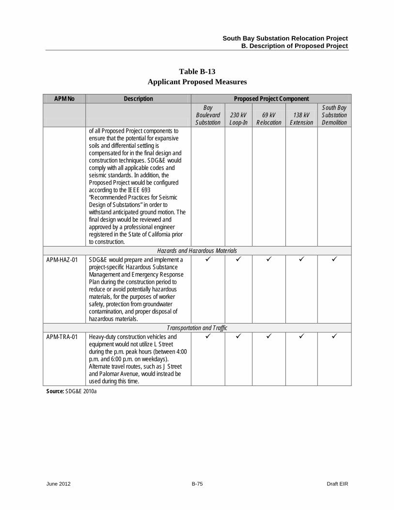
South Bay Substation Relocation Project B. Description of Proposed Project
June 2012 B-75 Draft EIR
Table B-13 Applicant Proposed Measures
APM No Description Proposed Project Component
Bay Boulevard Substation
230 kV Loop-In
69 kV Relocation
138 kV Extension
South Bay Substation Demolition
of all Proposed Project components to ensure that the potential for expansive soils and differential settling is compensated for in the final design and construction techniques. SDG&E would comply with all applicable codes and seismic standards. In addition, the Proposed Project would be configured according to the IEEE 693 “Recommended Practices for Seismic Design of Substations” in order to withstand anticipated ground motion. The final design would be reviewed and approved by a professional engineer registered in the State of California prior to construction.
Hazards and Hazardous Materials APM-HAZ-01 SDG&E would prepare and implement a
project-specific Hazardous Substance Management and Emergency Response Plan during the construction period to reduce or avoid potentially hazardous materials, for the purposes of worker safety, protection from groundwater contamination, and proper disposal of hazardous materials.
Transportation and Traffic APM-TRA-01 Heavy-duty construction vehicles and
equipment would not utilize L Street during the p.m. peak hours (between 4:00 p.m. and 6:00 p.m. on weekdays). Alternate travel routes, such as J Street and Palomar Avenue, would instead be used during this time.
Source: SDG&E 2010a
South Bay Substation Relocation Project B. Description of Proposed Project
June 2012 B-76 Draft EIR
B.9 References
Berberich, Steve. 2010. Steve Berberich, Vice President and Chief Operating Officer, CAISO, letter to Randy Hickok, Managing Director, Dynegy Inc., sent October 15, 2010.
CVBMP (Chula Vista Bayfront Master Plan). 2010. Environmental Impact Report (EIR) for the Chula Vista Bayfront Master Plan. Adopted May 18, 2010.
Digital Globe. 2008. GIS data.
SDG&E (San Diego Gas & Electric). 2010a. Proponent’s Environmental Assessment (PEA) for the South Bay Substation Relocation Project. Prepared by Insignia Environmental. June 2010.
SDG&E. 2010b. San Diego Gas & Electric SDG&E Response to Data Request No. 1. Provided September 8, 2010.
SDG&E. 2011e. Response to Data Request #8 (dated September 2, 2011). Submitted to CPUC September 14, 2011.
SDG&E PEA. 2010. GIS data.