
3. Basics of beam dynamics - USPASuspas.fnal.gov/materials/13Duke/SCL_Chap3.pdf · 3. Basics of...
60
3. Basics of beam dynamics - Generalities - 2-D linear transport - 6-D linear transport - Beam matrix - Beam transport - develop matrix for transport elements in SCL - develop matrix representation of bunched beam
Transcript of 3. Basics of beam dynamics - USPASuspas.fnal.gov/materials/13Duke/SCL_Chap3.pdf · 3. Basics of...

3. Basics of beam dynamics
- Generalities
- 2-D linear transport
- 6-D linear transport
- Beam matrix
- Beam transport
- develop matrix for transport elements in SCL
- develop matrix representation of bunched beam

Interaction charge particle with EM fields
- Force on a particle
- In cartesian system
- Change of Kinetic energy given by the action of the force
- In a linac only the longitudinal electric field Ez provides acceleration
BvEqamdt
xyyxzz
zxxzyy
yzzyxx
BvBvEqF
BvBvEqF
BvBvEqF
dlFKE .
dzEqKE z

Energy per nucleon – energy per unit mass
- Usual kinematic relations
- Introduce energy per unit mass. Useful for ion accelerators (e.g. FRIB)
- Same KE per nucleon corresponds to same b factor, convenient for linac design
- Note A for number of mass, Mu for unit mass
- For any ion, same Kinetic Energy per nucleon means same g and b
- In the rest of the lecture KE will be for kinetic energy per unit mass
A
KEKE tot KE = Kinetic Energy per unit mass
2
2
2
1
*1*
1
cM
KE
cMAKEA
mcKE
u
u
tot
g
g
g
vmp
mcmcKEE
mcKE
mc
cv
g
g
g
bg
b
Momentum
energyTotal
1energyKinetic
energyRest
1
1factormassicRelativist
/Velocity
22
2
2
2

Beam Rigidity (2)
- Beam rigidity is total momentum divided by total charge
q
pB
q
p
q
mvB
vmqvB
maF
2
Beam rigidity
e
mc
Q
AB bg
- Beam rigidity for particle of mass number A, charge state Q and mass unit m
Q
AB bg 1.3Beam rigidity
pQ
AB 3357.3
T.m GeV/u/c
since
Ions [T.m]

Beam Rigidity (1)
- Beam is bent and focused using magnets (e.g. dipole and quadrupole)
- Particles have circular orbits around magnetic axis
- Beam rigidity B quantifies how difficult it is to bend the beam
- When B is known, it is easy to quantify bend radius and deflection
- B in [T.m]
- Small angular deflection
B
B Bend radius
B
BLx ' Small angular deflection in magnet of length L with field B
dx
B
BLL
dz
dxx tan'
B ds L
Beam axis

Basic kinematic spreadsheet
- Mu = unit mass for particle
- A and Q are Mass and charge numbers
- E, KE and pc are given in MeV and MeV/u
- Electron M = 511 keV/c2
- Proton M = 938.2723 MeV/c2
- Ion M = 931.494 MeV/c2 (mass per nucleon)
Mu 938.2723 MeV/c2 beta 0.400 0.500 0.400 0.500 0.428 0.500 1.000 0.727 0.737
A 1 gamma 1.091 1.155 1.091 1.154 1.107 1.155 36.006 1.455 1.480
Q 1 pc 409.5 542.3 409.5 541.1 444.6 542.0 33770.4 992.2 1023.7 MeV/u
E 1023.7 1083.7 1023.7 1083.1 1038.3 1083.6 33783.4 1365.6 1388.7 MeV/u
KE 85.5 145.4 85.5 144.8 100.0 145.3 32845.1 427.3 450.4 MeV/u
pc tot 409 542 410 541 445 542 33770 992 1024 MeV
Etot 1024 1084 1024 1083 1038 1084 33783 1366 1389 MeV
KE tot 85 145 85 145 100 145 32845 427 450 MeV
Brho 1.366 1.809 1.366 1.805 1.483 1.808 112.646 3.310 3.415 Tm

Homework 3-1
- What is the KE (in MeV/u) for the following particles such that they have the
same magnetic rigidity as a proton of kinetic energy of 1 GeV?
- Electron
- 16O8+
- 48Ca20+
- 238U80+
- What is the KE (in MeV/u) of these particles to have the same b as a proton
of kinetic energy of 1 GeV?

Superconducting Linac accelerating lattice
- A superconducting linac is a sequence of accelerating SRF cavities,
transverse focusing elements and beam diagnostic stations
- The repetitive sequence of these elements is the accelerating lattice
- Typically:
- SRF cavities are grouped in cryomodules
- Transverse focusing can be quadrupoles or solenoids.
- Quadrupole are inserted between cryomodules.
- Solenoids are embedded within cryomodules
- Diagnostic stations are located between cryomodules.
Cryomodule
SRF cavity
SRF cavity
Tansverse focusing
Beam diagnostics
beam

- Superconducting Linac beam dynamics design
- SCL Design is the result of a compromise between
- Beam dynamics design
- RF design
- Cryomodule design
- All aspects are important and iterations necessary for a good optimization
- Basic beam dynamics considerations
- Determine type of cavities, quantity and cryomodule layout with realistic
SRF cavities (frequency, number of cells, geometrical beta, peak surface
fields etc…)
- Determine transverse focusing type (e.g. quadrupole doublets)
- Based on physical aperture and beam emittance, determine maximum
beam size along the linac
- Leave adequate space for beam diagnostics stations
- Determine a layout for the accelerating lattice and tune the linac
- User first order codes to design and optimize the layout and tune the linac
- Extensive 3-D multiparticle beam simulations need to be done for precise
modeling and estimating beam losses

Superconducting Linac tuning
- Cavities are operated at fixed RF phases
- On-crest (i.e. maximum acceleration) for electrons
- Off-crest for ions to provide longitudinal focusing
- Transverse focusing elements are tuned to provide adequate transverse
focusing based on
- Beam rigidity
- Defocusing effect from RF cavities operated off-crest
- Beam space charge acts as a repulsive force and can necessitate to
increase the longitudinal and transverse focusing

2-D Linear transport (1)
- An SCL linac is a succession of accelerating and focusing elements.
- The focusing in all three planes (x, y, z) are nearly linear
- Unless solenoids are used, focusing in all three dimensions are nearly
uncoupled
- Thus, the motion along the beam path in a given direction is following an
equation of motion of the form
- Where K(s) represents the succession of drifts, focusing and defocusing
effects along the beam trajectory
- Assuming K is constant one finds the solutions
0)(" xsKx
)cosh(
)cos(
bsKa
bas
bsKa
x
K>0 focusing
K=0 drift
K<0 defocusing

2-D Linear transport (2)
- The solutions have two independent parameters, a and b, that are
determined by the initial conditions x0 and x’0
- Considering the focusing case (K>0)
- Using trigonometric relations, one can rewrite for K>0 case
- So, variables x and x’ are a linear combination of the initial values x0 and x’0
)sin('
)cos(
bsKKax
bsKax
giving for s=0
bKax'
bax
sin
cos
0
0
00
00
cossin
sin1
cos
x'sKxsKKx'
x'sKK
xsKx

2-D Linear transport (3)
- One can write the previous relations in a matrix form
- With
- Similar method leads to
0MXX
and
'x
xX
sKsKK
sKK
sKM
cossin
sin1
cos
10
1 sM
K>0 (focusing)
K=0 (drift)
sKsKK
sKK
sKM
coshsinh
sinh1
cosh
K<0 (defocusing)

6-D Linear transport (1)
- Considering only linear motion, similar approach can be extended to all six
phase space dimensions
- The position of a particle in an accelerator is written as a 6-D vector and
given in the moving frame of a reference particle
- Primes denote derivatives with respect to s. Assuming a linear transport
from position s0 to s1
- where Ms0|s1 is the 6x6 transfer matrix from s0 to s1
pp
z
y
y
x
x
U
/
'
'
Us1 Ms0 |s1Us0

6-D Linear transport (2)
- General expression for a transfer matrix M is
- It is usually convenient to look at the matrix using 2x2 sub-blocks
- In the absence of coupling between planes the matrix is block-diagonal
666261
262221
161211
MMM
MMM
MMM
M
M
Mxx Mxy Mxz
Myx Myy Myz
Mzx Mzy Mzz
M
Mxx 0 0
0 Myy 0
0 0 Mzz
6-D Linear transport (3)
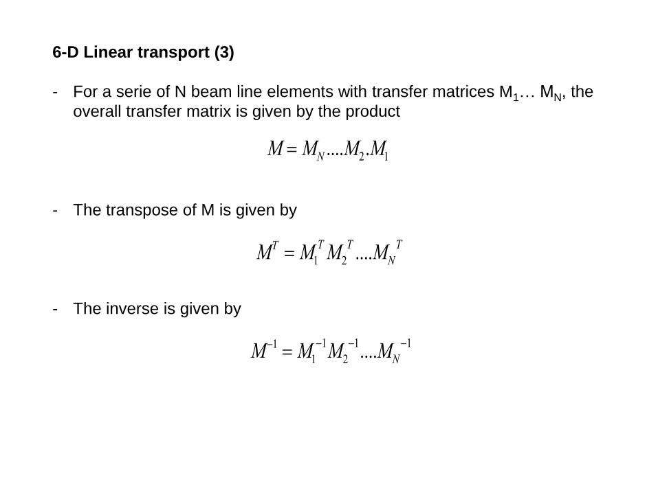
- For a serie of N beam line elements with transfer matrices M1… MN, the
overall transfer matrix is given by the product
- The transpose of M is given by
- The inverse is given by
M MN ....M2.M1
MT M1
TM2
T....MN
T
M1 M1
1M2
1....MN
1

6-D transport matrix for SCL elements
- Elements that will be introduced
- Drift, Quadrupole, Solenoid, RF cavity
- Longitudinal phase space notations and relations
c
zt
b If z>0 the particle is in front
thus earlier in time and t<0
b
bb
360ctcz
,, tz Distance, time and phase of a particle
with respect to reference particle
KE
KE
p
p ,,
b
b Fractional difference of momentum,
velocity and kinetic energy of a particle
with respect to reference particle

6-D transport matrix for SCL elements – drift
- Transverse motion seen before. Let’s look at longitudinal motion
- To cross a drift of length L, the reference particle needs
- Another particle with different energy will be early (t<0) or late (t>0)
- And writing for z and p/p leads to
- Thus, for a drift of length L
100000
/10000
001000
00100
000010
00001
2gL
L
L
M
c
Lt
b
b
b
bb
b
c
L
c
Lt
2
p
pLz
2g
10
/1
10
1
2gLM
LMM
zz
yyxx

p
pLz
2g
Homework 3-2
- Show that in a drift of length L the position and p/p are related by

6-D transport matrix for SCL elements – drift illustration (excel spreadsheet)
Beam M= Xi Xf
Mu 938.2723 MeV/c2 x 1.00 1.00 0 0 0 0 x 0 0 mm 1.00 0.00 -1.00 0.00 1.00
A 1 x' 0.00 1.00 0 0 0 0 x' 0 0 mrad 0.00 1.00 0.00 -1.00 0.00
Q 1 y 0 0 1.00 1.00 0 0 y 0 0 mm 1.00 0.00 -1.00 0.00 1.00
beta 0.428 y' 0 0 0.00 1.00 0 0 y' 0 0 mm 0.00 1.00 0.00 -1.00 0.00
gamma 1.107 z 0 0 0 0 1.00 0.82 z 0 0 mm 1.00 0.00 -1.00 0.00 1.00
pc 444.583 MeV/u dp/p 0 0 0 0 0.00 1.00 dp/p 0 0 mrad 0.00 1.00 0.00 -1.00 0.00
E 1038.272 MeV/u
KE 100.000 MeV/u
pc tot 444.6 MeV
Etot 1038.3 MeV
KE tot 100.0 MeV
Brho 1.483 Tm
Element
Length 1.000 m
-3.00
-2.00
-1.00
0.00
1.00
2.00
3.00
-3.00 -2.00 -1.00 0.00 1.00 2.00 3.00
xx'
-3.00
-2.00
-1.00
0.00
1.00
2.00
3.00
-3.00 -2.00 -1.00 0.00 1.00 2.00 3.00
yy'
-3.00
-2.00
-1.00
0.00
1.00
2.00
3.00
-3.00 -2.00 -1.00 0.00 1.00 2.00 3.00
zz'
100000
/10000
001000
00100
000010
00001
2gL
L
L
M

6-D transport matrix for SCL elements – quadrupole (1)
- A magnetic quadrupole of radial aperture a has hyberbolic pole shapes such that
- Motion for x
GxB
GyB
aBG
y
x
poletip
/ˆ
0
cGxm
qx
cGxq
BvBvEqF yzzyxx
b
b
x
y
z
Example of a horizontally
focusing and vertically
defocusing quadrupole for
a positive electric charge

6-D transport matrix for SCL elements – quadrupole (2)
- Equation of motion in x
- Introduce derivative with respect to s
- Equation of motion of the form
- Similarly for y
0 cGxm
qx b
0''
01
''
01
''2
xB
Gx
GxcM
e
A
Qx
cGxM
e
A
Qcx
u
u
bg
bg
b
0'' Kxx
0'' Kyy
With B
GK

6-D transport matrix for SCL elements – quadrupole (3)
- Thus we conclude that for a quadrupole of length L
- No force acting in z direction so a quadrupole of length L acts as a drift and
- If one switch the polarity of the B field one gets a focusing effect in y and a
defocusing effect in x
- A quadrupole is always focusing in one transverse direction and defocusing
in the other direction
10
/1 2gLM zz
LKLKK
LKK
LKM xx
cossin
sin1
cos
LKLKK
LKK
LKM yy
coshsinh
sinh1
cosh
focusing
defocusing

6-D transport matrix for SCL elements – quad illustration (excel spreadshit)
Beam M= Xi Xf
Mu 938.2723 MeV/c2 x 0.87 0.24 0 0 0 0 x 0 0 mm 1 0 -1 0 1
A 1 x' -1.04 0.87 0 0 0 0 x' 0 0 mrad 0 1 0 -1 0
Q 1 y 0 0 1.14 0.26 0 0 y 0 0 mm 1 0 -1 0 1
beta 0.145 y' 0 0 1.14 1.14 0 0 y' 0 0 mm 0 1 0 -1 0
gamma 1.011 z 0 0 0 0 1.00 0.24 z 0 0 mm 1 0 -1 0 1
pc 137.352 MeV/u dp/p 0 0 0 0 0.00 1.00 dp/p 0 0 mrad 0 1 0 -1 0
E 948.272 MeV/u
KE 10.000 MeV/u
pc tot 137.4 MeV
Etot 948.3 MeV
KE tot 10.0 MeV
Brho 0.458 Tm
Element
Length 0.250 m
G 2.00 T/m
K 4.37 m-2
sqrt(K) 2.09 m-1
sqrt(K)L 0.52 rad
-3
-2
-1
0
1
2
3
-3 -2 -1 0 1 2 3
xx'
-3
-2
-1
0
1
2
3
-3 -2 -1 0 1 2 3
yy'
-3
-2
-1
0
1
2
3
-3 -2 -1 0 1 2 3
zz'
LKLKK
LKK
LKM xx
cossin
sin1
cos
LKLKK
LKK
LKM yy
coshsinh
sinh1
cosh
10
/1 2gLM zzB
GK

6-D transport matrix for SCL elements – solenoid (1)
- Solenoid can be used to focus the beam. We’ll see that solenoids couple the
x and y direction.
- Let’s consider a solenoid of length L with N turns and current I. The magnetic
fields are given by
enclosedIldB 0.
z
Bz
r
zr
r
2
z
B2
rdzB
0dzBr2rB
0sd.B
zr 'B2
rB
-B’z
IL
NBz 0

z
zrz
B2
qrp
dz
dB
2
qr
dz
dp
dz
dB
2
rqv
dt
dz
dz
dpBqv
dt
dp
Bvqdt
pd
yp2
qB
p
p'x
y2
qBsinB
2
qrsinpp
z
z
z
x
zzx
B2
B
p2
qBˆk z
z
z
xk'y
yk'x
100
0100
010
0001
k
kM entry
100
0100
010
0001
k
kM exit
6-D transport matrix for SCL elements – solenoid (2)
- As an approximation one can look at the solenoid as a three-piece process
- Entry region, body region, and exit region
- In entry and exit regions one has to look into the action of the radial field
- In the body region one has to look at the action of the longitudinal
magnetic field
x
y
z
qBz>0
x
y
z
qBz<0
Fringe field of the solenoid imparts angular momentum to the beam

6-D transport matrix for SCL elements – solenoid (3)
- In the body of the solenoid, the magnetic field is constant and along the z-
axis. The motion is circular in the x-y plane
- Over the length L of the solenoid, the total rotation angle is
- Angle transformation
- Position transformation
kLB
LB
p
qLB
v
L
m
qBt z
z
z
z
zcross 2
cossin
sincos
iif
iif
yxy
yxx
Lx
v
v
v
v
v
v
Ly
v
v
v
v
v
v
iz
z
xx
iz
z
yy
ii
ii
1sin
1cos
cos1sin
sin1
1cos1
sinsin1coscos
coscos
Ly
Lxxx
Lx
Lyxx
xx
xx
xxx
iiif
iiif
if
if
if
using
v
xv
yv
y
x
2/

6-D transport matrix for SCL elements – solenoid (4)
- Similarly for y
- Thus the angle and position transformations yield for the body transfer matrix
- With and k same sign as qBz
sincos1
sin1
1cos1
sinsin1cossin
sinsin
Ly
Lxyy
Ly
Lxyy
yy
yy
yyy
iiif
iiif
if
if
if
cos0sin0
sin1cos10
sin0cos0
cos10sin1
LL
LL
M body
kL2
kLkLk
kL
k
kL
kLkLk
kL
k
kL
M body
2cos02sin02
2sin1
2
2cos10
2sin02cos02
2cos10
2
2sin1
giving

6-D transport matrix for SCL elements – solenoid (5)
- The total transfer matrix for a solenoid of field strength B and length L is given
by the product of the entry, body and exit matrices
- using short-hand notations c=coskL and s=sinkL
- The determinant of 2x2 diagonal blocks Mxx and Myy are not equal to 1
- The xx’ and yy’ emittances are not preserved
- The Mxy and Myx matrices are non-null indicating coupling between the
transverse dimensions through a solenoid
entrybodyexit MMMM ..
100000
/10000
00
00//
00
00//
2
22
22
22
22
gL
ckscscks
kscckssc
sckscksc
kssckscc
M
B
Bk
2

6-D transport matrix for SCL elements – solenoid (6)
- One can rewrite the solenoid matrix as a product of two matrices. A global
focusing matrix in both xx’ and yy’ plans and a rotation matrix
- Thus, a solenoid is equivalent to a focusing in both transverse dimensions
and a rotation of the xy space of angle kL
focusing. MMM rotationsolenoid
kLkL
kLkL
kLkL
kLkL
M rotation
cos0sin0
0cos0sin
sin0cos0
0sin0cos
kLkLk
kkLkL
kLkLk
kkLkL
M
cossin00
/sincos00
00cossin
00/sincos
focusing

6-D transport matrix for SCL elements – solenoid illustration (excel spreadsheet)
Beam M= Xi Xf
Mu 938.2723 MeV/c2 x 0.47 0.15 0.50 0.16 0.00 0.00 x 0 0 mm 1 0 -1 0 1
A 1 x' -1.63 0.47 -1.75 0.50 0.00 0.00 x' 0 0 mrad 0 1 0 -1 0
Q 1 y -0.50 0.16 0.47 0.15 0.00 0.00 y 0 0 mm 1 0 -1 0 1
beta 0.145 y' 1.75 -0.50 -1.63 0.47 0.00 0.00 y' 0 0 mm 0 1 0 -1 0
gamma 1.011 z 0.00 0.00 0.00 0.00 1.00 0.24 z 0 0 mm 1 0 -1 0 1
pc 137.352 MeV/u dp/p 0.00 0.00 0.00 0.00 0.00 1.00 dp/p 0 0 mrad 0 1 0 -1 0
E 948.272 MeV/u
KE 10.000 MeV/u
pc tot 137.4 MeV
Etot 948.3 MeV
KE tot 10.0 MeV
Brho 0.458 Tm
Element
Length 0.250 m
B 3.00 T
k 3.27 m-1
kL 0.82 rad
cosKL 0.68
sinKL 0.73
-3
-2
-1
0
1
2
3
-3 -2 -1 0 1 2 3
xx'
-3
-2
-1
0
1
2
3
-3 -2 -1 0 1 2 3
yy'
-3
-2
-1
0
1
2
3
-3 -2 -1 0 1 2 3
zz'
100000
/10000
00
00//
00
00//
2
22
22
22
22
gL
ckscscks
kscckssc
sckscksc
kssckscc
Msolenoid
B
Bk
2
focusing. MMM rotationsolenoid
kLkL
kLkL
kLkL
kLkL
M rotation
cos0sin0
0cos0sin
sin0cos0
0sin0cos
kLkLk
kkLkL
kLkLk
kkLkL
M
cossin00
/sincos00
00cossin
00/sincos
focusing

Comparison of quadrupole and solenoid focusing
- The focusing terms (M21) for quadrupole and solenoids are as follow
- Assuming the focusing is not too strong one has approximately
kLkM
LKKM
sin
sin
21
21
Quadrupole
Solenoid
BBk
BGK
2/
/
with
4
2
21
21
L
B
BM
a
L
B
BM
Quadrupole
Solenoid
Beam Brho 5 Tm
Quad Length 0.5 m
rad apert 10 cm
B pole tip 0.5 T
Sol Length 0.5 m
B 7 T
M21 quad -0.479 m
M21 sol -0.240 m
f quad 2.086 m
f sol 4.166 m
- Thus, solenoids are typically better
suited for lower rigidity beams or require
strong magnetic fields.

6-D transport matrix for SCL elements – RF gap (1)
- For ion linacs, the beam must be injected off-crest with a negative average phase
such that a restoring force keep the beam bunched
- Late particles see a higher accelerating field, early particle a weaker accelerating
field.
- On-axis field is of the form
is the phase of the field when the particle arrives at cell center (z=t=0)
- When =0 (t=0), the field is maximum
is called average or synchronous phase in the cell
- Examples:
=-30 degrees means particle arrives at center 30 degrees before the peak.
=+30 degrees means particle arrives at center 30 degrees after the peak.
)cos(, tzEtzE zz

6-D transport matrix for SCL elements – RF gap (2)
- We consider the EM fields in cylindrically symmetric structure near the beam
axis and follow the development from T. Wangler. The longitudinal electric
field is in good approximation independent of the radial position
- The transverse fields are linearly dependent on the radial position and can be
expressed with respect to the derivatives of the longitudinal accelerating field
- The change in transverse momentum is given by integration of the transverse
fields across the length L of the accelerating gap
rt
E
cB z
22
1
rz
EE z
r
2
1
szz tzEtzrE cos)(,,
2/
2/
2/
2/
2
L
L
zz
L
Lrr
c
dz
t
E
cz
Er
q
c
dzcEqp
b
b
bb

6-D transport matrix for SCL elements – RF gap (3)
- One then substitute the partial derivative with respect to the longitudinal
position with the total derivative using
- To get
- Assuming the longitudinal electric field vanishes at both extremities of the RF
gap, only the second term subsists
- Assuming the field distribution is symmetric and writing kz instead of t gives
t
E
cz
E
dz
dE zzz
b
1
2/
2/2
L
L
zzr
c
dz
t
E
cz
Er
qp
b
b
2/
2/
1
2
L
L
zzr dz
t
E
ccdz
dE
c
qrp
b
bb
dztzEc
qrp
L
Lszr
2/
2/222sin
2
bg
2/
2/222cossin
2
L
Lzsr kzdzzE
c
qrp
bg

6-D transport matrix for SCL elements – RF gap (4)
- The last term is the E0TL and using instead of gives
- One can separate in x and y components and since transfer matrices are
calculated in the x’ and y’ coordinates rather than momentum, it is convenient
to use
- And conclude
rc
TLEqp s
rgb
22
0 sin
cAm
px
u
x 'bg
cAm
py
u
y 'bg
xcm
TLE
A
Qx s
u
gb
bg sin'
2
0
22
ycm
TLE
A
Qy s
u
gb
bg sin'
2
0
22

6-D transport matrix for SCL elements – RF gap (5)
- In the longitudinal direction one has for the reference particle
- Where s is the phase in the middle of the gap for the reference particle
- The change of momentum for another particle is
- Looking at the variation in momentum difference caused by the RF gap
s
L
Ls
L
Ls
L
Lzrefz
c
TLqE
dzkzzEc
q
dztzEc
q
c
dzEqp
b
b
b
b
cos
cos)(cos
cos)(
0
2/
2/
2/
2/
2/
2/,
b
szc
TLqEp cos0
where evaluated at the center of the gap
ssrefzzc
TLqEppp
b coscos0
,

6-D transport matrix for SCL elements – RF gap (6)
- For small
- And since one gets
- As for transverse dimension one has and thus
zcb
sc
TLqEp
b sin0
zc
TLEqp s
22
0 sin
b
cAm
p
p
p
u
bg
zcm
TLE
A
Q
p
ps
u
b
bg sin
22
0
2

6-D transport matrix for SCL elements – RF gap (7)
- The change in normalized momentum components caused by the RF gap are
- Since the usual coordinate system use x’, y’ and dp/p one has first to
transform to normalized momentum, apply the equations above and the
change in beam energy, and then transform back into the x’, y’ and p/p
coordinates.
- The total transfer matrix for a RF gap is then
zkp
p
yky
xkx
22
'
'
g
bg
bg
bg
s
ucm
TLE
A
Qk
gb
sinˆ
2
0
22with
if
yyxx kM
bgbg 0
01
1
01
/10
01,
if
zz kM
bggbg 0
01
12
01
/10
012
fif
zz
fif
yyxx
kM
kM
bgbgbgg
bgbgbg
//2
01
//
01
2
,

6-D transport matrix for SCL elements – RF gap (8)
- The momentum kicks from the RF gap are
- To accelerate and focus the beam longitudinally
is chosen between -90 and 0 degrees
- k>0 and there is a restoring force in the longitudinal dimension
- the rf gap produces a defocusing force in the transverse dimensions
- The stronger the longitudinal focusing, the stronger the transverse
defocusing
- As the beam energy increases both focusing and defocusing effects
decrease
kzp
p
kyy
kxx
22
'
'
g
bg
bg
bg
s
ucm
TLE
A
Qk
gb
sinˆ
2
0
22with

6-D transport matrix for SCL elements – rf gap (excel spreadsheet)
Beam initial Beam final M= Xi Xf
Mu 938.2723 MeV/c2 Mu 938.2723 MeV/c2 x 1.000 0.000 0 0 0 0 x 0 0 mm 1 0 -1 0 1
A 1 A 1 x' 0.101 0.984 0 0 0 0 x' 0 0 mrad 0 1 0 -1 0
Q 1 Q 1 y 0 0 1.000 0.000 0 0 y 0 0 mm 1 0 -1 0 1
beta 0.550 beta 0.556 y' 0 0 0.101 0.984 0 0 y' 0 0 mm 0 1 0 -1 0
gamma 1.197 gamma 1.203 z 0 0 0 0 1.000 0.000 z 0 0 mm 1 0 -1 0 1
pc 617.564 MeV/u pc 627.745 MeV/u dp/p 0 0 0 0 -0.289 0.984 dp/p 0 0 mrad 0 1 0 -1 0
E 1123.272 MeV/u E 1128.901 MeV/u
KE 185.000 MeV/u KE 190.629 MeV/u
pc tot 617.6 MeV pc tot 627.7 MeV
Etot 1123.3 MeV Etot 1128.9 MeV
KE tot 185.0 MeV KE tot 190.6 MeV
Brho 2.060 Tm Brho 2.094 Tm
Element
f 805.000 MHz
E0 10.000 MV/m
T 0.650
L 1.000 m
phi -30.00 deg
E0TL 6.50 MV
lambda 0.37 m
k 0.07 m-1
dKE gap 5.63 MeV/u
bg ini 0.66
bg fin 0.67
bet lamb 0.20 m
z=1mm 1.76 rf deg
bgi/bgf 0.98
-3
-2
-1
0
1
2
3
-3 -2 -1 0 1 2 3
xx'
-3
-2
-1
0
1
2
3
-3 -2 -1 0 1 2 3
yy'
-3
-2
-1
0
1
2
3
-3 -2 -1 0 1 2 3
zz'
fif
zz
fif
yyxx
kM
kM
bgbgbgg
bgbgbg
//2
01
//
01
2
,
s
ucm
TLE
A
Qk
gb
sinˆ
2
0
22

6-D transport matrix for SCL elements – rf cell (excel spreadsheett)
Beam initial Beam final M= Xi Xf
Mu 938.2723 MeV/c2 Mu 938.2723 MeV/c2 x 1.05 1.02 0 0 0 0 x 0 0 mm 1 0 -1 0 1
A 1 A 1 x' 0.10 1.03 0 0 0 0 x' 0 0 mrad 0 1 0 -1 0
Q 1 Q 1 y 0 0 1.05 1.02 0 0 y 0 0 mm 1 0 -1 0 1
beta 0.550 beta 0.556 y' 0 0 0.10 1.03 0 0 y' 0 0 mm 0 1 0 -1 0
gamma 1.197 gamma 1.203 z 0 0 0 0 0.90 0.66 z 0 0 mm 1 0 -1 0 1
pc 617.564 MeV/u pc 627.745 MeV/u dp/p 0 0 0 0 -0.29 0.88 dp/p 0 0 mrad 0 1 0 -1 0
E 1123.272 MeV/u E 1128.901 MeV/u
KE 185.000 MeV/u KE 190.629 MeV/u
pc tot 617.6 MeV pc tot 627.7 MeV
Etot 1123.3 MeV Etot 1128.9 MeV
KE tot 185.0 MeV KE tot 190.6 MeV
Brho 2.060 Tm Brho 2.094 Tm
Element
f 805.000 MHz
E0 10.000 MV/m
T 0.650
L 1.000 m
phi -30.00 deg
E0TL 6.50 MV
lambda 0.37 m
k 0.07 m-1
dKE gap 5.63 MeV/u
bg ini 0.66
bg fin 0.67
bet lamb 0.20 m
z=1mm 1.76 rf deg
bgi/bgf 0.98
Mgap21 0.10 m-1
Mgap22 0.98
Mgap65 -0.29 m-1
Mgap66 0.98
-3
-2
-1
0
1
2
3
-3 -2 -1 0 1 2 3
xx'
-3
-2
-1
0
1
2
3
-3 -2 -1 0 1 2 3
yy'
-3
-2
-1
0
1
2
3
-3 -2 -1 0 1 2 3
zz'

2/
2/
0 )(1
2
L
L
gz EdzzEL
E
zkzb
Eg
z -L/2 L/2 0
Transit time factor – flat field distribution over the gap
- Let’s assume the field is constant across the gap
g
g
g
g
ETLEETET
b
bb
00
22
2/
2/sin
kL
kLT
22
2/
2/
2/
2/0
2/
2/
2/
2/0
0cos1
sin)(1
2/
2/sinsin1cos)(
1
SCT
k
kz
LdzkzzE
LES
kL
kL
k
kz
LdzkzzE
LEC
L
L
L
L
z
L
L
L
L
z
gEE 0
b
LkL g
g
2

kL
E
k
zk
L
Edzzk
LdzzE
LE
zkz
g
L
L
ggL
L
L
L
gz
2sincos
1)(
1
2
2/
2/
2/
2/
2/
2/
0
b
Transit time factor – sinusoidal field distribution over the gap
- Let’s assume the field is constant across the gap
0.0
0.1
0.2
0.3
0.4
0.5
0.6
0.7
0.8
0.9
1.0
0.0 0.2 0.4 0.6 0.8 1.0
Ez
z
sinus
Eg
-L/2 L/2 0
22
2/
2/0
2/
2/0
2/
2/0
2/
2/0
sincos1
sin)(1
coscos1
cos)(1
SCT
dzkzzkELE
dzkzzELE
S
dzkzzkELE
dzkzzELE
C
L
L
gg
L
L
z
L
L
gg
L
L
z
gEE
20
2222
2 )cos(12
2 Lk
kLT
g
g
g
g
ETLEETET42
14/ 00
b
bb
gbb
b
LkL g
g
2

Transit time factor – illustration
- Single gap with flat field and sinusoidal field
bgap=0.9
- At b=bg=0.9 T=2/ for flat field and /4 for sine field
- At b= bg/2, bg/4, bg/6 etc… T=0 for flat field
- At b= bg/3, bg/5, bg/7 etc… T=0 for sine field
2/
2/sin
kL
kLT flat
2222
2
sin
)cos(12
2 Lk
kLT

Field in elliptical cavities (inner cells) are sine-like
- Electric field on-axis for b0.61 at 805MHz cell from superfish
- Simple sinusoidal field also plotted for comparison
- Transit time factors calculated by superfish and from analytical formula for
sine field are close
- Sinusoidal field distribution is a reasonable approximation for accelerating
gaps in elliptical cavities

Homework 3-3
- Assume a 1 GHz single-cell rf cavity of 10 cm cell length with a sinusoidal
field on axis. What is the minimum E0 so that a 200 MeV proton beam could
experience the same transverse focusing as in a quadrupole of 10 cm length
and 1 T/m gradient?
- For this beam, what would the magnetic field in a 10cm long solenoid need to
be to also provide similar focusing?

2-D beam matrix (1)
- We assume the beam particles are all included in a 2D ellipses - The general equation of a centered ellipse can be written as
- where the coefficients are satisfying
- In matrix form, the ellipse equation is
- with
bg 22 xxx2x
bg 2 1
UT2D1U 1
2D1
1
2D
g
b
and
2D 2Db
g

2-D beam matrix (2) – graphical representation
- Beam emittance relates to the area of the ellipse A=
- Beam emittance is the square-root of the determinant of the beam matrix
,b, g relates to the shape of the ellipse
b relates to beam size in x
g relates to beam size in x’
relates to tilt angle of ellipse xx’
- only 2 independent parameters
g
b
2
max
2
max
'x
x
12 bg
bg 22 xxx2x
2D 2Db
g
g
g
sin'
sincosx
][0,2for contour ellipse
x
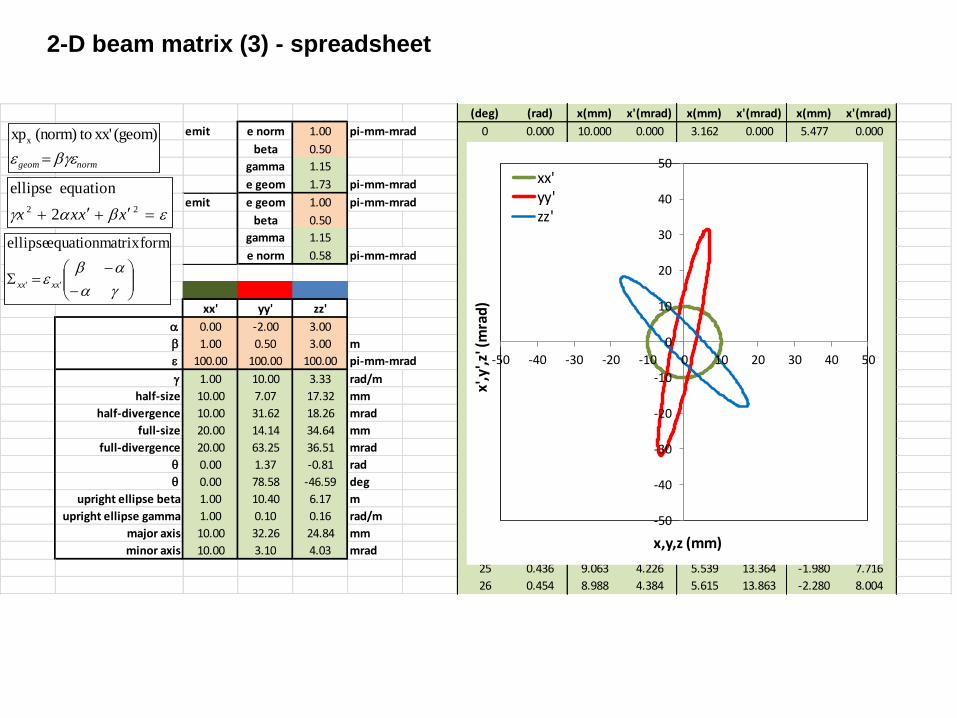
2-D beam matrix (3) - spreadsheet
(deg) (rad) x(mm) x'(mrad) x(mm) x'(mrad) x(mm) x'(mrad)
emit e norm 1.00 pi-mm-mrad 0 0.000 10.000 0.000 3.162 0.000 5.477 0.000
beta 0.50 1 0.017 9.998 0.175 3.272 0.552 5.190 0.319
gamma 1.15 2 0.035 9.994 0.349 3.381 1.104 4.900 0.637
e geom 1.73 pi-mm-mrad 3 0.052 9.986 0.523 3.489 1.655 4.610 0.956
emit e geom 1.00 pi-mm-mrad 4 0.070 9.976 0.698 3.596 2.206 4.318 1.274
beta 0.50 5 0.087 9.962 0.872 3.701 2.756 4.024 1.591
gamma 1.15 6 0.105 9.945 1.045 3.806 3.305 3.730 1.908
e norm 0.58 pi-mm-mrad 7 0.122 9.925 1.219 3.909 3.854 3.434 2.225
8 0.140 9.903 1.392 4.012 4.401 3.137 2.541
9 0.157 9.877 1.564 4.113 4.947 2.839 2.856
xx' yy' zz' 10 0.175 9.848 1.736 4.212 5.491 2.541 3.170
0.00 -2.00 3.00 11 0.192 9.816 1.908 4.311 6.034 2.241 3.484
b 1.00 0.50 3.00 m 12 0.209 9.781 2.079 4.408 6.575 1.941 3.796
100.00 100.00 100.00 pi-mm-mrad 13 0.227 9.744 2.250 4.504 7.114 1.641 4.107
g 1.00 10.00 3.33 rad/m 14 0.244 9.703 2.419 4.598 7.650 1.339 4.417
half-size 10.00 7.07 17.32 mm 15 0.262 9.659 2.588 4.691 8.185 1.038 4.725
half-divergence 10.00 31.62 18.26 mrad 16 0.279 9.613 2.756 4.783 8.716 0.736 5.032
full-size 20.00 14.14 34.64 mm 17 0.297 9.563 2.924 4.873 9.246 0.434 5.338
full-divergence 20.00 63.25 36.51 mrad 18 0.314 9.511 3.090 4.962 9.772 0.131 5.642
0.00 1.37 -0.81 rad 19 0.332 9.455 3.256 5.049 10.295 -0.171 5.944
0.00 78.58 -46.59 deg 20 0.349 9.397 3.420 5.135 10.816 -0.473 6.244
upright ellipse beta 1.00 10.40 6.17 m 21 0.367 9.336 3.584 5.219 11.333 -0.775 6.543
upright ellipse gamma 1.00 0.10 0.16 rad/m 22 0.384 9.272 3.746 5.301 11.846 -1.077 6.839
major axis 10.00 32.26 24.84 mm 23 0.401 9.205 3.907 5.382 12.356 -1.379 7.134
minor axis 10.00 3.10 4.03 mrad 24 0.419 9.135 4.067 5.461 12.862 -1.680 7.426
25 0.436 9.063 4.226 5.539 13.364 -1.980 7.716
26 0.454 8.988 4.384 5.615 13.863 -2.280 8.004
-50
-40
-30
-20
-10
0
10
20
30
40
50
-50 -40 -30 -20 -10 0 10 20 30 40 50
x',y
',z' (
mra
d)
x,y,z (mm)
xx'yy'zz'bg 22 2
equation ellipse
xxxx
normgeom bg
(geom) xx' to(norm) xpx
g
b ''
formmatrix equation ellipse
xxxx

6-D beam matrix (1)
- For 6-D linear transport system, it is convenient to represent the beam as a 6-D hyperellipsoid.
- The matrix represents the hyperellipsoid coefficients
- 6 diagonal elements are the beam square sizes in each dimension - 30 off-diagonal elements represent the tilt of the ellipsoid in each plane - Determinant of the 3 diagonal 2x2 sub-blocks are related to 2-D emittances in
the xx’, yy’ and zz’ planes
- Upright in 6-D means all off-axis terms are zeros (ellipses are all upright in
the 2-D projections)
- 6-D volume is proportional to the sqrt of determinant of the 6-D beam matrix
UT 1U 1
xx xy xz
yx yy yz
zx zy zz
view of a 3D ellipsoid

6-D beam matrix (2)
- If there is no correlation between xx’, yy’ and zz’ phase spaces
- Property of a block diagonal matrix A
- For a block diagonal beam matrix, 6-D beam volume is proportional to the
product of 2-D xx’, yy’, and zz’ emittances
zz
yy
xx
00
00
00
k
2
1
A00
0A0
00A
A
k21 AdetAdetAdetAdet
zyxDV
6
3
6

6-D beam matrix transport
- Considering the linear transformation of the phase space coordinates introduced earlier
- gives - from the hyperellipsoid equation
- The hyperellipsoid matrix transforms as
- If M is symplectic (determinant=1), the 6-D volume phase space is a constant during transport
U1 MU0
U0
T0
1U0 1
U1TMT
1
01M 1U1 1
U1TM0M
T 1
U1 1
U0 M1U1 and U0T
U1TM1
T
U1TMT
1
1 M0MT

Beam matrix transport - spreadsheet
INPUT xx' yy' zz' OUTPUT xx' yy' zz'
-2.00 0.00 0.00 0.53 0.00 0.00
b 2.82 2.82 1.98 m b 16.28 2.82 1.98 m
100.00 100.00 100.00 pi-mm-mrad S0 M S1 100.00 100.00 100.00 pi-mm-mrad
g 1.77 0.35 0.51 rad/m Sxx 282.0 200.0 0.294453 2.69 1627.8 -52.9 Sxx g 0.08 0.36 0.51 rad/m
half-size 16.79 16.79 14.07 mm 200.0 177.3 -0.3391 0.29 -52.9 7.9 half-size 40.35 16.78 14.06 mm
half-divergence 13.32 5.95 7.11 mrad Syy 282.0 0.0 0.29 2.69 281.7 0.0 Syy half-divergence 2.80 5.96 7.11 mrad
full-size 33.59 33.59 28.14 mm 0.0 35.5 -0.34 0.29 0.0 35.5 full-size 80.69 33.57 28.12 mm
full-divergence 26.63 11.91 14.21 mrad Szz 198.0 0.0 -0.31 1.88 197.8 0.0 Szz full-divergence 5.61 11.92 14.22 mrad
0.66 0.00 0.00 rad 0.0 50.5 -0.48 -0.31 0.0 50.6 -0.03 0.00 0.00 rad
37.67 0.00 0.00 deg -1.87 -0.01 0.02 deg
upright ellipse beta 4.36 2.82 1.98 m upright ellipse beta 16.29 2.82 1.98 m
upright ellipse gamma 0.23 0.35 0.51 rad/m upright ellipse gamma 0.06 0.36 0.51 rad/m
major axis 20.89 16.79 14.07 mm major axis 40.37 16.78 14.06 mm
minor axis 4.79 5.95 7.11 mrad minor axis 2.48 5.96 7.11 mrad
-50
-40
-30
-20
-10
0
10
20
30
40
50
-50 -40 -30 -20 -10 0 10 20 30 40 50
x',y
',z' (
mra
d)
x,y,z (mm)
xx'
yy'
zz'
-50
-40
-30
-20
-10
0
10
20
30
40
50
-50 -40 -30 -20 -10 0 10 20 30 40 50
x',y
',z' (
mra
d)
x,y,z (mm)
xx'
yy'
zz'

Trace 3D
- Trace-3D is a beam dynamics program that calculates the envelopes of a bunched beam through a trasnport system
- The beam is represented as a hyperellipsoid in 6-D phase space and the transport is done through 6x6 matrices for various elements used in particle accelerators
- Example

Homework 3-4
- Assume a 700 MHz 5 cell rf cavity of 0.56 geometrical beta cell length with a
pure sinusoidal field on axis and E0=10 MV/m.
- What is the final energy for a 300 MeV proton beam passing through that
cavity tuned for -30 deg phase?
- Using Trace3D. What are the final beam twiss parameters (transverse and
longitudinal) for that beam if the twiss parameters at the entrance are x=1
bx=1m , y=1 by=1m, z=0 bz=1m? In the case where the five cells are
treated as 5 consecutive rf gaps or if all the rf-kicks are applied in a single
equivalent rf gap?

Trace 3D – template inpout file
- 20 elements put in (all drifts of 0m length)

Trace 3D – template inpout file
- Quadrupole of G=20 T/m gradient and 150 mm length

Trace 3D – template inpout file
- Solenoid with B=6 T (60,000 G) field and 500 mm length

Trace 3D – rf example
- Single rf gap with E0TL=10 MV/m and -45 deg phase and 50cm drifts on each side


![Behavioral Core Protocols and Training Balance Beam · 2016-08-11 · Behavioral Core Protocols and Training Balance Beam Basics The balance beam is a test of motor coordination [1-4].](https://static.fdocuments.in/doc/165x107/5f0eeed37e708231d441a731/behavioral-core-protocols-and-training-balance-2016-08-11-behavioral-core-protocols.jpg)