SidePlate Modeling Basics · SidePlate Modeling Basics ... RAM Frame – Assign – Beams – Frame...
23
For more information: Toll Free 800.475.2077 Tel 949.238.8900 www.sideplate.com Page 1 of 23 SidePlate Modeling Basics 09/29/2017 in RAM Structural System
Transcript of SidePlate Modeling Basics · SidePlate Modeling Basics ... RAM Frame – Assign – Beams – Frame...

For more information: Toll Free 800.475.2077 Tel 949.238.8900 www.sideplate.com
Page 1 of 23
SidePlate Modeling Basics
09/29/2017
in RAM Structural System

For more information: Toll Free 800.475.2077 Tel 949.238.8900 www.sideplate.com
Page 2 of 23
How to Model SidePlate Moment Connections in RAM
1. Identify your lateral frame members in RAM Modeler, and Validate your model. Page 4-12.
2. RAM Frame – Assign – Beams – Frame Beam Connection Type: assign SidePlate to
Both Ends, Left End, or Right End of SidePlate MF beams appropriately.
Once the beam ends have been assigned, RAM Frame will display a red rectangle symbolizing a
SidePlate moment connection.
NOTE: if you pin a member to test its usefulness in your system, or to perform a rho check, but don’t remove
the SidePlate connections, it will remain partially fixed.

For more information: Toll Free 800.475.2077 Tel 949.238.8900 www.sideplate.com
Page 3 of 23
3. RAM Frame – Criteria – General: Rigid End Zones can remain at Ignore Effects. For SidePlate,
it does not matter what is checked here, as the SidePlate Feature will implement 100% rigid (or
0% Reduction) panel zone, as proven by testing.
4. RAM Frame – Criteria – SidePlate: assign the correct SidePlate stiffness to the joints. R=8 for
High Seismic connections (SMF, IMF or OMF applications), and R=3 for Low Seismic (R=3
Bolted applications).
5. RAM FRAME – Drift Control Points – View Results : See 30% reduction in
drifts due to the SidePlate stiffness for R=8 SMF Bolted or Welded.
6. Choose reduced beam and column sizes, optimized for SidePlate. For typical projects, choose a
beam and column sizes that are 20% to 30% lighter than a conventional design, and start there.
In really high seismic, choose beams that are 40% to 50% lighter.
7. GEOMETRIC COMPATIBILITY (RAM 15.04 is programed to give you a warning if bbf + 1.5” < bcf,
however this will be updated to the Bolted Geometric Compatibility limit below)
• BOLTED GEOMETRIC COMPATIBILITY: bbf + 1” ≤ bcf
• WELDED GEOMETRIC COMPATIBILITY: bbf + 1.1*tbf + 1/2” ≤ bcf
NOTE: R=8 is the RAM default. If you are using an SMF, IMF or OMF connection (Field Bolted or Field
Welded), you should use the High Seismic (r=8) stiffness for Both Seismic and Wind loading.
NOTE: For R=3 Bolted (low seismic), the drift reductions could be between 15%-20%
NOTE: For more background information regarding SidePlate and Geometric Compatibility, refer to our
Engineering Design Guidelines document.

For more information: Toll Free 800.475.2077 Tel 949.238.8900 www.sideplate.com
Page 4 of 23
Model Validation Tips for RAM (General for any Moment Frame Systems)
1. Under RAM Manager - Criteria – Self-Weight: check that you are self-calculating Beams,
Columns, Walls, and Slabs/Decks as you have intended.
2. RAM Modeler – Integrity – Data Check – Integrated: confirm there are no identified
modeling errors or warnings.
3. RAM Modeler – Layout – Loads Surface Loads AND Line Loads : check that
Superimposed Loads and Line Loads have the correct Mass DL identified, and have been
applied to every floor, as intended.
NOTE: Steel joists cannot be self-calculated and need to be added to the superimposed dead load and mass
NOTE: This simple step can save hours of headaches to identify modeling errors before they can cause invalid
results.
NOTE: partition loads are not included in the Mass, and need to be added, 10 psf Floor and 4 psf Roof, per
code, when appropriate

For more information: Toll Free 800.475.2077 Tel 949.238.8900 www.sideplate.com
Page 5 of 23
4. RAM Modeler – Layout – Slab – Deck Assign : check that deck properties and weights are
as intended and applied to each level, especially when slab/deck is self-calculated. If you are
using semi-rigid diaphragms, check that the Effec Thick, Poisson, and Elastic Mod are entered
correctly.

For more information: Toll Free 800.475.2077 Tel 949.238.8900 www.sideplate.com
Page 6 of 23
5. RAM Modeler – Options – Set Show Options : allows you to quickly scroll through the layout
levels to check that the correct loads or decks are applied.
6. RAM Modeler – Layout – Slab Slab Edge : confirm that your slab edge
is adequate to fit ½ your column depth or width plus SidePlate connection.
When information is not yet available for the exact slab edge, we recommend you use 12
inches. This will accommodate most SidePlate designs. SidePlate approximate minimum
slab edge can be calculated below (we recommend you consider adding up to a ½ inch of
tolerance to these minimum slab edge calculations):
• When column web is perpendicular to slab edge
� SidePlate® Field Bolted or Welded – ½* dc + tbf + ½”
If slab edge is critical, the column can be shifted inside the building, “off - grid”
• When column web is perpendicular to slab edge (Along Grid A in Fig 8)
� SidePlate® Field Bolted or Welded – ½* dc + bcf + ½”
• When column web is parallel to slab edge (Along Grid 1 in Fig 8)
� SidePlate® Field Bolted, Standard – ½* bcf + tbf + 4”
� SidePlate® SMF Field Bolted, Standard – ½* bcf + 1.25* tbf + 1/8” + 4”
� SidePlate® SMF Field Welded – ½* bcf + 2* tbf + ½”
NOTE: If slab edge is critical, we can use our narrow bolted configuration that moves the top set of angles from
the outside face of the side plates to the inside face of the side plates to eliminate the 4” (or replace it with 1 1/2”
for bolt nut).
For more information: Toll Free 800.475.2077 Tel 949.238.8900 www.sideplate.com
Page 7 of 23
8. RAM Modeler – Story…: check story heights and column splice locations are as intended.
9. Beam Design
10. Column Design
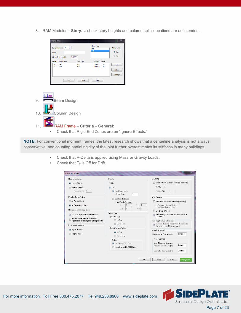
11. RAM Frame – Criteria – General:
• Check that Rigid End Zones are on “Ignore Effects.”
• Check that P-Delta is applied using Mass or Gravity Loads.
• Check that Tb is Off for Drift.
NOTE: For conventional moment frames, the latest research shows that a centerline analysis is not always
conservative, and counting partial rigidity of the joint further overestimates its stiffness in many buildings.

For more information: Toll Free 800.475.2077 Tel 949.238.8900 www.sideplate.com
Page 8 of 23
12. RAM Frame – Criteria – Diaphragm: check that intended diaphragms are Rigid or Semi-Rigid.
If you are using Pseudo-Flexible diaphragms verify the correct distribution of loads are
applied at Loads – Pseudo Flexible Diaphragm Properties: every frame must be manually
assigned the correct proportion of Wind, Seismic, Notional, and Dynamic loads, as applies.
Every frame must be carefully numbered at Assign – Frame Numbers.
NOTE: If you are using Semi-Rigid diaphragms, check that the Mesh Controls are not larger than your smallest
(lateral frame beam span)/4 to ensure accurate results. The current RAM default is 4 ft.
NOTE: When you add a frame member it is automatically assigned to 0, and must be re-numbered. Also,
Pseudo Flexible Diaphragms can cause short buildings to have inaccurate periods.

For more information: Toll Free 800.475.2077 Tel 949.238.8900 www.sideplate.com
Page 9 of 23
13. RAM Frame – Criteria – Ground Level: confirm that the lateral analysis is starting at the base, or
the correct level, when modeling a basement or steel grade beams.
14. RAM Frame – Loads – Exposure: confirm that the appropriate parapet(s) have been assigned.
15. RAM Frame – Loads – Diaphragm Masses: confirm that there are no masses in the list without
a number under “Diaph.#,” and if any are listed as “none,” determine the appropriate floor and
assign that diaphragm under “Combine To.”
NOTE: This is usually caused by flying beams or columns that are outside the modeled diaphragm. The same
can be repeated for gravity loads.

For more information: Toll Free 800.475.2077 Tel 949.238.8900 www.sideplate.com
Page 10 of 23
16. RAM Frame – Loads – Show Member Options: to
turn floors and gravity memebers off to see the frames better.
17. RAM Frame – Loads – Show Member Options : view Fixity – “All” and “Major Axis” in 3D
and by floor, to determine that all Moment Frame Beams and Columns have appropriate Fixity
applied.
18. RAM Frame – Reports –Takeoff, skip to bottom , TOTAL STRUCTURE FRAME TAKEOFF:
• Record the Total Floor Area, to be used to validate the building mass.
19. RAM Frame – Process – Analyze: run ALL load cases with Tb Off.
20. RAM Frame – Reports – Loads and Applied Forces:
• Verify that all the seismic and wind factors are inputted accurately.
• Record the Total Building Weight (kips) from the seismic load case. Calculate Total
Building Weight / Total Building Area (from Takeoff report) to get Average Mass. Verify
that the average mass is reasonable:
� Office Buildings are Typically 80 psf – 110 psf.
� Hospitals are Typically 90 psf – 120 psf.
21. RAM Frame – Process – Results – Mode Shape : even for a wind governed project, run an
Eigen load case to verify the model is behaving as expected, and the Periods & Modes Report is
showing 90% mass participation.
22. RAM Frame – Process –Analyze: run only EQ Drift load cases (for this example) with Tb Off.
23. RAM FRAME – Drift Control Points : verify drift points are set up at reasonable corners of
the building.
When using semi-rigid diaphragms, gravity members are allowed to “stretch”, when points
are not chosen on a perimeter Lateral member, and checked only in the direction of the
frame. As such, if you are getting unexpected results, you can try adding “pinned lateral”
members at the perimeter of the building, and chord
locations, to use as drift points until expected results are
achieved.
NOTE: When changing gravity beams to lateral, they will be Pinned unless manually fixed. Columns are
automatically Fixed, so watch pinned base situations.
NOTE: We have seen errors in RAM, when drift points are not chosen Exactly ON frame members. We have
the best success using the magnifying glass in RAM Modeler to get the coordinate of appropriate columns
or beam ends to use as our drift points.

For more information: Toll Free 800.475.2077 Tel 949.238.8900 www.sideplate.com
Page 11 of 23
24. RAM FRAME – Drift Control Points – View Results : verify lateral drifts are within
allowable. Seismic and Wind cases can be run separately to make this easier to view.
NOTE: Many engineers we work with feel more comfortable with modeling the RBS connection with a standard
joint, and using the code commentary recommendation of 5% to 10% decrease in stiffness based on testing.
Since most engineers use the mid-range of the cutout, they decrease their allowable drift by 7% for RBS.
For this example, allowable drift is 2%*I/Cd*93% - 0.0036*0.93 = 0.0034 for the RBS design.

For more information: Toll Free 800.475.2077 Tel 949.238.8900 www.sideplate.com
Page 12 of 23
Convert Lateral Connections to SidePlate (page 1-2)
See 30% reduction in drifts due to the SidePlate stiffness for R=8 SMF Bolted or Welded.
One side of the model is softer than we expect because the cantilever beam is not yet modeled correctly.
The drift should be even on both sides since the building is symmetrical. Choose reduced beam and
column sizes, optimized for SidePlate, and fix cantilevers (see trouble shooting section below). For typical
projects, choose a beam and column sizes that are 20% to 30% lighter, and start there. In really high
seismic, choose beams that are 40% to 50% lighter.
NOTE: For R=3 Bolted (low seismic), the drift reductions could be between 15%-20%.

For more information: Toll Free 800.475.2077 Tel 949.238.8900 www.sideplate.com
Page 13 of 23
SidePlate troubleshooting for RAM
1. Cantilevers and SidePlate:
RAM Modeler
The SidePlate feature will not activate if a MF beam extends through the column with cantilever in
the plane of the MF beam.
These type of cantilevers need to be converted to a “Gravity Stubs” in Modeler.
• Layout – Beams - Show or View – Measure Distance to get the exact
length of the cantilever.
• Layout – Beams – Delete Cantilevers to remove the extension.
• Layout – Beams – Assign Cantilever to Add a Gravity Stub.

For more information: Toll Free 800.475.2077 Tel 949.238.8900 www.sideplate.com
Page 14 of 23
• Layout – Beams – Assign Size : match MF beam size.
NOTE: Any cantilevers that run perpendicular to the MF beam should be left as “extension cantilevers,” as
shown above, or RAM will assume they have no back span, and will falsely introduce weak axis bending in the
MF column. This is not a problem for the in-plane cantilever because the MF beam is fixed to the column to
resist the back span moment.

For more information: Toll Free 800.475.2077 Tel 949.238.8900 www.sideplate.com
Page 15 of 23
2. Short Story for grade beams or screen walls
• In high seismic, for high demand projects, some of our clients prefer to use steel grade
beams to “Fix” the base of the moment frames instead of concrete. This allows for
simple and less expensive detailing of the concrete “surround,” used only for soil bearing
and cover with only temperature steel required.
• When modeling steel grade beams, it is standard practice to create a “Grade Beam” level
with the columns Pinned at the base.
When modeling any short story like this, or dummy levels for screen walls (so the parapet
can be assigned to a defined area smaller than a whole level), the minimum height of the
short level is ½ the SidePlate beam depth + 3 inches. If the story is too short (causing a
clash in the model), you will get an error, and the model will not run.

For more information: Toll Free 800.475.2077 Tel 949.238.8900 www.sideplate.com
Page 16 of 23
Checking a SidePlate Model for Accuracy & Code Compliance
1. RAM Frame – Reports –Takeoff, skip to bottom , under TOTAL STRUCTURE FRAME
TAKEOFF:
• Verify that the correct number of SidePlate Joints have been applied.
• Verify that the beam and column sizes, and quantities, look correct.
2. RAM Frame – Process – Analyze: run only EQ Drift load cases with Tb Off.
3. RAM Frame – Criteria – SidePlate: Set SidePlate to R=8 or R=3, see #4 on Page 3:
4. RAM FRAME – Drift Control Points – View Results : Drift: Since there is no
stiffness reduction for SidePlate because of the 100% rigidity of the panel zones, the allowable
seismic drift at 2%h is 0.02*I/Cd = 0.0036 for this example.
NOTE: RAM gives an estimated SidePlate connection weight (this is the weight of the side plates only and is only accurate for our SMF Field Welded connection at this time.) This will be updated in future versions.
• For Field Bolted R=3 (low seismic) use reported value *0.9
• For SMF Field Bolted R=8 (high seismic) use reported value *1.2
• For SMF Field Welded R=8 (high seismic) use reported value
NOTE: Sometimes a beam or column cannot be modified correctly in RAM Frame, or can be missed when changing sizes by fence. We have had success erasing and re-drawing the member in RAM Modeler to remove the error.

For more information: Toll Free 800.475.2077 Tel 949.238.8900 www.sideplate.com
Page 17 of 23
5. Scaling Dynamic Stress in RAM (If you are using Equivalent Lateral Force, skip to step 6)
• RAM Frame – Process – Analyze: run EQ Stress load cases with Tb OFF.
• RAM Frame – Reports – Building Story Shear: to obtain the Largest appropriate
Equivalent Lateral Force (ELF).
• RAM Frame – Process – Analyze: run Dynamic Stress load cases with Tb ON.
• RAM Frame – Criteria: turn Tb ON
• RAM Frame – Reports – Building Story Shear: skip to bottom , and ensure that the
Smallest Dyn base shear in each direction is 85% of ELF.
NOTE: Even when you don’t think wind will govern, you should do a quick check. As you can see wind is not even close to h/400 or 0.0025 in this example, but this is a 2 story, square building in high seismic. Many taller buildings will have wind govern even in high seismic, especially when doing a dynamic analysis.
NOTE: Since we can only obtain the Dynamic base shear from the Building Story Shear report, we need to get the Static Force base shear from the same report so that they both include P-delta and eccentricity affects. It will be larger than the base shear reported in Loads and Applied Forces.
NOTE: If your analytical base is not the “base” of your model, you will have to get your story shear from your analytical base level instead of the bottom. Since you will check stress with Tb ON, and you cannot set the period for a dynamic load case, you should have Tb ON when you run the Dynamic load cause for scaling. This ensures proper scaling.

For more information: Toll Free 800.475.2077 Tel 949.238.8900 www.sideplate.com
Page 18 of 23
6. RAM Frame – Criteria: turn Tb ON to check stress
7. RAM Frame – Process – Analyze: run all appropriate load cases with Tb ON.
• Switch Analysis to Steel.
• Verify appropriate Steel Design Code.
• Verify f1, Live Load Factor, Sds, RhoX, and RhoY are entered correctly.
8. RAM Frame – Criteria – B1 and B2 factors: (must be in steel, not analyze to get this menu)
• Verify that Apply B1 Factors are Checked, to account for small displacements.
• Verify that Apply B2 Factors are NOT Checked, so that P-Delta is not double counted.

For more information: Toll Free 800.475.2077 Tel 949.238.8900 www.sideplate.com
Page 19 of 23
9. RAM Frame – Assign – Beam - Lateral Bracing: assign lateral bracing as will be required by
code to ensure that stress will be checked with the appropriate unbraced length.
Also, sometimes a small tweak in gravity framing can save in lateral braces. In the example below of a
typical 30’ bay with gravity purlins spaced at 10’ o.c., the spacing can be changed to at 11’-9’-11’ at the
lateral frames. This allows bracing for typical lateral beams like W24x76, W27x94, W30x108, etc. to only
be braced at the 2 purlin locations, and eliminates the need for 3 extra lateral braces that would be
required in a conventional design.
***For R=3 projects, lateral bracing is NOT required by code.
NOTE: SidePlate testing and approvals show that lateral bracing is never required at the hinge location and can be counted from the Ends (except OSHPD) of the side plates. Even though a SidePlate design has lighter beam sizes, the required lateral bracing is often less than a conventional design.

For more information: Toll Free 800.475.2077 Tel 949.238.8900 www.sideplate.com
Page 20 of 23
10. RAM Frame – Process – Member Code Check : verify members are within allowable stress.
• RAM Frame – Process – Member View Update: look at details of any members in
question.
• RAM Frame - Assign – Beam – Size: change member size
• Beam Design
• Column Design
• RAM Frame – Process – Analyze: run all load cases with Tb ON.
• Switch Analysis to Steel Process – Member Code Check .
11. Switch Standard Provisions to – Seismic Provisions (as applicable for R=8)
:
• Verify appropriate Seismic Provision Codes:
• Verify f1, Live Load Factor, Sds, and Omega are entered correctly.
NOTE: For Ram version 15.03 and older, if you change beam or column sizes in Frame and run your analysis you may get inaccurate results, like increased stress in just those members, or some members showing a stress of 0, or inaccurate drifts. To ensure accurate final results, you need to re-run the Beam and Column design. We have alerted RAM of this issue, and they are working on a solution.
NOTE: You can un-check the Cpr factor when you have SidePlate assigned, as the appropriate calculated Cpr will be applied regardless of what is checked here.

For more information: Toll Free 800.475.2077 Tel 949.238.8900 www.sideplate.com
Page 21 of 23
• RAM Frame - Assign – Frame Type: assign all lateral beams and columns as
part of the SMF lateral load resisting system.
• RAM Frame – Process – Member Code Check Process – Member View Update
• RAM Frame – Process – Joint Code Check : verify members meeting SCWB.
Increase size of “green or red dots” until they are clearly visible. Red dots can get
lost in the red members and go un-noticed.
NOTE: There can be false green dots, especially with a dynamic analysis, where the member actually fails SCWB. So, each joint should be checked with View Joint/Update. The details will show accurate results.

For more information: Toll Free 800.475.2077 Tel 949.238.8900 www.sideplate.com
Page 22 of 23
SidePlate vs. RBS

For more information: Toll Free 800.475.2077 Tel 949.238.8900 www.sideplate.com
Page 23 of 23
Questions?
SidePlate is here to help you Please send us your SidePlate model for review, even in the preliminary design phase. We are
happy to run your model through our connection design software to catch any flags or special
checks to ensure that you have the best performing and most optimal lateral design for your
client.
If your client is requesting pricing, we are happy to provide you with a pricing package
containing detailed connection information, and an Excel file with all take-off information, to
facilitate an accurate price from fabricators.
Please feel free to contact SidePlate at [email protected] anytime with questions or
concerns. We are happy to set up a WebEx meeting to walk you through SidePlate and or
RAM. If you are not getting the results you would expect, we are happy to look at your model to
trouble shoot any possible problems.