27 (69 cm) Wide LAUNDRY CENTER CENTRO DE LAVANDERiA … · CENTRO DE LAVANDERiA de 27" (69 cm) de...
20
27" (69 cm) Wide LAUNDRY CENTER Washer- Dryer CENTRO DE LAVANDERiA de 27" (69 cm) de ancho Lavadora - Secadora iii \
Transcript of 27 (69 cm) Wide LAUNDRY CENTER CENTRO DE LAVANDERiA … · CENTRO DE LAVANDERiA de 27" (69 cm) de...
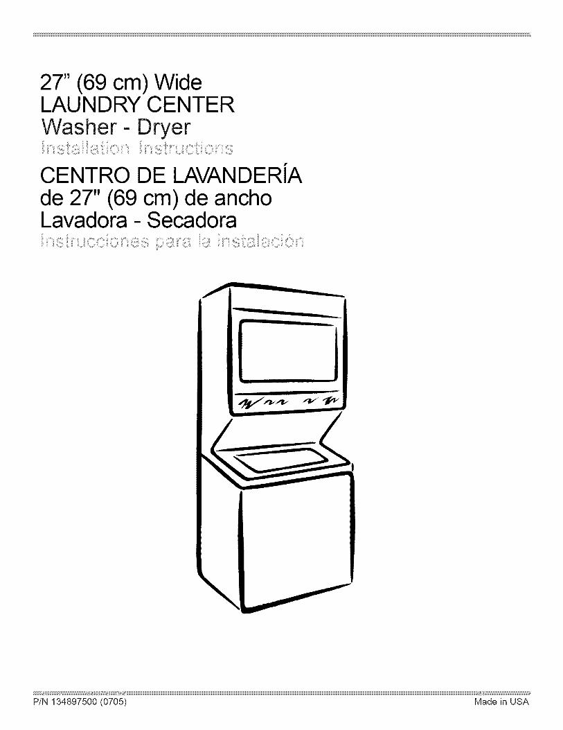
27" (69 cm) WideLAUNDRY CENTERWasher- Dryer
CENTRO DE LAVANDERiAde 27" (69 cm) de anchoLavadora - Secadora
iii
\

Table Of ContentsSUBJECT PAGE
Pre-lnstallation Requirements ........................................................................................................ 3Electrical Requirements ................................................................................................................. 3Water Supply Requirements ............................................................................................................ 3
Drain Requirements ...................................................................................................................... 3Exhaust System Requirements ................................................................................................... 4
Gas Supply Requirements ............................................................................................................. 5Location ................................................................................................................................. 5
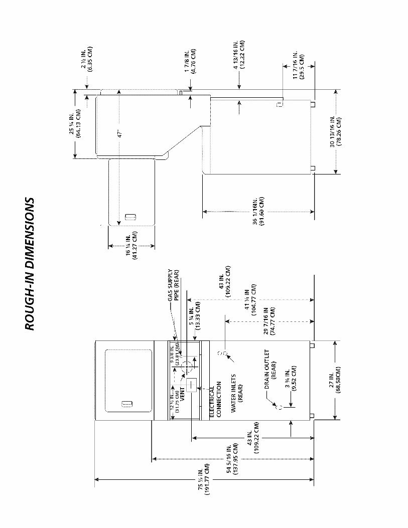
Rough-In Dimensions ..................................................................................................................... 6Mobile Home Installation .............................................................................................................. 7
Unpacking ........................................................................................................................ 7Electrical Installation ..................................................................................................................... 8
Grounding Requirements ................................................................................................................ 83 & 4-Wire Connections .................................................................................................................. 9Installation ................................................................................................................................. 10-11
Replacement Parts ..................................................................................................................... 11
Espahol ...................................................................................................................................... 12-20
Laundry Center SafetyBefore beginning installation, carefully read these instructions. This will simplify the installation
and ensure the laundry center is installed correctly and safely. Leave these instructions near thelaundry center after installation for future reference.
NOTE: The electrical service to the laundry center must conform with local codes and ordinances and thelatest edition of the National Electrical Code, ANSI/NFPA 70, or in Canada, the Canadian Electrical Code,CSA C22.1
NOTE: The gas service to the laundry center must conform with local codes and ordinances and the latestedition of the National Fuel Gas Code ANSI Z223.1/NFPA 54, or in Canada, the Canadian Natural Gas and
Propane Installation Code, CSA B149.1.
NOTE: The laundry center is designed under ANSI Z21.5.1 or ANSI/UL 2158- CAN/CSA C22.2 No. 112
(latest edition) for HOME USE only. This laundry center is not recommended for commercial applicationssuch as restaurants or beauty salons, etc.
For your safety the information in this manual must be followed to minimize the risk of
fire or explosion or to prevent property damage, personal injury or loss of life.
- Do not store or use gasoline or other flammable vapors and liquid in the vicinity of this or anyother appliance.
- WHAT TO DO IF YOU SMELL GAS
o Do not try to light any appliance.Do not touch any electrical switch; do not use any phone in your building.
Clear the room, building or area of all occupants. Immediately call your gas supplier from aneighbor's phone.Follow the gas supplier's instructions.
If you cannot reach your gas supplier, call the fire department.Installation and service must be preformed by a qualified installer, service agency or the gas supplier.
2

I GASLaundry Center ]PRE-INSTALLATION REQUIREMENTSTools and Materials Required for Installation:1. Phillips head screwdriver.2. Channel-lock adjustable pliers.3. Carpenter's level.4. Flat or straight blade screwdriven5. Duct tape.6. Rigid or flexible metal 4 inch (10.16 cm) duct.7. Vent hood.
8. Pipe thread sealer (Gas).9. Ratchet with 3/8 inch (0.96 cm) socket.
ELECTRICAL REQUIREMENTS
ELECTRICLaundry Center ]
Circuit- Individual 30 amp branch circuit fused with 30 ampminimum time delay fuses or circuit breakers.
POWER SUPPLY- 3-wire or 4-wire, 240 volt, single phase, 60Hz, Alternating Current.
POWER SUPPLY CORD KIT- The laundry center MUST employa 3-condutor power supply cord NEMA 10-30 type SRDTratedat 240 volt AC minimum, 30 amp, with 3 open end spade lugconnectors with upturned ends or closed loop connector OR a4-condutor power supply cord NEMA 14-30 type SRDTor ST(asrequired) rated at 240 volt AC minimum, 30 amp, with 4 openend spade lug connectors with upturned ends or closed loopconnectors and marked for use with clothes dryers. If beinginstalled in a new branch circuit installation, manufactured(mobile) home, recreational vehicle or area which prohibitsgrounding through the neutral conductor, the laundry centerMUSTemploy a 4-condutor power supply cord NEMA 14- 30type SRDTor ST (as required) rated at 240 volt AC minimum,30 amp, with 4 open end spade lug connectors with upturnedends or closed loop connectors and marked for use with clothesdryers. See ELECTRICAL CONNECTIONS. (Canada - 4-wirepower supply cord is installed on laundry center).
OUTLET RECEPTACLE- NEMA 10-30R (3-wire) receptacle orNEMA 14- 30R (4-wire) receptacle to be located so the powersupply cord is accessiblewhen the laundry center is in an installedposition.
NEMA 10-30R NEMA 14-30R
CIRCUIT- Individual 15 amp minimum branch circuit fused witha time delay fuse or circuit breaker.POWER SUPPLY-3 wire, 120 volt single phase, 60 Hz,Alternating Current.POWER SUPPLY CORD -The gas laundry center is equippedwith a 120 volt 3-wire power cord.
NOTE: Do not underany circumstancesremove groundingprong from plug.
\Grounding Prong
WATER SUPPLY REQUIREMENTS
Hot and cold water faucets MUST be installed within 42 inches(106.68 cm) of your laundry center's water inlet. The faucetsMUSTbe 3/4 inch (1.9 cm) garden hose type so inlet hoses canbe connected. Water pressure MUST be between 10 and 120pounds per square inch (maximum unbalance pressure, hot vs.cold, 10 psi). Your water department can advise you of yourwater )ressure.
DRAIN REQUIREMENTS
1. Drain capable of eliminating 17 gals. per minute.2. A standpipe diameter of 11Ainches (3.18 cm) minimum.3. The standpipe height above the floor should be:
Minimum height: 33 inches (83.82 cm)Maximum height: 96 inches (244 cm)
t
96"Max,
---T--'- (244 cm)33" Min.(83.82cm)
NOTE: For installations requiring a longer drain hose, have aqualified technician install a longer hose, PIN 134049201,available from an authorized parts distributor. For drain systemsin the floor, install a siphon break kit, available from your localhardware store.

EXHAUST SYSTEM REQUIREMENTS
Use only 4 inch (10.16 cm) diameter (minimum)
flexible metal duct and approved vent hood which has a
swing-out damper(s) that opens when the dryer is in
operation. When the dryer stops, the damper(s)
automatically closes to prevent drafts and the entrance
of insects and rodents. To avoid restricting the outlet,
maintain a minimum of 12 inches (38.5 cm) clearance
between the vent hood and the ground or any otherobstruction.
The following are specific requirements forproper and safe operation of your laundry center. Failure tofollow these instructions can create excessive drying timesand fire hazards.
Do not use plastic flexible duct or metal foil toexhaust the dryer. Excessivelint can build up inside the exhaustsystem and create a fire hazard and restrict air flow. Restrictedair flow will increase drying times. If your present system ismade up of plastic duct or metal foil duct, _lace it with a rigidor flexible metal duct. Ensure the present duct is free of anylint prior to installing laundry center dryer duct.
iii i i i
INCORRECT
If the dryer is not exhausted outdoors somefine lint will be expelled into the laundry area. An accumulationof lint in any area of the home can create a health and firehazard. The dryer exhaust system MUST be exhausted tothe outside of the dwelling!
4
Do not allow combustible materials (forexample: clothinq,draperies/curtains, paper) to come in contactwith the exhaust system. The dryer MUSTNOT be exhaustedinto a chimney, a wall, a ceiling, or any concealed space of abuilding which can accumulate lint, resulting in a fire hazard.
Do not exceed the lenqth of duct pipe ornumber of elbows allowed in the" EXHAUST DUCT LENGTHS"chart. Lint car/accumulate in the system, plugging the systemand creating a fire hazard, as well as increasing drying times.
Do not screen the exhaust ends of the ventsystem, nor use any screws or rivets to assemble the exhaustsvstem. Lint can become caught in the screen, on the screws orrivets, clogging the exhaust system and creating a fire hazardas well as increasing drying times. Usean approved vent hoodto terminate the duct outdoors, and seal all joints with ducttape. All male duct pipe fittings MUSTbe installed downstreamwith the flow of air.
Explosion hazard. Do not install the laundrycenter where qasoline or other flammables are kept or stored.Ifthe laundry center is installed in a garage, it must be a minimumof 18 inches (45.7 cm) above the floor. Failure to do so canresult in death, explosion, fire or burns. The exhaust systemback pressure MUST not exceed 0.6 inches (1.52 cm) of watercolumn, measured with an inclined manometer at the point theexhaust connects to the dryer. The exhaust system should beinspected and cleaned a minimum of every two years withnormal usage. The more the dryer is used, the more often youshould check the exhaust system and vent hood for properoperation.
The maximum length of the exhaust system depends upon thetype of duct used, number of elbows and type of exhaust hood.
The maximum length for both rigid and flexible duct is shown inthe chart below.
Numberof 90 °Turns
EXHAUST DUCT LENGTHS
EXHAUST HOOD TYPE
\,
4"10.2C 4) Louvered
_25"
(6.
MAXIMUM LENGTH OF 4-INCH (10.2 CM)DIAMETER RIGID METAL DUCT
0
12
3
56 ft. (17.07 m)
46 ft. (14.02 m)
34ft. (10.36 m)
32 ft. (9.75 m)
42 ft.
36 ft.
28 ft.
18 ft.
MAXIMUM LENGTH OF 4-INCH (10.2 CM)DIAMETER FLEXIBLE METAL DUCT
(12.8 m)(10.97 m)<8.53 m>(5.48 m)
0
1
2
3
30ft. (9.14 m)22 ft. (6.7 m)16 ft. (4.88 m)10 ft. (3.05 m)
22 ft. (6.7 m)14ft. (4.27 m)10 ft. (3.05 m)5 ft. (1.5 m)

The laundry center may be exhausted four (4) ways with rearflush installation:1. Straight back2. Down (8 inch [20.32 cm] length of 4 inch [10.16 cm] rigid
duct and 1 elbow down)3. Left(8 inch [20.32 cm] length of 4 inch [10.16 cm] rigid
duct, 1 elbow down and 1 elbow left)4. Right (8 inch [20.32 cm] length of 4 inch [10.16 cm] rigid
duct, 1 elbow down and 1 elbow right)
To exhaust up, add an 11 inch (27.94 cm) length of standard 4inch (10.16 cm) diameter duct and a 90° elbow. The unit willbe positioned about 4Y2inches (11.43 cm) away from the wall(flush to wall exhausting may be done by going below the dryerthen sideways).An exhaust hood positionedto line up with the dryerexhaust can be installeddirectly through the outsidewall. To exhaust to the sideor down, add an 8 inch(20.32 cm) length of standard4 inch (10.16 cm) diameterduct and a 90° elbow.
GAS SUPPLY REQUIREMENTS
1.Installation MUSTconform with local codes, or in the absenceof local codes, with the National Fuel Gas Code, ANSI Z223.1(latest edition) or in Canada, the current AN/CGA B149.
2.The gas supply line should be of 1/2 inch (1.27 cm) pipe.
3. If codes allow, flexible metal tubing may be used to connectyour dryer to the gas supply line. The tubing MUST beconstructed of stainless steel or plastic-coated brass.
4. The gas supply line MUST have an individual shutoff valve.
5.A 1/8 inch (0.32 cm) N. R T. plugged tapping, accessible fortest gage connection, MUST be installed immediatelyupstream of the gas supply connection to the dryer.
6.The dryer and its individual shutoff valve MUST bedisconnected from the gas supply piping system during anypressure testing of the gas supply piping system at testpressures equal to or less than 1/2 psig (3.45 kPa).
7.The dryer MUSTbe isolated from the gas supply piping systemby closing its individual manual shutoff valve during anypressuretesting of the gas supply piping system at test pressuresequal to or less than 1/2 psig (3.45 kPa).
LOCATION OF YOUR LAUNDRY CENTER
DO NOT INSTALL YOUR LA UNDRY CENTER:1.In an area exposed to dripping water or outside weather conditions.2.In an area where it will come in contact with curtains or drapes.3.On carpet. Floor MUSTbe solid with a maximum slope of 1 inch (2.54 cm).
INSTALLATION IN RECESSOR CLOSET1.A laundry center installed in a bedroom, bathroom, recess or closet, MUSTbe exhausted outdoors.2.No other fuel burning appliance shall be installed in the same closet as the Gas laundry center.3.Your laundry center needs the spacearound it for proper ventilation.
DO NOT INSTALL YOUR LAUNDRY CENTER IN A CLOSET WITH A SOLID DOOR.4.A mirfimum of 120 square inches (774.2 square cm) of opening, equally divided at the top and bottom of the door, is required.
Air openings are required to be unobstructed when a door is installed. A Iouvered door with equivalent air openings for the fulllength of the door is acceptable.
5.The following illustrations show minimum clearance dimensions and air openings for proper operation in a recess or closet
' 60 SQ. IN.
(387.1 SQ. CM)
Closet Door
installation.0 IN.
(0 CM)_
60 SQ. IN.(387.1 SQ. CM)
DRYER
60 SQ. IN.(387.1 SQ. CM)
T
WAS.E.60 SQ. IN.
(387.1 SQ. CM)
m_
_U
_S
L--J
m_
_uII
o
Zt_m_

MOBILE HOME INSTALLATION
1.Dryer MUST be exhausted outside (outdoors, not beneath the mobilehome) using metal ducting that will not support combustion. Metalducting must be 4 inches (10.16 cm) in diameter with no obstructions.Rigid metal duct is preferred.
2.If dryer is exhausted through the floor and area beneath the mobilehome is enclosed, the exhaust system MUSTterminate outsidethe enclosure with the termination securely fastened to the mobilehome structure.
3. Refer to page 3 for other important venting requirements.
4.When installing a gas dryer into a mobile home, a provision must bemade for outside make up air. This provision is to be not lessthan twicethe area of the dryer exhaust outlet.
5. Installation MUSTconform to current Manufactured Home Construction& Safety Standard (which is a Federal Regulation Title 24 CFR-Part 32-80) or when such standard is not applicable, with American NationalStandard for Mobile Homes. In Canada, the CSA Z240 is applicable.
ii i
_iiiiiiiiiiiiiiiiiiiiiiiiiiiiiiiiiiiiiiiiiiiiiiiiiiiiiiiiiiiiiiiiiiiiiiiiiiiiiiiii
_1__ The laundry center is designed under ANSI Z 21.5.1for HOME USE only.
iiiiiiiiiiiiiiiiiiiiiiiiiiiiiiiiiiiiiiiiiiiiiiiiiiiiiiiiiiiiiiiiiiiiii
UNPACKING
1. Using the four shipping carton corner posts (two on eachside), carefully lay the laundry center on its left side andremove foam shipping base.
Excessive weight. Use two or more peopleto move Laundry Center.
2. Using a ratchet with 3/8 inch (0.96 cm) socket, remove themechanism shipping bolt and plastic spacer block from thecenter of the base.
NOTE: If the laundry center is to be transported at a laterdate, the tub blocking pad, shipping bolt, and plasticspacer block should be retained.
3. Return laundry center to an upright position.4. Remove:
(a) foam tub blocking pad.(b) foam shipping blocks from rear of unit.(c) tape from dryer door.(d) foam dryer support pads.(e) inlet hoses.(f) enclosure package.
5. From the back of the washer, remove the wire shippingclips securing the drain hose and power cord (if equipped).Plastic clamps secure the drain hose to the right side ofthe washer backsheet. These clamps form a standpipe toprevent water syphoning. DO NOT REMOVE THESECLAMPS.
6. Carefully move the laundry center to within 4 feet (1.22 m)of the final location to begin the installation.
PLASTIC SPACER
SHIPPINGBOLT
FOAMSHIPPINGPAD
(IF EQUIPPED)
DRAIN HOSE
CARTON CORNER POSTS

IELECTRICAL INSTALLATION
ALL ELECTRICLaundry Centers I_The following are specific requirements forproper and safe electrical installation of your laundry center.Failure to follow these instructions can create electrical shockand/or a fire hazard.
_This appliance MUST be properly qrounded.Electrical shock can result if the laundry center is not properlygrounded. Follow the instructions in this manual for propergrounding.
Do not use an extension cord with this
laundry center. Some extension cords are not designed towithstand the amounts of electrical current this laundry centerutilizes and can melt, creating electrical shock and/or fire hazard.Locate the laundry center within reach of the receptacle for thelength power cord to be purchased, allowing some slack in thecord. Refer to the pre-installation requirements in this manualfor the proper power cord to be purchased.
A U.L approved strain relief must be
installed onto power cord. If the strain relief is not attached, thecord can be pulled out of the laundry center and can be cut byany movement of the cord, resulting in electrical shock.
Do not use an aluminum wired receptaclewith a copper Wired power cord and plug (or vice versa). Achemical reaction occurs between copper and aluminum andcan cause electrical shorts.
The proper wiring and receptacle is a copper wired powercord with a copper wired receptacle OR aluminum wiredpower cord with an aluminum wired receptacle.
NOTE: Laundry centers operating on a 208 volt power supplywill have longer drying times than laundry centers operating ona 240 volt power supply.
GROUNDING REQUIREMENTS
i Non-CanadianELECTRICLaundryCenter l
Improper connection of the equipment
grounding conductor can result in a risk of electrical shock.Check with a licensed electrician if you are in doubt as to whetherthe appliance is properly grounded.
For a qrounded, cord-connected laundry center:1. The laundry center MUST be grounded. In the event of
malfunction or breakdown, grounding will reduce the risk ofelectrical shock by a path of least resistance for electricalcurrent.
. If your laundry center is equipped with a power supply cordhaving an equipment-grounding conductor and a groundingplug, the plug MUSTbe plugged into an appropriate, copperwired receptacle that is properly installed and grounded inaccordance with all local codes and ordinances. If in doubt,call a licensed electrician. Do not modify plug providedwith the appliance.
For a permanently connected laundry center:The laundry center MUST be connected to a grounded metal,permanent wiring system;or an equipment grounding conductorMUST be run with the circuit conductors and connected to theequipment-grounding terminal or lead on the appliance.
I Canadian ELECTRICLaundry Center 1_lmproper connection of the equipmentgrounding conductor can result in a risk of electrical shock.Check with a licensed electrician if you are in doubt as towhether the appliance is properly grounded.
For a grounded cord connected laundry center:1. The laundry center MUST be grounded. In the event of
malfunction or breakdown, grounding will reduce the risk ofelectrical shock by providing a path of least resistance forthe electrical current.
. Since your laundry center is equipped with a power supplycord having an equipment-grounding conductor and agrounding plug, the plug MUST be plugged into anappropriate outlet that is properly installed and grounded inaccordance with all codes and ordinances. If in doubt, call alicensed electrician.
ALL GAS Laundry Centers i1. The laundry center is equipped with a three-prong (grounding)
plug for your protection against shock hazard and should beplugged directly into a properly grounded three-prongreceptacle. Do not cut or remove the grounding prong fromthe plug.

ELECTRICAL CONNECTIONSFOR A 3-WIRE SYSTEM
i NON-G4NAD/ANEZECTR/CLaundry Center
1. Remove the screw securing theterminal block accesscover tothe rear panel and remove cover.
2. Install a U.L approved strain
relief connector in the entryhole on the back panel.
3. Insert a NEMA 10-30 Type SRDT,U.L approved power cord through the strain relief.
J
4. Attach the power cord neutral (central wire) conductor tothe silver colored center terminal on the terminal block.Tighten the screw securely.
SILVER TERMINALGREEN GROUND SCREW
l1.
.
.
ELECTRICAL CONNECTIONSFOR A 4-WIRE SYSTEM
NON-CANAD/ANELECTR/CLaundry Center
Remove the screw securing theterminal block access cover to therear panel and remove cover.
]
Install a U.L approved strain reliefconnector in the entry hole on theback panel.
Remove the neutral ground wire from the green groundscrew located above the termial block.
GREEN GROUND GREENSCREW CONDUCTOR SILVER TERMINAL
TERMINAL BLOCK
NEUTRALGROUNDWIRE
5. Attach the remaining two power cord outer conductors tothe outer brasscolored terminals on the terminal block.Tighten both screws securely.
6. Tighten the screws securing the cord restraint against thepower cord.
7. Reinstall the terminal accesscover.
NEUTRALGROUNDWIRE
RED _
BLACK
WHITE
STRAINRELIEF
MOUNTING
BRACKET,
POWER CORD
.
.
.
.
.
Insert a NEMA 14-30 Type STor SRDT,U.L approved powercord through the strain relief.
Attach the green power cord ground wire to the cabinetwith the green ground screw.
Attach the white (neutral) wire from the power cord and theneutral ground wire from the appliance harnessto the silvercolored center terminal on the terminal block. Tighten thescrew securely.
Attach the red and black wires from the power cord to theouter brass-colored terminals on the terminal block. Tightenboth screws securely.
Tighten the screws securing the cord restraint firmly againstthe power cord.
9. Reinstall the terminal block access cover.

INSTALLATION
1. Run some water from the hot and cold faucets to flush the c.water lines and remove particles that might clog up thewater valve screens, d.
2. Check inlet hosesto ensure the rubber washers are installedin each end.
3. Carefully connect the inlet hosesto the water valve (on theleft sideof the washer cabinet), tighten by hand, then tightenanother 2/3 turn with pliers.
_0 NOT CROSS THREAD OR0 VERTIGHTEN THESE CONNECTIONS.
4. Determine which water faucet is the HOT water faucet
and carefully connect the bottom inlet hose to the HOTwater faucet, tighten by hand, then tighten another 2/3turn with pliers. Carefully connect the top inlet hose to theCOLD water faucet, tighten by hand, then tighten another2/3 turn with pliers.
DO NOT CROSSTHREAD OR OVERTIGHTENTHESE CONNECTIONS.
Turn the water on and check for leaks at both connections.
5. Carefully move the laundry center to its final location.
6. To ensure the laundry center is level and solid on all fourlegs, tilt the laundry center forward so the rear legs are offthe ground. Gently set the laundry center back down toallow the rear legs to self adjust. Placea level on top of thewasher. Check it side to side, then front to back. Screwthe front leveling legs up or down to ensure the laundrycenter is resting solid on all four legs (no rocking of thelaundry center should exist).
NOTE: Keep the leg extension at a minimum to preventexcessive vibration.
.
Open the shutoff valve in the gas supply line.
Test all connections by brushing on a soapy water solution.NEVER TESTFOR GAS LEAKS WITH AN OPEN FLAME.
Form a " U " shape on the end of the drain hose with thehose pointed toward the drain. Place the formed end in alaundry tub or a standpipe and secure with a cable tieprovided in the enclosure package.
WATER WILLSYPHON FROM THEWASHER IF THEABOVEINSTRUCTIONS ARE NOT FOLLOWED.
Tie_
9. Remove the two (2) screws securing the dryer front accesspanel to the dryer cabinet. Lift the panel until the tabs canbe disengaged from the cabinet. Remove the panel and setaside.
7. GAS CONNECTION (Gaslaundry centers only)
a. Remove the shipping cap from gas pipe at the rear of thedryer.
NOTE: DO NOTconnect the laundry center to L.Rgas servicewithout converting the gasvalve. An L Rconversion kit mustbe installed by a qualified gas technician.
b. Connect a 1/2 inch (1.27 cm) I.D. semi-rigid or approvedpipe from the gas supply line to the 3/8 inch (0.96 cm) pipelocated on the back of the dryer. Use a 1/2 inch (1.27 cm)to 3/8 inch (0.96 cm) reducer for the connection. Apply anapproved thread sealer that is resistant to the corrosiveaction of liquefied gaseson all pipe connections.
Access
Panel
Screws

10. Connect the exhaust duct to outside duct work. Use ducttape to seal all joints.
11. Plug the power cord into a grounded outlet.
NOTE: Check to ensure the power is off at a circuit breaker/fuse box before plugging the power cord into an outlet.
12. Turn on the power at a circuit breaker/fuse box.
_Before operating the dryer, make
sure the dryer area is clear and free from
combustible materials, gasoline, and other
flammable vapors. Also see that nothing (such as
boxes, clothing, etc.) obstructs the flow ofcombustion and ventilation air.
13. Reinstall the dryer front access panel.
14. Run the washer and dryer though a cycle. Check for properoperation.
NOTE: On gas dryers, before the burner will light, it is
necessary for the gas line to be bled of air. If the burner
does not light within 45 seconds the first time the
dryer is turned on, the safety switch will shut the
burner off. If this happens, turn the timer to "OFF"
and wait 5 minutes before making another attempt to
light.
REPLACEMENT PARTS
If replacement parts are needed for your laundry center, contactthe source where you purchased your laundry centen
_ Destroy the carton, plastic bags, and metalband after the laundry center is unpacked. Children might usethem for play. Cartons covered with rugs, bedspreads, or plasticsheets can become airtight chambers causing suffocation. Placeall materials in a garbage container or make materials inaccessibleto children.
Label all wires prior to disconnection whenservicing controls. Wiring errors can cause improper anddangerous operation. Verify proper operation after servicing.
The instructions in this manual and all other
literature included with this laundry center are not meant tocover every possiblecondition and situation that may occur-.Goodsafe practice and caution MUST be applied when installing,operating and maintaining any appliance.
Maximum benefits and enjoyment are achieved whenall the Safety and Operating instructions are understoodand practiced as a routine with your laundry tasks.
15. If your laundry center does not operate, please review the"Avoid Service Checklist" located in your Owner's Guidebefore calling for service.
16. Placethese instructions ina location near the laundry centerfor future reference.
NOTE: A wiring diagram is located behind the dryer frontaccess panel.
10

InditeMA TERIA PA GINA
Requerimientosdeinstalaci6n preliminares ..............................................................................................................
Requerimientos el_ctricos .........................................................................................................................................Requerimientos del suministro de agua ...................................................................................................................
RequerimientosdedesagOe ..................................................................................................................................... 14Requerimientos del sistema de escape.............................................................................................................. 14-15Requerimientos del suministro de gas.................................................................................................................... 15Ubicaci6n ............................................................................................................................................................... 15
Dimensionespara la instalaci6n ............................................................................................................................. 16Instalaci6n en casasm6viles .................................................................................................................................. 17
Desembalaje.......................................................................................................................................................... 17Instalaci6n el_ctrica ............................................................................................................................................... 18
Requerimientos para la puesta a tierra .................................................................................................................. 18Conexi6nes el_ctricas- trifilaresy tetrafilares ................................................................................................... 18-19Instalaci0n ........................................................................................................................................................ 19-20
Repuestos .............................................................................................................................................................. 20
SEGURIDAD de CENTRO DE LAVANDARIA
Antes de comenzar la instalaci6n, lea cuidadosamente estas instrucciones. Esto simplificar_i la instalaci6n y
asegurar_i que la secadora se instale correctamente y de manera segura. Despu_s de completar la instalaci6n,coloque estas instrucciones cerca de la secadora para referencia futura.
NOTA: La alimentacion electrica para la secadora deber_qcumplir con los c6digos y reglamentos locales y conla 01tima edici6n del C6digo El_ctrico Nacional, ANSI/NFPA 70 o en Canada1 CSA C22.1 C6digo El_ctricoCanadiense, Parte 1.
NOTA: La alimentaci6n de gas para la secadora deber_i cumplir con los c6digos y reglamentos locales y con la01tima edici6n del C6digo Nacional para Gases Combustibles, ANSI Z223.1 o en Canada1CAN/CGA B149.12.
NOTA: La secadora est_qclasificada para USO DOMESTICO solamente, de acuerdo con la norma ANSI Z 21.5.1o ANSI/UL 2158 - CAN/CSA C22.2 No. 112 (las 01timas edici6nes). Esta secadora no se recomienda para usocommercial tal como en restaurantes, salones de belleza, etc.
Para su seguridad, siga las instrucciones contenidas en este manual a fin de reducir
a un minimo los riesgos de incendio o explosi6n o para evitar dahos materiales, lesiones personales o lamuerte.
- No almacene ni utilice gasolina u otros vapores y liquidos inflamables en la proximidad de _ste o de
cualquier otro artefacto el_ctrico.- QUE DEBE HACER S! PERCIBE OLOR A GAS
o No trate de encender ning0n artefacto el_ctrico.
No toque ning0n interruptor el_ctrico; no use ning0n tel_fono en su edificio.Haga salir a todos los ocupantes de la habitaci6n, del edificio y del lugar.
Llame a su proveedor de gas desde el teldono de un vecino. Siga las instrucciones del proveedor de
gas.Si no Iogra comunicarse con su proveedor de gas, Ilame al departamento de bomberos.
La instalaci6n y el servicio de mantenimiento debe de realizarlos un instalador calificado, la agenciade servicios o el proveedor de gas.
12

REQUERIMIENTOS DE iNS TALA CIONPRELIMINARES
Herramientas y materiales necesarios para la instalaciOn:I. Destornillador Phillips2. Alicates universales
3. Nivel de carpintero4. Destornillador para tornillo de cabeza plana o recta5. Cinta para ductos6. Ducto metalico rigido o flexible de 4" (10,2 cm)7. Caperuza de salida8. Sellador de tuberias (gas)9. LLavede tubo de 3/8 de pulgada (0,96 cm).
i Centre de/avander/a a GAS ]
CIRCUITO - Circuito individual derivado de 15 amp minimo, confusibles de retardo maximo o disyuntor.
ALIMENTACION ELECTRICA - Corriente alterna, monof_isica,60 Hz, 120 voltios, trifilar.
CORDONELECTRICO - La secadora est,1equipada con un cordon
electrico trifilar para 120 voltios.
NOTA: No saque por
ningun motivo la espiga
de puesta a tierra delenchufe.
REQUERIMIENTOS ELECTRICOS
I Centro de/avander/a ELLeCTRICAS i
CIRCUITO - Circuito derivado individual de 30 amperes, confusibles de 30 amp. del tipo de retardo minimo o disyuntores.
ALIMENTACIONELECTRICA - Corriente alterna, monofasica, 60Hz, 240 voltios; trifilar. (Canada- 240 voltios, monofasico, 60 Hz,corrienta alterna.)
CORDONEL_'CTRICO- Enla secadora seDEBEusar un cordon
elOctrico trifilar NEMA 10-30 tipo SRDTpara un voltaje nominalmin imo de240 voltios CA, 30 amp, con 3 conectores de horquillascon terminales abiertos y extremos dirigidos hacia arriba oconectores de anillo cerrado y marcados para uso en secadorasde ropa. Sisiendo instalado en una nueva instalaciOn del circuitodel rama, un vehiculo casero,recreacional (mOvil)manufacturadoo un area que prohiben el poner a tierra a traves del conductorneutral, seDEBEutilizar un cordon el_ctrico tetrafilar NEMA 14-30 tipo SRDTo ST(como sea necesario) para un voltaje nominalminimo de 240 voltios CA, 30 amp con 4 conectores de horquillascon terminales abiertos y extremos dirigidos hacia arriba oconectores de anillo cerrado y marcados para uso en secadorasde ropa.
VerCONEXiONES ELECTRICAS PARA SISTEMASTETRAFILARES.
(Canada - un cordon de suministro de energia de 4 alambres esinstalado en la secadora.)
TOMACORRIENTE- Eltomacorriente NEMA 10-30R debe estar
ubicado de manera que el cordon el_ctrico Ilegue hasta61cuandolasecadora est_ instalada. (Canada- receptaculo NEMA 14-30R.)
Espiga de I a tierra
REQUERIMENTOS DE SUMINISTRO DE AGUALasIlaves del agua caliente y fria DEBER,4Nser instaladas a nomas de 42 pulgadas (106,68 cm) de la entrada de agua de sucentro de lavanderia. La boca DEBEser de 3/4 pulgada (1,9cm) de diametro para que las mangueras de jardin puedan serconectadas. La presiOn de agua DEBE SERentre I 0 y 120lOs./pulg. 2 (la maxima diferencia entre la presiOn no equilibradadel agua caliente y fria es 101bs./pulg.2) Lacompaflia de aguapotable puede informarle sobre le presiOn del agua.
REQUERIMINTOS DE DESAGOE1. Capacidad para desaguar 17 galones por minuto.2. Diametro de la toma de agua: 1-1/4 pulgadas (3,16) como
minimo.3. Altura de la toma de agua sobre el piso:
Altura minima:33 pulgadas (83,82 cm)
1'33" Mi..
(83°82cm)
______k__
Altura maxima:96 pulgadas (244 cm)
t(244cm)
NEMA 10-30R NEMA 14-30R
13
NOTA : Paralasinstalacionesquerequieranuntubodemaslargo, pida a un tOcnico capacitado que instale un tubo maslargo, P/N 131461201, disponsible en los disribuidoresautorizados de piezasde repuesto. Para los sistemas de drenajeen el piso, instale un uego para detener la acciOn de sifOn,disponsible de una ferreteria local.

REQUERIMIENTOS DEL SISTEMA DE ESCAPEUtilice solamente ductos metalicos, rigidos o flexibles de 4"(10,2 cm) de diametro (minimo) y una caperuza de salida de usoaprobado, con registrosque giren haciaafuera quese abren cuandolasecadora seencuentra en funcionamiento. Cuando lasecadorase detiene, los registros se cierran automaticamente para evitarlascorrientes deaire yla entrada de insectosy roedores. Paraevitarobstruir la salida, mantenga una altura libre minima de 12 "(30,5cm) entre la caperuza de salida y el piso o entre cualquier otraobstrucci6n.
Los siguientes requerimientos sonespecificos para el fu ndonamiento correcto y seguro de susecadora. El incumplimiento de estas instrucciones puedecausar prolongacion excesiva del tiempo de secado y riesgosde incendio.
[] No use caho flexible de plastico ni papel metalizado paradesagotar la secadora.Sepuede acu mular un exceso de pelusasenel sistema de escape,crear un riesgo y obstruir el flujo de aire. Larestricci6n del flujo delaire prolongara el tiempo desecado. Sisu sistemade escapeactualtiene ductos de plastico o de laminas metalicas delgadas,reemplacelo con un ducto metalico ric ido oflexible.Aseguresede que los ductos existentes no tengan pelusas antes deinstalar el ducto de la secadora.
INCORRECT
F :i̧ 'i!i;i¸ii!iiiii!ii¸'i¸i¸iiiiiiiiiiiiiiiiiiiiiiiiiiiii_ii!i___i!ii_iiiiiiiiiiiiiiiiiiiiiiiiiiiiiiiiiiiiiiiiiiiiiiiiiiiii
CORRECT
\
CORRECT
[] Si el escape de la secadora no se diriqe al exterior, alqunaspelusas finas seran sopladas hacia el recinto donde se efectOa ellavado. Laacumulaci6n de pelusasen cualquier lugar de la casa,puede crear un peligro para la salud y un riesgo de incendio, iE/sistema de escape de la secadora DEBE estar dirigido haciael exterior de la vivienda! 14
[] No permita que los materiales combustibles (por ejemplo: laropa, cortinas/cortinajes, papel)tenqan contacto con los ductos.El escape de la secadora NO DEBE dirigirse hacia el interior deuna chimenea, haciauna pared, hacia elcielo rasoo haciacualquierotro espacio reducido del edificio, donde puede ocurriracumulaci6n de pelusasy constituir un peligro de incendio.
[] Excederla Iongitud del conducto riaido o los n0meros decodospermitidosen Iosdiaaramas "LARGOM,4,XIMO" puededisminuirla capacidad de exhaustaci6n del sistema. Obstruir el conductopuede provocar peligro de incendio, asicomo aumentar eltiempode secado.
[] No coloque un filtro en el extremo del escape del sistema niempleetomillos o remachespara ensamblar elsistemade escape.Laspelusaspodrian quedar atrapadas en losfiltros, enIostomilloso en los remaches, Io cual obstruiria elsistema de escape y creariaun riesgo de incendio, asi como tambi@n prolongaria el tiempode secado. Useuna caperuza de salida adecuada para elextremodel ducto que salgaalexterior de lavivienday selletodas lasjuntascon cinta adhesiva para ductos. Todos los accesorios de tuberiamachos, DEBEN ser instalados aguas abajo del flujo de aire.
Riesgo de explosiSn. No instale lasecadoradonde sequarda qasolina u otros materiales inflamables.Si lasecadorase instalaen ungarage, ella debe estar por Io menos18 pulgadas (45,7 cm) por encima del suelo. El incumplimientopuede resultar en la muerte, explosi6n, incendio, oquemaduras.1. LaconstrapresiOn del sistema de escape NO DEBE exceder
0,6 pulgadas (1,52 cm) de columna de agua, medida conun man6metro inclinado en la conexi6n del ducto de escapea la secadora.
2. Elsistema de escape debe ser inspeccionado y limpiadocada 2 ahos como minimo, bajo condiciones de usonormal. Mientrasm_sseuselasecadora, con mayorfrecuencia deben inspeccionarse el sistema de escape y lacaperuza de salida para verificar su buen funcionamiento.
El largo m_ximo sistema de escape depende del tipo de ductoque se usa, del nQmero de codos y del tipo de caperuza desalida. Enlatablasemuestraellargom_ximotantoparaductos flexibles como rigidos.
LARGO MAXIMO del Conducto Metalico
Rigido de 4" (10,2 cm) de DiametroTIPO DE CAPERUZA DE SALIDA
(Preferido)
(10,2 cm) (6.35 cm)
0 56 pies (17,07 m) 42 pies(12,8 m)
1 46 pies (14,02 m) 36 pies(10,97 m)
2 34 pies (10,36 m) 28 pies (8,53 m)
3 32 pies (9,75 m) 18 pies (5,48 m)LARGO MAXIMO del Conducto Metalico
Flexible de 4" (10,2 cm) de DiametroTIPODE CAPERUZA DE SALIDA
0 30 pies (9,14 m) 22 pies (5,49 m)
1 22pies (6,71 m) 14 pies (4,27 m)
2 16pie (4,88 m) 10 pies (3,05 m)
3 NO RECOMENDADO
Se puede colocar el ducto de escape de cuatro (4) manerasdistintas cuando el artefacto esta instalado con el fondo paralelocon la pared.I. Derecho hacia arras.2. Hacia abajo - ducto rigido, 8 pulgadas (20.32 cm) de Iongitud
y4 pulgadas (10,16 cm) de diametro & 1 ducto acodadohacia abajo.
3. Hacia la izquierda - ducto rigido, 8 pilgadas (20,32 cm) deIongitud y 4 pulgadas (10,16 cm) de diametro, 1 ductoacodado hacia abajo y un ducto acodado hacia la derecha.
4. Hacia la derecha - ducto rigido, 8 pulgadas (20,32 cm) deIongitud y 4 pulgadas (10,16 cm) de diametro, I ductoacodado hacia abajo y un ducto acodado hacia la derecha.
Para colocar el ducto de escape hacia arriba, aflada un ductode 11 pulgadas (27,94 cm) de Iongitud y de 4 pulgadas (10,16cm) de diametroy un ducto acodado de 90°. El artefactodebe estar a aproximadamente 4 1/2 pulgadas (11,43 cm) dela pared (Se puede colocar el ducto de escape paralelo con lapared pot colocarlo debajo de la secadora y dirigirlo hacia unlado).
Una caperuza de escapecolocada en forma tal que sealinie con el escape de lasecadora, puede set instaladadirectamente a trav_s de lapared exterior. Para colocar elducto de escape hacia arriba,aflada un ducto 11 pulgadas(27,94 cm) de Iongitud y 4pulgadas (10,16 cm) dey un ducto acodado de 90° . Elartefacto debe estar a
aproximadamente 4 I/2 pulgadas (11,43 cm) de la pared (sepuede colocar el ducto de escape paralelo con la paredcoloc_ndolo debajo de la secadora y dirigido hacia un lado).Para permitir el escape lateral o inferior, agregue un ducto de 8pulgadas (20,32 cm)de largo y 4 pulgadas (10,16 cm) de diametroest_ndar y un codo de 90° .
REQUERIMIENTOS DEL SUMINISTRO DE GAS
1. LainstalaciOn DEBE hacerse cumplir con los cOdigos locales oen ausencia de los mismos, de acuerdo con los estandares delNational Fuel Gas Code(COdigo Nacional para GasesCombustibles), ANSIZ223. I (la 01tima edition). ParaCanad&el Estandar CAN/CGA B149 que este en vigor.
2. Latuberia de alimentaciOn de gas debe set de I/2 pulgada(1,27 cm) de diametro.
3. Siesta permitido pot los codigos locales, se puede usartuberiade metal para conectar su secadora a la Iinea de suministro degas. Latubefia DEBE set fabricada de acero inoxidable o cobrerecubierto de plastico.
4. Latuberia dealimentaciOn de gasDEBEtener una Ilavedecierreindividual.
5. Una toma de 1/8 de pulgada (0,32 cm) N.RT. accesible paraconexiOn del manOmetro de prueba, DEBE set instaladainmediatamente aguas arriba de la conexiOn de la tuberia dealimentaciOn de gas a la secadora.
6. LasecadoraDEBEserdesconectada del sistema detuberiasdealimentaciOn de gas durante cualquier ensayo de presiOn delsistema detubefiasde alimentaciOn degas realizado a presionesde prueba de mas de 1/2 Ibs/pulg. 2(3,45 kPa).
7. La secadora DEBE aislarse del sistema de tuberias dealimentaciOn de gas durante cualquier ensayo de presiOn delsistema detubefiasde alimentaciOn de gas realizado en ensayosde presiOn iguales o inferiores a I/2 Ibs/pulg.2(3,45 kPa).
UBICA CION DE SU LA VANDER/A
NO INSTALE SU LAVANDERi:1. En un lugar donde puede haber goteos de agua o quede
expuesta alas inclemencias del tiempo.2. En un area donde pueda entrar en contacto con cortinas,
cortinajes o cualquier otra cosa que obstruya el flujo decombustion y ventilaciOn de aire.
3. Sobre alfombras. El piso DEBE set firme con un desnivelmaximo de 1 pulgada (2,54 cm).
INSTALA CION DENTRO DE UN NICHO OARMARIOI. Si lasecadora es instalada en un dormitorio, cuarto de baflo,
nicho o armario, el tubo del escapeDEBE ser instalado haciael exterior.
2. No se debe instalar ning0n otro artefacto que quemecombustible en el mismo armario en que esta instalada lasecadora a Gas.
3. La secadora necesita espacio a su alrededor para unaventilaciOn adecuada.
NO INSTALE LA SECADORA EN UN ARMARIO CON PUERTAMACIZA.
4. Serequiere corno minimo una abertura de 120 pulgadas cua-dradas (774,2 cm2), dividida equitativamente para la partesuperior e inferior de lapuerta. Cuando seinstala una puerta,es necesario proveer aberturas para el aire. Una puertaapersianada con aberturas para el aire en todo el largo de lapuerta es aceptable.
5. Lassiguientes ilustraci0nes muestran lasdimensi0nes minimasde espacio libre que debe existir para el buen funcionamientode lasecadora cuando se instala en un nicho o en un armario.
• 60 Pulg. _
(387.1 SQ. CM)
60 Pulg.2
(387.1 SQ. CM)
PU ERTA DEL ARIVIARIO
15
0 IN,(oCM)_
€i!iiii!!!!ii!ii!iii!iiiiii!iSI
ii_ _ii_

0
3
0
N_
_t
m U
,,..-_
t t
.L,_
Wt_ z_
_m
v
Z Am
L-J
v
Z_
Z_
v
_rZ,_'rn
16
O
t'N_
v

INSTALACION EN CASAS MOVILES
1. El tubo de escape de la secadora DEBEser instalado hacia elexterior (El escape debe colocarse en la parte exterior y nodebajo de la casam6vil.) Debe usarse ducto de metal que noseacombustible. Elducto de metal debetener cuatro pulgadas(10,16 era)de diametro y notener obstrucciones. Espreferibleusar ducto de metal que sea rigido.
2. Siel tubo de escape de lasecadora corre a trav_s del piso y elarea debajo de la casa m6vil es cerrada, el ducto de escapeDEBEterminar fuera del recinto, con elextremo final aseguradoen contra de la estructura de la casa m6vil.
3. AI instalar una secadora de gas en una casa m6vil, hay queinstalaruna provisi6n deairefresco suplementario. Laprovisi6ntiene que ser mas grande que dos veces elespacio del escapede la secadora.
4. Vea las paginas 2 y 3 para otros requisitos importantes deventilaci6n.
5. La instalaci6n DEBE cumplir con lasestandares aplicables dela Manufactured Home Construction & Safety Standard -Estandaresde SeguridadyConstrucciOndeCasasPrdabricadas(Titu Io24 CFR-Parte32-80 del Reglamento Federal)ocuandodichos estandares no sean aplicables, se deben complir conlos estandares de la American National Standard for MobileHomes (Estandares Nacionales Americanas para ViviendasMoviles). EnCanada se aplica el Estandar CSA Z240.
r_ _'' ' " EstasecadorahasidodisehadaPARA
USO DOMESTICO solamente, de acuerdo con la norma ANSIZ21.5.1.
DESEMBALA.IE
I. Utilizando las cuatro esquineras de embarque de la caja decarton (dos acada lado), coloque cuidadosamente lasecadorasobre el costado izquierdo y saque la base de espuma deembarque.
Peso excesivo. Se necesitan dos o maspersonas para mover la Lavadora.
2. Utilizando la Ilavede tubo de 3/8 de pulgada (0,96 cm) saqueel perno de embarque y el bloque espaciador de platico delcentro de la base.
NO TA: Si el centro de lavanderia via set transportada aottolugar a otra lugar posteriormente, conserve la espumade bloqueo de la tina, el perno de embarque y elespaciador de pl2stico.
3. Vuelva a colocar elcentro de lavanderia en la posiciOnvertical
4. Saque:(a) la pieza de espuma que bloquea la cavidad;(b) los bloques de espuma del embalaje de la parte posterior
del aparato;(c) la cinta de la puerta de la secadora;(d) las piezas de espuma para apoyar la seadora;(e) los tubos de entrada de agua;(f) el paquete.
5. Saque las pinzas metalicas del embalaje de la parte posteriorde la lavadora, que sujetan el tubo de drenaje y el cableel_ctrico. Hay abrazaderas de plastico que sujetan el tubode drenaje en labo derecho del resaldo de la lavadora.Estas abrazaderas forman una tubeda vertical para prevenirel sifonaje de agua. NO SAQUE ESTASABRAZADERAS.
6. Con cuidado, mueva el centro de lavanderia a cuatro pies(1,22 m) de su ubicaciOn definitiva para la instalaciOn final.
Bloque
espaciador de
Bloque de embarque
Perno de
embarque
Espuma
protectora
de embareque
(si viene el equipo)
Manguera de
desagOe
17
INSTALA C!6N ELL'CTRICA
[ TODA S/e s centre/avanderia ELECTRICAS ]
Los siguientes requerimientos sonespecificos para el funcionamien to correcto y seguro de susecadora. El incumplimiento de estas instrucciones puedecausar prolongaci6n excesiva del tiempo de secado y riesgosde incendio.
_._J__ Este artefacto DEBE set puesto a tierra demanera correcta. Si la lavanderia no esta debidamente puesta atierra sepuede producir un choque el_ctrico. Siga lasinstruccionesindicadas en este manual para lapuesta atierra enforma correcta.__ No use un cordon de extension con esta
lavanderia. Algunos cordones de extension no pueden soportar lacantidad de corriente el_ctrica que utiliza esta secadora y puedenfundirse, creando un peligro de choque el_ctrico y/o incendio.Ubique la lavanderia de manera que el cordon el_ctrico Ileguehastael tomacorriente que sevaausar,dejando un poco de holguraparaelcord0n. ConsultelosrequerimientosdeinstalaciOnpreliminares indicados eneste manual para elcordon el_ctrico quedebeseradquirido.
Sedebe instalar un anclaje aprobado pot elU.L para elcordon el_ctrico. Sino seutiliza un anclaje parasujetarel cordon el_ctrico, _ste puede salirse de la lavanderia y cortarsecon cualquier movimiento, resultando en un choque el_ctrico.
No utilice un tomacorriente con cables dealuminio con un cordon Vun enchufe de cobre (o viceversa). Seproduce una reacciOn quimica entre el cobre y el aluminio quepuede causar cortacircuitos. El cableado y temacorrienteapropiado es un cord6n el_ctrico equipado con conductoresde cobre con un tomacorriente con conductores de cobre.
NOTA: Las lavanderia que operan con un suministro de energiade 208 voltios usaran mas tiempo de secado que aquellas queoperan con un suministro de energia de 240 voltios.
REQUERIMIENTOS PARA LA PUESTA A TIERRA
i Centre de/avanderia ELt CTRICASNo can a dien ses JLaconexiOn indebida del conductor de puesta
atierra del equipo puede ocasionar un riesgo de choque el_ctrico.Consultecon un electricistaprofesionalsitiene alguna duda respectoa la puesta a tierra correcta del artefacto.Parauna secadora puesta atierra con cordon el_ctrico:I. La lavanderia DEBE set puesta a tierra. En caso de
malfuncionamiento ofalla, la puesta atierra reducira el riesgode choque el_ctrico proporcionando un trayecto de menorresistencia a la corriente electrica.
2. Sisu lavanderia estaequipada con un cordon elOctricoque poseeun conductor de puesta a tierra del equipo y un enchufe depuesta a tierra, dicho enchufe DEBE set conectado a untomacorriente adecuado, debidamente instalado y puesto atierra de acuerdo con todos loscOdigos y reglamentos locales.Si tiene alguna duda consulte aun electricista profesional. Nomodifique el enchufe proporcionado la apficacion.
18
Para una lavanderia conectada permanentemente:I. La lavanderia DEBEser conectada a un sistema de cableado
metalico permanente, puesto a tierra; o se debe instalar unconductor de puesta a tierra de equipo junto con losconductores del circuitoy conectarsealborne de puestaatierradel equipo o al cable del artefacto.
Centre de/avanderia ELffCTR/CAS canadienses 1
LaconexiOn indebida del conductor de puestaatierra del equipo puede ocasionar un riesgo dechoque el_ctrico.Consulte con un electricista profesional si tiene alguna dudarespecto a la puesta a tierra correcta del artefacto.
Parauna lavanderia puesta atierra, con cordon el_ctrico:1. La lavanderia DEBE set puesta a tierra.En caso de
malfuncionamiento o falla, lapuesta atierra reducira el riesgode choque el_ctrico proporcionando un trayecto de menorresistencia a la corriente el_ctrica.
Si su lavanderia esta equipada con un cordon el_ctrico queposee un conductor de puesta atierra del equipoy un enchufede puesta a tierra, dicho enchufe DEBE set conectado a untomacorriente adecuado, debidamente instalado y puesto atierra de acuerdo con todos los cOdigosy reglamentos locales.Sitienealguna duda consultea un electricista profesional. Nomedifique el enchufe propercienado la aplicaci6n.
l TODOS/os centres/avanderia GAS 1a
Esta lavenderia estaequipada con unench ufe detres espigas (depuesta atierra) para protecciOn en contra de choques el_ctricosy debe set conectada directamenta en un receptaculo para tresespigas el cual debe estar puesto atierra. No torte ni elimine laespiga de puesta a tierra de este enchufe.
J1.
CONEXI6NES ELECTRICAS PARAUN SISTEMA TRIFILAR
Centre de/avanderia ELECTR/CASNo canadienses
Saque los tornillos que sujetan la cubiertade acceso del tablero de homes y elsoportede montaje del anclaje del cordon, situadoen la esquinasuperior de la parte trasera dela secadora.
Instale un anclaje de cable aprobado pot elU.L, enel orificiodeentradadelcord0nel_ctrico en el soporte de montaje. Luegoapriete la tuerca con los dedos solamente.
Inserteuncordon el_ctricode 30 amp, NEMA10-30 Tipo SRDT,aprobado pot el U.L, atray,s del anclaje de cable.

4. Conecteelconductorneutrodelcordonel_ctrico(cablecentral)al bornecentralplateadodeltablerodebornes.Aprietefirmementeeltornillo.
BORNE PLATEADO
TORNILLOpuESTAAVERDE DE _ /
TIERRA
CABLE DE
PUESTAA
TIERRA
NEUTR0
5. Conecte los dos conductores externos restantes del cordonel_ctrico a los bornes bronceados externos del tablero debornes. Apriete firmemente lostornillos.
6. Apriete firmemente los torn illos del anclaje de cahie contra elcordon el_ctrico.
7. Coloque nuevamente la cubierta del tablero de bornes.
CONEXIONES EL_'CTRICASPARAUN SISTEMA TETRAFILAR
Centro de/avanderia ELECTR/CASNo canadiensesi
I. Saquelostornillos quesujetanla cubiertadeaccesodeltablerode bornesy el soporte de montaje del anclaje de cable situadoen la esquina superior en la parte trasera de la secadora.
2. Instale un anclaje de cable aprobado porel U.L, en elorificiode entrada del cordon elOctrico en el soporte de montaje.Luego apriete la tuerca con los dedos solamente.
TORNILLO VERDE
DE PUESTA
ATIERRA
CABLE DEPUESTAATIERRANEUTRB
ROJO "
CONDUCTOR VERDE DE CORDON
/ ELECTRICO BORNE PLATEADO
_ _ / TABLERO DE
3. Desconecte el cable de puesta a tierra neutral del tornilloverde de puesta atierra situado en laparte superior del tablerode bornes.
4. Inserte un cordon el_ctricote trafilar de 30 amp, NEMA 10-30Tipo STo SRDT,aprobado por el U.L, atray,s del anclaje decable.
5. Conecte el cable verde de puesta a tierra del cordon el_ctricoal gabinete mediante el tornillo verde de puesta atierra.
6. Conecte el conductor blanco (neutro) del cordon el_ctrico yel cable depuesta atierra neutro del mazo de cables delasecadora al borne plateado central del tablero de bornes.
7. Conecte los conductores rojo y negro del cordon el_ctrico alos bornes bronceados externos del tablero de bornes.
8. Apriete firmemente los tornillos del anclaje de cable contrael cordon el_ctrico.
9. Coloque nuevamente la cubierta del tablero de bornes.
INS TALA CION
I. Deje correr un poco de agua de las Ilaves de agua calientey fria para pilgar las Nneasy eliminar las particulas que pueden obstriur las rejillas de las %lvulas de agua.
2. Examine los tubos de entrada de agua para asegurarse deque las arandelas de caucho est_n instaladas en cada extremo.
3. Conecte con cuidado los tubos de entrada a la %lvula deagua (en el lado izquierdo de la lavadora), apriete a mano yluego apriete 2/3 d vuelta con unos alicates.
NO ESTROPEE LA5 ROSCAS NI APRIETEESTAS CONEXlONES EXCESIVAMENTE.
4. Determine cual de lasIlaves de agua es la de agua CALIENTEy conecte con cuidado el tubo inferior de entrada a la Ilavede agua CALENTE, apriete a mano y luego apriete 2/3 devuelta con unos alicates. Conecte con cuidado el tubo
superior de entrada a la Ilave de agua FRL4, apriete a manoy luege apriete 2/3 vuelta con unos alicates
NO ESTROPEE LAS ROSCAS N! APRIETE
ESTASCONEXlONES EXCESIVAMENTE. Abra la Ilave del aguay compuebe que no haya fugas en ninguna de lasdosconexiones.
5. Con cuidado, mueve el centro de lavanderia hasta suubicaci6n definitiva para instalaci6n final.
6. Para verificar si el centro de lavanderia esta nivelado yfirmemente asentado sobre lascuatro patas, inclinelo haciaadelante de modo que las patas posteriors queden enel aire. Luego vuelva a depositar cuidadosamente lam_quina para permitir que las patas posteriores se ajusten.Coloque un nivel de carpintero encima de la lavadora.Atornille o destornille los tornillos nivel de posteriores de lalavadoraseg0n sea necesario para que el centro de lavanderia quedefirmemente asentado sobre suscuatro patas (no debe habermovimiento de vaivOn.
NOTA: Mantenga las patas de nivelaciOn al minimo paraprevenir excesiva vibraciOn.

7. CONEXIONDELGAS(Secadoras a gas solamente)a. Saque la tapa de embarque de la tuberfa de gas de la
secadora situada en la parte trasera.
NOTA: NO conecte la lavanderia al suministro de propano, sinprimero instalar el juego de conversi6n a propano. Eljuego deconversi6n a propano debe ser instalado por un t@cnico de gascalificado.
b.Conecte una tuberfa semifigida de 1/2" (1,27 cm) D.I. ouna tubefia aprobada, desde la Ifnea de suministro degas a la tuberfa de 3/8" (0,96 cm) ubicada en la partetrasera de la secadora. Utilice un reductor de 1/2" (1,27cm)a 3/8" (0,96 cm)para laconexi6n. Aplique unsellador
de roscas de uso aprobado, resistente a la corrosi6n delos gases licuados, en todas las uniones de la tuberia.
c. Abra la valvula de cierre en la tuberia de suministro degas.
d. Pruebetodaslasconexionesaplicandocon unaescobilla una soluci6n jabonosa.
NUNCA UTILICE UNA LLAMA ABIERTA PARA DETECTARFUGASDE GAS.
8. Forme una "U" en el extremodeltubo de drenage co eltubo seflalando hacia el drenaje. Coloque el extremoformado del tubo de drenaje en lavadero or una tuberfavertical y fijelo con su sujetacables incluido en el paquete.
Atadura
alam_re -
SI NO SESIGUEN LAS INSTRUCCIONES ANTERIORE, ELSIFON SACARA ELA GUA DE LA LA VADORA.
9. Saque los dos (2) tomillos que sujen el panel de acceso delantero de la secadora al gabinete de la secadora. Levanteel panel hasta que las lengLietas se desenganchen delgabinet saque el panelycol6quelo a un lado.
Tornillos delpanle deacceso
10. Conecte elducto de escapealsistemade escapeexterior. Utilicecinta para obturar todas as uniones.
1I. Conecte elcord6n el@ctrico a un tomacorriente puesto atierra.
NOTA; AsegOrese de que la corriente est@desconectada en eldisyuntodcaja defusibles, antesdeconectar elcord6n el@ctricoen el tomacorriente.
12.Conecte la corriente en el disyuntodcaja de fusibles.
Antes de poner en funcionamiento lasecadora, asegOresede que no haya materiales combustibles,gasolina y otros vapores inflamables cerca de la secadora.AdemDsasegOresedeque no haya nada (tal como cajas,ropas,etc.) que obstruya el flujo del aire de combusti6n y ventilad6n.
13. Vuelva a instalar el panel de acceso delantero de la seadora
14. Haga funcionar la secadora durante un ciclo completo paracomprobar su buen funcionamiento.
NOTA: Enlas secadoras a gas, antes de encender el quemadores necesario purgar elaire de latu berfadel gas.Sielquemadorno enciende dentro de 45 segundos, cuando la secadora seenciende por primera vez, el interru ptor de seguridad apagarael quemador. Si@stosucede, gire el contador de tiempo a laposici6n "OFF" (apagado)y espere 5 minutos antesde intentarencender la secadora nuevamente.
15.Si su lavandefia no funciona, consulte la secci6n "Lista deControl de Averfas" que se encuentra en su Manual delUsuario, antes de Ilamar para obtener servicio.
16.Conserve estas instrucciones cerca de la secadora parareferen cia futu ra.
NOTA; Dentro de la consola de la secadora o debajo del panelsuperior se encuentra un diagrama del cableado.
PIEZAS DE RECAMB#O
Sinecesita obtener piezasde recambio para su secadora, p6ngaseen contacto con el distribuidor donde compr6 su secadora.
Cuando sereparan los controles, marque todoslos cables con etiquetas antes dedesconectarlos. Cualquier errorde cableado puede causar una operaci6n inadecuada y peligrosa.Aseg0 resede que lasecadora funcione adecuadamente despuesde reparada.
Destruya la caja de cart6n, las bolsas deplastico y la banda metalica despu@sde haber desempacado elcentro de lavandefia. Los niflos pueden ponerse ajugar con ellos.Las cajas de cart6n cubiertas con alfombras, colchas o pedazosde plastico pueden convertirse en camaras sin aire y causarasfixia.Elimine todos los materiales poni@ndolos en la basura o fueradel alcance de los niflos.
Lasinstrucciones incluidas en este manual
yen el resto de ladocumentaci6n que seentrega con la lavandefiano pueden cubrir todas lassituaciones o condiciones posibles quepuedan presentarse. Por Io tanto, se DEBEN seguir practicasseguras y tener cuidado cuando se instala cualquier artefactodom@stico.
Seobtiene el maximo de beneficiosy resultadoscuandotodaslas instrucciones de seguridad y defuncionamiento soncomprendidasy puestas en practicade forma rutinaria cadavez que se lava la ropa
20