2500 Chevy CK dropped spindle
5
2500-888 8/05 © A Division of KW AUTOMOTIVE North America, Inc. 1 INSTALLATION INSTRUCTIONS --1075 North Ave. Sanger, CA 93657-3539 local: 559-875-0222 fax: 559-876-2259 toll free: 800-445-3767-- 2500 DROPPED FRONT SPINDLE CHEVROLET C / K and G.M.C. SIERRA 1500 / 2500 / 3500 Pick-Ups Congratulations! You were selective enough to choose a BELLTECH PRODUCT. We have spent many hours developing our line of products so that you will receive maximum performance with minimum difficulty during installation. Note: Confirm that all of the hardware listed in the parts list is in the kit. Do not begin installation if any part is missing. Read the instructions thoroughly before beginning this installation. Warning: DO NOT work under a vehicle supported by only a jack. Place support stands securely under the vehicle in the manufacturer’s specified locations unless otherwise instructed. Warning: DO NOT drive vehicle until all work has been completed and checked. Torque all hardware to values specified. Reminder: Proper use of safety equipment and eye/face/hand protection is absolutely necessary when using these tools to perform procedures! Note: It is very helpful to have an assistant available during installation. RECOMMENDED TOOLS: • Properly rated floor jack, support stands, and wheel chocks • Combination wrench set • Torque wrench: 0-75 lb ft. range • Ratcheting socket wrench and sockets set • Safety Glasses KIT INSTALLATION 1) Set the parking brake and block the rear wheels. 2) Raise the front of the vehicle and place floor stands under the lift points. Do not place the floor stands under the lower control arms because spring tension is needed to assist in breaking loose the ball joint studs. 3) Remove wheel and tire assembly. 4) Remove brake caliper. CAUTION: When the brake caliper is removed, do not allow it to hang unsupported from the brake hose. Support the caliper with a piece of wire to prevent damage to the brake line. 5) Remove tie rod end from knuckle. 6) Remove hub-disc assembly (Photo 1). 7) Remove the three bolts attaching splash shields to knuckle (Figure 1).
Transcript of 2500 Chevy CK dropped spindle

2500-888 8/05 © A Division of KW AUTOMOTIVE North America, Inc.
1
INSTALLATION INSTRUCTIONS
--1075 North Ave. Sanger, CA 93657-3539 local: 559-875-0222 fax: 559-876-2259 toll free: 800-445-3767--
2500 DROPPED FRONT SPINDLE
CHEVROLET C / K and G.M.C. SIERRA 1500 / 2500 / 3500 Pick-Ups
Congratulations! You were selective enough to choose a BELLTECH PRODUCT. We have spent
many hours developing our line of products so that you will receive maximum performance with minimum difficulty during installation.
Note: Confirm that all of the hardware listed in the parts list is in the kit. Do not begin installation if
any part is missing. Read the instructions thoroughly before beginning this installation. Warning: DO NOT work under a vehicle supported by only a jack. Place support stands securely under
the vehicle in the manufacturer’s specified locations unless otherwise instructed. Warning: DO NOT drive vehicle until all work has been completed and checked. Torque all hardware to
values specified. Reminder: Proper use of safety equipment and eye/face/hand protection is absolutely necessary when
using these tools to perform procedures! Note: It is very helpful to have an assistant available during installation. RECOMMENDED TOOLS:
• Properly rated floor jack, support stands, and wheel chocks
• Combination wrench set
• Torque wrench: 0-75 lb ft. range
• Ratcheting socket wrench and sockets set
• Safety Glasses
KIT INSTALLATION 1) Set the parking brake and block the rear wheels.
2) Raise the front of the vehicle and place floor stands under the lift points. Do not place the floor stands under the lower control arms because spring tension is needed to assist in breaking loose the ball joint studs.
3) Remove wheel and tire assembly.
4) Remove brake caliper.
CAUTION: When the brake caliper is removed, do not allow it to hang unsupported from the brake hose. Support the caliper with a piece of wire to prevent damage to the brake line.
5) Remove tie rod end from knuckle.
6) Remove hub-disc assembly (Photo 1).
7) Remove the three bolts attaching splash shields to knuckle (Figure 1).
2500-888 8/05 © A Division of KW AUTOMOTIVE North America, Inc.
2
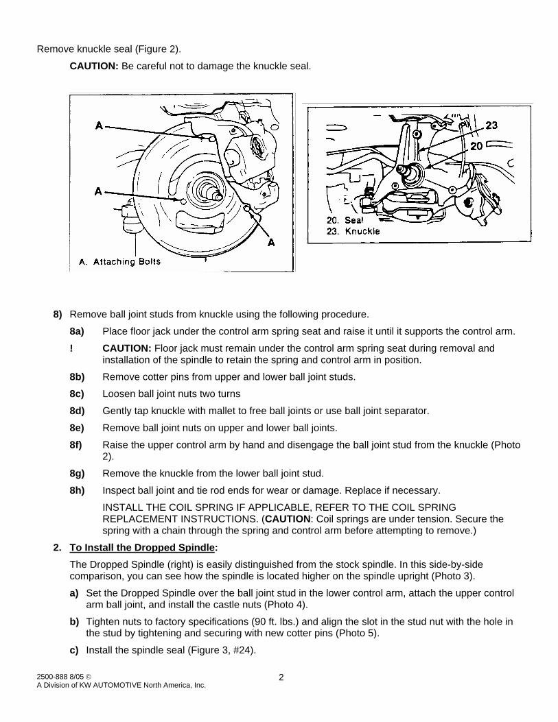
Remove knuckle seal (Figure 2).
CAUTION: Be careful not to damage the knuckle seal.
8) Remove ball joint studs from knuckle using the following procedure.
8a) Place floor jack under the control arm spring seat and raise it until it supports the control arm.
! CAUTION: Floor jack must remain under the control arm spring seat during removal and installation of the spindle to retain the spring and control arm in position.
8b) Remove cotter pins from upper and lower ball joint studs.
8c) Loosen ball joint nuts two turns
8d) Gently tap knuckle with mallet to free ball joints or use ball joint separator.
8e) Remove ball joint nuts on upper and lower ball joints.
8f) Raise the upper control arm by hand and disengage the ball joint stud from the knuckle (Photo 2).
8g) Remove the knuckle from the lower ball joint stud.
8h) Inspect ball joint and tie rod ends for wear or damage. Replace if necessary.
INSTALL THE COIL SPRING IF APPLICABLE, REFER TO THE COIL SPRING REPLACEMENT INSTRUCTIONS. (CAUTION: Coil springs are under tension. Secure the spring with a chain through the spring and control arm before attempting to remove.)
2. To Install the Dropped Spindle: The Dropped Spindle (right) is easily distinguished from the stock spindle. In this side-by-side comparison, you can see how the spindle is located higher on the spindle upright (Photo 3).
a) Set the Dropped Spindle over the ball joint stud in the lower control arm, attach the upper control arm ball joint, and install the castle nuts (Photo 4).
b) Tighten nuts to factory specifications (90 ft. lbs.) and align the slot in the stud nut with the hole in the stud by tightening and securing with new cotter pins (Photo 5).
c) Install the spindle seal (Figure 3, #24).

2500-888 8/05 © A Division of KW AUTOMOTIVE North America, Inc.
3
d) Install the splash shield (Photo 6).
e) Insert the tie rod into spindle.
f) Install the tie rod nut and tighten to factory specifications. Secure with new cotter pin.
g) Install the hub-disc assembly and adjust wheel bearings (Photo 7).
h) Install the disc brake caliper.
! CAUTION: The brake line elbow must be gently bent by hand to allow the brake line to clear the upper ball joint. Be careful not to damage the line or fittings. Do not use pliers or similar tools because they are more likely to cause damage.
i) Install wheel and tire assembly.
j) Remove floor stands and lower vehicle.
k) Rotate steering lock to lock under full weight of vehicle and full suspension travel to determine that there are no clearance problems before moving vehicle.
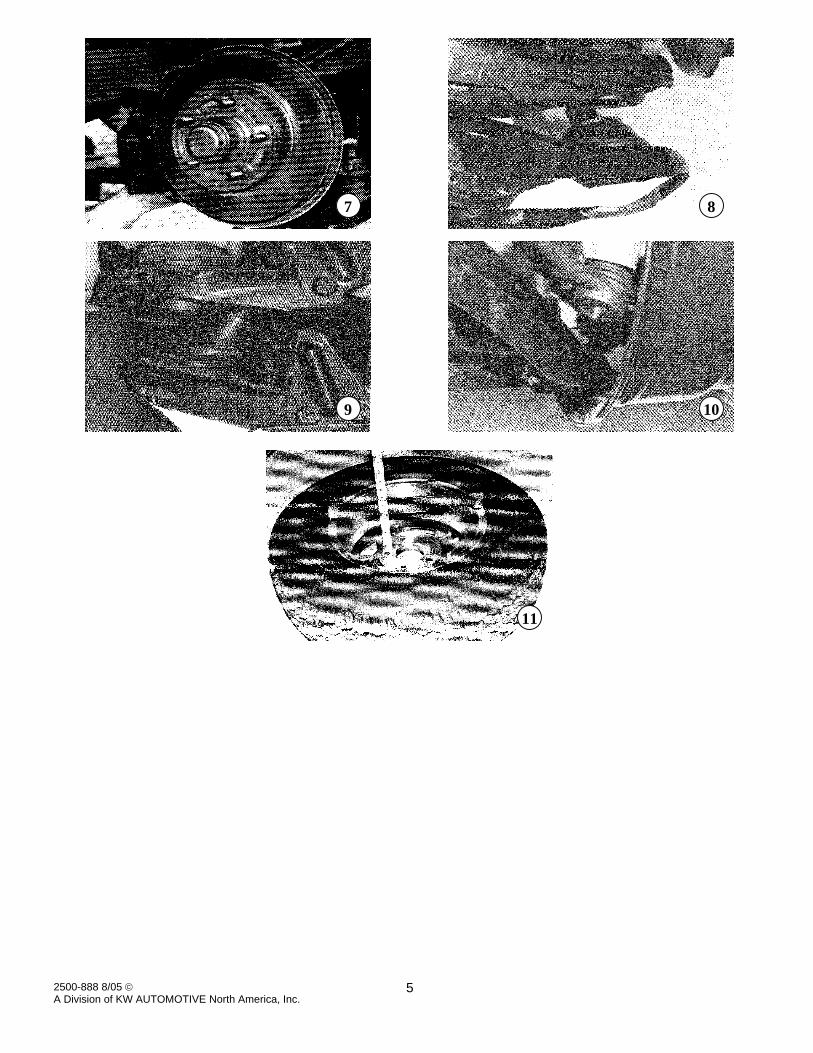
! CAUTION: Wheels with more than 3 ½” inches of backspacing, including the factory 7” inch steel and aluminum wheels, will interfere with the lower control arm which impairs the vehicle’s steering and are strongly cautioned against. This rim contact with the lower control arm is indicated in Photos 8 and 9. We recognize that it is common practice to trim the lower arm to eliminate the rim contact areas to provide clearance for wheels with more than 3 ½” inches of backspacing. We have not determined the affect of such modifications on the structural strength of the lower control arm nor what other risks attend such modifications. IMPORTANT NOTE: Any person modifying stock components does so at their own risk and does so against our recommendation. Additional due care must be exercised in the selection of tire and wheel combinations to determine that there absolutely is no wheel or tire clearance problems.
The white area of the lower control arm (Photo 8 and 9) indicates the interference area where wheel rim contact will occur when wheels with more than 3 ½” inches of backspacing are used. The installed lower control arm (top of pictures) has had its white area removed to provide clearance for non-recommended wheels. Please read entire caution under Step 11. IMPORTANT NOTE: We do not recommend or approve this modification.
2500-888 8/05 © A Division of KW AUTOMOTIVE North America, Inc.
4
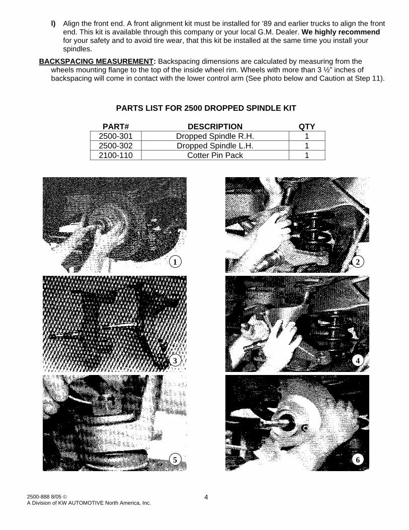
l) Align the front end. A front alignment kit must be installed for ’89 and earlier trucks to align the front end. This kit is available through this company or your local G.M. Dealer. We highly recommend for your safety and to avoid tire wear, that this kit be installed at the same time you install your spindles.
BACKSPACING MEASUREMENT: Backspacing dimensions are calculated by measuring from the wheels mounting flange to the top of the inside wheel rim. Wheels with more than 3 ½” inches of backspacing will come in contact with the lower control arm (See photo below and Caution at Step 11).
PARTS LIST FOR 2500 DROPPED SPINDLE KIT
PART# DESCRIPTION QTY 2500-301 Dropped Spindle R.H. 1 2500-302 Dropped Spindle L.H. 1 2100-110 Cotter Pin Pack 1
1
2
3
4
5
6
2500-888 8/05 © A Division of KW AUTOMOTIVE North America, Inc.
5
7
8
9
10
11