Chevy Silverado 1999-2005, Chevy Suburban 2000-2005,...
16
` Signal ® Mirror Installation Instructions Chevy Silverado 1999-2005, Chevy Suburban 2000-2005, Chevy Tahoe 2000-2005, Cadillac Escalade 2002-2005, Cadillac Escalade EXT 2002-2005, GMC Sierra 1999-2005, GMC Yukon XL 2000-2005, GMC Yukon Denali 2001-2005, Chevy Avalanche 2002-2005 THE safety accessory of the 21 st Century.™ P/N 210-0015-0 Rev. K4 (9-15-04), GG © 2003 Muth Mirror Systems, LLC. For 2003 plus model year, please go to page 5 ®
Transcript of Chevy Silverado 1999-2005, Chevy Suburban 2000-2005,...

`
Signal® Mirror Installation InstructionsChevy Silverado 1999-2005, Chevy Suburban 2000-2005, Chevy Tahoe 2000-2005, Cadillac Escalade 2002-2005, Cadillac Escalade EXT 2002-2005, GMC Sierra 1999-2005, GMC Yukon XL 2000-2005, GMC Yukon Denali 2001-2005, Chevy Avalanche 2002-2005
THE safety accessory of the 21st Century.™ P/N 210-0015-0 Rev. K4 (9-15-04), GG © 2003 Muth Mirror Systems, LLC.
For 2003 plus model year, please go to page 5
®

INCLUDED ITEMS: 1 left and 1 right Signal® mirror 1 left and 1 right wire harness 2 wire taps 2 ring connectors 1 instruction manual REQUIRED TOOLS: Ratchet with extension or ratcheting screwdriver 10mm socket 7mm socket 8mm socket Small slotted screwdriver Medium Philips screwdriver Needle nose pliers Small pry bar, Heater Gun Gopher wire Electrical tape Wire crimper and stripper Multimeter Sturdy gloves Safety glasses or goggles
PROBLEMS OR QUESTIONS?
Technical Assistance is available by calling Muth Mirror Systems Technicians at:
1-800-844-6616
Monday through Friday
Between 8:00 a.m. and 5:00 p.m. CST
Or through the Muth web site: www.muthco.com
Or via E-mail: [email protected]
Please read instructions prior to installation.
Note: Professional Installation Recommended Warranty does not cover damage to the vehicle or mirror housing due to improper installation. The
following installation instructions are to be considered as a guide only. Door removal procedures, indicator wire color and location may have changed since publication of these instructions. The installer
is responsible for any damage that may occur during installation.
Mirror Housing Removal
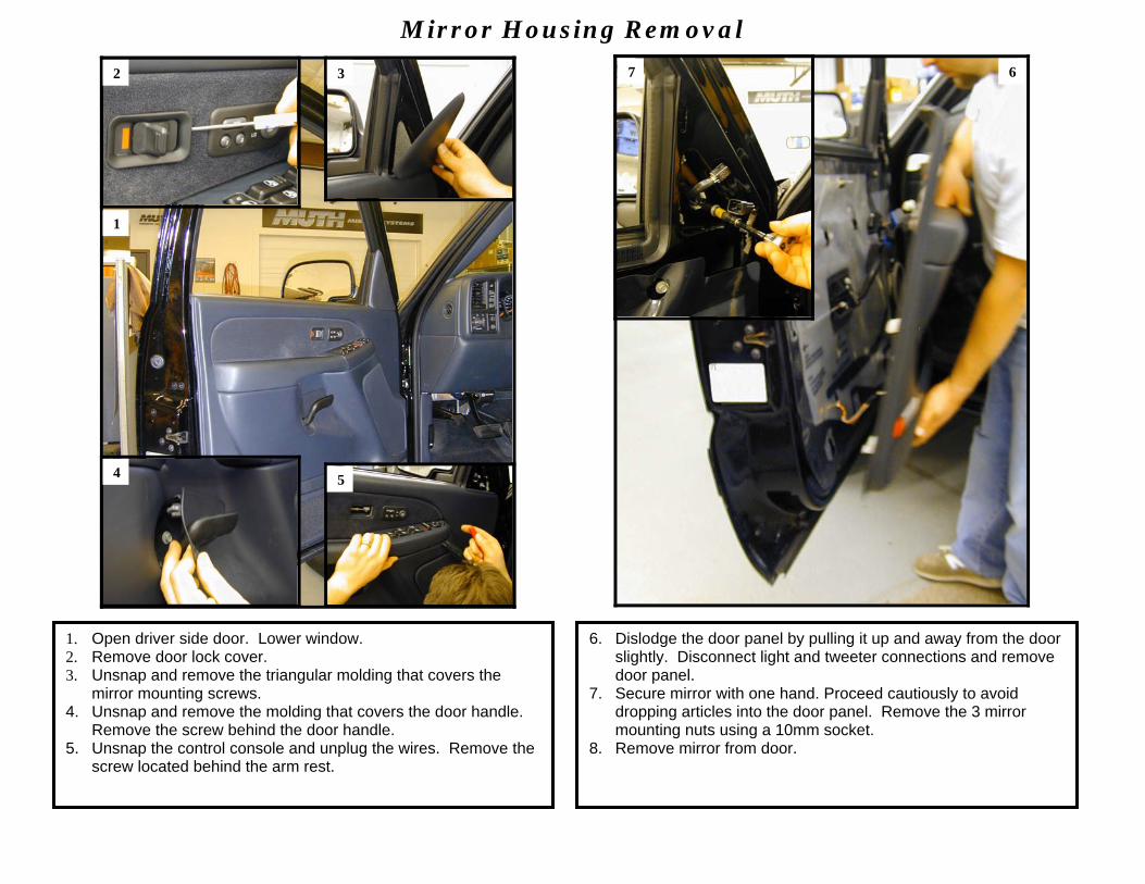
1. Open driver side door. Lower window. 2. Remove door lock cover. 3. Unsnap and remove the triangular molding that covers the
mirror mounting screws. 4. Unsnap and remove the molding that covers the door handle.
Remove the screw behind the door handle. 5. Unsnap the control console and unplug the wires. Remove the
screw located behind the arm rest.
1
2 3
4 5
6. Dislodge the door panel by pulling it up and away from the door slightly. Disconnect light and tweeter connections and remove door panel.
7. Secure mirror with one hand. Proceed cautiously to avoid dropping articles into the door panel. Remove the 3 mirror mounting nuts using a 10mm socket.
8. Remove mirror from door.
7 6

Mirror Replacement
Caution: Safety glasses and sturdy gloves are recommended for the following steps. 9. Place the mirror housing on a clean level surface. Push on the
outer edge of the mirror to manually pivot it fully outward so a flat head screwdriver can be inserted under its inner edge between the backplate and motor actuator. Gently twist and pull on the screwdriver until backplate dislodges from motor actuator. Repeat the process by moving the screwdriver around until backplate unsnaps from motor actuator. NOTE: If you have heated mirrors, disconnect the heater wires from the heater terminals. The polarity on the heater terminals is reversible so it is not necessary to label the terminals. Remove OE mirror from mirror housing.
- 2 -
9
10. Remove the rubber insulation on the mirror mounting frame to expose the wire routing passage. Locate the correct Signal® mirror harness (short for driver side and long for passenger side). Slide the end with no connector through the routing passage (from the inside of the mirror housing) and through the hole in the rubber insulation. Attach the rubber insulation to the mirror mounting frame. Pull the harness through leaving about 6 inches of slack in the harness near the motor pack.
10
Mirror Replacement Continues
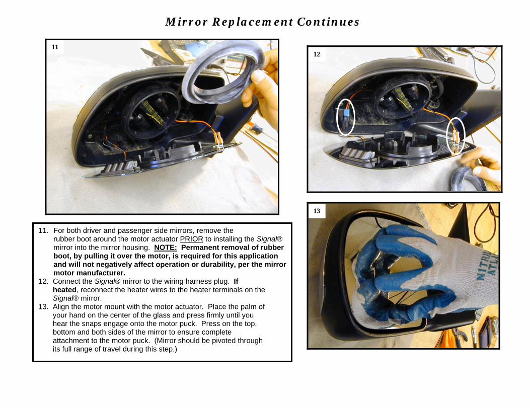
11. For both driver and passenger side mirrors, remove the rubber boot around the motor actuator PRIOR to installing the Signal® mirror into the mirror housing. NOTE: Permanent removal of rubber boot, by pulling it over the motor, is required for this application and will not negatively affect operation or durability, per the mirror motor manufacturer.
12. Connect the Signal® mirror to the wiring harness plug. If heated, reconnect the heater wires to the heater terminals on the Signal® mirror. 13. Align the motor mount with the motor actuator. Place the palm of your hand on the center of the glass and press firmly until you hear the snaps engage onto the motor puck. Press on the top, bottom and both sides of the mirror to ensure complete attachment to the motor puck. (Mirror should be pivoted through its full range of travel during this step.)
11
13
12
Mirror Housing Attachment
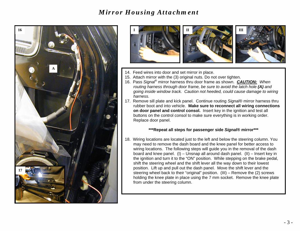
14. Feed wires into door and set mirror in place. 15. Attach mirror with the (3) original nuts. Do not over tighten. 16. Pass Signal® mirror harness thru door frame as shown. CAUTION: When
routing harness through door frame, be sure to avoid the latch hole (A) and going inside window track. Caution not heeded, could cause damage to wiring harness.
17. Remove sill plate and kick panel. Continue routing Signal® mirror harness thru rubber boot and into vehicle. Make sure to reconnect all wiring connections on door panel and control consol. Insert key in the ignition and test all buttons on the control consol to make sure everything is in working order. Replace door panel.
***Repeat all steps for passenger side Signal® mirror***
18. Wiring locations are located just to the left and below the steering column. You
may need to remove the dash board and the knee panel for better access to wiring locations. The following steps will guide you in the removal of the dash board and knee panel. (I) – Unsnap all around dash panel. (II) – Insert key in the ignition and turn it to the “ON” position. While stepping on the brake pedal, shift the steering wheel and the shift lever all the way down to their lowest position. Lift up and pull out the dash panel. Move the shift lever and the steering wheel back to their “original” position. (III) – Remove the (2) screws holding the knee plate in place using the 7 mm socket. Remove the knee plate from under the steering column.
- 3 -
16
A
17
I II III
Wiring
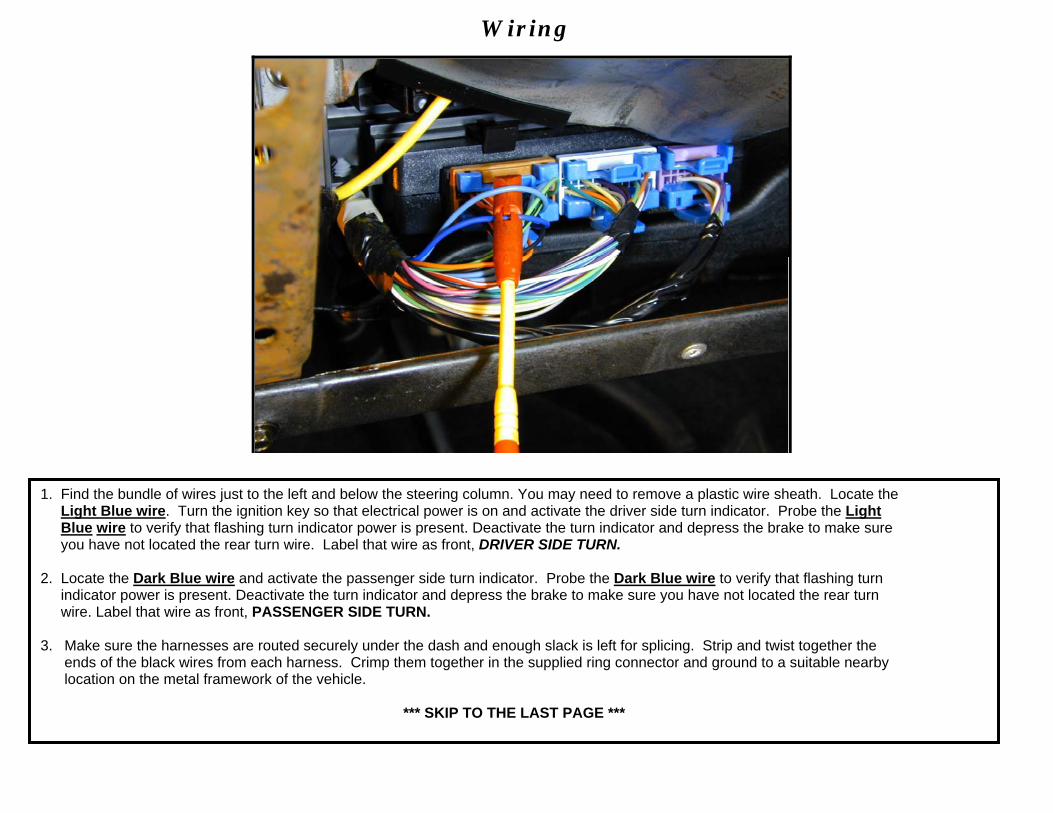
1. Find the bundle of wires just to the left and below the steering column. You may need to remove a plastic wire sheath. Locate the Light Blue wire. Turn the ignition key so that electrical power is on and activate the driver side turn indicator. Probe the Light Blue wire to verify that flashing turn indicator power is present. Deactivate the turn indicator and depress the brake to make sure you have not located the rear turn wire. Label that wire as front, DRIVER SIDE TURN. 2. Locate the Dark Blue wire and activate the passenger side turn indicator. Probe the Dark Blue wire to verify that flashing turn indicator power is present. Deactivate the turn indicator and depress the brake to make sure you have not located the rear turn wire. Label that wire as front, PASSENGER SIDE TURN. 3. Make sure the harnesses are routed securely under the dash and enough slack is left for splicing. Strip and twist together the ends of the black wires from each harness. Crimp them together in the supplied ring connector and ground to a suitable nearby location on the metal framework of the vehicle.
*** SKIP TO THE LAST PAGE ***

- 4 -
This page is intentionally left blank
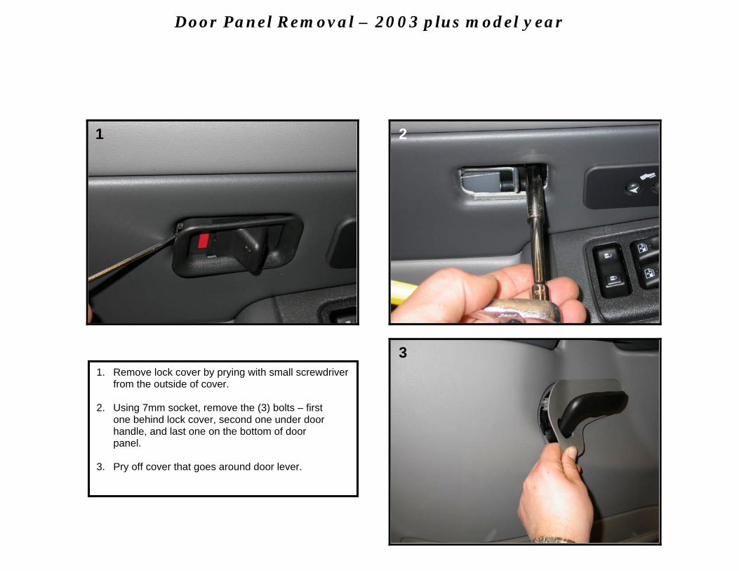
1. Remove lock cover by prying with small screwdriver from the outside of cover.
2. Using 7mm socket, remove the (3) bolts – first one behind lock cover, second one under door handle, and last one on the bottom of door panel. 3. Pry off cover that goes around door lever.
1 2
3
Door Panel Removal – 2003 plus model year
1
3
2
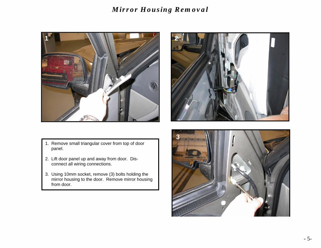
1. Remove small triangular cover from top of door panel. 2. Lift door panel up and away from door. Dis- connect all wiring connections. 3. Using 10mm socket, remove (3) bolts holding the mirror housing to the door. Remove mirror housing from door.
Mirror Housing Removal
- 5-
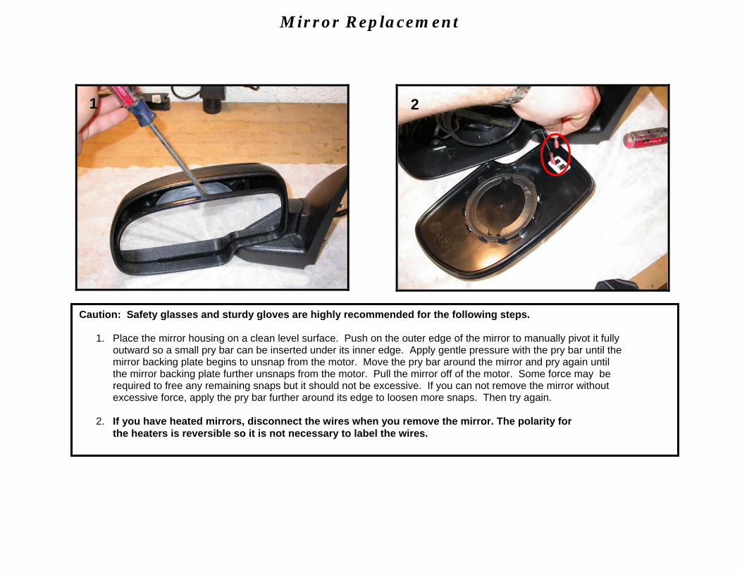
Caution: Safety glasses and sturdy gloves are highly recommended for the following steps.
1. Place the mirror housing on a clean level surface. Push on the outer edge of the mirror to manually pivot it fully outward so a small pry bar can be inserted under its inner edge. Apply gentle pressure with the pry bar until the mirror backing plate begins to unsnap from the motor. Move the pry bar around the mirror and pry again until the mirror backing plate further unsnaps from the motor. Pull the mirror off of the motor. Some force may be required to free any remaining snaps but it should not be excessive. If you can not remove the mirror without excessive force, apply the pry bar further around its edge to loosen more snaps. Then try again.
2. If you have heated mirrors, disconnect the wires when you remove the mirror. The polarity for the heaters is reversible so it is not necessary to label the wires.
Mirror Replacement
1 2
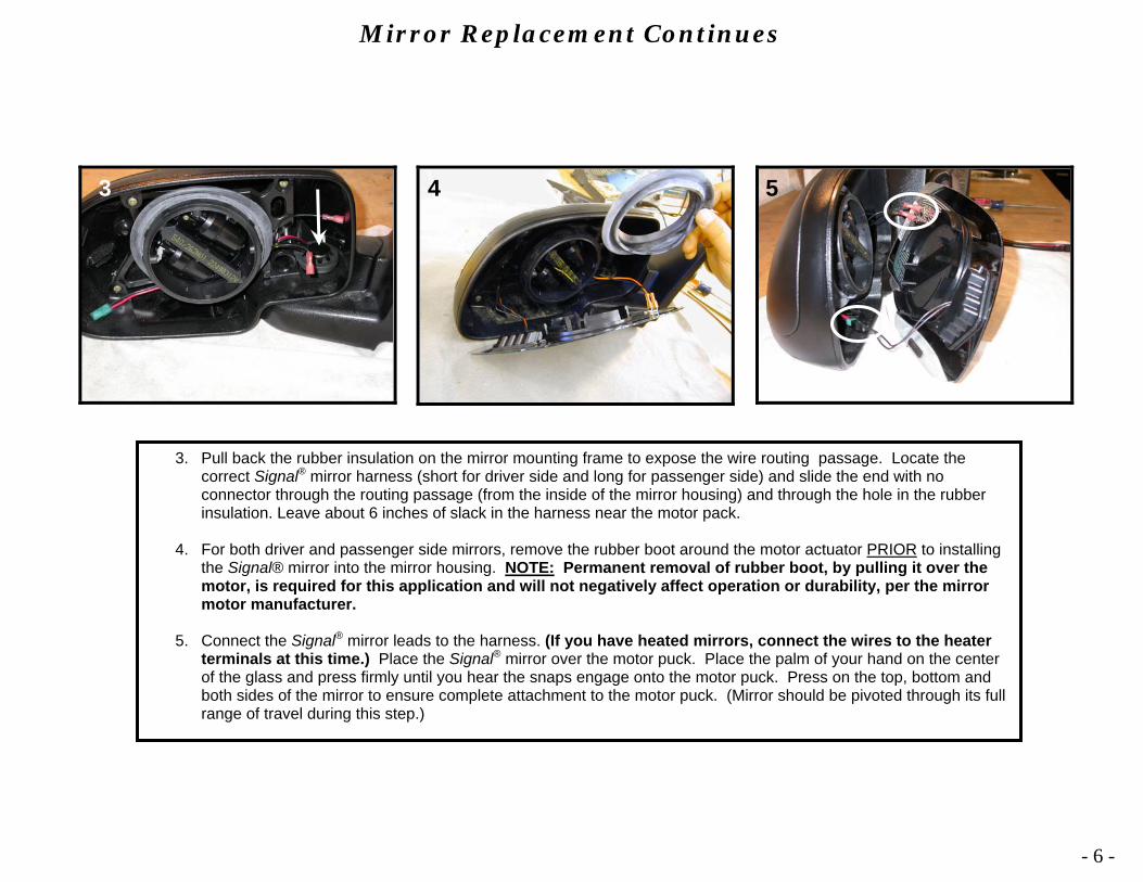
3. Pull back the rubber insulation on the mirror mounting frame to expose the wire routing passage. Locate the correct Signal® mirror harness (short for driver side and long for passenger side) and slide the end with no connector through the routing passage (from the inside of the mirror housing) and through the hole in the rubber insulation. Leave about 6 inches of slack in the harness near the motor pack.
4. For both driver and passenger side mirrors, remove the rubber boot around the motor actuator PRIOR to installing
the Signal® mirror into the mirror housing. NOTE: Permanent removal of rubber boot, by pulling it over the motor, is required for this application and will not negatively affect operation or durability, per the mirror motor manufacturer.
5. Connect the Signal® mirror leads to the harness. (If you have heated mirrors, connect the wires to the heater terminals at this time.) Place the Signal® mirror over the motor puck. Place the palm of your hand on the center of the glass and press firmly until you hear the snaps engage onto the motor puck. Press on the top, bottom and both sides of the mirror to ensure complete attachment to the motor puck. (Mirror should be pivoted through its full range of travel during this step.)
Mirror Replacement Continues
3 5
- 6 -
4
Mirror Housing Attachment
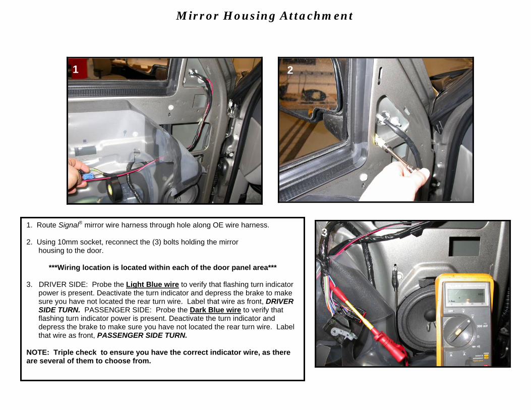
1. Route Signal® mirror wire harness through hole along OE wire harness. 2. Using 10mm socket, reconnect the (3) bolts holding the mirror housing to the door.
***Wiring location is located within each of the door panel area*** 3. DRIVER SIDE: Probe the Light Blue wire to verify that flashing turn indicator
power is present. Deactivate the turn indicator and depress the brake to make sure you have not located the rear turn wire. Label that wire as front, DRIVER SIDE TURN. PASSENGER SIDE: Probe the Dark Blue wire to verify that flashing turn indicator power is present. Deactivate the turn indicator and depress the brake to make sure you have not located the rear turn wire. Label that wire as front, PASSENGER SIDE TURN.
NOTE: Triple check to ensure you have the correct indicator wire, as there are several of them to choose from.
1 2
3
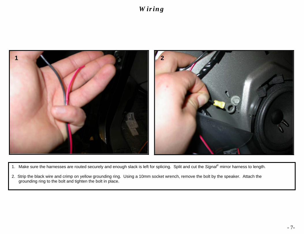
1. Make sure the harnesses are routed securely and enough slack is left for splicing. Split and cut the Signal® mirror harness to length.
2. Strip the black wire and crimp on yellow grounding ring. Using a 10mm socket wrench, remove the bolt by the speaker. Attach the grounding ring to the bolt and tighten the bolt in place.
Wiring
2 1
- 7-
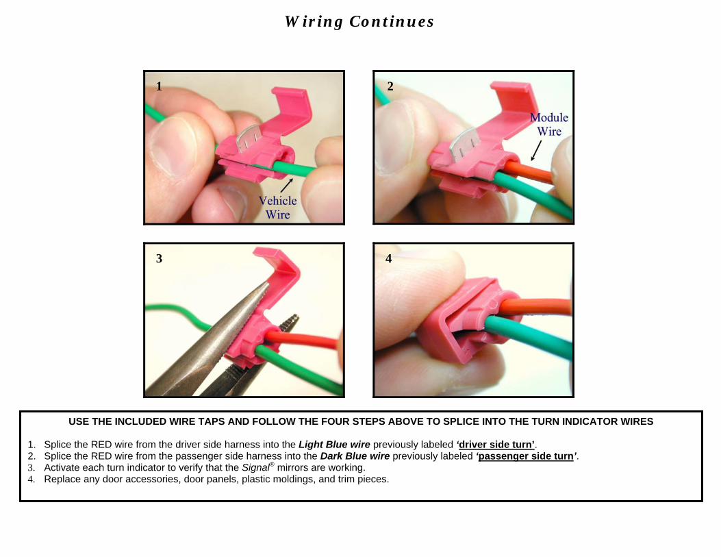
USE THE INCLUDED WIRE TAPS AND FOLLOW THE FOUR STEPS ABOVE TO SPLICE INTO THE TURN INDICATOR WIRES 1. Splice the RED wire from the driver side harness into the Light Blue wire previously labeled ‘driver side turn’. 2. Splice the RED wire from the passenger side harness into the Dark Blue wire previously labeled ‘passenger side turn’. 3. Activate each turn indicator to verify that the Signal® mirrors are working. 4. Replace any door accessories, door panels, plastic moldings, and trim pieces.
4 3
1 2
Wiring Continues

- 8-
This page is intentionally left blank