243 | P a g e International Standard Serial Number (ISSN ...ijupbs.com/Uploads/19....
17
243 | Page International Standard Serial Number (ISSN): 2319-8141 Full Text Available On www.ijupbs.com International Journal of Universal Pharmacy and Bio Sciences 6(2): March-April 2017 INTERNATIONAL JOURNAL OF UNIVERSAL PHARMACY AND BIO SCIENCES IMPACT FACTOR 2.96*** ICV 6.16*** Pharmaceutical Sciences RESEARCH ARTICLE …………!!! VALIDATION OF BUNG PROCESSOR Shridhar .M*, M.P Gowrav, Gangadharappa .H.V Department of Pharmaceutics (Pharmaceutical Quality Assurance) Jagadguru Sri Shivarathhreeswara University, Sri Shivarathreeshwara Nagara, Mysuru- 570015 Karnataka, India. KEYWORDS: Validation of autoclave, Vacuum leak test, Bowie- dick test, Heat distribution test, Heat penetration test. For Correspondence: Shridhar .M* Address: Department of Pharmaceutics (Pharmaceutical Quality Assurance) Jagadguru Sri Shivarathhreeswara University, Sri Shivarathreeshwara Nagara, Mysuru-570015 Karnataka, India. ABSTRACT In accordance with GMP, each pharmaceutical company should identify what qualification work is required to prove that the critical aspects of their particular operation are controlled. The key elements of a qualification and validation programme of a company should be clearly defined and documented. Qualification is the integral part of GMP and there is no effective QA program without qualification. Now-a-days it is mandatory to incorporate qualification activity for any system in the manufacturing premises for all pharmaceutical industries. The purpose of this study is to initially develop the sterilization process parameter for the porous load articles then implement the sterilization process for the porous articles. The process development included qualification of equipment and the articles. The autoclave cum bung processor which is used for the cleaning and sterilizing rubber stoppers, garments and machine parts. Initially installation qualification was done followed by performing the qualification of the equipment by performing Vacuum leak test, Bowie dick test, heat distribution test and heat penetration test. The equipment passes all tests and hence the equipment is suitable for sterilization purpose as it meets the predetermined specification and quality attributes. Hence the autoclave cum bung processor is considered to be qualified.
-
Upload
doankhuong -
Category
Documents
-
view
216 -
download
0
Transcript of 243 | P a g e International Standard Serial Number (ISSN ...ijupbs.com/Uploads/19....

243 | P a g e International Standard Serial Number (ISSN): 2319-8141
Full Text Available On www.ijupbs.com
International Journal of Universal Pharmacy and Bio Sciences 6(2): March-April 2017
INTERNATIONAL JOURNAL OF UNIVERSAL
PHARMACY AND BIO SCIENCES IMPACT FACTOR 2.96***
ICV 6.16***
Pharmaceutical Sciences RESEARCH ARTICLE …………!!!
VALIDATION OF BUNG PROCESSOR
Shridhar .M*, M.P Gowrav, Gangadharappa .H.V
Department of Pharmaceutics (Pharmaceutical Quality Assurance)
Jagadguru Sri Shivarathhreeswara University, Sri Shivarathreeshwara Nagara, Mysuru-
570015 Karnataka, India.
KEYWORDS:
Validation of autoclave,
Vacuum leak test, Bowie-
dick test, Heat
distribution test, Heat
penetration test.
For Correspondence:
Shridhar .M*
Address:
Department of
Pharmaceutics
(Pharmaceutical Quality
Assurance)
Jagadguru Sri
Shivarathhreeswara
University, Sri
Shivarathreeshwara
Nagara, Mysuru-570015
Karnataka, India.
ABSTRACT
In accordance with GMP, each pharmaceutical company should identify
what qualification work is required to prove that the critical aspects of
their particular operation are controlled. The key elements of a
qualification and validation programme of a company should be clearly
defined and documented. Qualification is the integral part of GMP and
there is no effective QA program without qualification. Now-a-days it is
mandatory to incorporate qualification activity for any system in the
manufacturing premises for all pharmaceutical industries. The purpose of
this study is to initially develop the sterilization process parameter for the
porous load articles then implement the sterilization process for the
porous articles. The process development included qualification of
equipment and the articles. The autoclave cum bung processor which is
used for the cleaning and sterilizing rubber stoppers, garments and
machine parts. Initially installation qualification was done followed by
performing the qualification of the equipment by performing Vacuum
leak test, Bowie dick test, heat distribution test and heat penetration test.
The equipment passes all tests and hence the equipment is suitable for
sterilization purpose as it meets the predetermined specification and
quality attributes. Hence the autoclave cum bung processor is considered
to be qualified.

244 | P a g e International Standard Serial Number (ISSN): 2319-8141
Full Text Available On www.ijupbs.com
INTRODUCTION:
An autoclave is a pressure chamber used to carry out industrial processes requiring elevated
temperature and pressure different to ambient air pressure. Autoclaves are used in medical
application to perform sterilization, and in the chemical industry to cure coatings, vulcanize rubber
and for hydrothermal synthesis1.
Autoclave was invented by Charles Chamber land in 18792. The name comes from Greek auto-
self, and Latin clavis - key, a self- locking device3.
The standard temperature and pressure of an autoclave Processes conducted at high temperatures
for short time periods are preferred over lower temperatures for longer times. Some standard
temperatures/pressures employed are 115 °C/10 psi, 121 °C/ 15 psi, and 132 °C/27psi. (psi=pounds
per square inch). In universal autoclave, autoclaving generally involves heating in saturated steam
under a pressure of approximately 15 psi, to achieve a chamber temperature of a least 121 °C (250
°F) but in other applications in industry, for example, other combinations of time and temperature
are sometimes used. Please note that after loading and starting the autoclave, the processing time is
measured after the autoclave reaches normal operating conditions of 121 °C (250 °F) and 15 psi
pressure, not simply from the time you push the "on" button4,5
.
There are four basic types of autoclaves. These types depend upon the method employed to remove
air from the sterilization chamber: Downward displacement autoclaves, Positive pressure
displacement autoclaves, Negative pressure displacement autoclaves and Triple vacuum autoclave.
The downward displacement autoclave is also referred to as a gravity displacement unit. This is
because of the method of air removal in the sterilization chamber. A pool of water in which an
element is immersed, turns to steam when heated. As steam is lighter than air, it forces the air in the
sterilization chamber downward and out through a drain hole. Once the temperature in the
sterilization chamber is sufficient, the drain hole is closed automatically and the sterilization
process begins.
A positive pressure displacement autoclave is an improvement upon the design of a downward
displacement unit. Steam is created in a second, separate chamber and held until the proper amount
to displace all of the air in the sterilization chamber is accumulated. The steam is then released into
the sterilization chamber in a pressurized blast, forcing the air out through the drain hole and
starting the sterilization process.
A negative pressure displacement autoclave is one of the most accurate types available. Once the
sterilization chamber door is closed, a vacuum pump removes the air. Steam is created in a second,
separate chamber. Once the air has been completely removed from the sterilization chamber, the

245 | P a g e International Standard Serial Number (ISSN): 2319-8141
Full Text Available On www.ijupbs.com
steam is then released into the sterilization chamber in a pressurized blast much like that of a
positive pressure displacement unit.
A triple vacuum autoclave is set up in a similar fashion to a negative pressure displacement unit in
that there is a vacuum pump to remove air from the sterilization chamber and steam is created in a
second, separate chamber or unit. The process begins by the vacuum removing the air, then a pulse
of steam. This is repeated three times, hence the name "triple vacuum" autoclave6.
The working process of autoclave
Basically, steam enters the chamber jacket, passes through an operating valve and enters the rear of
the chamber behind a baffle plate. It flows forward and down through the chamber and the load,
exiting at the front bottom. A pressure regulator maintains jacket and chamber pressure at a
minimum of 15 psi, the pressure required for steam to reach 121 °C (250 °F).
Overpressure protection is provided by a safety valve. The conditions inside are thermostatically
controlled so that heat (more steam) is applied until 121 °C is achieved, at which time the timer
starts, and the temperature is maintained for the selected time.
Figure 1: The temperature profile for a saturated steam vented cycle of autoclave
tₒ to tn is the time interval in the computation of the Fₒ value. F1 to Fn areas represent the lethal dose
provided to the material being treated. The shaded area under the curve obtained through
summation of F1 to Fn values represents the total Fₒ value. In the heating phase, saturated steam is
admitted into the chamber, displacing the cold air until the exposure temperature and corresponding
saturated steam pressure are attained. In the exposure phase, the sterilizing temperature is
maintained by saturated steam for the prescribed exposure time. The cooling phase can be achieved
by slow exhaust (for containers filled with liquids) or fast exhaust (for goods required to be dry
after sterilization). This phase is completed when the pressure reaches atmospheric pressure7.
246 | P a g e International Standard Serial Number (ISSN): 2319-8141
Full Text Available On www.ijupbs.com
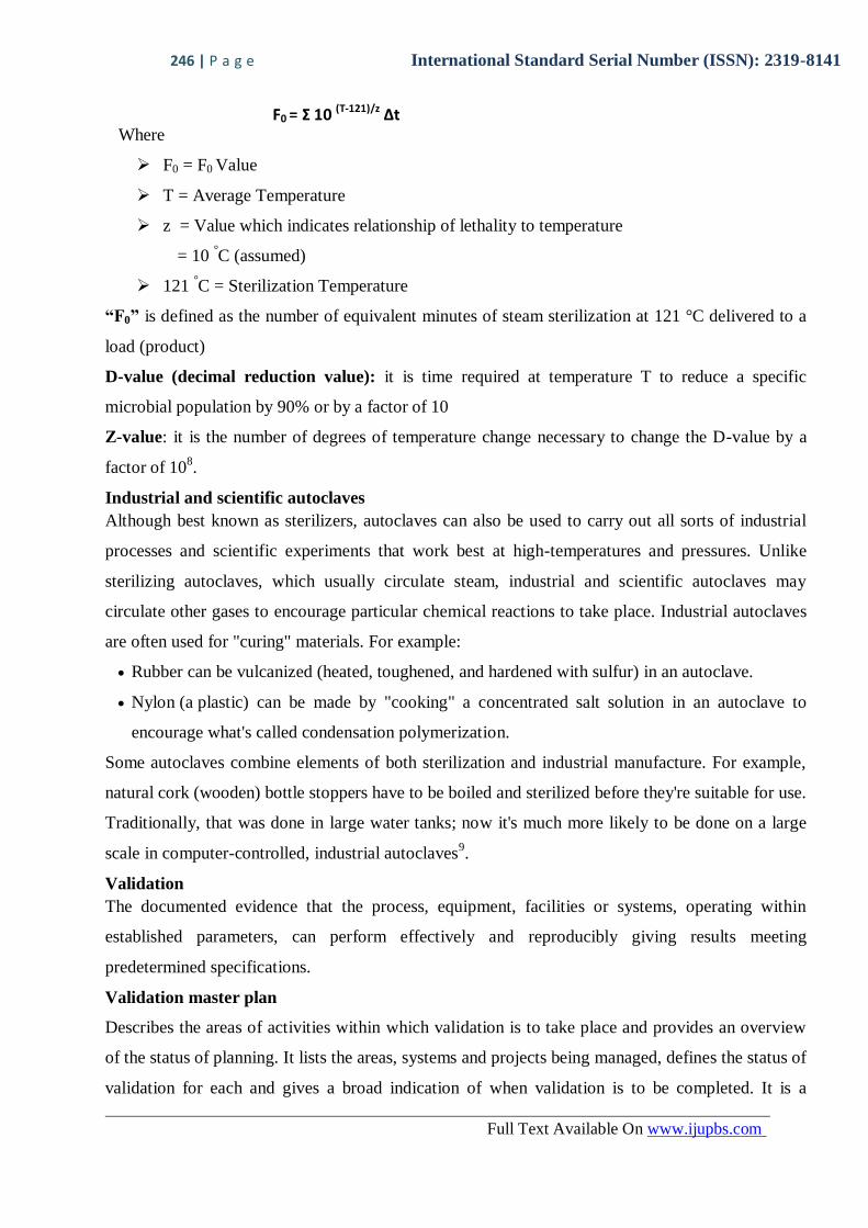
F0 = Σ 10 (T-121)/z ∆t Where
F0 = F0 Value
T = Average Temperature
z = Value which indicates relationship of lethality to temperature
= 10 °C (assumed)
121 °C = Sterilization Temperature
“F0” is defined as the number of equivalent minutes of steam sterilization at 121 °C delivered to a
load (product)
D-value (decimal reduction value): it is time required at temperature T to reduce a specific
microbial population by 90% or by a factor of 10
Z-value: it is the number of degrees of temperature change necessary to change the D-value by a
factor of 108.
Industrial and scientific autoclaves
Although best known as sterilizers, autoclaves can also be used to carry out all sorts of industrial
processes and scientific experiments that work best at high-temperatures and pressures. Unlike
sterilizing autoclaves, which usually circulate steam, industrial and scientific autoclaves may
circulate other gases to encourage particular chemical reactions to take place. Industrial autoclaves
are often used for "curing" materials. For example:
Rubber can be vulcanized (heated, toughened, and hardened with sulfur) in an autoclave.
Nylon (a plastic) can be made by "cooking" a concentrated salt solution in an autoclave to
encourage what's called condensation polymerization.
Some autoclaves combine elements of both sterilization and industrial manufacture. For example,
natural cork (wooden) bottle stoppers have to be boiled and sterilized before they're suitable for use.
Traditionally, that was done in large water tanks; now it's much more likely to be done on a large
scale in computer-controlled, industrial autoclaves9.
Validation
The documented evidence that the process, equipment, facilities or systems, operating within
established parameters, can perform effectively and reproducibly giving results meeting
predetermined specifications.
Validation master plan
Describes the areas of activities within which validation is to take place and provides an overview
of the status of planning. It lists the areas, systems and projects being managed, defines the status of
validation for each and gives a broad indication of when validation is to be completed. It is a

247 | P a g e International Standard Serial Number (ISSN): 2319-8141
Full Text Available On www.ijupbs.com
general plan and would normally cover all equipment and processes. It should include all systems
for which validation is planned.
Validation plan
Description of the validation activities, responsibilities and procedures. It describes specifically
how the validation is to be done and details responsibilities if the validation team.
Validation protocol
Outlines the objectives of validation of a specific equipment, testing protocol including elements
such as installation, operational and performance qualification and documentation.
Within the laboratory there should a validation policy which is a strategy document that clearly
defines what the validation process is and its purpose within the laboratory. The policy should make
a commitment to maintaining critical processes and systems in a valid state and should mention
applicable regulations, standards and guidelines that underpin the laboratory’s approach to
validation. The validation policy will specify what should be validated and how validation is
executed as defined in the validation master plan.
The validation master plan (VMP) is a quality management system document. It should be a
controlled document, approved by senior laboratory management and regularly reviewed and, if
necessary, revised in response to organizational and operational changes.
The VMP should be based on and refer to the validation policy. The VMP should clarify
Under what circumstances
Who is responsible
How the validation will be performed and documented
How the validated state will be maintained through regular servicing and calibration and re-
qualification.
For large projects such as the implementation of a new laboratory information system or relocation
of the laboratory to new facilities, it may be appropriate to have a project-specific VMP. The VMP
will inform those working as part of the project team to ensure that the project delivers processes
and systems that are in a validated state and fit for use. Also, it may be desirable for reasons of
complexity to have separate VMPs covering different systems such as computer systems and
automated test systems.
A VMP should cover
The organizational structure and responsibilities for validation activities
Summary or list of equipment, facilities or systems to be validated and qualified
How validation is planned and scheduled

248 | P a g e International Standard Serial Number (ISSN): 2319-8141
Full Text Available On www.ijupbs.com
The formats for validation documentation
Links to other relevant quality system processes (e.g .document control, training, equipment
calibration and maintenance.)
Validation process
Each part of the validation process should be documented. There should be a written plan for
performing each validation to specify who is responsible for managing and performing the various
validation tasks such as production of validation protocols and approvals of validation
documentation. Validation protocols should be written for each phase of the validation to include
acceptance criteria. The validation plan and the validation protocols may be combined into a single
document. The outcome of each phase of validation should be recorded and the overall conclusions,
with a scientific assessment of any failures should be documented in a validation summary report.
The validation records and summary report must be reviewed and approved before putting the
system affected into use.
Validation plan
The plan should first identify:
What is being validated
Where the validation will take place
Why the validation is taking place providing reference to any relevant change.
The validation stages required
Validation time-frames
Overall management of the validation
Performing the validation and recording the outcome
Validation protocol
A validation protocol is an integral element of the validation plan. The protocol describes:
The qualification/validation phase (DQ, IQ, OQ, and PQ)
That tests will be performed
The objectives of the validation in terms of acceptance criteria for each test
Records to be completed.
What needs to be tested, how many tests to do and the acceptance criteria at each validation phase
will be specific to each validation and must be founded on the scientific and technical basis of the
processes and systems involved. It should be possible to establish the specific requirements by
reference to the relevant risk assessments, URS, published standards, regulations & guidelines.

249 | P a g e International Standard Serial Number (ISSN): 2319-8141
Full Text Available On www.ijupbs.com
Validation record proformas should be completed as part of the protocol and approved along with
the protocol10
.
THE DIFFERENT TESTS ARE FOLLOWS FOR VALIDATION OF AUTOCLAVE
Vacuum leak test
Status of equipment under validation
Table 1: Status of vacuum leak test
1 Equipment Auto clave cum bung processor
2 Make Machine fabric
3 Capacity 1215 liters
4 Acceptance criteria 123±2 °C
5 Cycle time 121 °C@ 10 min
6 Temperature range 121 °C to 125 °C
7 Pressure range 1.2 bar to 1.3 bar
8 Type of sensor used T type
9 Cycle name Vacuum leak test
Result analysis
Table 2: Probes result of vacuum leak test
Temperature [°C]
Channel Min Max Average Std dev
CH1 121.6 122.7 122.1 0.30
CH2 121.7 123.4 122.4 0.39
CH3 121.6 123.1 122.3 0.39
CH4 122.0 123.4 122.7 0.37
CH5 122.0 123.7 122.8 0.43
CH6 121.9 123.3 122.5 0.37
CH7 121.5 123.3 122.3 0.42
CH8 121.5 123.4 122.3 0.43
CH9 122.3 124.2 123.1 0.48
CH10 121.7 123.2 122.4 0.37
CH11 121.1 122.9 121.8 0.51
CH12 121.4 123.3 122.0 0.46
CH13 121.7 123.3 122.5 0.42
CH14 121.6 123.2 122.4 0.38
CH15 121.1 122.7 121.9 0.45
CH16 121.8 123.2 122.5 0.37
Pressure [bar]
CH17 1.198 1.297 1.262 0.010

250 | P a g e International Standard Serial Number (ISSN): 2319-8141
Full Text Available On www.ijupbs.com
Table 3: Result of vacuum leak test
1 Test start time 10:48:06
2 Sterilization start time 10:52:51
3 Sterilization end time 11:02:51
4 Sterilization hold time 10 min
5 Standard sterilization cycle 123±2 °C
6 Time at which first probe reached desired temperature 10:52:21
7 Time at which last probe reached desired temperature 10:52:51
8 Maximum temperature recorded 124.2 °C
9 Minimum temperature recorded 121.1 °C
10 Maximum pressure recorded 1.297 bar
11 Minimum pressure recorded 1.198 bar
12 Test end time 11:04:17
Bowie Dick test
Status of equipment under validation
Table 4: Status of Bowie Dick test
1 Equipment Autoclave cum bung processor
2 Make Machine fabric
3 Capacity 1215 liters
4 Acceptance criteria 123±2 °C
5 Cycle time 121 °C @ 15 min
6 Temperature range 121 °C to 125°C
7 Pressure range 1.2 bar to 1.3 bar
8 Type of sensor used T type
9 Cycle name Bowie dick test
Result analysis
251 | P a g e International Standard Serial Number (ISSN): 2319-8141
Full Text Available On www.ijupbs.com
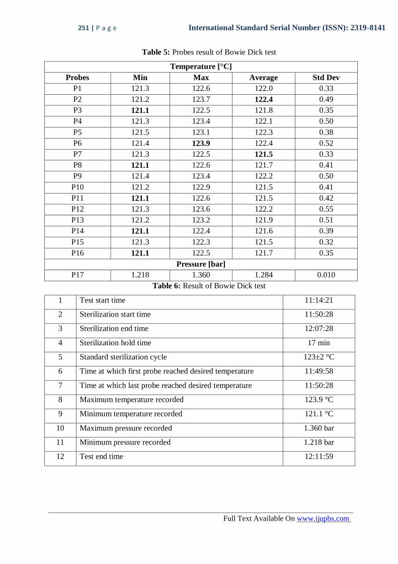
Table 5: Probes result of Bowie Dick test
Temperature [°C]
Probes Min Max Average Std Dev
P1 121.3 122.6 122.0 0.33
P2 121.2 123.7 122.4 0.49
P3 121.1 122.5 121.8 0.35
P4 121.3 123.4 122.1 0.50
P5 121.5 123.1 122.3 0.38
P6 121.4 123.9 122.4 0.52
P7 121.3 122.5 121.5 0.33
P8 121.1 122.6 121.7 0.41
P9 121.4 123.4 122.2 0.50
P10 121.2 122.9 121.5 0.41
P11 121.1 122.6 121.5 0.42
P12 121.3 123.6 122.2 0.55
P13 121.2 123.2 121.9 0.51
P14 121.1 122.4 121.6 0.39
P15 121.3 122.3 121.5 0.32
P16 121.1 122.5 121.7 0.35
Pressure [bar]
P17 1.218 1.360 1.284 0.010
Table 6: Result of Bowie Dick test
1 Test start time 11:14:21
2 Sterilization start time 11:50:28
3 Sterilization end time 12:07:28
4 Sterilization hold time 17 min
5 Standard sterilization cycle 123±2 °C
6 Time at which first probe reached desired temperature 11:49:58
7 Time at which last probe reached desired temperature 11:50:28
8 Maximum temperature recorded 123.9 °C
9 Minimum temperature recorded 121.1 °C
10 Maximum pressure recorded 1.360 bar
11 Minimum pressure recorded 1.218 bar
12 Test end time 12:11:59

252 | P a g e International Standard Serial Number (ISSN): 2319-8141
Full Text Available On www.ijupbs.com
Graph 1 : Bowie Dick test graph
Figure 2: Results of Bowie Dick test sheets
Heat distribution study
Status of equipment under validation:
Table 7: Status of heat distribution test
1 Equipment Autoclave cum bung processor
2 Make Machine fabric
3 Capacity 1215 liters
4 Acceptance criteria 123±2 °C
5 Cycle time 121 °C @ 30 min
6 Temperature range 121 °C to 125 °C
7 Pressure range 1.2 bar to 1.3 bar
8 Type of sensor used T type
9 Cycle name Without load

253 | P a g e International Standard Serial Number (ISSN): 2319-8141
Full Text Available On www.ijupbs.com
Result analysis
Table 8: Probes result of heat distribution test
Temperature[°C]
Channel Min Max Average Std dev
CH1 121.1 123.1 121.7 0.35
CH2 121.8 123.6 122.2 0.35
CH3 122.1 123.8 122.7 0.42
CH4 122.1 123.7 122.6 0.37
CH5 121.8 123.6 122.3 0.38
CH6 122.1 123.7 122.5 0.38
CH7 121.8 123.7 122.5 0.41
CH8 121.9 123.7 122.4 0.39
CH9 121.6 123.6 122.1 0.34
CH10 121.7 123.7 122.3 0.42
CH11 122.0 123.8 122.6 0.42
CH12 121.4 123.4 122.0 0.35
CH13 121.7 123.8 122.3 0.50
CH14 121.2 123.2 121.9 0.33
CH15 121.7 123.8 122.3 0.46
CH16 121.5 123.8 122.1 0.41
Pressure [bar]
CH17 1.201 1.292 1.219 0.018
Table 9: Result of heat distribution test
1 Test start time 14:36:06
2 Sterilization start time 14:58:28
3 Sterilization end time 15:29:28
4 Sterilization hold time 30 min
5 Standard sterilization cycle 123 °c±2 °C
6 Time at which first probe reached desired temperature 14:57:58
7 Time at which last probe reached desired temperature 14:58:28
8 Maximum temperature recorded 123.8 °C
9 Minimum temperature recorded 121.1 °C
10 Maximum pressure recorded 1.292bar
11 Minimum pressure recorded 1.201bar
12 Test end time 15:44:42

254 | P a g e International Standard Serial Number (ISSN): 2319-8141
Full Text Available On www.ijupbs.com
Result analysis of biological indicator
Table 10 : Biological indicator result of heat distribution study
Sterilization method By steam at a temperature of 121 °C and
pressure of 1.2 bar
Standard sterilization cycle 30 minutes
Biological indicators used Self contained ampoules of Geobacillus
stearothermophilus population 106
cfu/strip
Incubation temperature 55±2 °C
Table 11: Observation of biological indicator
S. No. Position of biological
indicator
Observation
24 hours 48 hours
1 P1 - -
2 P2 - -
3 P3 - -
4 P4 - -
5 P5 - -
6 P6 - -
7 P7 - -
8 P8 - -
9 P9 - -
10 P10 - -
11 P11 - -
12 P12 - -
13 P13 - -
14 P14 - -
15 P15 - -
16 P16 - -
17 Positive control + +
- = No growth + = Shows growth
Figure 3: Results of chemical indicators for heat distribution test

255 | P a g e International Standard Serial Number (ISSN): 2319-8141
Full Text Available On www.ijupbs.com
Graph 2: Heat distribution test graph
Heat penetration study
Status of equipment under validation
Table 12: Status of heat penetration study (maximum load)
1 Equipment Auto clave cum bung processor
2 Make Machine fabric
3 Capacity 1215 liters
4 Acceptance criteria 123 ± 2°C
5 Cycle time 121°C @ 30 min
6 Temperature range 121°C to 125°C
7 Pressure range 1.2 bar to 1.3 bar
8 Type of sensor used T type
9 Cycle name Rubber stopper maximum load (60000)

256 | P a g e International Standard Serial Number (ISSN): 2319-8141
Full Text Available On www.ijupbs.com
4.2 Result analysis
Table 13: Probes result of heat penetration study (maximum load)
Temperature[°C]
Channel Min Max Average Std dev
CH1 121.2 121.8 121.4 0.17
CH2 121.3 122.1 121.6 0.19
CH3 121.7 122.8 122.1 0.22
CH4 121.3 122.0 121.6 0.17
CH5 122.1 122.9 122.4 0.20
CH6 121.4 122.0 121.6 0.17
CH7 121.5 122.2 121.8 0.17
CH8 121.5 122.1 121.8 0.15
CH9 122.0 122.7 122.3 0.15
CH10 121.5 122.1 121.7 0.17
CH11 121.4 122.1 121.7 0.17
CH12 121.4 122.1 121.7 0.17
CH13 121.5 122.1 121.8 0.16
CH14 121.5 122.1 121.7 0.17
CH15 121.4 122.0 121.6 0.16
CH16 121.1 122.3 121.6 0.34
Pressure [bar]
CH17 1.202 1.247 1.219 0.011
Table 14: Result of heat penetration study (maximum load)
1 Test start time 11:57:14
2 Sterilization start time 16:47:50
3 Sterilization end time 17:17:50
4 Sterilization hold time 30 min
5 Standard sterilization cycle 123 °C ± 2 °C
6 Time at which first probe reached desired temperature 16:47:20
7 Time at which last probe reached desired temperature 16:47:50
8 Maximum temperature recorded 122.9 °C
9 Minimum temperature recorded 121.1 °C
10 Maximum pressure recorded 1.247 bar
11 Minimum pressure recorded 1.202 bar
12 Test end time 18:59:05

257 | P a g e International Standard Serial Number (ISSN): 2319-8141
Full Text Available On www.ijupbs.com
Figure 4: Rubber bungs for heat penetration test (maximum load)
Result analysis of biological indicator
Table 15: Biological indicator result of heat penetration study (maximum)
Sterilization method By steam at a temperature of 121 °C and pressure
of 1.2 bar
Standard sterilization cycle 30 minutes
Biological indicators used Self contained ampoules of Geobacillus
stearothermophilus population 106
cfu/strip
Incubation temperature 55±2 °C
Table 16: Observation of biological indicator
S. No. Position of biological
indicator
Observation
24 hours 48 hours
1 P1 - -
2 P2 - -
3 P3 - -
4 P4 - -
5 P5 - -
6 P6 - -
7 P7 - -
8 P8 - -
9 P9 - -
10 P10 - -
11 P11 - -
12 P12 - -
13 P13 - -
14 P14 - -
15 P15 - -
16 P16 - -
17 Positive control + +
- = No growth + = Shows growth
258 | P a g e International Standard Serial Number (ISSN): 2319-8141
Full Text Available On www.ijupbs.com
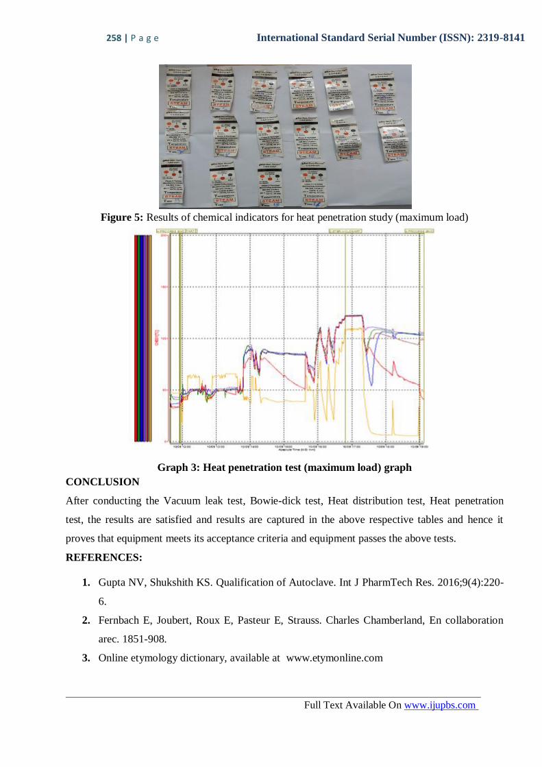
Figure 5: Results of chemical indicators for heat penetration study (maximum load)
Graph 3: Heat penetration test (maximum load) graph
CONCLUSION
After conducting the Vacuum leak test, Bowie-dick test, Heat distribution test, Heat penetration
test, the results are satisfied and results are captured in the above respective tables and hence it
proves that equipment meets its acceptance criteria and equipment passes the above tests.
REFERENCES:
1. Gupta NV, Shukshith KS. Qualification of Autoclave. Int J PharmTech Res. 2016;9(4):220-
6.
2. Fernbach E, Joubert, Roux E, Pasteur E, Strauss. Charles Chamberland, En collaboration
arec. 1851-908.
3. Online etymology dictionary, available at www.etymonline.com

259 | P a g e International Standard Serial Number (ISSN): 2319-8141
Full Text Available On www.ijupbs.com
4. Hugo WB. A brief history of heat and chemical preservation and disinfection. J Appl
Bacteriol. 1991;71(1):9-18.
5. Seymour SB. Disinfection, Sterilization and preservation, Lippincott Williams and Wilkins,
5th ed. 2001.
6. Wark G. Types of autoclaves [Internet]. How. [cited 2016 Jan 25]. Available from:
http://www.ehow.com/about 5031514 types autoclaves.html
7. Howard J. Operation of the autoclaves, available at www.oomyceteworld.net
8. Ankur C. Microbiology sterilization, available at www.pharmaguideline.com
9. Chrise W. How does an autoclave work, available at www.explainthatstuff.com
10. Allard S, Burgess G, Cuthbertson B, Elliott C, Haggas R, Jones J et.al., Guidelines for
validation & qualification including Change Control, for hospital transfusion laboratories.
2014:1-24.