239 Motor ProteCtIon systeM - GE Digital Energy
8
364 g Multilin Motor Protection • Enhanced Motor Overload Protection with Thermal Modeling • Simple configuration and system monitoring using EnerVista TM 239 Setup software • Reduced cost and commissioning time with Protection, Monitoring, and Control in a single device • Scalable protection with optional RTD inputs and advanced Motor Protection elements • Simplified testing and commissioning with built in simulation features • Field upgradable firmware and relay options • Easy access to system and relay information using Modbus RTU • Multiple groups of protection settings allows flexible protection for flexible systems • Small to Medium sized three phase AC induction and synchronous motors • Pumps, conveyors, compressors, fans, etc. • Status/current/temperature display • Fault diagnosis • Trending • Trip record, last 5 • Process control • Optional analog output Monitoring and Metering User Interface Protection and Control • Thermal Overload (15 selectable curves) - Trip and alarm, immediate current overload alarm • Phase short circuit • Mechanical jam • Thermal memory lockout • Single-Phasing /Current unbalance • Ground fault - trip and alarm • Overtemperature: via thermistor or optional RTD inputs • Undercurrent • Breaker Failure • Trip/alarm/auxiliary/service outputs • Multi-speed motor protection • Motor start supervision • 40 Character backlit display for easy viewing of settings and actual values • 6 Motor and relay status LED’s • Multiple programming keys to allow easy access to system values and relay settings FEATURES APPLICATIONS KEY BENEFITS 239 MOTOR PROTECTION SYSTEM Motor protection and management for small to medium size motors Communications • RS485 Serial Communications • Modbus RTU protocol EnerVista TM Software • State of the art software for configuration and commissioning GE Multilin products • Document and software archiving toolset to ensure reference material and device utilities are up-to-date • EnerVista TM Integrator providing easy integration of data in the 239 into new or existing monitoring and control systems
Transcript of 239 Motor ProteCtIon systeM - GE Digital Energy

364g Multilin
Mot
or P
rote
ctio
n
• EnhancedMotorOverloadProtectionwithThermalModeling
• SimpleconfigurationandsystemmonitoringusingEnerVistaTM239Setupsoftware
• ReducedcostandcommissioningtimewithProtection,Monitoring,andControlinasingledevice
• ScalableprotectionwithoptionalRTDinputsandadvancedMotorProtectionelements
• Simplifiedtestingandcommissioningwithbuiltinsimulationfeatures
• Fieldupgradablefirmwareandrelayoptions• Easyaccesstosystemandrelayinformationusing
ModbusRTU
• Multiplegroupsofprotectionsettingsallowsflexibleprotectionforflexiblesystems
• SmalltoMediumsizedthreephaseACinductionandsynchronousmotors
• Pumps,conveyors,compressors,fans,etc.
• Status/current/temperaturedisplay• Faultdiagnosis• Trending• Triprecord,last5• Processcontrol• Optionalanalogoutput
Monitoring and Metering
User Interface
Protection and Control• ThermalOverload(15selectablecurves)-Tripandalarm,
immediatecurrentoverloadalarm• Phaseshortcircuit• Mechanicaljam• Thermalmemorylockout• Single-Phasing/Currentunbalance• Groundfault-tripandalarm• Overtemperature:viathermistororoptionalRTDinputs• Undercurrent• BreakerFailure• Trip/alarm/auxiliary/serviceoutputs• Multi-speedmotorprotection• Motorstartsupervision
• 40Characterbacklitdisplayforeasyviewingofsettingsandactualvalues
• 6MotorandrelaystatusLED’s• Multipleprogrammingkeystoalloweasyaccessto
systemvaluesandrelaysettings
FeatUres
aPPlICatIons
Key BeneFIts
239Motor ProteCtIon
systeMMotorprotectionandmanagement
forsmalltomediumsizemotors
Communications• RS485SerialCommunications• ModbusRTUprotocol
enerVistatM software• Stateoftheartsoftwareforconfigurationand
commissioningGEMultilinproducts• Documentandsoftwarearchivingtoolsettoensure
referencematerialanddeviceutilitiesareup-to-date• EnerVistaTMIntegratorprovidingeasyintegrationofdata
inthe239intoneworexistingmonitoringandcontrolsystems
www.GeMultilin.com
239 Motor Protection system
365
Mot
or P
rote
ctio
n
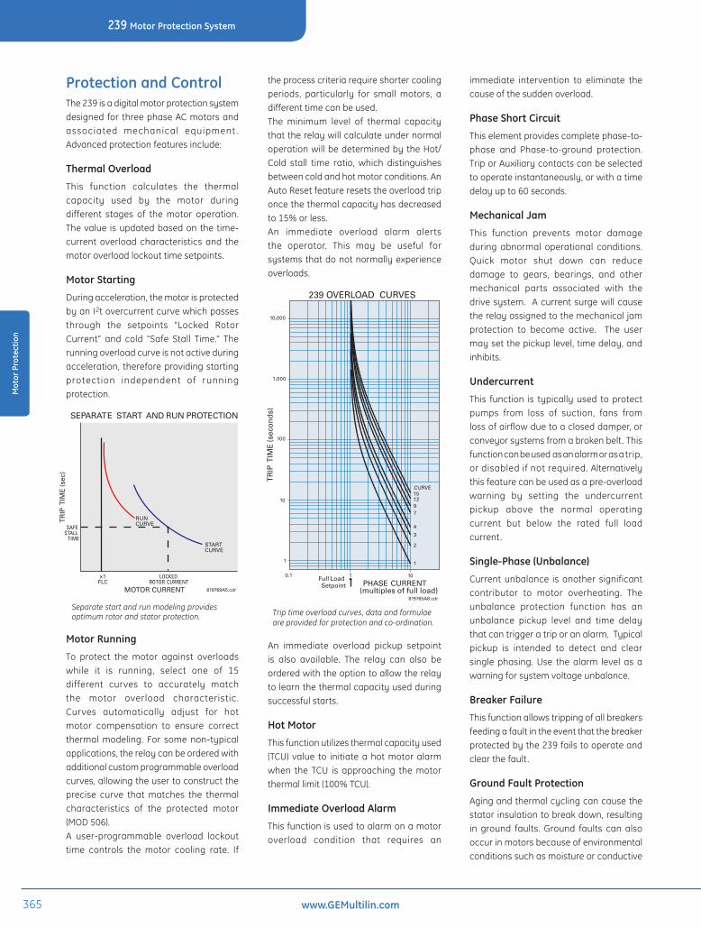
Protection and ControlThe239isadigitalmotorprotectionsystemdesignedfor threephaseACmotorsandassociated mechanical equipment .Advancedprotectionfeaturesinclude:
thermal overload
This function calculates the thermalcapacity used by the motor duringdifferent stages of themotor operation.Thevalue isupdatedbasedonthetime-currentoverloadcharacteristicsand themotoroverloadlockouttimesetpoints.
Motor starting
Duringacceleration,themotorisprotectedbyanI2tovercurrentcurvewhichpassesthrough the setpoints “Locked RotorCurrent” and cold “Safe Stall Time.” Therunningoverloadcurveisnotactiveduringacceleration,thereforeprovidingstartingprotection independent of runningprotection.
Motor running
To protect the motor against overloadswhile it is running, select one of 15different curves to accurately matchthe motor overload characteristic.Curves automatically adjust for hotmotor compensation to ensure correctthermalmodeling. For somenon-typicalapplications,therelaycanbeorderedwithadditionalcustomprogrammableoverloadcurves,allowingtheusertoconstructtheprecise curve thatmatches the thermalcharacteristics of the protected motor(MOD506).A user-programmable overload lockouttime controls the motor cooling rate. If
theprocesscriteriarequireshortercoolingperiods, particularly for small motors, adifferenttimecanbeused.The minimum level of thermal capacitythattherelaywillcalculateundernormaloperationwillbedeterminedbytheHot/Cold stall time ratio, which distinguishesbetweencoldandhotmotorconditions.AnAutoResetfeatureresetstheoverloadtriponcethethermalcapacityhasdecreasedto15%orless.An immediate overload alarm alertsthe operator. This may be useful forsystemsthatdonotnormallyexperienceoverloads.
An immediate overload pickup setpointis also available. The relay can also beorderedwiththeoptiontoallowtherelaytolearnthethermalcapacityusedduringsuccessfulstarts.
Hot Motor
Thisfunctionutilizesthermalcapacityused(TCU) value to initiateahotmotoralarmwhen the TCU is approaching themotorthermallimit(100%TCU).
Immediate overload alarm
Thisfunctionisusedtoalarmonamotoroverload condition that requires an
immediate intervention to eliminate thecauseofthesuddenoverload.
Phase short Circuit
Thiselementprovidescompletephase-to-phase and Phase-to-ground protection.TriporAuxiliarycontactscanbeselectedtooperateinstantaneously,orwithatimedelayupto60seconds.
Mechanical Jam
This function prevents motor damageduring abnormal operational conditions.Quick motor shut down can reducedamage to gears, bearings, and othermechanical parts associated with thedrivesystem. Acurrentsurgewillcausetherelayassignedtothemechanicaljamprotection to become active. The usermaysetthepickuplevel,timedelay,andinhibits.
Undercurrent
This function is typicallyused toprotectpumps from loss of suction, fans fromlossofairflowduetoacloseddamper,orconveyorsystemsfromabrokenbelt .Thisfunctioncanbeusedasanalarmorasatrip,ordisabledifnotrequired.Alternativelythisfeaturecanbeusedasapre-overloadwarning by setting the undercurrentpickup above the normal operatingcurrent but below the rated full loadcurrent.
single-Phase (Unbalance)
Currentunbalance is another significantcontributor to motor overheating. Theunbalance protection function has anunbalance pickup level and time delaythatcantriggeratriporanalarm.Typicalpickup is intended to detect and clearsinglephasing.Use thealarm level asawarningforsystemvoltageunbalance.
Breaker Failure
Thisfunctionallowstrippingofallbreakersfeedingafaultintheeventthatthebreakerprotectedbythe239failstooperateandclearthefault .
Ground Fault Protection
Agingandthermalcyclingcancausethestatorinsulationtobreakdown,resultingin ground faults. Ground faults can alsooccurinmotorsbecauseofenvironmentalconditionssuchasmoistureorconductive
15CURVE
1297
4
3
2
1
10
819765A8.cdr
PHASE CURRENT(multiples of full load)
1Full LoadSetpoint
239 OVERLOAD CURVES
0.1
10,000
1,000
100
TR
IPT
IME
(sec
on
ds)
10
1
Trip time overload curves, data and formulae are provided for protection and co-ordination.
MOTOR CURRENT
SEPARATE START AND RUN PROTECTION
TR
IPT
IME
(sec
)
SAFESTALL
TIME
RUNCURVE
STARTCURVE
LOCKEDROTOR CURRENT
x1FLC
819769A5.cdr
Separate start and run modeling provides optimum rotor and stator protection.

www.GeMultilin.com 366
239 Motor Protection system
Mot
or P
rote
ctio
n
dust.The239cantriggeratriporanalarmif the ground pickup level is exceeded.A time delay may be entered for timecoordinationofsystemswithseverallevelsofgroundfaultdetection. Therearetwogroundinputsavailableinthe239,allowingtwomethodsofgroundprotection.
• Corebalance(Zerosequence)HighImpedanceGroundFault(HGF)currenttransformerswith5Asecondary
• Corebalance(Zerosequence)currenttransformerswitha50:0.025Ampcurrentratioforsensitivecurrentdetection.
WhentheresidualconnectionofthephaseCTs is used to detect ground currents,nuisancetripscanoccurduringstartdueto unequal saturation of CTs. This maycauseZerosequencecurrentstoappear,ofsufficientmagnitudetoreachthepickupsetting of the Ground Fault protectionfunction. Toavoid this, the239has twoindependent timedelaysettings,one formotorstarting,andoneformotorrunning.The239canbeorderedwithMOD512for1AgroundcurrentinputandMOD509fordirectiongroundfaultsensing.
overheating
Direct temperature sensing isnecessarytodetecttheeffectsofmotoroverheatingdue to blocked ventilation or highambient temperature. Temperaturerise under these types of conditions isusuallyslowenoughtoallowtheaccuratesensingoftheactualmotortemperature.Amotortemperatureinputforathermistorisstandardonthe239.Additionally,threeRTDslocatedinthestatorand/orbearingscanbeconnectedtothe239withtheRTDtemperaturesensingoption.Thisprovidesdisplayedtemperaturesaswellasalarmand trip settings for both bearing andstatorRTDs.FourRTDtypesaresupported:100Pt , 120Ni, 100Ni, and 10Cu. A RTDfailurealarmisalsoprovided.
Monitoring and MeteringThe 239 provides users with advancedmonitoring andmetering functions thatinclude:
Metering
Measuredvaluesinclude:
• Phasecurrent
• Groundcurrent
• Currentunbalance
• Current%offullload
• Motorloadcurrentasa%offullload
• Motorthermalcapacityused
• Statortemperature(RTDoption)
• Bearingtemperature(RTDoption)
Multi-speed Motors
Optional switches allow alternateparameterstobeactivatedforprotectionofmulti-speedmotors.Additionalsettingsprovided with multiple speed motorprotectioninclude:
• PhaseCTprimary
• Fullloadcurrent
• Overloadcurve
• Shortcircuittripsettings
Motor start supervision (MoD 505)
The239relaycanbe furnishedwith thisfunction,whichisanenhancedprotectionagainst multiple starts. The functionconsistof2elements:
• TimeBetweenStarts
• StartsperHour
819763AF.cdr
51
49
38
50
37
86/94
74
46
50G
39
MOTORLOAD
AUXILIARYRELAY
SERVICERELAY
RS485
ALARMRELAY
TRIPRELAYMECHANICAL JAM
SHORT CIRCUIT
TIMED OVERLOAD
INSTANTANEOUSGROUND FAULT
STATOR OVERTEMPERATUREBEARING OVERTEMPERATURE
UNBALANCE
UNDERCURRENT
SERVICEALARM
FAULT/ALARM/PROCESSCONTROL
FAULT/PROCESSALARM
523 PHASE4160V BUS
400A
FUSEDCONTACTOR
3PHASE CTs
TRIP
GROUNDCT
THERMISTOR/STATOR RTD
BEARINGRTDs
RS485 REMOTECOMMUNICATION
239 Motor Protection System
Functional Block Diagram
DeviceNumber Function
37 Undercurrent/minimumload
38 Motor/loadbearingOvertemperature
39 Mechanicaljam46 Currentunbalance49 Statorwindingovertemperature50 Phaseshortcircuit51 Timedoverload
50G/50N Groundfaultinstantaneousordefinitetime
74 Alarmrelay86/94 Lockoutandtriprelay
ANSIDeviceNumbers&Functions

www.GeMultilin.com
239 Motor Protection system
367
Mot
or P
rote
ctio
n
Fault Diagnosis
The239keepsarecordofthecauseofthelast five trips issued. The relaywill alsorecordthephasecurrent,groundcurrent,and RTD temperaturesmeasured at thetimeofthelasttrip.
Motor alarmingAlarm functions include immediateoverloadwarning,unbalance,undercurrentand internal self check fault . Often analarmcanbegeneratedsoonenoughtoenablecorrectiveactiontobetakenbeforeatripoccurs.
testing
While periodic calibration is notrequired,thePICKUPLEDisusefulduringcommissioning or routine verificationto indicate the pickup point for phaseoverload or ground. A simulation modeis also available that enables simulatedcurrentstobeusedwithouttheneedforarelaytestset.Thisisidealforverificationofsettingsand training. Itallows forcingofoutputrelays,LEDs,switchinputs,RTD,Thermistor input resistance, and Analogoutputs.
automation
analog output option
The analog output option provides anisolated0to1,0to20,or4to20mAsignalforinterfacetoaPLC.Thisoutputcanbeprogrammedas:averagephasecurrent ,motorfullload%,thermalcapacityused,or RTD temperature. For local operatormonitoring, a thermal capacity metercanbeusedwiththisoutput.Informationsuchasprocessloadingandproximitytotrippingor overheating canbeobtainedwiththisoutput.
output relays
The239hasthreeoutputrelays.Theyarethe Trip, Alarm, and Aux contacts. Thetriprelayactsasthemainlatchedoutputrelay.The Alarm and Auxiliary relays may beprogrammed for latched or unlatchedmodes. All relays may be programmedfail-safeornonfail-safe. Ifconfiguredaslatched relays, they canbe reset via anexternalresetswitchconnectedtooneofthe239digitalinputs,fromthekeypadorviaserialcommunication.
switch Inputs
The 239 has three fixed and two userdefinableswitchinputs:
• Setpointaccess:theseterminalsmustbeshortedtogetherforkeypadsetpointconfiguration
• Emergencyrestart:momentarilyshortingtheseterminalstogetherwhenthemotorisstoppedwillresetthethermalcapacityusedto0%,allowingforanimmediaterestartafteranoverloadtrip.Asthiswillcompromisethethermalprotectionfunctionsofthe239,makingitpossibletodamagethemotor,thisfunctionshouldonlybeusedinemergencysituations
• Externalreset:thisinputallowsremoteorautomaticresetingoflatchedtripsoralarms
CommunicationsThe 239 features an RS485 connectionwithModBus®RTUprotocoltocommunicatewithmosttypesofPLCsandcomputers.This allows anymonitored value, status
Use Viewpoint monitoring to receive instant feedback of the motor and relay status
Troubleshoot motor faults using the 239 Cause Of Last Trip record

www.GeMultilin.com 368
239 Motor Protection system
Mot
or P
rote
ctio
n
and setpoints to be remotely accessedbyaPLCorSCADAsystem.AfrontpanelLED verifies correct operation of thecommunicationport.The 239 is also capable of beingintegrated into a local area networkusing the MultinetTM Serial to Ethernetconverter.Networkingallowseasyaccessto information frommultiplemonitoringandcontroldevicessuchasSCADA’sandHMI’s.
User InterfaceThe40characterLCDandkeypadprovideconvenient local communications andcontrol.Setpointscanbemodifiedlocallyusing the keypad and display. To helpprevent unauthorized setpoint changes,asetpointaccess inputmustbeshortedbeforechangescanbemade.
leD Indicators
Six LED indicators on the front panelprovidequickvisualindicationofstatus.
enerVistatM softwareTheEnerVista™Suiteisanindustryleadingsetofsoftwareprogramsthatwillsimplifyeveryaspectofusingthe239relay.Toolstomonitorthestatusofyourmotor,maintainyour relay, and integrate informationmeasuredbythe239 intoHMIorSCADAmonitoringsystemsareavailable.
enerVista™ launchpad
EnerVista™ Launchpad is a powerfulsoftwarepackagethatprovidesuserswithallofthesetupandsupporttoolsneeded for configuring andmaintainingGE Multilin products. Launchpad allowsconfiguringdevicesinreal-timebycommunicatingusingserial,Ethernet ,ormodemconnections,orofflinebycreatingsettingfilestobesenttodevicesatalater
time.IncludedinLaunchpadisadocumentarchivingandmanagement system thatensurescriticaldocumentationisup-to-dateandavailablewhenneeded.Documentsmadeavailableinclude:
•Manuals
•ApplicationNotes
•GuideformSpecifications
•Brochures
•WiringDiagrams
•FAQ’s
•ServiceBulletins
Viewpoint Monitoring
Viewpoint Monitoring is a powerful yetsimple-to-use monitoring and datarecording of small systems. ViewpointMonitoring provides a complete HMIpackagewiththefollowingfunctionality:
•Plug-&-PlayDeviceMonitoring
•Single-LineMonitoring&Control
•AnnunciatorAlarming
•TrendingReports
enerVista™ Integrator
EnerVistaTM Integrator is a toolkit that
allowsseamlessintegrationofGEMultilindevices intoneworexistingautomationsystems.IncludedinEnerVistaTMIntegratoris:
•OPC/DDEServer
•GEMultilinDrivers
View motor current, temperature, statistics and status.
Enter setpoints directly to the 239 or copy/save relay settings to a file.
Use Viewpoint monitoring to receive instant feedback of the motor and relay status
KEYPADRubber keypad makes installed unit dust tight and splash proof. Meets IP53/NEMA12.
PROTECTIVE DOORCovers keys when not in use.
COMPACT DESIGNReplaces many discrete compo nents with one
819790AG.cdr
CUSTOMER ACCESSIBLE FUSEDoor slides open for easy access to fuse.
PHASE CT INPUTS3 isolated phase CT inputs. Accept 1 amp or 5 amp secondary.
GROUND CT INPUT5 A or 50:0.025 CT input for residually connected phase CTs or separate core balance CT.
AC/DC CONTROL POWERUniversal control power 90-300 VDC/70-265 VAC.
TEMPERATURE SENSINGNTC or PTC thermistor input.
OPTIONAL ANALOG OUTPUTSelect output as: thermal capacity used, current as a % of full load, average current, RTD 1 Ð 3 temperature. Isolated 4 Ð 20 mA for PLC process input or 0 Ð 1 mA for thermal capacity meter.
COMMUNICATIONSRS485 serial communications, 1200 Ð 19200 baud for remote monitoring, setpoint programming, and commands. Modbus¨ RTU protocol.
OPTIONAL 3 RTD INPUTSMix RTD types. Separate stator and bearing monitoring.
OPTIONAL DIRECTIONAL GROUND SENSINGPolarizing voltage input for directional ground sensing(MOD 509)
standard unit.
User Interface

www.GeMultilin.com
239 Motor Protection system
369
Mot
or P
rote
ctio
n
typical Wiring
2 CT CONNECTION(NO GROUND)
RESIDUAL GROUND CONNECTION
ZERO SEQUENCE GROUND CONNECTION
PHASE A CT PHASE A CT
PHASE A CTSTARTER
80-300 VDC70-265 VAC 50/60 Hz
CONTROL POWER
SUPPLY 50:0.025GROUND CT
CONTACTORCOIL
SWITCHGEARGROUND BUS
PHASE C CT PHASE C CT
PHASE C CT
PHASE B CT
PHASE B CT
L1 L1
L1L1A
B
C
TWISTLEADS
L2 L2
L2L2MOTOR
L3 L3
L3L3
1 1
1
2 2
2
3 3
3
4 4
4
5 5
5
6 6
6
7 7
7
8 8
8
9 9
9
10 10
10
11 11
11
12 12
12
5A 5A
5A
5A 5A
5A
5A 5A
5A
5A 5A
5A
1A 1A
1A
1A 1A
1A
1A 1A
1A
COM COM
COM
COM COM
COM
COM COM
COM
COM COM
COM
PHASE A PHASE A
PHASE A
PHASE B PHASE B
PHASE B
PHASE C PHASE C
PHASE C
GROUND GROUND
GROUND
50:0.025 50:0.025
50:0.025
CONTROLPOWERN L
START STOP
GENERAL ALARM
CONTROLPOWER
232425
NO
NO
NO
NO
IN
IN
IN
IN
IN
COM
COM
COM
COM
COM
COM
COM
COM
COM
NC
NC
NC
NC
262728293031323334
43384439454046414742
SETPOINTACCESS
ACCESSKEY SWITCH
EMERGENCYRESTART
EMERGENCYRESTART
EXTERNALRESET
EXTERNALRESET
OPTION 1OPTION 1
OPTION 2OPTION 2
S1
S2
S3
S4
S5
SW
ITC
H IN
PU
TS
OU
TP
UT
RE
LAY
S
RELAY #1TRIP
RELAY #2ALARM
RELAY #3AUXILIARY
RELAY #4SERVICE
CURRENT INPUTS
13 14 36 37SAFETY
GROUNDFILTER
GROUNDL
+N
-
RS485 +
RS485 -
485 GROUNDSE
RIA
L
RT
D#1
RT
D#2
RT
D#3
RT
D T
EM
PE
RA
TU
RE
SE
NS
ING
AN
ALO
GO
UT
0-1m
A
4-20
mA
151617
181920SHIELD
USE SHIELDED TWISTEDPAIR WIRE
RS485
THERMALCAPACITY
THERMISTORIN+
COM
2122
4849505152
SHIELD
HOT
COMP
RET
HOT
5354555657
COMP
RET
HOT
COMP
RET
STATORTHERMISTOR
STATORRTD
STATOR/BEARING RTD
STATOR/BEARING RTD
USE SHIELDED WIRE
819829B7.cdr819751B5.DWG
NOTES:
1) 3)
4)2)
RELAY CONTACT STATE SHOWN WITHCONTROL POWER NOT APPLIED.
SHIELD TERMINALS ARE INTERNALLYCONNECTED TO SAFETY GROUNDTERMINAL 13
RTD TEMPERATURE SENSINGAND ANALOG OUTPUT OPTIONAL
RELAY FACTORY DEFAULTS:TRIP, ALARM, AUXILIARY: SERVICE:
NON-FAILSAFEFAILSAFE
CC
Multilin 239Motor Protection Systemg

www.GeMultilin.com 370
239 Motor Protection system
Mot
or P
rote
ctio
n
technical specificationsCoMMUnICatIonstype: RS4852wire,halfduplex,isolatedBaud rate: 1200–19,200bpsProtocol: ModBus®RTUFunctions: Read/writesetpoints,readactual
values,executecommands
aPProValsManufacturedunderanISO9001registeredsystemUl: RecognizedunderE83849Csa: ApprovedunderLR41286
ProDUCtIon testsDielectric strength: 1.836kVACfor1sectorelays,
CTs,powersupply
enVIronMentaltemperature range operating: 0°Cto60°C storage: -40°Cto70°CambientHumidity: 95%non-condensingPollution degree: 2overvoltage category: 2IP class: 40Insulation voltage: 300Vnote:LCDcontrastimpairedbelow-20°C
*Specificationssubjecttochangewithoutnotice.
PaCKaGInGshipping box: 8.5”Lx6”Hx6”D
(215mmx152mmx152mm)ship weight: 5lbs(2.3kg)
FUse tyPe/ratInG5x20mm,2.5A,250VSlowblow,highbreakingcapacity
ProteCtIontHerMal MoDel / oVerloaDoverload Curves: separate start and run overload Curves run: 15Curves,fixedshape start: PerEquation:T(I)=TsstxI2
I2LRCWhere: Tsst=SaveStallTime
ILRC=LockedRotorCurrentsave stall time range: 1.0-600.0seclocked rotor Current range:
0.5-11.0xFLCoverload Pickup range (FlC):
0.1-150 A for CT Pri Set < 50A1-1500AforCTPriSet>50A
accuracy:Pickup: ±1%ofdisplayedvaluetime: ±2%oftriptimeor±1sec
whicheverisgreateroverload Pickup Inhibit range:
1.0-5.0xFLCHot Motor alarm Pickup range:
1-100%Hot Motor alarm time: InstantaneousCooling Features: Separatestopandruncooling
rates.Exponentialcooldownlockout time (cool down rate):stop: 1-5000minprogrammable
±20%powerONorOFFrun: 50%ofstoppedcoolingtimeHot/Cold stall time ratio range:
5-100%oVerloaD CUrVes trIP tIMe Curves: 15curves,fixedshapeoverload pickup inhibit: 1.0–5.0xFLCPickup level: 1–1500Aaccuracy:Pickup: ±1%ofdisplayedvaluetime: ±2%oftriptimeor±1sec
whicheverisgreatersHort CIrCUIt anD GroUnD trIPGround trip level: 0.05–15A(50:0.025CT)
3–100%(5ACT)s/C trip level: 1–11xCTPRI/OFFIntentional delay: INST.or10msto60000ms
programmableInstantaneous: 20–45ms*total delay: Instantaneous+intentional*trip time accuracy guaranteed if current >1.4 x trip level setting BreaKer FaIlUre tIMInGDelay: INST.or10msto60000ms
programmableInstantaneous: 20–45ms*total delay: Instantaneous+intentional*trip time accuracy guaranteed if current >1.4 x trip level settingstart ProteCtIonthermal: Separatestartandrun
protectionactivation: Inrush3phasecurrentincrease
from<5%to>101%FLCin1sec
Deactivation: Currentdropsto<100%FLCrunningifcurrent>5%FLC
locked rotor: 0.5–11.0xFLCsafe stall time: 1.0–600.0secUnBalanCerange: 5–100%/OFFaccuracy: ±2%Delay: 0–60sec
UnDerCUrrentRange: 5–100%FLC/OFFDelay: 0–250sec
Calculation: Im-Iav ifIav>IFLCUB%=|______|x100 Iav Im-Iav ifIav<IFLCUB%=|______|x100 IFLC
where: Iav=averagephasecurrent Im=currentinphasewithmaximum deviationfromIav IFLC=fullloadcurrentsetting
ProteCtIontHerMal MoDel / oVerloaDrtDs (oPtIon)Inputs: 3RTDs,stator/bearing
programmableType: 100Pt(DIN43760),100Ni,120
Ni10CuprogrammableRange: -40to200°C/-40to400°FTrip/alarmrange: 0to200°C/0to400°FDeadband: 2°C/4°FAccuracy: ±2°C/4°FLeadResistance: PtorNiRTD:25 max
CuRTD:3 max3-wireleadresistancecompensation
tHerMIstorType: PTCorNTCprogrammableHotresistance: 100–30,000 Coldresistance: 100–30,000 Delay: 2secAccuracy: ±5%or100 (whicheveris
greater)
MeterInGPHase CUrrent InPUtsConversion: TrueRMS,16samples/cycleCt Input: 1Aand5Asecondaryrange: 0.1to11xphaseCTprimaryFrequency: 20–300Hzaccuracy: ±2%offullscaleGroUnD CUrrent InPUtsConversion: TrueRMS,16samples/cycleCt input: 5Asecondaryand50:0.025range: 0.03to1.4xCTprimary(5ACT)
0.05to16.0A(50:0.025CT)Frequency: 20–300Hzaccuracy 5a Ct: ±2%offullscale(5ACT) 50:0.025 Ct: ±0.03A(0–0.49A)
±0.07A(0.50–3.99A)±0.20A(4.00–16.00A)
InPUtssWItCH InPUtstype: Drycontactsoutput: 29VDC,10mA(pulsed)Duration: 100msminimum
Ct InPUt(a)
BUrDen(Va) (Ž)
Phase Ct (1 a)1 0.009 0.015 0.2 0.0120 3.5 0.01
Phase Ct (5 a)5 0.04 0.00225 0.9 0.002100 16 0.002
Ground Ct (5 a)5 0.04 0.00225 1.1 0.002100 17 0.002
Ground Ct (50:0.025)
0.025 0.07 1160.1 1.19 1190.5 30.5 122
WItHstanD1 seC x Ct 5 seC x Ct ContInUoUs
x CtPhase Ct (1 a) 100 40 3Phase Ct (5 a) 100 40 3
Ground Ct (5 a) 100 40 3
50:0.025GROUNDINPUTWITHSTANDContinuous 150mAMaximum 12Afor3cycles
50:0.025inputcanbedrivenbya50:0.025CT
PoWer sUPPlyInput: 90–300VDCor70–265VAC,
50/60HzPower: 10VA(nominal),20VA(max)Holdup non-failsafe trip: 200ms Failsafe trip: 100msbothtimes
at120VAC/125VDCNote:Itisrecommendedthatall239relaysbepoweredupatleastonceperyeartoavoiddeteriorationofelectrolyticcapacitorsinthepowersupply.
oUtPUtsanaloG oUtPUt (oPtIon)
ProgrammableoUtPUt 0–1mA 0–20mA 4–20mA
Max loaD 2400 600 600Max oUtPUt 1.1mA 21mA 21mA
accuracy: ±2%offullscalereadingIsolation: 36VDCisolated,activesource
oUtPUt relays
VOLTAGE M/CCONT.
M/C0.2SEC
BREAK
DCResistive 30VDC 10A 30A 10A125VDC 10A 30A 0.5A250VDC 10A 30A 0.3A
DCInductive 30VDC 10A 30A 5A125VDC 10A 30A 0.25A
(L/R=7ms) 250VDC 10A 30A 0.15AACResistive 120VAC 10A 30A 10A
250VAC 10A 30A 10AACInductive 120VAC 10A 30A 10APF=0.4 250VAC 10A 30A 10AConfiguration: FormCNO/NC
ContactMaterial: SilverAlloy
tyPe testsInsulation resistance: IEC255-5500VDCtransients: ANSIC37.90.1oscillatory
2.5kV/1MHzANSIC37.90.1fastrise5kV/10nsOntarioHydroA-28M-82IEC255-4impulse/highfrequencydisturbanceclassIIIlevel
Impulse test: IEC255-50.5J5kVrFI: 50MHz/15WtransmittereMI: C37.90.2electromagnetic
interference@150MHzand450MHz,10V/m
static: IEC801-2staticdischargeenvironment: IEC68-2-38temperature/humidity
cycleDust/moisture: NEMA12/IP53Dielectric strength: 2.0kVACfor1mintorelays,CTs,
powersupplytemperature: -10°Cto60°Cambient
InstallatIonWarning: Hazardmayresultiftheproductis
notusedforitsintendedpurpose.Ventilation requirements: NoneCleaning requirements: None

www.GeMultilin.com
239 Motor Protection system
371
Mot
or P
rote
ctio
n
239 * * * 239 Basicunit rtD 3RTDs:stator/bearing;programmabletype:platinum,nickel,copper an Singleisolated,analogoutput:0–1,0–20,4–20mA
Programmableoutputparameters:thermalcapacity,%fullload, phasecurrent,RTD1,RTD2,RTD3temperature
H Harshenviornmentconformalcoating
ordering
082611-v6
• ViewpointMonitoring VP-1
• 50:0.025GroundCT HGF3
• MultinetSerialtoEthernetconverterMULTINET-FE
• 2.25”ShallowMountCollar 1009-0068
accessories for the 239 • ViewGuideformSpecifications
• Downloadtheinstructionmanual
• Reviewapplicationsnotesandsupportdocuments
• Buyan239online
Visit www.GeMultilin.com/239 to:
ModificationsMOD500: Portabletest/carryingcaseMOD501: 20to60VDC/20to48VACcontrolpowerMOD504: RemovableterminalblocksMOD505: EnhancedstartprotectionMOD506: CustomprogrammableoverloadcurveMOD509: Directionalgroundsensingwith120VACpolarizingvoltageMOD512: 1AmpgroundCTinputMOD513: Class1Division2operationMOD517: AustralianMinesapproval