2262 IEEE TRANSACTIONS ON NUCLEAR SCIENCE, VOL. 51, NO. 5
5
2262 IEEE TRANSACTIONS ON NUCLEAR SCIENCE, VOL. 51, NO. 5, OCTOBER 2004 Single Electron Amplification in a “Single-MCP Micromegas Pads” Detector J. Va’vra and T. Sumiyoshi Abstract—We have tested a new gaseous detector structure based on a tandem of two parts, the first one is a single MCP plate (some- times called the Microchannel plate or capillary plates), and the second one is a Micromegas with pad readout. The new detector responds very well to a single electron signal, both in helium-based and argon-based gases, and it can reach a very large gain. Our overall aim is to couple the proposed electrode structure to a Bial- kali photocathode. The main advantage of this avenue of research is that such a detector would operate easily in a very large mag- netic field, and it could achieve excellent position resolution and large pixelization, compared to existing vacuum-based MCP-PMT detectors. Index Terms—Gaseous micromegas and MCP-based detectors, micro-pattern detectors, photon detectors. I. INTRODUCTION W E have a strong research and development effort in our group to develop a Focusing DIRC [1]–[4]. This is a Cherenkov imaging detector, which will attempt to remove the chromatic error contribution to the Cherenkov angle error by precise timing on each single photon. As the total timing spread due to “color” of photons in a Focusing DIRC with a 4-m-long fused silica bar with a photon detector equipped with a Bialkali photocathode is only 0.5–1.5 ns at most (depending how far the photon travels on the fused silica bar), one needs a timing resolution of 100 ps or better for each Cherenkov photon to be able to “color-tag” photons. The chromatic error is typically the dominant error. So far, there is no Cherenkov detector which has ever corrected the chromatic error. If one would succeed to eliminate the chromatic error, and if one could have the small pixel size at the same time, one could push the separation in the Focusing DIRC up to 6–8 GeV/c compared to the present DIRC in BaBar, where the limit is up to 3–4 GeV/c. Presently, the strongest photon detector candidate for this task is a vacuum-based Multi-MCP-PMTs, for example, one made by the Burle Co. 1 This device has two MCPs with 25- m hole diameter. We have achieved a timing resolution of 50–60 ps with the vacuum-based MCP-PMT—see Fig. 1. This device works Manuscript received November 18, 2003; revised February 12, 2004. This work was supported by the Department of Energy under Contract DEAC03- 76SF00515 and supported in part by a Grand-in-Aid for Scientific Research from JSPS under Grant 14340083 and the Japan/U.S. cooperation program in the field of high energy physics. J. Va’vra is with the Stanford Linear Accelerator Center (SLAC), Stanford, CA 94305 USA (e-mail: [email protected]). T. Sumiyoshi is with the Tokyo Metropolitan University, Tokyo, Japan. Digital Object Identifier 10.1109/TNS.2004.836064 1 Burle Technologies Inc., http://www.burle.com Fig. 1. Single electron timing resolution obtained with a vaccuum-based Burle MCP-PMT, and PiLas red laser diode. The MCP-PMT has two microchannel plates (MCP or capillary). This measurements indicates that there is a good transit time distribution in the vacuum-based capillary. A long tail is explained by the recoil photoelectrons from the front MCP surface. very well, however, it is not yet suitable for 1.5-T operation be- cause the hole diameter is too large. Future devices will have 5- or 10- m hole diameters, and they will operate in high mag- netic field. One drawback of the vacuum-based MCP detectors is aging due to the ion bombardment of the photocathode. Ac- cording to the Burle Co., the photocathode aging of their devices has improved by a factor of compared to previous gen- erations of such devices. This was accomplished by improve- ment of vacuum to remove residual gases. It will be interesting to see MCP results with smaller hole diameters as the scrub- bing is more difficult. I should add that we have not yet per- formed the aging tests with it. Another potential problem with all MCP vacuum-based devices is rather large major photoelec- tron losses: (a) 30%–40% due to geometrical collection effi- ciency of the first MCP and (b) due to recoils of the photoelectrons from the first MCP surface, contributing to the timing tail. We have asked a question if a gaseous device could compete with a vacuum MCP-PMT. This would require solving a number of challenging tasks. The most challenging one is to solve a gas purity to such a level that the Bialkali photocathode would have a reasonable life time. A similar challenge would be to obtain a timing resolution in a gaseous device below 100 ps. One also has to reduce the positive ion backflow to the photocathode to limit the production of secondary photoelectrons, which could trigger the positive feedback. Although ions in the gaseous detector are 0018-9499/04$20.00 © 2004 IEEE
Transcript of 2262 IEEE TRANSACTIONS ON NUCLEAR SCIENCE, VOL. 51, NO. 5
2262 IEEE TRANSACTIONS ON NUCLEAR SCIENCE, VOL. 51, NO. 5, OCTOBER 2004
Single Electron Amplification in a “Single-MCP +Micromegas + Pads” Detector
J. Va’vra and T. Sumiyoshi
Abstract—We have tested a new gaseous detector structure basedon a tandem of two parts, the first one is a single MCP plate (some-times called the Microchannel plate or capillary plates), and thesecond one is a Micromegas with pad readout. The new detectorresponds very well to a single electron signal, both in helium-basedand argon-based gases, and it can reach a very large gain. Ouroverall aim is to couple the proposed electrode structure to a Bial-kali photocathode. The main advantage of this avenue of researchis that such a detector would operate easily in a very large mag-netic field, and it could achieve excellent position resolution andlarge pixelization, compared to existing vacuum-based MCP-PMTdetectors.
Index Terms—Gaseous micromegas and MCP-based detectors,micro-pattern detectors, photon detectors.
I. INTRODUCTION
WE have a strong research and development effort in ourgroup to develop a Focusing DIRC [1]–[4]. This is a
Cherenkov imaging detector, which will attempt to remove thechromatic error contribution to the Cherenkov angle error byprecise timing on each single photon. As the total timing spreaddue to “color” of photons in a Focusing DIRC with a 4-m-longfused silica bar with a photon detector equipped with a Bialkaliphotocathode is only 0.5–1.5 ns at most (depending how farthe photon travels on the fused silica bar), one needs a timingresolution of 100 ps or better for each Cherenkov photon to beable to “color-tag” photons. The chromatic error is typically thedominant error. So far, there is no Cherenkov detector whichhas ever corrected the chromatic error. If one would succeed toeliminate the chromatic error, and if one could have the smallpixel size at the same time, one could push the separationin the Focusing DIRC up to 6–8 GeV/c compared to the presentDIRC in BaBar, where the limit is up to 3–4 GeV/c.
Presently, the strongest photon detector candidate for this taskis a vacuum-based Multi-MCP-PMTs, for example, one madeby the Burle Co.1 This device has two MCPs with 25- m holediameter. We have achieved a timing resolution of 50–60 ps withthe vacuum-based MCP-PMT—see Fig. 1. This device works
Manuscript received November 18, 2003; revised February 12, 2004. Thiswork was supported by the Department of Energy under Contract DEAC03-76SF00515 and supported in part by a Grand-in-Aid for Scientific Researchfrom JSPS under Grant 14340083 and the Japan/U.S. cooperation program inthe field of high energy physics.
J. Va’vra is with the Stanford Linear Accelerator Center (SLAC), Stanford,CA 94305 USA (e-mail: [email protected]).
T. Sumiyoshi is with the Tokyo Metropolitan University, Tokyo, Japan.Digital Object Identifier 10.1109/TNS.2004.836064
1Burle Technologies Inc., http://www.burle.com
Fig. 1. Single electron timing resolution obtained with a vaccuum-based BurleMCP-PMT, and PiLas red laser diode. The MCP-PMT has two microchannelplates (MCP or capillary). This measurements indicates that there is a goodtransit time distribution in the vacuum-based capillary. A long tail is explainedby the recoil photoelectrons from the front MCP surface.
very well, however, it is not yet suitable for 1.5-T operation be-cause the hole diameter is too large. Future devices will have5- or 10- m hole diameters, and they will operate in high mag-netic field. One drawback of the vacuum-based MCP detectorsis aging due to the ion bombardment of the photocathode. Ac-cording to the Burle Co., the photocathode aging of their deviceshas improved by a factor of compared to previous gen-erations of such devices. This was accomplished by improve-ment of vacuum to remove residual gases. It will be interestingto see MCP results with smaller hole diameters as the scrub-bing is more difficult. I should add that we have not yet per-formed the aging tests with it. Another potential problem withall MCP vacuum-based devices is rather large major photoelec-tron losses: (a) 30%–40% due to geometrical collection effi-ciency of the first MCP and (b) due to recoils of thephotoelectrons from the first MCP surface, contributing to thetiming tail.
We have asked a question if a gaseous device could competewith a vacuum MCP-PMT. This would require solving a numberof challenging tasks. The most challenging one is to solve a gaspurity to such a level that the Bialkali photocathode would havea reasonable life time. A similar challenge would be to obtain atiming resolution in a gaseous device below 100 ps. One also hasto reduce the positive ion backflow to the photocathode to limitthe production of secondary photoelectrons, which could triggerthe positive feedback. Although ions in the gaseous detector are
0018-9499/04$20.00 © 2004 IEEE

VA’VRA AND SUMIYOSHI: SINGLE ELECTRON AMPLIFICATION IN A “SINGLE-MCP MICROMEGAS PADS” DETECTOR 2263
Fig. 2. Our detector is made by a combination of a single MCP and a singleMicromegas. The Micromegas has a 100-�m gap, and the capillary has a 50-�mhole diameter. The Micromegas gap is held by 100-�m-diameter nylon lines inthis particular test. Single electrons are produced by a UV light striking a denses.s. mesh located at the entrance of the drift region.
thermal, which is an advantage, there is a large number of themcompared to the vacuum-based devices.
On the positive side, the gaseous detectors would easily workin a large magnetic field with large diameter MCP holes (1.5Tesla), one could achieve small position resolution m ,and one could probably achieve larger gas gain (if the ion back-flow can be reduced).
When considering what geometry to chose, a possible can-didate was a single Micromegas [5]. A high gain was obtainedin the He-based gases in this device. In addition, Giomataris hasachieved a timing resolution of several hundred picoseconds persingle photon entering the Micromegas [6]. However, a singleelectron operation at gains above is judged unsafe, espe-cially if one expects a high ionization background caused byslow protons or ions. Similarly, Peskov has operated success-fully single or double-MCP plates in gas up to gains of[7]. However, based on our experience with the MCP-plates de-tector, operation near such gains is not very reliable. Therefore,we have decided to combine the two technologies together: asingle-MCP plate followed by a single Micromegas with a padreadout. We find that this configuration works very well in theHe-based gases, and one can achieve easily stable gains in ex-cess of . One can operate the detector also in the Argon-based gases. The advantage of the Argon compared to helium issmaller photoelectron backscattering effects.
II. DETECTOR DESCRIPTION
Fig. 2 shows a geometry of our prototype, including spacersand G-10 rings necessary for mounting the components into ourdetector holder. The Micromegas gap between a s.s. mesh andpads is 100 m. It is held presently by nylon lines of 100 min diameter. The readout plane is formed by a 3 3 matrix of1-mm-diameter round pins imbedded in a G-10 insulator.
Fig. 3 shows geometry of a s.s. mesh used in the Micromegas.It was made by Buckbee-Mears Co. by electro-etching. It has
Fig. 3. Detailed pictures of the Buckbee-Mears electro-mesh used to constructthe Micromegas detector. The mesh has 1000 lpi, square holes of 17� 17 �m ,and a 9-�m-wide wall separating them.
Fig. 4. A detailed picture of the MCP used in our detector. The MCP has holesof 50 �m in diameter and a 12-�m wall separating them.
1000 lines per inch, a square hole has a dimension of 17 17m , and a 9- m-wide wall separating them.Fig. 4 shows geometry of the MCP, which was made by
Hamamatsu Co. Its hole diameters are 50 m, and the wallseparating the holes is 12 m wide. The MCP is 1 mm thick.In the present design, we are not using the angled holes, whichis typically done in the MCP-PMT devices to limit the photo-cathode damage by ions.
The s.s. mesh, located next to a fused silica window (seeFig. 2), is our “simple” photocathode in this test, as we are pro-ducing photoelectrons by striking it with a focused UV lightfrom a Hamamatsu Xe-filled UV lamp L2435. The UV light isattenuated appropriately to produce single electron pulses. This
2264 IEEE TRANSACTIONS ON NUCLEAR SCIENCE, VOL. 51, NO. 5, OCTOBER 2004
Fig. 5. Experimental setup with Hamamatsu UV Xe lamp L2435. The UVlight is focused on a small spot on the dense s.s. mesh to produce the singleelectron source.
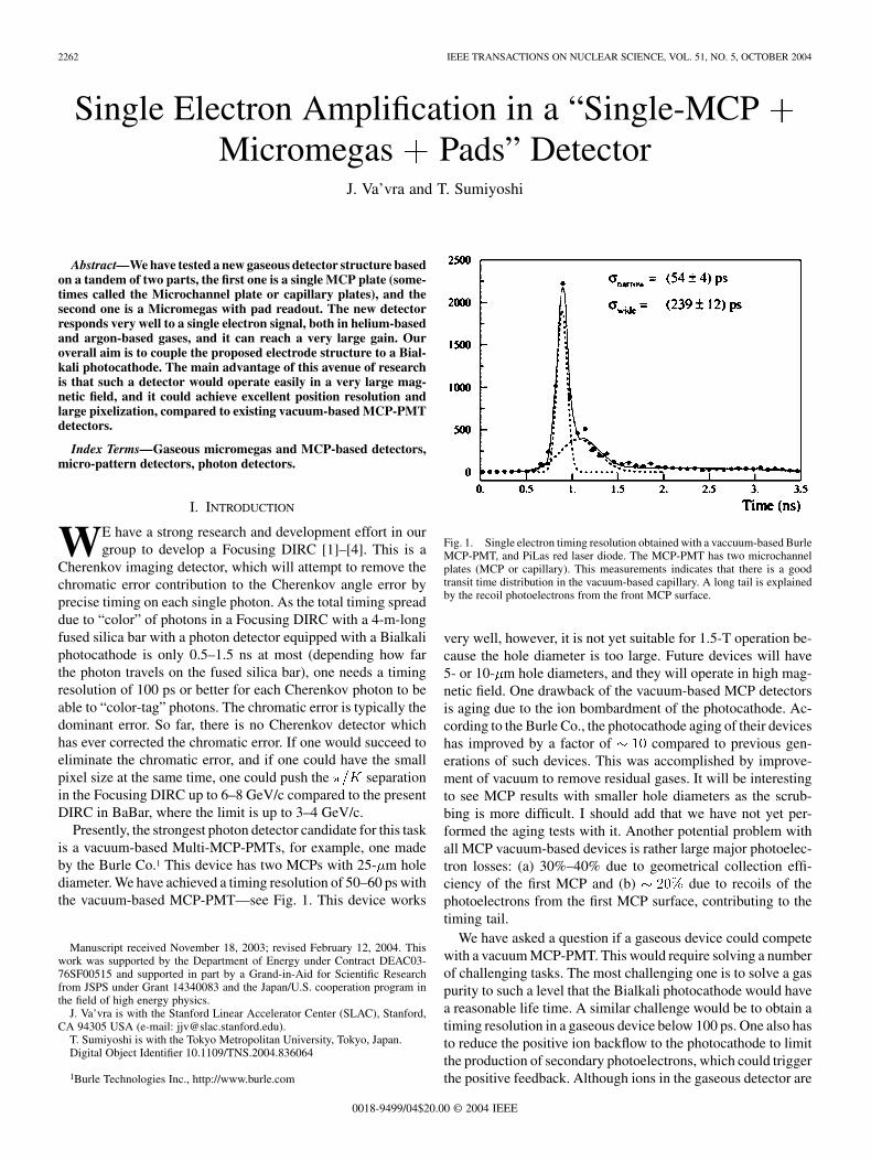
Fig. 6. Typical single electron pulses from this detector together with a QVTgate. A charge integrating amplifier has a gain of 2.7 �V /electron and a shapingtime of 65 ns.
works well to measure single electron pulse height spectra, how-ever, the lamp has a timing jitter that is too large for the precisiontiming measurements at a level of 100 ps.
III. EXPERIMENTAL SETUP
Fig. 5 shows the experimental setup including the detectorvessel and the UV gun. Fig. 6 shows typical single electronpulses observed in the presented detector with an amplifier with2.7- V/electron gain and 65-ns shaping time. We have used thisamplifier only for the purposes to measure the gain and the pulseheight spectra. In the future, we plan to use the same electronicsas is used for the MCP-PMT detector, which is based on theElantek 2075 amplifier, and the constant fraction discriminator[4].
IV. RESULTS
One can achieve a large gain in the He-based gas mixturein this device. For example, Fig. 7 shows single electron pulse
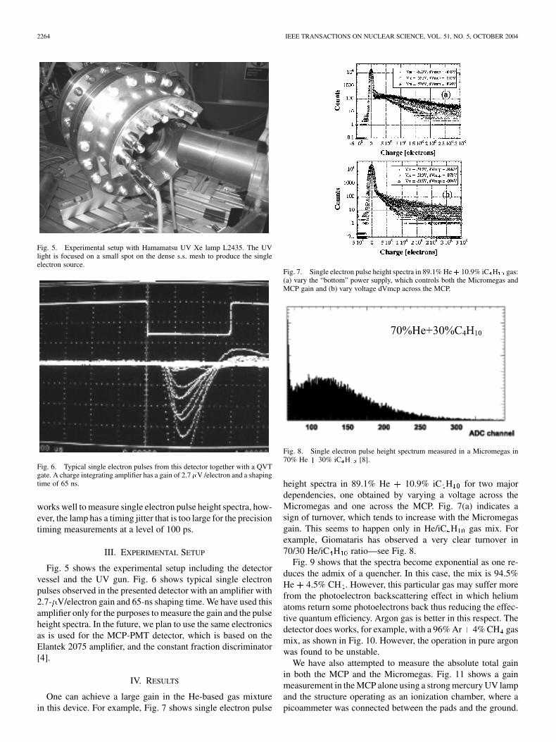
Fig. 7. Single electron pulse height spectra in 89.1% He+ 10.9% iC H gas:(a) vary the “bottom” power supply, which controls both the Micromegas andMCP gain and (b) vary voltage dVmcp across the MCP.
Fig. 8. Single electron pulse height spectrum measured in a Micromegas in70% He + 30% iC H [8].
height spectra in 89.1% He 10.9% iC H for two majordependencies, one obtained by varying a voltage across theMicromegas and one across the MCP. Fig. 7(a) indicates asign of turnover, which tends to increase with the Micromegasgain. This seems to happen only in He/iC H gas mix. Forexample, Giomataris has observed a very clear turnover in70/30 He/iC H ratio—see Fig. 8.
Fig. 9 shows that the spectra become exponential as one re-duces the admix of a quencher. In this case, the mix is 94.5%He 4.5% CH . However, this particular gas may suffer morefrom the photoelectron backscattering effect in which heliumatoms return some photoelectrons back thus reducing the effec-tive quantum efficiency. Argon gas is better in this respect. Thedetector does works, for example, with a 96% Ar 4% CH gasmix, as shown in Fig. 10. However, the operation in pure argonwas found to be unstable.
We have also attempted to measure the absolute total gainin both the MCP and the Micromegas. Fig. 11 shows a gainmeasurement in the MCP alone using a strong mercury UV lampand the structure operating as an ionization chamber, where apicoammeter was connected between the pads and the ground.

VA’VRA AND SUMIYOSHI: SINGLE ELECTRON AMPLIFICATION IN A “SINGLE-MCP MICROMEGAS PADS” DETECTOR 2265
Fig. 9. Single electron pulse height spectra in 94.5% He + 4.5% CH gas.
Fig. 10. Single electron pulse height spectra in 96% Ar+ 4% CH gas.
Fig. 11. Absolute gain measurement in MCP in 94.5% He + 4.5% CH gas.The MCP was in collection mode and the light source was a strong Mercurylamp. A gain increase by a factor of � 15 every 100 volts was observed. Asimilar gain was measured in the Micromegas in the same gas.
The gas gain in 94.5% He 5.5% CH increased by a factorfor every 100 V across the capillary. A similar result was
obtained when measuring the gain in the Micromegas alone.The conditions in the above tests vary, but typically we
would run the detector with the following electric fields:V/cm, kV/cm,
up to 10 kV/cm, and up to 50 kV/cm,corresponding to an average gain of a .
The charge can stay on insulators, such as glass or Kapton,for a long time. Therefore, we wanted to know how long it takes
Fig. 12. The charging effects in the structure was measured using a strongMercury lamp creating a standing current of 350 nA, which was suddenlyinterrupted to measure the discharging time constant. We measure a timeconstant of � 50 s for the presented detector, and this is to be compared to� 85 s, which was measured for the Quadruple-GEM detector [9].
to bleed it away after the detector was subject to a strong lightfrom a mercury lamp, creating a current of nA. The dis-charge time constant was measured by interrupting the light andfollowing the current decay with a picoammeter connected be-tween the pads and the ground. Fig. 12 shows that the dischargetime constant is s. For comparison, the same measurementwith the Quadruple-GEM yielded a time constant of s [9].The discharge time constant is dominated by the resistivity ofthe glass or Kapton, i.e., for example, the effect of the resis-tance divider is negligible. In both cases, no pumping was doneto remove water from the insulator surfaces, and the detectorwas typically under a gas flow 1–2 weeks only.
V. DISCUSSION
Our primary goal was to see if we can achieve the timing res-olution of less than 100 ps per single photon. We have attemptedto create the single electrons with either red or blue Pilas laserdiode striking the dense s.s. mesh at the beginning of the driftfiled, hoping to trigger the double-photon Photoelectric effect.We have not accomplished this, presumably because the laserdiodes were not powerful enough. In absence of the direct mea-surement, we will attempt to argue at least theoretically. Let’sassume that the capillary has an average gain of 5. We will usea simple formula expressing the expected timing resolution as
, where , is themean free path ( is the Townsend coefficient) and is theelectron drift velocity in the Micromegas at kV/cm. Usingthe Magboltz–Monte program [10], one obtains psfor a 95% He 5% CH gas. However, the avalanche fluctua-tions, which are not included in the simple formula, will makethe resolution worse. Nevertheless, this simple theoretical argu-ment seems to be consistent with a measurement using a singleMicromegas, which achieved a timing resolution of 200–300 psper single photon with a simple leading-edge electronics [6].
Immediately after the IEEE presentation, Bo Yu (BNL) sug-gested in a private discussion to eliminate the Micromegas bycreating a small gap between the MCP and the pads and operatethis gap as a parallel-plate chamber [11]. This would definitelyincrease the charge transfer from the MCP to the Micromegas,and also simplify the structure. However, it would also increase
2266 IEEE TRANSACTIONS ON NUCLEAR SCIENCE, VOL. 51, NO. 5, OCTOBER 2004
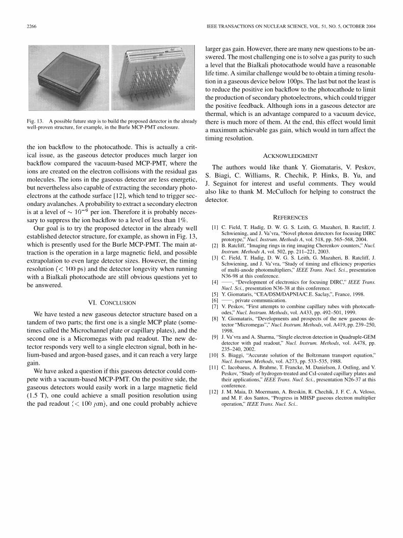
Fig. 13. A possible future step is to build the proposed detector in the alreadywell-proven structure, for example, in the Burle MCP-PMT enclosure.
the ion backflow to the photocathode. This is actually a crit-ical issue, as the gaseous detector produces much larger ionbackflow compared the vacuum-based MCP-PMT, where theions are created on the electron collisions with the residual gasmolecules. The ions in the gaseous detector are less energetic,but nevertheless also capable of extracting the secondary photo-electrons at the cathode surface [12], which tend to trigger sec-ondary avalanches. A probability to extract a secondary electronis at a level of per ion. Therefore it is probably neces-sary to suppress the ion backflow to a level of less than 1%.
Our goal is to try the proposed detector in the already wellestablished detector structure, for example, as shown in Fig. 13,which is presently used for the Burle MCP-PMT. The main at-traction is the operation in a large magnetic field, and possibleextrapolation to even large detector sizes. However, the timingresolution ps and the detector longevity when runningwith a Bialkali photocathode are still obvious questions yet tobe answered.
VI. CONCLUSION
We have tested a new gaseous detector structure based on atandem of two parts; the first one is a single MCP plate (some-times called the Microchannel plate or capillary plates), and thesecond one is a Micromegas with pad readout. The new de-tector responds very well to a single electron signal, both in he-lium-based and argon-based gases, and it can reach a very largegain.
We have asked a question if this gaseous detector could com-pete with a vacuum-based MCP-PMT. On the positive side, thegaseous detectors would easily work in a large magnetic field(1.5 T), one could achieve a small position resolution usingthe pad readout m , and one could probably achieve
larger gas gain. However, there are many new questions to be an-swered. The most challenging one is to solve a gas purity to sucha level that the Bialkali photocathode would have a reasonablelife time. A similar challenge would be to obtain a timing resolu-tion in a gaseous device below 100ps. The last but not the least isto reduce the positive ion backflow to the photocathode to limitthe production of secondary photoelectrons, which could triggerthe positive feedback. Although ions in a gaseous detector arethermal, which is an advantage compared to a vacuum device,there is much more of them. At the end, this effect would limita maximum achievable gas gain, which would in turn affect thetiming resolution.
ACKNOWLEDGMENT
The authors would like thank Y. Giomataris, V. Peskov,S. Biagi, C. Williams, R. Chechik, P. Hinks, B. Yu, andJ. Seguinot for interest and useful comments. They wouldalso like to thank M. McCulloch for helping to construct thedetector.
REFERENCES
[1] C. Field, T. Hadig, D. W. G. S. Leith, G. Mazaheri, B. Ratcliff, J.Schwiening, and J. Va’vra, “Novel photon detectors for focusing DIRCprototype,” Nucl. Instrum. Methods A, vol. 518, pp. 565–568, 2004.
[2] B. Ratcliff, “Imaging rings in ring imaging Cherenkov counters,” Nucl.Instrum. Methods A, vol. 502, pp. 211–221, 2003.
[3] C. Field, T. Hadig, D. W. G. S. Leith, G. Mazaheri, B. Ratcliff, J.Schwiening, and J. Va’vra, “Study of timing and efficiency propertiesof multi-anode photomultipliers,” IEEE Trans. Nucl. Sci., presentationN36-98 at this conference.
[4] , “Development of electronics for focusing DIRC,” IEEE Trans.Nucl. Sci., presentation N36-38 at this conference.
[5] Y. Giomataris, “CEA/DSM/DAPNIA/C.E. Saclay,”, France, 1998.[6] , private communication.[7] V. Peskov, “First attempts to combine capillary tubes with photocath-
odes,” Nucl. Instrum. Methods, vol. A433, pp. 492–501, 1999.[8] Y. Giomataris, “Developments and prospects of the new gaseous de-
tector “Micromegas”,” Nucl. Instrum. Methods, vol. A419, pp. 239–250,1998.
[9] J. Va’vra and A. Sharma, “Single electron detection in Quadruple-GEMdetector with pad readout,” Nucl. Instrum. Methods, vol. A478, pp.235–240, 2002.
[10] S. Biaggi, “Accurate solution of the Boltzmann transport equation,”Nucl. Instrum. Methods, vol. A273, pp. 533–535, 1988.
[11] C. Iacobaeus, A. Brahme, T. Francke, M. Danielson, J. Ostling, and V.Peskov, “Study of hydrogen-treated and CsI-coated capillary plates andtheir applications,” IEEE Trans. Nucl. Sci., presentation N26-37 at thisconference.
[12] J. M. Maia, D. Moermann, A. Breskin, R. Chechik, J. F. C. A. Veloso,and M. F. dos Santos, “Progress in MHSP gaseous electron multiplieroperation,” IEEE Trans. Nucl. Sci..