IEEE TRANSACTIONS ON INDUSTRIAL ELECTRONICS, VOL. 51, …
13
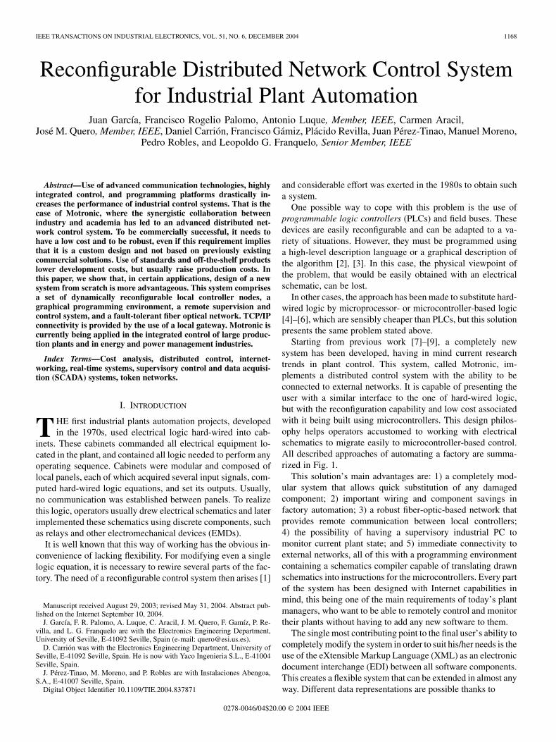
IEEE TRANSACTIONS ON INDUSTRIAL ELECTRONICS, VOL. 51, NO. 6, DECEMBER 2004 1168 Reconfigurable Distributed Network Control System for Industrial Plant Automation Juan García, Francisco Rogelio Palomo, Antonio Luque, Member, IEEE, Carmen Aracil, José M. Quero, Member, IEEE, Daniel Carrión, Francisco Gámiz, Plácido Revilla, Juan Pérez-Tinao, Manuel Moreno, Pedro Robles, and Leopoldo G. Franquelo, Senior Member, IEEE Abstract—Use of advanced communication technologies, highly integrated control, and programming platforms drastically in- creases the performance of industrial control systems. That is the case of Motronic, where the synergistic collaboration between industry and academia has led to an advanced distributed net- work control system. To be commercially successful, it needs to have a low cost and to be robust, even if this requirement implies that it is a custom design and not based on previously existing commercial solutions. Use of standards and off-the-shelf products lower development costs, but usually raise production costs. In this paper, we show that, in certain applications, design of a new system from scratch is more advantageous. This system comprises a set of dynamically reconfigurable local controller nodes, a graphical programming environment, a remote supervision and control system, and a fault-tolerant fiber optical network. TCP/IP connectivity is provided by the use of a local gateway. Motronic is currently being applied in the integrated control of large produc- tion plants and in energy and power management industries. Index Terms—Cost analysis, distributed control, internet- working, real-time systems, supervisory control and data acquisi- tion (SCADA) systems, token networks. I. INTRODUCTION T HE first industrial plants automation projects, developed in the 1970s, used electrical logic hard-wired into cab- inets. These cabinets commanded all electrical equipment lo- cated in the plant, and contained all logic needed to perform any operating sequence. Cabinets were modular and composed of local panels, each of which acquired several input signals, com- puted hard-wired logic equations, and set its outputs. Usually, no communication was established between panels. To realize this logic, operators usually drew electrical schematics and later implemented these schematics using discrete components, such as relays and other electromechanical devices (EMDs). It is well known that this way of working has the obvious in- convenience of lacking flexibility. For modifying even a single logic equation, it is necessary to rewire several parts of the fac- tory. The need of a reconfigurable control system then arises [1] Manuscript received August 29, 2003; revised May 31, 2004. Abstract pub- lished on the Internet September 10, 2004. J. García, F. R. Palomo, A. Luque, C. Aracil, J. M. Quero, F. Gamíz, P. Re- villa, and L. G. Franquelo are with the Electronics Engineering Department, University of Seville, E-41092 Seville, Spain (e-mail: [email protected]). D. Carrión was with the Electronics Engineering Department, University of Seville, E-41092 Seville, Spain. He is now with Yaco Ingenieria S.L., E-41004 Seville, Spain. J. Pérez-Tinao, M. Moreno, and P. Robles are with Instalaciones Abengoa, S.A., E-41007 Seville, Spain. Digital Object Identifier 10.1109/TIE.2004.837871 and considerable effort was exerted in the 1980s to obtain such a system. One possible way to cope with this problem is the use of programmable logic controllers (PLCs) and field buses. These devices are easily reconfigurable and can be adapted to a va- riety of situations. However, they must be programmed using a high-level description language or a graphical description of the algorithm [2], [3]. In this case, the physical viewpoint of the problem, that would be easily obtained with an electrical schematic, can be lost. In other cases, the approach has been made to substitute hard- wired logic by microprocessor- or microcontroller-based logic [4]–[6], which are sensibly cheaper than PLCs, but this solution presents the same problem stated above. Starting from previous work [7]–[9], a completely new system has been developed, having in mind current research trends in plant control. This system, called Motronic, im- plements a distributed control system with the ability to be connected to external networks. It is capable of presenting the user with a similar interface to the one of hard-wired logic, but with the reconfiguration capability and low cost associated with it being built using microcontrollers. This design philos- ophy helps operators accustomed to working with electrical schematics to migrate easily to microcontroller-based control. All described approaches of automating a factory are summa- rized in Fig. 1. This solution’s main advantages are: 1) a completely mod- ular system that allows quick substitution of any damaged component; 2) important wiring and component savings in factory automation; 3) a robust fiber-optic-based network that provides remote communication between local controllers; 4) the possibility of having a supervisory industrial PC to monitor current plant state; and 5) immediate connectivity to external networks, all of this with a programming environment containing a schematics compiler capable of translating drawn schematics into instructions for the microcontrollers. Every part of the system has been designed with Internet capabilities in mind, this being one of the main requirements of today’s plant managers, who want to be able to remotely control and monitor their plants without having to add any new software to them. The single most contributing point to the final user’s ability to completely modify the system in order to suit his/her needs is the use of the eXtensible Markup Language (XML) as an electronic document interchange (EDI) between all software components. This creates a flexible system that can be extended in almost any way. Different data representations are possible thanks to 0278-0046/04$20.00 © 2004 IEEE
Transcript of IEEE TRANSACTIONS ON INDUSTRIAL ELECTRONICS, VOL. 51, …
IEEE TRANSACTIONS ON INDUSTRIAL ELECTRONICS, VOL. 51, NO. 6, DECEMBER 2004 1168
Reconfigurable Distributed Network Control Systemfor Industrial Plant Automation
Juan García, Francisco Rogelio Palomo, Antonio Luque, Member, IEEE, Carmen Aracil,José M. Quero, Member, IEEE, Daniel Carrión, Francisco Gámiz, Plácido Revilla, Juan Pérez-Tinao, Manuel Moreno,
Pedro Robles, and Leopoldo G. Franquelo, Senior Member, IEEE
Abstract—Use of advanced communication technologies, highlyintegrated control, and programming platforms drastically in-creases the performance of industrial control systems. That is thecase of Motronic, where the synergistic collaboration betweenindustry and academia has led to an advanced distributed net-work control system. To be commercially successful, it needs tohave a low cost and to be robust, even if this requirement impliesthat it is a custom design and not based on previously existingcommercial solutions. Use of standards and off-the-shelf productslower development costs, but usually raise production costs. Inthis paper, we show that, in certain applications, design of a newsystem from scratch is more advantageous. This system comprisesa set of dynamically reconfigurable local controller nodes, agraphical programming environment, a remote supervision andcontrol system, and a fault-tolerant fiber optical network. TCP/IPconnectivity is provided by the use of a local gateway. Motronic iscurrently being applied in the integrated control of large produc-tion plants and in energy and power management industries.
Index Terms—Cost analysis, distributed control, internet-working, real-time systems, supervisory control and data acquisi-tion (SCADA) systems, token networks.
I. INTRODUCTION
THE first industrial plants automation projects, developedin the 1970s, used electrical logic hard-wired into cab-
inets. These cabinets commanded all electrical equipment lo-cated in the plant, and contained all logic needed to perform anyoperating sequence. Cabinets were modular and composed oflocal panels, each of which acquired several input signals, com-puted hard-wired logic equations, and set its outputs. Usually,no communication was established between panels. To realizethis logic, operators usually drew electrical schematics and laterimplemented these schematics using discrete components, suchas relays and other electromechanical devices (EMDs).
It is well known that this way of working has the obvious in-convenience of lacking flexibility. For modifying even a singlelogic equation, it is necessary to rewire several parts of the fac-tory. The need of a reconfigurable control system then arises [1]
Manuscript received August 29, 2003; revised May 31, 2004. Abstract pub-lished on the Internet September 10, 2004.
J. García, F. R. Palomo, A. Luque, C. Aracil, J. M. Quero, F. Gamíz, P. Re-villa, and L. G. Franquelo are with the Electronics Engineering Department,University of Seville, E-41092 Seville, Spain (e-mail: [email protected]).
D. Carrión was with the Electronics Engineering Department, University ofSeville, E-41092 Seville, Spain. He is now with Yaco Ingenieria S.L., E-41004Seville, Spain.
J. Pérez-Tinao, M. Moreno, and P. Robles are with Instalaciones Abengoa,S.A., E-41007 Seville, Spain.
Digital Object Identifier 10.1109/TIE.2004.837871
and considerable effort was exerted in the 1980s to obtain sucha system.
One possible way to cope with this problem is the use ofprogrammable logic controllers (PLCs) and field buses. Thesedevices are easily reconfigurable and can be adapted to a va-riety of situations. However, they must be programmed usinga high-level description language or a graphical description ofthe algorithm [2], [3]. In this case, the physical viewpoint ofthe problem, that would be easily obtained with an electricalschematic, can be lost.
In other cases, the approach has been made to substitute hard-wired logic by microprocessor- or microcontroller-based logic[4]–[6], which are sensibly cheaper than PLCs, but this solutionpresents the same problem stated above.
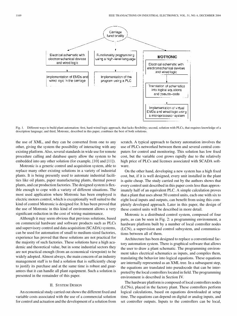
Starting from previous work [7]–[9], a completely newsystem has been developed, having in mind current researchtrends in plant control. This system, called Motronic, im-plements a distributed control system with the ability to beconnected to external networks. It is capable of presenting theuser with a similar interface to the one of hard-wired logic,but with the reconfiguration capability and low cost associatedwith it being built using microcontrollers. This design philos-ophy helps operators accustomed to working with electricalschematics to migrate easily to microcontroller-based control.All described approaches of automating a factory are summa-rized in Fig. 1.
This solution’s main advantages are: 1) a completely mod-ular system that allows quick substitution of any damagedcomponent; 2) important wiring and component savings infactory automation; 3) a robust fiber-optic-based network thatprovides remote communication between local controllers;4) the possibility of having a supervisory industrial PC tomonitor current plant state; and 5) immediate connectivity toexternal networks, all of this with a programming environmentcontaining a schematics compiler capable of translating drawnschematics into instructions for the microcontrollers. Every partof the system has been designed with Internet capabilities inmind, this being one of the main requirements of today’s plantmanagers, who want to be able to remotely control and monitortheir plants without having to add any new software to them.
The single most contributing point to the final user’s ability tocompletely modify the system in order to suit his/her needs is theuse of the eXtensible Markup Language (XML) as an electronicdocument interchange (EDI) between all software components.This creates a flexible system that can be extended in almost anyway. Different data representations are possible thanks to
0278-0046/04$20.00 © 2004 IEEE
1169 IEEE TRANSACTIONS ON INDUSTRIAL ELECTRONICS, VOL. 51, NO. 6, DECEMBER 2004
Fig. 1. Different ways to build plant automation: first, hard-wired logic approach, that lacks flexibility; second, solution with PLCs, that requires knowledge of adescription language; and third, Motronic, described in this paper, combines the best of both solutions.
the use of XML, and they can be converted from one to anyother, giving the system the possibility of interacting with anyexisting platform. Also, several standards in wide use for remoteprocedure calling and database query allow the system to beembedded into any other solution (for example, [10] and [11]).
Motronic is a generic control and acquisition system, able toreplace many other existing solutions in a variety of industrialplants. It is being presently used to automate industrial facili-ties like oil plants, paper manufacturing plants, thermal powerplants, and car production factories. The designed system is flex-ible enough to cope with a variety of different situations. Themost used application where Motronic has been employed iselectric motors control, which is exceptionally well suited to thekind of control Motronic is designed for. It has been proved thatthe use of Motronic in this kind of environment allows a verysignificant reduction in the cost of wiring maintenance.
Although it may seem obvious that previous solutions, basedon commercial hardware and software products such as PLCsand supervisory control and data acquisition (SCADA) systems,can be used for automation of small to medium-sized factories,experience has proved that these solutions are not practical forthe majority of such factories. These solutions have a high aca-demic and theoretical value, but in some industrial sectors theyare not practical enough (from an economical viewpoint) to bewidely adopted. Almost always, the main concern of an industrymanagement staff is to find a solution that is sufficiently cheapto justify its purchase and at the same time is robust and guar-antees that it can handle all plant equipment. Such a solution ispresented in the remainder of this paper.
II. SYSTEM DESIGN
An economical study carried out shows the different fixed andvariable costs associated with the use of a commercial solutionfor control and actuation and the development of a solution from
scratch. A typical approach to factory automation involves theuse of PLCs networked between them and several central com-puters for control and monitoring. This solution has low fixedcost, but the variable cost grows rapidly due to the relativelyhigh price of PLCs and licenses associated with SCADA soft-ware.
On the other hand, developing a new system has a high fixedcost, but, if it is well designed, every unit installed in the plantis quite cheap. The study carried out by the authors shows thatevery control unit described in this paper costs less than approx-imately half of an equivalent PLC. A simple calculation provesthat a plant that uses about 50 control units, each one with six toeight local inputs and outputs, can benefit from using this com-pletely developed approach. Later in this paper, the design ofthese control units will be described in more detail.
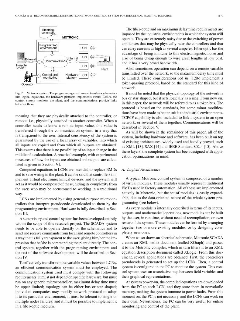
Motronic is a distributed control system, composed of fourparts, as can be seen in Fig. 2: a programming environment, ahardware platform built by a number of local controller nodes(LCN), a supervision and control subsystem, and communica-tions between all of them.
Architecture has been designed to replace a conventional fac-tory automation system. There is graphical software that allowsthe user to draw a plant schematic. The programming environ-ment takes electrical schematics as inputs, and compiles them,translating the behavior into logical equations. These equationsare internally represented as an XML tree. In a subsequent step,the equations are translated into pseudocode that can be inter-preted by the local controllers located in field. The programmingenvironment is described in Section IV.
The hardware platform is composed of local controllers nodes(LCNs), placed in the factory plant. These controllers performlogical calculations, based on equations downloaded at setuptime. The equations can depend on digital or analog inputs, andset controller outputs. Inputs to the controllers can be local,
GARCÍA et al.: RECONFIGURABLE DISTRIBUTED NETWORK CONTROL SYSTEM FOR INDUSTRIAL PLANT AUTOMATION 1170
Fig. 2. Motronic system. The programming environment translates schematicsinto logical equations, the hardware platform implements virtual EMDs, thecontrol system monitors the plant, and the communications provide linksbetween them.
meaning that they are physically attached to the controller, orremote, i.e., physically attached to another controller. When acontroller needs to know a remote input value, this value istransferred through the communication system, in a way thatis transparent to the user. Internal consistency of the system isguaranteed by the use of a local array of variables, into whichall inputs are copied and from which all outputs are obtained.This assures that there is no possibility of an input change in themiddle of a calculation. A practical example, with experimentalmeasures, of how the inputs are obtained and outputs are calcu-lated is given in Section VI.
Computed equations in LCNs are intended to replace EMDsand to save wiring in the plant. It can be said that controllers im-plement virtual electromechanical devices, and the system willact as it would be composed of these, hiding its complexity fromthe user, who may be accustomed to working in a traditionalway.
LCNs are implemented by using general-purpose microcon-trollers that interpret pseudocode downloaded to them by theprogramming environment. Hardware is fully described in Sec-tion III.
A supervisory and control system has been developed entirelywithin the scope of this research project. The SCADA systemneeds to be able to operate directly on the schematics and tosend and receive commands from local and remote controllers ina way that is fully transparent to the user, giving him/her the im-pression that he/she is commanding the plant directly. The con-trol system, together with the programming environment andthe rest of the software development, will be described in Sec-tion IV.
To effectively transfer remote variable values between LCNs,an efficient communication system must be employed. Thecommunication system used must comply with the followingrequirements: it must not depend on specific hardware, but mustrun on any generic microcontroller; maximum delay time mustbe upper limited; topology can be either bus or star shaped;individual companies may modify network protocol to adaptit to its particular environment; it must be tolerant to single ormultiple nodes failures; and it must be possible to implement itin a fiber-optic medium.
The fiber-optic and on maximum delay time requirements areimposed by the industrial environments in which the system willoperate. They are extremely noisy due to the switching of powerappliances that may be physically near the controllers and thatcan carry currents as high as several amperes. Fiber optic has theadvantage of being immune to this electromagnetic noise andalso of being cheap enough to wire great lengths at low cost,and it has a very broad bandwidth.
Also, sometimes operation can depend on a remote variabletransmitted over the network, so the maximum delay time mustbe limited. These considerations led us [12]to implement atoken-passing protocol, based on the standard for this kind ofnetwork.
It must be noted that the physical topology of the network isbus or star shaped, but it acts logically as a ring. From now on,in this paper, the network will be referred to as a token bus. Theprotocol is based on the standards, but some minor modifica-tions have been made to better suit it to industrial environments.TCP/IP capability is also included to link a system to an opennetwork, or several of them together. Communications will bedescribed in Section V.
As will be shown in the remainder of this paper, all of thesystem, including hardware and software, has been built on topof existing architectures, widely used and heavily proved, suchas XML [13], SAX [14] and IEEE Standard 802.4 [15]. Abovethese layers, the complete system has been designed with appli-cation optimizations in mind.
A. Logical Architecture
A typical Motronic control system is composed of a numberof virtual modules. These modules usually represent traditionalEMDs used in factory automation. All of these are implementednatively in Motronic, but the set of modules is easily expand-able, due to the data-oriented nature of the whole system pro-gramming (see below).
As every module is internally described in terms of its inputs,outputs, and mathematical operations, new modules can be builtby the user, in run time, without need of recompilation, or evenrestart of the system. These modules can be formed by arrangingtogether two or more existing modules, or by designing com-pletely new ones.
When a user draws an electrical schematic, Motronic SCADAcreates an XML netlist document (called XGraph) and passesit to the Motronic compiler, which in turn filters it to an XMLequation description document called XLogic. From this doc-ument, several applications are obtained. First, the controllerspseudocode is generated to set up the LCNs. Then, a controlsystem is configured in the PC to monitor the system. This con-trol system uses an associative map between field variables andtheir graphical representations.
At system power-on, the compiled equations are downloadedfrom the PC to each LCN, and they store them in nonvolatilememory, making the system immune to power faults. From thismoment on, the PC is not necessary, and the LCNs can work ontheir own. Nevertheless, the PC can be very useful for onlinemonitoring and control of the plant.
1171 IEEE TRANSACTIONS ON INDUSTRIAL ELECTRONICS, VOL. 51, NO. 6, DECEMBER 2004
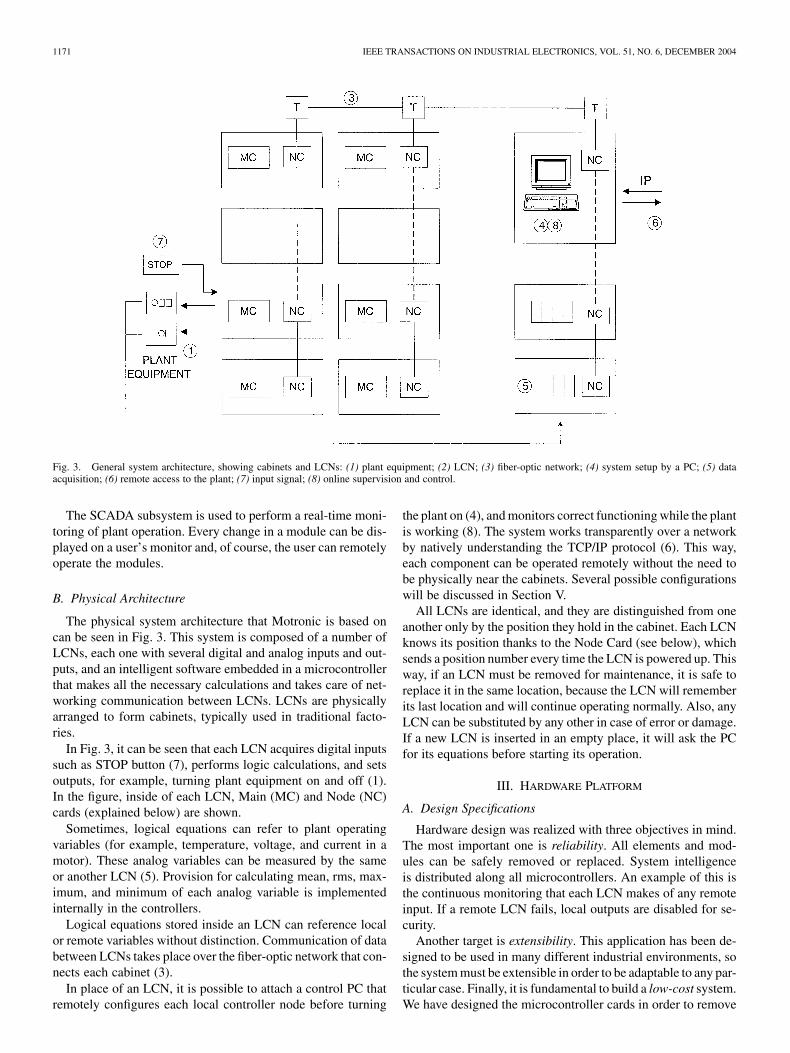
Fig. 3. General system architecture, showing cabinets and LCNs: (1) plant equipment; (2) LCN; (3) fiber-optic network; (4) system setup by a PC; (5) dataacquisition; (6) remote access to the plant; (7) input signal; (8) online supervision and control.
The SCADA subsystem is used to perform a real-time moni-toring of plant operation. Every change in a module can be dis-played on a user’s monitor and, of course, the user can remotelyoperate the modules.
B. Physical Architecture
The physical system architecture that Motronic is based oncan be seen in Fig. 3. This system is composed of a number ofLCNs, each one with several digital and analog inputs and out-puts, and an intelligent software embedded in a microcontrollerthat makes all the necessary calculations and takes care of net-working communication between LCNs. LCNs are physicallyarranged to form cabinets, typically used in traditional facto-ries.
In Fig. 3, it can be seen that each LCN acquires digital inputssuch as STOP button (7), performs logic calculations, and setsoutputs, for example, turning plant equipment on and off (1).In the figure, inside of each LCN, Main (MC) and Node (NC)cards (explained below) are shown.
Sometimes, logical equations can refer to plant operatingvariables (for example, temperature, voltage, and current in amotor). These analog variables can be measured by the sameor another LCN (5). Provision for calculating mean, rms, max-imum, and minimum of each analog variable is implementedinternally in the controllers.
Logical equations stored inside an LCN can reference localor remote variables without distinction. Communication of databetween LCNs takes place over the fiber-optic network that con-nects each cabinet (3).
In place of an LCN, it is possible to attach a control PC thatremotely configures each local controller node before turning
the plant on (4), and monitors correct functioning while the plantis working (8). The system works transparently over a networkby natively understanding the TCP/IP protocol (6). This way,each component can be operated remotely without the need tobe physically near the cabinets. Several possible configurationswill be discussed in Section V.
All LCNs are identical, and they are distinguished from oneanother only by the position they hold in the cabinet. Each LCNknows its position thanks to the Node Card (see below), whichsends a position number every time the LCN is powered up. Thisway, if an LCN must be removed for maintenance, it is safe toreplace it in the same location, because the LCN will rememberits last location and will continue operating normally. Also, anyLCN can be substituted by any other in case of error or damage.If a new LCN is inserted in an empty place, it will ask the PCfor its equations before starting its operation.
III. HARDWARE PLATFORM
A. Design Specifications
Hardware design was realized with three objectives in mind.The most important one is reliability. All elements and mod-ules can be safely removed or replaced. System intelligenceis distributed along all microcontrollers. An example of this isthe continuous monitoring that each LCN makes of any remoteinput. If a remote LCN fails, local outputs are disabled for se-curity.
Another target is extensibility. This application has been de-signed to be used in many different industrial environments, sothe system must be extensible in order to be adaptable to any par-ticular case. Finally, it is fundamental to build a low-cost system.We have designed the microcontroller cards in order to remove
GARCÍA et al.: RECONFIGURABLE DISTRIBUTED NETWORK CONTROL SYSTEM FOR INDUSTRIAL PLANT AUTOMATION 1172
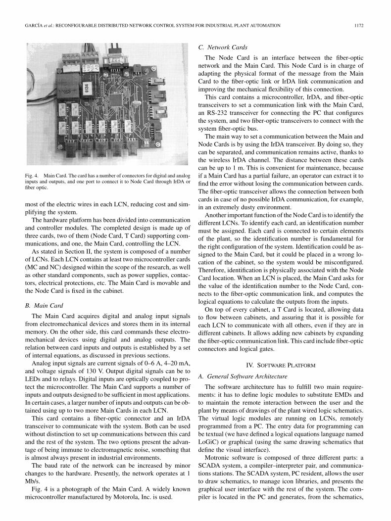
Fig. 4. Main Card. The card has a number of connectors for digital and analoginputs and outputs, and one port to connect it to Node Card through IrDA orfiber optic.
most of the electric wires in each LCN, reducing cost and sim-plifying the system.
The hardware platform has been divided into communicationand controller modules. The completed design is made up ofthree cards, two of them (Node Card, T Card) supporting com-munications, and one, the Main Card, controlling the LCN.
As stated in Section II, the system is composed of a numberof LCNs. Each LCN contains at least two microcontroller cards(MC and NC) designed within the scope of the research, as wellas other standard components, such as power supplies, contac-tors, electrical protections, etc. The Main Card is movable andthe Node Card is fixed in the cabinet.
B. Main Card
The Main Card acquires digital and analog input signalsfrom electromechanical devices and stores them in its internalmemory. On the other side, this card commands these electro-mechanical devices using digital and analog outputs. Therelation between card inputs and outputs is established by a setof internal equations, as discussed in previous sections.
Analog input signals are current signals of 0–6 A, 4–20 mA,and voltage signals of 130 V. Output digital signals can be toLEDs and to relays. Digital inputs are optically coupled to pro-tect the microcontroller. The Main Card supports a number ofinputs and outputs designed to be sufficient in most applications.In certain cases, a larger number of inputs and outputs can be ob-tained using up to two more Main Cards in each LCN.
This card contains a fiber-optic connector and an IrDAtransceiver to communicate with the system. Both can be usedwithout distinction to set up communications between this cardand the rest of the system. The two options present the advan-tage of being immune to electromagnetic noise, something thatis almost always present in industrial environments.
The baud rate of the network can be increased by minorchanges to the hardware. Presently, the network operates at 1Mb/s.
Fig. 4 is a photograph of the Main Card. A widely knownmicrocontroller manufactured by Motorola, Inc. is used.
C. Network Cards
The Node Card is an interface between the fiber-opticnetwork and the Main Card. This Node Card is in charge ofadapting the physical format of the message from the MainCard to the fiber-optic link or IrDA link communication andimproving the mechanical flexibility of this connection.
This card contains a microcontroller, IrDA, and fiber-optictransceivers to set a communication link with the Main Card,an RS-232 transceiver for connecting the PC that configuresthe system, and two fiber-optic transceivers to connect with thesystem fiber-optic bus.
The main way to set a communication between the Main andNode Cards is by using the IrDA transceiver. By doing so, theycan be separated, and communication remains active, thanks tothe wireless IrDA channel. The distance between these cardscan be up to 1 m. This is convenient for maintenance, becauseif a Main Card has a partial failure, an operator can extract it tofind the error without losing the communication between cards.The fiber-optic transceiver allows the connection between bothcards in case of no possible IrDA communication, for example,in an extremely dusty environment.
Another important function of the Node Card is to identify thedifferent LCNs. To identify each card, an identification numbermust be assigned. Each card is connected to certain elementsof the plant, so the identification number is fundamental forthe right configuration of the system. Identification could be as-signed to the Main Card, but it could be placed in a wrong lo-cation of the cabinet, so the system would be misconfigured.Therefore, identification is physically associated with the NodeCard location. When an LCN is placed, the Main Card asks forthe value of the identification number to the Node Card, con-nects to the fiber-optic communication link, and computes thelogical equations to calculate the outputs from the inputs.
On top of every cabinet, a T Card is located, allowing datato flow between cabinets, and assuring that it is possible foreach LCN to communicate with all others, even if they are indifferent cabinets. It allows adding new cabinets by expandingthe fiber-optic communication link. This card include fiber-opticconnectors and logical gates.
IV. SOFTWARE PLATFORM
A. General Software Architecture
The software architecture has to fulfill two main require-ments: it has to define logic modules to substitute EMDs andto maintain the remote interaction between the user and theplant by means of drawings of the plant wired logic schematics.The virtual logic modules are running on LCNs, remotelyprogrammed from a PC. The entry data for programming canbe textual (we have defined a logical equations language namedLoGiC) or graphical (using the same drawing schematics thatdefine the visual interface).
Motronic software is composed of three different parts: aSCADA system, a compiler–interpreter pair, and communica-tions stations. The SCADA system, PC resident, allows the userto draw schematics, to manage icon libraries, and presents thegraphical user interface with the rest of the system. The com-piler is located in the PC and generates, from the schematics,
1173 IEEE TRANSACTIONS ON INDUSTRIAL ELECTRONICS, VOL. 51, NO. 6, DECEMBER 2004
the pseudocode that is later sent to the interpreter residing inthe LCNs. Finally, the communications stations are in charge ofmanaging the message passing between nodes in the network(in the case of the LCNs and PC) and between the network pro-tocols that are supported (only in the PC).
For the planning of the architecture we utilize four designphilosophies: object-oriented programming (OOP) for theSCADA, data-oriented programming (DOP) for the SCADAbuilder and for the virtual module compiler, real-time program-ming (RTP) for the whole communications procedure (on IPand on token bus, with gatewaying between the protocols),and data-flow-oriented programming (DFOP) for the softwarerunning on the LCNs.
Use of the DOP philosophy in industrial software is a re-cent innovation. The necessity of including a compiler to trans-form the LoGiC program or the drawn electrical schematicsinto pseudocode recommended the definition of a virtual doc-ument pipeline processing, so the DOP philosophy was the log-ical choice. The DOP paradigm is also used in several other partsof the system.
The DOP data format is XML. The W3 Consortium has nor-malized XML as a data description language [13]. The XMLdocuments are sequential ASCII files in human-readable format.This feature, and its inherent hierarchical structure make it idealfor data storage and recovery in a way that is easily modifiablewithout having to recompile anything. This is one of the mostinteresting advantages of the system described here, and it al-lows one to develop the software platform and future additionsto it with little effort.
Each XML document has to be processed (a task usuallyknown as parsing) to incorporate the data contents into a clientapplication. For XML processing we use the event-driven ap-proach using an event-driven parser, based on SAX [14], calledexpat [16]. An event-driven parser helps the application to bevery fast and economical in memory resources.
XML as a data format is intensively used by the Motronicapplication as text, as a serialization of other data structures,and as a logical tree. Several dialects of XML are used inMotronic: XIconLib, XGraph, and XLogic, and there is a di-alect transformation from XGraph to XLogic in the compilingpipeline. XIconLib is used for external description of objectsand system configuration, XGraph describes schematics andsynoptics drawings and XLogic describes logical equations inpostfix notation. Serialization of these dialects is also carriedout by the software to store the data in computer files.
The inverse process, object reconstruction, is made throughfactory classes [17], [18]. The pattern of the objective class isembedded into its respective factory class. From the entry data,in XML format (for example, XIconLib), the factory class re-constructs the objective class using the pattern as a template.Object reconstruction is useful to increase application function-alities by adding new objects (of known patterns embedded inapplication factory classes) through their data description.
The programmer can add new patterned objects to theMotronic object library by writing documents in the XIconLibdialect. This is a modular mechanism to increase Motronicfunctionalities without recompiling the whole application. Atthe start of the Motronic application, an initialization sequence
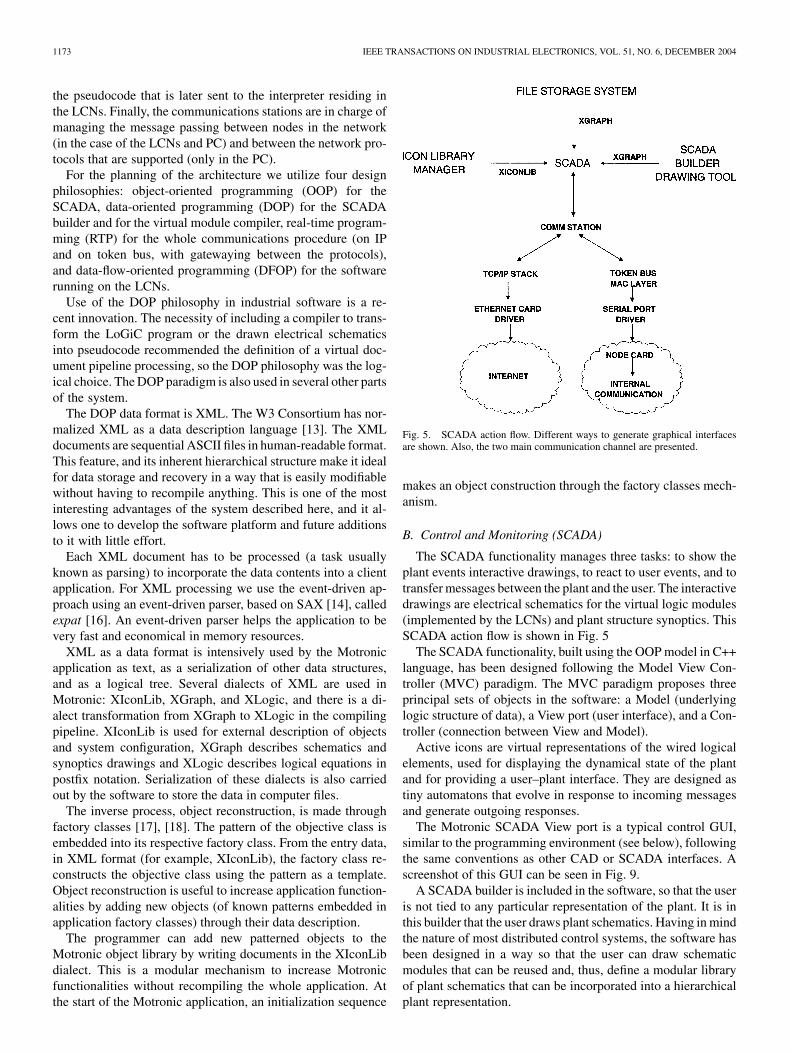
Fig. 5. SCADA action flow. Different ways to generate graphical interfacesare shown. Also, the two main communication channel are presented.
makes an object construction through the factory classes mech-anism.
B. Control and Monitoring (SCADA)
The SCADA functionality manages three tasks: to show theplant events interactive drawings, to react to user events, and totransfer messages between the plant and the user. The interactivedrawings are electrical schematics for the virtual logic modules(implemented by the LCNs) and plant structure synoptics. ThisSCADA action flow is shown in Fig. 5
The SCADA functionality, built using the OOP model in C++language, has been designed following the Model View Con-troller (MVC) paradigm. The MVC paradigm proposes threeprincipal sets of objects in the software: a Model (underlyinglogic structure of data), a View port (user interface), and a Con-troller (connection between View and Model).
Active icons are virtual representations of the wired logicalelements, used for displaying the dynamical state of the plantand for providing a user–plant interface. They are designed astiny automatons that evolve in response to incoming messagesand generate outgoing responses.
The Motronic SCADA View port is a typical control GUI,similar to the programming environment (see below), followingthe same conventions as other CAD or SCADA interfaces. Ascreenshot of this GUI can be seen in Fig. 9.
A SCADA builder is included in the software, so that the useris not tied to any particular representation of the plant. It is inthis builder that the user draws plant schematics. Having in mindthe nature of most distributed control systems, the software hasbeen designed in a way so that the user can draw schematicmodules that can be reused and, thus, define a modular libraryof plant schematics that can be incorporated into a hierarchicalplant representation.
GARCÍA et al.: RECONFIGURABLE DISTRIBUTED NETWORK CONTROL SYSTEM FOR INDUSTRIAL PLANT AUTOMATION 1174
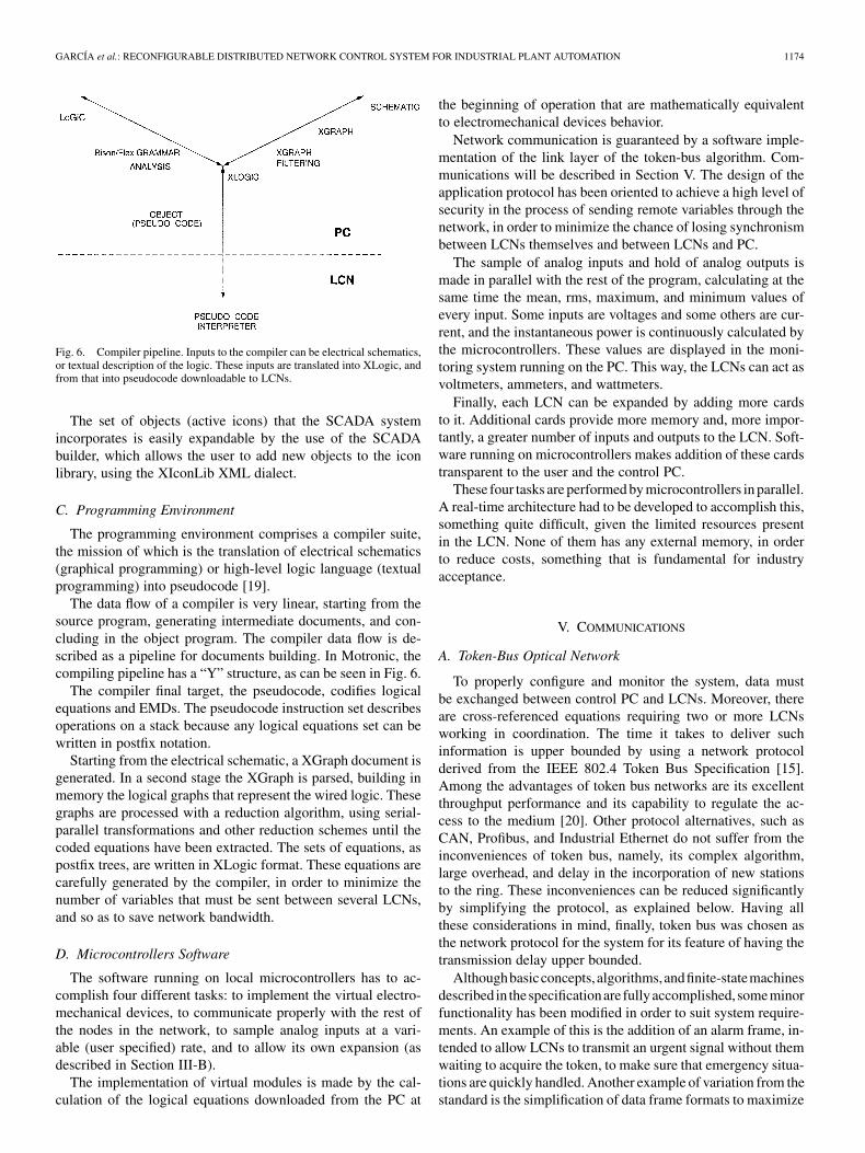
Fig. 6. Compiler pipeline. Inputs to the compiler can be electrical schematics,or textual description of the logic. These inputs are translated into XLogic, andfrom that into pseudocode downloadable to LCNs.
The set of objects (active icons) that the SCADA systemincorporates is easily expandable by the use of the SCADAbuilder, which allows the user to add new objects to the iconlibrary, using the XIconLib XML dialect.
C. Programming Environment
The programming environment comprises a compiler suite,the mission of which is the translation of electrical schematics(graphical programming) or high-level logic language (textualprogramming) into pseudocode [19].
The data flow of a compiler is very linear, starting from thesource program, generating intermediate documents, and con-cluding in the object program. The compiler data flow is de-scribed as a pipeline for documents building. In Motronic, thecompiling pipeline has a “Y” structure, as can be seen in Fig. 6.
The compiler final target, the pseudocode, codifies logicalequations and EMDs. The pseudocode instruction set describesoperations on a stack because any logical equations set can bewritten in postfix notation.
Starting from the electrical schematic, a XGraph document isgenerated. In a second stage the XGraph is parsed, building inmemory the logical graphs that represent the wired logic. Thesegraphs are processed with a reduction algorithm, using serial-parallel transformations and other reduction schemes until thecoded equations have been extracted. The sets of equations, aspostfix trees, are written in XLogic format. These equations arecarefully generated by the compiler, in order to minimize thenumber of variables that must be sent between several LCNs,and so as to save network bandwidth.
D. Microcontrollers Software
The software running on local microcontrollers has to ac-complish four different tasks: to implement the virtual electro-mechanical devices, to communicate properly with the rest ofthe nodes in the network, to sample analog inputs at a vari-able (user specified) rate, and to allow its own expansion (asdescribed in Section III-B).
The implementation of virtual modules is made by the cal-culation of the logical equations downloaded from the PC at
the beginning of operation that are mathematically equivalentto electromechanical devices behavior.
Network communication is guaranteed by a software imple-mentation of the link layer of the token-bus algorithm. Com-munications will be described in Section V. The design of theapplication protocol has been oriented to achieve a high level ofsecurity in the process of sending remote variables through thenetwork, in order to minimize the chance of losing synchronismbetween LCNs themselves and between LCNs and PC.
The sample of analog inputs and hold of analog outputs ismade in parallel with the rest of the program, calculating at thesame time the mean, rms, maximum, and minimum values ofevery input. Some inputs are voltages and some others are cur-rent, and the instantaneous power is continuously calculated bythe microcontrollers. These values are displayed in the moni-toring system running on the PC. This way, the LCNs can act asvoltmeters, ammeters, and wattmeters.
Finally, each LCN can be expanded by adding more cardsto it. Additional cards provide more memory and, more impor-tantly, a greater number of inputs and outputs to the LCN. Soft-ware running on microcontrollers makes addition of these cardstransparent to the user and the control PC.
These four tasks are performed by microcontrollers in parallel.A real-time architecture had to be developed to accomplish this,something quite difficult, given the limited resources presentin the LCN. None of them has any external memory, in orderto reduce costs, something that is fundamental for industryacceptance.
V. COMMUNICATIONS
A. Token-Bus Optical Network
To properly configure and monitor the system, data mustbe exchanged between control PC and LCNs. Moreover, thereare cross-referenced equations requiring two or more LCNsworking in coordination. The time it takes to deliver suchinformation is upper bounded by using a network protocolderived from the IEEE 802.4 Token Bus Specification [15].Among the advantages of token bus networks are its excellentthroughput performance and its capability to regulate the ac-cess to the medium [20]. Other protocol alternatives, such asCAN, Profibus, and Industrial Ethernet do not suffer from theinconveniences of token bus, namely, its complex algorithm,large overhead, and delay in the incorporation of new stationsto the ring. These inconveniences can be reduced significantlyby simplifying the protocol, as explained below. Having allthese considerations in mind, finally, token bus was chosen asthe network protocol for the system for its feature of having thetransmission delay upper bounded.
Althoughbasicconcepts,algorithms,andfinite-statemachinesdescribed in thespecificationare fullyaccomplished, someminorfunctionality has been modified in order to suit system require-ments. An example of this is the addition of an alarm frame, in-tended to allow LCNs to transmit an urgent signal without themwaiting to acquire the token, to make sure that emergency situa-tions are quickly handled. Another example of variation from thestandard is the simplification of data frame formats to maximize
1175 IEEE TRANSACTIONS ON INDUSTRIAL ELECTRONICS, VOL. 51, NO. 6, DECEMBER 2004
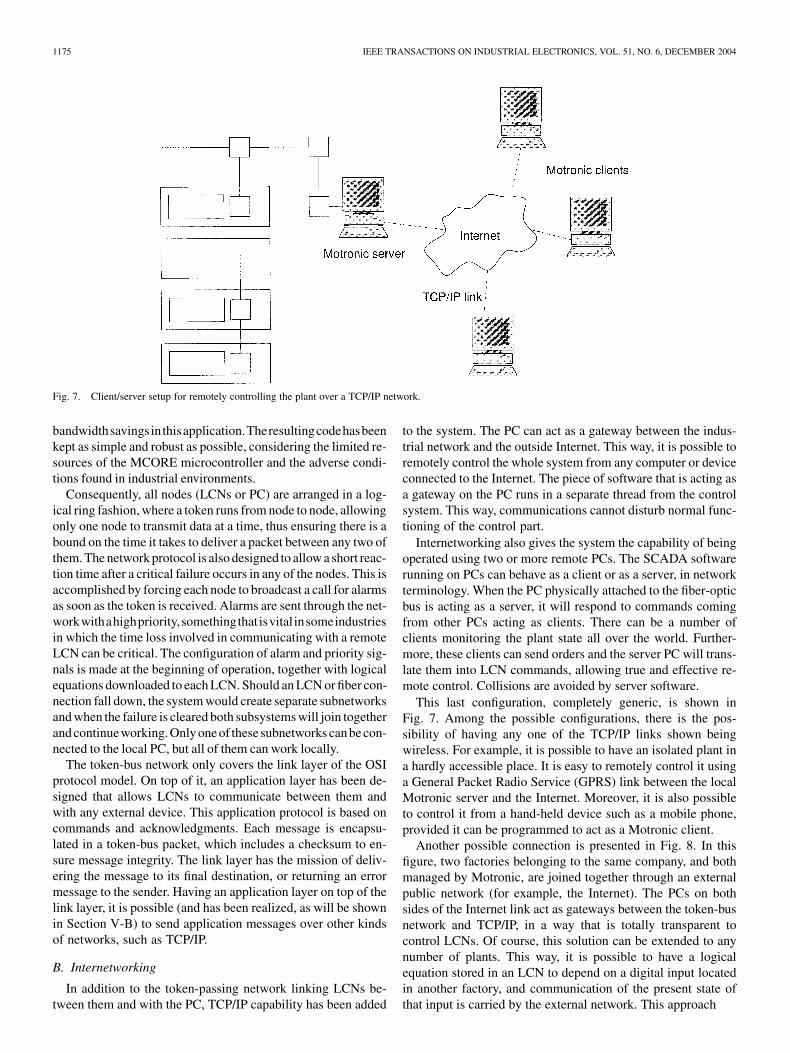
Fig. 7. Client/server setup for remotely controlling the plant over a TCP/IP network.
bandwidthsavingsinthisapplication.Theresultingcodehasbeenkept as simple and robust as possible, considering the limited re-sources of the MCORE microcontroller and the adverse condi-tions found in industrial environments.
Consequently, all nodes (LCNs or PC) are arranged in a log-ical ring fashion, where a token runs from node to node, allowingonly one node to transmit data at a time, thus ensuring there is abound on the time it takes to deliver a packet between any two ofthem. The network protocol is also designed to allow a short reac-tion time after a critical failure occurs in any of the nodes. This isaccomplished by forcing each node to broadcast a call for alarmsas soon as the token is received. Alarms are sent through the net-workwithahighpriority,somethingthat isvital insomeindustriesin which the time loss involved in communicating with a remoteLCN can be critical. The configuration of alarm and priority sig-nals is made at the beginning of operation, together with logicalequations downloaded to each LCN. Should an LCN or fiber con-nection fall down, the system would create separate subnetworksand when the failure is cleared both subsystems will join togetherand continue working. Only one of these subnetworks canbe con-nected to the local PC, but all of them can work locally.
The token-bus network only covers the link layer of the OSIprotocol model. On top of it, an application layer has been de-signed that allows LCNs to communicate between them andwith any external device. This application protocol is based oncommands and acknowledgments. Each message is encapsu-lated in a token-bus packet, which includes a checksum to en-sure message integrity. The link layer has the mission of deliv-ering the message to its final destination, or returning an errormessage to the sender. Having an application layer on top of thelink layer, it is possible (and has been realized, as will be shownin Section V-B) to send application messages over other kindsof networks, such as TCP/IP.
B. Internetworking
In addition to the token-passing network linking LCNs be-tween them and with the PC, TCP/IP capability has been added
to the system. The PC can act as a gateway between the indus-trial network and the outside Internet. This way, it is possible toremotely control the whole system from any computer or deviceconnected to the Internet. The piece of software that is acting asa gateway on the PC runs in a separate thread from the controlsystem. This way, communications cannot disturb normal func-tioning of the control part.
Internetworking also gives the system the capability of beingoperated using two or more remote PCs. The SCADA softwarerunning on PCs can behave as a client or as a server, in networkterminology. When the PC physically attached to the fiber-opticbus is acting as a server, it will respond to commands comingfrom other PCs acting as clients. There can be a number ofclients monitoring the plant state all over the world. Further-more, these clients can send orders and the server PC will trans-late them into LCN commands, allowing true and effective re-mote control. Collisions are avoided by server software.
This last configuration, completely generic, is shown inFig. 7. Among the possible configurations, there is the pos-sibility of having any one of the TCP/IP links shown beingwireless. For example, it is possible to have an isolated plant ina hardly accessible place. It is easy to remotely control it usinga General Packet Radio Service (GPRS) link between the localMotronic server and the Internet. Moreover, it is also possibleto control it from a hand-held device such as a mobile phone,provided it can be programmed to act as a Motronic client.
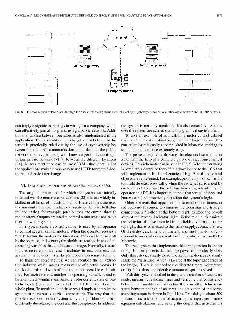
Another possible connection is presented in Fig. 8. In thisfigure, two factories belonging to the same company, and bothmanaged by Motronic, are joined together through an externalpublic network (for example, the Internet). The PCs on bothsides of the Internet link act as gateways between the token-busnetwork and TCP/IP, in a way that is totally transparent tocontrol LCNs. Of course, this solution can be extended to anynumber of plants. This way, it is possible to have a logicalequation stored in an LCN to depend on a digital input locatedin another factory, and communication of the present state ofthat input is carried by the external network. This approach
GARCÍA et al.: RECONFIGURABLE DISTRIBUTED NETWORK CONTROL SYSTEM FOR INDUSTRIAL PLANT AUTOMATION 1176
Fig. 8. Interconnection of two plants through the public Internet by using local PCs acting as gateways between local fiber-optic network and TCP/IP network.
can imply a significant savings in wiring for a company, whichcan effectively join all its plants using a public network. Addi-tionally, talking between operators is also implemented in theapplication. The possibility of attacking the plants from the In-ternet is practically ruled out by the use of cryptography be-tween the ends. All communication going through the publicnetwork is encrypted using well-known algorithms, creating avirtual private network (VPN) between the different locations[21]. As was mentioned earlier, use of XML throughout all ofthe applications makes it very easy to use HTTP for remote doc-ument and code interchange.
VI. INDUSTRIAL APPLICATIONS AND EXAMPLES OF USE
The original application for which the system was initiallyintended was the motor control cabinets [22] that are widely in-stalled in all kinds of industrial plants. These cabinets are usedto command all motors in a factory. Inputs for them are both dig-ital and analog, for example, push buttons and current throughmotor rotors. Outputs are used to control motor states and to actover the whole system.
In a typical case, a control cabinet is used by an operatorto control several similar motors. When the operator presses a“start” button, the motors are turned on. They can be turned offby the operator, or if security thresholds are reached in any of theoperating variables that could cause damage. Normally, controllogic is more elaborate, and it includes timers, counters, andseveral other devices that make plant operation semi-automatic.
To highlight some figures, we can mention the oil extrac-tion industry, which makes intensive use of electric motors. Inthis kind of plant, dozens of motors are connected to each cab-inet. For each motor, a number of operating variables need tobe monitored (winding temperature, rotor current, state of pro-tections, etc.), giving an overall of about 10 000 signals in thewhole plant. To monitor all of these would imply a complicatedsystem of numerous electrical connections. The way that thisproblem is solved in our system is by using a fiber-optic bus,drastically decreasing the cost and the complexity. In addition,
the system is not only monitored but also controlled. Actionsover the system are carried out with a graphical environment.
To give an example of application, a motor control cabinetusually implements a star–triangle start of large motors. Thisparticular logic is easily accomplished in Motronic, making itssetup and maintenance extremely easy.
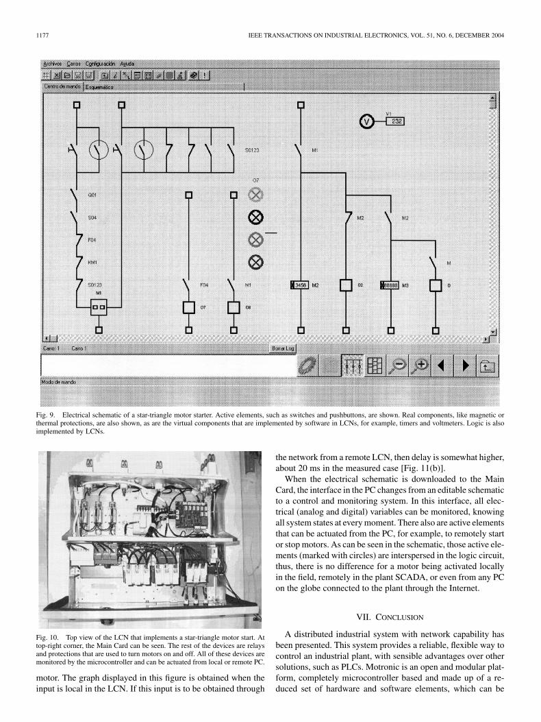
The process begins by drawing the electrical schematic ina PC with the help of a complete palette of electromechanicaldevices. This schematic can be seen in Fig. 9. When the drawingis complete, a compiled form of it is downloaded to the LCN thatwill implement it. In the schematic of Fig. 9, real and virtualobjects are represented. For example, pushbuttons shown at thetop right do exist physically, while the switches surrounded bycircles do not; they have the only function being activated by theoperator on a PC. It is important to note that virtual devices andbuttons can (and effectively do) affect the system’s logic.
Other elements that appear in this screenshot are: timers, inthe bottom-left corner, to commute between star and triangleconnection; a flip-flop at the bottom right, to store the on–offstate of the system; indicator lights, in the middle, that mimicthe behavior of those installed in the field; a voltmeter, at thetop right, that is connected to the mains supply; contactors, etc.Of these devices, timers, voltmeters, and flip-flops do not cor-respond to any real component, but are produced internally byMotronic.
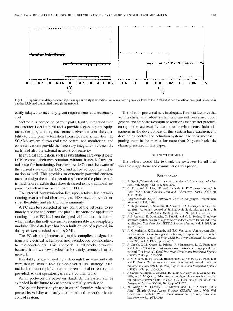
The real system that implements this configuration is shownin Fig. 10. Components that manage power can be clearly seen.Only those devices really exist. The rest of the devices exist onlyinside the Main Card (which is located at the top-right corner ofthe image). There is no need to use discrete timers, voltmeters,or flip-flops, thus, considerable amount of space is saved.
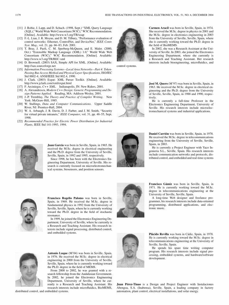
With this system installed in the plant, a number of tests weremade, measuring response times and verifying that consistencybetween all variables is always handled correctly. Delay mea-sured between change of an input and activation of the corre-sponding output is shown in Fig. 11(a). This delay is about 500
s, and it includes the time of acquiring the input, performingequation calculations, and setting the output that activates the
1177 IEEE TRANSACTIONS ON INDUSTRIAL ELECTRONICS, VOL. 51, NO. 6, DECEMBER 2004
Fig. 9. Electrical schematic of a star-triangle motor starter. Active elements, such as switches and pushbuttons, are shown. Real components, like magnetic orthermal protections, are also shown, as are the virtual components that are implemented by software in LCNs, for example, timers and voltmeters. Logic is alsoimplemented by LCNs.
Fig. 10. Top view of the LCN that implements a star-triangle motor start. Attop-right corner, the Main Card can be seen. The rest of the devices are relaysand protections that are used to turn motors on and off. All of these devices aremonitored by the microcontroller and can be actuated from local or remote PC.
motor. The graph displayed in this figure is obtained when theinput is local in the LCN. If this input is to be obtained through
the network from a remote LCN, then delay is somewhat higher,about 20 ms in the measured case [Fig. 11(b)].
When the electrical schematic is downloaded to the MainCard, the interface in the PC changes from an editable schematicto a control and monitoring system. In this interface, all elec-trical (analog and digital) variables can be monitored, knowingall system states at every moment. There also are active elementsthat can be actuated from the PC, for example, to remotely startor stop motors. As can be seen in the schematic, those active ele-ments (marked with circles) are interspersed in the logic circuit,thus, there is no difference for a motor being activated locallyin the field, remotely in the plant SCADA, or even from any PCon the globe connected to the plant through the Internet.
VII. CONCLUSION
A distributed industrial system with network capability hasbeen presented. This system provides a reliable, flexible way tocontrol an industrial plant, with sensible advantages over othersolutions, such as PLCs. Motronic is an open and modular plat-form, completely microcontroller based and made up of a re-duced set of hardware and software elements, which can be
GARCÍA et al.: RECONFIGURABLE DISTRIBUTED NETWORK CONTROL SYSTEM FOR INDUSTRIAL PLANT AUTOMATION 1178
Fig. 11. Experimental delay between input change and output activation. (a) When both signals are local to the LCN. (b) When the activation signal is located inanother LCN and transmitted through the network.
easily adapted to meet any given requirements at a reasonablecost.
Motronic is composed of four parts, tightly integrated withone another. Local control nodes provide access to plant equip-ment, the programming environment gives the user the capa-bility to build plant automation from electrical schematics, theSCADA system allows real-time control and monitoring, andcommunications provide the necessary integration between theparts, and also the external network connectivity.
In a typical application, such as substituting hard-wired logic,LCNs compute their own equations without the need of any cen-tral node for functioning. Furthermore, LCNs can be aware ofthe current state of other LCNs, and act based upon that infor-mation as well. This provides an extremely powerful environ-ment to design the actual operation scheme of the plant, whichis much more flexible than those designed using traditional ap-proaches such as hard-wired logic or PLCs.
The internal communication lies upon a token-bus networkrunning over a mixed fiber-optic and IrDA medium which en-sures flexibility and electric noise immunity.
A PC can be connected at any point of the network, to re-motely monitor and control the plant. The Motronic applicationrunning on the PC has been designed with a data orientation,which makes this software easily reconfigurable and completelymodular. The data layer has been built on top of a proved, in-dustry-chosen standard, such as XML.
The PC also implements a graphic compiler, designed totranslate electrical schematics into pseudocode downloadableto microcontrollers. This approach is extremely powerful,because it allows new devices to be easily connected to thenetwork.
Reliability is guaranteed by a thorough hardware and soft-ware design, with a no-single-point-of-failure strategy. Also,methods to react rapidly to certain events, local or remote, areprovided, so that operators can safely do their work.
As all protocols are based on standards, the system can beextended in the future to encompass virtually any device.
The system is presently in use in several factories, where it hasproved its validity as a truly distributed and network-orientedcontrol system.
The solution presented here is adequate for most factories thatwant a cheap and robust system and are not concerned aboutgeneric and standards-compliant solutions that are not practicalenough to be successfully used in real environments. Industrialpartners in the development of this system have experience indeveloping control and actuation systems, and their success inputting them in the market for more than 20 years backs theclaims presented in this paper.
ACKNOWLEDGMENT
The authors would like to thank the reviewers for all theirvaluable suggestions and comments on this paper.
REFERENCES
[1] A. Speck, “Reusable industrial control systems,” IEEE Trans. Ind. Elec-tron., vol. 50, pp. 412–418, June 2003.
[2] G. Frey and L. Litz, “Formal methods in PLC programming,” inProc. IEEE Conf. Systems, Man and Cybernetics (SMC), 2000, pp.2431–2436.
[3] Programmable Logic Controllers, Part 3: Languages, InternationalStandard 61131, 1993.
[4] N. Raghunandan, S. Sumithra, R. Anasuya, T. S. Natarajan, and G. Ran-garajan, “Automatic control of Stirling cycle liquid nitrogen plant,” inConf. Rec. IEEE-IAS Annu. Meeting, vol. 2, 1992, pp. 1721–1723.
[5] J. P. Agrawal, E. Bouktache, O. Farook, and C. R. Sekhar, “Hardwaresoftware system design of a generic embedded controller for industrialapplications,” in Conf. Rec. IEEE-IAS Annu. Meeting, vol. 3, 1995, pp.1887–1892.
[6] A. G. Malamos, K. Kalaitzakis, and N. C. Voulgaris, “A microcontroller-based system for monitoring and controlling the operation of an uninter-ruptible power supply,” in Proc. IEEE Int. Symp. Industrial Electronics(ISIE’95), vol. 2, 1995, pp. 610–615.
[7] J. García, J. M. Quero, R. Palomo, F. Manzanares, L. G. Franquelo,and J. Brey, “Distributed microprocessor controllers using optical fibernetwork,” in Proc. XV Conf. Design of Circuits and Integrated Systems(DCIS), 2000, pp. 557–560.
[8] J. M. Quero, R. Millán, M. Haidenthales, S. Fenoy, L. G. Franquelo,and R. Osuna, “Microprocessor board for industrial control of electricmotors,” in Proc. XIII Conf. Design of Circuits and Integrated Systems(DCIS), 1998, pp. 352–355.
[9] J. García, A. Luque, C. Aracil, F. R. Palomo, D. Carrión, F. Gámiz, P. Re-villa, and J. M. Quero, “Motronic: A configurable electronic controllerfor industrial power plants,” in Proc. XVIII Conf. Design of Circuits andIntegrated Systems (DCIS), 2003, pp. 673–676.
[10] M. Gudgin, M. Hardley, J.-J. Moreau, and H. F. Nielsen. (2003,June) “Simple Object Access Protocol (SOAP),” World Wide WebConsortium (W3C),” W3C Recommendation. [Online]. Available:http://www.w3.org/TR/soap
1179 IEEE TRANSACTIONS ON INDUSTRIAL ELECTRONICS, VOL. 51, NO. 6, DECEMBER 2004
[11] J. Robie, J. Lapp, and D. Schach. (1998, Sept.) “XML Query Language(XQL),” World Wide Web Consortium (W3C),” W3C Recommendation.[Online]. Available: http://www.w3.org/TR/soap
[12] F.-L. Lian, J. R. Moyne, and D. M. Tilbury, “Performance evaluation ofcontrol networks: Ethernet, ControlNet, and DeviceNet,” IEEE Contr.Syst. Mag., vol. 21, pp. 66–83, Feb. 2001.
[13] T. Bray, J. Paoli, C. M. Sperberg-McQueen, and E. Maler. (2000,Oct.) “Extensible Markup Language (XML) 1.0,” World Wide WebConsortium (W3C),” W3C Recommendation. [Online]. Available:http://www.w3.org/TR/REC-xml
[14] D. Brownell. (2003) SAX, Simple API for XML. [Online]. Available:http://sax.sourceforge.net
[15] Information Processing Systems—Local Area Networks—Part 4: Token-Passing Bus Access Method and Physical Layer Specifications, ISO/IECStd 8802-4; ANSI/IEEE Std 802.4, 1990.
[16] J. Clark. (2003) Expat: XML Parser Toolkit. [Online]. Available:http://www.jclark.com/xml/expat.html
[17] F. Arciniegas, C++ XML. Indianapolis, IN: New Riders, 2001.[18] A. Alexandrescu, Modern C++ Design: Generic Programming and De-
sign Patterns Applied. Reading, MA: Addison-Wesley, 2001.[19] J.-P. Tremblay, The Theory and Practice of Compiler Writing. New
York: McGraw-Hill, 1985.[20] W. Stallings, Data and Computer Communications. Upper Saddle
River, NJ: Prentice-Hall, 2004.[21] W. A. Arbaugh, J. R. Davin, D. J. Farber, and J. M. Smith, “Security
for virtual private intranets,” IEEE Computer, vol. 31, pp. 48–55, Sept.1998.
[22] Recommended Practice for Electric Power Distribution for IndustrialPlants, IEEE Std 141-1993, 1994.
Juan García was born in Seville, Spain, in 1965. Hereceived the M.Sc. degree in electrical engineeringand the Ph.D. degree from the University of Seville,Seville, Spain, in 1992 and 1995, respectively.
Since 1998, he has been with the Electronics En-gineering Department, University of Seville. His re-search is currently focused on microelectromechan-ical systems, biosensors, and position sensors.
Francisco Rogelio Palomo was born in Seville,Spain, in 1969. He received the M.Sc. degree infundamental physics in 1992 from the University ofSeville, Seville, Spain, where he is currently workingtoward the Ph.D. degree in the field of stochasticresonance.
In 1999, he joined the Electronics Engineering De-partment, University of Seville, where he currently isa Research and Teaching Assistant. His research in-terests include signal processing, distributed control,and embedded systems.
Antonio Luque (M’04) was born in Seville, Spain,in 1976. He received the M.Sc. degree in electricalengineering in 2000 from the University of Seville,Seville, Spain, where he is currently working towardthe Ph.D. degree in the field of MEMS.
From 2000 to 2002, he was granted with a re-search fellowship from the Andalusian Government.In 2002, he joined the Electronics EngineeringDepartment, University of Seville, where he cur-rently is a Research and Teaching Assistant. Hisresearch interests include microfluidics, BioMEMS,
distributed control, and embedded systems.
Carmen Aracil was born in Seville, Spain, in 1974.She received the M.Sc. degree in physics in 2001 andthe M.Sc. degree in electronics engineering in 2003from the University of Seville, Seville, Spain, whereshe is currently working toward the Ph.D. degree inthe field of BioMEMS.
In 2002, she was a Research Assistant at the Uni-versity of Seville. In 2003, she joined the ElectronicsEngineering Department, where she currently isa Research and Teaching Assistant. Her researchinterests include bioengineering, microfluidics, and
control systems.
José M. Quero (M’97) was born in Seville, Spain, in1963. He received the M.Sc. degree in electrical en-gineering and the Ph.D. degree from the Universityof Seville, Seville, Spain, in 1988 and 1990, respec-tively.
He is currently a full-time Professor in theElectronics Engineering Department, University ofSeville. His research interests include microelec-tromechanical systems and industrial applications.
Daniel Carrión was born in Seville, Spain, in 1978.He received the M.Sc. degree in telecommunicationsengineering from the University of Seville, Seville,Spain, in 2003.
He is currently a Project Engineer with Yaco In-genieria S.L., Seville, Spain. His research interestsinclude communication networks and protocols, dis-tributed control, and embedded and real-time systems
Francisco Gámiz was born in Seville, Spain, in1971. He is currently working toward the M.Sc.degree in telecommunications engineering at theUniversity of Seville, Seville, Spain.
A long-time Web designer and freelance pro-grammer, his research interests include data-orientedprogramming, distributed applications, and elec-tronic music.
Plácido Revilla was born in Cádiz, Spain, in 1978.He is currently working toward the M.Sc. degree intelecommunications engineering at the University ofSeville, Seville, Spain.
He spends his spare time writing computerprogram. His research interests include signal pro-cessing, embedded systems, and hardware/softwaredevelopment.
Juan Pérez-Tinao is a Design and Project Engineer with InstalacionesAbengoa, S.A. (Inabensa), Seville, Spain, a leading company in factoryautomation, plant control, electrical installations, and solar energy.

GARCÍA et al.: RECONFIGURABLE DISTRIBUTED NETWORK CONTROL SYSTEM FOR INDUSTRIAL PLANT AUTOMATION 1180
Manuel Moreno is a Design and Project Engineer with Instalaciones Abengoa,S.A. (Inabensa), Seville, Spain, a leading company in factory automation, plantcontrol, electrical installations, and solar energy.
Pedro Robles is the Logistics and Operations Director of InstalacionesAbengoa, S.A. (Inabensa), Seville, Spain, a leading company in factoryautomation, plant control, electrical installations, and solar energy.
Leopoldo G. Franquelo (M’85–SM’96) was born inMálaga, Spain. He received the Ing. Ind. and DoctorIngeniero Industrial (Ph.D.) degrees from the Univer-sity of Seville, Seville, Spain.
He is currently a full-time Professor in theElectronics Engineering Department, University ofSeville. His current research interests are intelligentcontrol of industrial drives and VLSI circuits forindustrial control.