2.1c p&id
6
Plant Operation by Dr. AA, 2008 Page 2.1c - ‹#› Piping and Instrumentation Piping and Instrumentation Diagram Diagram Dr. AA PiCS, UTM Piping and Instrumentation Diagram • Similarly to electrical schemas, the control industry (especially the chemical and process industry) describes its plants and their instrumentation by a • P&ID (pronounce P.N.I.D.) (Piping and Instrumentation Diagram), sometimes called P&WD (Piping and wiring diagrams) • The P&ID shows the flows in a plant (in the chemical or process industry) and the corresponding sensors or actors. • At the same time, the P&ID gives a name ("tag") to each sensor and actor, along with additional parameters. • This tag identifies a "point" not only on the screens and controllers, but also on the objects in the field.
Transcript of 2.1c p&id
Plant Operation by Dr. AA, 2008 Page 2.1c - ‹#›
Piping and InstrumentationPiping and InstrumentationDiagramDiagram
Dr. AAPiCS, UTM
Piping and Instrumentation Diagram• Similarly to electrical schemas, the control industry
(especially the chemical and process industry) describes itsplants and their instrumentation by a
• P&ID (pronounce P.N.I.D.) (Piping and InstrumentationDiagram), sometimes called P&WD (Piping and wiringdiagrams)
• The P&ID shows the flows in a plant (in the chemical orprocess industry) and the corresponding sensors or actors.
• At the same time, the P&ID gives a name ("tag") to eachsensor and actor, along with additional parameters.
• This tag identifies a "point" not only on the screens andcontrollers, but also on the objects in the field.

Plant Operation by Dr. AA, 2008 Page 2.1c - ‹#›
Piping & Instrumentation Diagram (P & I)• P & I should be included with
– All process equipment identified by equipment number– All pipes identified by a line number. Pipe size and material
of construction should be shown (material may include as apart of the identification number)
– All valves with an identification no. along with their type &size should be shown
– Ancillary fittings that are part of piping system such as inlinesight glasses, strainers and stream traps with anidentification no.
– Pumps identified by a suitable code no.– All control loops and instruments with identification
Plant Operation by Dr. AA, 2008 Page 2.1c - ‹#›
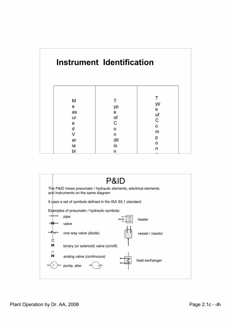
MMeeasasurureeddVVarariaiablblee
TTypypeeofofCCoonnditditioionnerer
TTypypeeofofCCoommppoonneentnt
FF==FlFlooww
RR==RRececorordderer
TT==TrTraansnsmimitttterer
LL==LLevevelel
II==InIndidicacatotorr
MM==MMoodifdifieierr
PP==PrPresessusurere
CC==CCoontntrorollellerr
EE==ElEleemmeentnt
QQ==QQuuaantintityty
AA==AlAlararmm
TT==TTeemmppereratatururee
Instrument Identification
P&IDThe P&ID mixes pneumatic / hydraulic elements, electrical elementsand instruments on the same diagram
It uses a set of symbols defined in the ISA S5.1 standard.
Examples of pneumatic / hydraulic symbols:pipe
valve
binary (or solenoid) valve (on/off)
350 kW heater
vessel / reactor
pump, also heat exchanger
analog valve (continuous)
one-way valve (diode)
Plant Operation by Dr. AA, 2008 Page 2.1c - ‹#›
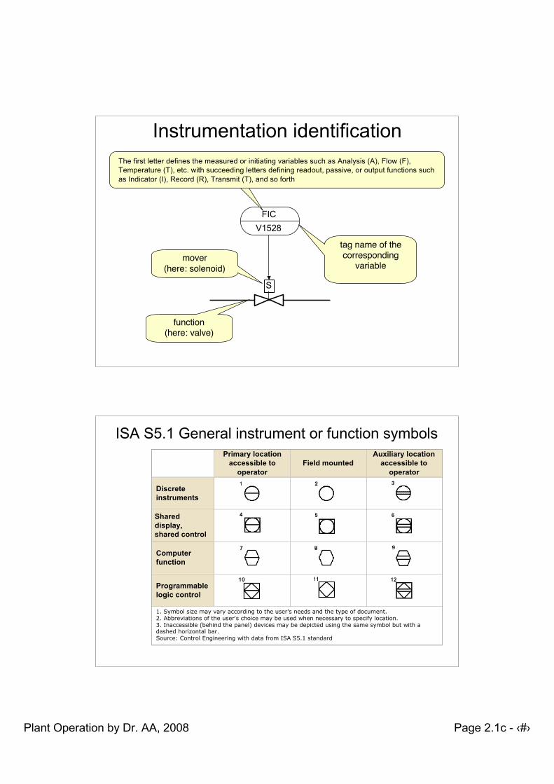
Instrumentation identification
V1528FIC
S
tag name of thecorresponding
variable
function(here: valve)
mover(here: solenoid)
The first letter defines the measured or initiating variables such as Analysis (A), Flow (F),Temperature (T), etc. with succeeding letters defining readout, passive, or output functions suchas Indicator (I), Record (R), Transmit (T), and so forth
ISA S5.1 General instrument or function symbolsPrimary location
accessible tooperator
Field mountedAuxiliary location
accessible tooperator
Discreteinstruments
Shareddisplay,shared control
Computerfunction
Programmablelogic control
1. Symbol size may vary according to the user's needs and the type of document.2. Abbreviations of the user's choice may be used when necessary to specify location.3. Inaccessible (behind the panel) devices may be depicted using the same symbol but with adashed horizontal bar.Source: Control Engineering with data from ISA S5.1 standard
Plant Operation by Dr. AA, 2008 Page 2.1c - ‹#›
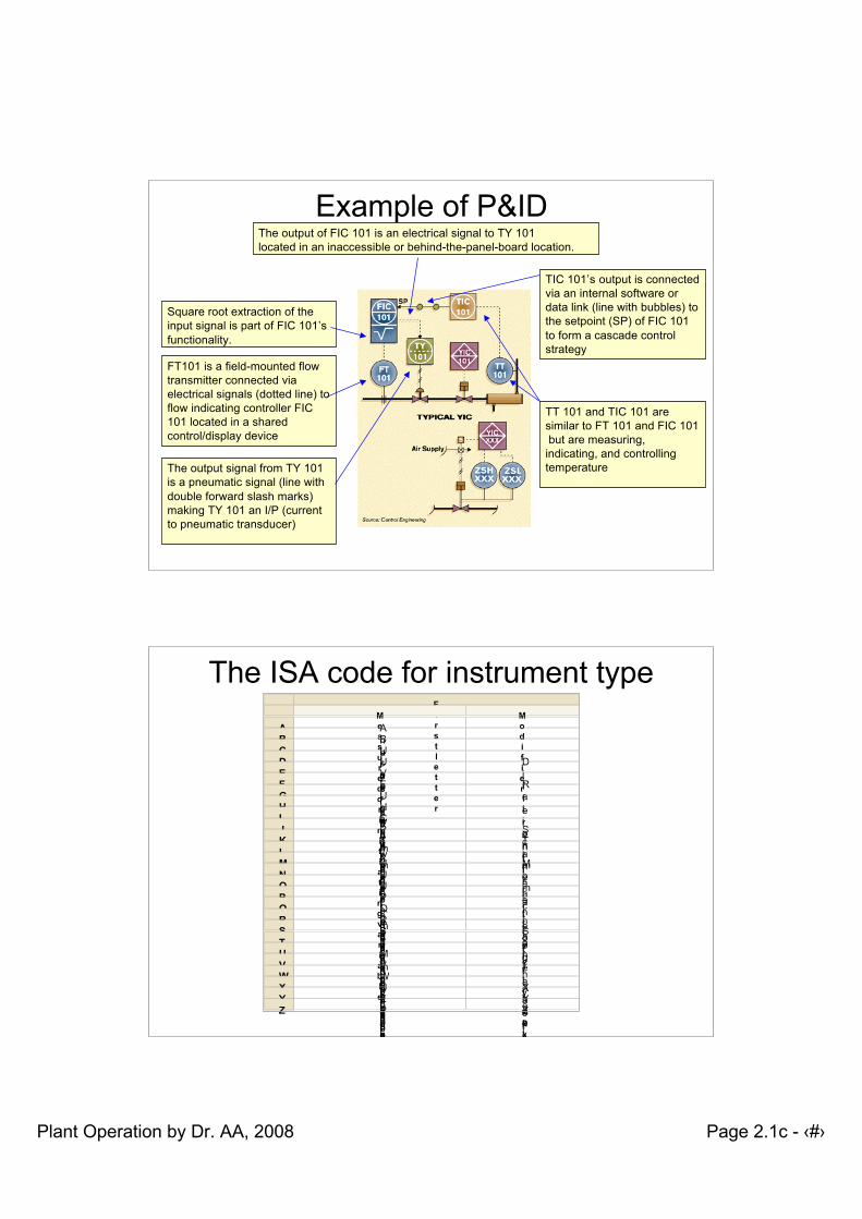
Example of P&ID
FT101 is a field-mounted flowtransmitter connected viaelectrical signals (dotted line) toflow indicating controller FIC101 located in a sharedcontrol/display device
Square root extraction of theinput signal is part of FIC 101’sfunctionality.
The output of FIC 101 is an electrical signal to TY 101located in an inaccessible or behind-the-panel-board location.
The output signal from TY 101is a pneumatic signal (line withdouble forward slash marks)making TY 101 an I/P (currentto pneumatic transducer)
TT 101 and TIC 101 aresimilar to FT 101 and FIC 101 but are measuring,indicating, and controllingtemperature
TIC 101’s output is connectedvia an internal software ordata link (line with bubbles) tothe setpoint (SP) of FIC 101to form a cascade controlstrategy
The ISA code for instrument typeFirstletter
Measuredorinitiatingvariable
Modifier
A Analysis
B Burner,combustion
C User'schoice
D User'schoice
Differential
E Voltage
F Flowrate
Ration(fraction)
G User'schoice
H Hand
I Current(electrical)
J Power
Scan
K Time,timeschedule
Timerateofchange
L Level
M User'schoice
Momentary
N User'schoice
O User'schoice
P Pressure,vacuum
Q Quantity
Integrate,totalizer
R Radiation
S Speed,frequency
Safety
T Temperature
U Multivariable
V Vibration,mechanicalanalysis
W Weight,force
X Unclassified
Xaxis
Y Event,state,orpresence
Yaxis
Z Position,dimension
Zaxis
Plant Operation by Dr. AA, 2008 Page 2.1c - ‹#›
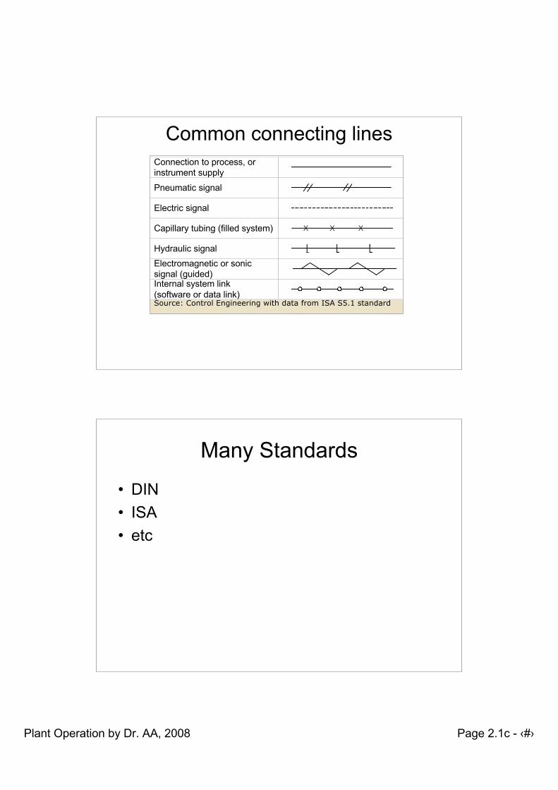
Common connecting linesConnection to process, orinstrument supply
Pneumatic signal
Electric signal
Capillary tubing (filled system)
Hydraulic signalElectromagnetic or sonicsignal (guided)Internal system link(software or data link)Source: Control Engineering with data from ISA S5.1 standard
Many Standards
• DIN• ISA• etc