2120 Multiplex - Fire Alarm Resourcesfirealarmresources.com/.../07/2120-System-Installation.pdf ·...
50
2120 Multiplex 4 System Installation 1 .--- ---. 0 1986 Simplex Time Recorder Co., Gardner, Mass. 01441-0001 U.S.A. MUX2-21-003 (575-557) Ed 10 86
Transcript of 2120 Multiplex - Fire Alarm Resourcesfirealarmresources.com/.../07/2120-System-Installation.pdf ·...
2120 Multiplex
4
System Installation
1 .--- ---.
0 1986 Simplex Time Recorder Co., Gardner, Mass. 01441-0001 U.S.A. MUX2-21-003 (575-557) Ed 10 86

TABLE OF CONTENTS
INTRODUCTION ...................................................................................................................................................... 3
Receiving/Inspecting Equipment ............................................................................................................ .:. ........ 3
Basic System Components ................................................................................................................................ 3
Removing Equipment from Cartons .................................................................................................................. 4
EQUIPMENT DOCUMENTATION ......................................................................................................................... 5
Basic Multiplex Equipment Order and Specification Sheet M-l 204 (Figure 4) ................................................ 7
21 20 CPU Equipment Order Form M-l 204 (Figure 5) ..................................................................................... 8
2120 Pre-Configured CPU, CPUSCC Multiplex Equipment Order Sheet OV-004 (Figure 8) ...................... 11
2120 Console Order and Specification Sheet M-1326 (Figure 9) .................................................................. 12
2120 Transponder Equipment Order and Specification Sheet M-l 203 (Figure 10) ...................................... 13
2120 Transponder Continuation Specification Sheet M-l 202 (Figure 1 1) ..................................................... 14
2120 Expanded Transponder Order and Specification Sheet M-1325 (Figure 12) ....................................... 15
2120 Expanded Transponder Functions Sheet M-1320 (Figure 13) .............................................................. 16
2120 Status Command Center Equipment Order Sheet M-1293 (Figure 14) ................................................ 17
2120 Status Command Center Continuation Specification Sheet M-l 294 (Figure 15) ................................. 18
2120 Control By Event Specification Sheet M-l 205-l (Figure 16) ................................................................ 19
210012120 Multiplex Life Alarm System - Call Report Form M-l 274 (Figure 17) ....................................... 20
2120 Initiating Wiring Diagrams M-2120 ......................................................................................................... 21
2120 ET Initiating Wiring Diagrams M-2120-ET ............................................................................................. 22
BACKBOXES ........................................................................................................................................................ 23
Limitations Imposed By 33AH Batteries ......................................................................................................... 24
Limitations Imposed By Transponder’s Power Supply ................................................................................... 24
SYSTEM WIRING ................................................................................................................................................ 25
System Interconnection Drawings .................................................................................................................. 25
Data and Power Line Interconnections ........................................................................................................... 26
Audio and Telephone Line Interconnections .................................................................................................. 26
BMUX Cabinet Drawing .................................................................................................................................. 39
SCC Cabinet Drawing ..................................................................................................................................... 40
Transponder Cabinet Drawings - Sample 1 ................................................................................................. 41
Transponder Cabinet Drawings - Sample 2 ................................................................................................. 42
Expanded Transponder Cabinet Drawings (Figure 38) .................................................................................. 55
INSTALLATION GUIDE ........................................................................................................................................ 56
Installation Precautions ................................................................................................................................... 56
Installation Guide ............................................................................................................................................ 57
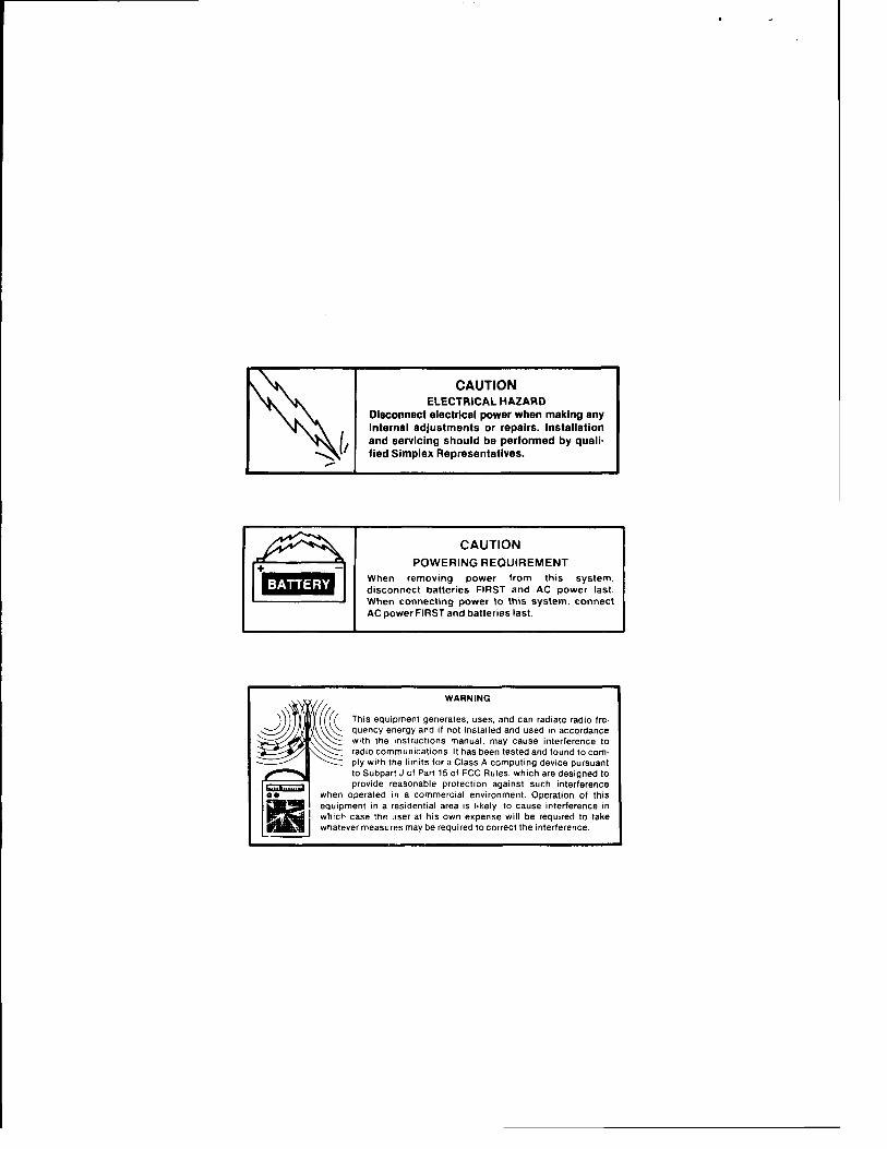
CAUTION ELECTRICAL HAZARD
Disconnect electrical power when making any internal adjustments or repairs. Installation and servicing should be performed by quali- fied Simplex Representatives.
CAUTION POWERING REQUIREMENT
When removing power from this system. disconnect batteries FIRST and AC power last. When connecting power lo this system. connect AC power FIRST and batteries last.
WARNING
This equipment generates, uses, and can radiate radio fre- quency energy and if not installed and used in accordance with the instructions manual, may cause interference to radio communications. It has been tested and found to com- ply with the limits for a Class A computing device pursuant to Subpart J of Part 15 of FCC Rules, which are designed to provide reasonable protection against such interference
when operated in a commercial environment. Operation of this equipment in a residential ares is likely to cause interference in which case the user at his own expense will be required to take whatever measures may be required to correct the interference.
INTRODUCTION
The 2120 Multiplex System consists of equipment that is designed to provide fire alarm, security, and energy management functions. As such, you must make sure that the system is installed in strict compliance with
.I national, state, and local codes.
The 2120 can be configured in many different ways, depending on customer requirements. Since the system is so versatile, installations will vary significantly from site to site. The purpose of this publication is to provide general installation considerations and instructions for the major components of the system. Specific installation drawings are provided with each system.
Receiving/Inspecting Equipment
When the equipment cartons are received, examine each for signs of damage that may have occurred during shipping.
If you detect damage, you must immediately place a claim with the carrier. If you know the extent of the damage, inform the carrier.
If possible, leave the equipment in the original containers until installation time.
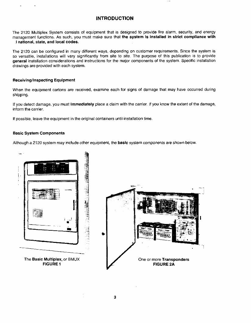
Basic System Components
Although a 2120 system may include other equipment, the basic system components are shown below.
The Basic Multiplex, or BMUX FIGURE 1
One or more Transponders FIGURE 2A
3
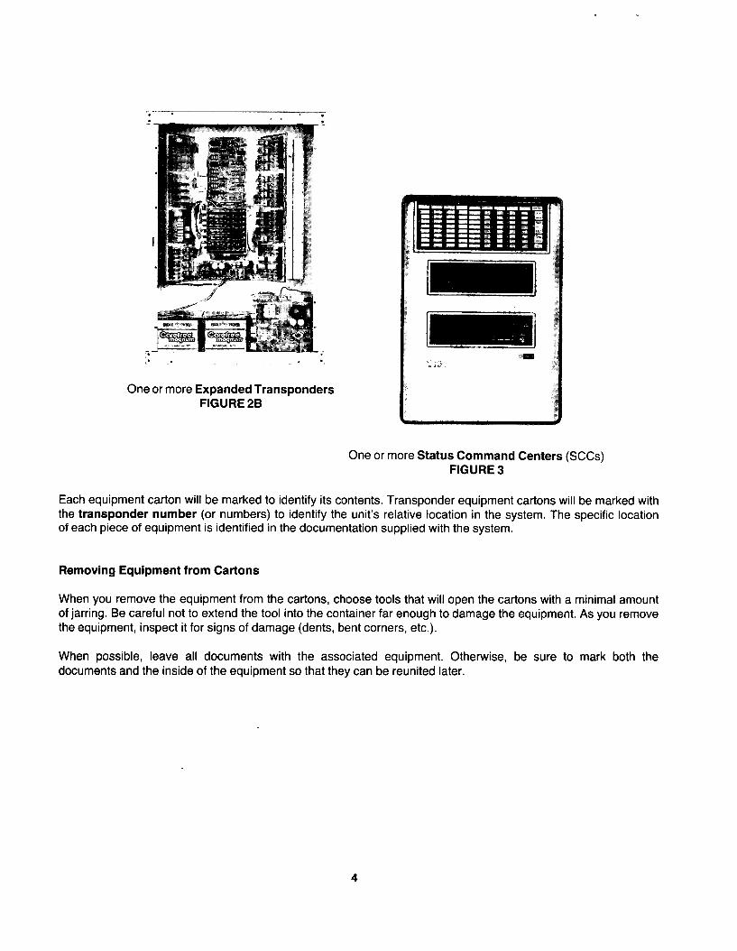
One or more Expanded Transponders FIGURE 28
One or more Status Command Centers (SCCs) FIGURE 3
Each equipment carton will be marked to identify its contents. Transponder equipment cartons will be marked with the transponder number (or numbers) to identify the unit’s relative location in the system. The specific location of each piece of equipment is identified in the documentation supplied with the system.
Removing Equipment from Cartons
When you remove the equipment from the cartons, choose tools that will open the cartons with a minimal amount of jarring. Be careful not to extend the tool into the container far enough to damage the equipment. As you remove the equipment, inspect it for signs of damage (dents, bent corners, etc.).
When possible, leave all documents with the associated equipment. Otherwise, be sure to mark both the documents and the inside of the equipment so that they can be reunited later.
4

EQUIPMENT DOCUMENTATION
Since each installation is unique, specific documentation is provided with every system. This documentation describes the equipment used in your system, and provides wiring and interconnection information. The documents usually supplied with each system are listed in Table A.
IMPORTANT!: Do not discard documents after the installation is complete. They are required for testing, inspection, and maintenance.
In addition to system-supplied documents, each installation will have specific site drawings. Site drawings show the location of all 2120 equipment required for an installation, as well as the amount and type of wire required. These site drawings may include either architectural drawings, riser diagrams, or both.
The site drawings and system-supplied documents provide sufficient information to completely install a 2120 system. We will discuss the system-supplied documents one-at-a-time.
Each specification sheet is divided into different areas. Some of the information on these sheets affects the way in which the system is installed; other information is used during inspection, maintenance, and repair of existing systems. For the purpose of this manual, the numbered areas on each sheet indicate information that affects system installation.
In addition to the numbered areas, the letters A, B, or C are written in the area adjacent to specific system features. These letters indicate the following:
A - This feature always affects external wiring. Refer to system wiring and interconnection drawings for details.
B - This feature may affect external wiring. Refer to system wiring and interconnection drawings for details.
C - This feature affects unit backbox installation. See the section of this manual dealing with backboxes for details.
5
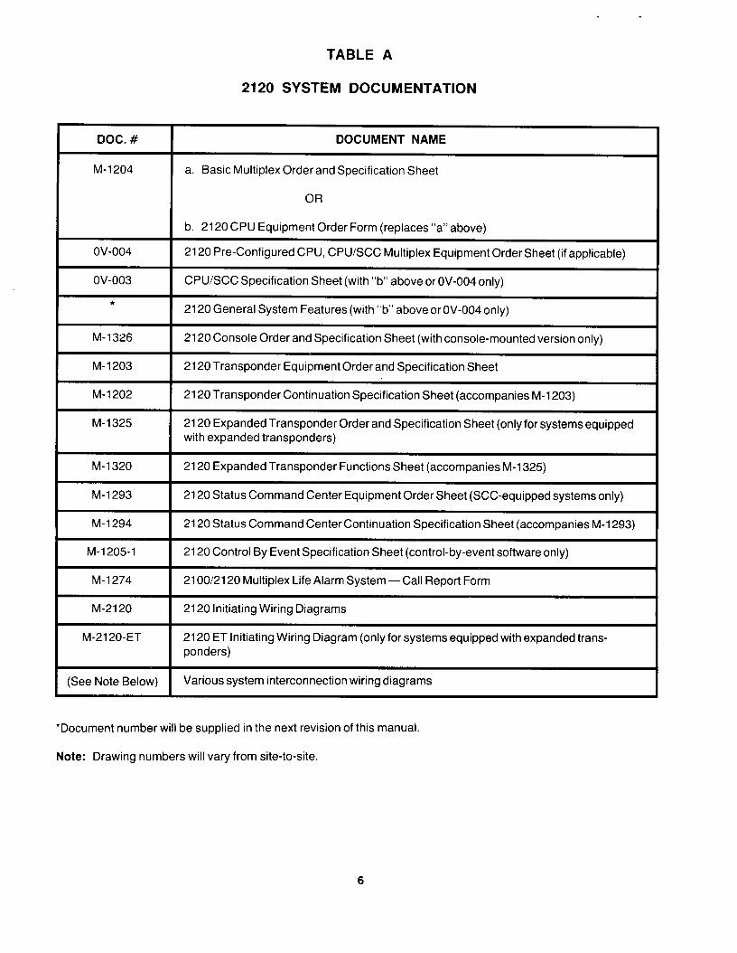
TABLE A
2120 SYSTEM DOCUMENTATION
DOC. # I DOCUMENT NAME
M-l 204 I
a. Basic Multiplex Order and Specification Sheet
I b. 2120 CPU Equipment Order Form (replaces “a” above)
I 2120 Pre-Configured CPU, CPUSCC Multiplex Equipment Order Sheet (if applicable)
I CPUSCC Specification Sheet (with “b” above or OV-004 only)
I 2120 General System Features (with “b” above or OV-004 only)
M-1326 I 2120 Console Order and Specification Sheet (with console-mounted version only)
M-l 203 I 2120 Transponder Equipment Order and Specification Sheet
M-l 202 I 2120 Transponder Continuation Specification Sheet (accompanies M-l 203)
M-l 325
I
2120 Expanded Transponder Order and Specification Sheet (only for systems equipped with expanded transponders) 7
M-1320 I 2120 Expanded Transponder Functions Sheet (accompanies M-l 325)
M-l 293 I
2120 Status Command Center Equipment Order Sheet (SCC-equipped systems only)
M-l 294 I 2120 Status Command Centercontinuation Specification Sheet (accompanies M-l 293)
M-l 205-l I 2120 Control By Event Specification Sheet (control-by-event software only)
M-l 274 I 210012120 Multiplex Life Alarm System-Call Report Form
M-21 20
M-2120-ET
2120 Initiating Wiring Diagrams
2120 ET Initiating Wiring Diagram (only for systems equipped with expanded trans- ponders)
(See Note Below) Various system interconnection wiring diagrams
*Document number will be supplied in the next revision of this manual.
Note: Drawing numbers will vary from site-to-site.
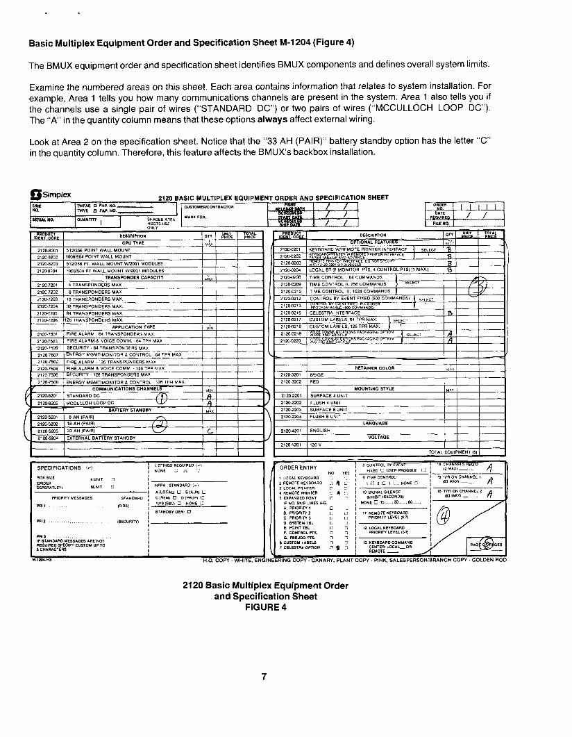
Basic Multiplex Equipment Order and Specification Sheet M-l 204 (Figure 4)
The BMUX equipment order and specification sheet identifies BMUX components and defines overall system limits.
Examine the numbered areas on this sheet. Each area contains information that relates to system installation. For example, Area 1 tells you how many communications channels are present in the system. Area 1 also tells you if the channels use a single pair of wires (“STANDARD DC”) or two pairs of wires (“MCCULLOCH LOOP DC”). The “A” in the quantity column means that these options always affect external wiring.
Look at Area 2 on the specification sheet. Notice that the “33 AH (PAIR)” battery standby option has the letter “C” in the quantity column. Therefore, this feature affects the BMUX’s backbox installation.
Simplex 2120 BASIC MULTIPLEX EQUIPMENT ORDER AND SPECIFICATION SHEET
ORDERENTRY
:OPY. PINK. SALESPERSON/BRANCH COPY. GOLDEN ROD
2120 Basic Multiplex Equipment Order and Specification Sheet
FIGURE 4
7
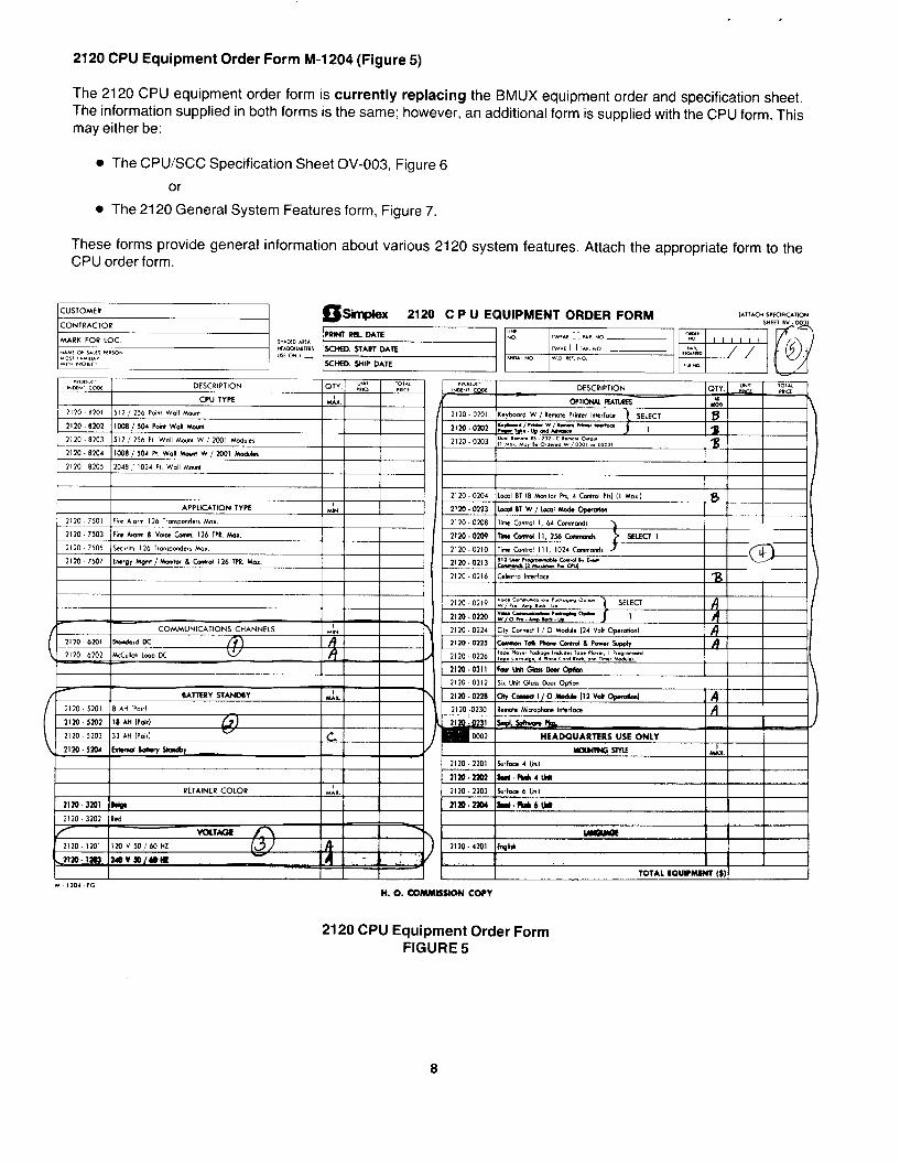
2120 CPU Equipment Order Form M-1204 (Figure 5)
The 2120 CPU equipment order form is currently replacing the BMUX equipment order and specification sheet. The information supplied in both forms is the same; however, an additional form is supplied with the CPU form. This may either be:
l The CPUSCC Specification Sheet OV-003, Figure 6
or
l The 2120 General System Features form, Figure 7.
These forms provide general information about various 2120 system features. Attach the appropriate form to the CPU order form.
COMMVNICATIONS CHANNELS
2120 6101 sm.3.d DC
RETAINER COLOR ix.
nm- 3101 I*ip.
2120 CPU Equipment Order Form FIGURE 5
8
CUSTOMER
a CONTRACTOR Simplex ~ El%sSO*i UOST . ..A W#T” “O,LCT X = INCLUDED FEATURE
.
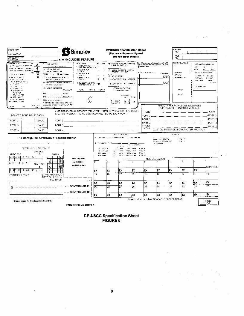
0 I
CPWSCC Spoclflcallon Shoot (For “I. with pncontlgund
and nowstock modelr)
REMOTE ACKNOWLEDGE MESSAGES (CUSTOM OR STANDARD MESSAGE)
REMOTE PORT BAUD RATES
LIST PERIPHERIAL DEVICES (PRINTERS, CRTS. KEYBOARDS TAPE DUMP. ETC) BY PRODUCT ID NUMBER CONNECTED TO EACH PORT
CBE _ _ _ - - - - - (CBE)
PORT 2-7 _ _ _ - - - -(PORT 2)
PORT 3- _ _ - - - - -(PORT 3
PORT4 _ _ _ _ _ _ - FRONT PANEL- _ _ _ - - - -<‘-,.--I
PORT 4
1 ADDRESS I ADDRESS SW POS SW POS
6 6 BAUD BAUD 1 1/214I6[161321 64 I 1 1/21416[161321 64 I ,I 11411 *Not r.qolr.d
1 CONTROLLER #l IllI I I IllI I I
1 I I 21 113
CONTROLLER #l vd21m-8211 SW POS SWPOS
1 1 .x.821? ordan
I 11214161161321 64 I 6
Ill11 I I I j CONTROLLER n2 STA
RATESELECTION -----
l 4600 BAUD
j CONTROLLER n2
4600 BAUD I I I I I I I I I I I
Ex ------------------CONTROLLERI / 29
IFX IFX IEX IEX IEX IEX IEX IEX
I
/ /j u( iW IEX lW 1EX 1U: /EX /EX (EX /EX
%l,d.d W.,l for “.adq”.n.n US. Only Insert Module ldentificallon numbers above
ENOINEERINQ COPY 1
CPU/SCC Specification Sheet FIGURE 6
9
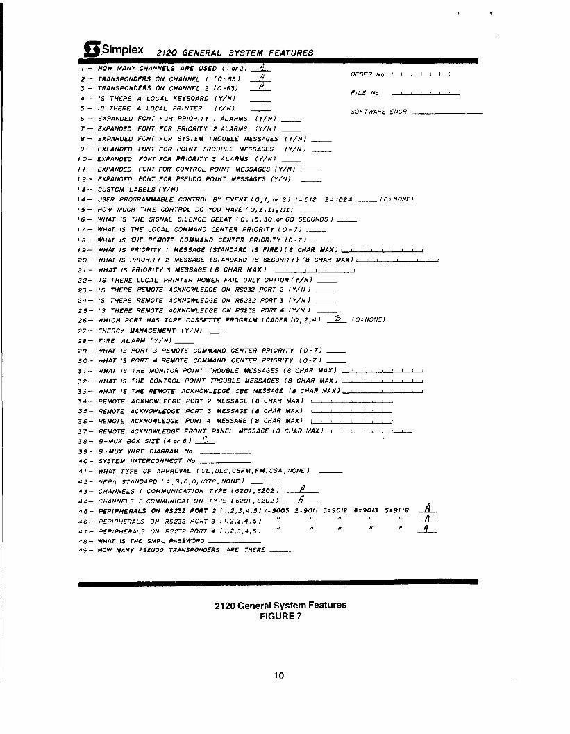
~simPlex 2120 GENERAL SYSTEM FEATURES
/ - .YOW MANY CHANNELS ARE USED I I or21 A
2 - TRANSPONDERS ON CHANNEL I (O-63 J A 3 - TRANSPONDERS ON CHANNEL 2 (O-63) m&m.
4 - IS THERE A LOCAL KEYBOARD IV/NJ -
5 - IS THERE A LO,CAL PRINTER (Y/NJ -
ORDER No ‘I
i/If No i 1 1 II II
S3FTWA4E ENGR. 6 - EXPANDED FONT FOR PRIORITY I ALARMS I Y/N) -
7 - MPANOEO FONT FOR PRICRITY 2 ALARMS (Y/N I -
8 - EXPANDED FJNT FOR SYSTEM TROUBLE MESSAGES (Y/NJ __
9 - EXPANOED FONT FOR POINT TROUBLE MESSAGES (Y/NJ __ I 0- EXPANDED FONT FOR PRIORITY 3 ALARMS (Y/NJ -
I i - EXPANDED FONT FOR CONTROL POINT MESSAGES f Y/NJ -
I 2- EXPANDED FONT FOR PSEUDO POINT MESSAGES (Y/NJ -
I3 -- CUSTOM LABELS (Y/N) -
I4 - USER PROGRAMMABLE CONTROL BY EVENT (0, I, or 2 J I = 512 2 = 1024 ___ (0; NONE)
15- HOW MUCH TIME CONTROL DO YOU HAVE I 0, I, II, IIIJ __
I6 - WHAT IS THE SIGNAL SILENCE DELAY IO, /5,30,or 60 SECONDS J -
I7- WHAT IS THE LOCAL COMMANO CENTER PRIORITY (O-7) __
I 8- WHAT IS WE REMOTE COMMAND CENTER PRIORITY (0 - 71 __
19- WHAT IS PRIORITY I MESSAGE (STANDARD IS FIRE) I8 CHAR MAXI L 1 t I t t I 1 I
20- WHAT IS PRIORITY 2 MESSAGE fSTANtJARCl IS SECURITY) fB CHAR MAX) I ! I ! I 1 I 2
2 I - WHAT /S PRIORITY 3 MESSAGE (8 CHAR MAX J 1 ! I I I t I
22- IS THERE LOCAL PRINTER POWER FAIL ONLY OPTION I Y/NJ - 23 - IS THERE REMOTE ACKNOWLEDGE ON RS232 PORT 2 (Y/N J -
2d- IS THERE REMOTE ACKNOWLEDGE ON RS232 PORT 3 (Y/N ) -
25 - IS THERE REMOTE ACKNOWLEDGE ON RS232 ?ORT 4 (Y/N ) __ 26- WHICH PORT HAS TAPE CASSETTE PROGRAM LOAOER (0,2,4J 2 ! 0 = Nm!El
27- ENERGY MANAGEMENT (Y/NJ ___
28- FIRE AL.aRM (Y/NJ __
29- WHAT IS PORT 3 REMOTE COMMAND CENTER PRIORITY (0 -7) -
30- WilLIT IS PORT 4 REMOTE COMMAND CENTER PRIORITY (O-7 1 ___
3 I - WHAT IS THE MONITOR POINT TROUBLE MESSAGES (8 CHAR MAX) I 1 a 1 1 1 ’ i
32- WHAT IS THE CONTROL POINT TsQGlJELE MESSAGES (8 CHAR MAX) I I I L I I
33- WHAT IS THE REMOTE ACKNOWLEDGE CBE HESSAGE (8 CHAR MAXI: : 1 I ,
34- REMOTE ACKNOWLEDGE PORT 2 YESSAGE f8 CHAR MAXJ I : 1 1 ’ 1 ! i
35- REMOTE ACKNOWLEDGE PORT 3 MESSAGE (8 CHAR MAXI L I ’ ’ ’ ’ I 3 6- REMOTE ACKNOWLEDGE PORT 4 MESSAGE ( 8 CHAR MAXI I 1 t I c c I I I
37 - REMOTE ACKNOWLEDGE FRONT PnNEL MESSAGE (8 CHAR MAXI I I : I I I 1 1 38- e-.uux aox s/zf (4 or 6 J C
3 9- 9 -MUX WlRE DIAGRAM No.
40- SYSTEM INTERCONNECT No.
4!- WH.IT TY.=E OF APPROVAL (L’L .ULC,CSFM.FM,CSA, NONE)
4 2- NF,=‘d STANDARD ( A, B, C,D, 1576, NONE ) ~
43- CHANNEiS I CO.MML’NICATION TYPE i 6201pS202 ) -A
DS- ChANNELS 2 COMMUNICATION TYPE (6201, 6202) vlt-
45- PfR/PHfRALS ON RS232 PORT 2 li,2,3,4,5J I=9005 Z-9011 3-9012 4=90/a 5=9118 -a-
46- PERIPHERALS DN RS232 PORT 3 ir,2,3,4,51 I‘ ” I’ ”
4 i- JE,?‘IPHERALS ON R3232 PORT 4 ( 1,2,3,4,5) ” ,I ,I II
48- WHAT IS THE SMPL PASSWORD 4C- HOW MANY PSEUOO TRANSPONDERS ARE THERE -_
2120 General System Features FIGURE 7
10
.
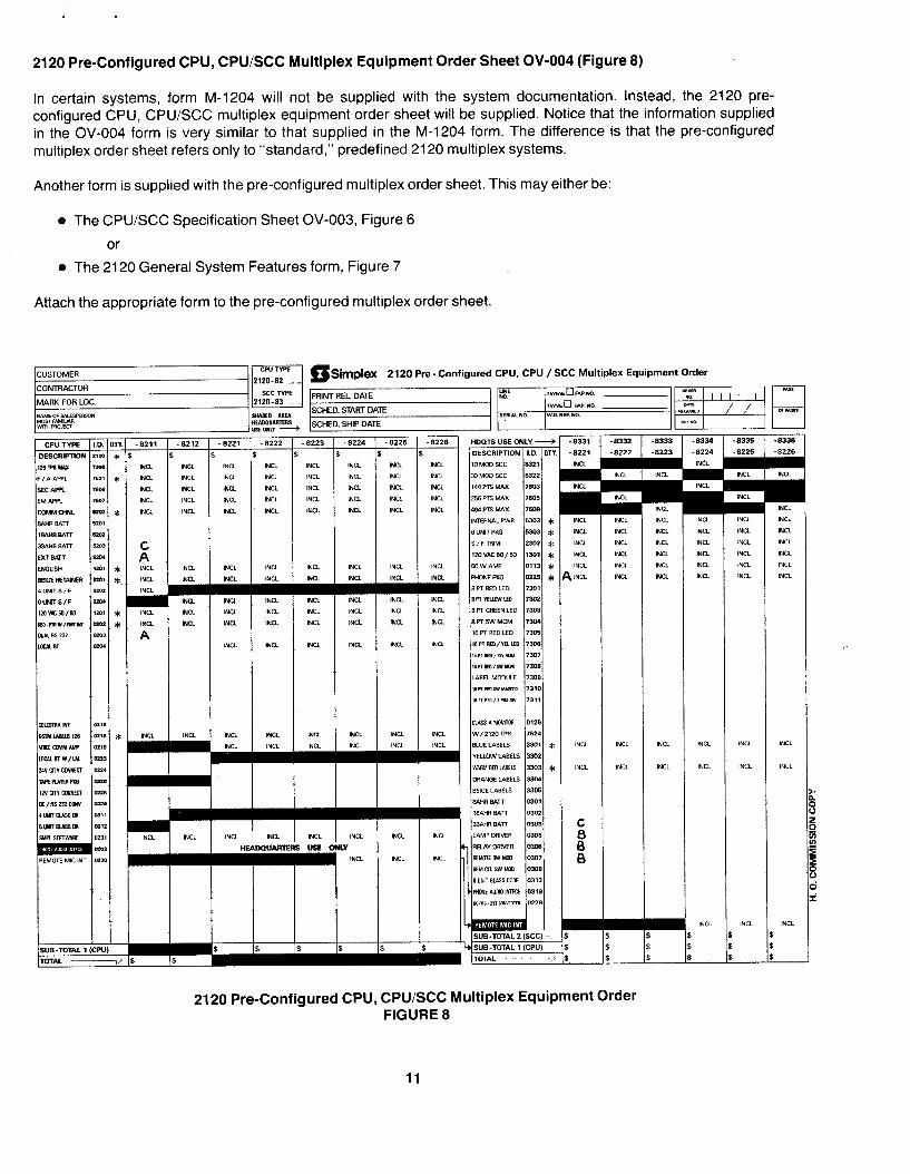
2120 Pre-Configured CPU, CPU/SCC Multiplex Equipment Order Sheet OV-004 (Figure 8)
In certain systems, form M-1204 will not be supplied with the system documentation. Instead, the 2120 pre- configured CPU, CPUSCC multiplex equipment order sheet will be supplied. Notice that the information supplied in the OV-004 form is very similar to that supplied in the M-1204 form. The difference is that the pre-configured multiplex order sheet refers only to “standard,” predefined 2120 multiplex systems.
Another form is supplied with the pre-configured multiplex order sheet. This may either be:
l The CPUSCC Specification Sheet OV-003, Figure 6
or
l The 2120 General System Features form, Figure 7
Attach the appropriate form to the pre-configured multiplex order sheet.
2120 Pre -Configured CPU, CPU / SCC Multiplex Equipment Order
5
II
II
3
5
II
5
I ID
INU
HE
ID
I
Am
: 5
I
II
5
D’
m 5 5
s
ID
ID
m f ,NCL INCL INU
,NCL
lNCL
Y INU
WJAKIE~USEC
/
--l-- e I
5 5
5
II 5
5
$
5 5
5
5
5
$
2120 Pre-Configured CPU, CPU/SCC Multiplex Equipment Order FIGURE 8
11
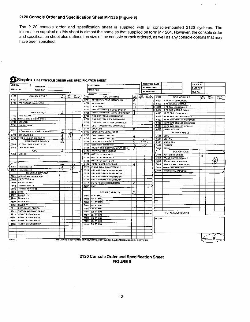
2120 Console Order and Specification Sheet M-l 326 (Figure 9)
The 2120 console order and specification sheet is supplied with all console-mounted 2120 systems. The information supplied on this sheet is almost the same as that supplied on form M-l 204. However, the console order and specification sheet also defines the size of the console or rack ordered, as well as any console options that may have been specified.
hpkX 2120 CONSOLE ORDER AND SPECIFICATION SHEET - LlWE No
2120 Console Order and Specification Sheet FIGURE 9
12
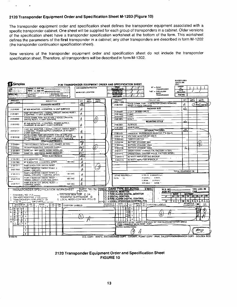
2120 Transponder Equipment Order and Specification Sheet M-1203 (Figure 10)
The transponder equipment order and specification sheet defines the transponder equipment associated with a specific transponder cabinet. One sheet will be supplied for each group of transponders in a cabinet. Older versions of the specification sheet have a transponder specification worksheet at the bottom of the form. This worksheet defines the parameters of the first transponder in a cabinet; any other transponders are described in form M-1202 (the transponder continuation specification sheet).
New versions of the transponder equipment order and specification sheet do not include the transponder specification sheet. Therefore, all transponders will be described in form M-l 202.
iSimplex HWTSUSE
2120 TRANSPONDER EQUIPMENT ORDER AND SPECIFICATION SHEET ONL” , 1 C”STOMEFvCONTR*CTOR wm 1 aK* c.*c tiam
BT WI8 MONlTOR 4 CONTROL ‘/I “NIT SURFACE .: SMOKE RESET; IA I
2120-9332 YOICE COMM FAST WE ZONES; 3 VOICE CIRCUITS; SMOKE RESET. % “NIT SURFACE A
2120-9100 ST W,S MON,TOR .4 CONTROL; POWER SUPPLY; CHARGER; 33 AH BAIT. 2 “NIT SURFACE A FAST wn MlJN,TOR; 1 CIRCUIT- SMOKE RESET
2120.9101 2 CONTROL: POWER SUI
OPERA!I”N.aL CHARGE (WA. FACTORY INTER.,
OPERATlONAL CHARGE (VOICE. FACTORY INTER) 50 WATT AMPLIFIER WI0 BACKUP 50 WATT AMPLlFlER WlBACKUP 2120-7001 ST 8 MONITOR ONLY la I I 21200114
2120.7003 1 IDPDT) I2O”AC A ,
ST 8 MONITOR 4 CONTROL
TRANSPONDER SPECIFICATION WORKSHEET
TRANSIENT SUPPRESSOR
N ki.0. COPY -WHITE, ENGINEERI~ARY, PLANT COPY. PINK, SALESPERSONlBRANCH COPY -GOLDEN F
2120 Transponder Equipment Order and Specification Sheet FIGURE 10
13
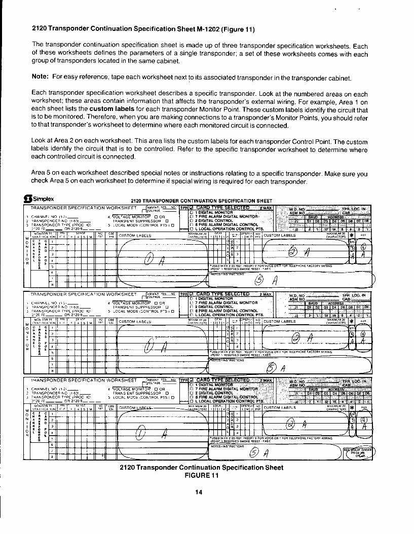
2120 Transponder Continuation Specification Sheet M-1202 (Figure 11)
The transponder continuation specification sheet is made up of three transponder specification worksheets. Each of these worksheets defines the parameters of a single transponder; a set of these worksheets comes with each group of transponders located in the same cabinet.
Note: For easy reference, tape each worksheet next to its associated transponder in the transponder cabinet.
Each transponder specification worksheet describes a specific transponder. Look at the numbered areas on each worksheet: these areas contain information that affects the transponder’s external wiring. For example, Area 1 on each sheet lists the custom labels for each transponder Monitor Point. These custom labels identify the circuit that is to be monitored. Therefore, when you are making connections to a transponder’s Monitor Points, you should refer to that transponder’s worksheet to determine where each monitored circuit is connected.
Look at Area 2 on each worksheet. This area lists the custom labels for each transponder Control Point. The custom labels identify the circuit that is to be controlled. Refer to the specific transponder worksheet to determine where each controlled circuit is connected.
Area 5 on each worksheet described special notes or instructions relating to a specific transponder. Make sure you check Area 5 on each worksheet to determine if special wiring is required for each transponder.
B Simplex 2120 TRANSPONDER CONTINUATIC
TRANSPONDER SPECIFICATION WORKSHEET CARD’
IN SPECIFICATION SHEET
1 CHANNEL NO (1 21- a 7 fw ALARM DIGITAL 7 TRANSPONDER NO 1,.63,- TRANSIENT SUPPRESSOR 0 0 2 DIGITAL CONTROL
TRANSPONDER TYPE ,PROD IDI 5 LOCAL MODE [CONTROL PTS, 0 CY E FIRE ALARM DIGiTAL CONTftOt
TRANSPONDER SPECIFICATION WORKSHEET
CHANNEL NO II 21- TRANSPONDER NO ,I 631- TRANSIENT SUPPRESSOR 0 TRANSPONDER TYPE ,PROD IDI 5 LOCAL MODE ,CONTROL PTS / 0 212070-m OR2120-9---
MON,lOR Pi PRI SENSE CBE lDENllFICATION 0 31 F , A , 5 , H PNRq “IN CUSTOM LABELS ^ - _I /I
cl 7 FIRE ALARM DIGITAL MONITOR Cl 2 MGITAL CONTROL 0 8 FIRE ALAAM DIBITAL CONTROL
TRANSPONDER SPECIFICATION WORKSHEET
2120 Transponder Continuation Specification Sheet FIGURE 11
14
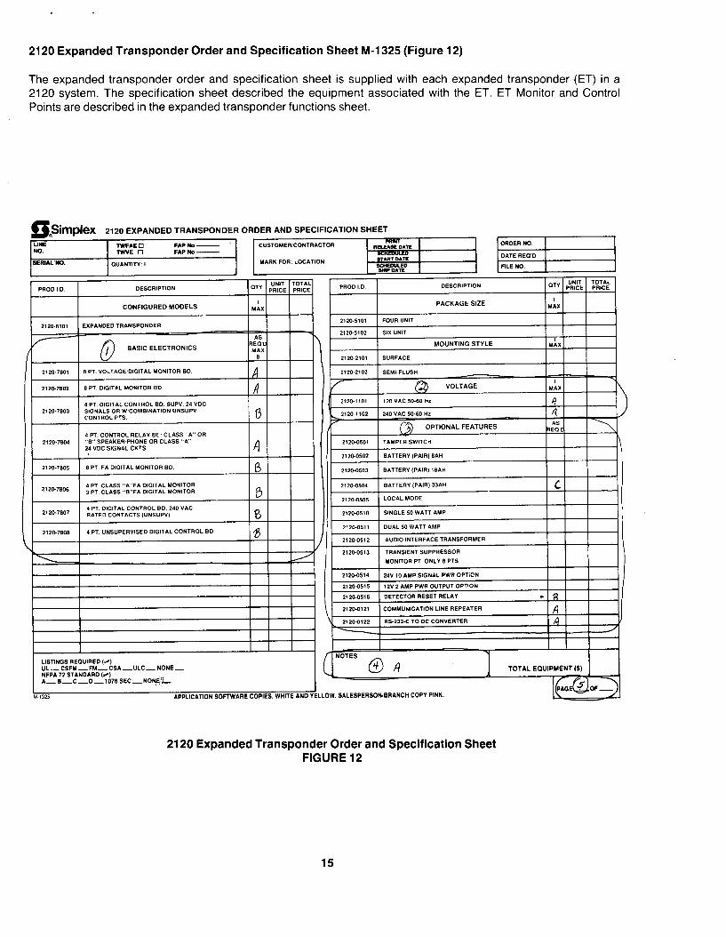
2120 Expanded Transponder Order and Specification Sheet M-l 325 (Figure 12)
The expanded transponder order and specification sheet is supplied with each expanded transponder (ET) in a 2120 system. The specification sheet described the equipment associated with the ET. ET Monitor and Control Points are described in the expanded transponder functions sheet.
0: BSimplex 2120 EXPANDED TRANSPONDER ORDER AND ~PECIPICAT~~N SHEET
LINE TWFAE 0 FAPND- i C”S.TCMERICONTRACTCR PWNT NC. R- OATi
TWVE 0 FAPNO- 6ERbAL NC. START n*TE OVANTITY: I MARK FOR: LOCATKJN scEuu.w YIPDAlZ
PACKAGE SIZE .hx
2120-6101 FOUR “NIT
2120-0614 24Y 10 AMP SIGNAL PWR OPTICN
2120-0615 12” 2 AMP PWR OUTPUT OPTION
21204616 DETECTOR RESET RELAY -
I I I I LSTINOS REOUIREC (4 UL-CSFM-FM-CSA-ULC-NONE- NFPA 72 STANDARD Ii4 A_B_C_D-1076SEC-N0~~~
M 1321 APPLICATION SOFTWARE COPIES. WHITE AND YELLOW. SALESPERSONIERANCli COPY PINK.
TOTAL EQUIPMENT(S)
2120 Expanded Transponder Order and Specification Sheet FIGURE 12
15
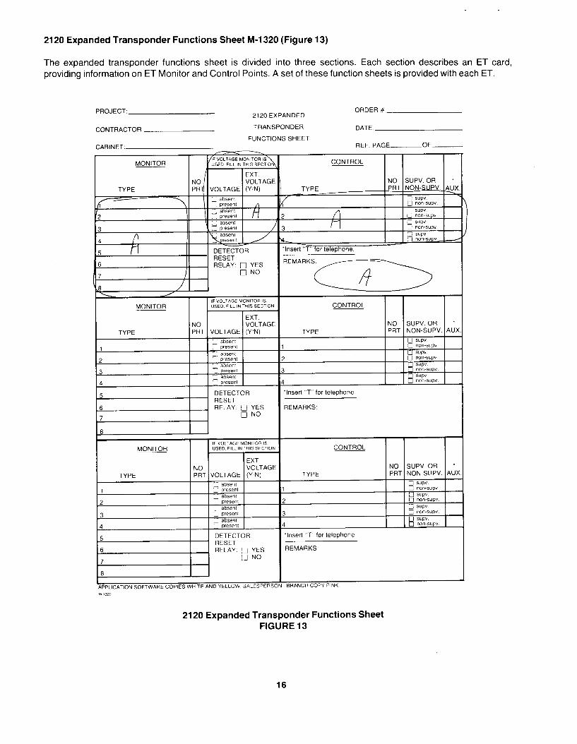
2120 Expanded Transponder Functions Sheet M-l 320 (Figure 13)
The expanded transponder functions sheet is divided into three sections. Each section describes an ET card, providing information on ET Monitor and Control Points. A set of these function sheets is provided with each ET.
PROJECT: ORDER # 2120 EXPANDED
CONTRACTOR TRANSPONDER DATE.
FUNCTIONS SHEET REF. PAGE OF------- CABINET:
MONITOR CONTROL I
EXT VOLTAGE
-1 RELAY. i ‘N’o
I IF VOLTAGE MONITOR IS
MONITOR USED FILL IN THIS SECTION
1 EXT
TYPE NO VOLTAGE PRT VOLTAGE (Y’N)
atw?nt
6 I RELAY q YES n NO
IF VOLTAGE MCWIITCR IS MONITOR USED FILL IN THIS SECTICN
TYPE I ~I%TIVOLTAGE I $iAGE
5 I RELAY g YES 7 0 NO
PPLICATION SOFTWARE COPIES WHITE AND YELLOW SALESPERSO
TYPE
,
I
I
‘Insert “T” for telephone
NO SUPV. OR * PRT NON-SUPV. AUX.
0 SUPV q non-sup” 0 SUPV q “on-sup” 0 SUPV q non-sup” 0 SUPV q “on-sup”
REMARKS.
CONTROL
TYPE NO SUPV. OR * PRT NON-SllPV AUX.
a BRANCH COPY PINK
2120 Expanded Transponder Functions Sheet FIGURE 13
16
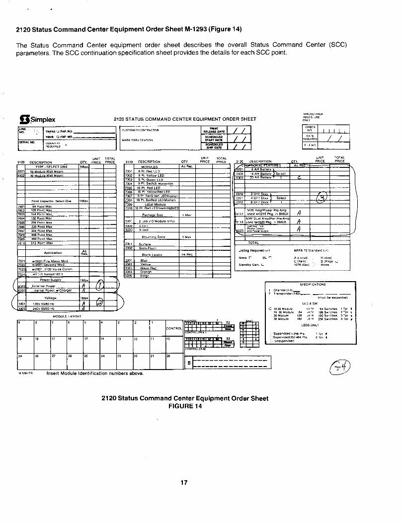
2120 Status Command Center Equipment Order Sheet M-l 293 (Figure 14)
The Status Command Center equipment order sheet describes the overall Status Command Center (SCC) parameters. The SCC continuation specification sheet provides the details for each SCC point.
Fimplex SHADEDARE&
2120 STATUS COMMAND CENTER EQUIPMENT ORDER SHEET HOOTS “SE ONLY
UNIT TOTAL “NIT TOTAL
29 28 27 26 25 24 23 22 21 m-
----------------
M.1293 PO Insert Module Identification numbers above.
2120 Status Command Center Equipment Order Sheet FIGURE 14
17
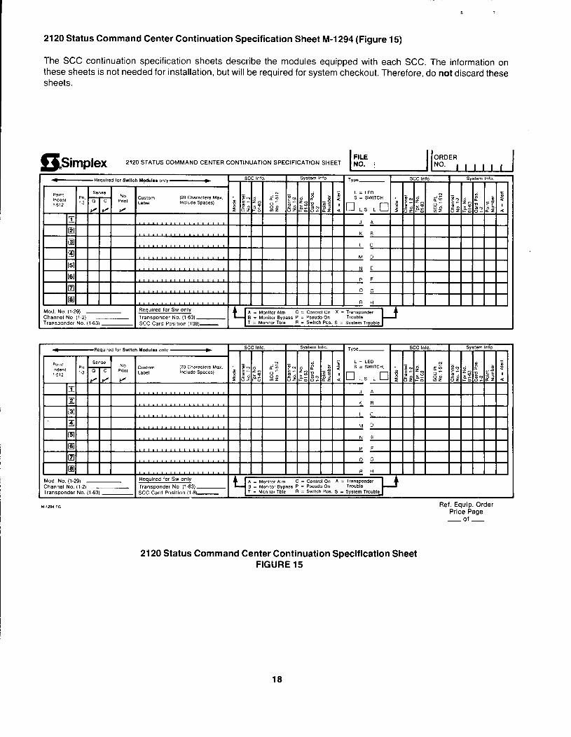
2120 Status Command Center Continuation Specification Sheet M-1294 (Figure 15)
The SCC continuation specification sheets describe the modules equipped with each SCC. The information on these sheets is not needed for installation, but will be required for system checkout. Therefore, do not discard these sheets.
2120 STATUS COMMAND CENTER CONTINUATION SPECIFICATION SHEET
Channel NO (1.2) ___ Transponder No. (l-63)- 6 = Monitor Bypass P = Pseudo on Transponder No (l-63) SCC Card POSI,IO” IlOB)- T = R = =
I I I I I I I I I I I I I I R H I I I I I I I I I Mod NO. (129) Required for SW only A = Monitor Alnl c = Control on x = TranSpOnder Channel NO. (1.2) ___ Transponder No. (163)- 6 = Momfor Bypass P = Pseudo on Transponder NO. (1.63) SCC Card Positron (1.8: T = R = Switch POS. 6 = System Trouble
Ref. Equip. Order Price Page
- of -
2120 Status Command Center Continuation Specification Sheet FIGURE 15
18
. ,
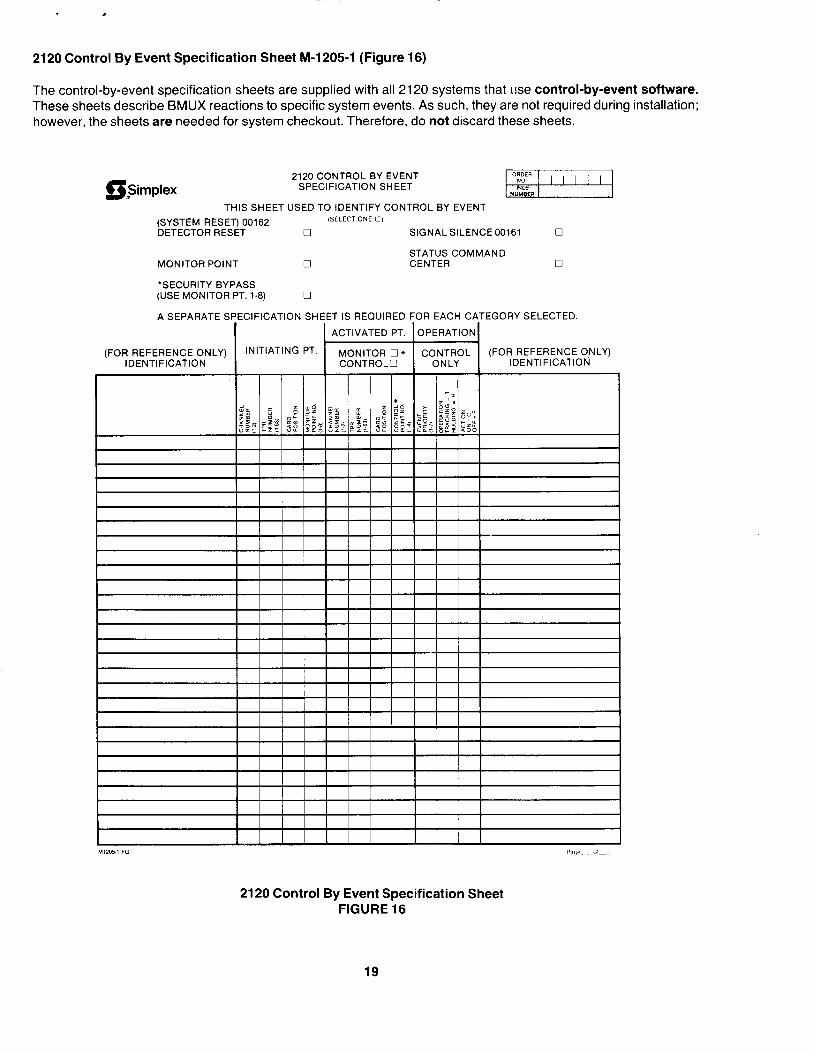
2120 Control By Event Specification Sheet M-l 205-l (Figure 16)
The control-by-event specification sheets are supplied with all 2120 systems that l!se control-by-event software. These sheets describe BMUX reactions to specific system events. As such, they are not required during installation; however, the sheets are needed for system checkout. Therefore, do not discard these sheets.
2120 CONTROL BY EVENT SPECIFICATION SHEET
THIS SHEET USED TO IDENTIFY CONTROL BY EVENT
(SYSTEM RESET) 00162 ,SEl.ECT ONE 0)
DETECTOR RESET 0 SIGNAL SILENCE 00161 0
STATUS COMMAND MONITOR POINT 0 CENTER 0
‘SECURITY BYPASS (USE MONITOR PT. 1-8) 0
A SEPARATE S
(FOR REFERENCE ONLY) IDENTIFICATION
33FICATION SHEET IS REQUIRED FOR EACH CATEGORY SELECTED.
2120 Control By Event Specification Sheet FIGURE 16
19
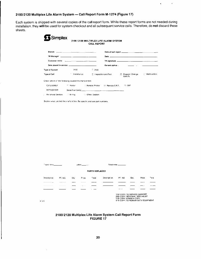
2100/2120 Multiplex Life Alarm System -Call Report Form M-1274 (Figure 17)
Each system is shipped with several copies of the call report form. While these report forms are not needed during installation, they will be used for system checkout and all subsequent service calls. Therefore, do not discard these sheets.
Simplex 2100 I2120 MULTIPLEX LIFE ALARM SYSTEM
CALL REPORT
Branch Date 01 last report
TR Manager Date
Customer name TR signatue
Date placed in service current status
Type of System 2100 7 2120
Type 01 Call lnstallatlon C Inspection and Test 0 Program Change Specify
Check which of the followlng caused the malfunction:
C.P.U./BMUX ;’ Pllnter C Remote Printer 0 Remote C.R.T. 0 CRT
BTIFABTITPR Serial Number(s)
Peripheral Dewces :: w,r,ng 0 Other, Explain
0 Malfunction
Explain what caused the malfunction. Be specific and use part numbers
Travel time Labor- Total tome -
PARTS REPLACED
Description PT NO city. PrlCe Total Description PT. NO. CJty. Price Tot.4
--~~ ----
__---
----
TOP COPY: TO SERVICE SUPPORT 2ND COPY: REGIONAL SPECIALIST 3RD COPY: BRANCH COPY 4TH COPY: TO REMAIN WITH EQUIPMENT
2100/2120 Multiplex Life Alarm System Call Report Form FIGURE 17
20
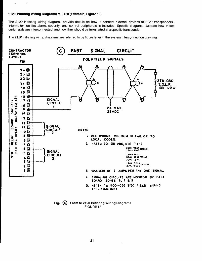
2120 Initiating Wiring Diagrams M-21 20 (Example, Figure 18)
The 2120 initiating wiring diagrams provide details on how to connect external devices to 2120 transponders. Information on fire alarm, security, and control peripherals is included. Specific diagrams illustrate how these peripherals are interconnected, and how they should be terminated at a specific transponder.
The 2120 initiating wiring diagrams are referred to by figure letter in the system interconnection drawings.
CONTRACTOR TERMINAL LAYOUT
TEII
n C FABT SIGNAL c I RCUIT
3?8-030 E.O.L.R. IOK l/2W
28VDC
-1 SIGN AL
“RzculT
-J
NOTES:
1 ALL WIRING MlHlMUM 14 AWC OR TO LOCAL CODES.
2. RATED 20 -28 VDC, STR TYPE
2901- 9320 2901-9321 SELLS 2901- 9322
2.902-9203 CH,MES 2902 - 9204
3. MAXIMUM Of 2 AMPS PER ANY ONE SIGNAL.
4. SIGNALING CIRCUITS ARE MONnOR RV FABT BOAR0 ZONES 6, 7 8 8
5. REFER 70 900-036 2120 FIELD WIRING SPECIPICATIONS.
Fig. @ From M-21 20 Initiating Wiring Diagrams FIGURE 18
21
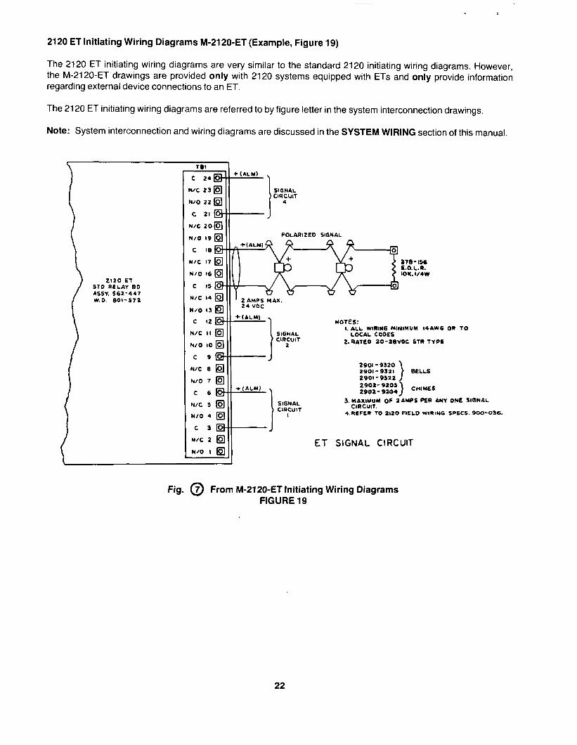
2120 ET Initiating Wiring Diagrams M-2120~ET (Example, Figure 19)
The 2120 ET initiating wiring diagrams are very similar to the standard 2120 initiating wiring diagrams. However, the M-2120-ET drawings are provided only with 2120 systems equipped with ETs and only provide information regarding external device connections to an ET.
The 2120 ET initiating wiring diagrams are referred to by figure letter in the system interconnection drawings.
Note: System interconnection and wiring diagrams are discussed in the SYSTEM WIRING section of this manual.
2120 e-r ST0 RELAY 80 ASSY. 562-447 W.O. SOi-572
I
SIGNAL CIRCUIT
4
Y/O IV
c I8
WC 17
N/O I6
C IS
N/C I4
N/O 13
c I2
pa. __ .--- -.-.._.
“” NOTES:
t
-.-_. 1. ALL WIRING MINIMUM I4AWG
SIGNIL LOCAL CODES CIRCUIT
2 Z.RAlfiO ZO-28VOC STR fYP6
J 29Ol- 9320 2901-9321 \ BELLS
OR TO
2901-9322 J 2902- 9203 2902- 9204
SIGNAL CIl?CUIT
I 4.FIEFER TO 2120 PlELO WIRING SPECS. 900-036.
ET SIGNAL CIRCUIT
Fig. @ From M-2120-ET Initiating Wiring Diagrams FIGURE 19
22
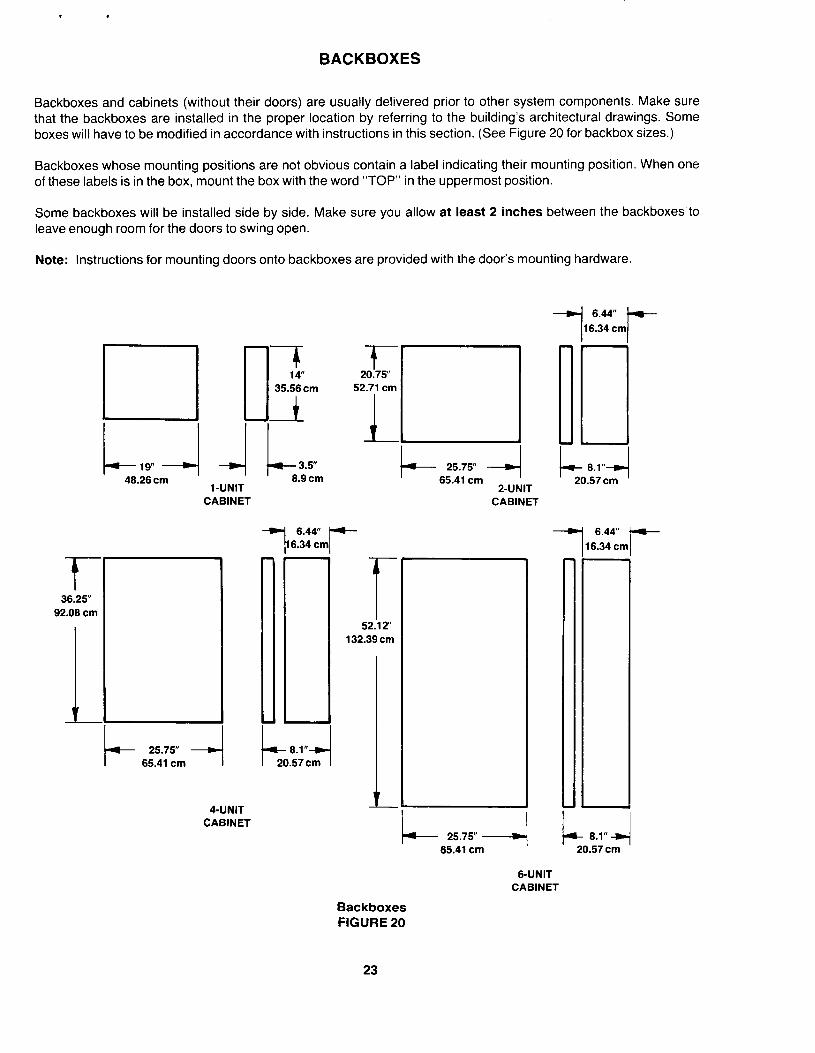
BACKBOXES
Backboxes and cabinets (without their doors) are usually delivered prior to other system components. Make sure that the backboxes are installed in the proper location by referring to the building’s architectural drawings. Some boxes will have to be modified in accordance with instructions in this section. (See Figure 20 for backbox sizes.)
Backboxes whose mounting positions are not obvious contain a label indicating their mounting position. When one of these labels is in the box, mount the box with the word “TOP” in the uppermost position.
Some backboxes will be installed side by side. Make sure you allow at least 2 inches between the backboxes to leave enough room for the doors to swing open.
Note: Instructions for mounting doors onto backboxes are provided with the door’s mounting hardware.
48.26cm ’ I I
i-UNIT 8.9 cm
CABINET
t 38.25”
92.08 cm
4-UNIT CABINET
6.44” 6.34 cm r-
-r 20.75”
52.71 cm
L El
L 25.75” -+/ I 65.41 cm I
’ 20.57cm ’ 2-UNIT
CABINET
B-UNIT CABINET
Backboxes FIGURE 20
23
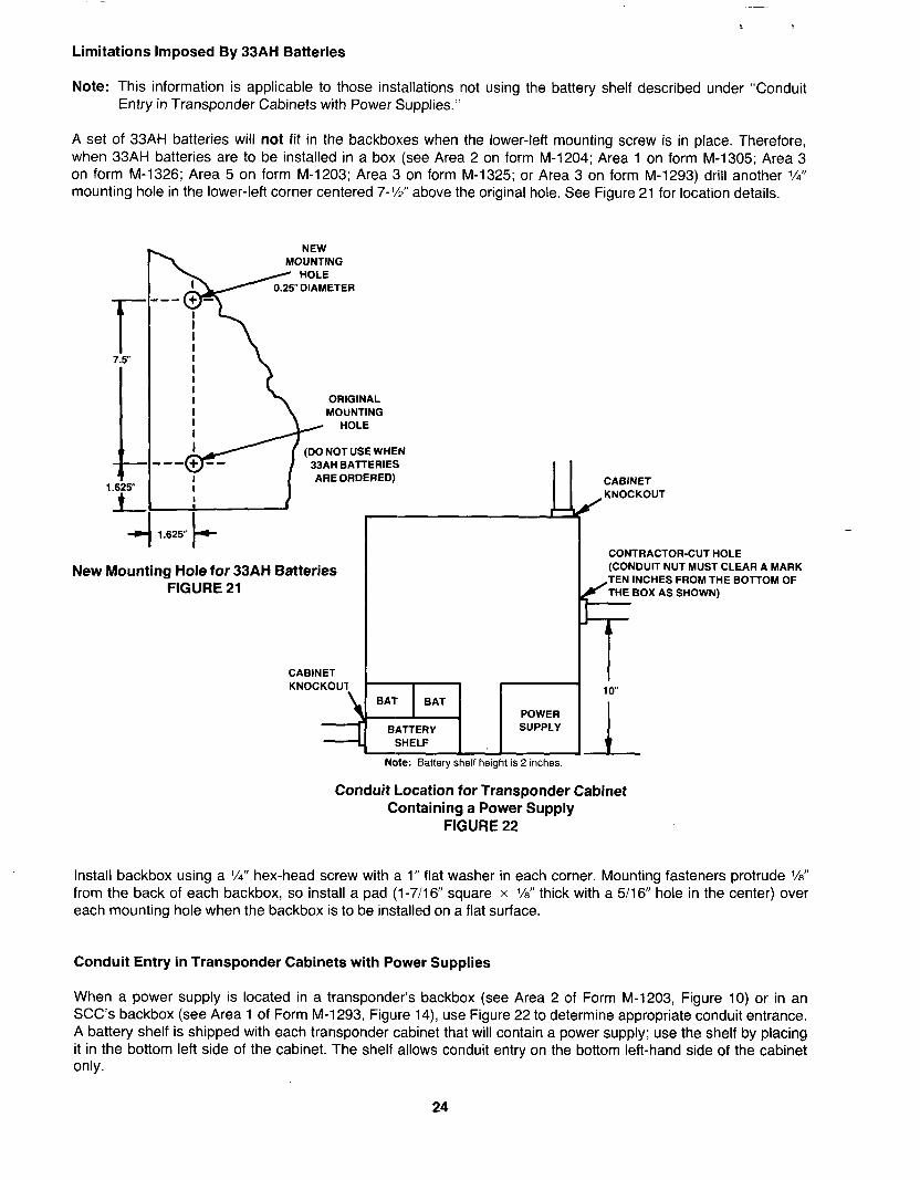
Limitations Imposed By 33AH Batteries
Note: This information is applicable to those installations not using the battery shelf described under “Conduit Entry in Transponder Cabinets with Power Supplies.”
A set of 33AH batteries will not fit in the backboxes when the lower-left mounting screw is in place. Therefore, when 33AH batteries are to be installed in a box (see Area 2 on form M-1204; Area 1 on form M-l 305; Area 3 on form M-1326; Area 5 on form M-1203; Area 3 on form M-1325; or Area 3 on form M-1293) drill another l/4” mounting hole in the lower-left corner centered 7-Y=? above the original hole. See Figure 21 for location details.
f 7.5”
c 1.626”
A--
NEW MOUNTING
/Y %iETER
ORIGINAL MOUNTING
(DO NOT USE WHEN 33AH BAlTERlES ARE ORDERED)
New Mounting Hole for 33AH Batteries FIGURE 21
CABINET KNOCKOUT
CABINET
i/
KNOCKOUT
CONTRACTOR-CUT HOLE (CONDUIT NUT MUST CLEAR A MARK
INCHES FROM THE BOTTOM OF THE BOX AS SHOWN)
Note: Battery shelf height is 2 inches.
Conduit Location for Transponder Cabinet Containing a Power Supply
FIGURE 22
Install backbox using a X” hex-head screw with a 1” flat washer in each corner. Mounting fasteners protrude %” from the back of each backbox, so install a pad (l-7116” square x l/8” thick with a 5116” hole in the center) over each mounting hole when the backbox is to be installed on a flat surface.
Conduit Entry in Transponder Cabinets with Power Supplies
When a power supply is located in a transponder’s backbox (see Area 2 of Form M-1203, Figure 10) or in an SCC’s backbox (see Area 1 of Form M-l 293, Figure 14), use Figure 22 to determine appropriate conduit entrance. A battery shelf is shipped with each transponder cabinet that will contain a power supply: use the shelf by placing it in the bottom left side of the cabinet. The shelf allows conduit entry on the bottom left-hand side of the cabinet only.
24
.
SYSTEM WIRING
This section provides a description of all system wiring diagrams provided with your 2120 system. These drawings include:
l System interconnection drawings for the communications channels, any audio/phone lines, and all powering.
o Equipment cabinet drawings showing component locations and external (contractor) connections.
l M-21 20 and M-2120-ET (if applicable) initiating wiring diagrams.
We will discuss each of these drawings separately.
Note: The drawings discussed in this section are samples only. Each individual 2120 system has its own set of drawings similar to the ones shown in this manual.
System Interconnection Drawings
Each 2120 system is provided with a set of specific system interconnection drawings. These drawings include:
l Communications channel, or data line, interconnections.
0 Power line interconnections.
l Audio line interconnections (if applicable).
l Telephone line interconnections (if applicable).
o A cabinet interconnection and drawing list.
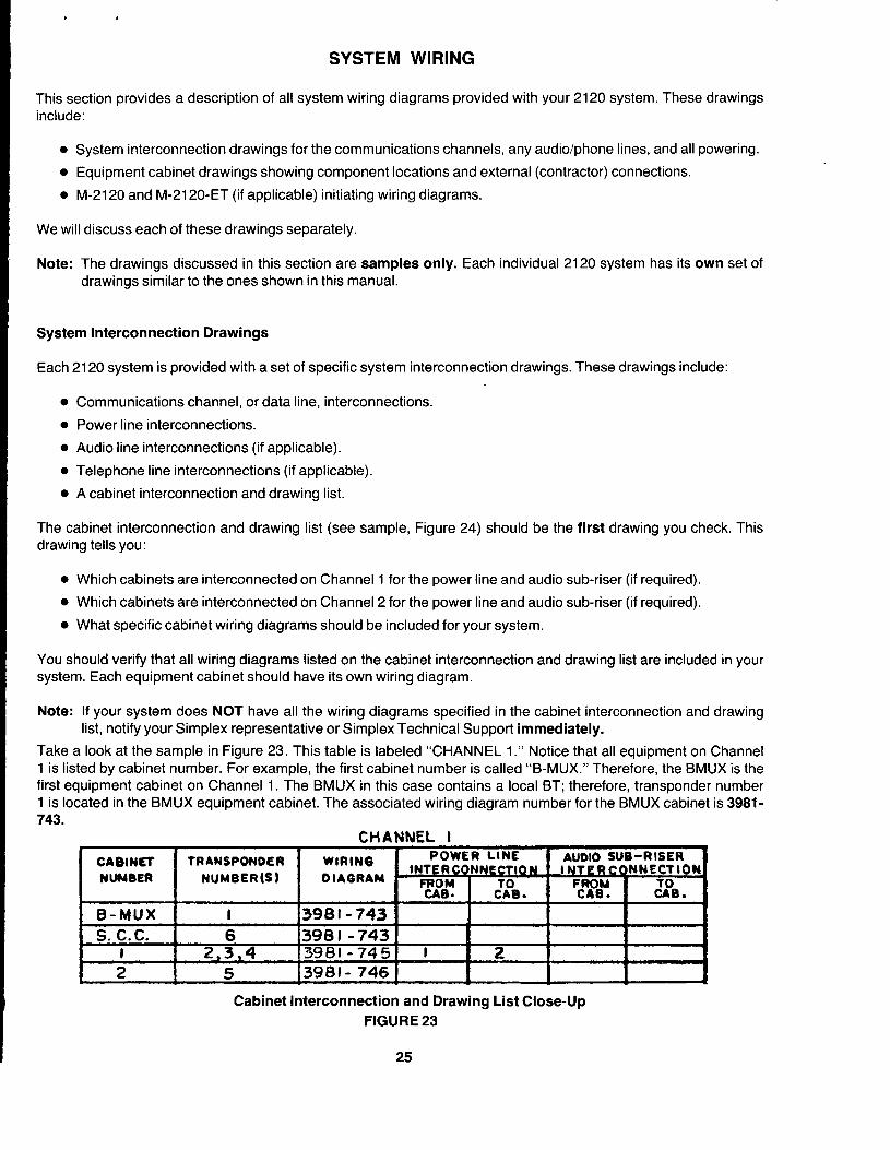
The cabinet interconnection and drawing list (see sample, Figure 24) should be the first drawing you check. This drawing tells you:
l Which cabinets are interconnected on Channel 1 for the power line and audio sub-riser (if required).
l Which cabinets are interconnected on Channel 2 for the power line and audio sub-riser (if required).
l What specific cabinet wiring diagrams should be included for your system.
You should verify that all wiring diagrams listed on the cabinet interconnection and drawing list are included in your system. Each equipment cabinet should have its own wiring diagram.
Note: If your system does NOT have all the wiring diagrams specified in the cabinet interconnection and drawing list, notify your Simplex representative or Simplex Technical Support immediately.
Take a look at the sample in Figure 23. This table is labeled “CHANNEL 1.” Notice that all equipment on Channel 1 is listed by cabinet number. For example, the first cabinet number is called “B-MUX.” Therefore, the BMUX is the first equipment cabinet on Channel 1. The BMUX in this case contains a local BT; therefore, transponder number 1 is located in the BMUX equipment cabinet. The associated wiring diagram number for the BMUX cabinet is 3981- 743.
CHANNEL I
Cabinet Interconnection and Drawing List Close-Up FIGURE 23
25

The second cabinet on Channel 1 contains the SCC. The SCC’s transponder number is 6. Its associated wiring diagram number is 3981;743.
Now . . . look at the third entry in the table. The cabinet number is specified as “1. ” That means that this cabinet contains transponders. Under the “TRANSPONDER NUMBER(S)” column, we see that transponder numbers 2, 3, and 4 are included in cabinet number 1. The wiring diagram number for this cabinet is 3981-745. Notice also that the “POWER LINE INTERCONNECTION” column indicates that the line from cabinet number 1 is used to provide power for the equipment in cabinet number 2.
The fourth entry in the first table refers to cabinet number 2. You can see that transponder number 5 is included in this cabinet. The wiring diagram number for cabinet number 2 is 3981-746. Also, we know that the transponder located in cabinet number 2 is powered by equipment located in cabinet number 1 (see table entry for cabinet number 1).
The table for Channel 2 is interpreted in the same way. The information provided on this drawing for your system, will be quite similar.
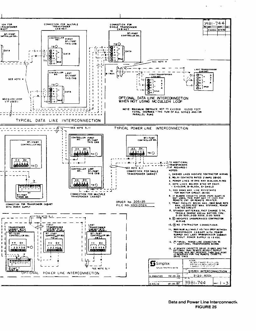
Data and Power Line Interconnections
Data and power line interconnections are illustrated on the same system interconnection drawing (see sample, Figure 25). This system interconnection drawing also includes:
l Local BT Monitor and Control Point wiring (if the BMUX is equipped with a local BT).
l RS232C port numbers and remote device connections.
l Celestra clock connections (if the BMUX is equipped with a Celestra interface board).
On this system interconnection drawing, all contractor wiring is denoted by dashed lines. The connections illustrated are “typical” . . . meaning that you must determine the way in which your system is configured for each data and power line interconnection.
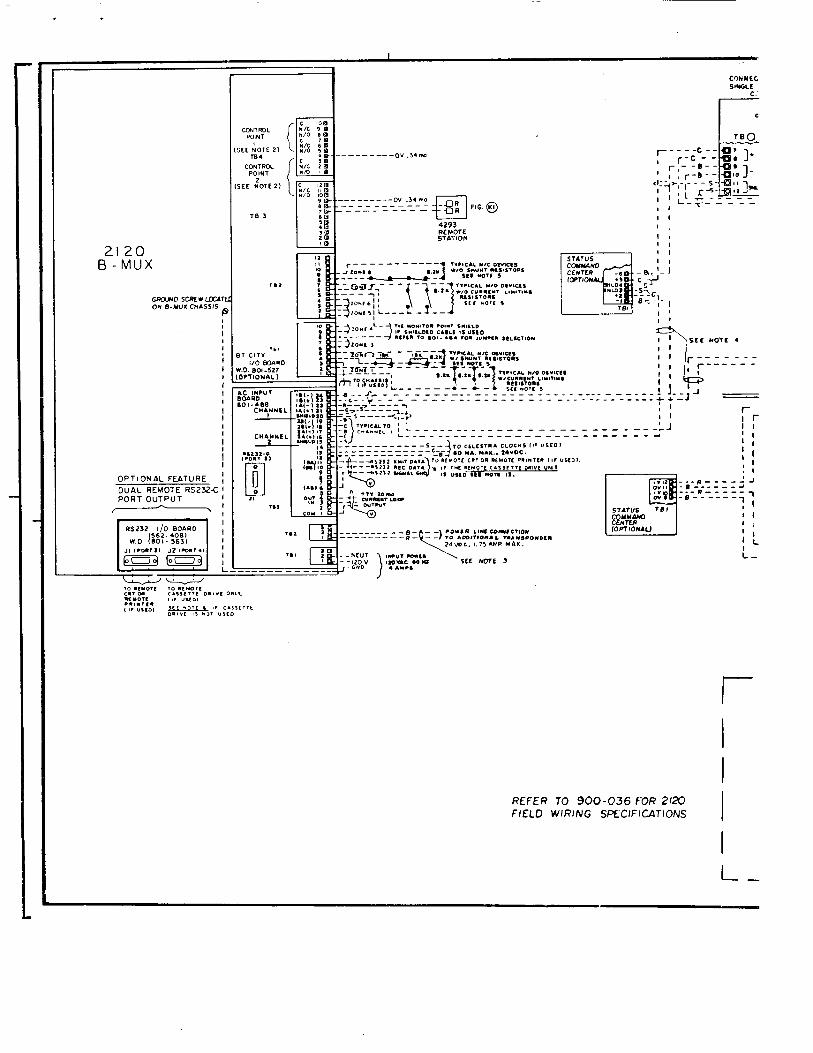
The circled portion of Figure 25 is shown enlarged in Figure 26. Here, the BMUX local BT and AC I/O board connections are shown. In the case of local BT connections (TB2 and TB3 in Figure 26), a reference is made to “FIG. Kl .” This refers to Figure Kl on the M-21 20 initiating wiring diagram. Refer to this diagram to determine how to connect the external device(s) required to the local BT I/O board.
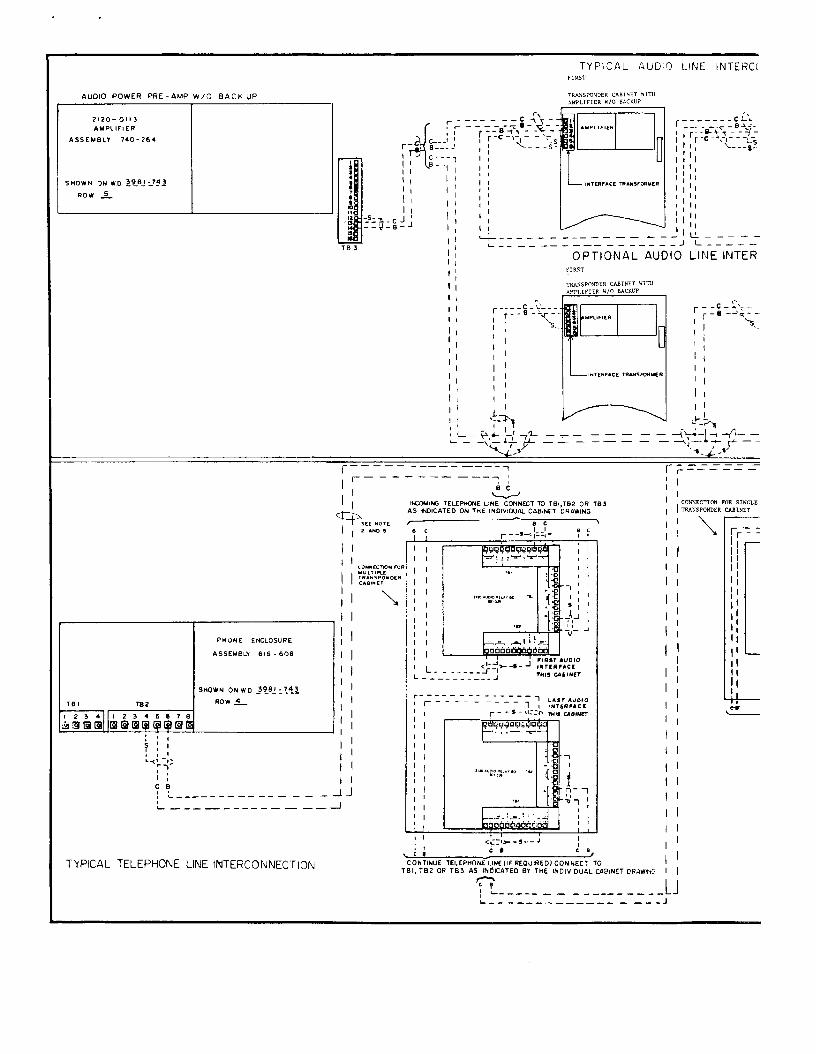
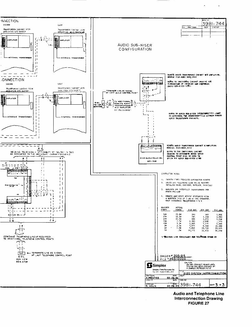
Audio and Telephone Line Interconnections
Audio and telephone line interconnections (if applicable to your system) are listed on the same system interconnection drawing (see sample, Figure 27). This system interconnect drawing also shows how the audio Control Points can be wired (the audio sub-riser configuration). However, specific audio Control Point wiring is shown in the system’s individual cabinet drawings.
On this system interconnection drawing, all contractor wiring is denoted by dashed lines. The connections illustrated are “typical” . . . meaning that you must determine the way in which your system is configured for each audio and telephone line interconnection.
26
2120 B-MUX
OPTIONAL FEATURE ;
DUAL REMOTE RS232-C ) PORT OUTPUT
-!
.- ------- 0” ,,,mo -- -- ------- FIG. @
4293 REMOTE STATION
r
I
I
REFER 70 900-036 FOR 2120 FIELD WIRJNG SPEClFlCATlONS 1
I
L-
r-
? SCL NOTE 4 i
‘I ’ I ’ I ’ I 0fTlOtdA~ DATA LINE INTERCONNECTION
’ ’ I
WHEN NOT USING MCCULOH LOa” ‘1 .I a
6
--- ‘J c ~:-----~---~-~-~-----: II - - -1 : ; ’
-__ --------_-_------------~___ J I
I --- -_-- ----- ------------------.I
NOTL: YAXIYUY WTAhCE MOT TO EXCEL0 10.000 FEET TOTAL OISP+ICE ‘WE SUM OF ALL SERIES IWO/OR PARALLLL RlnS
TYPICAL DATA LIfsE INTERCONNECTION
---------------- UT-
SLL NOTL 3.II _---- ____------- TYPICAL POWER LINE INTERCONNECTION
r-- -- --)A’ ; I I
; r-- - -a--; J L _ _ _ -~--- 10 Aoo1r~0YIL
L _ _ _ _ - - -I--- ?n~‘poNDLIS L NOTL 3.1’ > ‘1) Iwu1nco 1
COWECTION FOR WCLE NOTES:
TRANSPONDER CNIINET ’ I
I. OISNCO LINES INOICATI CONTlACTO” WlllYE
2. “,.LLl CONTACTS RITCO t UPS ZUYDC I I ’ I
3, POWL” LINES I6 A16 “.I. e.eLlc6.l.mcl
’ I 4. OAT. LINES e‘LW* 676.0 0” LG”,“.
1 I - C*CLL*m, e.eLICx, s. WILL0
-.
L-“------J CONNECTION FOR WLTIPLE TRANSPOHOER CAEINET
ORDER No. 205 I85 FILE NO. H93t002A
----------
r ----- ~yni. -- - --f 1
I ) S’T-3El.I INTERCONNFCTION :. I ,,
“.PRENTISS 02-28-83 2120 -8201 :.I, .<. 2 I
AL POM ER LINE INTERCOtiNECTlON _---- ---
Data and Power Line lnterconnectic FIGURE 25
AUDIO POWER WE-AMP W/O BACK UP
<
TYPICAL AUDlQ LINE INTERC( FIRST
------CL .- - -_ r.-e++i-- v-f- r-C-At-t---‘- ‘I L-;.s ‘I
I--- IT--
$ ,
g--y! J c---, 0--, 1,
I I ‘I 1 I It II II CL-----
L-----
LINE INTER ~--me------ ____ --e-J
OPTIONAL AUDIO
r--C-:‘+-
I r-
0 -Aq- -
I ’ ‘5.
’ I
1 I
’ I
’ I
I I
I I
r----c r--0
I ;
I ’ I 1
1 I ’ I I I
I!
; I-------- ----_ -- - _JJ L - __ _ _ ___ _ _ _ _ _ -I
L-----------A- - ---
T’fPICAL TELEPHONE LINE IhlTERCONNECTi3N
--------J
GJNECTI~N SECOND
--------II -------A
AUDIO SUB-RISER CONFIGURATION
0~~~~‘205185 F,LE l H93 1002A
-. _.-
.-LO s. NOLtN oz.&%] 398 I-744 tin3 -3
Audio and Telephone Line Interconnection Drawing
FIGURE 27
I 1 I
ONrRlCrOR CONNECTION EFER TO NOTE , F,C, -
ST&TVS COMMAND CENTER
ASSEMBLY 616-623
a
-0YI
4 ROW 3
-+v I
CONTA CTOR C0NNEC110NS REFER TO NOTE ,FIG __
.Th LIKE
FIG
@
FIG
0
A
ORDERff 128507 F,LE bE92237lA
SCC Cabinet Drawing FIGURE 29
.
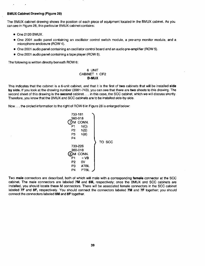
BMUX Cabinet Drawing (Figure 28)
The BMUX cabinet drawing shows the position of each piece of equipment located in the BMUX cabinet. As you can see in Figure 28, this particular BMUX cabinet contains:
l One 2120 BMUX.
l One 2001 audio panel containing an oscillator control switch module, a pre-amp monitor module, and a microphone enclosure (ROW 4).
l One 2001 audio panel containing an oscillator control board and an audio pre-amplifier (ROW 5).
l One 2001 audio panel containing a tape player (ROW 6).
The following is written directly beneath ROW 6:
6 UNIT CABINET 1 OF2
B-MUX
This indicates that the cabinet is a 6-unit cabinet, and that it is the first of two cabinets that will be installed side by side. If you look at the drawing number (3981-743), you can see that there are two sheets to this drawing. The second sheet of this drawing is the second cabinet. . . in this case, the SCC cabinet, which we will discuss shortly. Therefore, you know that the BMUX and SCC cabinets are to be installed side-by-side.
Now. . . the circled information to the right of ROW 6 in Figure 28 is enlarged below:
733-l 81 360-018
0 7 M CONN.
Pl 1 (C) P2 l(S) P3 1 (B) P4
733-226 360-018
0 8 M CONN.
Pl +VB P2 ov P3 ATBL P4 PTBL
) TO SCC
Two male connectors are described, both of which will mate with a corresponding female connector at the SCC cabinet. The male connectors are labeled 7M and 8M, respectively; once the BMUX and SCC cabinets are installed, you should locate these M connectors. There will be associated female connectors in the SCC cabinet labeled 7F and 8F, respectively. You should connect the connectors labeled 7M and 7F together; you should connect the connectors labeled 8M and 8F together.
39
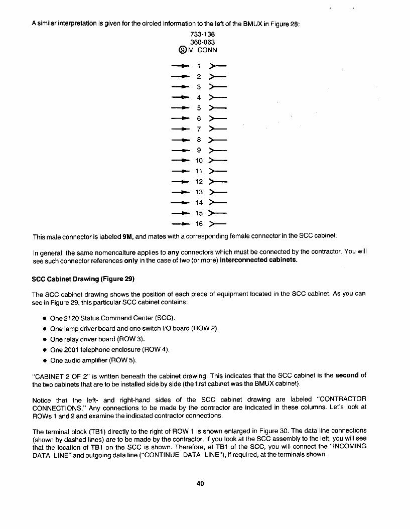
A similar interpretation is given for the circled information to the left of the BMUX in Figure 28:
733-l 38 360-063
@M CONN
-1
-2
-3
-4
-5
-6
-7
-8
-9
- 10
-)- 11
_c 12
+ 13
- 14
- 15
- 16
This male connector is labeled 9M, and mates with a corresponding female connector in the SCC cabinet.
In general, the same nomencalture applies to any connectors which must be connected by the contractor. You will see such connector references only in the case of two (or more) interconnected cabinets.
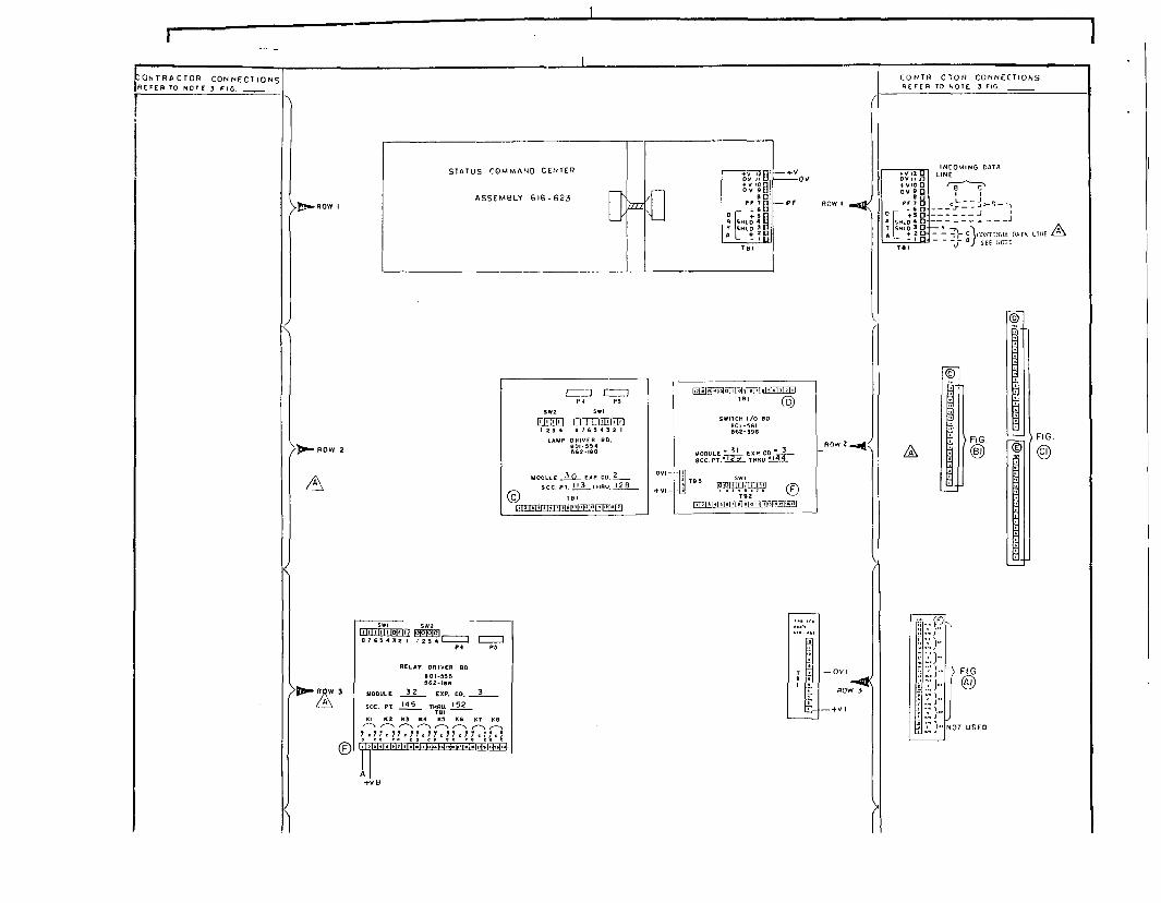
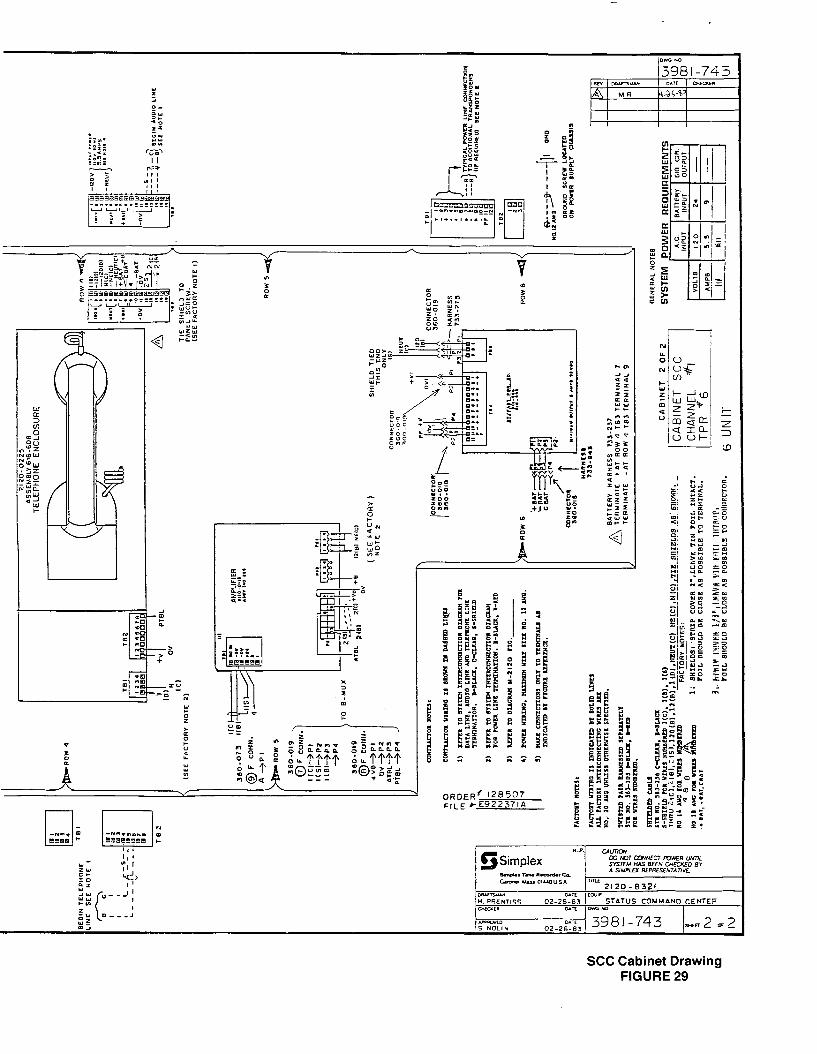
SCC Cabinet Drawing (Figure 29)
The SCC cabinet drawing shows the position of each piece of equipment located in the SCC cabinet. As you can see in Figure 29, this particular SCC cabinet contains:
l One 2120 Status Command Center (SCC).
l One lamp driver board and one switch I/O board (ROW 2).
l One relay driver board (ROW 3).
l One 2001 telephone enclosure (ROW 4).
l One audio amplifier (ROW 5).
“CABINET 2 OF 2” is written beneath the cabinet drawing. This indicates that the SCC cabinet is the second of the two cabinets that are to be installed side by side (the first cabinet was the BMUX cabinet).
Notice that the left- and right-hand sides of the SCC cabinet drawing are labeled “CONTRACTOR CONNECTIONS.” Any connections to be made by the contractor are indicated in these columns. Let’s look at ROWS 1 and 2 and examine the indicated contractor connections.
The terminal block (TBl) directly to the right of ROW 1 is shown enlarged in Figure 30. The data line connections (shown by dashed lines) are to be made by the contractor. If you look at the SCC assembly to the left, you will see that the location of TBl on the SCC is shown. Therefore, at TBl of the SCC, you will connect the “INCOMING DATA LINE” and outgoing data line (“CONTINUE DATA LINE”), if required, at the terminals shown.
40

Now look at the contractor connections to the right of ROW 2, shown enlarged in Figure 31. The first terminal block (the shorter one) has two designations. A “@” is written on the terminal block itself, and “FIG. Bl” appears directly to the right of this terminal block. The “0 ” is a reference letter; if you look at the lamp driver oard in ROW 2, you will see a corresponding terminal block designated “0 .” So. . the terminal block labeled ” C ” to the right 6 of ROW 2 is located on the lamp driver board. The “FIG. Bl ” designation refers to Figure Bl in the M-21 20 initiating wirfng diagrams.
The terminal blocks designated I’@” and ‘@” are interpreted in the same way. These terminal blocks are located on the switch I/O board, and you make connections to these terminal blocks as shown in Figure Cl in the M-21 20 initiating wiring diagrams.
All the remaining contractor connections on the left- and right-hand sides of the SCC cabinet drawing are interpreted in the same way as the examples presented here. This includes any power line wiring (if required) and audio/telephone wiring (if required).
Transponder Cabinet Drawings - Sample 1 ‘\
Each 2120 transponder cabinet is supplied with its own cabinet drawing. This drawing shows the position of each piece of equipment located in the transponder cabinet, as well as all contractor connections for each transponder in the cabinet. We are going to examine two such cabinet drawings.
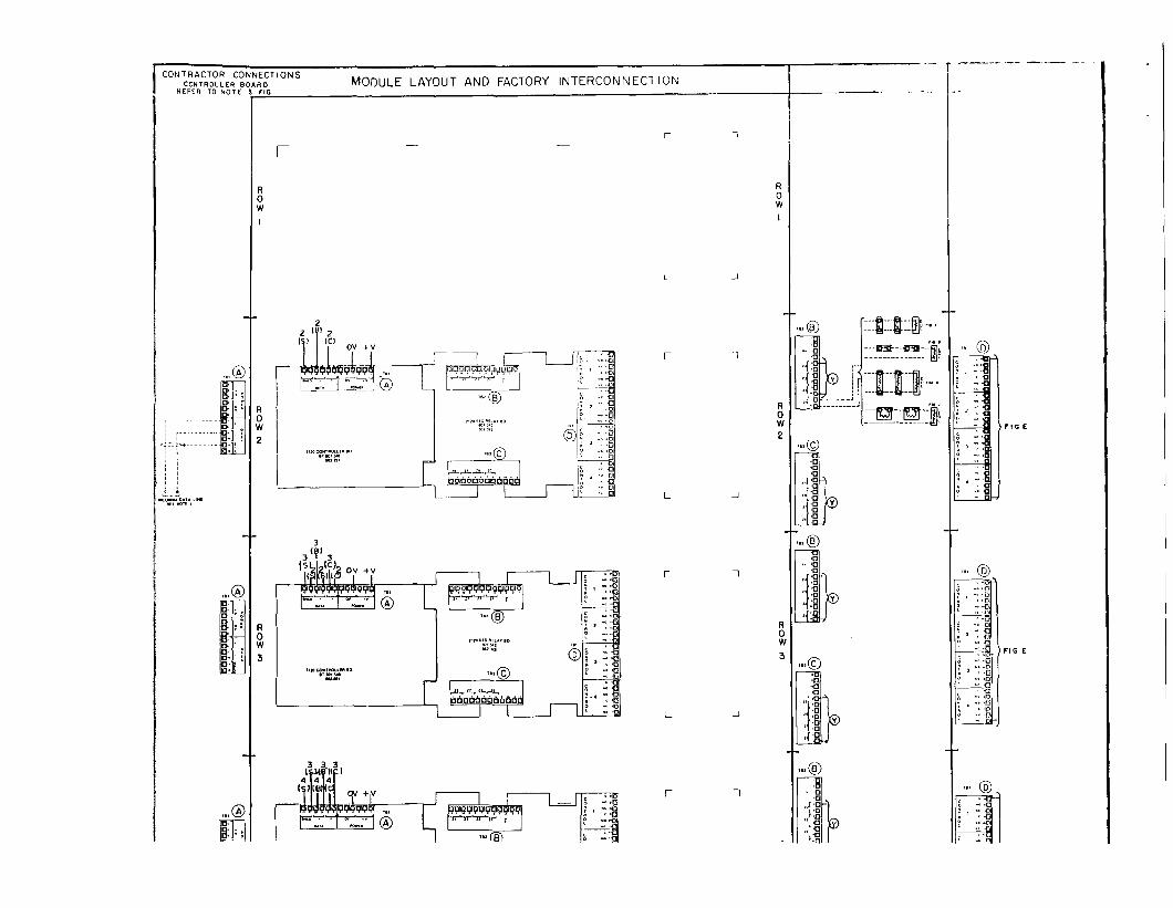
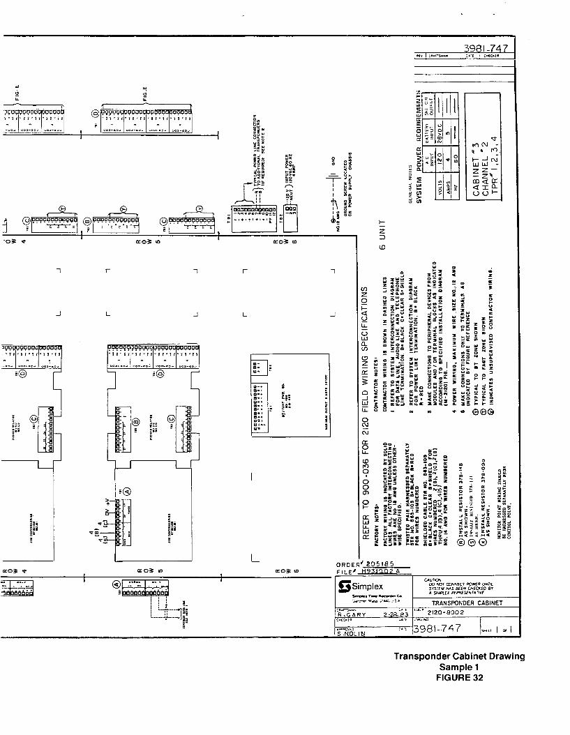
Take a look at Figure 32. This transponder cabinet drawing shows four basic transponders (BTs), each of which uses a standard relay board for Monitor and Control Point wiring. The cabinet is also equipped with a “BT/FABT PWR BD” (ROW 6). Notice that the left-hand side of this transponder cabinet drawing is labeled “CONTRACTOR CONNECTIONS.” The illustrations in this column show the data line connections for the units in this cabinet. Let’s take a closer look at the connections shown.
The terminal block to the left of ROW 2 (TBl) is shown enlarged in Figure 33. Notice that the reference letter “@” appears directly above this terminal block. If you lo k at the BT controller board shown in ROW 2 (Figure 32), you can see a corresponding terminal block labeled “ 6 A .” So the terminal block labeled “@” to the left of ROW 2 is located on the BT controller board.
You should make the “INCOMING DATA LINE” connections to this terminal block as shown.
Now. : . the terminal block labeled “ @ ” to the left of ROW 5 is shown enlarged in Figure 34. This terminal block is located on the BT controller board in ROW 5. You should make the connections for the outgoing data line (“CONTINUE DATA LINE”) as shown.
Note: The incoming and outgoing data line connections are made at the first and last transponders in the cabinet, respectively. The data lines between the four transponders are factory-connected.
Looking at Figure 32 again, you can see that the right-hand side of this cabinet drawing is broken up into two columns. The first column illustrates the contractor connections for the Monitor Points on each transponder. The second column illustrates the contractor connections for the Control Points on each transponder. Let’s look at the Monitor and Control Point connections shown for the transponder in ROW 2.
The contractor connections to the right of ROW 2 are enlarge in Figure 35. Connections for the first four Monitor Points are made at terminal block TB2. The reference letter “ 8 B ” tells you that this terminal block is located at the top of the standard relay board shown in ROW 2 of Figure 32. The bottom two terminals can be connected as shown in the sample to the right of TB2. Notice that each sample has a reference figure number beside it. These referenced figures are located in the 2120 initiating wiring diagrams . . refer to the reference figure to determine the proper way to connect the monitored devices to the Monitor Point. As indicated by the ” Y ” designation, the 8 three remaining Monitor Points on this terminal block are connected just like the sample shown for the first Monitor Point.
41
Beneath TB2 in Figure 35 is the terminal block for the last four Monitor Points (TB3), designated by a “@.” The “ C ” tells you that this terminal 0 lock is located at the bottom of the standard relay board shown in ROW 2 of Figure 32. As indicated by the ” 6 Y ” designation, the Monitor Points on TB3 are connected just like the sample shown for TB2.
Connections for the BT’s Control Points are made at terminal block TBl, as shown in Figure 35. The reference letter ” 0 D ” tells you that TBl is located on the right-hand side of the standard relay board shown in ROW 2 of Figure 32. Notice that this terminal block has “FIG E” written beside it. “FIG E” refers to Figure E in the M-2120 initiating wiring diagrams. See the referenced figure to determine the proper way to connect external devices to the Control Points.
We have only described contractor connections for the first transponder in this particular cabinet. However, all contractor connections are interpreted in the same way. For each transponder, be sure to:
l Check both sides of the drawing for contractor connections.
l Use the designated reference letter to physically locate the terminal block.
l Refer to the data and power line system interconnection drawing to determine the possible source and destination of data and power lines.
l Refer to referenced figures in the M-21 20 initiating wiring diagrams to see how you connect external devices to a transponder’s Monitor and Control Points.
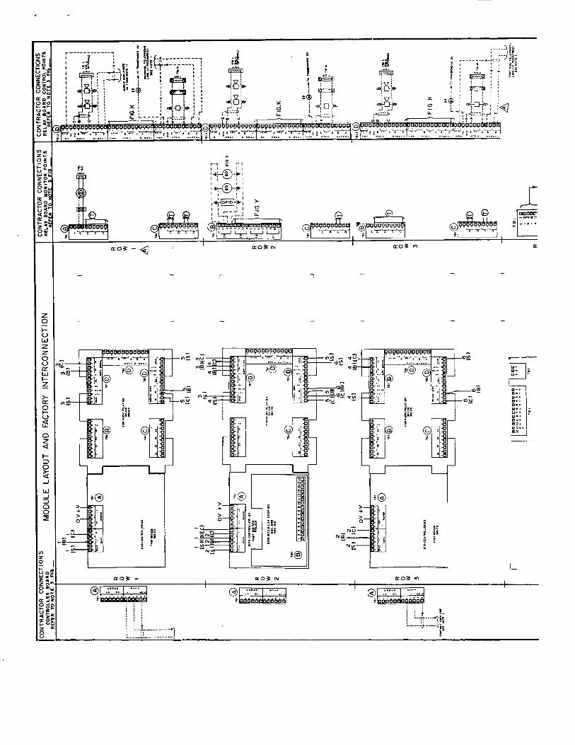
Transponder Cabinet Drawings-Sample 2
We have discussed one sample of a 2120 transponder cabinet drawing. All such drawings are interpreted in much the same way. However, there are two other aspects of 2120 systems that need some discussion: the audio sub- riser configuration, and the telephone line interconnection.
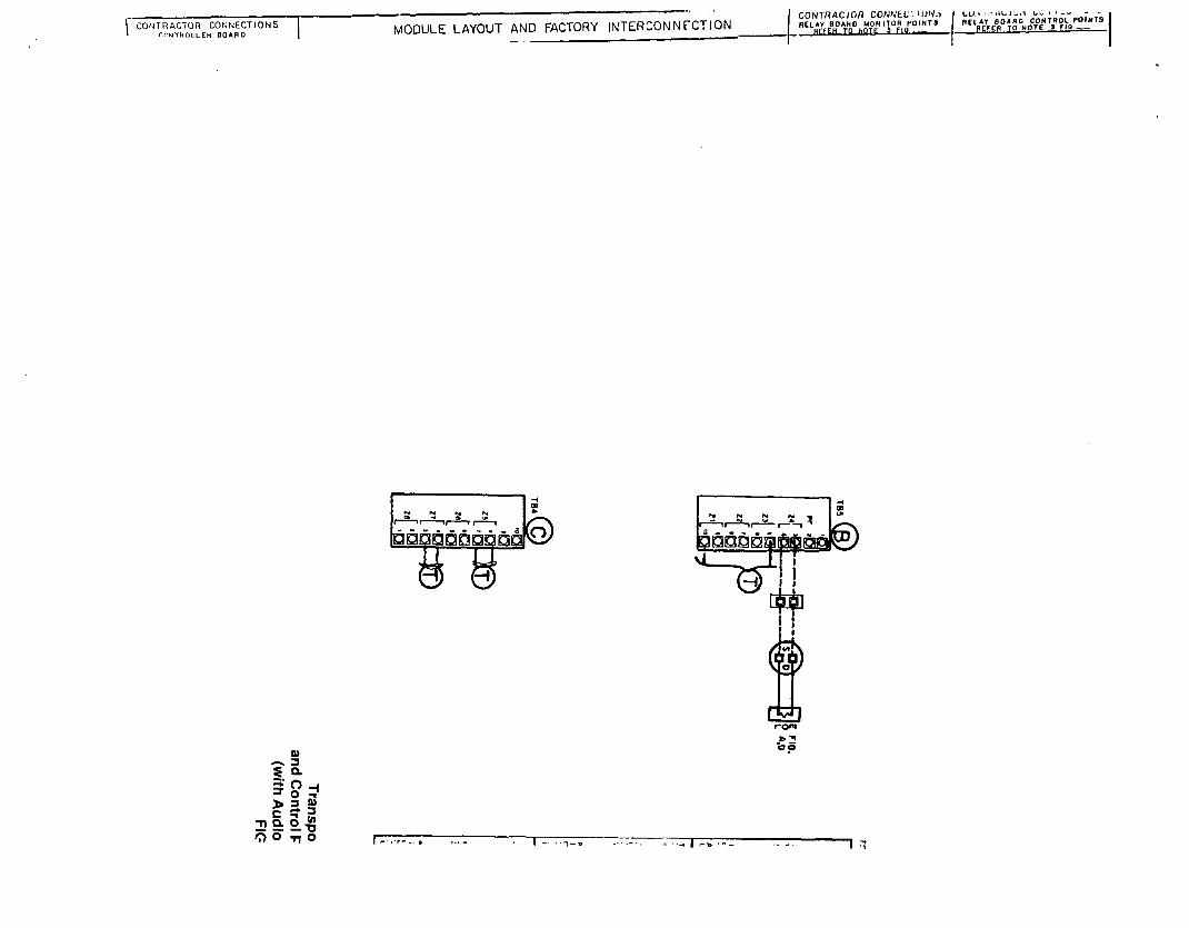
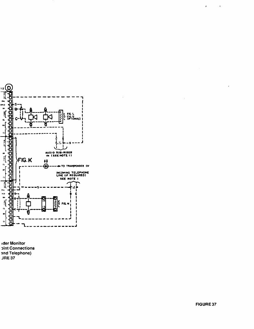
Take a look at Figure 36. The transponder cabinet shown is quite similar to the one in Figure 32; the only difference involves the audio and telephone line connections shown. Let’s focus on the contractor connections shown in the second column to the right of ROW 1 (“CONTRACTOR CONNECTIONS/RELAY BOARD CONTROL POINTS”). These connections are enlarged in Figure 37.
The terminal blocks shown in Figure 37 (TBl through TB3) are located on the audio relay board in ROW 1, as indicated by the reference letter ” 0 D .” The Control Points on TBI are connected to speaker circuits for the 2120 audio system. Notice that the incoming audio line (“AUDIO SUB-RISER IN”) is also connected to terminals on TBl. Therefore, the speaker circuits connected to TBl are fed by the 2120 audio sub-riser. Refer to the audio and telephone line system interconnection drawing to determine the possible source of the incoming audio line.
Moving on to TB2, you can see that connections to this terminal block are made according to “FIG K” in the M-2120 initiating wiring diagrams.
Finally, look at TB3. Connections for the incoming telephone line are made at this terminal block, along with the associated telephone circuit. The telephone circuit itself is connected according to “FIG M” in the M-2120 initiating wiring diagrams. Refer to the audio and telephone line system interconnection drawing to determine the source of the incoming telephone line.
In Figure 36, the telephone line continues from the last transponder at the cabinet; the audio line ends at the last transponder in the cabinet (ROW 3). If there had been other audio speaker circuits in the system, the outgoing audio line would have been connected to appropriate terminals on TBl in ROW 3.
42
CONTRACTOR U CONTROLLER
HEFtA TO NOTC
ECTIONS ID MODULE LAYOUT AND FACTORY INTERCONNECT IOk
r - - r 7
F
:
J
r 1
.-
J L L
i- .Pg.C, S NOLIN
-A-: 13981-747 I w I
Transponder Cabinet Drawing Sample 1
FIGURE 32
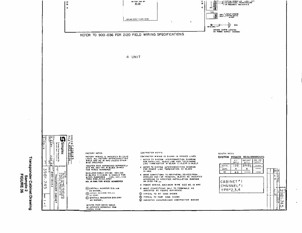
4 UNIT
FACTOR” wIRI*G IS lNOlClTE0 a” SOllO CoNTRdCTOe WlRlNO IS SrlOWN Ik 0AS”E0 LIMES LlNES ALL FACTOR” ,NTERCONNECTlkO SYSTEM POWER REQIIIREMENTS WIRES ARE NO 18 AWG UNLESS OTtlER- I REFER TO SlSTEY ,NTERCONNECTlON DlAORlY WISE SPEClFlEO FOR DATA LIr4E, &“DIO LINE AND TELEPHONE
LlHE TERMlNATlON 8. .9LAClc C=CLE*R S=WIELD ,w,S,ED PAIR HARNESSED SEPARATELY STR NO. S63-10s a=aLAcK R=RED z REFER TO SISTEM ,NTERCONNECTlON DII\ORAM FOR WIRES NUMBERED FOR POWER LINE TERMINATION. B= BLACK
R . RED
HO. 14 liwo FOR WIRES NUMBERED ‘Y-2120) [email protected] CABINET8 1
. . I- MODULE LAYOUT AND FACTORY INTERSON N t-CT I ON
CONTf?AC/CiR CONNtL’ lUlV., LU,,I,~,l,L.,~L,~, LLSI (_I ” - LONTRACTOR CONNECTIONS RELAY BDA”0 MONITOR POINTS RELAY BOAR0 CONTROL POINTS
I-“NTAOLLEA BO&AO REFER TO NOTE S FIO -
I I
1
AU010 SUB-RISa I” I SEE NOTE I )
INCOMINQ TELEPHONE LINE (IF REOUIR~D)
Stt NOTE I
i I i
lder Monitor Dint Connections l d Telephone) JRE 37
FIGURE 37

Expanded Transponder Cabinet Drawings (Figure 38)
The expanded transponder (ET) cabinet drawings are similar to the “standard” transponder cabinet drawings we have already discussed. The left- and right-hand sides of the ET drawings are devoted to contractor connections. The terminal blocks illustrated have reference letters so that you can easily locate each terminal block on the ET itself. Similarly, figure references to M-2120-ET initiating wiring diagrams are made at each Monitor and Control Point terminal block for appropriate contractor connections.
Note: The M-2120-ET initiating wiring diagrams are not the same as the M-21 20 initiating wiring diagrams. DO NOT CONFUSE THE TWO.
The ET cabinet drawing also uses numerical references enclosed in squares (e.g., q ). There are many circuit boards located in an ET, and these boards are numbered for easy reference. Therefore, when you see a numeric reference next to a terminal block in the contractor connections column, look for the corresponding number on the cabinet layout. In this way you can easily relate each set of contractor connections to the associated ET circuit board.
55
INSTALLATION GUIDE
So far in this publication, we have discussed the various documents that are supplied with every new 2120 system. After studying the examples provided, you should be able to accurately interpret the documents supplied with your system. Remember: even though there may be many documents provided, they are all interpreted in the same way as the examples in this publication.
Now that you know how to interpret system documentation, we need to spend some time discussing the installation itself. Therefore, this segment of the manual is devoted to a general guide for all 2120 installations.
Installation Precautions
Before you install any part of a new 2120 system, there are precautions you need to know and apply to your particular installation. These precautions are listed below; if you adhere to the rules they provide, your installation should proceed smoothly and safely.
A. Used twisted, shielded pair for the following:
l Data lines.
l Audio and telephone lines.
. RS232C ports.
Note: Monitor Point wiring may or may not require twisted, shielded pair. Refer to the 2120 Field Wiring Specifications (900-036) for specific recommendations.
B. Each equipment cabinet should be connected to building ground via a single, unbroken conductor (12AWG wire, typical).
C. DO NOT MAKE ANY CONNECTIONS TO BASIC TRANSPONDERS (BTs), FIRE ALARM BASIC TRANSPONDERS (FABTs), OR EXPANDED TRANSPONDERS (ETs) WITH POWER APPLIED. This includes all Monitor and Control Point wiring.
D. Before applying power to new equipment:
l Verify that power connections have been terminated at the proper terminals.
l Verify that equipment with a mixture of high and low voltages has all connections properly terminated (for example, transponders containing low-voltage Monitor Point wiring and high-voltage Control Point wiring).
l Verify that all wiring is free of grounds.
E. Apply power to equipment ONLY in the presence of a qualified Simplex Technical Representative and in the following sequence:
1. Apply AC power first.
2. Apply battery power last.
Reverse this sequence when you power down equipment.
F. NEVER APPLY OR DISCONNECT EQUIPMENT POWER BY USING AN INTERCONNECT PLUG.
G. Do not remove the end-of-line (EOL) resistors on transponder Monitor Points until you are ready to install the Monitor Point wiring.
56
Installation Guide
The following is a set of recommended procedures to following during installation. Before you begin wiring the system:
l Ensure that all system interconnection and wiring diagrams required for your system are provided.
l All backboxes (cabinets) and the associated equipment should be properly installed AND grounded via a single, unbroken conductor (12AWG, typical). Conduit ground is NOT sufficient.
1. Connect the data line between all equipment first. To do so, you must:
l Refer to the 2120 General System Features form to see whether each data line equipped is single line (one pair of wires, with shield, option number 6201) or McCulloh loop (two pairs of wires, with shields, option number 6202).
l Refer to the appropriate system interconnection diagram to see how cabinet-to-cabinet connections are made.
l Refer to the individual equipment cabinet drawings to determine how the data line is terminated at each equipment cabinet.
2. Next, connect the audio lines (if audio is equipped) between all equipment associated with the audio system. To do so, you must:
l Refer to the cabinet interconnection and drawing list (part of the system interconnection drawings) to see which equipment cabinets are interconnected for the audio sub-riser configuration.
l Refer to the appropriate system interconnection diagram to see how cabinet-to-cabinet audio connections are made.
l Refer to the cabinet drawings specified in the cabinet interconnection and drawing list to determine how the audio sub-riser is connected to audio Control Points at each equipment cabinet.
3. Connect the telephone lines (if telephone is equipped) between all equipment associated with the telephone system. To do so, you must:
l Refer to the appropriate system interconnection diagram to see how cabinet-to-cabinet telephone line connections are made.
l Refer to the appropriate cabinet drawings to determine how the telephone line is terminated at each equipment cabinet. The specification sheet (or transponder specification worksheet, for transponders) for each piece of equipment will tell you if the telephone line is associated with that piece of equipment.
4. Connect the power lines between all equipment cabinets as required. To do so, you must:
l Refer to the cabinet interconnection and drawing list to see which equipment cabinets are interconnected for the power line configuration.
l Refer to the appropriate system interconnection diagram to see how cabinet-to-cabinet power connections are made.
l Refer to the cabinet drawings specified in the cabinet interconnection and drawing list to determine how the power line is connected at each equipment cabinet, if such a connection is required.
57

5. At this point, enough connections have been made for a Simplex Technical Representative (TR) to check out the basic operation of your 2120 system. It is recommended that you contact your local TR and have him verify that all data, audio/telephone, and power line connections have been properly made. Then the TR will have you apply power to the system so that he can verify the operation of the system’s basic components. When the TR has completed his preliminary checkout, power-down all equipment.
6. Wire all external devices for the Monitor and Control Point circuitry. To do so, you must:
l Refer to each equipment cabinet drawing to determine where each transponder’s Monitor and Control Point circuit is terminated.
l Refer to the M-21 20 or M-2120-ET initiating wiring diagrams, as appropriate, to determine how peripheral devices are connected to a transponder’s Monitor and Control Points.
As you finish wiring a group of external devices, verify that your wiring is free from grounds before terminating each circuit to its associated Monitor or Control Point.
Note: Monitor Point wiring includes an EOL resistor at the end of each circuit (with the exception of McCulloh loop Monitor Point circuitry). Therefore, as you connect each Monitor Point to its associated circuit, remove the EOL resistor connected at the Monitor Point terminal (this EOL resistor was installed by the factory).
8. Now that the system is completely installed, you should again contact your local TR. The TR will completely check out your system. Once he has completed his checkout he will either notify you of any wiring problems he encountered, or will let you know that the system is operating properly.
9. Correct any wiring defects the TR found. If no defects were found, then the installation phase of your job is complete. If there were wiring defects, contact the TR after you have corrected the problem and have him verify that your system is now operating properly.
58

I i i

-- t
s3 ,Simplex MUX2-21-003
Simplex Time Recorder Co., l Simplex Plaza l Gardner, Massachusetts 01441 U.S.A. (575-557) 1