2018 MotoTrax · 3 Unboxing the MotoTrax TA — Primary hain And Masterclip T — IDT Strut T —...
19
1 2018 MotoTrax Track Kit Installation Manual
Transcript of 2018 MotoTrax · 3 Unboxing the MotoTrax TA — Primary hain And Masterclip T — IDT Strut T —...

1
2018 MotoTrax Track Kit
Installation Manual

2
Preparing the bike
1) Put the motorcycle on a stand.
2) Remove stock drive chain
3) Remove the rear wheel
4) Remove the mud flap
5) Disconnect the suspension linkage from the lower shock and bike frame (if your bike does not have
a linkage then disconnect the lower shock from the swing arm)
6) If you are using the foot brake disconnect the brake line from the foot brake master cylinder, if you
are using a hand brake then completely disconnect the foot brake master cylinder and brake lever
from the frame.
7) Remove the kickstand if equipped.
8) Remove the swing arm from the bike, clean and lightly grease the swing arm axle as it will be re-
used for kit installation.
9) Remove the shock, note on some bike models it may be necessary to remove the exhaust and/or
loosen the lower sub frame bolts to get the shock out.
Note: consult your motorcycles owner’s manual if you need assistance on any of the above steps!

3
Unboxing the MotoTrax
TA — Primary Chain And Masterclip
TB — IDT Strut
TC — IDT Jam Nut
TD — Front Link Bolts (2X)
TE — Banjo Bolts & Washers (2X)
TF — Track Stay Studs & Nuts (2X)
Ski Box 2 - Track ParTS
TA
TC
TE TD
TF
FA — Stepped Fork Spacer
FB — Strait Fork Spacer
FC — Ski Brackets (2X)
FD — Ski Axle Bolt & Washer
FE — Fork Brace
FF — Left Swingarm Spacer
FG — Right Swingarm Spacer
FH — Strut Spacers (2X)
Ski box 3 - Fit Kit
FF FG
FH
FA
FB
FE
FC
FD
Track Box - Track Assembly

4
After removing the track assembly from the
box, cut the rear banding and zip tie holding
the brake line secure.
Locations of banding and zip tie are shown
in image.
Slide swingarm collars (FF) and (FG) (from fit
kit box) into swingarm mounts as shown
with the flange resting on the inside over the
bulkhead.
Note: Apply a liberal amount a waterproof
grease to the bushings in the bulkhead be-
fore slider the spacers into position.
Spin the IDT strut (TB) onto the strut end as
shown, leave about 1/4” of visible threads
showing below the jam nut, securely tighten
the jam nut at this point.
FF FG
5
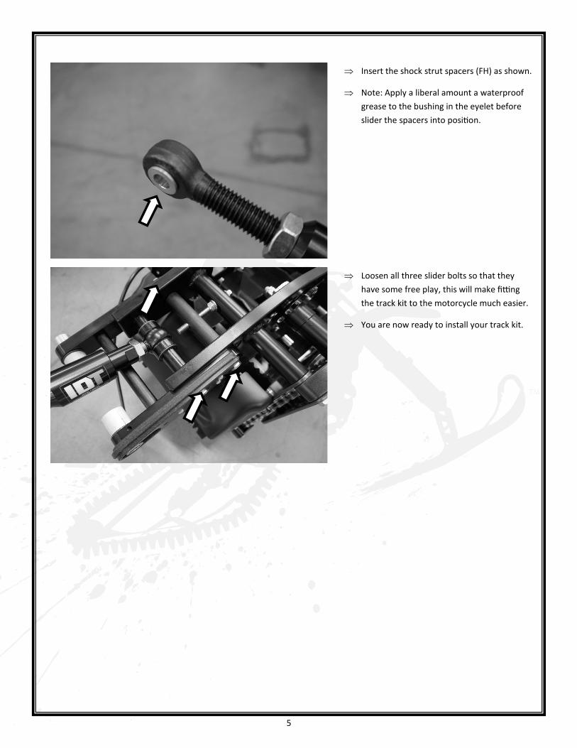
Insert the shock strut spacers (FH) as shown.
Note: Apply a liberal amount a waterproof
grease to the bushing in the eyelet before
slider the spacers into position.
Loosen all three slider bolts so that they
have some free play, this will make fitting
the track kit to the motorcycle much easier.
You are now ready to install your track kit.
6
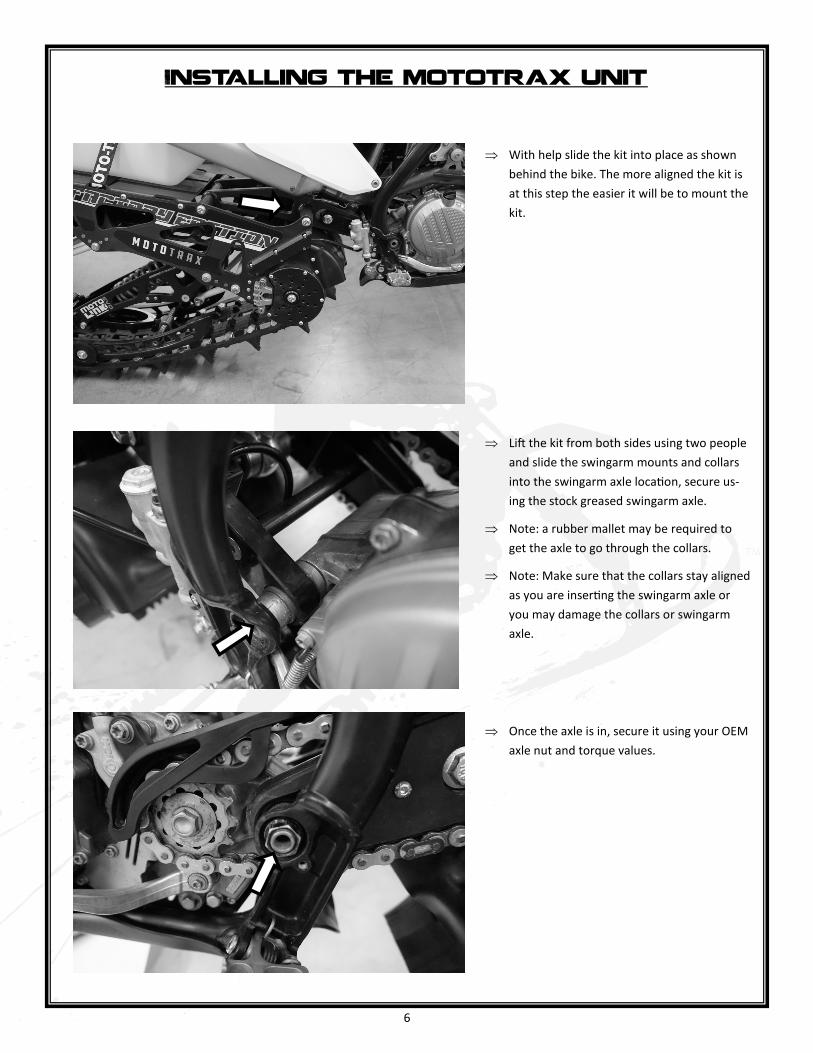
With help slide the kit into place as shown
behind the bike. The more aligned the kit is
at this step the easier it will be to mount the
kit.
Lift the kit from both sides using two people
and slide the swingarm mounts and collars
into the swingarm axle location, secure us-
ing the stock greased swingarm axle.
Note: a rubber mallet may be required to
get the axle to go through the collars.
Note: Make sure that the collars stay aligned
as you are inserting the swingarm axle or
you may damage the collars or swingarm
axle.
Once the axle is in, secure it using your OEM
axle nut and torque values.
Installing the mototrax unit

7
Mount the strut into the upper shock hole as
shown, torque bolt to OEM specs.
Install the front link bolts (TD) and torque to
specs below.
Note: Installing the front link bolts is much
easier with help. One person can line up the
front link and install the bolt while the help-
er is lifting the kit from the rear grab bar as
needed.
Torque: NM: 80.0 F/LBS: 59.0
Use red locking compound.
Now install the primary drive chain (TA)
from the kit to the bike, if the chain is very
loose check to see if you can remove two
links, the chains are intentionally sent long
so that we can accommodate different coun-
ter sprocket size and gearing options.
Once the chain is installed, install the master
clip (TA) as shown, it is important to make
sure the clip is fully seated and oriented as
shown to reduce risk of master clip and
chain failure.
8
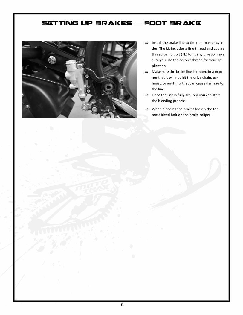
Install the brake line to the rear master cylin-
der. The kit includes a fine thread and course
thread banjo bolt (TE) to fit any bike so make
sure you use the correct thread for your ap-
plication.
Make sure the brake line is routed in a man-
ner that it will not hit the drive chain, ex-
haust, or anything that can cause damage to
the line.
Once the line is fully secured you can start
the bleeding process.
When bleeding the brakes loosen the top
most bleed bolt on the brake caliper.
Setting Up Brakes — Foot Brake

9
Route the brake line through the track sys-
tem and around the strut as shown making
sure it is clear of the drive chain, exhaust and
anything else that my snag, tear, or burn the
line and cause future failure.
When routing through the steering head
make sure that you turn the bars fully both
directions and confirm that the line will not
snag or kink on anything. Cable ties may and
should be used to hold the line in place to
prevent the line from shifting during use.
Install the brake line to the front master cyl-
inder. The kit includes a fine thread and
course thread bolt to fit any bike so make
sure you use the correct thread for your ap-
plication. You may also reuse the stock bolt
but we do recommend using new copper
crush washers.
Once the line is fully secured you can start
the bleeding process.
When bleeding the brakes loosen the top
most bleed bolt on the brake caliper.
Setting Up Brakes — Hand Brake
10
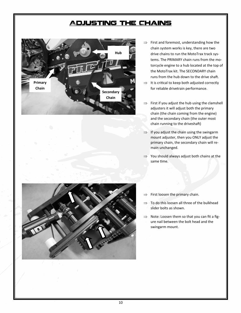
First and foremost, understanding how the
chain system works is key, there are two
drive chains to run the MotoTrax track sys-
tems. The PRIMARY chain runs from the mo-
torcycle engine to a hub located at the top of
the MotoTrax kit. The SECONDARY chain
runs from the hub down to the drive shaft.
It is critical to keep both adjusted correctly
for reliable drivetrain performance.
First if you adjust the hub using the clamshell
adjusters it will adjust both the primary
chain (the chain coming from the engine)
and the secondary chain (the outer most
chain running to the driveshaft)
If you adjust the chain using the swingarm
mount adjuster, then you ONLY adjust the
primary chain, the secondary chain will re-
main unchanged.
You should always adjust both chains at the
same time.
First loosen the primary chain.
To do this loosen all three of the bulkhead
slider bolts as shown.
Note: Loosen them so that you can fit a fig-
ure nail between the bolt head and the
swingarm mount.
Adjusting the Chains
Primary
Chain Secondary
Chain
Hub

11
Spin the adjuster bolt clockwise until the
adjuster bottoms out. Do not force it past
the point when it becomes difficult to turn.
This will loosen the primary chain.
Note: If the adjuster bolt binds up at all it
means that you did not loosen all of the slid-
er bolts properly.
Now loosen the drive hub
Once the drive hub is loose, again one finger
nail between bolt head and clamshell, use a
10mm Allen to spin the clamshell out until
the side chain is fully tightened. Note: Make
sure both clamshells are in the same config-
uration, you may need to count the number
of divots from fully rested to confirm this.
Note: Do not overtighten the size chain,
there should be at least. 1/8” of play when
pressing the center of the chain as shown.
Tighten the hub from the outside holding
the nut on the inside, this will ensure that
the clamshells do not spin during the tight-
ening process.
Torque: NM: 80.0 F/LBS: 59.0
12
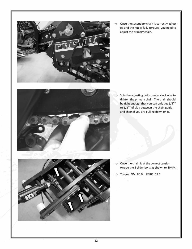
Once the secondary chain is correctly adjust-
ed and the hub is fully torqued, you need to
adjust the primary chain.
Spin the adjusting bolt counter clockwise to
tighten the primary chain. The chain should
be tight enough that you can only get 1/4””
to 1/2”” of play between the chain guide
and chain if you are pulling down on it.
Once the chain is at the correct tension
torque the 3 slider bolts as shown to 80NM.
Torque: NM: 80.0 F/LBS: 59.0
13
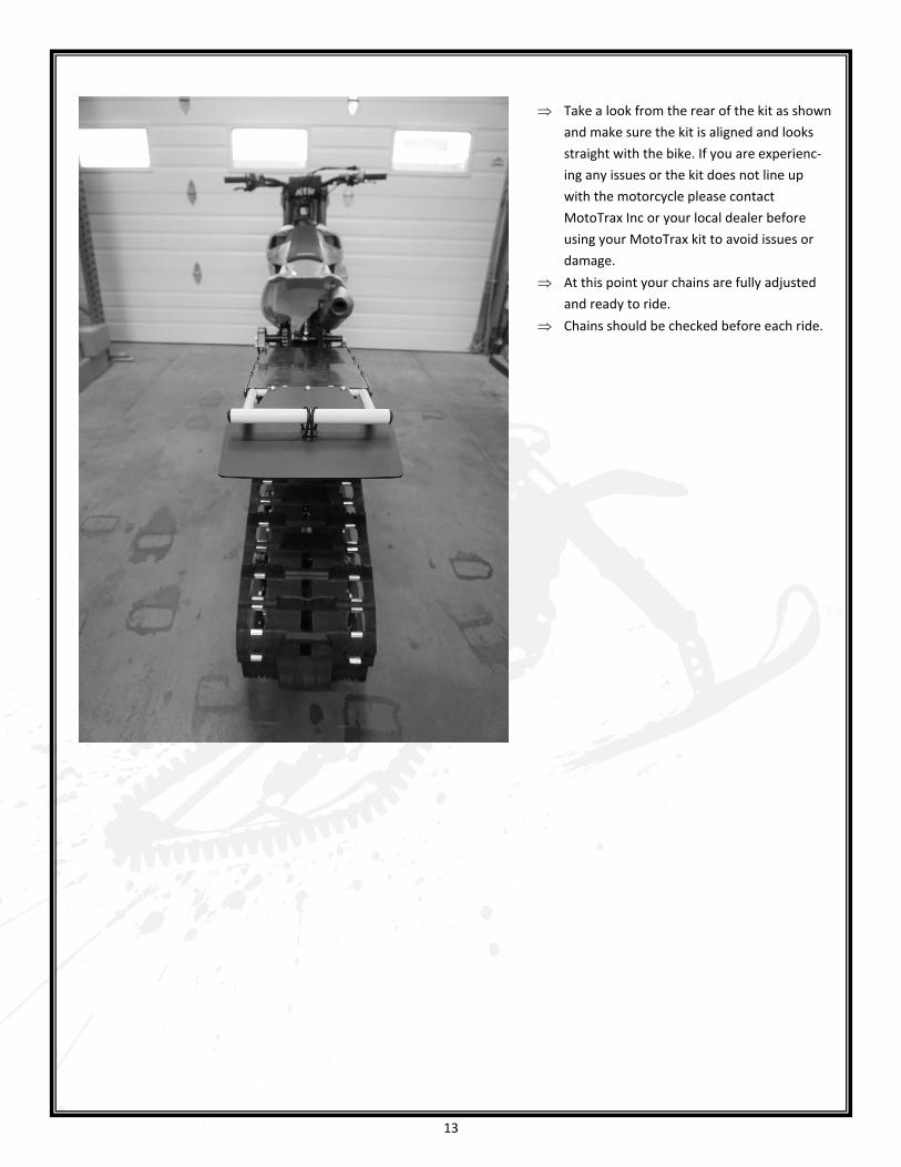
Take a look from the rear of the kit as shown
and make sure the kit is aligned and looks
straight with the bike. If you are experienc-
ing any issues or the kit does not line up
with the motorcycle please contact
MotoTrax Inc or your local dealer before
using your MotoTrax kit to avoid issues or
damage.
At this point your chains are fully adjusted
and ready to ride.
Chains should be checked before each ride.
14
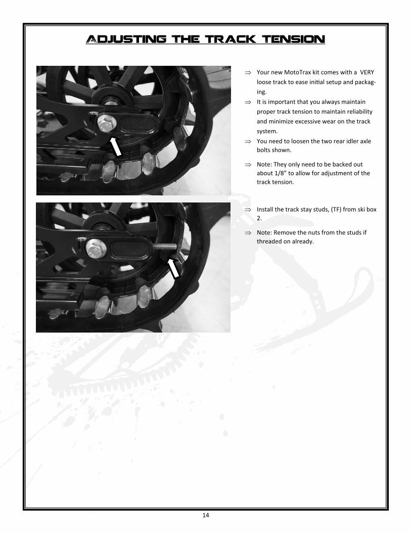
Your new MotoTrax kit comes with a VERY
loose track to ease initial setup and packag-
ing.
It is important that you always maintain
proper track tension to maintain reliability
and minimize excessive wear on the track
system.
You need to loosen the two rear idler axle
bolts shown.
Note: They only need to be backed out
about 1/8” to allow for adjustment of the
track tension.
Install the track stay studs, (TF) from ski box
2.
Note: Remove the nuts from the studs if
threaded on already.
Adjusting The track Tension
15
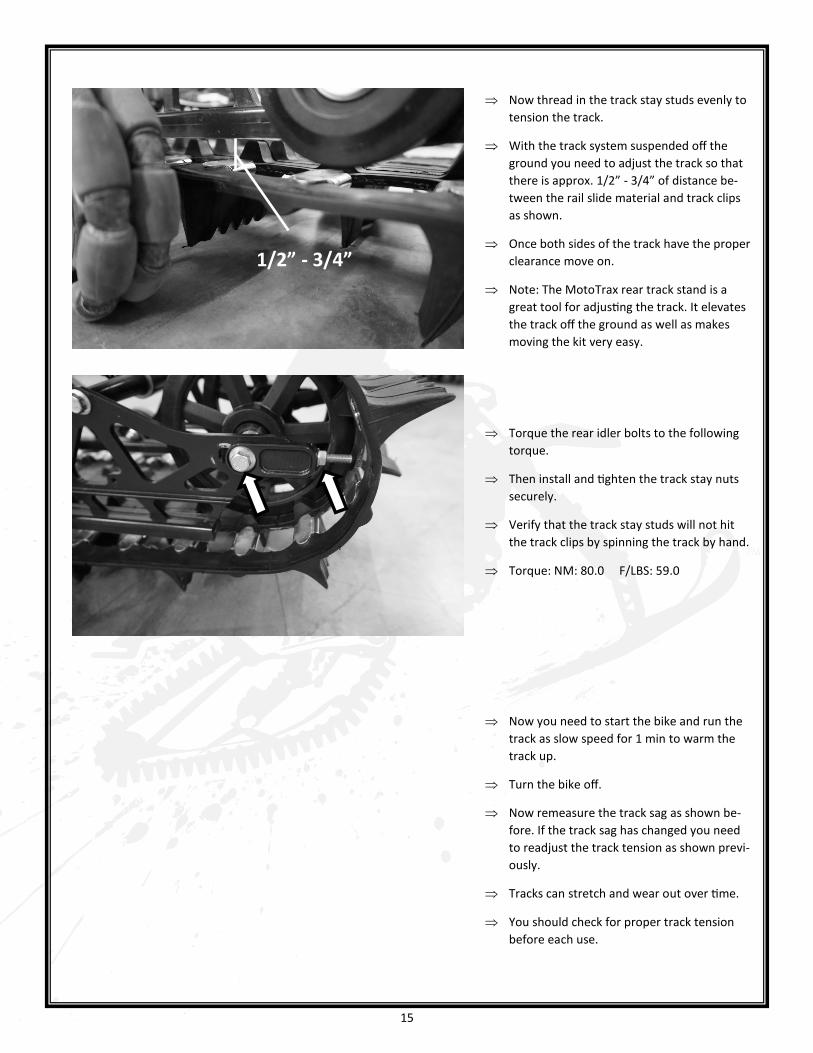
Now thread in the track stay studs evenly to
tension the track.
With the track system suspended off the
ground you need to adjust the track so that
there is approx. 1/2” - 3/4” of distance be-
tween the rail slide material and track clips
as shown.
Once both sides of the track have the proper
clearance move on.
Note: The MotoTrax rear track stand is a
great tool for adjusting the track. It elevates
the track off the ground as well as makes
moving the kit very easy.
Torque the rear idler bolts to the following
torque.
Then install and tighten the track stay nuts
securely.
Verify that the track stay studs will not hit
the track clips by spinning the track by hand.
Torque: NM: 80.0 F/LBS: 59.0
Now you need to start the bike and run the
track as slow speed for 1 min to warm the
track up.
Turn the bike off.
Now remeasure the track sag as shown be-
fore. If the track sag has changed you need
to readjust the track tension as shown previ-
ously.
Tracks can stretch and wear out over time.
You should check for proper track tension
before each use.
1/2” - 3/4”

16
On the Motocross model there is a FOX RC2 shock.
The shock is equipped with many forms of adjust-
ment.
Spring Preload – This is used to set ride height.
ONLY adjust spring preload for small amount of
ride height adjustment, if major adjustment is
needed you should install a different spring rate.
Turning the adjuster right increases the preload
Turning the adjuster left decreases the preload
High Speed Compression – This is used to adjust
the compression damping effect of high speed
impacts, note this is high shock shaft speed and
not necessarily high speed riding.
Turning the adjuster right increases the damping
Turning the adjuster left decreases the damping
Low Speed Compression – This is used to adjust
the compression damping effect of low speed
impacts, note this is low shock shaft speed and
not necessarily low speed riding.
Turning the adjuster right increases the damping
Turning the adjuster left decreases the damping
Adjusting the Shock Absorber
(MX Model)
Increase Damping
Decrease Damping
Increase Preload
Decrease Preload
17
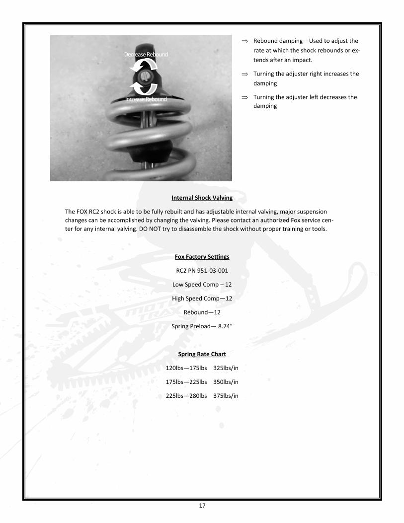
Rebound damping – Used to adjust the
rate at which the shock rebounds or ex-
tends after an impact.
Turning the adjuster right increases the
damping
Turning the adjuster left decreases the
damping
Internal Shock Valving
The FOX RC2 shock is able to be fully rebuilt and has adjustable internal valving, major suspension
changes can be accomplished by changing the valving. Please contact an authorized Fox service cen-
ter for any internal valving. DO NOT try to disassemble the shock without proper training or tools.
Fox Factory Settings
RC2 PN 951-03-001
Low Speed Comp – 12
High Speed Comp—12
Rebound—12
Spring Preload— 8.74”
Spring Rate Chart
120lbs—175lbs 325lbs/in
175lbs—225lbs 350lbs/in
225lbs—280lbs 375lbs/in
Decrease Rebound
Increase Rebound
18
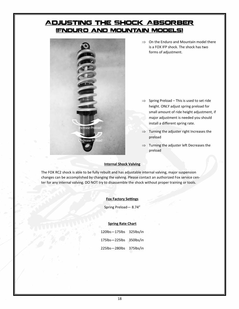
On the Enduro and Mountain model there
is a FOX IFP shock. The shock has two
forms of adjustment.
Spring Preload – This is used to set ride
height. ONLY adjust spring preload for
small amount of ride height adjustment, if
major adjustment is needed you should
install a different spring rate.
Turning the adjuster right Increases the
preload
Turning the adjuster left Decreases the
preload
Adjusting the Shock Absorber (Enduro and Mountain Models)
Internal Shock Valving
The FOX RC2 shock is able to be fully rebuilt and has adjustable internal valving, major suspension
changes can be accomplished by changing the valving. Please contact an authorized Fox service cen-
ter for any internal valving. DO NOT try to disassemble the shock without proper training or tools.
Fox Factory Settings
Spring Preload— 8.74”
Spring Rate Chart
120lbs—175lbs 325lbs/in
175lbs—225lbs 350lbs/in
225lbs—280lbs 375lbs/in
Increase Preload
Decrease Preload

19
Rail Slide Lock M5 Allen Torque NM: 7.0 F/LBS: 5.0 Red
Brake Rotor M6 Allen Torque NM: 9.0 F/LBS: 6.5 Red
Plastic Guards M6 Allen Torque NM: 5.0 F/LBS: 3.5 Red
Rail Cap M6 Hex Torque NM: 12.0 F/LBS: 9.0 NA
Brake Caliper Pin M8 Allen Torque NM: 20.0 F/LBS: 14.8 Red
Tunnel Cover M8 Allen Torque NM: 30.0 F/LBS: 22.0 NA
Snow Flap Bolt M8 Allen Torque NM: 30.0 F/LBS: 22.0 NA
Bearing Carrier M8 Allen Torque NM: 30.0 F/LBS: 22.0 Red
Banjo Bolt M10 Hex Torque NM: 30.0 F/LBS: 22.0 NA
Bulkhead/Tunnel M10 Hex Torque NM: 60.0 F/LBS: 44.0 Red
Rear Arm Upper M10 Hex Torque NM: 60.0 F/LBS: 44.0 Red
Rear Arm Lower M10 Hex Torque NM: 60.0 F/LBS: 44.0 Red
Skid Brace M10 Hex Torque NM: 60.0 F/LBS: 44.0 Red
Rear Slider M10 Hex Torque NM: 60.0 F/LBS: 44.0 Red
Shock Upper M10 Hex Torque NM: 60.0 F/LBS: 44.0 NA
Shock Lower M10 Hex Torque NM: 60.0 F/LBS: 44.0 Red
Driveshaft M10 Hex Torque NM: 60.0 F/LBS: 44.0 Red
Chain Case with Locknut M10 Hex Torque NM: 60.0 F/LBS: 44.0 NA
Chain Case to Bulkhead M10 Hex Torque NM: 60.0 F/LBS: 44.0 Red
Rail Pivot M12 Hex Torque NM: 80.0 F/LBS: 59.0 NA
Upper Swingarm M12 Hex Torque NM: 80.0 F/LBS: 59.0 Red
Upper Front Link M12 Hex Torque NM: 80.0 F/LBS: 59.0 Red
Mid Link Front/Back M12 Hex Torque NM: 80.0 F/LBS: 59.0 Red
Rear Idler Axle M12 Hex Torque NM: 80.0 F/LBS: 59.0 Blue
Hub Axle M12 Hex Torque NM: 80.0 F/LBS: 59.0 NA
Primary Chain Adjuster M12 Hex Torque NM: 80.0 F/LBS: 59.0 Blue
Track System Torque Values