2018 Kentucky Residential Code - dhbc.ky.govdhbc.ky.gov/Documents/2018 Kentucky Residential Code -...
50
2018 Kentucky Residential Code First Edition June 2018 As Adopted by: Department of Housing, Buildings and Construction 101 Sea Hero Road, Suite 100 Frankfort, Kentucky 40601-5412 Telephone: (502) 573-0365 FAX: (502) 573-1057 Telephone: (502) 573-0365 FAX: (502) 573-1057
Transcript of 2018 Kentucky Residential Code - dhbc.ky.govdhbc.ky.gov/Documents/2018 Kentucky Residential Code -...

2018 Kentucky
Residential Code
First Edition
June 2018
As Adopted by:
Department of Housing, Buildings and Construction
101 Sea Hero Road, Suite 100
Frankfort, Kentucky 40601-5412
Telephone: (502) 573-0365
FAX: (502) 573-1057
Telephone: (502) 573-0365 FAX: (502) 573-1057

ii
PREFACE
The Kentucky Residential Code (KRC) is essentially the 2015 International
Residential Code published by the International Code Council, Inc., with the
specific Kentucky amendments. It provides minimum standards to ensure the
public safety, health and welfare insofar as they are affected by building
construction, and to secure safety to life and property from all hazards incident to
the occupancy of buildings, structures, or premises. This edition presents the code
with changes approved by the Kentucky Department of Housing, Buildings and
Construction through April 2018.
The Kentucky Residential Code is a “mini/maxi” code, in that it establishes
minimum and maximum building code requirements for detached single-family
dwellings, two-family dwellings and townhouses and no local government shall
adopt or enforce any other building code on these units.
The Kentucky Residential Code may be amended from time to time by the
Department of Housing, Buildings and Construction through the regulatory process
by considering proposals from code enforcement officials, industry, and design
professionals, and other interested persons and organizations. Amendments are
discussed during open meetings of the Housing, Buildings and Construction
Advisory Committee. Approved amendments by the Department and the
Legislative Review Commission are printed in the Kentucky Administrative
Register and posted on the Department’s website (dhbc.ky.gov).
iii
SAMPLE ORDINANCE FOR ADOPTION OF THE
INTERNATIONAL
RESIDENTIAL CODE FOR
SINGLE FAMILY DWELLINGS
ORDINANCE NO.
An ordinance of the adopting the 2018 edition of the Kentucky Residential Code, regulating and
controlling the design, construction, quality of materials, erection, installation, alteration, repair, location, relocation,
replacement, addition to, use or maintenance of one- and two-family dwellings and townhouses in the ;
providing for the issuance of permits and collection of fees therefore when used with money; repealing Ordinance No. of the
and all other ordinances and parts of the ordinances in conflict therewith.
The of the does ordain as follows:
Section 1. That certain documents, three (3) copies of which are on file in the office of the KEEPER of RECORDS
and the , being marked and designated as Kentucky Residential Code, is hereby adopted as the code of the
for regulating the design, construction, quality of materials, erection, installation, alteration, repair, location,
relocation, replacement, addition to, use or maintenance of one- and two-family dwellings and townhouses not more than three
stories in height in the and providing for the issuance of permits and collection of fees therefore; and each and all of the
regulations, provisions, conditions and terms of such Kentucky Residential Code, 2018 edition, on file in the office of the
are hereby referred to, adopted and made a part hereof as if fully set out in this ordinance.
Section 2. The following sections are hereby revised:
Section R101.1 Insert: [NAME OF JURISDICTION]
Table R301.2(l) Insert: [APPROPRIATE DESIGN CRITERIA)
Section 3. That Ordinance No. of entitled (fill in here the complete title of the
present ordinance or ordinances in effect at the present time so that they will be repealed by definite mention) and all other
ordinances or parts of ordinances in conflict herewith are hereby repealed.
Section 4. That if any section, subsection, sentence, clause or phrase of this ordinance is, for any reason, held to be unconstitutional,
such decision shall not affect the validity of the remaining portions of this ordinance. The
- hereby declares that it would have passed this ordinance, and each section, subsection, clause or phrase thereof, irrespective of the
fact that any one or more sections, subsections, sentences, clauses and phrases be declared unconstitutional.
Section 5. That the [JURISDICTIOR'S—KEEPER OF RECORDS-] is hereby ordered and directed to cause this ordinance to
be published. (An additional provision may be required to direct the number of times the ordinance is to be published and to specify
that it is to be in a newspaper in general circulation. Posting may also be required.)
Section 6. That this ordinance and the rules, regulations, provisions, requirements, orders and matters established and adopted
hereby shall take effect and be in full force and effect from and after the date of its final passage and
adoption.

iv
TABLE OF CONTENTS
CHAPTER 1
SCOPE AND ADMINISTRATION .................................. 1
Section
R101 General .................................................................... 1
R102 Applicability ........................................................... 1
R103 Department of Building Safety ............................... 2
R104 Duties and Powers of Building Official .................. 2
R105 Permits .................................................................... 2
R106 Construction Documents ......................................... 3
R107 Temporary Structures and Uses .............................. 3
R108 Fees ......................................................................... 4
R109 Inspections .............................................................. 4
R110 Certificate of Occupancy ......................................... 4
R111 Service Utilities ....................................................... 4
R112 Appeals ................................................................... 5
R113 Violations ................................................................ 6
R114 Stop Work Order ..................................................... 6
R115 Proof of Insurance ................................................... 6
R116 Effective Dates ........................................................ 6
CHAPTER 2
DEFINITIONS .................................................................... 7
Section
R202 Definitions .............................................................. 7
CHAPTER 3
BUILDING PLANNING .................................................... 9
Section
R301 Design Criteria ........................................................ 9
R302 Fire-Resistant Construction ................................... 13
R307 Toilet, Bath and Shower Spaces ............................ 15
R310 Emergency Escape and Rescue Openings ............. 15
R311 Means of Egress .................................................... 15
R312 Guards and Window Fall Protection ..................... 16
R313 Automatic Fire Sprinkler Systems ........................ 17
R326 Swimming Pools, Spas and Hot Tubs ................... 17
R327 Post and Frame Structures ..................................... 18
R328 Tiny Houses .......................................................... 23
CHAPTER 4
FOUNDATIONS ............................................................... 25
Section
R401 General .................................................................. 25
R403 Footings ................................................................. 25
R404 Foundations and Retaining Walls ......................... 28
CHAPTER 5
FLOORS ............................................................................ 31
Section
R502 Wood Floor Framing ............................................. 31
R507 Exterior Decks....................................................... 31
CHAPTER 6
WALL CONSTRUCTION ............................................... 32
Section
R602 Wood Wall Framing ............................................. 32
CHAPTER 7
WALL COVERING ......................................................... 33
Section
R703 Exterior Covering ................................................. 33
CHAPTER 9
ROOF ASSEMBLIES ...................................................... 35
Section
R905 Requirements for Roof Coverings ........................ 35
CHAPTER 11
ENERGY EFFICIENCY
Section
N1101 General .................................................................... 36
CHAPTER 13
GENERAL MECHANICAL SYSTEMS
REQUIREMENTS
Section
M1301 General ................................................................... 38
M1305 Appliance Access ................................................... 38
CHAPTER 14
HEATING AND COOLING EQUIPMENT AND APPLIANCES ................................................................... 39
Section
M1403 Heat Pump Equipment ....................................... 39
M1411 Heating and Cooling Equipment ........................ 39
M1416 Mini-Split Heat Pumps ...................................... 39
CHAPTER 15
EXHAUST SYSTEMS ..................................................... 40
Section
M1502 Clothes Dryer Exhaust ....................................... 40
M1503 Range Hoods ...................................................... 40
CHAPTER 16
DUCT SYSTEMS ............................................................. 41
Section
M1601 Duct Construction .............................................. 41
CHAPTER 17
COMBUSTION AIR ........................................................ 42

v
CHAPTER 18
CHIMNEYS AND VENTS ............................................... 42
CHAPTER 19
SPECIAL APPLIANCES, EQUIPMENT AND
SYSTEMS .......................................................................... 42
CHAPTER 20
BOILERS AND WATER HEATERS ............................. 42
CHAPTER 24
FUEL GAS ......................................................................... 42
CHAPTER 25
PLUMBING ADMINISTRATION ................................. 42
CHAPTER 26
GENERAL PLUMBING REQUIREMENTS ................ 42
CHAPTER 27
PLUMBING FIXTURES .................................................. 42
CHAPTER 28
WATER HEATERS ......................................................... 42
CHAPTER 29
WATER SUPPLY AND DISTRIBUTION ..................... 42
CHAPTER 30
SANITARY DRAINAGE ................................................. 42
CHAPTER 31
VENTS ............................................................................... 42
CHAPTER 32
TRAPS ............................................................................... 43
CHAPTER 33
STORM DRAINS .............................................................. 43
CHAPTER 34
GENERAL REQUIIREMENTS ..................................... 43
CHAPTER 35
ELECTRICAL DEFINITIONS....................................... 43
CHAPTER 36
SERVICES ........................................................................ 43
CHAPTER 37
BRANCH CIRCUIT AND FEEDER REQUIREMENTS
............................................................................................ 43
CHAPTER 38
WIRING METHODS ....................................................... 43
CHAPTER 39
POWER AND LIGHTING DISTRIBUTION ................ 43
CHAPTER 40
DEVICES AND LUMINARIES ...................................... 43
CHAPTER 41
APPLIANCE INSTALLATION ..................................... 43
CHAPTER 42
SWIMMING POOLS ....................................................... 43
CHAPTER 43
CLASS 2 REMOTE-CONTROL, SIGNALING AND POWER-LIMITED CIRCUITS ...................................... 43
CHAPTER 44
REFERENCED STANDARDS ....................................... 44

CHAPTER 1
ADMINISTRATION
SECTION R101
GENERAL
R101.1 Title. These provisions shall be known as the
Kentucky Residential Code for One- and Two-family
Dwellings and shall be cited as such and will be referred to
herein as "this code.”
R101.2 Scope. The provisions of the Kentucky Residential
Code for One- and Two-family Dwellings shall apply to the
construction, alteration, movement, enlargement,
replacement, repair, equipment, use and occupancy, location,
removal and demolition of detached one- and two-family
dwellings and townhouses not more than three stories above
grade plane in height with a separate means of egress and
their accessory structures
Exceptions:
1. Live/work units complying with the requirements of
Section 419 of the Kentucky Building Code shall be
permitted to be built as one- and two-family dwellings or
townhouses. Fire suppression required by Section 419.5
of the Kentucky Building Code when constructed under
the International Residential Code for One- and Two-
family Dwellings shall conform to Section P2904.
2. Owner-occupied lodging houses with five or fewer
guestrooms shall be permitted to be constructed in
accordance with the Kentucky Residential Code for One-
and Two-family Dwellings when equipped with a fire
sprinkler system in accordance with Section P2904.
3. Farm dwellings and other buildings and structures
located on farms which are incident to the operation of
the farm and located outside the boundary of a
municipality; but only if they are not used in the business
of retail trade, as a regular place of work for 10 or more
people or for the processing or storage of timber
products.
4. Manufactured homes constructed under federal HUD
standards. However, the exterior electric, water and
sewer connections and additions to the home are not
exempt.
5. Swimming pools constructed completely above grade.
R101.3 Intent. The purpose of this code is to establish
minimum and maximum requirements to safeguard the public
safety, health and general welfare through affordability,
structural strength, means of egress facilities, stability,
sanitation, light and ventilation, energy conservation and
safety to life and property from fire and other hazards
attributed to the built environment and to provide safety to fire
fighters and emergency responders during emergency
operations. No local government shall adopt or enforce any
other building code for detached single family dwellings, two-
family dwellings and townhouses.
R101.4 Other residential buildings. Multiple single-family
dwellings (townhouses) over three stories above grade in
height or without separate entrances shall comply with the
Kentucky Building Code (KBC).
R101.5 Accepted practices. In the absence of provisions not
specifically contained in this code or final decisions of the
appeals board, the specification and standards listed in
Chapter 44 shall be deemed to represent accepted engineering
practice with respect to materials, equipment, systems or
method of construction as specified and shall be acceptable.
R101.6 Licensed HVAC contractors. All work involving
HVAC as defined and required by KRS Chapter 198B shall
be provided by a licensed Journeyman HVAC Mechanic
working under the supervision of a licensed Master HVAC
Contractor. The building official will require proof of
licensure when making inspections.
R101.7 Plumbing contractors and inspections. All
plumbing installations shall be performed under the
supervision of a Kentucky Licensed Master Plumber
according to law and shall be inspected and approved by the
state plumbing inspector prior to usage pursuant to KRS
Chapter 318 and 815 KAR Chapter 20. The building official
will require proof of licensure when making inspections.
R101.8 Electrical contractors and inspections. All
electrical installations shall be performed by licensed
electricians according to law and shall be inspected by a
certified electrical inspector pursuant to KRS 227.489 and
KAR 35:015. The building official will require proof of
licensure when making inspections.
SECTION R102
APPLICABILITY
R102.2 Other laws. The provisions of this code shall not be
deemed to nullify any provisions of local, state or federal law.
Other local, state or federal law shall be consulted to
determine the existence of other powers given to the code
official, such as those related to demolition or authority over
unsafe structures; however, no local ordinance shall establish
any additional or contradictory building construction standard
than those adopted in this code.
R102.5 Appendices. Provisions in the appendices of the 2016
Kentucky Residential Code shall not apply unless specifically
referenced in the adopting ordinance.
R102.5.1 Appendix K, Sound transmission. The
provisions found in Appendix K shall apply to wall and
floor-ceiling assemblies separating dwelling units
including those separating townhouses.
R102.5.2 Appendix R, Light Straw-Clay Construction. The provisions found in Appendix R shall apply to light
1
2
straw clay construction as a nonbearing building material
and wall infill systems.
R102.5.3 Appendix S, Strawbale Construction. The
provisions found in Appendix S provides prescriptive and
performance-based requirements for the use of baled straw
as a building material.
R102.7 Existing structures. The legal occupancy of any
structure existing on the date of adoption of this code shall
be permitted to continue without change, except as is
specifically covered in this code, the locally adopted
property maintenance code, or as is deemed necessary by the
building official for the general safety and welfare of the
occupants and the public.
R102.8 Plumbing. The provisions of the Kentucky State
Plumbing Code shall apply to the installation, alteration,
repair and replacement of plumbing systems, including
equipment, appliances, fixtures, fittings and appurtenances.
R102.9. Electrical. The electrical system shall be installed in
compliance with NFPA 70 as adopted by the Commonwealth
of Kentucky.
SECTION R103
DEPARTMENT OF BUILDING SAFETY
R103.2.1 Certified inspectors. The local government shall
provide at least one Kentucky Certified Building Inspector,
Level I, pursuant to 815 KAR 7:070, and certified electrical
inspector, certified according to 815 KAR 35:015. The
local government shall report the name of all inspectors to
the Department and the Department shall be notified of any
changes in inspection personnel. To enforce the residential
code only, the local government shall provide at least one
inspector that has achieved 1 & 2 Family Dwelling
Certification.
R103.3 Deputies. In accordance with the prescribed
procedures of this jurisdiction and with the concurrence of the
appointing authority, the building official shall have the
authority to appoint a deputy building official, the related
technical officers, inspector, plan examiners and other
employees. Such employees shall have powers as delegated
by the building official. These appointments shall meet the
requirements of 815 KAR 7:070 for certification associated
with their job duties.
SECTION R104
DUTIES AND POWERS OF THE BUILDING
OFFICIAL
R104.7 Department records. The building official shall
keep official records of applications received, permits and
certificates issued, fees collected, reports of inspections,
and notices and orders issued. Such records shall be
retained in the official records for the period required for
the retention of public records as promulgated by the
Kentucky Department of Libraries and Archives pursuant
to KRS 171.450.
R104.10.1 Flood hazard areas. The building official
shall not grant modifications to any provision related to
flood hazard areas as established by local jurisdiction
without the granting of a variance to such provisions by
the board of appeals.
SECTION R105
PERMITS
R105.2 Work exempt from permit. Exemption from permit
requirements of this code shall not be deemed to grant
authorization for any work to be done in any manner in
violation of the provisions of this code or any other laws or
ordinances of this jurisdiction. Permits shall not be required
for the following:
Building:
1. One-story detached accessory structures used as tool and
storage sheds, playhouses and similar uses, provided the
floor area does not exceed 200 square feet (18.58 m2).
2. Fences not over 7 feet (1829 mm) high.
3. Retaining walls that are not over 4 feet (1219 mm) in
height measured from grade at the bottom of the wall to
the top of the wall.
4. Water tanks supported directly upon grade if the capacity
does not exceed 5000 gallons (18927L) and the ratio of
height to diameter or width does not exceed 2 to 1.
5. Sidewalks and driveways.
6. Painting, papering, tiling, carpeting, cabinets, counter
tops and similar finish work.
7. Swings and other playground equipment.
8. Window awnings supported by an exterior wall which do
not project more than 54 inches (1372 mm) from the
exterior wall and do not require additional support.
9. Decks not exceeding 200 square feet (18.58 m2) in area,
that are not more than 30 inches (762mm) above grade at
any point, are not attached to a dwelling and do not serve
the exit door require by Section R311.4.
Electrical:
1. Listed cord-and-plug connected temporary decorative
lighting.
2. Reinstallation of attachment plug receptacles but not the
outlets therefor.
3. Replacement of branch circuit overcurrent devises of the
required capacity in the same location.
4. Electrical wiring, devices, appliances, apparatus or
equipment operations at less than 25 volts and not
capable of supplying more than 50 watts of energy.
5. Minor repair work, including the replacement of lamps
or the connection of approved portable electrical
equipment to approved permanently installed
receptacles. 6. The provisions of this code shall not apply to electrical
equipment used for radio and television transmissions.

3
7. The installation of any temporary system required for the
testing or servicing of electrical equipment or apparatus.
Gas:
1. Portable heating appliance.
2. Replacement of any minor part that does not alter ap-
proval of equipment or make such equipment unsafe. 3. Portable-fuel-cell appliances that are not connected to a
fixed piping system and are not interconnected to a power grid.
Mechanical:
1. Portable heating appliance;
2. Portable ventilation equipment;
3. Portable cooling unit;
4. Steam, hot or chilled water piping within any heating or
cooling equipment regulated by this code.
5. Replacement of any part which does not alter its approval
or make it unsafe.
6. Portable evaporative cooler;
7. Self-contained refrigeration system containing 10 pounds
(4.54 kg) or less of refrigerant and actuated by motors of
1 horsepower (746 W) or less.
8. Portable-fuel-cell appliances that are not connected to a
fixed piping system and are not interconnected to a power
grid.
Plumbing
1. The stopping of leaks in drains, water, soil, waste or vent
pipe; provided, however, that if any concealed trap,
drainpipe, water, soil, waste or vent pipe becomes
defective and it becomes necessary to remove and replace
the same with new material, such work shall be
considered as new work and a permit shall be obtained
and inspection made as provided in this code.
2. The clearing of stoppages or the repairing of leaks in
pipes, valves or fixtures, and the removal and
reinstallation of water closets, provided such repairs do
not involve or require the replacement or rearrangement
of valves, pipes or fixtures.
R105.3 Application for permit. To obtain a permit, the
applicant shall first file an application in writing on a form
furnished for that purpose by the department of building
safety. Such application shall:
1. Identify and describe the work to be covered by the
permit for which application is made.
2. Describe the land on which the proposed work is to be
done by legal description, street address or similar
description that will readily identify and definitely
locate the proposed building or work. New building or
additions shall be accompanied by a copy of the current
site survey bearing the seal and of a Kentucky
Registered Land Surveyor, except the building official
may, at the building official’s discretion, accept other
proof of location.
3. Indicate the use and occupancy for which the proposed
work is intended.
4. Be accompanied by construction documents and other
information as required by Section 106.1.
5. Give such other data and information as required by the
building official.
SECTION R106
CONSTRUCTION DOCUMENTS
R106.1 Submittal documents. Submittal documents
consisting of construction documents, and other data shall be
submitted in two or more sets with each application for a
permit. Where special conditions exist, the building official is
authorized to require additional construction documents to be
prepared by a licensed design professional.
Exception: The building official is authorized to waive the
submission of construction documents and other data not
required to be prepared by a licensed design professional if
it is found that the nature of the work applied for is such
that reviewing of construction documents is not necessary
to obtain compliance with this code.
R106.1.3 Information on construction in flood hazard
areas. For buildings and structures located in whole or in
part in flood hazard areas as established by local jurisdiction or floodplain manager floor construction
documents shall include:
1. Delineation of flood hazard areas, floodway
boundaries and flood zones and the design flood
elevation, as appropriate.
2. The elevation of the proposed lowest floor, including
basement; in areas of shallow flooding (AO zones), the
height of the proposed lowest floor, including
basement, above the highest adjacent grade; and
3. The elevation of the bottom of the lowest horizontal
structural member in coastal high hazard areas (V
zone); and
4. If design flood elevations are not included on the
community’s Flood Insurance Rate Map (FIRM), the
building official and the applicant shall obtain and
reasonably utilize any design flood elevation and
floodway data available from other sources.
R106.2 Site plan or plot plan. The construction documents
submitted with the application for permit shall be
accompanied by a site plan showing the size and location of
new construction and existing structures on the site and
distances from lot lines, the established street grades and the
proposed finished grades; and it shall be drawn in accordance
with an accurate boundary line survey. In the case of
demolition, the site plan shall show construction to be
demolished and the location and size of existing structures
and construction that are to remain on the site or plot. The
building official is authorized to waive or modify the
requirement for a site plan when the application for permit is
for alteration or repair or when otherwise warranted.
106.5 Retention of construction documents. The building
official, as required by the Kentucky Department of Libraries
and Archives administrative regulations, shall retain approved
construction documents.

4
SECTION R107
TEMPORARY STRUCTURES AND USES
R107.3 Temporary power. The building official and/or the
applicable licensed and certified inspector listed in Section
101.8 are authorized to give permission to temporarily supply
and use power in part of an electric installation before such
installation has been fully completed and the final certificate
of completion has been issued. The part covered by the
temporary certificate shall comply with the requirements
specified for temporary lighting, heat or power in NFPA 70.
SECTION R108
FEES
R108.6 Work commencing before permit issuance. Any
person who commences any work on a building, structure,
electrical, gas, mechanical or plumbing system before
obtaining the necessary permits may be subject to penalties
established in KRS Chapters 198B, 227, 227A, 234, 236 and
318. The fee shall be in addition to and equal to the amount
of the original fee.
R108.7 Accounting. The building official shall keep an
accurate account of all fees collected and such collected fees
shall be deposited monthly in the jurisdiction treasury, or
otherwise disposed of as required by law.
SECTION R109
INSPECTIONS
R109.1 Types of inspections. For onsite construction, from
time to time the building official, upon notification from the
permit holder or his agent, shall make or cause to be made any
necessary inspections and shall either approve that portion of
the construction as completed or shall notify the permit holder
or his or her agent wherein the same fails to comply with this
code. Approval as a result of an inspection shall not be
construed to be an approval of a violation of the provisions of
this code or of other ordinances of the jurisdiction. Inspections
presuming to give authority to violate or cancel the provisions
of this code or of other ordinances of the jurisdiction shall not
be valid. It shall be the duty of the permit applicant to cause the
work to remain accessible and exposed for inspection
purposes. Neither the building official nor the jurisdiction
shall be liable for expense entailed in the removal or
replacement of any material required to allow inspection.
R109.1.3 Floodplain inspections. For construction in areas
prone to flooding as established by local jurisdiction, upon
placement of the lowest floor, including basement, and
prior to further vertical construction, the building official
shall require submission of documentation, prepared and
sealed by a registered design professional, of the elevation
of the lowest floor, including basement, required in Section
R322.
R109.1.6 Final inspections. Upon completion of the
building, the owner or agent of the facility shall request a
final inspection. The building official shall set a time for the
inspection and notify the owner or agent. If substantial
compliance with the approved construction documents and
permit has been achieved, a certificate of occupancy shall
be issued, as described in Section R110. If compliance has
not been achieved, violations of the approved construction
documents and permit shall be noted and immediately
communicated to the owner, agency and other person
holding the permit. It shall be the owner’s responsibility
and the responsibility of the person responsible for the
construction work to fulfill any compliance deficiencies
noted.
R109.1.7 Industrialized building system inspections.
The inspection of all buildings classified as industrialized
building systems, regardless of size or occupancy
classification, shall be in accordance with this section.
R109.1.7.1 Off-site construction. In-plant inspections in
production and manufacturing facilities for industrialized
building systems shall be conducted by the Department
or its authorized agent.
R109.1.7.2 On-site construction. On-site construction
related to modular homes or one- and two-family
dwelling installations may be permitted and inspected by
the local building official having jurisdiction upon notice
from the Department of an approved modular home. The
local code official having jurisdiction shall be
responsible for inspection of the foundation system,
placement of the building, connection of the units, final
set-up of the units and issuance of the certificate of
occupancy. The local building official shall be
responsible for inspection of these systems for zoning,
water supply and sewage disposal, and other applicable
local ordinance purposes.
SECTION R110
CERTIFICATE OF OCCUPANCY
R110.2 Change in use. Changes in the character or use of an
existing structure shall not be made except as specified in
Sections 3408 and 3409 of the Kentucky Building Code.
SECTION R111
SERVICE UTILITIES
R111.1 Connection of service utilities. No person shall make
connections from a utility, source of energy, fuel or power to
any building or system that is regulated by this code for which
a permit is required, until approved by the building official
and/or the applicable licensed and certified inspector listed in
sections R101.6, R101.7 and R101.8.
R111.2 Temporary connection. The building official and/or
the applicable licensed and certified inspector listed in

5
section R101.6, R101.7 and R101.8 shall have the authority to
authorize and approve the temporary connection of the
building or system to the utility, source of energy, fuel or
power.
R111.3 Authority to disconnect service utilities. The
building official and/or the applicable licensed and certified
inspector listed in section R101.6, R101.7 and R101.8 shall
have the authority to authorize disconnection of utility service
to the building, structure or system regulated by this code and
the referenced codes and standards set forth in Section R102.4
in case of emergency where necessary to eliminate an
immediate hazard to life or property or when such utility
connection has been made without the approval required by
Section R111.1 or R111.2. The building official shall notify
the serving utility and whenever possible the owner and
occupant of the building, structure or service system of the
decision to disconnect prior to taking such action if not
notified prior to disconnection. The owner or occupant of the
building, structure or service system shall be notified in
writing as soon as practical thereafter.
SECTION R112
APPEALS
R112.1 General. All appeals from the decisions of code
officials shall be conducted in accordance with the appeals
provisions of KRS 198B.070. Where a local appeals board
exists, a party must first appeal to the local board when
aggrieved by a decision of the local code official. The
Department shall further hear appeals directly from a party
aggrieved by the decision of an agent of the Department.
R112.2 Appeal by fire code official. Decisions rendered by
the code official with respect to enforcement of the Kentucky
Building Code on any building may be appealed by the local
fire code official of the jurisdiction if the fire code official is
aggrieved by that decision.
R112.3 Local appeals board. Local appeals boards may be
appointed to hear appeals from the decisions of the local code
official in accordance with the provisions of Sections 112.3.1
through 112.3.4.
R112.3.1 Appointment. The mayor or county judge
executive of a local government which is enforcing the
Kentucky Building Code may, upon approval of the local
legislative body, appoint a local appeals board, consisting
of at least five technically qualified persons with
professional experience related to the building industry,
three of which shall not be employees of the local
government, to hear appeals from the decisions of the local
code official regarding building code requirements.
R112.3.2 Cooperative agreements. Local governments
which are enforcing the Kentucky Building Code may
cooperate with each other and provide a local appeals board
and shall adhere to the provisions of KRS Chapter 65 when
entering into a cooperative agreement.
R112.3.3 Disqualification of member. Local code
officials or employees of a local inspection department
shall not sit on a local appeals board if the board is hearing
an appeal to a decision rendered by the local department. A
member of a local appeals board shall not hear an appeal in
a case in which the member has a financial interest.
R112.3.4 Right to appeal. Any party to a decision by the
local code official may appeal that decision to the local
appeals board. Upon receipt of an appeal from a qualified
party, the local appeals board shall convene a hearing to
consider the appeal within 15 days of receipt.
R112.3.5 Notice of meeting. All parties to the appeal shall
be notified of the time and place of the hearing by letter sent
by certified mail not later than 10 days prior to the date of
the hearing.
R112.3.6 Board decision. The local appeals board shall
render a decision within five working days after the
hearing. The board may uphold, amend or reverse the
decision of the local code official, and there shall be no
appeal from the decision of the local appeals board other
than by appeal to the Department.
R112.3.7 Open hearing. All hearings before the local
appeals board shall be open to the public. The appellant, the
appellant’s representative, the code official and any all
persons whose interests are affected shall be given an
opportunity to be heard.
R112.3.7.1 Procedure. The local appeals board shall
adopt and make available to the public through the
secretary procedures under which a hearing will be
conducted. The procedures shall not require compliance
with strict rules of evidence but shall mandate that only
relevant information be received.
R112.3.8 Board decision. The local appeals board shall
modify or reverse the decision of the code official by a
concurring vote of three members.
R112.4 Appeals to the State. Application for appeal by a
property owner may be made when it is claimed in writing
that the true intent of this code or the rules legally adopted
thereunder have been incorrectly interpreted, the provisions
of this code do not fully apply, or an equally good or better
form of construction can be used, or that the code official has
refused to grant a modification to the provisions of this code
covering the manner of construction or material to be used in
the erection, alteration or repair of a building or structure.
R112.4.1 Application procedure. Appeals to the
Department shall be in writing and shall be addressed to the
Commissioner of the Department of Housing, Buildings
and Construction, 101 Sea Hero Road, Suite 100, Frankfort,
Kentucky 40601-5412; Attention: Appeals. The appeal
shall include citations of those provisions of the Kentucky
Building Code that are at issue, an explanation of why the
decision of the state code official or local code official
6
relative to those provisions is being contested and a copy of
the decision rendered by the local appeals board, if any.
R112.4.2 Investigation of appeal. The Commissioner
shall immediately notify the Department or the five-
member committee authorized by the Commissioner when
an appeal is received. The Commissioner or a designated
employee of the Department shall then investigate the
evidence pertaining to the appeal and, based on the results
of the investigation, make written recommendations to the
Department or committee on the disposition of the case in
question, within 30 days.
R112.4.3 Employee deferral. Employees of the
Department shall not investigate or make recommendations
on an appeal to his or her decision, but shall defer in this
case to employees who are not party to the decision which
led to the appeal.
R112.4.4 Investigative authority. In conducting an
investigation, the Commissioner or the designated
representatives, acting for the Department, shall have the
authority to administer oaths and affirmations, issue
subpoenas authorized by law, rule upon offers of proof and
receive relevant evidence, take or cause depositions to be
taken, regulate the course of any hearings they may
schedule, and hold conferences for the settlement or
simplification of the issue by consent of the parties.
R112.4.5 Administrative hearing. Pursuant to KRS
Chapter 13B, if the issue has not been settled by agreement
of the parties within limitations set by Section 112.4.2, the
Department shall schedule an administrative hearing on the
matter. The cost of any appeal forwarded to the Department
because there is no local appeals board shall be borne by
the local government. The Department shall calculate the
actual cost of processing the appeal and bill the local
government at the conclusion of all proceedings.
112.4.6 Judicial appeals. Final orders of the Department
are appealable to the Circuit Court in the county in which
the property is located.
SECTION R113
VIOLATIONS
R113.4 Violation penalties. Any person who violates a
provision of this code or fails to comply with any of the
requirements thereof or who erects, constructs, alters or
repairs a building or structure in violation of the approved
construction documents or directive of the building official,
or of a permit or certificate issued under the provisions of this
code, shall be subject to penalties provided by KRS 198B.990
and other applicable law.
SECTION R114
STOP WORK ORDER
R114.4 Limitation on changes. No inspector shall be
authorized to require changes on-site that are contrary to the
approved construction documents. If an inspector finds a code
discrepancy in an on-site inspection, the inspector shall refer
the matter to the official having construction document
review responsibility who shall require corrections if the code
so requires.
SECTION R115
PROOF OF INSURANCE
R115.1 Compliance with law. The issuance of a building
permit shall be contingent upon presentation of proof to the
effect that all contractors and subcontractors employed or that
will be employed in the construction, alteration or repair
under the permit are in compliance with the Kentucky law
relating to worker’s compensation and unemployment
insurance.
R115.2 General applicability. Compliance with this section
shall be achieved by presenting certificates or other forms ap-
proved by the Kentucky Labor Cabinet to the code official
issuing the permit.
SECTION R116
EFFECTIVE DATES
R116.1 General. The building official shall accept plans
in compliance with the requirements of either the 2013
edition or the 2018 edition of the Kentucky Residential
Code. Effective January 1, 2019, this code shall be
mandatory and no permit shall be issued for construction
under any other building code.

7
SECTION R202
DEFINITIONS
CHAPTER 2
DEFINITIONS
INDUSTRIALIZED BUILDING SYSTEM or BUILDING
SYSTEM. Is defined by KRS 198B.010 (16) and means any
R202 DEFINITIONS. Section R202 Definitions of Habitable
Space and Historical Building of the 2015 IRC shall be
DELETED in their entirety.
BUILDING. is defined by KRS 198B.010(4) and " means any
combination of materials, whether portable or fixed, which
comprises a structure or non-mine underground area affording
facilities or shelter for any human occupancy, whether
infrequent or regular, and also means single-family dwellings,
including those sold or constructed under a trade or brand
name. The word "building" shall be construed wherever used
herein as if followed by the words "or part or parts thereof and
all equipment therein" unless the context clearly requires a
different meaning. "Building" shall also mean swimming pools
constructed below grade on site, but not swimming pools
assembled above grade on site. "Building" shall not mean a
manufactured home governed by the National Manufactured
Housing Construction and Safety Standards Act of 1974, 42
U.S.C. secs. 5401 et seq., or a farm dwelling or other farm
buildings and structures incident to the operation and
maintenance of the farm if the farm structures are located
outside the boundary of a municipality and are not used in the
business of retail trade or used as a place of regular
employment for ten (10) or more people or structures used in
the storage or processing of timber products.
BARRIER. A fence, a wall, a building wall, or combination
thereof, which completely surrounds the swimming pool and
obstructs access to the swimming pool.
COLLAR BEAM/TIE. A horizontal framing member
connecting opposing rafter elements for stability.
COMMISSIONER. Defined by KRS 198B.010 (9) and
means the commissioner of the Department of Housing,
Buildings and Construction.
DEPARTMENT. means the Department of Housing,
Buildings and Construction.
EGRESS ROOF ACCESS WINDOW. A skylight
or roof window designed and installed to satisfy the
emergency escape and rescue opening requirements
in Section R310.2.
FARM. Means property having a bona fide agricultural or
horticultural use as defined by KRS 132.010(9) and (10) which
is qualified by and registered with the property valuation
administrator in the county in which the property is located.
HOT TUB. See definition of private swimming pool.
structure or component thereof which is wholly or in
substantial part fabricated in an off-site manufacturing facility
for installation or assembly on a permanent foundation at the
building site.
IN-GROUND POOL. See definition of private swimming
pool.
KNEE WALL. Any short wall used as a part of the support
for a roof structure.
KRS. means the Kentucky Revised Statutes.
LANDING PLATFORM. A landing measuring two
treads deep and two risers tall, provided as the top step
of a stairway accessing a loft.
LOFT. Any floor level located above the main floor
and open to it on at least one side, with a ceiling height
less than 6 feet 8 inches (2032 mm), complying with
the area, access, and guard requirements of Section
AV104, and used as a living or sleeping space.
MANUFACTURED HOME. is defined by KRS 198B.010
(23) and 227.550 and means a single-family residential
dwelling constructed in accordance with the federal act,
manufactured after June 15, 1976, and designed to be used as
a single-family residential dwelling with or without a
permanent foundation when connected to the required utilities,
and includes the plumbing, heating, air conditioning, and
electrical systems contained therein. The manufactured home
may also be used as a place of business, profession, or trade by
the owner, the lessee, or the assigns of the owner or lessee and
may comprise an integral unit or condominium structure.
Buildings the construction of which is not preempted by the
federal act are subject to building code requirements of KRS
Chapter 198B.
MODULAR HOME. means an industrialized building system
which is designed to be used as a residence and which is not a
manufactured or mobile home.
ORDINARY REPAIR. is defined by KRS 198B.010 (19) and
means any nonstructural reconstruction or renewal of any part
of an existing building for the purpose of its maintenance, or
decoration, and shall include but not be limited to the
replacement or installation of nonstructural components of the
building such as roofing, siding, windows, storm windows,
insulation, drywall or lath and plaster, or any other
replacement, in kind, that does not alter the structural integrity,

8
alter the occupancy or use of the building, or affect, by
rearrangement, exitways and means of egress; but shall not
include additions to, or alteration of, or relocation of any
standpipe, water supply, sewer, drainage, gas, soil, waste, vent
or similar piping, electric wiring, or mechanical equipment
including furnaces and hot water heaters or other work
affecting public health or safety.
PERPENDICULAR LUMBER SHEATHING. For the
purposes of this code, any lumber sheathing, either spaced or
laid side-by-side having an angle of intersection with the rafter
or joist of 60 degrees or greater.
PRIVATE SWIMMING POOL. Any structure that contains
water over 24 inches (610 mm) deep and which:
a. is used, or intended to be used, for swimming or
recreational bathing in connection with a Group R-3
occupancy; and
b. is available only to the family and guests of the
householder. This includes swimming pools
constructed below grade on site, but not those
assembled above grade on site.
PRIVATE SWIMMING POOL, OUTDOOR. Any private
swimming pool that is not an indoor pool.
RATIONAL ANALYSIS. Alternative analytical calculations,
experimental data, published design data or other referenced
citations that have been approved for use by the building
official.
REPAIR. The reconstruction or renewal of any part of an
existing building for the purpose of its maintenance. See also
“ordinary repair.”
SPA. See definition of private swimming pool.
SWIMMING POOL. Any structure intended for swimming,
recreational bathing or wading that contains water over 24
inches (610 mm) deep. This includes in-ground, pools,
hot tubs, spas and fixed-in-place wading pools.
TINY HOUSE. A dwelling which is 400 or less
square feet (37 m2) in floor area excluding lofts.

9
CHAPTER 3
BUILDING PLANNING
SECTION R301
DESIGN CRITERIA
R301.1.1 Alternative provisions. As an alternative to the
requirements in Section R301.1, the following standards are
permitted subject to the limitations of this code and the
limitations therein. Where engineered design is used in
conjunction with these standards the design shall comply
with the Kentucky Building Code.
1. American Forest and Paper Association (AF&PA)
Wood Frame Construction Manual (WFCM).
2. American Iron and Steel Institute (AISI) Standard for
Cold-Formed Steel Framing – Prescriptive Method for
One-and Two-Family Dwellings (COFS/PM) with
Supplement to Standard for Cold-Formed Steel Framing
– Prescriptive Method for One-and Two-Family
Dwellings.
3. ICC Standard on the Design and Construction of Log
Structures (ICC 400).
4. Federal Emergency Management Administration,
Homebuilders’ Guide to Earthquake Resistant
Construction, FEMA 232-June 2006.
5. American Wood Council Prescriptive Residential Wood
Deck Construction Guide (DCA6).
6. National Frame Builders Association Post Frame
Building Design Manual.
R301.2 Climatic and geographic design criteria. Buildings
shall be constructed in accordance with the provisions of this
code as limited by the provisions of this section. Additional
criteria shall be established as set forth in Tables R301.2 (1)
and R301.2.2.1.
R301.2.2 Seismic provisions. The seismic provisions of this
code shall apply to buildings constructed in Seismic Design Categories D0, D1, and D2, as determined in accordance with
this section. Buildings in Seismic Design Category E shall be
designed in accordance with the Kentucky Building Code, except when the Seismic Design Category is reclassified to a
lower Seismic Design Category in accordance with Section
R301.2.2.1.
Exceptions: The following types of buildings or structures are
exempt from the seismic requirements of this code:
1. Detached one-and two-family dwellings, townhomes and
their accessory structures located in Seismic Design
Categories A, B or C.
2. Those dwellings which conform to the standards and
principles set forth in the “Home Builder’s Guide to
Seismic Resistant Construction” issued by the Federal
Emergency Management Agency (FEMA) in FEMA 232
(June 2006), which is incorporated by reference.
3. Where exceptions to the required provisions for Seismic
Design Categories D1, and D2 can be shown to be justified
by implementing the provisions of the Kentucky Building
Code, a rational analysis design in accordance to the
International Building Code may be used, subject to the
approval of the building official.
R301.2.2.1 Determination of seismic design category.
Buildings shall be assigned a seismic design category in
accordance with Table R301.2.2.1.
R301.2.2.1.1 Alternate determination of seismic design category. The seismic design categories and corresponding short period design spectral response accelerations, SDS shown in Table R301.2.2.1 are based on soil Site Class D, as defined in Section 1613.3.2 of the Kentucky Building Code. If soil conditions are other than Site Class D, the short period design spectral response accelerations, SDS, for a site can be determined according to Section 1613.3 of the Kentucky Building Code. The value of SDS determined according to Section 1613.3 of the Kentucky Building Code is permitted to be used to set the seismic design category according to Table R301.2.2.1.1, and to interpolate between values in Tables R602.10.1.3, R603.9.2(1) and other seismic design requirements of this code.
R301.2.2.1.2 Alternative determination of Seismic
Design Category E. Section R301.2.2.1.2 of the 2015 IRC shall be DELETED in its entirety.
R301.2.2.4 Seismic Design Category E. Section R301.2.2.4 of the 2015 IRC shall be DELETED in its entirety.
R301.2.2.2.5 Irregular buildings. Prescriptive
construction as regulated by this code shall not be used for irregular structures located in Seismic Design Categories
D0, D1 and D2. Irregular portions of structures shall be
designed in accordance with accepted engineering practice to the extent the irregular features affect the performance
of the remaining structural system. When the forces
associated with the irregularity are resisted by a structural system designed in accordance with accepted engineering
practice, design of the remainder of the building shall be permitted using the provisions of this code. A building or
portion of a building shall be considered to be irregular
when one or more of the following conditions occur:
1. When shear wall lines or braced wall panels are not in
one plane vertically from the foundation to the
uppermost story in which they are required.
Exception: For wood light-frame construction, floors
with cantilevers, offsets, or setbacks not exceeding
four times the nominal depth of wood floor joists are
permitted to support braced wall panels that are out of
plane with braced wall panels below provided that:

TABLE R301.2 (1)
DESIGN SNOW, CLIMATIC AND GEOMETRIC DESIGN CRITERIA FOR KENTUCKY COUNTIES
COUNTY
GROUND
SNOW
LOAD
pg (psf)a
COUNTY
GROUND
SNOW
LOAD
pg (psf)a
COUNTY
GROUND
SNOW
LOAD
pg (psf)a
COUNTY
GROUND
SNOW
LOAD
pg (psf)a
Adair 15 Edmonson 15 Knox 15 Nicholas 15
Allen 15 Elliott 15 Larue 15 Ohio 15
Anderson 15 Estill 15 Laurel 15 Oldham 15
Ballard 15 Fayette 15 Lawrence 15 Owen 15
Barren 15 Fleming 15 Lee 15 Owsley 15
Bath 15 Floyd 20 Leslie 20 Pendleton 15
Bell 15b Franklin 15 Letcher 20c
Perry 15
Boone 20 Fulton 15 Lewis 20 Pike 15
Bourbon 15 Gallatin 20 Lincoln 15 Powell 15
Boyd 20 Garrard 15 Livingston 15 Pulaski 15
Boyle 15 Grant 20 Logan 15 Robertson 15
Bracken 20 Graves 15 Lyon 15 Rockcastle 15
Breathitt 15 Grayson 15 Madison 15 Rowan 15
Breckinridge 15 Green 15 Magoffin 15 Russell 15
Bullitt 15 Greenup 20 Marion 15 Scott 15
Butler 15 Hancock 15 Marshall 15 Shelby 15
Caldwell 15 Hardin 15 Martin 20 Simpson 15
Calloway 15 Harlan 15b Mason 20 Spencer 15
Campbell 20 Harrison 15 McCracken 15 Taylor 15
Carlisle 15 Hart 15 McCreary 15 Todd 15
Carroll 20 Henderson 15 McLean 15 Trigg 15
Carter 15 Henry 20 Meade 15 Trimble 20
Casey 15 Hickman 15 Menifee 15 Union 15
Christian 15 Hopkins 15 Mercer 15 Warren 15
Clark 15 Jackson 15 Metcalfe 15 Washington 15
Clay 15 Jefferson 15 Monroe 15 Wayne 15
Clinton 15 Jessamine 15 Montgomery 15 Webster 15
Crittenden 15 Johnson 15 Morgan 15 Whitley 15
Cumberland 15 Kenton 20 Muhlenberg 15 Wolfe 15
Daviess 15 Knott 20 Nelson 15 Woodford 15
WIND DESIGN Basic ultimate wind speed, Vult shall be 115 mph (51.4 m/s) for all Kentucky counties.
Topographic effects shall be investigated. d, e
SEISMIC DESIGN CATEGORY
Seismic Design Category shall be in accordance with Table R301.2.2.1.
WEATHERING Weathering probability for concrete shall be classified as SEVERE for all Kentucky counties and meet requirements of Table R402.2.
FROST LINE DEPTH Frost depth shall be in accordance to Table 403.1.4.
TERMITE PROTECTION Termite infestation probability shall be MODERATE TO HEAVY for all Kentucky counties.
FLOOD HAZARDS Buildings in identified floodways shall be designed in accordance to Section R301.2.4.
10

11
TABLE R301.2 (1)
DESIGN SNOW, CLIMATIC AND GEOMETRIC DESIGN CRITERIA FOR KENTUCKY COUNTIES (continued)
For SI: 1 pound per square foot (psf) = 0.0479 kN/m2.
a. Listed values of ground snow load, pg, shall be used in accordance to Section R301.2.3 of this code.
b. Ground snow load values for elevations above 2600 feet (792.480 m) in this county shall be based on site-specific case
studies or by other approved means of rational analysis.
c. Ground snow load values for elevations above 2500 feet (762 m) in this county shall be based on site-specific case studies
or by other approved means of rational analysis.
d. See Section 301.2.1.3 for conversion to nominal design wind speeds, Vasd when reference documents are based on nominal or ASD speeds.
e. See Section 602.12 for alternative methods for wind design
1. Floor joists are nominal 2 inches by 10 inches (51
mm by 254 mm) or larger and that: spaced not
more than 16 inches (406 mm) on center.
2. The ratio of the back span to the designed
cantilever is at least 2 to 1.
3. Floor joists at ends of braced wall panels are
doubled.
4. For wood-frame construction, a continuous rim
joist is connected to ends of all cantilever joists.
When spliced, the rim joists shall be spliced using
a galvanized metal tie not less than 0.58 inch
(1.5mm) (16 gage) and 1 ½ inches (38mm) wide
fastened with six 16d nails on each side of the
splice or a block of the same size as the rim joist
of sufficient length to fit securely between the joist
space at which the splice occurs, fastened with
eight 16d nails on each side of the splice; and
5. Gravity loads carried at the end of cantilevered
joists are limited to uniform wall and roof loads
and the reactions from headers having a span of 8
feet (2438mm) or less.
2. When a section of floor or roof is not laterally
supported by shear walls or braced wall panels on
all edges.
Exceptions:
1. Portions of floors that do not support shear walls
or braced wall panels above, or roofs, shall be
permitted to extend no more than 6 feet (1829
mm) beyond a shear wall or braced wall line.
2. Portions of floors that do not support shear walls
or braced wall panels above or roofs, shall be
permitted to extend no more than 25 feet
(7620mm) or two-thirds of the width of the
cantilever portion, whichever is less, beyond a
shear wall or braced wall line provide that:
a. If a roof deck, the overhang is continuously
braced by a wood truss designed for the
lateral load effects of the overhang, or the
shear walls or braced wall panels between
the roof deck and ceiling. The bracing
element shall be directly over the line of the
lower braced wall system.
b. All unsupported deck edges are
continuously blocked and all edges are
nailed with 8d common nails on not greater
than 6” (152mm) on centers.
c. A continuous double rim joist matching the
dimensions of the joists, purlins or rafters is
provided along the three open sides.
3. When the end of a braced wall panel occurs over an
opening in the wall below and ends at a horizontal
distance greater than 1 foot (305 mm) from the edge
of the opening. This provision is applicable to shear
walls and braced wall panels offset in plane and to
braced wall panels offset out of plane as permitted
by the exception to item 1 above.
Exception: For wood light-frame wall construction,
one end of a braced wall panel shall be permitted to
extend more than 1 foot (305 mm) over an opening
not more than 8 feet (2438 mm) wide in the wall
below provided that the opening includes a header in
accordance with the following:
1. The building width, loading condition and
framing member species limitations of Table
R502.5(1) shall apply and
2. Not less than one 2x12 or two 2x10 for an
opening not more than 4 feet (1219 mm) wide
or
3. Not less than two 2x12 or three 2x10 for and
opening not more than 8 feet (1829 mm) wide
or
4. Not less than three 2 x 12 or four 2 x 10 for an
opening not more than 8 feet (2438 mm) wide
and
5. The entire length of the braced wall panel does
not occur over an opening in the wall below.

12
TABLE R301.2.2.1
SEISMIC DESIGN CATEGORIES-SITE CLASS D
COUNTY
SEISMIC
DESIGN
CATEGORY
COUNTY
SEISMIC
DESIGN
CATEGORY
COUNTY
SEISMIC
DESIGN
CATEGORY
COUNTY
SEISMIC
DESIGN
CATEGORY
Adair B Edmonson B Knox B Nicholas B
Allen B Elliott B Larue B Ohio C
Anderson B Estill B Laurel B Oldham B
Ballard D2 Fayette B Lawrence B Owen B
Barren B Fleming B Lee B Owsley B
Bath B Floyd B Leslie B Pendleton B
Bell B Franklin B Letcher B Perry B
Boone A Fulton D2 Lewis B Pike B
Bourbon B Gallatin B Lincoln B Powell B
Boyd B Garrard B Livingston D1 Pulaski B
Boyle B Grant B Logan C Robertson B
Bracken B Graves D2 Lyon D0 Rockcastle B
Breathitt B Grayson C Madison B Rowan B
Breckinridge C Green B Magoffin B Russell B
Bullitt B Greenup B Marion B Scott B
Butler C Hancock C Marshall D1 Shelby B
Caldwell D0 Hardin B Martin B Simpson B
Calloway D1 Harlan B Mason B Spencer B
Campbell A Harrison B McCracken D2 Taylor B
Carlisle D2 Hart B McCreary B Todd C
Carroll B Henderson C McLean C Trigg D0
Carter B Henry B Meade B Trimble B
Casey B Hickman D2 Menifee B Union D0
Christian C Hopkins C Mercer B Warren B
Clark B Jackson B Metcalfe B Washington B
Clay B Jefferson B Monroe B Wayne B
Clinton B Jessamine B Montgomery B Webster C
Crittenden D0 Johnson B Morgan B Whitley B
Cumberland B Kenton A Muhlenberg C Wolfe B
Daviess C Knott B Nelson B Woodford B

13
4. When an opening in a floor or roof exceeds the lesser
of 12 feet (3657 mm) or 50 percent of the least floor of
roof dimension.
Exception: The opening is bounded by braced walls
within four feet of the opening on all four sides and
running the full height of the structure. The braced
walls shall bear on continuous foundations walls or the
basement slab.
5. When portions of a floor level are vertically offset.
Exceptions:
1. Framing supported directly by continuous
foundations at the perimeter of the building.
2. For wood light-frame construction, floors shall be
permitted to be vertically offset when the floor
framing is lapped or tied together as required by
Section R502.6.1.
3. The offset occurs at a braced wall system over
continuous foundations or a basement slab.
6. When shear walls and braced wall lines do not occur
in two perpendicular directions.
7. When stories above-grade partially or completely
braced by wood wall framing in accordance with
Section R602 or steel framing in accordance with
Section R603 include masonry or concrete
construction.
Exception: Fireplaces, chimneys and masonry veneer
as permitted by this code. When this irregularity
applies, the entire story shall be designed in
accordance with accepted engineering practice.
8. Where only one side of the section is unbraced, the
length perpendicular to the unbraced side shall not
exceed 25 feet nor have a ratio to the unbraced
dimension of 1 for a one-story structure or 0.67 for
other structures, whichever is less, provided:
a. All unsupported deck edges within the section are
continuously blocked and all edges are nailed with
8d common nails on not greater than 6-inch (152
mm) on center.
b. A continuous rim joist matching the dimensions of
the joists, purlins or rafters is provided along the
unbraced side. On the other three sides, there shall
be a continuous joist, rim joist or blocking directly
over the braced walls.
SECTION R302
FIRE-RESISTANT CONSTRUCTION
R302.1 Exterior walls. Construction, projections, openings and
penetrations of exterior walls of dwellings and accessory
buildings shall comply with Table R302.1(1).
Exceptions:
1. Walls, projections, openings or penetrations in walls
perpendicular to the line used to determine the fire
separation distance.
2. Walls of dwellings and accessory structures located on the
same lot.
3. Detached tool sheds and storage sheds, playhouses and
similar structures exempted from permits are not required
to provide wall protection based on location on the lot.
Projections beyond the exterior wall shall not extend over
the lot line.
4. Detached garages accessory to a dwelling located within 2
feet (610 mm) of a lot line are permitted to have roof eave
projections not exceeding 4 inches (102 mm).
5. Foundation vents installed in compliance with this code are
permitted.
6. For building applications that have received local zoning
approvals for plats or for preliminary concept or master
plans prior to July 1, 2007, dwellings with a fire separation
distance of less than three (3) feet from the property line
shall be required to have at least a one-hour fire resistance
rating and exposure from both sides and openings shall not
be permitted. Projections and penetrations shall comply
with Table R302.1(1).
7. Minimum fire separation distances for exterior walls may
be decreased to a minimum of three (3) feet from the
property line if the exterior wall of the dwelling on the
adjacent site is held by deed or other recorded land
restriction at a distance from the property line which
affords at least ten (10) feet between the exterior walls of
the dwellings. Projections more than 12 inches beyond the
exterior wall are prohibited.

14
Table R302.1 (1)
Exterior Walls
Exterior Wall Element
Minimum Fire-Resistance Rating
Minimum Fire Separation distance
Walls
Fire-resistance rated
1 hour – tested in accordance with ASTM
E 119 or UL 263 with exposure from both
sides
< 5 feet
Non fire-resistance
rated
0 hours
> 5 feet
Projections
Fire-resistance rated
1 layer 5/8 type exterior sheetrock or other
approved material on the underside
> 2 feet to < 4 feet
Not fire-resistance
rated
0 hours
> 5 feet
Openings
Not allowed N/A < 3 feet
25% maximum of
wall areaa
0 hours < 5 feet to > 3 feet
Unlimited 0 hours > 5 feet
Penetrations
All
Comply with Section R302.4 < 5 feet
None required > 5 feet
25% maximum of
wall areaa
0 Hours < 5 feet to > 3 feet
a. Shall be the aggregate of Openings and Penetrations in walls that are > 3 feet and < 5 feet to a property line.
R302.1.1 Continuity. The fire-resistance rated wall shall
be continuous from the foundation to the underside of the
roof sheathing, deck or slab, and shall extend the full length
of the wall or assembly, to a point where the fire separation
distance no longer would require a fire-resistance rating of
the exterior wall.
R302.1.2 Parapets. Parapets shall be constructed on
exterior walls of buildings in accordance with Section
R302.2.3 and R302.3.
Exceptions. A parapet need not be provided on an exterior
wall where any of the following conditions exist:
1. The wall is not required to be fire-resistance rated in
accordance with Table R302.1(1).
2. When the entire building is provided with a Class C
roof covering, the exterior walls shall be permitted to
terminate at the underside of the roof sheathing or deck
provided:
2.1. The roof sheathing or deck is constructed of
approved noncombustible materials or of fire
retardant-treated wood for a distance of 4 feet
(1220mm); or
2.2. The roof is protected with one layer of 5/8
(15.9mm) Type X gypsum board directly beneath
the roof sheathing or deck, supported by a
minimum of nominal 2-inch (51mm) ledgers
attached to the sides of the roof framing members
for a minimum distance of 4 feet (1220mm).
3. Where the exterior wall is permitted to have a
maximum of 25% unprotected openings based on fire
separation distance based on Table R302.1(1).
R302.2 Townhouses. Each townhouse shall be considered a
separate building and shall be separated by fire-resistance-
rated wall assemblies meeting the requirements of Section
R302.1 for exterior walls.
Exception: A common 2-hour fire-resistance-rated wall
assembly tested in accordance with ASTM E 119 or UL 263
is permitted for townhouses if such walls do not contain
plumbing or mechanical equipment, ducts or vents in the
cavity of the common wall. The wall shall be rated for fire
exposure from both sides and shall extend to and be tight
15
against exterior walls and the underside of the roof sheathing.
Electrical installations shall be in accordance with NFPA 70.
Penetrations of electrical outlet boxes shall be in accordance
with Section R302.4.
R302.5.1 Opening protection. Openings from a private
garage directly into a room used for sleeping purposes shall
not be permitted. Other openings between the garage and
the residence shall be equipped with solid wood doors not
less than 1 3/8 inches (35mm) in thickness, solid or honey-
comb-core steel doors not less than 1 3/8 inches (35mm)
thick, or 20-minute fire-rated doors.
R302.13 Fire protection of floors. Section R302.13 of the
2015 IRC shall be DELETED in its entirety.
SECTION R307
TOILET, BATH AND SHOWER SPACES
R307.3 Blocking. A minimum of 2 x 6 blocking shall be
required around toilet, bathtub and shower units at a height
not less than 33 inches and not more than 38 inches (838-
965 mm) above the finished floor.
SECTION R310
EMERGENCY ESCAPE AND RESCUE OPENINGS
R310.1 Emergency escape and rescue. Every sleeping room
shall have at least one operable emergency and rescue
opening. Where basements contain one or more sleeping
rooms, emergency egress and rescue openings shall be
required in each sleeping room, but shall not be required in
adjoining areas of the basement. Where emergency escape
and rescue openings are provided they shall have a sill height
of not more than 44 inches (1118 mm) measured from the
finished floor to the bottom of the clear opening. Where a door
opening having a threshold below the adjacent ground
elevation serves as an emergency escape and rescue opening
an is provided with a bulkhead enclosure, the bulkhead
enclosure shall comply with Section R310.3. The net clear
opening dimensions required by this section shall be obtained
by the normal operation of the emergency escape and rescue
opening from the inside. Emergency escape and rescue
openings with a finished sill height below the adjacent ground
elevation shall be provided with a window well in accordance
with Section R310.2. Emergency escape and rescue openings
shall open directly into a public way, or to a yard or court that
opens to a public way.
R310.1 Emergency escape and rescue opening required.
Section R310.1, Exception of the 2015 IRC shall be DELETED in its entirety.
R310.5 Dwelling additions. Section R310.5 of the 2015 IRC
shall be DELETED in its entirety.
R310.6 Alterations or repairs of existing basements.
Section R310.6 of the 2015 IRC shall be DELETED in its
entirety.
SECTION R311
MEANS OF EGRESS
R311.2 Egress Doors. Not less than one egress door shall
be provided for each dwelling unit. The egress door shall
be side hinged, and shall provide a clear width of not less
than 32 inches (813 mm) where measured between the face
of the door and the stop, with the door open 90 degrees
(1.57 rad). The clear height of the door opening shall be not
less than 78 inches (1981 mm) in height measured from the
top of the threshold to the bottom of the stop. Other interior
egress doors shall have a clear net opening width of not less
than 32 (813 mm). Exterior egress doors shall be readily
openable from inside the dwelling without the use of a key
or special knowledge or effort.
R311.3.1 Floor elevations at the required egress doors. Landings or finished floors at the required egress door shall
not be more than 1 ½ inches (38mm) lower than the top of
the threshold.
Exception: the landing or floor on the exterior side shall
not be more than 7 ¾ 8 ¼ inches (210mm) below the top
of the threshold provided the door does not swing over
the landing or floor.
R311.3.2 Floor elevations for other exterior doors.
Doors other than the required egress door shall be provided
with landings or floors not more than 8 ¼ inches (210mm) below the top of the threshold.
Exception: Other than the required exit door, where the
vertical elevation measured between the interior finish
floor and the exterior finish grade, patio or deck does not
exceed 30 inches, a landing is not required for the exterior
side of the door provided the door, other than an exterior
storm or screen door, does not swing over the stairway.
R311.4 Vertical egress. Egress from habitable levels shall be
by a ramp in accordance with Section R311.8 or a stairway in
accordance with Section R311.7.
R311.7.5.1 Risers. The maximum riser height shall be 8
¼ inches (210 mm). The riser shall be measured
vertically between leading edges of the adjacent treads.
The greatest riser height within any flight of stairs shall
not exceed the smallest by more than 3/8 inch (9.5 mm).
Risers shall be vertical or sloped from the underside of
the nosing of the tread above at an angle not more than
30 degrees (0.51 rad) from the vertical. Open risers are
permitted provided that the opening between the treads
does not permit the passage of a 4-inch (102mm)
diameter sphere.
Exception: The opening between adjacent treads is not
limited on stairs with a total rise of 30 inches (762mm)
or less.
R311.7.5.2 Treads. The minimum tread depth shall be 9

16
inches (229 mm). The tread depth shall be measured
horizontally between the vertical planes of the foremost
projection of adjacent treads and at a right angle to the
tread’s leading edge. The greatest tread depth within any
flight of stairs shall not exceed the smallest by more than
3/8 inch (9.5 mm).
R311.7.5.2.1 Winder treads. Winder treads shall have
a minimum tread depth of 9 inches (229 mm) measured
between the vertical planes of the foremost projection
of adjacent treads at the intersections with the walk
line. Winder treads shall have a minimum tread depth
of 6 inches at any point within the clear width of the
stair. Within any flight of stairs, the largest winder
tread depth at the walk line shall not exceed the
smallest winder tread by more than 3/8 inch (9.5mm).
Consistently shaped winders at the walk line shall be
allowed within the same flight of stairs as rectangular
treads and do not have to be within 3/8 inch (9.5mm)
of the rectangular tread depth.
R311.7.8.2 Continuity. Handrails for stairways shall be
continuous for the full length of the flight, from a point
directly above the top riser of the flight to a point directly
above the lowest riser of the flight. Handrail ends shall
be returned or shall terminate in newel posts or safety
terminals. Handrails adjacent to a wall shall have a space
of not less than 1 ½ inch (38) between the wall and the
handrails.
Exceptions:
1. Handrails shall be permitted to be interrupted by
a newel post at the turn.
2. The use of a volute, turnout, starting easing or
starting newel shall be allowed over the lowest
tread.
3. Handrails within a dwelling unit shall be
permitted to be discontinuous between the top
and bottom of a flight of stairs where the ends
of the discontinued rail are returned to a wall or
post and the maximum distance between the
ends of discontinued rails is not greater than 4
inches (102 mm).
R311.7.8.3 Grip-size. All required handrails shall be of
one of the following types or provide equivalent
graspability.
1. Type I. Handrails with a circular cross section shall
have an outside diameter of at least 1 ¼ inches (32
mm) and not greater than 2 5/8 inches (67 mm).
Other handrail shapes, including those complying
with Figure R311.7 (a-f) are considered to be
equivalent in graspability. If the handrail is not
circular it shall have a perimeter dimension of at
least 4 inches (102 mm) and not greater than 6 ¼
inches (160 mm) with a maximum cross section of
dimension of 2 ¼ inches (57 mm).
2. Type II. Handrails with a perimeter greater than 6 ¼
inches (160 mm) shall provide a graspable finger
recess area on both sides of the profile. The finger
recess shall begin within a distance of ¾ inch (19
mm) measured vertically from the tallest portion of
the profile and achieve a depth of at least 5/16 inch
(8 mm) with 7/8 inch (22 mm) below the widest
portion of the profile. This required depth shall
continue for at least 3/8 inch (10 mm) to a level that
is not less than 1 ¾ inches (45 mm) below the tallest
portion of the profile. The minimum width of the
handrail above the recess shall be 1 ¾ inches (32
mm) to a maximum of 2 ¾ inches (70 mm). Edges
shall have a minimum radius of 0.01 inch (0.25 mm).
SECTION R312
GUARDS AND WINDOW FALL PROTECTION
R312.2 Guards at retaining walls. Where retaining walls
with differences in grade level on either side of the wall is in
excess of 30 inches and are located closer than 3 feet to a
walk, designated walking path or driveway on the high side,
such retaining wall shall be provided with guards that are

17
constructed in accordance with Section R312.1.2 and
R312.1.3
SECTION R313
AUTOMATIC FIRE SPRINKLER SYSTEMS
R313 Automatic Fire Sprinkler Systems. Section R313.1
through R313.2.1 of the 2015 IRC shall be DELETED in their
entirety.
SECTION R326
SWIMMING POOLS, SPAS AND HOT TUBS
R326.1 General. The provisions of this section shall control
the design and construction of swimming pools, spas and hot
tubs installed in or on the lot of a one- or two-family
dwelling.
R326.2 Definitions. The following terms are defined in
Chapter 2:
BARRIER
HOT TUB
IN-GROUND POOL
PRIVATE SWIMMING POOL
PRIVATE SWIMMING POOL, INDOOR
PRIVATE SWIMMING POOL, OUTDOOR
SPA
SWIMMING POOL
R326.3 Pools in flood hazard areas. Pools that are located in
flood hazard areas established by the local jurisdiction or the
flood plain manager including in-ground pools that involve
placement of fill, shall comply with Section R326.3.1 or
R326.3.2.
Exception: Pools located in riverine flood hazard areas
which are outside of designated floodways.
R326.3.1 Pools located in designated floodways.
Where pools are located in designated floodways, docu-
mentation shall be submitted to the building official which
demonstrates that the construction of the pool will not
increase the design flood elevation at any point within the
jurisdiction.
R326.3.2 Pools located where floodways have not been
designated. Where pools are located where design flood
elevations are specified but floodways have not been
designated, the applicant shall provide a floodway analysis
that demonstrates that the proposed pool will not increase
the design flood elevation more than 1 foot (305 mm) at
any point within the jurisdiction.
R326.4 In-ground pools. In-ground pools shall be
designed and constructed in compliance with ANSI/NSPI-5.
R326.5 Above-ground and on-ground pools. Above-
ground and on-ground pools shall be designed and con-
structed in compliance with ANSI/NSPI-4.
R326.6 Pools in flood hazard areas. In flood hazard areas
established by Table R301.2 (1), pools in coastal high-hazard
areas shall be designed and constructed in compliance with
ASCE 24
R326.7 Permanently installed spas and hot tubs. Perma-
nently installed spas and hot tubs shall be designed and con-
structed in compliance with ANSI/NSPI-3.
R326.8 Barrier Requirements. The provisions of this section
shall control the design of barriers for residential swimming
pools. These design controls are intended to provide
protection against potential drownings and near -
drownings by restricting access to swimming pools.
R326.8.1 Outdoor swimming pool. An outdoor in-ground
swimming pool shall be surrounded by a barrier, which shall
comply with the following:
1. The top of the barrier shall be at least 48 inches
(1219 mm) above grade measured on the side of
the barrier, which faces away from the
swimming pool. The maximum vertical
clearance between grade and the bottom of the
barrier shall be 4 inches (102 mm) measured on
the side of the barrier, which faces away from the
swimming pool.
2. Openings in the barrier shall not allow the
passage of a 4-inch-diameter (102 mm) sphere.
3. Solid barriers which do not have openings, such as
a masonry or stone wall, shall not contain
indentations or protrusions, except for normal
construction tolerances and tooled masonry joints.
4. Where the barrier is composed of horizontal and
vertical members, and the distance between the
tops of the horizontal members is less than 24 inches
(610 mm), the horizontal members shall be located
on the swimming pool side of the fence. Spacing
between vertical members shall not exceed 1 3/4
inches (44 mm) in width. Where there are decorative
cutouts within vertical members, spacing within the
cutouts shall not exceed 1 3/4 inches (44 mm) in
width.
Exception: When intermediate horizontal
members are located 34 inches (864 mm) or
more above grade, the spacing between vertical
members shall not exceed 4 inches (102 mm) in
width.
5. Where the barrier is composed of horizontal and
vertical members, and the distance between the
tops of the horizontal members is 24 inches (610
mm) or more, spacing between vertical members
shall not exceed 4 inches (102 mm). Where there
are decorative cutouts within vertical members,
spacing within the cutouts shall not exceed 1 3/4
inches (44 mm) in width.

18
6. Maximum mesh size for chain link fences shall be
a 2 1/4-inch (57 mm) square, unless the fence has
slats fastened at the top or the bottom which
reduce the openings to not more than 1 3/4 inches
(44 mm).
7. Where the barrier is composed of diagonal
members, such as a lattice fence, the maximum
opening formed by the diagonal members shall not
be more than 1 3/4 inches (44 mm).
8. Access gates shall comply with the requirements
of ite ms 1 t hrough 7, a nd shall be e quippe d
to accommodate a locking device. Pedestrian access
gates shall open outward away from the pool, and
shall be self-closing and have a self-latching device.
Gates, other than pedestrian access gates, shall have
a self-latching device. Where the release mechanism
of the self-latching device is located less than 48
inches (1219 mm) above grade from the bottom
of the gate, the release mechanism and openings shall comply with the following:
R326.8.3 Prohibited locations. Barriers shall be located to
prohibit permanent structures, equipment or similar
objects from being used to climb them.
R326.8.4 Barrier exceptions. Spas or hot tubs with a safety
cover which comply with ASTM F 1346 shall be exempt
from the provisions of this appendix.
R326.9 Locations. Private swimming pools shall not
encroach on any front or side yard required by this code or
by the governing zoning laws, unless in accordance with
specific rules of the jurisdiction in which the pool is located.
A wall of a swimming pool shall not be located less than 6
feet (1829mm) from any rear or side property lines or 10 feet
(3048mm) from any street property line, unless in accordance
with the specific rules of the jurisdiction in which the pool is
located.
R326.10 Entrapment Protection for Swimming Pool
and Spa Suction Outlets. Suction outlets shall be
designed and installed in accordance with ANSI/APSP-7
8.1. The release mechanism shall be located on the
pool side of the gate at least 3 inches (76 mm)
below the top of the gate; and
8.2. The gate and barrier shall have no opening
larger than 1/2 inch (12.7 mm) within 18
inches (457 mm) of the release mechanism.
9. Where a wall of a dwelling serves as part of the
barrier, one of the following conditions shall be
met:
9.1. The pool shall be equipped with a powered
safety cover in compliance with ASTM F
1346
9.2. Doors with direct access to the pool through
that wall shall be equipped with an alarm
which produces an audible warning when the
door and/or its screen, if present, are opened.
The alarm shall be listed and labeled in
accordance with UL 2017. The deactivation
switch(es) shall be located at least 54 inches
(1372 mm) above the threshold of the door; or
9.3. Other means of protection, such as self-
closing doors with self-latching devices,
which are approved by the governing
body, shall be acceptable as long as the
degree of protection afforded is not less than
the protection afforded by Item 9.1 or 9.2
described herein.
R326.8.2 Indoor swimming pool. Walls surrounding an
indoor swimming pool shall comply with Item 9 of Section
R926.6.2.
SECTION R327
POST AND FRAME STRUCTURES
R327.1 Post and frame structures. The following
requirements serve as minimum standards for post and frame
structures within all of the following structural limitations:
1. Residential accessory structures
2. Single story
3. Metal roof on purlins with bracing and metal wall
panels on girts, with bracing as shown in Figure
R327.1 or in lieu of bracing provide solid exterior
structural sheathing
4. No attic storage
5. Maximum building width of 48 feet including the
overhang
6. Maximum wall height of 16 feet
7. Maximum mean roof height of 20 feet
8. Maximum post spacing of 8 feet
Post and frame structures and portions thereof outside the
above structural limitations of this standard shall be
accompanied by structural calculations as required by the
residential building official or designed under the provisions
of section R106.1 of the Kentucky Residential Code (KRC).
Post and frame structure shall comply with the structural
design requirements of Section R301 of the KRC or the
alternative provisions (Post Frame Building Design Manual)
referenced in Section 301.1.1.
R327.2 Definition. Post and frame structures consist of
primary members (post, beams and single span trusses or
ceiling joists and rafters) and secondary members (roof
purlins, wall girts, bracing and sheathing) where all loads are
transmitted from the sheathing and the secondary members to
the primary members which transfer them to the ground
through vertical posts bearing on footings embedded in the
soil. See Figure R327.1.

19
METAL WALL PANEL
PER TABLE R327.3
FIGURE R327.1
POST AND FRAME WALL SECTION
NO SCALE
UPLIFT HANGER AT EACH TRUSS
KNEE BRACE DIMENSION
PER TABLE R327.5
HEADER CONNECTION
TO COLUMN PER
WALL GRIT
OPTIONAL 4”
CONCRETE SLAB SKIRT BOARD
THICKNESS
GRADE
HEADER PER
WOOD COLUMN
PER R327.4
KNEE BRACE
PER R327.5
POURED CONCRETE
FOOTING PER R327.3
UPLIFT PROTECTION
PER R327.4.1
BRACING NOT SHOWN
PE
R R
32
7.3

20
TABLE R327.3
POST FRAME PIER DIAMETERS
Building width (length of truss) including overhang (feet)
25
28
32
36
40
44
48
Diameter (inches)
20 lb. Roof Snow Load
18
22
24
26
28
28
30
Diameter (inches)
30 lb. Roof Snow Load
24
26
28
28
30
30
32
1. Pier footing thickness shall be a minimum one-half of the diameter of the footing.
2. Based upon 2000 PSF soil bearing capacity and truss loads of 20 or 30 PSF live or snow load top chord, 10 PSF dead load
top chord, 5 PSF dead load on the bottom chord and no live load on the bottom chord.
3. Fractional widths shall be rounded to the next higher pier footing diameter.
BUILT UP COLUMN FASTENING DETAIL
FIGURE R327.2
R327.3 Footings and Foundations. Footings and
foundations shall comply with applicable provisions of R401.
Post and frame structures shall have poured in-place concrete
footings installed below all posts. The top of the footing shall
be a minimum of 48 inches below finished grade and have
footing diameters complying with Table R327.3.
R327.4 Column and wall construction. Columns shall be
three sections of 4-ply unspliced, reinforced spliced or solid
wood and shall not be less than 6-inch by 6-inch nominal size.
Columns shall comply with the requirements of Section R318
and shall be restrained to prevent lateral displacement. Built
up columns shall be fastened as illustrated in Figure R327.2.
R327.4.1 Column uplift protection. Columns shall have
uplift protection by one of the following methods:
1. Two 2x6 12 inch column uplift protection blocks
attached to each side of the base of the column. The
column uplift protection blocks must be placed
horizontally, attached per Table R327.7 and comply
with Section R318.
2. 12 inch high, concrete collar poured on top of footing
around the post with 2 #5x9 inch rebar placed
through the post at 3 inches and 9 inches from
bottom of post in opposite directions. The rebar ends
shall be installed in accordance with ACI 332 for the
specified distance in inches from contact with the
soil. See Figure R327.3
R327.4.2 Column spacing. The maximum spacing for
columns shall be 8 feet.
R327.4.3 Skirt boards. Skirt boards shall be treated lumber
meeting the requirements of Section R318 and attached per
Table R327.7.
R327.4.4 Wall girts. Girts shall be a minimum 2x4 spaced
not more than 24 inches on center and attached per Table
R327.7.

FIGURE R327.3
WOOD COLUMN
PER R327.4
GRADE
REBAR (2 EACH #5 X 9”)
CONCRETE COLLAR
1. Bolts that are 1/2 inch diameter through-bolted to the
side of the column;
2. Bolts that are 1/2 inch diameter, directly attached to
a 3-ply column notch, enclosing the truss or rafter at
the top of column; or
3. Other fasteners with minimum shear or withdraw
values stated in Table R327.4.7.
R327.4.7.1 Number of fasteners. The minimum
numbers of through bolts or the fasteners with minimum
shears or withdraw values required per Table R327.4.7.
R327.5 Knee bracing. A 2x6 brace shall extend from the
column to the top chord of the truss or rafter adjacent to the
post at a 45 degree angle. The vertical distance down from the
bottom chord of the truss or ceiling joist to the point where COLUMN UPLIFT PROTECTION EXCEPTION
NO SCALE
R327.4.5 Load bearing beams and headers. Load bearing
beams and headers shall comply with Table R502.5 (1).
Exceptions:
1. Bearing beams are not required if the trusses or
ceiling joists and rafters bear directly on the
columns.
2. Opening on the gable end walls of post and frame
buildings supporting a door or roof total load not
exceeding 5 square feet per lineal feet of wall area,
headers must be sized per Table R327.4.5.
TABLE R327.4.5
GABLE END HEADER SIZES
the brace attaches to the post shall be in compliance with
Table R327.5 as shown on Figure R327.1. Trusses or rafter
must be spaced such that they align with the column intervals.
Attachment of knee brace shall be per Table R327.7.
TABLE R327.5
KNEE BRACE VERTICAL DISTANCE
R327.4.6 Exterior Structural Sheathing or Wall
Bracing. Provide exterior structural sheathing or wall
bracing to resist all racking and shear forces. Bracing must
comply with the applicable provisions of section R602.10
or by installing 2x6 diagonal braces between two adjoining
columns at 8 feet on center or multiple spacing totaling a
minimum of 8 feet on center where the post spacing design
is less than 8 feet on center. The diagonal brace shall be
placed from the top header or girt to the next adjoining
column at the skirt board. The bracing shall be installed on
each side of the building and shall be a minimum of 25 feet
on center and within 12 feet of the end of the building and
attached to the wall girts and columns per Table R327.7.
Any splices of the diagonal brace required due to excessive
length, must lap over two consecutive wall girts.
R327.4.7 Beams supporting trusses or rafters and ceiling joists attachment to column. Bearing beams
supporting roof trusses or rafters and ceiling joists shall be
connected to columns by one of the following methods:
R327.6 Roof Construction. Top chord of roof trusses or roof
rafters shall be braced with exterior sheathing or metal roof
on purlins with bracing.
R327.6.1 Roof Purlins. Roof purlins shall be a minimum
of 4x2 SPF #2 laid flat of spans up to 4 feet, and 4x2 SPF
#2 laid on edge for spans up to 8 feet.
R327.6.2 Roof Bracing. Provide exterior structural
sheathing or bracing to resist racking and shearing forces in
roof Bracing shall occur in the roof on all 4 sides of the
building and shall consist of 2x6 diagonal braces
perpendicular and parallel to rafters or trusses and attached
to the bottom side of rafters or top chords of trusses. These
braces shall start at a point just below the first purlin, rafter
or truss in from the eave purlin and at each corner column.
The brace shall be placed on a 45-degree angle and end
below the location of a purlin, rafter or truss within 8’-0” in
from the wall. If the building width or length exceeds 24’-
0” then install additional braces in the same manner.
Spacing of braces shall not exceed a maximum spacing of
2 feet on center in any direction.
R327.7 Attachment details. Structural fastener details for
post and frame buildings shall comply with Table R327.7.
21
COMPACTED FILL
CONCRETE FOOTING
PER R327.3
48” P
ER
R32
7.3
Wall Height
Vertical Dimension
8’-0” and 9’-0”
1’-6”
10’-0” and 11’-0”
2’-0”
12’-0” and 13’-0”
3’-0”
14’-0” through 16’-0”
4’-0”
Opening Width (feet)
10
12
16
Header Size (inches)
2 - 2x8
2 - 2x10
2 – 2x12

22
TABLE R327.4.7
BEAM OR TRUSS CONNECTION AT COLUMNS MINIMUM FASTENERS OR TOTAL SHEAR OR
WITHDRAW VALUES
Building width (length of truss) including overhang (feet)
24 28 32 36 40 44 48
Shear or withdraw (pounds) 20# snow load
3360
3920
4480
5040
5600
6160
6720
Number of Bolts 20# roof snow load
2
2
2
3
3
3
3
Shear or withdraw (pounds) 30# roof snow
load
4320
5040
5760
6480
7200
7920
8640
Number of Bolts 30# roof snow load
2
3
3
3
3
3
3
1. Based upon truss loads of 20 or 30 PSF live or snow load top chord, 10 PSF dead load top chord, 5 PSF live load on
the bottom chord and no live load on the bottom chord.
2. Based upon post spacing at intervals not exceeding 8 feet.
3. When beams are attached at each side of the column and fasteners do not extend through both beams such as though-
bolts, the required values are one-half the amount shown above for each beam.
TABLE R327.7
FASTENER SCHEDULE FOR STRUCTURAL MEMBERS
Fastener Schedule for Structural Members
Description of Building Element
Number and Type of Fastener
Attachment Type
Uplift blocking to column
5 – 16d Hot Dipped Galvanized
Each block
Skirt board to column
2 – 16d Hot Dipped Galvanized
Face nail
Wall girt to column
2 – 16d Hot Dipped Galvanized
Face nail
Diagonal bracing to column
2 – 16d Hot Dipped Galvanized
Toe nail
Diagonal bracing to skirt board
2 – 16d Hot Dipped Galvanized
Face nail
Diagonal bracing to wall girts
2 – 10d Hot Dipped Galvanized
Face nail
Knee brace to column
2 – 10d
Face nail
Knee brace to top chord of truss or
rafter
3 – 16d Hot Dipped Galvanized
Face nail
Knee brace to bottom chord of truss or
ceiling joist
3 – 10d
Face nail
2 – 16d
Face nail

23
Roof purlin to truss or rafter with span of 2’ or 4’
Roof purlin to truss or rafter with span
of 8’
Mechanical fastener with uplift
protection greater than 225 lbs
Per manufacturer
SECTION R328
TINY HOUSES
GENERAL
R328.1 Scope. This section shall be applicable to tiny houses
used as single dwelling units set on a permanent foundation.
Tiny houses shall comply with the Kentucky Residential Code
except as otherwise stated in this section.
R328.2 Definitions. The following words and terms shall
have the meanings shown herein. Refer to Chapter 2 for
general definitions.
EGRESS ROOF ACCESS WINDOW
LANDING PLATFORM
LOFT
TINY HOUSE
R328.3 Minimum ceiling height. Habitable space and
hallways in tiny houses shall have a ceiling height not less
than 6 feet 8 inches (2032 mm). Bathrooms, toilet rooms, and
kitchens shall have a ceiling height not less than 6 feet, 4
inches (1930 mm). No obstructions shall extend below these
minimum ceiling heights including beams, girders, ducts,
lighting, or other obstructions.
Exception: Ceiling heights in lofts are permitted to be less
than 6 foot 8 inches (2032 mm).
R328.4 Minimum loft areas. Lofts used as a sleeping or
living space shall meet the minimum area and dimension
requirements of Sections R328.4.1through R328.4.3.
Exception: Under gable roofs with a minimum slope of
6:12, portions of a loft with a sloping ceiling measuring less
than 16 inches (406 mm) from the finished floor to the
finished ceiling shall not be considered as contributing to
the minimum required area for the loft.
R328.4.1 Minimum area. Lofts shall have a floor area of
not less than 35 square feet (3.25 m2)
R328.4.2 Minimum dimensions. Lofts shall be not less
than 5 feet (1524 mm) in any horizontal dimension.
R328.4.3 Height effect on loft area. Portions of a loft with
a sloping ceiling measuring less than 3 feet (914 mm) from
the finished floor to the finished ceiling shall not be
considered as contributing to the minimum required area for
the loft.
R328.5 Loft access. The access to and primary egress from
lofts shall be of any type described in Sections R328.4.2.1
through R328.4.2.4
R328.6 Stairways. Stairways accessing lofts shall comply
with this code or with Sections R328.4.2.1.1 through
R328.4.2.1.5
R328.6.1 Width. Stairways accessing a loft shall not be less
than 17 inches (432 mm) in clear width at all points at or
above the permitted handrail height. The minimum width
below the handrail shall not be less than 20 inches (508
mm).
R328.6.2 Headroom. The headroom in stairways accessing
a loft shall not be less than 6 feet 2 inches (1880 mm)
measured vertically from the sloped line connecting the
tread nosings in the middle of the tread width.
Exception: The headroom for landing platforms shall not
be less than 4 feet 6 inches (1372 mm).
R328.6.3 Treads and Risers. Risers for stairs accessing a
loft shall be a minimum of 7 inches (178 mm) and a
maximum of 12 inches (305 mm). Tread depth and riser
height shall be calculated with the following formulas:
Tread depth = 20 inches (508 mm) minus 4/3 riser
height
or
Riser height = 15 inches (381 mm) minus ¾ tread depth
Exception: Landing platforms shall measure two treads
deep and two risers tall.
R328.6.4 Handrails. Handrails shall comply with Section
R311.7.8.
R328.6.5 Stairway guards. Guards at open sides of
stairways shall comply with Section R312.1.
R328.7 Ladders. Ladders accessing lofts shall comply with
Sections R328.7.1 and R328.4.7.2
R328.7.1 Size and capacity. Ladders accessing lofts shall
have 12 inches (305 mm) minimum rung width and 10
inches (254 mm) to 14 inch (356 mm) spacing between
rungs. Ladders shall be capable of supporting a 200 pound
(75 kg) load on any rung. Rung spacing shall be uniform
within 3/8-inch (9.5 mm).

24
R328.7.2 Incline. Ladders shall be installed at 70 to 80
degrees from horizontal.
R328.8 Alternating tread devices. Alternating tread devices
accessing lofts shall comply with Sections R311.7.11.1 and
R311.7.11.2. The clear width at and below the handrails shall
be not less than 20 inches (508 mm).
R328.9 Ships ladders. Ships ladders accessing lofts shall
comply with Sections R311.7.12.1 and R311.7.12.2. The clear
width at and below the handrails shall be not less than 20
inches (508 mm).
R328.10 Loft guards. Loft guards shall be located along the
open side(s) of lofts located more than 30 inches (762 mm)
above the main floor. Loft guards shall be not less than 36
inches (914 mm) in height or one-half the clear height to the
ceiling, whichever is less.
R328.11 Emergency escape and rescue openings. Tiny
houses shall meet the requirements of Section R310 for
emergency escape and rescue openings.
Exception: Egress roof access windows in lofts used as
sleeping rooms shall be deemed to meet the requirements
of Section R310 where installed with the bottom of their
opening no more than 44 inches (1118 mm) above the loft
floor

SECTION R401
GENERAL
CHAPTER 4
FOUNDATIONS
c. 2000 psf presumptive load-bearing value shall be used for
Boone, Campbell and Kenton counties for CL and CH soils
only.
R401.1 Application. The provisions of this chapter shall control the design and construction of the foundation and
foundation spaces for all buildings. In addition to the
provisions of this chapter, the design and construction of
foundations in areas prone to flooding as established by local
jurisdiction shall meet the provisions of Section R322. Wood
foundations shall be designed and installed in accordance with
AF&PA PWF.
Exception: The provisions of this chapter shall be permitted to
be used for wood foundations only in the following situations:
1. In building that have no more than two floors and a roof.
2. When interior basement and foundation wall are constructed
at intervals not exceeding 50 feet (15240 mm).
3. Wood foundations in Seismic Design Category D0, D1or D2 shall be designed in accordance with accepted engineering practice.
R401.4.1 Geotechnical evaluation. In lieu of a complete
geotechnical evaluation, the load-bearing values in Table
R401.4.1 shall be assumed.
TABLE R401.4.1
PRESUMPTIVE LOAD-BEARING VALUES OF
FOUNDATION MATERIALSa
CLASS OF MATERIAL
LOAD-BEARING
PRESSURE
(pounds per square
foot)
Crystalline bedrock 12,000
Sedimentary and foliated rock 4,000
Sandy gravel and/or gravel (GW and
GP) 3,000
Sand, silty sand, clayey sand, silty
gravel and clayey gravel (SW, SP,
SM, SC, GM and GC)
2,000
Clay, sandy clay, silty clay, clayey
silt, silt and sandy silt (CL, ML, MH
and CH)
1,500bc
For SI: 1 pound per square foot = 0.0479 kPa.
a. When soil tests are required by Section R401.4, the
allowable bearing capacities of the soil shall be part of the
recommendations.
b. Where the building official determines that in-place soils
with an allowable bearing capacity of less than 1,500 psf
are likely to be present at the site, the allowable bearing
capacity shall be determined by a soils investigation.
SECTION R403
FOOTINGS
R403.1.4 Minimum depth. The minimum depth of all
exterior footings and foundation wall systems shall extend
not less than the minimum frost-protection depths (MFPD)
specified in Table R403.1.4 and Figure R403.1.4. The
minimum frost depth shall be measured from the proposed
finished grade to the bottom of the footing. All site fills
shall be prepared in accordance with the requirements of
Section R401.2. The minimum frost- protection depths
specified in Table R403.1.4 may be achieved by
backfilling with non-compacted soil above the base of the
footing to a depth equal to or greater than the required frost
depth plus an additional 4 inches (102 mm). The
maximum grade slope for frost protection shall not exceed
2 to 1 and the minimum grade slope shall comply with the
drainage requirements of Section R401.3.
Footing and foundation systems may be formed on top of
the finished prepared site grade of the cut side of the
excavation when the excavation cut exceeds 28 inches
(711 mm) and the MFPD may be achieved by backfilling
the cut slope.
The “finished prepared site grade” shall be defined as the
area exposed after clearing, grubbing, topsoil removal,
and grading of the building pad, exposing stable ground.
If solid rock is exposed during the preparation of the
finished prepared site grade then the footing and
foundation systems may bear on the solid rock and shall
not be required to extend below the frost line specified in
Table R403.1.4.
25

TABLE R403.1.4
MINIMUM FROST PROTECTION DEPTH FOR KENTUCKY
County Frost Depth df (in)
County Frost Depth
df (in)
County Frost Depth df (in)
Bell 27 Johnson 30 Magoffin 30
Boone 30 Kenton 30 Martin 33
Breathitt 30 Knott 33 Owsley 27
Campbell 30 Knox 27 Perry 30
Clay 27 Lawrence 27 Pike 33
Floyd 33 Leslie 30 All other KY
Counties
24 Harlan 30 Letcher 33
26

27

28
SECTION R404
FOUNDATION AND RETAINING WALLS
TABLE R404.1.2 (8)
MINIMUM VERTICAL REINFORCEMENT FOR 6-, 8-, 10-INCH AND 12-INCH NOMINAL FLAT BASEMENT
WALLSb, c, d, e, f, h, i, k, n
MAXIMUM
WALL
HEIGHT
(feet)
MAXIMU
M
UNBALAN
CED
BACKFILL
HEIGHTg
(feet)
MINIMUM VERTICAL REINFORCEMENT-BAR SIZE AND SPACING (inches)
Soil classesa and design lateral soil (psf per foot of depth)
GW, GP, SW, SP
30
GM, GC, SM, SM-SC and ML
45
SC, ML-CL and inorganic CL
60
Minimum nominal wall thickness (inches)
6 8 10 12 6 8 10 12 6 8 10 12
5
4 NR NR NR NR NR NR NR NR NR NR NR NR
5 NR NR NR NR NR NR NR NR NR NR NR NR
6
4 NR NR NR NR NR NR NR NR NR NR NR NR
5 NR NR NR NR NR NRl NR NR 4 @ 35 NRl NR NR
6 NR NR NR NR 5 @ 48 NR NR NR 5 @ 36 NR NR NR
7
4 NR NR NR NR NR NR NR NR NR NR NR NR
5 NR NR NR NR NR NR NR NR 5 @ 47 NR NR NR
6 NR NR NR NR 5 @ 42 NR NR NR 6 @ 43 5 @ 48 NRl NR
7 5 @ 46 NR NR NR 6 @ 42 5 @ 46 NRl NR 6 @ 34 6 @ 48 NR NR
8
4 NR NR NR NR NR NR NR NR NR NR NR NR
5 NR NR NR NR 4 @ 38 NRl NR NR 5 @ 43 NR NR NR
6 4 @ 37 NRl NR NR 5 @ 37 NR NR NR 6 @ 37 5 @ 43 NRl NR
7 5 @ 40 NR NR NR 6 @ 37 5 @ 41p NRl NR 6 @ 34 6 @ 43 NR NR
8 6 @ 43 5 @ 47 NRl NR 6 @ 34 6 @ 43 NR NR 6 @ 27 6 @ 32 6 @ 44 NR
9
4 NR NR NR NR NR NR NR NR NR NR NR NR
5 NR NR NR NR 4 @ 35 NRl NR NR 5 @ 40 NR NR NR
6 4 @ 34 NRl NR NR 6 @ 48 NR NR NR 6 @ 36 6 @ 39 NRl
NR
7 5 @ 36 NR NR NR 6 @ 34 5 @ 37 NR NR 6 @ 33 6 @ 38 5 @ 37 NRl

29
8 6 @ 38 5 @ 41 NRl NR 6 @ 33 6 @ 38 5 @37q
NRl 6 @ 24 6 @ 29 6 @ 39 4 @ 48m
9 6 @ 34 6 @ 46 NR NR 6 @ 26 6 @ 30 6 @ 41 NR 6 @ 19 6 @ 23 6 @ 30 6 @ 39
10
4 NR NR NR NR NR NR NR NR NR NR NR NR
5 NR NR NR NR 4 @ 33 NRl NR NR 5 @ 38 NR NR NR
6 5 @ 48 NRl NR NR 6 @ 45 NR NR NR 6 @ 34 5 @ 37 NR NR
7 6 @ 47 NR NR NR 6 @ 34 6 @ 48 NR NR 6 @ 30 6 @ 35 6 @ 48 NRl
8 6 @ 34 5 @ 38 NR NR 6 @ 30 6 @ 34 6 @ 47 NRl 6 @ 22 6 @ 26 6 @ 35 6 @ 45m
9 6 @ 34 6 @ 41 4 @
48 NRl
6 @ 23 6 @ 27 6 @ 35 4 @
48m
DR 6 @ 22 6 @ 27 6 @ 34
10 6 @ 28 6 @ 33 6 @
45 NR DRj
6 @ 23 6 @ 29 6 @
38 DR 6 @ 22 6 @ 22 6 @ 28
For SI: 1 foot = 304.8 mm; 1 inch = 25.4 mm; 1 pound per square foot per foot = 0.1571 kPa2/m, 1 pound per square inch = 6.895
kPa.
NR = Not required.
a. Soil classes are in accordance with the Unified Soil Classification System. Refer to Table R405.1.
b. Table values are based on reinforcing bars with a minimum yield strength of 60,000 psi.
c. Vertical reinforcement with a yield strength of less than 60,000 psi and/or bars of a different size than specified in the table
are permitted in accordance with Section R404.1.2.3.7.6 and Table R404.1.2(9).
d. NR indicates no vertical wall reinforcement is required, except for 6-inch nominal walls formed with stay-in-place forming
systems in which case vertical reinforcement shall be #4@48 inches on center.
e. Allowable deflection criterion is L/240, where L is the unsupported height of the basement wall in inches.
f. Interpolation is not permitted.
g. Where walls will retain 4 feet or more of unbalanced backfill, they shall be laterally supported at the top and bottom before
backfilling.
h. Vertical reinforcement shall be located to provide a cover of 1.25 inches measured from the inside face of the wall. The center
of the steel shall not vary from the specified location by more than the greater of 10 percent of the wall thickness or 3/8-inch. i. Concrete cover for reinforcement measured from the inside face of the wall shall not be less than 3/4-inch. Concrete cover for
reinforcement measured from the outside face of the wall shall not be less than 11/2 inches for No. 5 bars and smaller, and not less than 2 inches for larger bars.
j. DR means design is required in accordance with the applicable building code, or where there is no code in accordance with
ACI 318.
k. Concrete shall have a specified compressive strength, f ′c, of not less than 2,500 psi at 28 days, unless a higher strength is required by footnote l or m.
l. The minimum thickness is permitted to be reduced 2 inches, provided the minimum specified compressive strength of
concrete, f ′c, is 4,000 psi. m. A plain concrete wall with a minimum nominal thickness of 12 inches is permitted, provided minimum specified compressive
strength of concrete, f ′c, is 3,500 psi. n. See Table R608.3 for tolerance from nominal thickness permitted for flat walls. o. The use of this table shall be prohibited for soil classifications not shown.
p. For a minimum 8-inch thick concrete wall with a minimum specified strength of concrete f ′c of 3000 psi, no wall
reinforcement is required.
R404.1.5.2 Concrete wall thickness. The thickness of
concrete foundation walls shall be equal to or greater than
the thickness of the wall in the story above. Concrete
foundation walls with corbels, brackets or other
projections built into the wall for support of masonry
veneer or other purposes are not within the scope of the
tables in this section. Where a concrete foundation wall
is reduced in thickness to provide a shelf for the support
of masonry veneer, the reduced thickness shall be equal
to or greater than the thickness of the wall in the story

30
above. Vertical reinforcement for the foundation wall
shall be based on Table R404.1.2 (8) and located in the
wall as required by Section R404.1.3.3.7.2 where that
table is used. Vertical reinforcement shall be based on the
thickness of the thinner portion of the wall.
Exceptions:
1. Where the height of the reduced thickness portion
measured to the underside of the floor assembly or
sill plate above is less than or equal to 24 inches (610
mm) and the reduction in thickness does not exceed
4 inches (102 mm), the vertical reinforcement is
permitted to be based on the thicker portion of the
wall.
2. Concrete foundation walls with a brick drop stem wall and located within Jefferson, Bullitt, Oldham,
Spencer and Shelby counties which are known to have
soil with sufficient stiffness, shall be permitted to comply with Figure R404.1.5. In seismic Design
Categories D0, D1 and D2, concrete foundation walls shall also comply with Section R404.1.4.
R404.1.9.2 Masonry piers supporting floor girders.
Masonry piers supporting wood girders sized in
accordance with Tables R602.7 (1) and R602.7 (2) shall
be permitted in accordance with this section. Piers
supporting girders for interior bearing walls shall have a
minimum nominal dimension of 12 inches (305 mm) and
a maximum height of 10 feet (3048 mm) from top of
footing to bottom of sill plate or girder. Piers supporting
girders for exterior bearing walls shall have a minimum
nominal dimension of 12 inches (305 mm) and a
maximum height of 4 feet (1220 mm) from top of footing
to bottom of sill plate or girder. Girders and sill plates
shall be anch0ored to the pier or footing in accordance
with Section R403.1.6 or Figure R404.1.5 (1). Floor
girder bearing shall be in accordance with Section
R502.6.
Exception: Interior piers shall not be required to be
anchored to girders unless required by an engineered
design.

31
CHAPTER 5
FLOORS
SECTION R502
WOOD FLOOR FRAMING
R502.6 Bearing. The ends of each joist, beam or girder shall
have not less than 1.5 inches (38 mm) of bearing on wood or
metal and not less than 3 inches (76 mm) on masonry or
concrete except where supported on a 1-inch by 4-inch (25.4
mm by 102 mm) ribbon strip and nailed to the adjacent stud
or by the use of approved joist hangers. The bearing on
masonry or concrete shall be direct, or a sill plate of 2-inch-
minimum (51 mm) nominal thickness shall be provided under
the joist, beam or girder. The sill plate shall provide a
minimum nominal bearing area of 48 square inches (30 865
square mm). A shim of metal or 1-inch nominal hardwood
shall be acceptable to fill the void between joist, beam or
girder and sill plate.
Steel columns, posts, and beams must be erected and installed
according to manufacturer’s instructions (if applicable).
Unless otherwise listed and approved for specific use,
nail/ram gun applications are prohibited in the installation of
steel columns, posts, and beams (flanges and right angle clips)
in residential construction. Anchors of proper size and
strength (no less than ½ inch or according to the
manufacturer’s instructions) must be used and installed for the
correct number of holes in each base plate or clip. All clips
and column or post plates must be welded to the beam(s) by a
weld in accordance with AISC 360 across the full width of
two or more sides, or secured with at least two, ½ inch
diameter bolts for columns or posts weighting 300 pounds or
less, and four 1/2 inch diameter bolts for all other cases.
R502.9 Fastening. Floor framing shall be nailed in
accordance with Table R602.3 (1). Where post and beam or
girders construction is used to support framing, positive
connections shall be provided to ensure against uplift and
lateral displacement. The fastening of steel columns, posts,
and beams shall be in accordance with the manufacturers
installation instructions or in accordance with Table R602.3
(1).
SECTION R507
EXTERIOR DECKS
R507.2.2 Alternate deck ledger connections. Deck ledger
connections not conforming to Table R507.2 shall be
designed in accordance with accepted engineering practice.
Girders supporting deck joists shall not be supported on
deck ledgers or band joists. Deck ledgers shall not be
supported on stone or masonry veneer unless specifically
designed by a design professional, or supported by an
approved listed and labeled fastening method.
32
CHAPTER 6
WALL CONSTRUCTION
SECTION R602
WOOD WALL FRAMING
R602.12 Simplified Wall Bracing. A prescriptive alternative
for braced wall compliance with the Kentucky Residential
Code shall be as follows. All one and two family dwellings
and townhouses located in a Seismic Design Category A, B
and C as constructed through the prescriptive allowance of the
adopted code and are sheathed entirely on the exterior of the
structure with one of the following approved methods:
1. Wood structural panels conforming to R602.1.8,
being a minimum 7/16-inch thick and fastened with
the wood structural panel fastening schedule in
Table R602.3 (1) or Table R602.3 (2).
2. Any Alternate Structural method, having been
evaluated by an ANSI/ACLASS ISO 17065 agency
and demonstrating Structural performance under
lateral load conditions (wind and seismic) for use as
an alternative to the Kentucky Residential Code
Intermittent Wall Bracing provisions of Section
R602.10 method WSP. The Alternate Structural
Method must have a current Evaluation Report
sealed by a Kentucky licensed Design Professional.
Either of the two methods shall be considered compliant with the following sections R602.10 and R602.12 outlining
prescriptive and braced wall requirements. All one and two
family dwellings and townhomes located in Seismic Design Category D, D0, D1, D2, shall be constructed per the
prescriptive allowances as outlined in the following sections
R602.10 and R602.12.

33
CHAPTER 7
WALL COVERING
SECTION R703
EXTERIOR COVERING
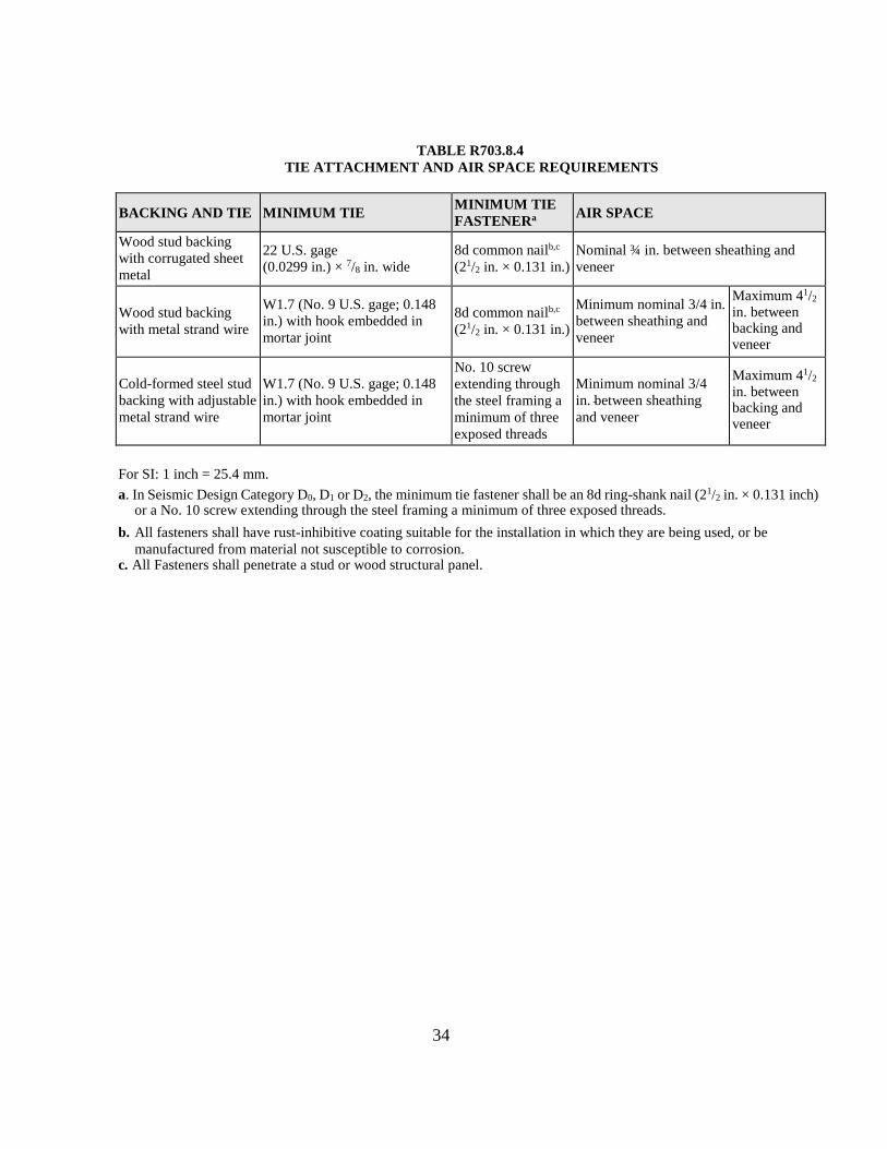
34
TABLE R703.8.4
TIE ATTACHMENT AND AIR SPACE REQUIREMENTS
BACKING AND TIE MINIMUM TIE MINIMUM TIE
FASTENERa
AIR SPACE
Wood stud backing
with corrugated sheet
metal
22 U.S. gage
(0.0299 in.) × 7/8 in. wide
8d common nailb,c
(21/2 in. × 0.131 in.)
Nominal ¾ in. between sheathing and
veneer
Wood stud backing
with metal strand wire
W1.7 (No. 9 U.S. gage; 0.148
in.) with hook embedded in
mortar joint
8d common nailb,c
(21/2 in. × 0.131 in.)
Minimum nominal 3/4 in.
between sheathing and
veneer
Maximum 41/2 in. between backing and veneer
Cold-formed steel stud
backing with adjustable
metal strand wire
W1.7 (No. 9 U.S. gage; 0.148
in.) with hook embedded in
mortar joint
No. 10 screw
extending through
the steel framing a
minimum of three
exposed threads
Minimum nominal 3/4
in. between sheathing
and veneer
Maximum 41/2 in. between backing and veneer
For SI: 1 inch = 25.4 mm.
a. In Seismic Design Category D0, D1 or D2, the minimum tie fastener shall be an 8d ring-shank nail (21/2 in. × 0.131 inch) or a No. 10 screw extending through the steel framing a minimum of three exposed threads.
b. All fasteners shall have rust-inhibitive coating suitable for the installation in which they are being used, or be
manufactured from material not susceptible to corrosion. c. All Fasteners shall penetrate a stud or wood structural panel.

35
CHAPTER 9
ROOF ASSEMBLIES
SECTION R905
REQUIREMENTS FOR ROOF COVERINGS
R905.2.8.5 Drip edge. A drip edge shall be provided at
eaves and gables of shingle roofs. Adjacent pieces of drip
edge shall be overlapped a minimum of 2 inches (51
mm). Drip edges shall extend a minimum of 0.25 inch
(6.4 mm) below the roof sheathing and extend up the roof
deck a minimum of 2 inches (51 mm). Drip edges shall
be mechanically fastened to the roof deck at a maximum
of 12 inches (305 mm) on center with fasteners as
specified in Section R905.2.5. Underlayment shall be
installed over the drip edge along eaves and under the
drip edge on gables. Alternate methods to the standard
metal drip edge may include site formed coil stock that
creates a drip line as intended by the code. Wood,
composite and manufactured trim installed on the fascia
shall create a drip line to prevent water from running back
under the shingles which will meet the requirements of
the drip edge.
36
CHAPTER 11
ENERGY EFFICIENCY
SECTION N1101
GENERAL
N1101.1 Scope. This chapter regulates the energy efficiency
for the design and construction of buildings regulated by the
2009 International Energy Conservation Code.
N1101.2 Compliance. Compliance shall be demonstrated by
meeting the requirements of the International Energy
Conservation Code and Sections N1101.2.1 and N1101.2.2 of
this code where applicable.
N1101.2.1 Basement walls. Walls associated with
basements that make up the building thermal envelope shall
be insulated from the inside or outside of the basement wall
from the top of the basement wall below grade to the design
frost depth in accordance with Section R403.1.4. Walls
associated with unconditioned basements shall meet this
requirement unless the floor overhead is insulated in
accordance with Sections 402.1.1 and 402.2.6 of the 2009
International Energy Conservation Code.
N1101.2.2 Slab on grade floors. Slab on grade floors
constructed in accordance with Figure N1101.2.2 shall be
permitted as an alternative insulation method.

37
Figure N1101.2.2
Alternative insulation method for slab on grade floors

38
CHAPTER 13
GENERAL MECHANICAL SYSTEM REQUIREMENTS
SECTION M1301
GENERAL
M1301.1. Scope. The provisions of this chapter shall govern
the installation of mechanical systems not specifically
covered in other chapters applicable to mechanical systems.
Installation of mechanical appliances, equipment and systems
not addressed by this code shall comply with the applicable
provisions of the International Mechanical Code and NFPA
54 National Fuel Gas Code.
SECTION M1305
APPLIANCE ACCESS
M1305.1 Appliance access for inspection service, repair and
replacement. Appliances shall be accessible for inspection,
service, repair and replacement without removing permanent
construction, other appliances, or any other piping or ducts
not connected to the appliance being inspected, serviced,
repaired or replaced. A level working space not less than 30
inches deep and 30 inches wide (762 mm by 762 mm) shall
be provided in front of the control side to service an
appliance.
Exception: Structural members located within the 30-inch
by 30-inch work space shall be acceptable if it does not
impede serviceability of the equipment.
M1305.1.3 Appliances in attics. Attics containing
appliances shall be provided with an opening and a clear
and unobstructed passageway large enough to allow
removal of the largest appliance, but not less than 30 inches
(762 mm) high and 22 inches (559 mm) wide and not to
exceed half the length of the structure from the opening to
the appliance. The passageway shall have continuous solid
flooring in accordance with Chapter 5 not less than 24
inches (610 mm) wide. A level service space not less than
30 inches (762 mm) deep and 30 inches (762 mm) wide
shall be present along all sides of the appliance where
access is required. The clear access opening dimensions
shall be not less than of 20 inches by 30 inches (508 mm by
762 mm), and large enough to allow removal of the largest
appliance.
Exceptions:
1. The passageway and level service space are not
required where the appliance can be serviced
and removed through the required opening.
2. Where the passageway is unobstructed and not
less than 6 feet (1829 mm) high and 22 inches
(559 mm) wide for its entire length, the
passageway shall be not more than 50 feet (15
250 mm) long.
M1305.1.4 Appliances under floors. Underfloor spaces
containing appliances shall be provided with an
unobstructed passageway large enough to remove the
largest appliance, but not less than 30 inches (762 mm) high
and 22 inches (559 mm) wide, nor more than half the length
of the structure from the opening to the appliance. A level
service space not less than 30 inches (762 mm) deep and 30
inches (762 mm) wide shall be present at the front or service
side of the appliance. If the depth of the passageway or the
service space exceeds 12 inches (305 mm) below the
adjoining grade, the walls of the passageway shall be lined
with concrete or masonry extending 4 inches (102 mm)
above the adjoining grade in accordance with Chapter 4.
The rough-framed access opening dimensions shall be not
less than 22 inches by 30 inches (559 mm by 762 mm), and
large enough to remove the largest appliance.
Exceptions:
1. The passageway is not required where the level
service space is present when the access is open,
and the appliance can be serviced and removed
through the required opening.
2. Where the passageway is unobstructed and not
less than 6 feet high (1929 mm) and 22 inches (559
mm) wide for its entire length, the passageway
shall not be limited in length.

39
CHAPTER 14
HEATING AND COOLING EQUIPMENT AND APPLIANCES
SECTION M1403
HEAT PUMP EQUIPMENT
M1403.1 Heat pumps. Electric heat pumps shall be listed
and labeled in accordance with UL 1995 or UL/CSA/ANCE
60335-2-40 and installed in accordance with the
manufacturer’s installation instructions.
SECTION M1411
HEATING AND COOLING EQUIPMENT
M1411.8 Locking access port caps. Section M1411.8 shall
be DELETED in its entirety.
SECTION M1416
MINI-SPLIT HEAT PUMPS
M1416.1 General. Mini-split heat pumps shall be installed
in accordance with Section R303.9 and the manufacturer’s
installation instructions.

40
CHAPTER 15
EXHAUST SYSTEMS
SECTION M1502
CLOTHES DRYER EXHAUST
M1502.4.1.1 Alternate Material and installation.
Clothes dryer exhaust ducts are permitted to be made of
PVC and CPVC plastic provided they shall be a nominal
4 inches in diameter. The alternate material shall only be
installed below a slab on grade floor and backfilled with
sand or gravel. Each dryer exhaust duct joint shall be
secured with PVC or CPVC solvent glue and each joint
shall provide a smooth interior finish. The maximum
installed exhaust duct length shall conform to Section
M1502.4.4.1 and labeled in accordance with Section
M1502.4.5. The dryer exhaust duct shall be installed to
provide positive drainage to the termination and shall not
permit the collection of condensate. The exhaust duct
shall only extend a maximum of 1 inch above the slab on
grade floor for connection to the appliance.
M1502.4.4.1 Accessibility and identification. Dryer
exhaust duct power ventilators shall be accessible for
inspection, service, repair and replacement without
removing permanent construction and identified on a
permanent label or tag at the appliance or access door to
the appliance. A permanent label or tag giving
notification to the occupant of the use of a dryer exhaust
duct power ventilator shall be located within 6 feet (1829
mm) of the dryer.
SECTION M1503
RANGE HOODS
M1503.2 Duct material. Ducts serving range hoods shall be
constructed of galvanized steel, stainless steel, copper, or
other manufacturer approved material.
Exception: Ducts for domestic kitchen cooking appliances
equipped with down-draft exhaust systems shall be
permitted to be constructed of schedule 40 PVC pipe and
fittings provided that the installation complies with all of
the following:
1. The duct is installed under a concrete slab poured on
grade.
2. The underfloor trench in which the duct is installed is
completely backfilled with sand or gravel.
3. The PVC duct extends not more than 1 inch (25 mm)
above the indoor concrete floor surface.
4. The PVC duct extends not more than 1 inch (25 mm)
above grade outside of the building.
5. The PVC ducts are solvent cemented.
M1503.4 Makeup air required. Exhaust hood systems
capable of exhausting in excess of 400 cubic feet per minute
(0.19 m3/s) shall be mechanically or naturally provided with
makeup air at a rate approximately equal to the exhaust air
rate. Such makeup air systems shall be equipped with not less
than one damper. Each damper shall be an electrically
operated damper that automatically opens when the exhaust
system operates. Dampers shall be accessible for inspection,
service, repair and replacement without removing permanent
construction or any other ducts not connected to the damper
being inspected, serviced, repaired or replaced.

41
CHAPTER 16
DUCT SYSTEMS
SECTION M1601
DUCT CONSTRUCTION
M1601.4.1 Joints, seams and connections. Longitudinal
and transverse joints, seams and connections in metallic and
nonmetallic ducts shall be constructed as specified in
SMACNA HVAC Duct Construction Standards—Metal
and Flexible and NAIMA Fibrous Glass Duct Construction
Standards. Joints, longitudinal and transverse seams, and
connections in ductwork shall be securely fastened and
sealed with welds, gaskets, mastics (adhesives), mastic-
plus-embedded-fabric systems, liquid sealants or tapes.
Tapes and mastics used to seal fibrous glass ductwork shall
be listed and labeled in accordance with UL 181A and shall
be marked “181A-P” for pressure-sensitive tape, “181 A-
M” for mastic or “181 A-H” for heat-sensitive tape.
Tapes and mastics used to seal flexible air ducts and
flexible air connectors shall comply with UL 181B and
shall be marked “181 B-FX” for pressure-sensitive tape or
“181 BM” for mastic. Duct connections to flanges of air
distribution system equipment shall be sealed and
mechanically fastened. Mechanical fasteners for use with
flexible nonmetallic air ducts shall comply
with UL 181B and shall be marked 181B-C. Crimp joints
for round metallic ducts shall have a contact lap of not less
than 1 inch (25 mm) and shall be mechanically fastened by
means of not less than three sheet-metal screws or rivets
equally spaced around the joint.
Closure systems used to seal all ductwork shall be
installed in accordance with the manufacturers’
instructions.
Exceptions:
1. Spray polyurethane foam shall be permitted to be
applied without additional joint seals.
2. Where a duct connection is made that is partially
inaccessible, three screws or rivets shall be equally
spaced on the exposed portion of the joint so as to
prevent a hinge effect.
3. Continuously welded and locking-type longitudinal
joints and seams in ducts operating at static pressures
less than 2 inches of water column (500 Pa) pressure
classification shall not require additional closure
systems.

42
CHAPTER 17
COMBUSTION AIR
Chapter 17 Combustion Air. Chapter 17 of the 2015 IRC shall be DELETED in their entirety.
CHAPTER 18
CHIMNEYS AND VENTS
Chapter 18 Chimneys and Vents. Chapter 18 of the 2015 IRC shall be DELETED in its entirety.
CHAPTER 19
SPECIAL APPLIANCES, EQUIPMENT AND SYSTEMS
Chapter 19 Special Appliances, Equipment and Systems. Chapter 19 of the 2015 IRC shall be DELETED in its entirety.
CHAPTER 20
BOILERS AND WATER HEATERS
Chapter 20 Boilers and Water Heaters. Chapter 20 of the 2015 IRC shall be DELETED in its entirety.
CHAPTER 24
FUEL GAS
Chapter 24 Fuel Gas. Chapter 24 of the 2015 IRC shall be DELETED in its entirety.
CHAPTER 25
PLUMBING ADMINISTRATION
Chapter 25 Plumbing Administration. Chapter 25 of the 2015 IRC shall be DELETED in its entirety.
CHAPTER 26
GENERAL PLUMBING REQUIREMENTS
Chapter 26 General Plumbing Requirements. Chapter 26 of the 2015 IRC shall be DELETED in its entirety.
CHAPTER 27
PLUMBING FIXTURES
Chapter 27 Plumbing Fixtures. Chapter 27 of the 2015 IRC shall be DELETED in its entirety.
CHAPTER 28
WATER HEATERS
Chapter 28 Water Heaters. Chapter 28 of the 2015 IRC shall be DELETED in its entirety.
CHAPTER 29
WATER SUPPLY AND DISTRIBUTION
Chapter 29 Water Supply and Distribution. Chapter 29 of the 2015 IRC shall be DELETED except for Section P2904 Dwelling
Unit Fire Sprinkler Systems.
CHAPTER 30
SANITARY DRAINAGE
Chapter 30 Sanitary Drainage. Chapter 30 of the 2015 IRC shall be DELETED in its entirety.
CHAPTER 31
VENTS
Chapter 31 Vents. Chapter 31 of the 2015 IRC shall be DELETED in its entirety.

43
CHAPTER 32
TRAPS
Chapter 32 Traps. Chapter 32 of the 2015 IRC shall be DELETED in its entirety.
CHAPTER 33
STORM DRAINS
Chapter 33 Storm Drains. Chapter 33 of the 2015 IRC shall be DELETED in its entirety.
CHAPTER 34
GENERAL REQUIREMENTS
Chapter 34 General Requirements. Chapter 34 of the 2015 IRC shall be DELETED in its entirety.
CHAPTER 35
ELECTRICAL DEFINITIONS
Chapter 35 Electrical Definitions. Chapter 35 of the 2015 IRC shall be DELETED in its entirety.
CHAPTER 36
SERVICES
Chapter 36 Services. Chapter 33 of the 2015 IRC shall be DELETED in its entirety.
CHAPTER 37
BRANCH CIRCUIT AND FEEDER REQUIREMENTS
Chapter 37 Branch Circuit and Feeder Requirements. Chapter 37 of the 2015 IRC shall be DELETED in its entirety.
CHAPTER 38
WIRING METHODS
Chapter 38 Wiring Methods. Chapter 38 of the 2015 IRC shall be DELETED in its entirety.
CHAPTER 39
POWER AND LIGHTING DISTRIBUTION
Chapter 39 Power and Lighting Distribution. Chapter 39 of the 2015 IRC shall be DELETED in its entirety.
CHAPTER 40
DEVICES AND LUMINAIRES
Chapter 40 Devices and Luminaires. Chapter 40 of the 2015 IRC shall be DELETED in its entirety.
CHAPTER 41
APPLIANCE INSTALLATION
Chapter 41 Vents. Chapter 41 of the 2015 IRC shall be DELETED in its entirety.
CHAPTER 42
SWIMMING POOLS
Chapter 42 Swimming Pools. Chapter 42 of the 2015 IRC shall be DELETED in its entirety.
CHAPTER 43
CLASS 2 REMOTE-CONTROL, SIGNALING AND POWER-LIMITED CIRCUITS
Chapter 43 Class 2 Remote-Control, Signaling and Power-Limited Circuits. Chapter 43 of the 2015 IRC shall be DELETED
in its entirety.

44
CHAPTER 44
REFERENCED STANDARDS
AWC American Wood
Council 222 Catocin
Circle, Suite 201
Leesburg, VA 20175
Standard Referenced Reference in code Number Title section number
AWC PRWDC6---2012 Prescriptive Residential Wood Deck Construction guide……………………..……………....…R301.1.1
ANSI American National Standards Institute
25 West 43rd Street 4th Floor
New York NY 10036
Standard Referenced Reference in code Number Title section number
ANSI/NSPI 3-99 Standard for Permanently Installed Residential Spas R326.4.1
ANSI/NSPI 5-03 Standard for Residential In-ground Swimming Pools………………………… ……………....R326.3.1
ANSI/APSP 7-06 Standard for Suction Entrapment Avoidance in Swimming Pools, Wadding Pools,
Spas, Hot Tubs And Catch Basins………………………………………………………………R326.6.1
ASTM ASTM International
100 Barr Harbor Drive
West Conshohocken PA 19428
Standard Referenced Reference in code Number Title section number
ASTM F 1346 – 91 Performance Specification (2003) for Safety Covers and Labeling Requirements for All
Covers for Swimming Pools Spas and Hot Tubs…………………………………….R326.6.2
KY CODES Department of Housing,
Buildings and Construction
101 Sea Hero Road, Suite 100
Frankfort, Kentucky 40601-5412
Standard Referenced Reference in code Number Title section number

45
KSPC Kentucky State Plumbing Code………………………………………….. Chapters 25 through 32
KSB & PV & PL-03 Kentucky State Boiler and Pressure Vessel and Piping Law……………….…………….M2001.1
FEMA Federal Emergency Management Agency
500C. Street SW
Washington,D.C.20472
Standard Referenced Reference in code
Number Title section number
FEMA 232 – June, 2006 Home Builders Guide to Seismic Resistant Construction………………………R301.1.1, R301.2.2
ICC International Code Council, Inc.
500 New Jersey Avenue, NW
6th Floor
Washington, DC 20001
Standard Referenced Reference in code Number Title section number
IECC—09 International Energy Conservation Code® . . . . . . . . . . .. . . . . . ... . . . … .N1101.2, N1101.5, N1101.13.1
*IFGC—15International Fuel Gas Code®, IPC—15International Plumbing Code®, IPMC—15International Property Maintenance
Code®, IPSDC—15 International Private Sewage Disposal Code®, ISPSC—15 International Swimming Pool and Spa Code TM are
deleted in the entirety and are not included as references by the Kentucky Residential Code.
NFBA National Frame Builders Association
8735 W Higgins Road suite 300
Chicago IL 60631
Standard Referenced Reference in code Number Title section number
2nd Edition Post Frame Building Design Manual……………………………………………………R301.1.1
NFPA National Fire Protection Association
1 Batterymarch Park
Quincy, MA 02269-9101
Standard Referenced Reference in code Number Title section number
54-09 National Fuel Gas Code………………….……M1301.1, M1701.1, M1801.1, M2001.1, G2401.1 70—17 National Electrical Code . . . ……………………………………………………….… .R102.9