
2018 DBSS Section 421 Structural Steelwork · Web viewHave each operator make a weld specimen not...
35
SECTION 421 STRUCTURAL STEELWORK DESCRIPTION 421.01 Scope – This Section covers the supply, fabrication, erection and quality control program of all major structural steel elements. In general, all shop connections shall be welded, and all field connections high-strength bolted. Except as otherwise specified herein, steelwork shall be fabricated and erected in accordance with the AASHTO LRFD Bridge Construction Specifications, 3 rd Edition – 2010, (including all subsequent interim revisions and updates), AASHTO LRFD Bridge Construction Specifications , Division II, Section 11. Welding and associated Work shall be in accordance with the current edition of CAN/CSA W59 – Welded Steel Construction. CSA W59 – Welded Steel Construction . Fracture control requirements, welding requirements for fracture critical members and welding requirements for primary tension members shall be in accordance with the current edition of CSA-S6 and the Ministry Supplement to CSA-S6. 421.02 Prefabrication Meeting – The Ministry will at its discretion, convene a prefabrication meeting with the Contractor to confirm the Ministry’s requirements and to review issues such as but not limited to, Schedule, lines of communication, fabricator and sub-fabricator scope of work, location of all work, procedures on quality control, welding procedures, procedures for non-destructive testing, mill certificates and heat numbers, splices, coatings, and any other specific requirements of this specification as it relates to the Work. 421.03 Alternative Details – All details shall, in general, conform to those shown on the Drawings. Any proposed variation shall be submitted in accordance with the provisions of SS 125 – Value Engineering Proposal Guidelines. The submission of drawings showing alternative details shall be prepared and sealed by a professional engineer registered with the Association of Professional Engineers and Geoscientists of the Province of British Columbia (APEGBC). ) Any consideration or implementation of a submitted VEP by the Ministry will also be in accordance with SS 125. 421.04 Working Drawings – Working drawings shall consist of the following: Shop drawings Transportation details and Erection drawings Transportation details and erection drawings shall be prepared and sealed by a professional engineer registered with the Association of Professional Engineers and Geoscientists of the Province of British Columbia (APEGBC). When the Contractor is responsible for the design of items that are detailed on the shop drawings, the shop drawings shall be prepared and sealed by a professional engineer registered with the Association of Professional Engineers and Geoscientists of British Columbia (APEGBC). APEGBC. Working drawings shall be in the same system of units as the design drawings. Lettering for notes and dimensions BC MoTI SS 2020 421 (1 of 35)
Transcript of 2018 DBSS Section 421 Structural Steelwork · Web viewHave each operator make a weld specimen not...
SECTION 421
STRUCTURAL STEELWORK
DESCRIPTION
421.01 Scope – This Section covers the supply, fabrication, erection and quality control program of all major structural steel elements.
In general, all shop connections shall be welded, and all field connections high-strength bolted.
Except as otherwise specified herein, steelwork shall be fabricated and erected in accordance with the AASHTO LRFD Bridge Construction Specifications, 3rd Edition – 2010, (including all subsequent interim revisions and updates),AASHTO LRFD Bridge Construction Specifications, Division II, Section 11. Welding and associated Work shall be in accordance with the current edition of CAN/CSA W59 – Welded Steel Construction.CSA W59 – Welded Steel Construction. Fracture control requirements, welding requirements for fracture critical members and welding requirements for primary tension members shall be in accordance with the current edition of CSA-S6 and the Ministry Supplement to CSA-S6.
421.02 Prefabrication Meeting – The Ministry will at its discretion, convene a prefabrication meeting with the Contractor to confirm the Ministry’s requirements and to review issues such as but not limited to, Schedule, lines of communication, fabricator and sub-fabricator scope of work, location of all work, procedures on quality control, welding procedures, procedures for non-destructive testing, mill certificates and heat numbers, splices, coatings, and any other specific requirements of this specification as it relates to the Work.
421.03 Alternative Details – All details shall, in general, conform to those shown on the Drawings. Any proposed variation shall be submitted in accordance with the provisions of SS 125 – Value Engineering Proposal Guidelines. The submission of drawings showing alternative details shall be prepared and sealed by a professional engineer registered with the Association of Professional Engineers and Geoscientists of the Province of British Columbia (APEGBC).)
Any consideration or implementation of a submitted VEP by the Ministry will also be in accordance with SS 125.
421.04 Working Drawings – Working drawings shall consist of the following:
Shop drawings
Transportation details and
Erection drawings
Transportation details and erection drawings shall be prepared and sealed by a professional engineer registered
with the Association of Professional Engineers and Geoscientists of the Province of British Columbia (APEGBC).
When the Contractor is responsible for the design of items that are detailed on the shop drawings, the shop drawings shall be prepared and sealed by a professional engineer registered with the Association of Professional Engineers and Geoscientists of British Columbia (APEGBC).APEGBC.
Working drawings shall be in the same system of units as the design drawings.
Lettering for notes and dimensions shall be at least 2.5 mm and 4 mm for headings. Drawings shall be legible when printed on 11” x 17” sheets.
421.04.01 Shop Drawings – Shop drawings shall show all information and details needed for the fabrication of the members including, but not limited to, such items as member shapes and dimensions, camber diagram, complete geometric information that member dimensions and shapes are based on, connection details, material and product standards, mark numbers and general arrangement of member locations, details of attachments, fastener details, weld details, mass of members, special tolerances, special handling instructions, coating details, lifting details and lifting locations.
A copy of the shop drawings shall be available at all times at the location where the components shown on the drawings are being fabricated. Changes to the steelwork from what is shown on the reviewed shop drawings, or repairs made during fabrication and/or construction, shall be indicated by the Contractor on a marked-up set of shop drawings and submitted to the Ministry Representative at the completion of the Work.
421.04.02 Transportation Details – Transportation details shall include such items as:
Description of hauling and handling equipment
Weight of members
Length and height of loads
Location and method of member support
Details for handling, storing, and loading of members.
421.04.03 Erection Drawings – Erection drawings shall show in detail the method of erection including, but not limited to, the following:
Erection procedures
Procedures for off loadingoff-loading of members upon delivery
BC MoTI SS 2020 421 (1 of 24)
STRUCTURAL STEELWORK SECTION 421
Details for temporary storage and support of members on site prior to erection
Equipment to be used
Layout or general arrangement drawing showing the layout of the members, equipment positioning, and access roads
Crane make, model, and capacity charts, boom length(s), crane placement, and access for transporting of members to crane(s)
Radii and loads for crane lifts
Rigging details
Mass of members, rigging and special installation equipment
Details for installation and removal of all falsework, temporary supports, temporary bearings, bracing, guys, dead-men, and lifting devices
Attachments to the bridge members and bridge structure for temporary support and special launching equipment
Detailed description of sequence of operations
Details for special installation equipment such as a launching truss, launching nose, head frames, spreader beams and rollers
Details for installation of members onto the permanent bearings
Traffic control plan for roadway and rail traffic
Details for protection of existing utilities affected by the erection procedures
Layout and details of fall protection and their sequence of installation.
The Contractor shall be responsible for the lateral stability of members and shall design and provide bracing as necessary until completion of the Work.
The erection drawings shall be complete in detail for all anticipated phases and conditions during erection and during the temporary support of members. The Contractor shall submit calculations, upon request, to the Ministry Representative that demonstrate that specified factored demand/capacity ratios or allowable stresses are not exceeded in members, falsework, temporary bracing and temporary supports and that member capacities and final geometry will be correct. These calculations shall be sealed by the professional engineer who sealed the erection drawings.
Falsework, temporary supports and temporary bracing shall meet the requirements of CSA Standard S269.1, “Falsework for Construction Purposesand formwork” and shall also meet all the requirements for falsework given in
Clauses 20.17 to 20.26 inclusive of the WCB Occupational Health and Safety Regulation.
A professional engineer registered with APEGBC shall be responsible for any field designs and any changes made to the erection procedures. Field designs and changes to the erection procedures must be documented and sealed by the responsible professional engineer and must be available at the Site prior to the affected erection Work being carried out.
Immediately before placement of loading on falsework, the Contractor must ensure that the falsework is inspected and a sealed engineering certificate is issued by a professional engineer registered with APEGBC which:
Indicates the specific areas inspected and
Certifies that the falsework has been erected in accordance with the latest approved erection drawings and supplementary instructions.
421.04.04 Submittals
The Contractor shall submit to the Ministry Representative one set of all working drawings in digital format. Prior to submission to the Ministry Representative, working drawings shall be reviewed and approved by the Contractor. By this review and approval, the Contractor represents that it has determined and verified all field measurements, field construction criteria, materials, and similar data, and that it has checked and coordinated each working drawing with the requirements of the work and the contract documents. The Contractor shall indicate its review and approval by including on each drawing the date and signature of a person designated by the Contractor as being responsible for the Work. Working drawings shall be submitted at least fourteen days prior to the fabrication of the Work and shall be accompanied by a transmittal listing each of the drawings submitted. At the time of submission, the Contractor must notify the Ministry Representative in writing of any deviations in the shop drawings from the requirements of the contract documents. Any Work done or materials ordered prior to the review of the working drawings shall be at the Contractor's risk. The Ministry will review the drawings for general compliance with the contract requirements.
Shop drawings will not be reviewed without the transportation details and erection drawings applicable to the members in question.
Erection will not be allowed to proceed without the Ministry Representative’s review of the method proposed.
Review of working drawings shall not relieve the Contractor of responsibility for carrying out the work in accordance with the contract documents.
If so agreed to in advance by the Ministry Representative, working drawings may be submitted in paper format. The
BC MoTI SS 2020 421 (2 of 24)
STRUCTURAL STEELWORK SECTION 421
reference to working drawing submittal copies shall be increased to four paper copies in this case. At least 14 days before fabrication is to commence and when, or as otherwise requested by the Ministry Representative, the fabricator shall submit a schedule of fabrication to the Ministry Representative in the form of a Gantt Chart. At the discretion of the Ministry, the schedule shall be updated on no less than a monthly basis. The schedule shall be made availableprovided to the Fabricator’s Quality Control and to the Ministry Representative for reference and planning of inspections and progress reporting. At the request of the Ministry Representative, the Contractor shall report any interim variations to the schedule.
421.04.05 Working Drawing Format -– The Contractor shall transmit working drawings through attachments to e-mail. Electronic attachments to an email must total no more than 7 MB and must be submitted unzipped. Drawing files shall be submitted in Portable Document Format (PDF) to print out on 11” x 17” size pages. PDF sets shall be created by “distilling” CAD sheets rather than by scanning paper plan sets. Electronic attachments greater than 7 MB in size shall be sent in two parts by separate emails, denoting “1 of 2” and “2 of 2” in the subject lines after other required subject-line information.
If agreed to by the Ministry Representative, the Contractor may employ a document and data management service such as Buzzsaw®Sharepoint to transmit working drawings. If this process is used, the limitation on drawing file size is waived. The Contractor shall be responsible for setting up the appropriate folders within the document and data management software and for providing access to these folders to the fabricator, Ministry Representative and the design engineer. The Contractor and the Ministry Representative shall send e-mail notification to each other whenever they post drawings to the document and data management folders.
The resolution of drawings shall be such that the finest detail must be legible at full scale on a 21 inch monitor without zooming in (1 -in. width on an 11” x 17” sheet is 1 in. on the monitor).
Drawings shall be black images on a white background.
All PDF sheets shall be assembled within a single file, subject to the maximum file size indicated above, ensuring that all sheets are rotated to a “ready to read” orientation within the PDF file set. Generally, 11x17 plan sheets should be in landscape and 8 1/2x11 note sheets in portrait, so that the majority of text is vertical. PDF sheets shall be ready to print out on appropriateappropriately sized paper sheets with no additional formatting required by the viewer.
Drawing sets that are not legible or that do not conform to
submission requirements will be returned to the Contractor without being reviewed and the Contractor shall submit four paper copies of the drawing set as substitutes. Drawings of large or complicated pieces, where it is not practical to show all details on an 11” x 17” sheet, may be submitted on full size paper drawings, in which case the Contractor shall submit four copies of the drawing set. When revisions to full size paper drawings are required, the Contractor shall supply four completes sets to the Ministry Representative.
421.05 Quality Control – The Contractor shall implement a quality control program to meet the Contract requirements. The quality control plan shall be made available to the Ministry Representative for review.
421.06 Quality Assurance – The Ministry will implement a quality assurance program by auditing the Contractor's quality control program and by inspection at its discretion.
The Contractor shall notify the Ministry Representative at least 14 days before fabrication has commenced. In addition, the Contractor shall provide a minimum of 48 hours notice to the Ministry Representative that a product will be available for inspection. If the schedule is subsequently changed, the Contractor shall provide the 48 hours notice from the time that the Ministry is notified of this change. If the product is not available or is not sufficiently complete for inspection as notified, at the sole discretion of the Ministry Representative, the Contractor shall be charged stand-by costs for the Ministry’s quality assurance inspector. The Contractor shall allow the Ministry Representatives representatives safe access to all parts of the Work and shall supply such information and assistance as is required. The Contractor shall provide samples of any materials requested by the Ministry. Inspection by the Ministry shall not relieve the Contractor from obligation to perform the Work in accordance with the Contract.
At its discretion and expense, the Ministry will test any weld by non-destructive testing methods, in accordance with CSA W59CSA W59. Generally, fillet welds will be tested by the dry powder magnetic particle method (MT) and butt joints by radiography (RT), or by any other method of testing the Ministry deems necessary, such as die penetrant (PT), ultrasonic (UT) and phased array ultrasonic testing methods. Selection of the appropriate testing method will be at the discretion of the Ministry.
The Ministry will attempt to schedule non-destructive testing operations so as not to interfere with the progress of the Work.
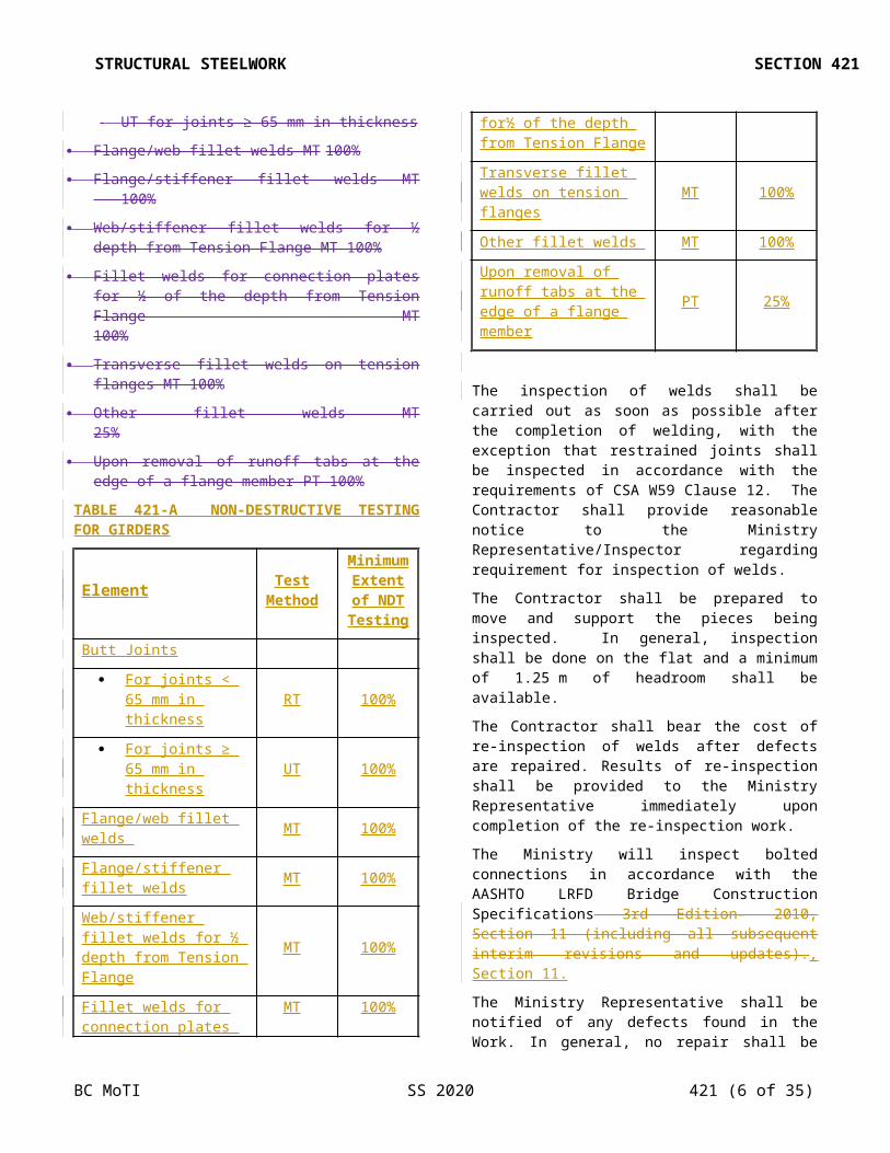
The extent of non-destructive testing will usually be as followsin accordance with Table 421-A for each girder:
Butt Joints100%
RT for joints < 65 mm in thickness
BC MoTI SS 2020 421 (3 of 24)
Woolford, David TRAN:EX, 2019-07-30,
TBD
STRUCTURAL STEELWORK SECTION 421
UT for joints ≥ 65 mm in thickness
Flange/web fillet welds MT 100%
Flange/stiffener fillet welds MT 100%
Web/stiffener fillet welds for ½ depth from Tension Flange MT 100%
Fillet welds for connection plates for ½ of the depth from Tension Flange MT 100%
Transverse fillet welds on tension flanges MT 100%
Other fillet welds MT 25%
Upon removal of runoff tabs at the edge of a flange member PT 100%
TABLE 421-A NON-DESTRUCTIVE TESTING FOR GIRDERS
Element Test Method
Minimum Extent of
NDT Testing
Butt Joints
For joints < 65 mm in thickness RT 100%
For joints ≥ 65 mm in thickness UT 100%
Flange/web fillet welds MT 100%
Flange/stiffener fillet welds MT 100%
Web/stiffener fillet welds for ½ depth from Tension Flange
MT 100%
Fillet welds for connection plates for½ of the depth from Tension Flange
MT 100%
Transverse fillet welds on tension flanges MT 100%
Other fillet welds MT 100%
Upon removal of runoff tabs at the edge of a flange member
PT 25%
The inspection of welds shall be carried out as soon as possible after the completion of welding, with the exception that restrained joints shall be inspected in accordance with the requirements of CSA W59 Clause 12. The Contractor shall provide reasonable notice to the Ministry Representative/Inspector regarding requirement for inspection of welds.
The Contractor shall be prepared to move and support the pieces being inspected. In general, inspection shall be done on the flat and a minimum of 1.25 m of headroom shall be available.
The Contractor shall bear the cost of re-inspection of welds after defects are repaired. Results of re-inspection shall be provided to the Ministry Representative immediately upon completion of the re-inspection work.
The Ministry will inspect bolted connections in accordance with the AASHTO LRFD Bridge Construction Specifications 3rd Edition– 2010, Section 11 (including all subsequent interim revisions and updates)., Section 11.
The Ministry Representative shall be notified of any defects found in the Work. In general, no repair shall be made until agreed to by the Ministry. In the case of minor corrections, as described by CSA S6-14 Section 10.23.5.4, approval to proceed may be given either verbally by the Ministry's Inspector, or in advance provided that written repair procedures are submitted for Ministry acceptance prior to the Work commencing. In such cases as repair of cracks, or repairs as described by CSA S6-14 Section 10.23.5.5, or a revised design to compensate for deficiencies, the means of correction shall be prepared and sealed by a professional engineer registered with the Association of Professional Engineers and Geoscientists of BC (APEGBC).. It shall be submitted in writing, with adequate sketches, to the Ministry for review.
The Ministry Representative may reject any items which, in itsthe Ministry Representative’s opinion, do not comply with the requirements of this specificationthe Contract. The Ministry in its sole discretion may back charge all inspection costs for the rejected material to the Contactor.
Each main member or structural component shall be audited by a Ministry quality assurance representative before it is shipped from the shop. This audit shall not relieve the Contractor of responsibility for subsequent damage or for defects which become apparent before the Work is finally accepted by the Ministry. The Contractor shall provide 5 days notice to the Ministry Representative regarding intent to ship a unit or product and the product shall be made available for inspection prior to loading and shipping.
Members shall only be allowed to be shipped out for erection after they have been approved by Quality Control and accepted by the Ministry quality assurance representative. A certificate of compliance may be issued by the Ministry quality assurance representative to acknowledge acceptance.
421.07 Quality and Details of Welds – The quality and details of welds shall be in accordance with CSA W59.
421.08 Design Specifications –The most recent edition of CSA-S6 and the Ministry Supplement to CSA-S6 shall be
BC MoTI SS 2020 421 (4 of 24)
STRUCTURAL STEELWORK SECTION 421
used in the design of alternative details and calculating the effect of stresses incurred in fabrication and erection.
No increase in allowable stresses due to vertical loads shall be used for erection conditions.
MATERIALS
421.11 Materials
421.11.01 Structural Steel – Steel shall conform to the requirements of CAN/CSA-G40.20/G40.21, and21 and shall be of the grades called for on the Drawings. Plates provided from coils shall not be used. Prior to fabrication, the Contractor shall supply to the Ministry Representative the manufacturer's mill certificates giving details of all chemical and physical properties of steel to be used in the Work. The boron content of steel shall not exceed 0.0008%.
Chemical composition of steel to be galvanized shall be in accordance with SS 421.42.
Steel shall be supplied free of surface defects and internal discontinuities, with due regard for the end use of the steel in the Work.
Edges of all plates will be subject to inspection by the Ministry. Any discontinuities will be examined and may be accepted.
The Ministry Representative shall be supplied with a record of all observed discontinuities and repair methods.
Repairs to defective plates shall not proceed until review of the proposed repair method by the Ministry Representative is completed.
421.11.02 Welding Consumables – All electrodes shall match the base metal specified in accordance with CSA W59, Table 12.1. The deposited weld metal shall provide strength, ductility, impact toughness and corrosion resistance equivalent to the base metal.
Welding consumables for all processes shall be certified by the Canadian Welding Bureau (CWB) as complying with the requirements of CSA W48.
421.11.03 High-Strength Bolts – Unless otherwise specified on the Drawings, high-strength bolts, nuts and washers shall conform to the requirements of ASTM A325F3125, grade A 325, and as follows:
a) for painted steelwork, Type 1bolts shall be provided and painted after installation in accordance with the field painting specifications.
b) for unpainted portions of weathering steel, Type 3 bolts shall be provided.
c) for painted portions of weathering steel, Type 3 bolts shall be provided and painted after installation in accordance with the field painting specifications.
d)Type 1 bolts hot-dipped galvanized to the requirements of ASTM A153/A153M shall be provided for connections of members that are galvanized.
421.11.04 Shear Connector Studs – Shear connector studs shall conform to the requirements of ASTM A108, Grades 1015, 1018 or 1020.
421.12 Material Storage and Care
421.12.01 Steel – Structural material, either plain or fabricated, shall be stored above the ground in an upright and shored position upon platforms, skids, or other supports unless otherwise permitted by the Ministry. Should permission be granted to stack the steel in a horizontal position, the Contractor shall provide sufficient support of the steel in order to prevent bending of the plate prior to incorporation into the Work. It shall be kept free from dirt and other foreign matter, and shall be protected as far as practical from corrosion. Long members shall be supported on skids placed near enough together to prevent overstress from deflection.
Prior to fabrication, all steel shall be marked for identification by heat number and specification by a marking system approved by the Ministry.
421.12.02 Welding Consumables – Electrodes and fluxes shall be stored and kept in condition as required by CSA W59, Section 5.2.
Gas for welding shall be stored in marked steel bottles and shall not be subjected to temperatures in excess of 50°C or temperatures of less than 0°C.
421.13 Fabrication – Prior to fabrication, the welders and welding operator’s qualifications, shop drawings, welding procedures, mill certificates and welding consumable certificates shall be submitted for the Ministry's review.
No fabrication, welding or coating of steelwork shall commence until permission to do so has been received from the Ministry.
421.14 Ministry’s Plant Office – The Contractor shall provide in the fabrication plant or nearby a suitable lock-up office for the sole use of the Ministry Representative throughout the period of fabrication.
The office shall be at least 2.5 m x 3 m and shall be weathertight and reasonably soundproof, provided with ample window area and ventilation, furnished with a 0.75 m x 1.2 m desk, a 1 m x 2 m drafting table, a two-drawer filing cabinet, two chairs, a drafting stool and 3 m of shelves, and equipped with a telephone, and high-speed internet access which shall be operational throughout the period of fabrication. All long-distance telephone calls will be paid for by the Ministry.
BC MoTI SS 2020 421 (5 of 24)
STRUCTURAL STEELWORK SECTION 421
The Contractor shall clean, heat and light the office throughout the period of fabrication.
EQUIPMENT
421.21 Qualifications and Equipment
421.21.01 Contractor – The Contractor shall produce evidence that the plant is currently fully approved by the CWB to the requirements of CSA W47.1, Division 1 or Division 2 prior to beginning Work.
The Fabricator shall also produce evidence of at least three years of satisfactory experience in the fabrication of bridge structural steelwork.
The Contractor shall employ or retain a registered professional engineer experienced in steel bridge fabrication, to provide guidance throughout the work.
A qualified welding supervisor shall be employed on each shift where welding is done on the work.
Prior to fabrication, the Contractor shall submit to the Ministry the names of the welding engineer, the engineer experienced in steel bridge fabrication, and the welding supervisors who are to be employed on the Work.
421.21.02 Certification – Structural steel elements shall be fabricated in plants that have third party certification under an industry recognized quality certification program specific to steel bridge fabrication.
ThirdAcceptable third party certifications acceptable include:
• the Canadian Institute of Steel Construction Steel Bridge Certification – Complex Bridges or
• the American Institute of Steel Construction Certification Program for Steel Bridge Fabricators, in either the intermediate or advanced bridge categories, as applicable to the type of Work.
Certification shall be in effect prior to the beginning of the Work, and shall be maintained throughout the period of manufacture.
421.21.03 Welders and Welding Operators – The Contractor shall produce evidence that all welders and welding operators to be employed on the Work are currently qualified by the CWB at the time of fabrication in the processes in which they are to be employed on the Work.
The Contractor shall also produce evidence relative to each welder and welding operator, that they have been executing satisfactory welding in the required processes within the six-month period previous to the award of this Contract.
421.21.04 Welding Equipment – All equipment to be
used in the Work shall be in good working order and shall be subject to the inspection of the Ministry.
For any arrangement of automatic welding, the Ministry Representative may require that a preliminary test run of the equipment be made, without welding, over the length of the joint, to prove that the disposition of the equipment and the method and accuracy of travel are satisfactory.
421.22 Welding Procedures – The Fabricator shall submit copies of the proposed welding procedures for review by the Ministry. Gas metal arc welding shall not be used. Where the submerged arc or flux cored arc process is to be used, the Ministry Representative may order that each welder and welding operator make a weld specimen not less than 1 m in length for fillet welds and 150 mm in length for butt joints. Steel of the same specifications and thickness as that to be used in the work shall be used in the specimen welds.
No welding shall be done on the Work until the welders’ and welding operators’ qualifications are established to the satisfaction of the Ministry Representative.
Welding procedures shall be accompanied by documentary proof that they have been qualified previously by the CWB at the plant where the Work is to be carried out.
The procedures shall include the following information: joint type, welding process, welding position, base metal specification, welding consumable specification and size, preheat requirements, amperage and voltage requirements, speed, polarity, and welding equipment, including a description of travel for automatic welding. Additional information, as described in CSA W47.1, Appendix C, shall also be included in the procedures.
421.23 Butt Joints – Except as called for on the Drawings, or as reviewed and approved by the Ministry’s design engineer, butt joints will not be permitted. Approval must be given prior to fabrication.
The Fabricator may submit an alternative butt joint design, to that shown on the Drawings, or propose a butt joint design if one is not shown on the Drawings, provided that all such designs have been approved by the CWB. Acceptance of alternative butt joint designs shall be subject to approval by the Ministry. Location and details of all butt joints shall be explicitly shown on the shop drawings.
421.24 Assembly and Welding Sequences – If requested by the Ministry Representative, the Contractor shall supply full details of the proposed assembly and welding sequence of any particular weldment.
CONSTRUCTION
421.31 Preparation of Material
BC MoTI SS 2020 421 (6 of 24)
STRUCTURAL STEELWORK SECTION 421
421.31.01 Straightening Material – Prior to being used in fabrication, all structural steel shall be straight and free from kinks or bends. The flatness tolerance of plate in excess of 900 mm wide shall be in accordance with the tolerances of the finished product as specified in CSA W59. If straightening is necessary, it shall be done by methods that will not injure the metal. The steel shall not be heated unless permission is given by the Ministry Representative.
In no case shall the temperature of the steel exceed 620oC. After straightening, the surfaces of the metal shall be carefully inspected for evidence of fracture and if necessary, the material shall be replaced or repaired to the satisfaction of the Ministry Representative. Sharp kinks and bends will be cause for rejection of the steel.
421.31.02 Camber – Girders shall be cambered as shown on the Drawings.
421.31.03 Edge Preparation – Steel may be cut to size by sawing, shearing, plasma cutting or flame cutting. All steel before cutting shall be marked by a method agreed to by the Quality Manager and Ministry Representative so that its specification may be immediately identified.
All cut edges shall be smooth and regular, free from fins, cracks, tears and notches. Freehand cutting shall be done only where approved by the Ministry Representative. Roughness of cut surfaces shall not exceed the American National Standards Institute ASME B46.1U. S. Standards Institute B46.1 value of 1000. Roughness exceeding this value shall be removed by machining or grinding. Occasional gouges will be tolerated only at the discretion of the Ministry Representative and shall be repaired in accordance with a procedure approved by the Ministry.
Sheared edges of plates more than 16 mm in thickness shall be planed to a depth of 6 mm.
Re-entrant flame cuts shall be cut to a radius of not less than 20 mm.
All exposed edges and corners of members, rolled or cut, which are to be coated, shall be ground to a minimum radius of 2 mm.
All corners of oxygen cut and plasma cut edges of main stress-carrying members including the outside edges of flange splice plates, except unpainted bearing stiffeners and girder webs, shall be ground to a minimum radius of 2 mm.
Special attention shall be given to the cutting of flange plates. All flange plates prepared by flame cutting shall be preheated in accordance with SS 421.34.
The Fabricator will carry out Brinell hardness testing of the edges of flange plates and flange splice plates on fracture critical members. For flanges plates, readings shall be taken near both ends and the centre on each side of the
plate for a total of 6 readings minimum per plate. For flange splice plates readings shall be taken near the centre on each side of the plates for a total of 2 readings minimum per plate. The locations and readings shall be recorded for review by the Ministry Representative. The Brinell hardness of the edges of flange plates on fracture critical members shall not exceed 220. If greater hardness is measured, the edges shall be ground by the Fabricator to remove the hard layer. The Ministry Representative may conduct Quality Assurance testing of Brinell hardness once the flanges have been prepared to meet the hardness requirements. The Contractor shall bear all costs for re-inspection and retesting.
Surfaces to be welded shall be free from loose scale, slag, rust, grease, moisture or other material that will prevent proper welding. Mill scale that withstands vigorous wire brushing, a light film of drying oil or a thin rust inhibitive coating may remain except that all mill scale shall be removed from the surfaces on which flange-to-web welds are to be made. Surfaces within 100 mm of any weld location shall be free from any paint or other material that would prevent proper welding or produce objectionable fumes while welding.
Edges of material thicker than specified in the following list shall be trimmed if and as required to produce a satisfactory welding edge wherever a weld along the edge is to carry calculated stress:
a) Sheared edges of material thicker than 12 mm;
b) Rolled edges of plates (other than Universal Mill Plates) thicker than 10 mm;
c) Toes of angles or rolled shapes (other than wide flange sections) thicker than 16 mm;
d) Universal Mill Plates or edges of flanges of wide flange section thicker than 25 mm.
421.31.04 Direction of Rolling – Steel plates for main members and splice plates for flanges and main tension members shall be cut and fabricated so that the direction of rolling is parallel to the direction of the primary stresses.
421.31.05 Bolt Holes – Standard holes for high tensile bolts shall be either punched, sub-punched and reamed, or drilled, and shall be of a nominal diameter not more than 2 mm in excess of the nominal bolt diameter, except that the following bolt/hole combinations will be permitted:
a) either 3/4 inch or M20 bolts in 22 mm holes;
b) either 7/8 inch or M22 bolts in 24 mm holes;
c) either 1 inch or M24 bolts in 27 mm holes.
Oversize or slotted bolt holes will be allowed only in special circumstances or as shown on the Drawings.
Punched holes shall be clean cut, without torn or ragged edges. The diameter of the die shall not exceed the
BC MoTI SS 2020 421 (7 of 24)
STRUCTURAL STEELWORK SECTION 421
diameter of the punch by more than 2 mm. If a punched hole must be enlarged to admit a high tensile bolt, it shall be reamed.
Reamed holes shall be cylindrical and perpendicular to the member. Where practicable, reamers shall be directed by mechanical means. Reaming shall be done with twist drills or reamers.
Drilling shall be done with twist drills or core drills. Burrs on the outside surfaces shall be removed.
Poor matching of holes will be cause for rejection.
421.31.06 Faying Surfaces – All faying surfaces of steelwork, with the exception of T section and angle section bracing on straight girder bridges, shall be cleaned by sand blasting in the shop to SSPS-SP6. Faying surfaces of steelwork to be painted shall be painted only with one coat of inorganic zinc primer. Primer coatings shall meet the Class B coating requirements as specified in CSA-S6. The class of coating shall be determined based on testing in accordance with the “Specifications for Structural Joints Using ASTM A 325 or A 490 BoltsHigh-Strength Bolts” issued by the Research Council on Structural Connections. Primers shall be supplied with a Class B certificate and be applied and cured at the conditions specified on the certificate. Over thickness will not be accepted. If over thickness occurs then the surface will be cleaned and recoated at the Contractor’s expense.
421.32 Marking – Prior to fabrication, all steel shall be marked for identification by heat number and specification by a marking system approved by the Ministry Representative. Steel which is unidentified shall not be used in the Work.
421.33 Assembly of Weldments – The shop assembly of the various components of the weldments shall be executed in accordance with CSA W59.
Tack welding shall be done by qualified welders, using the smallest size weld required to hold the components of the assembly together. Tack welds shall be incorporated into the final weld.
421.34 Preheat and Interpass Temperatures – No welding shall be done when the temperature of the base metal is lower than -18oC. At temperatures below 0oC, the steel shall be preheated to a temperature of at least 10oC in excess of that stated in CSA W59, Table 5.3.
Preheat shall be applied to all steel to be welded so that the steel within the greater of 75 mm of the weld, or the thickness of the thickest part to be welded, is heated to the temperatures shown in CSA W59, Table 5.3.
Preheat shall be applied in such a manner that moisture from the heating equipment does not penetrate the joint.
Preheat temperatures above the minimum shown in CSA W59, Table 5.3 may be required for highly restrained
joints if designated by the Ministry.
Preheat and interpass temperatures for repair of fracture critical members shall be in accordance with CSA S6-14 Table 10.14.
Preheat temperature shall in no case exceed 200oC.
Preheat requirements for tack welds shall be as in the above table except that where single pass tack welds are used and are to be incorporated and consumed in a weld made by the submerged arc process, preheat is unnecessary.
421.35 Welding – Welding shall be done by the shielded metal arc, metal-cored arc, flux-cored arc or submerged arc processes in accordance with the reviewed procedures and CSA W59, Section 5.
Any weld between the web and flange of a bending member shall be made by a mechanized submerged arc process, which provides a continuous weld throughout the length of the member.
All welding shall be done under cover and, in the case of flux-cored arc welding, shall be done in an area free from wind or draft.
Where the submerged arc process is to be used, the Contractor shall:
a) Carry out a preliminary test run of the procedure over the length of the joint to prove that the disposition of the equipment, the handling of hoses, and the method and accuracy of travel are satisfactory.
b) Have each operator make a weld specimen not less than 1200 mm in length for fillet welds and 150 mm in length for butt welds. Steel of the same specification and thickness as that to be used in the Work shall be used in the specimen welds. No welding shall be done on the Work until such a specimen is satisfactory to the Ministry Representative.
Welds in butt joints shall be extended beyond the edges of the parts to be joined by means of start and run-off tabs providing sufficient thickness to avoid the weld burning through and with a joint preparation similar to that on the main material. Welds that connect run-off tabs to the main member shall be placed inside the joint so that they are incorporated into the final weld. For manual shielded metal arc welding the width of the tabs shall be not less than the thickness of the thicker part being joined or 75 mm, whichever is greater. For submerged arc, welding the width of the tabs shall be not less than 75 mm. Each weld pass shall be carried far enough beyond the edge of the parts being joined to ensure sound welds in the joint. Tabs shall be removed upon completion by flame cutting and grinding. The weld shall be cooled without damage to the parent plate. The end of the weld shall be made smooth and flush with the edges of the abutting parts.
BC MoTI SS 2020 421 (8 of 24)
STRUCTURAL STEELWORK SECTION 421
In flux-cored arc welding the equipment shall be capable of sustaining a gas flow rate of from 0.85 to 1.25 m3/h.
Where, in the opinion of the Ministry Representative, excessive repairs are required during the fabrication of components, the fabricator shall submit a plan to the Ministry Representative for review and acceptance, which shows revisions to the fabrication process, including personnel if necessary, to reduce or eliminate future fabrication non-conformances.
421.36 Shear Connector Studs – Shear connector studs shall be welded in the locations shown on the Drawings, to the requirements of CSA W59, Section 5.5.6. Shear connectors will be inspected and shall be repaired if necessary in accordance with the same standard.
421.37 High Strength Bolts – Installation of high-strength bolts shall be in accordance with the AASHTO LRFD Bridge Construction Specifications 3rd Edition – 2010, Section 11.5.6 (including all subsequent interim revisions and updates) using the “turn of nut” method.
Galvanized bolts shall be lubricated with beeswax or other approved lubricant before installation.
Heads of bolts shall be placed on the outsides of girders and box members, and generally on the more conspicuous side, if any, of any connection.
421.38 Bent Plates – When bending plates, the plates shall be so taken from the stock plates that the bend line will be at right angles to the direction of rolling. Before bending, the corners of the plate shall be rounded to a radius of 2 mm throughout that portion of the plate at which bending is to occur. Bending shall be done by methods that will not crack, tear or otherwise injure the metal.
Cold bending and the minimum radii for cold bending shall be in accordance with CSA S6.
Hot bending of plates shall not be permitted without prior approval of the Ministry. Any proposed method for hot bending of plates shall be submitted to the Ministry for review and approval by the Ministry prior to proceeding with the work.
Bending of flange plates shall not be permitted without prior approval of the Ministry. Any proposed method for bending flange plates shall be case specific and shall be submitted to the Ministry for review and approval by the Ministry prior to proceeding with the work.
421.39 Shop Assembly of Bolted Connections – Holes in girder and truss field splices shall be drilled while assembled in the shop, or sub-punched or sub-drilled and reamed while assembled. Unless otherwise specified, the structure shall be progressively assembled in accordance with AASHTO LRFD Bridge Construction Specifications for Bridges 3rd Edition – 2010, Section 11.5.3.1 (including all subsequent interim revisions and updates)..
The Ministry shall be provided sufficient notice by the Fabricator, to allow inspection of any assembly, including camber, alignment and accuracy of holes before drilling or reaming is commenced.
Connecting parts assembled in the shop for the purpose of reaming or drilling holes shall be match-marked by a method agreed to by the Ministry to indicate the location and orientation of all pieces.
Alternatively, the Contractor may drill holes full-size using automatic drilling equipment, as described in AASHTO LRFD Bridge Construction Specifications for Bridges 3rd Edition, Section 11.4.8.3 (including all subsequent interim revisions and updates).. In this case a check assembly will be required for the first of each major structural type, as described in AASHTO LRFD Bridge Construction Specifications 3rd Edition – 2010, Section 11.5.3.3 (including all subsequent interim revisions and updates)..… Reaming of holes shall be as specified in SS 421.47, if the bolt holes do not line up during field assembly.
Progressive assembly in the yard may be allowed, subject to approval by the Ministry Representative, provided the Fabricator can demonstrate that yard assembly will provide as high a quality product as shop assembly.
421.40 Dimensional Tolerances – Except as noted herein, the dimensions of completed members shall comply with the appropriate dimensional tolerances as specified in CSA W59.
Alignment or position of secondary members shall be within ± 6 mm.
The tolerance in flange width shall be ±(b/100), where b is the flange width, but not less than 5 mm and not greater than 25 mm.
The tolerance on the width of stiffeners and plates for secondary members shall be -3 mm, +10mm.
Misalignment of stiffeners on opposite faces of a web shall be less than one third of the web thickness for bearing stiffeners and half the web thickness for intermediate stiffeners.
The maximum deviation from specified length shall be L/1000 but not over 20 mm.
Warpage of box members shall be determined by taking measurements at any two cross-sections in a member, at opposite edges of one face of the member. Warpage is defined as the distance by which any point deviates from a plane defined by the other three points. This warpage shall not exceed 1/200 of the width of the member, or 3 mm, whichever is greater.
421.41 Machined Surfaces – Machine-finished surfaces, as designated on the Drawings, shall be coated with an approved protective compound.
BC MoTI SS 2020 421 (9 of 24)
STRUCTURAL STEELWORK SECTION 421
[421.42] Galvanizing or Metallizing (if required) – All steelwork to be galvanized shall be galvanized after complete fabrication to the requirements of ASTM A123M and ASTM A385. The galvanizer shall safeguard against embrittlement as required in ASTM Practice A143. Galvanized members shall be subject, at the discretion of the Ministry Representative, to the tests for embrittlement outlined in ASTM Practice A143.
The chemical composition of steel being galvanized shall be as follows:
Carbon less than 0.25%
Phosphorus less than 0.04%
Manganese less than 1.3%
Silicon less than 0.04% or between 0.15% and 0.22%
For steel not meeting these chemical composition requirements, special galvanizing techniques shall be developed by the galvanizer to ensure that the specified coating thickness and adherence is achieved. A detailed description of the special techniques shall be submitted to the Ministry Representative for review 2 weeks prior to galvanizing.
All steelwork to be metallized shall, after complete fabrication, be treated in accordance with the current SSPC-CS23.00 / /AWS C2.23M / /NACE No. 12, Specification for the Application of Thermal Spray Coatings (Metallizing) of Aluminum, Zinc, and Their Alloys and Composites for the Corrosion Protection of Steel. The zinc coating shall not be less than 0.3 mm in thickness.
421.43 Shop Painting – The Drawings or Special Provisions shall specify whether the structure is to be painted, or what parts of a structure are to be painted. This subsection applies to those parts of the steelwork which are to be painted.
If painting is specified on the Drawings or in the Special Provisions, the structural steel of weathering steel bridges shall be painted for the larger of the following two distances from deck joint locations:
3000 mm; or
1.5 times the superstructure depth (including girder, haunch and slab thickness).
Coating work shall be in accordance with SS 216 unless noted otherwise in SS 421. For the short lengths of coating required adjacent to deck joints on weathering steel bridges, third party Quality Control inspectors shall be qualified to at least NACE CIP Level 2 NACE Level 2 or SSPC BCI Level 2 SSPC BCI Level 2.
All coatings shall be applied according to their manufacturer’s product data sheet unless specified otherwise in the Contract Special Provisions..
All steelwork which is to be painted shall be given three shop coats of paint – primer, stripe coat and midcoat. Paint shall be chosen from SS 308 System SS1. Paint shall be supplied by the Contractor.
The topcoat may be applied in the shop or in the field. The topcoat coat shall be chosen from either SS 308 System SS1 or SF2. If the topcoat is to be applied in the shop, then the Quality Control Program shall specifically address the integrity of the topcoat through to project completion.
Surfaces surrounding bolt holes at connection locations shall receive the prime coat only and shall be masked off so that no stripe coat, midcoat or topcoat paint will be under the bolt heads, washers or nuts. These masked off areas shall have the stripe coat, midcoat and topcoat paint applied in the field after installation of the bolts.
Faying surfaces shall receive the prime coat only, as per SS 421.31.06. Faying surfaces shall not be coated with the stripe coat, midcoat or topcoat paint.
Paint shall be applied in a covered area in accordance with the manufacturer's specifications and SS 216.
All edges, corners, crevices, bolts, nuts, protrusions and welds (unless ground flush) shall be stripe painted by brush for a width of 50 mm with the midcoat paint before the midcoat coat is applied. Stripe coating paint shall be applied as per SSPC-PA1 and may be applied by spray, but shall be brushed in. Stripe painting shall be allowed to cure before the midcoat coat is applied.
Unless a different coating is called for on the Drawings, the exposed steel surfaces of bearings, and bearing assemblies, shall be cleaned and painted as structural steelwork.
Surfaces shall be cleaned to "near-white" per SSPC-SP10 / NACE No. 2 and 50 µm to 75 µm (2 to 3 mils) sharp/angular profile.
The midcoat shall be applied to all surfaces including tops and sides of the top flanges, except faying surfaces and surfaces surrounding bolt holes. The midcoat shall not be applied until the primer and stripe coat are accepted by the Ministry Representative to be sufficiently cured.
Any surfaces inaccessible after erection, except faying surfaces and tops and sides of top flanges, shall be given in addition to the three shop coats, one coat of the topcoat paint appropriate for the paint system being used.
If the topcoat is to be applied in the shop, then the topcoat shall be applied after the midcoat is accepted by the Ministry Representative to be sufficiently cured.
The colour of the topcoat will be selected by the Ministry. For weathering steel, unless noted otherwise, the topcoat colour shall match the expected colour of the oxidized surfaces. The proposed colour shall be subject to the acceptance of the Ministry Representative.
BC MoTI SS 2020 421 (10 of 24)
STRUCTURAL STEELWORK SECTION 421
421.44 Marking and Shipping – Each member shall be marked by a method agreed to by the Ministry Representative with an erection mark, corresponding to the mark shown on the erection diagram.
Members shall be loaded on trucks or cars in such a manner that they can be transported to and unloaded at their destination without being damaged.
After steelwork has been delivered to Site it shall be inspected by the Contractor’s quality control inspector. The Contractor shall clean the steelwork after it has arrived at Site of any dirt, road salts, slush or other contaminants accumulated during transport and shall carry out any other surface preparation work necessary to meet the specified surface preparation requirements.
421.45 Field Assembly – The parts shall be accurately assembled as shown on the drawings and any matchmarks shall be followed. Hammering which will injure or distort the members shall not be done. Bearing surfaces and surfaces to be in permanent contact shall be cleaned before the members are assembled. Field connections shall have one half of the holes filled with bolts and cylindrical erection pins (half bolts and half pins) before final bolting. Fitting-up bolts shall be the same nominal diameter as the high tensile bolts, and cylindrical erection pins shall be 1 mm larger.
421.46 Straightening Bent Material During and after Fabrication – The straightening of plates and angles or other shapes shall be done by methods that will not produce fracture or other injury. Any proposed straightening plan, whether by heating and or mechanical straightening methods shall be case specific and shall be submitted to the Ministry Representative for review and acceptance prior to commencing with the work. Generic plans may be referred to as part of the straightening plan. The heating shall not exceed the requirements of CSA W59, Clause 5.15. After heating, the metal shall be cooled as slowly as possible, typically at ambient shop temperature.
Following the straightening of a bend or buckle, the surface of the metal shall be carefully inspected for evidence of fracture, and if necessary, replaced or repaired to the satisfaction of the Ministry. The cost of any non-visual inspection deemed necessary by the Ministry Representative as a result of the straightening process shall be borne by the Contractor.
421.47 Misfits – For all primary connections, and secondary connections having eight or more bolts, 85% of the holes shall accept bolts without reaming. The remaining 15% may be reamed to accept the designed diameter bolts. The diameter of the reamer shall be the same as the drilled hole.
Holes in plates showing more than 5 mm of offset shall be cause for rejection of that plate. New plates, if necessary,
shall be field drilled using the hole pattern in the senior member as a template.
421.48 Erection Tolerances – Unless otherwise specified, the misalignment of members after erection shall be within the dimensional tolerances specified in CSA W59, but not over 50 mm.
Misalignment shall be measured from vertical lines in the case of columns or towers, and from lines joining the ends of any test length of a member.
Joints, which are required on the drawings to be milled to bear, shall have at least 75% of the entire contact area in full bearing. The separations of any remaining portions shall not exceed 0.25 mm except locally at toes of flanges where a separation of 0.60 mm is permissible.
Where joints are not milled, the opening shall not exceed 13 mm.
421.49 Field Painting – This section applies to those parts of the steelwork which are to be painted. Coating Work shall be in accordance with SS216 unless noted otherwise in SS 421. After the completion of all deck and overhead concrete Work, steelwork shall be thoroughly cleaned of all rust, dirt, dust, oil and other foreign materials. Non-visible salts shall be removed in accordance with SSPC-SP WJ-4 to meet the NVC levels per SS216.07.02.02to meet the SSPC-SP12 / NACE No. 5 NV--2 levels. The shop coats of paint shall be touched up as necessary.
421.49.01 Field Touch-up – Bare, rusty or damaged areas shall be cleaned to SSPC-SP11, Power Tool Cleaning to Bare Metal. Feather edges into the existing coating and build the coating as per SS 216. Build the coating using coatings from the specified SS 308 System. The coating system shall be from the same manufacturer as the shop coating system on the steel.
After installation, Type 3 bolts, nuts and washers in the areas to be painted shall be cleaned to SSPC-SP11, Power Tool Cleaning to Bare Metal. These bolts, nuts and washers shall then receive the prime coat, stripe coat, midcoat and topcoat paint.
The masked off surfaces surrounding the bolt holes at connection locations shall be cleaned and shall receive the stripe coat, midcoat and topcoat paint.
421.49.02 Topcoat – The topcoat coat shall be chosen from either SS 308 System SS1 or SF2.
If the topcoat has not been applied in the shop, then the steelwork shall be given one topcoat coat of paint applied in accordance with the manufacturer's specifications and SS 216.
The colour of the finish coat will be selected by the Ministry. For weathering steel, unless noted otherwise, the topcoat colour shall match the expected colour of the oxidized surfaces. The proposed colour shall be subject to
BC MoTI SS 2020 421 (11 of 24)
STRUCTURAL STEELWORK SECTION 421
the acceptance of the Ministry Representative.
At the completion of the Contract, all steelwork, painted or unpainted, shall be cleaned of concrete spatter, mud, oil and other foreign materials.
421.50 Unpainted Weathering Steel – In the case of unpainted weathering steel, the outer faces of the girders and stringers, which includes the exposed edge of the top flange, the underside of the top flange, the girder web, and the top, bottom and outer edge of the bottom flange, and any other surfaces mentioned in the Special Provisions, shall present a uniform surface free of mill scale and shall be sandblasted to SSPC-SP6 prior to installation. Cleaning shall also include all shop marks located on the exterior faces of the girders, and in all areas of interior girders that are readily visible to the public, as determined by the Ministry Representative. Concrete splatter adhering to the steel surfaces after the construction of the deck shall be removed and the steel surfaces cleaned.
421.51 Touch-up of Galvanizing and Metallizing – All field welds and other damage in galvanized and metallized coatings shall be touched up as follows:
If the Drawings or Special Provisions call for touch-up by metallizing, the damaged areas shall be locally sandblasted to "near white" per SSPC-SP10 / NACE No. 2. All dry abrasive blast cleaned areas shall be metallized in accordance with SSPC-CS23.00/AWS C2.23M/NACE No. 12, Specification for the Application of Thermal Spray Coatings (Metallizing) of Aluminum, Zinc, and Their Alloys and Composites for the Corrosion Protection of Steel, to provide a zinc coating not less than 0.3 mm in thickness.
Cut metal edges may be harder and consequently have less profile. If that is the case, they shall be ground back to softer metal and reblasted to achieve the specified profile.
Otherwise, the damaged areas shall be thoroughly cleaned and painted with two coats of Ministry-approved organic zinc-rich paint.
QUALITY CONTROL PROGRAM
421.61 Quality Control Program – These Subsections describe the general Quality Control Program required by the Ministry for any Fabricator undertaking the fabrication of permanent steel bridges and steel bridge components. The Quality Control Program shall be part of the overall Quality Management Plan for the project.
The term "Quality Control" defines those activities that the Fabricator performs to conform to the contract.
The term "Quality Assurance" defines those activities that the Ministry performs to audit the Contractor's quality control program and to ensure conformance to the Contract.
These Subsections contain statements of the Quality Objectives and Policies that the Ministry considers essential for successful and economical quality management. They also outline the Procedures and Documentation to implement and confirm that objectives are met.
The provisions of the Quality Control Program set forth in these Subsections shall apply to all steel bridges and bridge components contracted by or for the Ministry.
These Subsections require the establishment of a Quality Organization with the responsibility for the successful and timely implementation of all necessary Quality Control activities. Some positions shown in the Suggested Organization Chart may be held by the same individual. For example, the General Manager may also be the Contract Administrative Manager and the Purchasing Manager. The Plant Superintendent may also be the Receiver and the Welding Supervisor.
421.62 Quality Objectives and Policies
421.62.01 Quality Objectives – The Quality Objectives of the Ministry cover all steel bridges and steel bridge components produced under contract to the Ministry, as follows:
a) Completed products shall conform fully to the governing Codes and Specifications stipulated in the Contract.
b) The Quality Control Program shall be fully integrated into the ongoing manufacturing activities of the Fabricator.
c) The operations of the Quality Control Program shall protect the interests of the Ministry with respect to scheduled delivery date and contracted price.
421.62.02 Quality Policy – The Quality Policy ensures that the product meets the Quality requirements of the Contract, is delivered on time, and is produced in a cost-effective manner.
The Quality Control Program applies to all stages of the design, drafting, procurement, manufacturing and testing of the product.
A Fabricator’s Quality Control Manager shall be appointed with defined responsibilities in resolving quality matters and shall report to a senior management level. At each hold point, the Fabricator’s Quality Control Manager shall:
Document the successful completion of each stage as it progresses through fabrication and erection;
Identify and report nonconforming components;
Initiate or recommend disposition of nonconforming components;
Verify corrections.
BC MoTI SS 2020 421 (12 of 24)
STRUCTURAL STEELWORK SECTION 421
Any persons assigned to perform quality control inspections shall be other than those performing or directly supervising the Work and they shall not report directly to immediate supervisors responsible for producing the Work.
The Quality Control Program is not subordinate to any design, drafting, procurement, manufacturing or testing activities.
421.63 Scope of the Quality Control Program – The Quality Control Program governs the fabrication of steel bridges and bridge components for the Ministry of Transportation and Infrastructure. The sSuggested Organization Chart is shown in Figure 1.
The Fabricator’s General Manager shall be responsible for:
adhering to the Quality Control Program in all respects.
ensuring that completed bridges or bridge components shall conform fully to the applicable design and to the fabrication and welding codes stipulated in the Contract.
ensuring that all required documentation is produced according to the Quality Control Program.
421.64 Range of Capability – The Fabricator shall provide the necessary knowledge, skill (in-house or on a contract basis) and equipment to perform the following work on steel bridges and bridge components:
Design of connections and joints not shown on Drawings (if applicable);
Preparation of shop fabrication drawings (if applicable);
Preparation of bills of material;
Preparation of material requisitions and purchase orders;
Receiving, checking and storing materials for bridges;
Layout, cutting, forming and fitting of parts;
Assembly, tacking and welding;
Dimensional checking and verification;
Resolution of non-conformances;
Documentation of all stages of work with capability of tracking all major components;
Cleaning, painting, storing and shipping;
Erection of bridges and bridge components (if applicable).
421.65 Drawings and Specifications – The Fabricator’s Chief Draftsperson shall:
obtain the latest revision of the design drawings and
Sspecifications for the Work;
submit shop drawings and erection drawings to the Ministry Representative for acceptance before commencement of the Work;
prepare material requisitions containing a full description of the material sizes, material specifications, and certifications required for conformance to the Contract;
deliver the material requisitions to the Purchasing Manager in ample time to permit ordering, delivery and documentation without delaying the Work;
issue requisitions for all sub-contracted drafting work and shall ensure that all conditions of the Contract are part of such sub-contracts.
The Fabricator’s Chief Design Engineer shall be responsible for the design of any connections or joints not shown on the design Drawings; and for the design of the erection procedures and any special erection equipment needed.
421.66 Material Control – All materials for the Work shall be ordered by the Fabricator’s Purchasing Manager in full conformance with the material requisitions provided by the Fabricator’s Chief Draftsperson.
The Purchase Orders shall contain all information necessary to ensure that materials purchased will comply fully with the terms of the Contract. Where mill certificates and test reports are required, it shall be so stated on the Purchase Order. Instructions shall state when the certificates and reports are to be delivered to the Fabricator.
If a supplier proposes a substitute for any material, the Fabricator’s Purchasing Manager shall refer the proposed substitution to the Fabricator’s Chief Design Engineer for review. If the substitute is acceptable to the Ministry Representative, the Fabricator’s Chief Draftsperson shall amend all drawings and requisitions, withdraw old issues, and issue the new versions.
The Fabricator’s Receiver shall:
inspect all materials on arrival for conformance with the Purchase Orders;
confirm that mill certificates and test reports are provided and that they correctly identify the materials delivered;
arrange with the Fabricator’s Plant Superintendent to store all materials for the Contract in segregated areas. Clear identification with the Contract shall be provided;
issue a non-conformance report covering overage, shortage or damage to the materials, and copies of the report shall be provided to the Fabricator’s Purchasing
BC MoTI SS 2020 421 (13 of 24)
STRUCTURAL STEELWORK SECTION 421
Manager and the Quality Control Manager.
The Fabricator’s Purchasing Manager shall deliver all documentation to the Fabricator’s Quality Control Manager for inclusion in the Quality Control file for the Contract.
421.67 In-Progress Inspection and Reporting – The Fabricator’s Quality Control Manager shall ensure that only documented materials are used for the Contract.
All materials intended for incorporation into the Work shall be examined after cutting to size, forming and rolling. The Fabricator’s Chief Inspector shall ensure conformance with the detailed shop drawings, shall report any non-conformance to the Fabricator’s Quality Control Manager and shall order all work affected by the non-conformance to stop, pending approval of remedial action.
Before assembling any plate girders or complex parts, the surfaces of all materials shall be examined for imperfections revealed during previous fabrication operations. The joint edge preparation for all groove welds shall be verified as conforming to the Fabricator's CWB-approved welding standards and shall be within the acceptable tolerances.
After assembly of any plate girders or complex parts, and before commencing the strength welding, the assembly shall be checked for dimensional conformance. The Fabricator’s Welding Supervisor shall ensure that the fit-up of all welded joints conforms to the approved welding standards.
The Fabricator’s Quality Control Manager shall file a written report of verification with the Fabricator’s General Manager and report any non-conformance.
421.68 Correction of Non-conformance – When a non-conformance is encountered, the Fabricator’s Quality Control Manager shall determine a recommended disposition and obtain the Ministry's approval as quickly as possible.
If there is non-conformance to the material specification stipulated in the Purchase Order, the Fabricator’s Purchasing Manager shall immediately find out the reasons for the delivery of non-conforming material. If the material is of a grade superior to that ordered, the Fabricator’s Quality Control Manager and the Chief Engineer shall be notified. They shall verify that the material is an acceptable alternative in all respects, and this verification shall include consultation with the Ministry Representative. If the material is of a grade inferior to that ordered, it shall be rejected and the correct material or a superior material shall be obtained.
If there is non-conformance of material delivery that will delay production, the Contract Administration Manager and Fabricator’s Plant Superintendent shall be notified immediately. They shall be given revised delivery dates
for the adjustment of production scheduling. The Fabricator’s General Manager shall determine the alternatives available and shall notify the Ministry Representative.
If there are non-conformities in material preparation, assembly, joint edge preparation and fit-up before strength welding, the Fabricator’s Quality Control Manager and Welding Supervisor shall immediately review the non-conformance and notify the Fabricator’s Chief Design Engineer who may require further investigation prior to submitting corrective action to the Ministry Representative for approval. If the necessary corrective action will result in delay to production, the Fabricator’s General Manager shall be notified for adjustment to the production schedule. The Fabricator’s Plant Superintendent shall inform the Fabricator’s Quality Control Manager when the corrective actions are being done so that conformance can be verified and the non-conformance report cancelled.
421.69 Welding – All welding on structural and mechanical components shall be done by the company certified to CSA W47.1 (Division 1 or 2), W47.2-M (Division 2.1 or better) and W186-M as applicable, and shall be done in accordance with the Fabricator's CWB-approved welding standards.
The edge preparations for all groove welds shall conform to the dimensions established in the approved welding standards.
If the joint is to be welded from one side only without back-gouging, the root gap and root face shall be checked to ensure conformance with the required geometry so that the root pass can be successfully completed.
The strength level and chemical composition of all filler materials used in structural and mechanical assemblies shall conform to the approved shop drawings.
All welding consumables shall conform to the approved welding standards and shall be received, stored and conditioned according to the applicable welding standards.
Any preheat required before welding shall be according to the approved welding standards.
The welding procedure followed in welding any joint in a structural or mechanical component shall conform to the applicable Data Sheet in the approved welding standards.
All welders and welding operators welding on structural or mechanical contracts shall be qualified under the requirements of the CSA Standard governing certification.
421.70 Heat Treatment – This covers any post-weld heat treatment necessary to conform to the approved welding standards.
The Fabricator’s Chief Design Engineer shall:
decide whether any structural or mechanical
BC MoTI SS 2020 421 (14 of 24)
STRUCTURAL STEELWORK SECTION 421
components shall receive post-weld heat treatment to conform to the contract conditions or to the applicable Codes and Standards.
inform the Fabricator’s Chief Draftsperson of any such requirements so that they may be incorporated on to the approved shop drawings.
Any heat treatment stipulated on the approved shop drawings or contained in the approved welding standards shall be carried out at the appropriate time and according to the approved documents.
The Fabricator’s Plant Superintendent shall ensure that any heat treatment stipulated is done according to the established procedures, shall obtain all documentation and reports, and shall deliver them to the Fabricator’s Quality Control Manager.
421.71 Non-destructive Testing – The Ministry will test any weld by non-destructive testing methods, as described in SS 421.06.
The Fabricator’s Plant Superintendent shall schedule the manufacturing operation to facilitate non-destructive testing.
If non-destructive testing of any welded joint reveals imperfections that are marginally more than the acceptance standards, the Fabricator’s Quality Control Manager shall consult with the Ministry Representative regarding the location and nature of the imperfections. The effects of leaving minor defects in place shall be assessed in relationship to the loads carried by the joint and the possible adverse effects of making an unnecessary repair.
Weld repairs shall conform to the approved welding standards.
421.72 Calibration of Measurement and Test Equipment – All measurement and testing equipment owned by the Fabricator and used in the Quality Control Program shall be calibrated and re-calibrated at the intervals and in the manner stipulated in the Manufacturer's Instruction Manuals. Any adjusting devices shall be sealed or otherwise protected from unauthorized adjustment or tampering.
421.73 Records Retention – The Fabricator's record file for each Contract shall contain the pertinent drawings, purchase orders, bills of material, material mill certificates, test reports, Quality Control documents, NDT reports and certificates of compliance.
The Fabricator's record file shall be made available to the Ministry's Inspectors upon request.
Items in the Fabricator's record file shall be retained as per company policy.
The Fabricator’s Quality Control Manager shall ensure that each file is complete in all respects before it is placed in
the Company archives.
421.74 Hold Points – In planning the work flow, the Fabricator shall coordinate with the Ministry Inspector to decide "hold" points for inspection or non-destructive testing. A list of hold points shall be drawn up by the Fabricator and the Ministry Representative at a prefabrication meeting. The Ministry Representative shall be informed of progress so that delays are minimized.
The "hold" points will typically include some of, but not be limited to, the following:
verification of materials
after plate is prepared for splicing
after splicing of plates
after web to flange weld
after stiffeners are applied
camber of girders
shop assembly
cleaning and coating
bearing plate attachment
shipping arrangements
subassemblies.
Work shall not proceed past a "hold" point until it has been signed off by Quality Control and Quality Assurance. Reports shall be completed promptly.
421.75 Transportation and Installation Procedures – Transportation and installation procedures shall be prepared and submitted for review before any installation takes place on Site. The procedures shall be sealed by a professional engineer experienced in bridge erection and registered with the APEGBC. Consideration shall be given to the following items during the preparation of the procedures:
a) Girder Transportation
i) Brief description of hauling equipment;
ii) Location of girder support points;
iii) Engineering backup if supports vary from specifications.
iv) Details of coating protection during loading transporting and erection.
b) Installation Drawings
i) Bridge site plan showing piers, abutments and access roads;
ii) Crane make, crane chart, boom length(s) and
BC MoTI SS 2020 421 (15 of 24)
STRUCTURAL STEELWORK SECTION 421
crane locations;
iii) Mass of girder and access to crane(s);
iv) Special installation equipment such as a launching truss, head frames and falsework.
c) Commentary
i) Brief point form description of installation sequence.
d) Bearings
i) Placement procedure for bearings to be included for multiple span continuous girders.
e) Traffic Control
i) Any arrangements that will be made for road and/or rail traffic.
f) Utilities
i) Safety and protection.
g) Fall Protection
(i) i)Method and date of installation as required in specifications.
PAYMENT
421.91Supply and Fabrication – Payment for supply and fabrication of structural steelwork will be made at the lump sum price bid. Payment shall be for quality control, working drawings, the supply, bending, cutting, assembly and welding of steelwork, including any galvanizing or metalizing required. Payment shall also cover trial assembly and storage as necessary.
421.92 Shipping and Erection – Payment for shipping and erection of structural steelwork will be made at the lump sum price bid. Payment shall be for quality control and the loading, shipping and unloading of steelwork. Payment shall also cover falsework if necessary and the erection of steelwork.
421.93 Painting – Payment for painting of structural steelwork will be made at the lump sum price bid. Payment shall be for the surface preparation and the supply, application and touch-up of paint as required.
BC MoTI SS 2020 421 (16 of 24)
STRUCTURAL STEELWORK SECTION 421
BC MoTI SS 2020 421 (17 of 24)
STRUCTURAL STEELWORK SECTION 421
SAMPLE FORM #1 – RECEIVING REPORT
BC MoTI SS 2020 421 (18 of 24)
SECTION 421 STRUCTURAL STEELWORK
SAMPLE FORM #2
NON-CONFORMANCE REPORT
BRIDGE NAME:
BRIDGE NUMBER: ________________________________
JOB NUMBERS: ___________________________________
IDENTIFICATION DETAILS: __________________________________________________________
__________________________________________________________________________________
__________________________________________________________________________________
DESCRIPTION OF NON-CONFORMITY:__________________________________________________________________________________
__________________________________________________________________________________
__________________________________________________________________________________
__________________________________________________________________________________
________________________ 20____ ________________________________________Date Signature
CORRECTIVE ACTION:__________________________________________________________________________________
__________________________________________________________________________________
__________________________________________________________________________________
__________________________________________________________________________________
__________________________________________________________________________________
ACTION AGREED UPON: _____________________________ ____________________________Quality Control Supervisor Quality Assurance Inspector
DATE COMPLETED: _______________ 20 ___ ________________________________________Signature
BC MoTI SS 2020 421 (19 of 24)
SECTION 421 STRUCTURAL STEELWORK
HOLD REMOVED BY: ______________________________________ __________________ 20___Date
QUALITY CONTROL SUPERVISOR: __________________________ __________________ 20___Date
QUALITY ASSURANCE INSPECTOR: _________________________ __________________ 20___Date
BC MoTI SS 2020 421 (20 of 24)
SECTION 421 STRUCTURAL STEELWORK
SAMPLE FORM #3
MoTI
Steel Fabrication Compliance Check List
BRIDGE NAME:
BRIDGE NO. _________________________________________
MARK NUMBER/S: _________________________________________________________________
Q.C. Q.A.
Material: Mill Certificates ______ ______
(Physicals, Chemicals, Impact Category) ______ ______
Identification on materials check ______ ______
Heat number transferred and recorded ______ ______
Welding: Procedures approved for each process ______ ______
Consumables checked ______ ______
Date Completed ______ ______
BC MoTI SS 2020 421 (21 of 24)
SECTION 421 STRUCTURAL STEELWORK
SAMPLE FORM #4
MoTI
Steel Fabrication Compliance Check List
BRIDGE NAME: ______________________________________ BRIDGE NO. ________________
MARK NUMBER/S: ________________________________________________________________
Q.C. Q.A.
Welding: Weld preparation and fit up ________ ________Welding within parameters ________ ________Identification on materials check ________ ________Shear studs ________ ________Visual Inspection ________ ________NDT outside agency results ________ ________
Q.C. Q.A.
___________________________ _______________________
Req'd Actual Verified
Dimensions: Flanges Top Width 1 ____________ ____________ _______________Width 2 ____________ ____________ _______________Flatness ____________ ____________ _______________Tilt ____________ ____________ _______________
Bottom Width 1 ____________ ____________ _______________Width 2 ____________ ____________ _______________Flatness ____________ ____________ _______________Tilt ____________ ____________ _______________
Web Depth ____________ ____________ _______________
Section Length ____________ ____________ _______________Bearing Ctr. Length ____________ ____________ _______________Sole Plate Contract ____________ ____________ _______________
Camber ____________ ____________ _______________Sweep Tolerance ____________ ____________ _______________(1/1000)
Splicing Camber ____________ ____________ _______________Alignment ____________ ____________ _______________Holes ____________ ____________ _______________
Date Completed ____________ ____________ _______________
BC MoTI SS 2020 421 (22 of 24)
SECTION 421 STRUCTURAL STEELWORK
SAMPLE FORM #5
MoTI
Coating Compliance Check List
BRIDGE NAME: ______________________________________ BRIDGE NO. ________________
MARK NUMBER/S: _______________________________________________________________
Q.C. Q.A.
Coating: WHMIS Safety Data Sheets ______ _____
Technical Spec. Sheets ______ _____
Surface Preparation ______ _____
Ambient Conditions – Req'd ______ _____
- Actual ______ _____
Application ______ _____
Test Results ______ _____
Date Completed ______ _____
BC MoTI SS 2020 421 (23 of 24)
SECTION 421 STRUCTURAL STEELWORK
SAMPLE TAG #6
BC MoTI SS 2020 421 (24 of 24)