2016 University of Cincinnati baja SAE drivetrain
37
2016 University of Cincinnati Baja SAE Drivetrain A Baccalaureate thesis submitted to the Department of Mechanical and Materials Engineering College of Engineering and Applied Science University of Cincinnati In partial fulfillment of the Requirements for the degree of Bachelor of Science In Mechanical Engineering Technology By Kyle Piepmeyer April 2016 Thesis Advisor: Professor Allen Arthur i
Transcript of 2016 University of Cincinnati baja SAE drivetrain
2016 University of Cincinnati Baja SAE Drivetrain
A Baccalaureate thesis submitted to the
Department of Mechanical and Materials Engineering
College of Engineering and Applied Science
University of Cincinnati
In partial fulfillment of the
Requirements for the degree of
Bachelor of Science
In Mechanical Engineering Technology
By
Kyle Piepmeyer
April 2016
Thesis Advisor:
Professor Allen Arthur
i
2016 Bearcats Baja Drivetrain Kyle Piepmeyer
TABLE OF CONTENTS
TABLE OF CONTENTS .......................................................................................................... 2
LIST OF FIGURES .................................................................................................................. 3
LIST OF TABLES .................................................................................................................... 3
ABSTRACT .............................................................................................................................. 4
PROBLEMSTATMENT & BACKGROUND ......................................................................... 4 BACKGROUND........................................................................................................................................................................................ 4
RESEARCH .............................................................................................................................. 5 PREVIOUS YEARS ................................................................................................................................................................................... 5 SEQUENTIAL GEARBOX .......................................................................................................................................................................... 5 DUAL CLUTCH DESIGN ........................................................................................................................................................................... 6 SINGLE/ DOUBLE REDUCTION ................................................................................................................................................................ 8
DESIGN .................................................................................................................................... 9 CVT DESIGN.......................................................................................................................................................................................... 9 GEAR DESIGN ....................................................................................................................................................................................... 10 SHAFT DESIGN ...................................................................................................................................................................................... 13 CASE DESIGN ....................................................................................................................................................................................... 13 INTEGRATED REAR BRAKE ................................................................................................................................................................... 13
OPTIMIZATION .................................................................................................................... 14
MANUFACTURING ............................................................................................................. 16
RESULTS ............................................................................................................................... 18 WEIGHT GOALS .................................................................................................................................................................................... 18 BUDGET ............................................................................................................................................................................................... 19
CONCLUSIONS..................................................................................................................... 19
ACKNOWLEDGEMENTS .................................................................................................... 19
WORKS CITED ..................................................................................................................... 20
APPENDIX A ......................................................................................................................... 20
APPENDIX B ......................................................................................................................... 23
APPENDIX C ......................................................................................................................... 26
2
2016 Bearcats Baja Drivetrain Kyle Piepmeyer
LIST OF FIGURES Figure 1- Briggs and Stratton Intek 305 Engine Output Curve 5 Figure 2- ATV Gears from 1994 Kawasaki Bayou 6 Figure 3- Dual Clutch Transmission Concept Sketch 7 Figure 4- Push Slave Cylinder Concept Sketches 7 Figure 5- Shifter Positioning Concept Sketches 7 Figure 6- Single Reduction Gear Train vs. Double Reduction Gear Train 8 Figure 7- Engine, CVT, and Gearbox 9 Figure 8- Gaged Engineering GX9 CVT 10 Figure 9- 3D Model of Gearbox Internals 12 Figure 10- Rear Brake Assembly 14 Figure 11- Case FEA 15 Figure 12- Case Mount Worst Case FEA 15 Figure 13- 18”X10”X4” Billet Figure 14- Billet in Proto-Trax Machine 16 Figure 15- Finished Case Figure 16- Internals in Case 17 Figure 17- Rotor Coupler 17 Figure 18- Caliper Mount 18 Figure 19- Overall Team Budget 20 Figure 20- Assembled Gearbox 21 Figure 21- Schedule 21 Figure 22- Modified Schedule 22 Figure 23- Input Shaft FEA 23 Figure 24- Intermediate Shaft FEA 24 Figure 25- Output Shaft FEA. 25 Figure 26- Intermediate Pinion Gear 26 Figure 27- Intermediate Driven Gear 27 Figure 28- Input Shaft 28 Figure 29- Intermediate Shaft 29 Figure 30- Output Gear 30 Figure 31- Output Shaft 31 Figure 32- Brake Side Hole Table 32 Figure 33- Brake Side Depths 33 Figure 34- Brake Side Critical Dimensions 34 Figure 35- CVT Side Critical Dimensions 35 Figure 36- CVT Side Depths 36 Figure 37- CVT Side Hole Table 37
LIST OF TABLES Table 1- Input Gear Parameters 12
Table 2- Intermediate Driven Gear Parameters 12
Table 3- Intermediate Pinion Gear Parameters 12
Table 4- Output Gear Parameters 13
3
2016 Bearcats Baja Drivetrain Kyle Piepmeyer
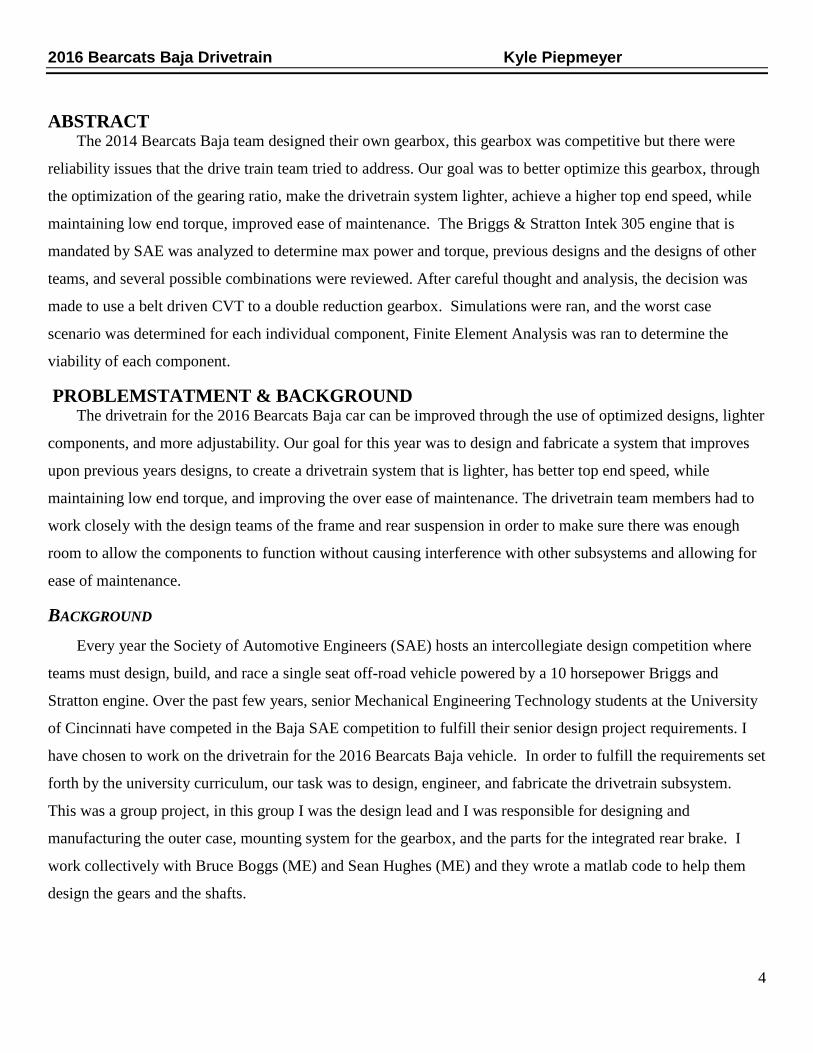
ABSTRACT The 2014 Bearcats Baja team designed their own gearbox, this gearbox was competitive but there were
reliability issues that the drive train team tried to address. Our goal was to better optimize this gearbox, through
the optimization of the gearing ratio, make the drivetrain system lighter, achieve a higher top end speed, while
maintaining low end torque, improved ease of maintenance. The Briggs & Stratton Intek 305 engine that is
mandated by SAE was analyzed to determine max power and torque, previous designs and the designs of other
teams, and several possible combinations were reviewed. After careful thought and analysis, the decision was
made to use a belt driven CVT to a double reduction gearbox. Simulations were ran, and the worst case
scenario was determined for each individual component, Finite Element Analysis was ran to determine the
viability of each component.
PROBLEMSTATMENT & BACKGROUND The drivetrain for the 2016 Bearcats Baja car can be improved through the use of optimized designs, lighter
components, and more adjustability. Our goal for this year was to design and fabricate a system that improves
upon previous years designs, to create a drivetrain system that is lighter, has better top end speed, while
maintaining low end torque, and improving the over ease of maintenance. The drivetrain team members had to
work closely with the design teams of the frame and rear suspension in order to make sure there was enough
room to allow the components to function without causing interference with other subsystems and allowing for
ease of maintenance.
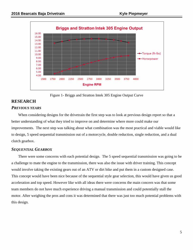
BACKGROUND Every year the Society of Automotive Engineers (SAE) hosts an intercollegiate design competition where
teams must design, build, and race a single seat off-road vehicle powered by a 10 horsepower Briggs and
Stratton engine. Over the past few years, senior Mechanical Engineering Technology students at the University
of Cincinnati have competed in the Baja SAE competition to fulfill their senior design project requirements. I
have chosen to work on the drivetrain for the 2016 Bearcats Baja vehicle. In order to fulfill the requirements set
forth by the university curriculum, our task was to design, engineer, and fabricate the drivetrain subsystem.
This was a group project, in this group I was the design lead and I was responsible for designing and
manufacturing the outer case, mounting system for the gearbox, and the parts for the integrated rear brake. I
work collectively with Bruce Boggs (ME) and Sean Hughes (ME) and they wrote a matlab code to help them
design the gears and the shafts.
4
2016 Bearcats Baja Drivetrain Kyle Piepmeyer
Figure 1- Briggs and Stratton Intek 305 Engine Output Curve
RESEARCH PREVIOUS YEARS When considering designs for the drivetrain the first step was to look at previous design report so that a
better understanding of what they tried to improve on and determine where more could make our
improvements. The next step was talking about what combination was the most practical and viable would like
to design, 5 speed sequential transmission out of a motorcycle, double reduction, single reduction, and a dual
clutch gearbox.
SEQUENTIAL GEARBOX There were some concerns with each potential design. The 5 speed sequential transmission was going to be
a challenge to mate the engine to the transmission, there was also the issue with driver training. This concept
would involve taking the existing gears out of an ATV or dirt bike and put them in a custom designed case.
This concept would have been nice because of the sequential style gear selection, this would have given us good
acceleration and top speed. However like with all ideas there were concerns the main concern was that some
team members do not have much experience driving a manual transmission and could potentially stall the
motor. After weighing the pros and cons it was determined that there was just too much potential problems with
this design.
5

2016 Bearcats Baja Drivetrain Kyle Piepmeyer
Figure 2- ATV Gears from 1994 Kawasaki Bayou
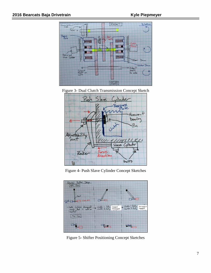
DUAL CLUTCH DESIGN Then next concept that was a potential combination was a hydraulic dual clutch transmission, which
Jonathon Forrest thought of and drew the sketches, of this concept would utilize 2 small dirt bike clutches and a
custom set of gears. These gears would be sized in order to give use the proper speed that was desired for the
car, this transmission would act as a 2 speed transmission and in which the driver would select a gear by
pushing the lever forward first and pulling it backwards for second. By moving the lever you would actuate one
of two hydraulic master cylinders depending on what gear was to be selected. The resulting pressure in the
master cylinder would actuate a push slave cylinder which through the use of a rocker arm would pull the
pressure plates together and engage the selected gear. Eventually after careful consideration and thought this
concept was ruled out because of the complexity of the design and the fact that this has never been tried before
and a reliable car was a main design focus.
6
2016 Bearcats Baja Drivetrain Kyle Piepmeyer
Figure 3- Dual Clutch Transmission Concept Sketch
Figure 4- Push Slave Cylinder Concept Sketches
Figure 5- Shifter Positioning Concept Sketches
7

2016 Bearcats Baja Drivetrain Kyle Piepmeyer
SINGLE/ DOUBLE REDUCTION There was a possibility of using a single reduction gearbox, to eliminate even more weight. However after
initial calculations it was determined that the design was not feasible because it would result in the output gear
having a 13” pitch diameter, which would be result in extremely heavy gear. There were other complications
with this design for instance the engine to be rotated 180° in order to have the wheels rotating in the correct
direction. In order to turn the engine around the gas tank would need to be relocated, re-orientate the exhaust so
that it was facing backward, change the pull start position so it could be easily started. It would have taken a lot
of work just to get the engine in the correct orientation and it would have produced much larger gears.
Ultimately decision was made to design a double reduction gearbox because it would give us a more compact
design and it would make the mounting of the gearbox and engine easier and it would be a more reliable and
robust design.
Figure 6- Single Reduction Gear Train vs. Double Reduction Gear Train
8

2016 Bearcats Baja Drivetrain Kyle Piepmeyer
DESIGN
Figure 7- Engine, CVT, and Gearbox
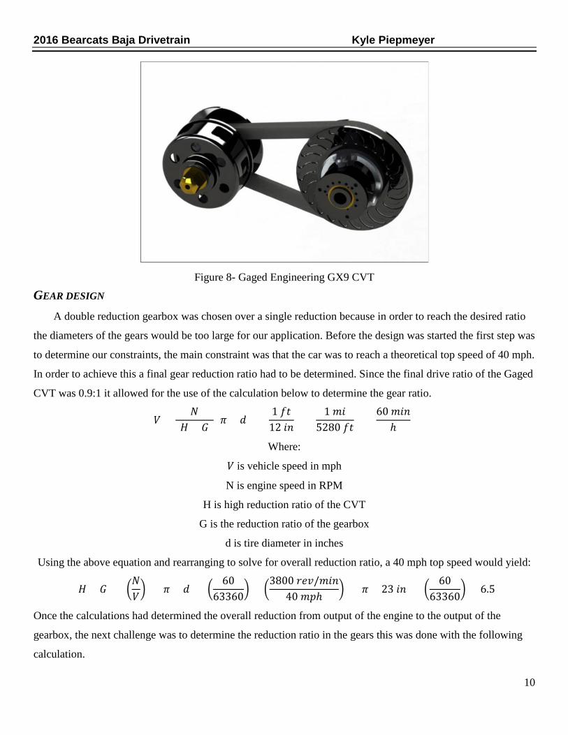
CVT DESIGN The final was narrowed down to a CVT (Continuously Variable Transmission) to an either single or double
reduction gearbox. Next research was conducted to determine which CVT was to be selected, this was based on
the previous designs and determined why they chose the CVT they did. For the 2013 team they considered two
options, a CVT from CVTech and a CVT from Gaged Engineering. The CVTech had a final drive ratio of 0.5:1,
while the Gaged had a final drive ratio of 0.9:1. The 2013 team chose to use the CVTech CVT because the
Gaged to a large amount of time in order to properly tune the CVT. They like the way the CVTech was simpler
and ready to use straight out of the box. In contrast the 2014 Baja team used the Gaged CVT because it was
lightweight and tunable. The decision to use the Gaged CVT over The CVTech Brand CVT was based on the
fact that it was lighter, tunable, and had a better final drive ratio than the CVTech. There were plans to design a
system that would allow us to easily and accurately change the center to center distance between the engine
output shaft and the input shaft for the gearbox. This idea was a direct result of working with the 2014 car, as
the car was driven the engine would vibrate and move in the mounting slots, this caused a problem when it
came to shifting gears because there was always tension on the belt which was causing the gears to rotate.
Having an adjustable center to center distance would allow us to accommodate for the stretching of the belt as
the belt was broken in. However it was decided not to procced with this concept because there was no need for
adjustment because there is no shifting of gears in this design.
9
2016 Bearcats Baja Drivetrain Kyle Piepmeyer
Figure 8- Gaged Engineering GX9 CVT
GEAR DESIGN A double reduction gearbox was chosen over a single reduction because in order to reach the desired ratio
the diameters of the gears would be too large for our application. Before the design was started the first step was
to determine our constraints, the main constraint was that the car was to reach a theoretical top speed of 40 mph.
In order to achieve this a final gear reduction ratio had to be determined. Since the final drive ratio of the Gaged
CVT was 0.9:1 it allowed for the use of the calculation below to determine the gear ratio.
𝑉𝑉 =𝑁𝑁
(𝐻𝐻 × 𝐺𝐺) (𝜋𝜋 × 𝑑𝑑) × (1 𝑓𝑓𝑓𝑓
12 𝑖𝑖𝑖𝑖) × (
1 𝑚𝑚𝑖𝑖5280 𝑓𝑓𝑓𝑓
) × (60 𝑚𝑚𝑖𝑖𝑖𝑖
ℎ)
Where:
𝑉𝑉 is vehicle speed in mph
N is engine speed in RPM
H is high reduction ratio of the CVT
G is the reduction ratio of the gearbox
d is tire diameter in inches
Using the above equation and rearranging to solve for overall reduction ratio, a 40 mph top speed would yield:
(𝐻𝐻 × 𝐺𝐺) = �𝑁𝑁𝑉𝑉� × (𝜋𝜋 × 𝑑𝑑) × �
6063360
� = �3800 𝑟𝑟𝑟𝑟𝑟𝑟/𝑚𝑚𝑖𝑖𝑖𝑖
40 𝑚𝑚𝑚𝑚ℎ� × (𝜋𝜋 × 23 𝑖𝑖𝑖𝑖) × �
6063360
� = 6.5
Once the calculations had determined the overall reduction from output of the engine to the output of the
gearbox, the next challenge was to determine the reduction ratio in the gears this was done with the following
calculation.
10

2016 Bearcats Baja Drivetrain Kyle Piepmeyer
(𝐻𝐻 × 𝐺𝐺) = 6.5
Since the high reduction of the CVT was 0.9:1 the calculation then became
(𝐻𝐻 × 0.9) = 6.5
𝐻𝐻 = 7.22
After this was calculated Bruce and Sean began using their matlab code to design the gears, their matlab code
returned the following information for the gears. The gears and shafts are all made from the following material
carburized AISI 8620 (ANSI/AGMA 2001--D04), they have a surface hardness of 64 HRC, a case hardness of
64 HRC, and a minimum core hardness of 21 HRC. All these materials were derived from the matlab code,
they found the forces on the gear teeth of all the gears, the torques on each gear by using the torque curve from
the engine on the 2014 vehicle and simple gear train calculations again. Once the tangential and radial forces on
the teeth of each gear were found, the gears were designed for stress using equations from AGMA and
assuming an initial factor of safety of 1.5. Once all the initial parameters set up in the code other parameters
were then changed to optimize our design. Changes were made to parameters such as diametral pitch, face
width, material, and useful life were then varied to come up with a configuration that would be as compact as
possible and distribute the stress on each of the gears as evenly as possible. By assuming a factor of safety of
1.5 this added to the already conservative assumptions and equations that were used. The results of all these
compounding assumptions were over designed and heavy gears. If a smaller factor of safety was chosen then
the internals could have been smaller and lighter, but these gears would not have been as strong and reliable as
the ones that were designed. There was a lot of concern with the possibility of having situation where there
would be abnormally high forces on the gears and shafts, such as being involved in a rear end or side impact, a
rollover, or the large impact stress of locking up the brakes. These situations would put massive amounts of
force on the gears and there is no way to quantify how much force would be applied in the above mentioned
situations. With all of these considerations it was determined that designing slightly heavier gears but stronger
gears would yield the most reliable and safe drivetrain.
11

2016 Bearcats Baja Drivetrain Kyle Piepmeyer
Figure 9- 3D Model of Gearbox Internals
• Input Shaft
o Pinion that is part of input shaft
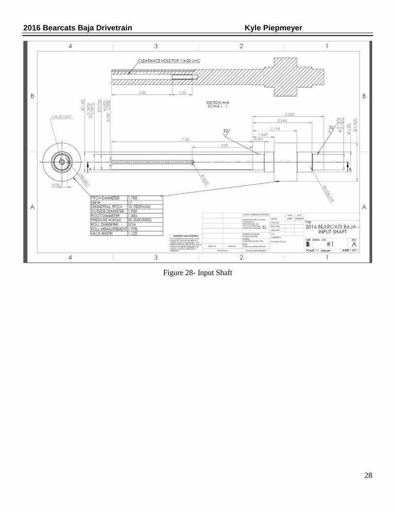
Pitch Diameter 1.700 Teeth 17 Diametral Pitch 10 (teeth/in) Face Width 1.125
Table 1- Input Gear Parameters
• Intermediate Shaft
o Gear that mates with pinion on input shaft
Pitch Diameter 5.400 Teeth 54 Diametral Pitch 10 (teeth/in) Face Width 1.125
Table 2- Intermediate Driven Gear Parameters
o Pinion that mates with gear on output shaft
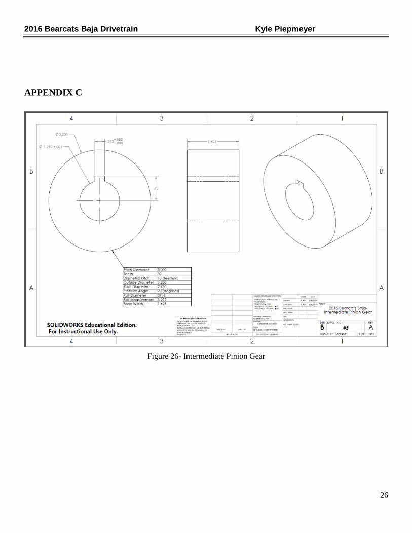
Pitch Diameter 3.000 Teeth 30 Diametral Pitch 10 (teeth/in) Face Width 1.625
Table 3- Intermediate Pinion Gear Parameters
• Output Shaft
o Gear that mates with pinion on intermediate shaft
Pitch Diameter 6.700 Teeth 67
12
2016 Bearcats Baja Drivetrain Kyle Piepmeyer
Diametral Pitch 10 (teeth/in) Face Width 1.625
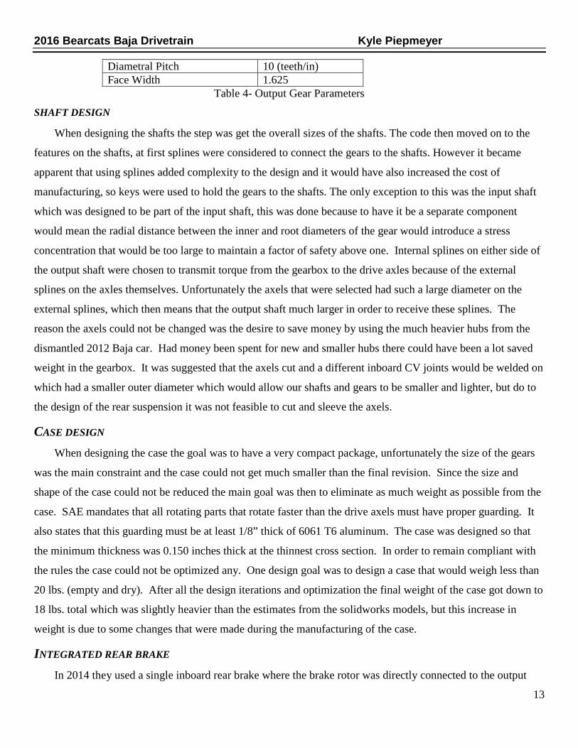
Table 4- Output Gear Parameters
SHAFT DESIGN When designing the shafts the step was get the overall sizes of the shafts. The code then moved on to the
features on the shafts, at first splines were considered to connect the gears to the shafts. However it became
apparent that using splines added complexity to the design and it would have also increased the cost of
manufacturing, so keys were used to hold the gears to the shafts. The only exception to this was the input shaft
which was designed to be part of the input shaft, this was done because to have it be a separate component
would mean the radial distance between the inner and root diameters of the gear would introduce a stress
concentration that would be too large to maintain a factor of safety above one. Internal splines on either side of
the output shaft were chosen to transmit torque from the gearbox to the drive axles because of the external
splines on the axles themselves. Unfortunately the axels that were selected had such a large diameter on the
external splines, which then means that the output shaft much larger in order to receive these splines. The
reason the axels could not be changed was the desire to save money by using the much heavier hubs from the
dismantled 2012 Baja car. Had money been spent for new and smaller hubs there could have been a lot saved
weight in the gearbox. It was suggested that the axels cut and a different inboard CV joints would be welded on
which had a smaller outer diameter which would allow our shafts and gears to be smaller and lighter, but do to
the design of the rear suspension it was not feasible to cut and sleeve the axels.
CASE DESIGN When designing the case the goal was to have a very compact package, unfortunately the size of the gears
was the main constraint and the case could not get much smaller than the final revision. Since the size and
shape of the case could not be reduced the main goal was then to eliminate as much weight as possible from the
case. SAE mandates that all rotating parts that rotate faster than the drive axels must have proper guarding. It
also states that this guarding must be at least 1/8” thick of 6061 T6 aluminum. The case was designed so that
the minimum thickness was 0.150 inches thick at the thinnest cross section. In order to remain compliant with
the rules the case could not be optimized any. One design goal was to design a case that would weigh less than
20 lbs. (empty and dry). After all the design iterations and optimization the final weight of the case got down to
18 lbs. total which was slightly heavier than the estimates from the solidworks models, but this increase in
weight is due to some changes that were made during the manufacturing of the case.
INTEGRATED REAR BRAKE In 2014 they used a single inboard rear brake where the brake rotor was directly connected to the output
13

2016 Bearcats Baja Drivetrain Kyle Piepmeyer
shaft. This design worked well, however when preforming maintenance on the case, the bolts that held the
caliper to the case were not in an easily accessible position. Ease of maintenance was a main focus for the
drivetrain team this year, so designing a rotor coupler and caliper mount so that all bolts were easily accessible
was a top priority and a significant improvement over last years design. It was decided to have the caliper bolt
to a bracket which was in turn bolted directly to the case. This design should give easier access to the caliper
and to the rotor in the event that they ever need to be quickly changed out.
Figure 10- Rear Brake Assembly
The above figure shows the integrated rear brake, the part that is red in the caliper mounting bracket which
gets bolted directly to the case, the green part is the rotor coupler this connects the rotor to the output shaft, and
the blue part is the rear rotor. When this setup was designed it was important that all the mounting bolts for the
caliper mount could be accessed and removed. This means that by removing the 4 grey bolts one can slide the
whole assembly off the output shaft without having to remove the caliper, then remove the rotor. This should
make the process of removing the gearbox easier and make replacing defective or damaged parts a lot easier.
OPTIMIZATION There were through several iterations before coming up with the most optimized design. In order optimize
each component Finite Element Analysis in Solidworks or ANSYS had to be run. Each component was
analyzed for the worst case situation to determine the viability of each design iteration. When running FEA on
the case the bearing loads that the matlab code produced were used in the simulation.
14

2016 Bearcats Baja Drivetrain Kyle Piepmeyer
Figure 11- Case FEA
In the figure above the maximum amount stress that was seen from the bearing loads was 2200 PSI of
stress on the bearing cup, 6061 –T6 has a yield strength of 40,000PSI, the resulting factor of safety is 18.5. This
factor of safety may seem very high but our goal was to design a more reliable and more robust gearbox, also
the design was limited by the rule set forth by SAE that all rotating parts that rotate faster than the drive axels
must have proper guarding. In order to comply with rule further optimization of the case was not possible.
Figure 12- Case Mount Worst Case FEA
15
2016 Bearcats Baja Drivetrain Kyle Piepmeyer
FEA also had to be run on the mounts that will hold the gearbox to the frame. In the figure it shows the
worst case scenario of stress, this simulation was a head on crash at top speed. It can be seen that most stress
that is seen is in the middle whole and it is 21700 PSI, this bracket is made out of 1/8 inch 4130 chromoly
which has a yield stress of 63100 PSI. The resulting factor of safety is 2.8 which may seem low, but it was
designed to be the weakest part, because the bolt would not shear off, or it could cause damage to the mounting
points on the aluminum case to be damaged. If this were a real life situation the steel bracket could deform but
the material would not fail, it would also not cause any damage to the case.
MANUFACTURING A main goal in the overall design of this gearbox when it came to the manufacturing of the components was
to keep everything simple so that it would reduce the cost and manufacturing lead times of the components.
When it came to the gears and shafts it was understood that the university’s machine shop did not have the
manufacturing knowledge or capability to make these components, so sponsorship packages were sent out to
machine shops and companies who could help us. After getting in contact with RPM Carbide Die Inc. and after
talking with them they graciously donated the material for the gears and shafts, the manufacturing of the gears
and shafts, and the heat treating for the gears and shafts. They used wire EDM machines to cut the teeth on the
gears and the internal spines on the output shaft and they used CNC controlled mill turn lathes to cut the shafts.
When designing the gearbox, it was always know that the university had CNC machines so the case designed so
that a machine could be programed to machine it in house at the university. Once the billets of aluminum came
in, Nicholas Plataniotis, a university staff member, was contacted. Nick helped program the CNC machine, and
would also advise on the best ways to machine each feature.
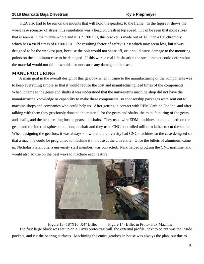
Figure 13- 18”X10”X4” Billet Figure 14- Billet in Proto-Trax Machine The first large block was set up on a 2 axis proto-trax mill, the external profile, next to be cut was the inside
pockets, and cut the bearing surfaces. Machining the entire gearbox in house was always the plan, but due to
16
2016 Bearcats Baja Drivetrain Kyle Piepmeyer
the limited hours the shop was open there was a possibility that it would not get completed in time. Hi-Tek
Manufacturing Inc. came forth with a sponsorship saying they would donate the manufacturing time and
complete the case. They had both halves of the case done in approximately 4 days, once the completed case
was received, the next step was to assemble the shafts by heating up the bearing and sliding them on the shafts,
after the shafts were assembled the two halves of the case were fitted together and bolted them shut.
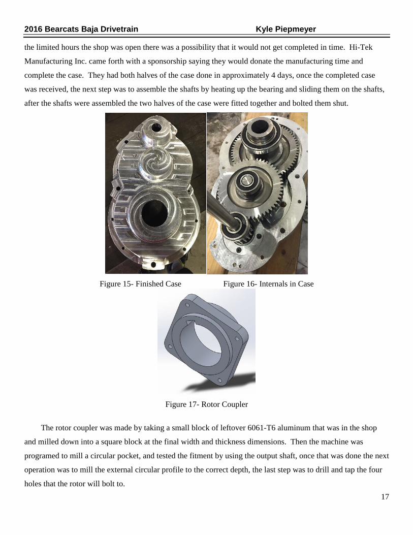
Figure 15- Finished Case Figure 16- Internals in Case
Figure 17- Rotor Coupler
The rotor coupler was made by taking a small block of leftover 6061-T6 aluminum that was in the shop
and milled down into a square block at the final width and thickness dimensions. Then the machine was
programed to mill a circular pocket, and tested the fitment by using the output shaft, once that was done the next
operation was to mill the external circular profile to the correct depth, the last step was to drill and tap the four
holes that the rotor will bolt to. 17

2016 Bearcats Baja Drivetrain Kyle Piepmeyer
Figure 18- Caliper Mount
When designed the caliper mounting bracket the original plan was to use the plasma-cam table on campus
to cut it out. But on the day it was to going to cut it out the plasma cutter was broken, so Nick offered to take
the material to his work and cut it out with the laser. The bracket is made from 1/4 inch thick 4130 steel. In
addition Nick also laser cut the 1/8 inch steel mounts that hold the gear box to the frame.
RESULTS WEIGHT GOALS For this year’s car one of the main goals was to eliminate as much weight as possible, one way to attempt to do
this was by eliminating reverse, this was done because theoretically the turning radius is small enough that there
was no need to use it at competition, it also added more complexity to the design of the transmission. In 2013
the entire drivetrain system weighed 128lbs. the 2014 cars drive train was 118 lbs. the goal for this year was to
have an overall weight of 108 lbs. for the drivetrain. However due to the size of some of the gears and shafts,
the overall subsystem weight was 120 lbs. Even though the target weight had been exceeded, the overall weight
was still almost as light as the 2014 subsystem, which given the size of our gears and shafts is a testament to
just how much weight was removed elsewhere in our subsystem. After closer inspection of the design there are
still several areas for weight improvements. Another goal of this project was to design a gearbox that will reach
a theoretical top speed of 40 mph. This target was set without taking into act resistance. At this point there is
no way to validate that the vehicle will reach its top speed, the only thing that can be done to validate the
design is to mount the engine and gearbox to a table and run it at full throttle and validate that all the
components will function as designed. The last goal was to improve the ease of maintenance, in order to
achieve this, the motor was mounted slightly higher on the frame, and this now means the gear box can be
removed easier and quicker
18

2016 Bearcats Baja Drivetrain Kyle Piepmeyer
BUDGET The budget for the drivetrain team was set to 8,000 dollars for this project. A lot of money was saved due to the
generous donations by companies to donate materials and manufacturing time. RPM Carbide Die Inc. really
helped by donating all the material for the gears and shafts, the manufacturing of the gears and shafts, and the
heat treating for the gears and shafts. Large billets of aluminum for the case were purchased, and after spending
weeks in the university’s machine shop, Hi-Tek came through with a sponsorship they were able to complete
both halves of the case for us in a very short amount of time. The bearings and dust seals were all donated by
Timken. With all the donations the only major components that were purchased were the CVT from Gaged
Engineering and the mounting hardware.
CONCLUSIONS The main goal of this entire project was to design a light weight, reliable gearbox, that was capable of 40 mph,
and that improved ease of maintenance. While the gearbox failed to meet the target weigh goal set forth for this
year’s team of 108lbs when the actual weigh was 120lbs, it maintain roughly the same weight as the 118lbs for
the 2014 car, the 2016 actually weighed less than the 2013 cars with 128lbs. The other goals at this point in
time cannot be validated due to the lack of a completed and running car. While this is not the most ideal
situation, there is still a way to verify that all components function as designed. The engine gearbox have been
bolted to a table and will be ran to max rpm as a proof of design. Improving the ease of maintenance was the
final design goal, the completion of this goal can be seen in the design of every component in the drivetrain.
For instance the bearing are all sealed bearing which will reduce the chance of dirt getting inside the bearings,
this should improve the life cycle of the bearing and subsequently decrease the frequency at which the bearing
have to be replaced. The integrated rear brake setup has easy maintenance designed in to each component, you
no longer have to take the caliper off in order to get the rotor off the output shaft, now you un bolt the caliper
mount and slide the whole assembly off the shaft.
ACKNOWLEDGEMENTS The completion of this project could not have been accomplished without the help and support of all the past
and present Bearcats Baja team members. The author would like to express the deepest thanks and appreciation
to all those involved from Hi-Tek Manufacturing, RPM Carbide Die, and Timken. Thanks and credit should
also be owed to Sean Hughes and Joseph Boggs for being excellent team mates and for doing a fantastic job on
the design of the gears and shafts. A very special thanks must be given to Nicholas Plataniotis who helped out
immensely with the machining of the case. Finally the team’s faculty advisor Dean Allen Arthur, deserves
special acknowledgement for being there to support us and offer his advice whenever we needed it during this
challenging project.
19
2016 Bearcats Baja Drivetrain Kyle Piepmeyer
WORKS CITED 1. Aaen, Olav. Olav Aaen's Clutch Tuning Handbook. Racine, WI: AAEN Performance, 1999. Print. 2. Budynas, Richard G., J. Keith. Nisbett, and Joseph Edward. Shigley. Shigley's Mechanical Engineering
Design. New York: McGraw-Hill, 2011. Print. 3. Kirtland, Dakota. 2014 Baja SAE Drivetrain. Rep. N.p.: U of Cincinnati, 2014. Print. 4. Mcausland, Michael, Michael Watkins, Ian Masterson, and Andrew Sommer. SAE Baja: Final Drive.
Rep. N.p.: California Polytechnic State U, 2010. Print. 5. Mott, Robert L. Machine Elements in Mechanical Design. Upper Saddle River, NJ: Pearson/Prentice
Hall, 2004. Print. 6. Schmidt, Marcus. Baja SAE International "Gearbox Design" Rep. N.p.: U of Cincinnati, 2014. Print.
Steele, Benjamin. 2013 University of Cincinnati Baja SAE Drivetrain. Rep. N.p.: U of Cincinnati, 2013. Print.
APPENDIX A
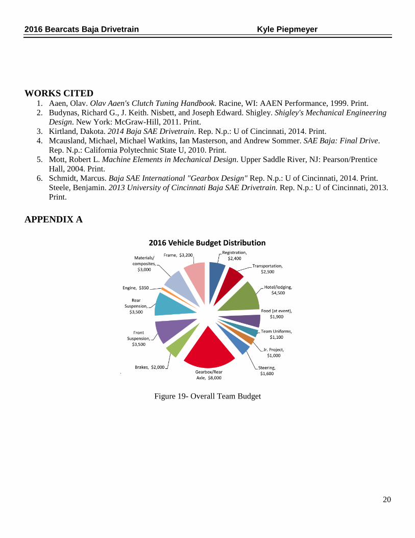
Figure 19- Overall Team Budget
20
2016 Bearcats Baja Drivetrain Kyle Piepmeyer
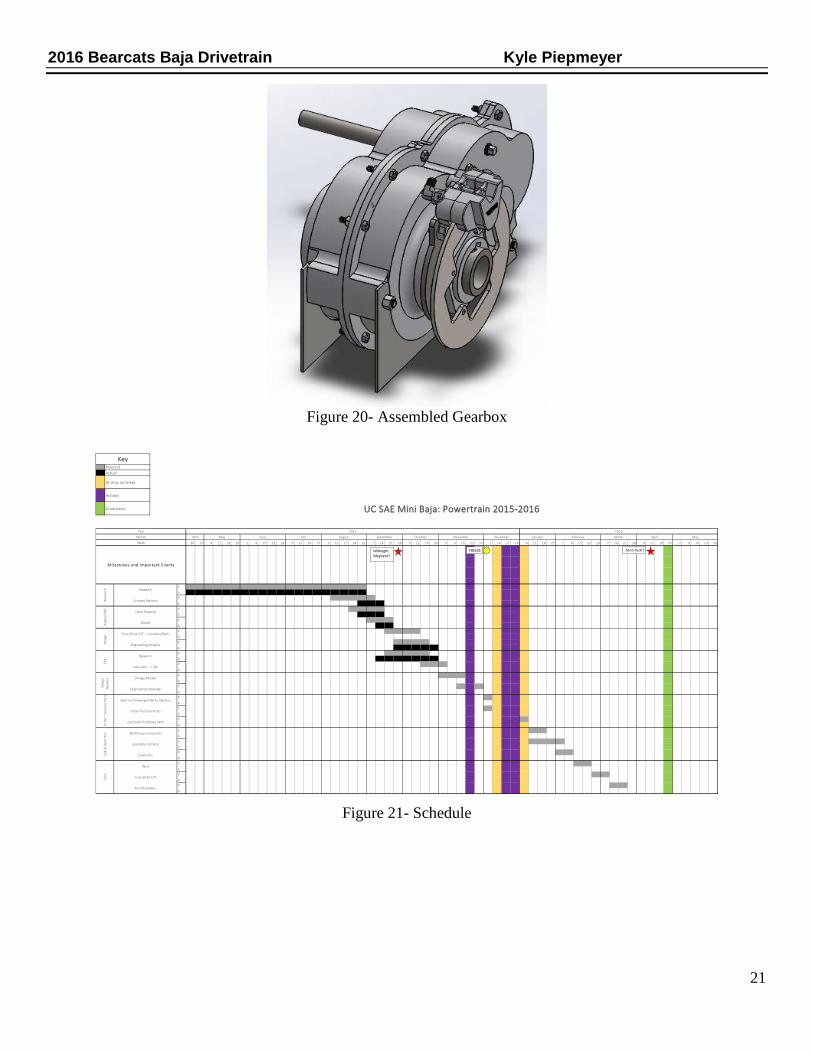
Figure 20- Assembled Gearbox
Figure 21- Schedule
20 27 4 11 18 25 1 8 15 22 29 6 13 20 27 3 10 17 24 31 7 14 21 28 5 12 19 26 2 9 16 23 30 7 14 21 28 4 11 18 25 1 8 15 22 29 7 14 21 28 4 11 18 25 2 9 16 23 30
P
A
P
A
P
A
P
A
P
A
P
A
P
A
P
A
P
A
P
A
P
A
P
A
P
A
P
A
P
A
P
A
P
A
P
A
P
A
Hand Drawing
Change Models
Fab
& A
ssem
ble
Test
Des
ign
Alph
a (C
AD)
Des
ign
Revi
sion
FEA
Ord
er /
Acq
uire
Par
ts
Final Assembly
Model
Engineering Drawings
Execution --> SW
2nd Order Purchase Parts
Check Fits
Order Purchase Parts
Tune 2014 CVT --> Gearbox Ratio
Assemble to frame
Tune 2016 CVT
Research
Send out Drawings/CAD to Vendors
Modify purchase parts
Dyno
Engineering Analysis
May
Week
Milestones and Important Events
October November December January February March
KeyPlannedActual
Holiday
At shop on break
Rese
arch Research
Concept Decision
Graduation UC SAE Mini Baja: Powertrain 2015-2016
Year 2015 2016
Month April May June July August September April
FREEZEMidnight Mayhem?
Tenn Tech?
21
2016 Bearcats Baja Drivetrain Kyle Piepmeyer
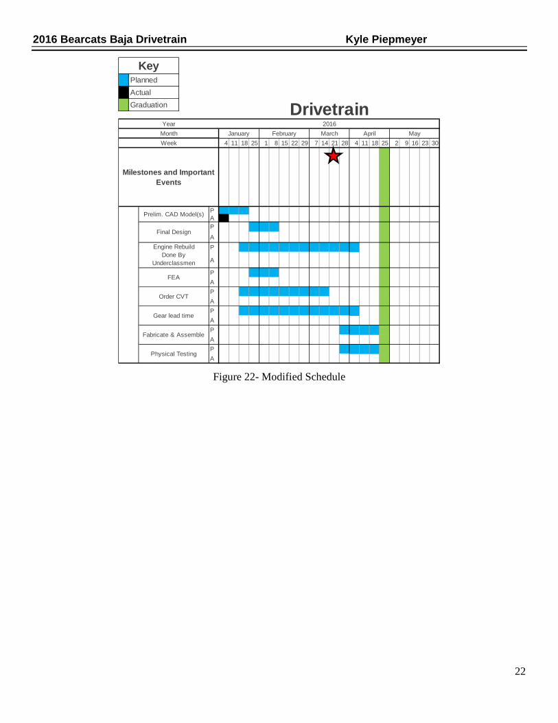
Figure 22- Modified Schedule
4 11 18 25 1 8 15 22 29 7 14 21 28 4 11 18 25 2 9 16 23 30
PAP
AP
A
PAPAPAPAPA
Drivetrain2016
April May
KeyPlannedActualGraduation
February MarchJanuary
Gear lead time
Fabricate & Assemble
Physical Testing
Year
WeekMonth
Prelim. CAD Model(s)
Final Design
FEA
Milestones and Important Events
Engine Rebuild Done By
Underclassmen
Order CVT
22

2016 Bearcats Baja Drivetrain Kyle Piepmeyer
APPENDIX B
Figure 23- Input Shaft FEA
23

2016 Bearcats Baja Drivetrain Kyle Piepmeyer
Figure 24- Intermediate Shaft FEA
24
2016 Bearcats Baja Drivetrain Kyle Piepmeyer
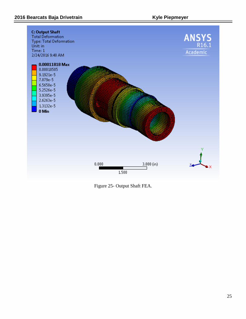
Figure 25- Output Shaft FEA.
25
2016 Bearcats Baja Drivetrain Kyle Piepmeyer
APPENDIX C
Figure 26- Intermediate Pinion Gear
26

2016 Bearcats Baja Drivetrain Kyle Piepmeyer
Figure 27- Intermediate Driven Gear
27
2016 Bearcats Baja Drivetrain Kyle Piepmeyer
Figure 28- Input Shaft
28

2016 Bearcats Baja Drivetrain Kyle Piepmeyer
Figure 29- Intermediate Shaft
29
2016 Bearcats Baja Drivetrain Kyle Piepmeyer
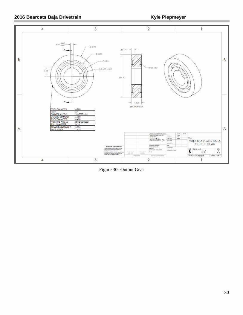
Figure 30- Output Gear
30
2016 Bearcats Baja Drivetrain Kyle Piepmeyer
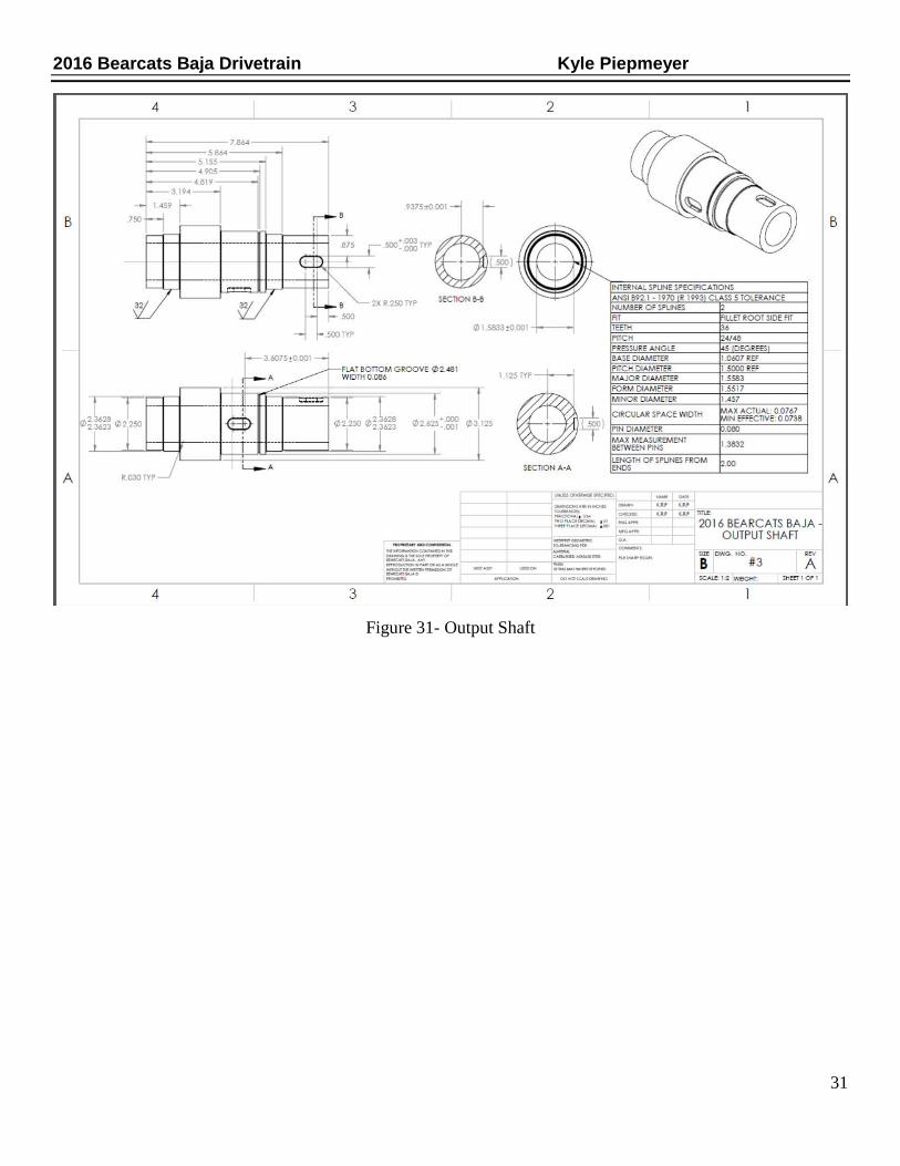
Figure 31- Output Shaft
31
2016 Bearcats Baja Drivetrain Kyle Piepmeyer
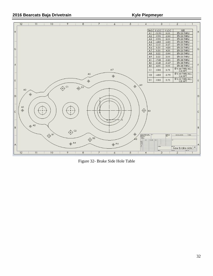
Figure 32- Brake Side Hole Table
32
2016 Bearcats Baja Drivetrain Kyle Piepmeyer
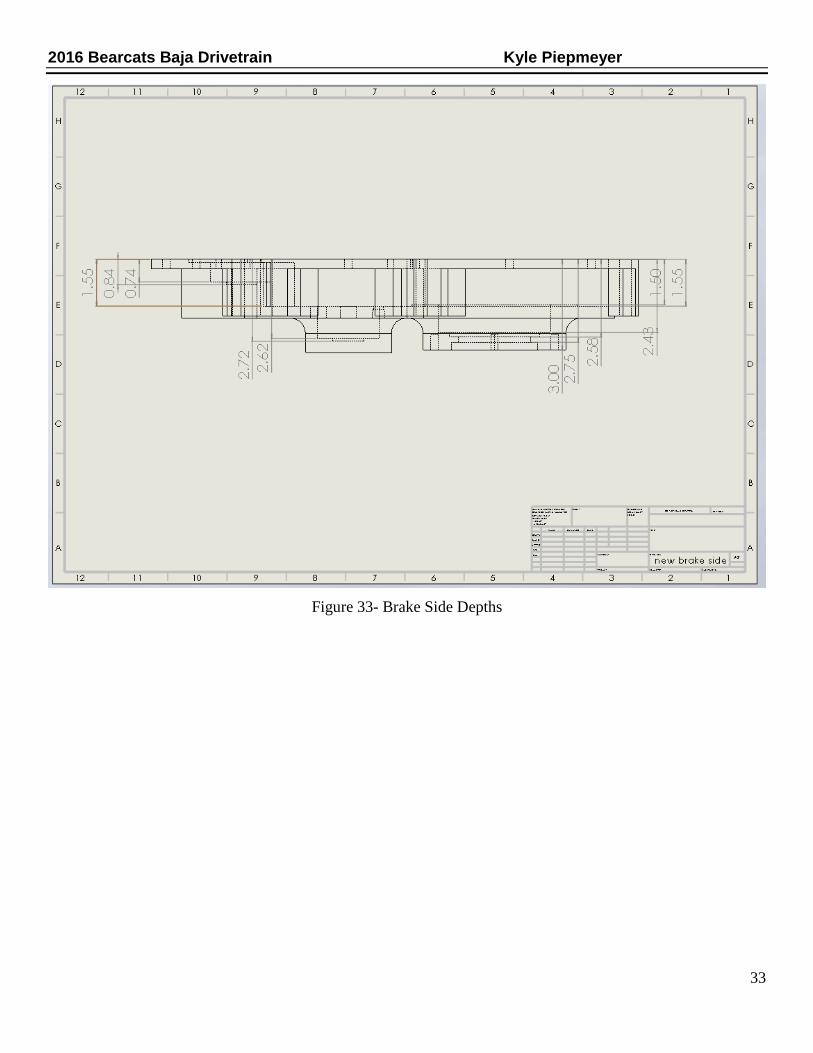
Figure 33- Brake Side Depths
33
2016 Bearcats Baja Drivetrain Kyle Piepmeyer
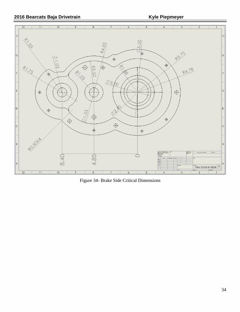
Figure 34- Brake Side Critical Dimensions
34
2016 Bearcats Baja Drivetrain Kyle Piepmeyer
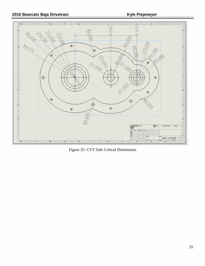
Figure 35- CVT Side Critical Dimensions
35

2016 Bearcats Baja Drivetrain Kyle Piepmeyer
Figure 36- CVT Side Depths
36

2016 Bearcats Baja Drivetrain Kyle Piepmeyer
Figure 37- CVT Side Hole Table
37