©2015 Moiz A Ezzy ALL RIGHTS RESERVED
74
©2015 Moiz A Ezzy ALL RIGHTS RESERVED
Transcript of ©2015 Moiz A Ezzy ALL RIGHTS RESERVED

©2015
Moiz A Ezzy
ALL RIGHTS RESERVED

[May 2015]
DESIGN AND TESTING OF EQUIPMENT FOR NON-DESTRUCTIVE
REHABILITATION OF BRIDGE DECK DELAMINATIONS
By
MOIZ ABBASBHAI EZZY
A thesis submitted to the
Graduate School-New Brunswick
Rutgers, The State University of New Jersey
in partial fulfillment of the requirements
for the degree of
Master of Science
Graduate Program in Mechanical and Aerospace Engineering
written under the direction of
Dr. Jingang Yi
and approved by
________________________
________________________
________________________
New Brunswick, New Jersey

ii
ABSTRACT OF THE THESIS
DESIGN AND TESTING OF EQUIPMENT FOR NON-DESTRUCTIVE
REHABILITATION OF BRIDGE DECK DELAMINATIONS
by MOIZ ABBASBHAI EZZY
Thesis Director:
Dr. Jingang Yi
Robots can perform accurate, fast, cheap and reliable repair and maintenance for
the country’s aging and deteriorating bridge decks. This thesis aims at developing a
small, robust and reliable drilling and material delivery unit to perform the Non-
Destructive Rehabilitation (NDR) for the Automated Non-Destructive Evaluation and
Rehabilitation System (ANDERS). The ANDERS NDR uses a Seekur robot as a platform
for the system and a Schunk robotic arm for the manipulation and precision. A modified
Bosch rotary hammer drill was used to perform minimal invasive drilling to reach the
defects through which alumino silicate matrix was pumped to repair and bond the
delamination. The scope of this thesis covers the design, machining and testing of the
complete robotic drilling and material delivery system. This system was thoroughly
tested for more than 300 cycles indoors and outdoors and even on deteriorated bridge
decks.
Testing of the drilling system showed that the current drill bit could not be used
for rehabilitation of delaminations smaller than 0.125 inches as the concrete dust clogged
the openings. Hence the second part of this thesis focuses on developing a new suction

iii
drill bit for drilling clean holes in delaminations. A 0.5 inch hollow suction drill bit was
completely designed, fabricated and tested as a part of this thesis. This drill bit used a
four carbide cutter, a carbon steel body and a HSS SDS Plus shank. It was meant to be
used in the same drilling unit developed earlier. The vacuum drill bit was successfully
tested on micro delaminations as small as 0.03 inches. A further use such as sampling
concrete is demonstrated using a prototype which can be applied to sampling rocks and
stone.

iv
ACKNOWLEDGEMENT
I would like to take this opportunity to offer my heartfelt thanks to all those in
who made my stay as graduate student very enjoyable and who made this work possible.
I am very grateful to my advisor, Dr. Jingang Yi. His guidance, sustained
encouragement and his work ethics have been a motivation throughout my graduate
studies. I would like to express my gratitude to Dr. Hae Chang Gea and Dr. Perumalsamy
N. Balaguru for taking time out of their schedules to be on my defense committee. I
would like to express my very great appreciation to Dr. Basily for his valuable and
constructive suggestions and his willingness to give his time so generously.
My thanks are given to my friends and colleagues who have contributed to
making my academic life at Rutgers enjoyable. I would like to express my very great
appreciation to my labmate Fei Liu for his help in all the testing and test setups, Mitja
Trkov for his valuable inputs and previous work on the topic, Pratul Singh for his advice
on various parts of the research, Anthony Ho for helping me out with machining some
parts and all the others that I have failed to mention for their constant support. Also I
would like to thank Mr. John Petrowski and Mr. Joseph Vanderveer for lending me a
helping hand when I needed one.
I would like to thank my siblings and my family Taher Saif, Dr. Rashida Saif,
Huzaifa Saif and Ruqaiyah Saif for being there and bearing with me. No
acknowledgment could possibly be complete without thanking my parents for their faith
in me and allowing me to be as ambitious as I wanted and my wife whose support,
encouragement, quiet patience and unwavering love was the driving force behind me.

v
TABLE OF CONTENTS
ABSTRACT OF THE THESIS .......................................................................................... ii
ACKNOWLEDGEMENT ................................................................................................. iv
TABLE OF CONTENTS .................................................................................................... v
LIST OF TABLES ............................................................................................................ vii
LIST OF FIGURES ......................................................................................................... viii
Chapter 1 INTRODUCTION .............................................................................................. 1
Chapter 2 AUTOMATED NON-DESTRUCTIVE EVALUATION AND
REHABILITATION SYSTEM (ANDERS)....................................................................... 6
2.1 Introduction ................................................................................................... 6
2.2 Nondestructive Rehabilitation System .......................................................... 8
Chapter 3 DEVELOPMENT OF ROBOTIC DRILLING AND DELIVERY UNIT ....... 10
3.1 Drill Selection ............................................................................................. 10
3.2 Drill Modification and Mounting................................................................ 11
3.3 Sensor Selection and Mounting .................................................................. 13
3.4 Material Development ................................................................................ 18
3.5 Design Considerations ................................................................................ 20
3.6 Pump & Tank Selection and Mounting ...................................................... 21
3.7 Seal Design ................................................................................................. 22
3.8 Testing......................................................................................................... 24

vi
Chapter 4 END-EFFECTOR ............................................................................................ 27
4.1 Initial Designs ............................................................................................. 27
4.2 Combination ................................................................................................ 29
4.3 Final End Effector ....................................................................................... 30
4.4 Reliability Test ............................................................................................ 33
4.5 Localization Test ......................................................................................... 36
Chapter 5 DRILL BIT DEVELOPMENT ........................................................................ 38
5.1 Introduction ................................................................................................. 38
5.2 Development ............................................................................................... 40
5.3 Version 1 ..................................................................................................... 40
5.4 Version 2 ..................................................................................................... 43
5.5 Drill Bit Testing .......................................................................................... 48
5.6 Sampling Unit ............................................................................................. 55
Chapter 6 CONCLUSION AND FUTURE WORK ......................................................... 58
6.1 Conclusion .................................................................................................. 58
6.2 Future Work ................................................................................................ 59
REFERENCES ................................................................................................................. 61

vii
LIST OF TABLES
Table 2-1 Novelties and Challenges in the NDR System ................................................... 9
Table 4-1 Problems and Solutions during Marathon Drilling Test................................... 35
Table 4-2 Results of Localization error ............................................................................ 37
Table 5-1 Improvements in the second version of the drill bit ......................................... 43

viii
LIST OF FIGURES
Figure 1-1 Core of a Bridge deck showing Delamination .................................................. 2
Figure 1-2 Current repair practices ..................................................................................... 2
Figure 2-1 Proposed ANDERS systems ............................................................................. 7
Figure 2-2 Cost of Rehabilitation of existing systems with ANDERS ............................... 8
Figure 3-1 Comparison of the two drills [4] ..................................................................... 11
Figure 3-2 Bosch Rotary Hammer Drill (RHH180-01) .................................................... 12
Figure 3-3 Assembly view of modified RHH180-01 [5] .................................................. 12
Figure 3-4 (a) 3D Printed Encoder Shaft Left (b) Final Modified Drill with the Encoder
Shaft mounted Right ......................................................................................................... 13
Figure 3-5 (a) US Digital E4P encoder [6] Left (b) Encoder mounts Right ..................... 14
Figure 3-6 Final Drill and Encoder mounting................................................................... 15
Figure 3-7 Computational result of Deformation of Drill Mount during drilling............. 16
Figure 3-8 ATI sensor mounting....................................................................................... 17
Figure 3-9 Mounting of all the sensors ............................................................................. 18
Figure 3-10: Diaphragm Pump Injection [9] .................................................................... 19
Figure 3-11: Flexural Strength [11] .................................................................................. 19
Figure 3-12: (a) Inorganic Left (b) Organic Right [9] ...................................................... 20
Figure 3-13: (a) Slant Shear Test Left (b) Direct Shear Test Right [9] ............................ 20
Figure 3-14: From left to right - Surface Mount with Zerk, Mechanical Packer and
Polyethylene Packer [9] .................................................................................................... 21
Figure 3-15 KNF’s Micro Diaphragm Pump .................................................................... 22

ix
Figure 3-16 First Seal........................................................................................................ 22
Figure 3-17 Right to Left: Cross-section of Oldest to Latest Geometries ........................ 23
Figure 3-18 Final Seal Geometry and Design ................................................................... 23
Figure 3-19 Final Seal Mold and Final Seal ..................................................................... 24
Figure 3-20 Material Delivery Testing ............................................................................. 24
Figure 3-21 Failed test ...................................................................................................... 25
Figure 3-22 Successful material delivery ......................................................................... 25
Figure 4-1 First three prototypes....................................................................................... 27
Figure 4-2 Prototypes with material delivery system ....................................................... 28
Figure 4-3 Screw rail ........................................................................................................ 29
Figure 4-4 Seal Mounting plate ........................................................................................ 30
Figure 4-5 Complete End-Effector ................................................................................... 31
Figure 4-6 Cover designed to protect the end-effector ..................................................... 32
Figure 4-7 ANDERS Non-Destructive Rehabilitation system ......................................... 33
Figure 4-8 356 holes drilled during the Marathon Reliability test .................................... 34
Figure 4-9 Drilling time for each hole during the Marathon Reliability test .................... 35
Figure 4-10 Localization test setup ................................................................................... 36
Figure 4-11 Localization error .......................................................................................... 37
Figure 5-1 Bosch drill with dust extraction kit [15] ......................................................... 38
Figure 5-2 Hollow bit with applied vacuum [14] ............................................................. 39
Figure 5-3 Hollow drill bit for lunar drilling [16]............................................................. 39
Figure 5-4 First Version of the Vacuum Drill Bit ............................................................. 41
Figure 5-5 Suction part in first version ............................................................................. 42

x
Figure 5-6 Failed Drill Bit Version 1 ................................................................................ 42
Figure 5-7 (a) Jig for Concentricity Left (b) Brazed Drill Bit Right ................................ 45
Figure 5-8 Drawing showing the Brazing and Machining of the Drill bit ........................ 46
Figure 5-9 Exploded view of the Final Version of the Drill Bit ....................................... 46
Figure 5-10 Final Version of the Vacuum Drill Bit with details ...................................... 47
Figure 5-11 Cross-section of the Final Version of the Vacuum Drill Bit showing details47
Figure 5-12 Drill Rig Design ............................................................................................ 49
Figure 5-13 Schematic diagram of the Drilling Test rig ................................................... 50
Figure 5-14 Penetration rate at different rpm Left Regular Drill Bit Right Vacuum Drill
Bit ...................................................................................................................................... 51
Figure 5-15 Comparison of penetration at 2950, 3950 and 5250 rpm .............................. 51
Figure 5-16 View of the 0.06” delamination. Left Regular drill Right Vacuum drill ...... 53
Figure 5-17 View of the 0.03” delamination drilled using Vacuum Drill bit ................... 54
Figure 5-18 Flow Simulation on the Final Version of the Drill Bit.................................. 55
Figure 5-19 Sampling Flow Chart .................................................................................... 56
Figure 5-20 Prototype Sampling Unit ............................................................................... 56
Figure 5-21 Setup of the sampling unit............................................................................. 57
Figure 5-22 Samples obtained from Vacuum Drill Bit ..................................................... 57
Figure 6-1 New Vacuum drill bit to be 3D printed from Stainless Steel .......................... 59

1
Chapter 1 INTRODUCTION
To ensure the transportation safety and economic growth of the country, the
condition of civil infrastructure such as bridges is of outmost importance. Similar to other
parts of infrastructure, the bridges age and deteriorate with time due to multiple factors.
Some of these factors include harsh climates, improper materials, rusting, excessive use
and inadequate and inefficient maintenance. [1] The Interstate 35W collapse in
Minnesota that happened in 2007 has been a wakeup call for the need of attention to the
aging bridges in the country. According to FHWA more than 20% of the US bridges are
over 50 years old; the service life they were designed for. This has led to an increase in
research in advanced technologies to detect, monitor and repair bridge. Therefore, repair,
rehabilitation and replacement of the deteriorating bridge components are extremely
important.
Defects such as delaminations are one of the serious deteriorations of bridge
decks. Delaminations are basically horizontal cracks in the concrete that occur mainly
due to rusting of steel rebars. The existence of delaminations reduces the strength of the
concrete significantly. As they normally have no any surface openings, it is very difficult
to detect and repair these delaminations. Figure 1-1 shows a core sample from a bridge
and these samples clearly demonstrate the delamination.

2
Figure 1-1 Core of a Bridge deck showing Delamination
Figure 1-2 Current repair practices
The state of the art practices of repairing delamination are also extremely high
cost and labor intensive. Figure 1-2 shows an example of the current practice to repair a
block of damaged bridge deck. The repair process is completely manual and involves
removing and then replacing the entire patch of damaged bridge deck.

3
From the above discussion the disadvantages of the current practice are
summarized as:
1. Completely manual operation and hence high cost and labor intensive
2. Time consuming and low efficiency as the repairing process involves replacing
the complete block of the bridge deck even if some portion of it is still in good
condition
3. Lane closures lasts for days and affects the daily traffic
4. Due to high cost of repair involved, the repair is conducted only in the final stages
of the deck deterioration
5. Safety hazard for field engineers working on the repair of the deck and that of the
drivers that pass by
It is therefore an urgent need to improve the bridge deck repairing efficiency and
safety while reducing the cost and negative impact on traffic. The use of robotics and
automation technologies has been increasingly effective in solving problems in
construction and civil infrastructures. In the recent two decades, a lot of applications of
mobile robots in construction and civil infrastructure are for bridge inspection and
maintenance for example, painting etc. These robotic systems provide an autonomous
and convenient mobile platform to automate the whole process and eliminate any
possibilities of human injuries and also a reduction of cost due to functioning in extreme
or hazardous conditions [2].
With the use of robotics and automation, we will be able to address all of the
above mentioned issues without human intervention. This was the reason for the

4
development of the Non-Destructive Rehabilitation system for Automated Non-
Destructive Evaluation and Rehabilitation System. We have worked towards delivering a
non-destructive, rapid, cost effective rehabilitation at an early stage of deterioration using
a minimally invasive robotic drilling into bridge decks, needed to reach the locations
where defects such as delamination initiate. Chapter 2 sheds some details on ANDERS,
its importance, its use and its four different systems. We then introduce the Non-
Destructive Rehabilitation system, its advantages, novelties and challenges that were
faced while developing it and its current status.
As an important part in developing the material delivery system, the selection of
the drilling machine, its modification played an important part. The design considerations
of the drilling unit, its evolution through different designs and concepts and the final
design are included in Chapter 3. Different sensors were needed for feedback control of
the autonomous drilling process. In this chapter, we also give an insight into the sensors
used and their selection procedure. The novel alumino silicate matrix developed to glue
the delaminations and its properties are discussed along with the design and development
of the material delivery unit. In order to automate the process, the existing material
delivery mounts cannot be used as it is too complicated to be integrated with the robotic
drilling / filling end-effector design. A simple and fool proof design was needed. The
different designs and materials of the surface seal for this purpose are also discussed. The
material delivery unit is then tested and its results discussed.
The origin of one end-effector and its design evolution and combination of
drilling and material delivery unit into one end-effector is discussed in Chapter 4. The
current version of the end-effector is shown and its working explained. The reliability of

5
the end-effector is tested and proven reliable with a rigorous marathon run of about 200
holes. The Localization accuracy and consistency of the NDR is tested on an actual
bridge and a few delaminations are drilled into and pumped with repair matrix.
When drilling into delaminations, it was noticed that the openings get clogged.
Therefore, we present a development of a new kind of hollow vacuum drill bit in Chapter
5. The drilled holes through delamination can be maintained as clear and clean by
sucking out the debris while the drill bit progresses inside the concrete deck. In this
chapter, we first review the literature on such drill bits and show the first prototype,
design considerations and development of the current hollow vacuum drill bit. It is then
tested against existing drill bits and on concrete blocks with artificial delaminations
which shows clean holes with delaminations as small as 0.03 inches.
In Chapter 7 we conclude this thesis by presenting the aim of our work our targets
and what we achieved. Improvements in the vacuum drill bit are suggested and the next
design discussed. Suggestions are made to decrease the performance gap between the
vacuum and traditional drill bit by the use of an inertial filter attached to an eductor. It is
recommended that a FEM be created to optimize and improve the performance of the
pseudo-seal.

6
Chapter 2 AUTOMATED NON-DESTRUCTIVE EVALUATION AND
REHABILITATION SYSTEM (ANDERS)
ANDERS is a university-industry joint venture supported by the National Institute
of Standards and Technology’s (NIST) Technology Innovation Program (TIP) and other
academic and industry partners. The goal of ANDERS is to revolutionize the manner in
which the bridge decks are assessed, monitored and rehabilitated in a more quick,
economic and effective way. The technology innovation has produced advancements in
multiple fields including civil, mechanical, electrical and material engineering.
2.1 Introduction
ANDERS is composed of four different systems which interact with each other.
They are:
1. Multi-Modal Nondestructive Evaluation (MM-NDE) System
2. Global Structural Assessment (GSA) System
3. Automated Structural Identification (Auto St-Id)
4. Nondestructive Rehabilitation (NDR) System
The MM-NDE system includes Ground Penetrating Radar (GPR), impact echo
and ultrasonic methods. It identifies and distinguishes localized defects like cracks and
delaminations at a very high resolution using wave propagation theories. The GSA
system catches the global structural features using experimental modal analysis and
detects any significant effects of deterioration on a bridge structure by impacting the
bridge deck at specific points. The MM-NDE and GSA systems give the inputs to the

7
Auto St-Id system which uses an innovative method which constructs, calibrates and
utilizes simulation based models to assess the overall structural vulnerability and
capacity. The MM-NDE system directly communicates with the NDR system and gives a
detailed damage and deterioration information which includes the 3D location and map of
the cracks and delaminations in the bridge deck. The NDR system uses robotics and
automation for precision and rapid delivery of novel inorganic composite of alkali
alumino-silicate matrices reinforced with nano/micro fibers for rapid, nondestructive
repair and rehabilitation of bridge decks.
A concept schematic of proposed ANDERS physical systems is shown in
Figure 2-1.
Figure 2-1 Proposed ANDERS systems

8
2.2 Nondestructive Rehabilitation System
The NDR system is composed of:
1. Material development unit
2. Material delivery unit.
This thesis focuses mainly on the material delivery unit. The use of robotic end-
effector discussed in detail in Chapter 3 and Chapter 4 enables the NDR system to deliver
rapid, nondestructive repair and rehabilitation of bridge decks.
The use of the NDR system will lead to a longer bridge deck life by implementing
early intervention and hence increase the current average of 20-25 years to about 50 years
of deck life. It will also reduce time cost and need for expert interpretation to implement
the advanced technologies for rehabilitation and repair. Figure 2-2 shows the comparison
of cost of rehabilitation of different systems to the degree of deterioration.
Figure 2-2 Cost of Rehabilitation of existing systems with ANDERS

9
The novelties introduced in the NDR system and their associated challenges are
mentioned in Table 2-1.
Table 2-1 Novelties and Challenges in the NDR System
Novelties Challenges
The new material matrix is durable, has
great bonding with concrete substrate and
can flow into thin delaminations with little
difficulties
While drilling the opening to the
delaminations were blocked by the drilling
dust due to which the material delivery is a
problem
First use of autonomous robots for bridge
deck rehabilitation
Automation of highly complex systems and
processes that currently demand expert
manual interaction
Use of a 5 DOF robotic manipulator on an
onmi-motion robot gives high flexibility
and agility
Design and control the mechanical system,
mobile robot and manipulator, which were
not reported in any literature, was a
complicated task

10
Chapter 3 DEVELOPMENT OF ROBOTIC DRILLING AND
DELIVERY UNIT
Concrete repair is done in two steps. The first is drilling up to the delamination
location. Concrete drilling unlike conventional drilling for metals deals with hard but
brittle material. Concrete or rocks are drilled using hammer drills which are of two types,
one is a regular hammer drill which has a simple mechanical component to passively
generate the vibratory motion of the drill bit and the other is a rotary hammer drill which
actively creates powerful impacts of the drill bit.
The second is to inject a repair material into these delaminations. Concrete repair
is usually done using polymer resins as repair material. These polymer resin materials are
normally not mechanically compatible with concrete substrate. The repairs where these
are used do not have the strength of concrete and deteriorate with time and hence they are
not completely successful. Moreover, due to high viscosity, pumping these repairing
materials into hairline cracks is very difficult and it could even worsen the situation.
3.1 Drill Selection
On comparing drilling time of these two types of hammer drills with various
thrust forces to drill an equally-sized hole, it was found that it takes much less time for
the rotary hammer drill than that for the regular hammer drill set. It is also observed that
the drilling time for the rotary hammer drill is independent with the applied thrust force,
while for the regular hammer drill a larger thrust force results in a shorter drilling time
(Figure 3-1). It is clear that the rotary hammer drill is the best choice for a fast drilling

11
process [3]. A compact, portable rotary hammer drill (model RHH180-01 from Bosch) is
used for the robotic drill design.
Figure 3-1 Comparison of the two drills [4]
The manipulator has a limited payload capacity and hence we want to reduce the
weight on the drilling unit and try to make it as compact as possible. We would like to
run the drill using force feedback so that we do not produce a lot of load on the
manipulator as well as the end-effector. Later it was planned to have an ultrasonic sensor
for measuring distance from the bridge deck surface as our tests showed that on slanted
decks we had troubles positioning the drilling unit and an accelerometer was added to
calculate the vibrations. As the impacts and drilling rate is governed by the rotation of the
drill chuck and is controlled by the motor, we wanted to measure the rotation speed of the
drill.
3.2 Drill Modification and Mounting
The Bosch rotary hammer drill is bulky and has many parts not required for
autonomous drilling on the manipulator. The actual drill is shown in Figure 3-2 and only

12
the necessary parts needed to mount the drill shown in the assembly view in Figure 3-3
are needed for the robotic end effector.
Figure 3-2 Bosch Rotary Hammer Drill (RHH180-01)
Figure 3-3 Assembly view of modified RHH180-01 [5]
In order to measure the rotation speed, a shaft was designed and 3D printed using
Stratsys µPrint in Acrylonitrile butadiene styrene (ABS) and attached to the back of the
motor (Figure 3-4 (b)). It is designed with the largest shaft diameter available for the

13
encoder and has a geometry that matches the back of the motor along with openings for
motor ventilation. The 3D printed shaft is shown in Figure 3-4 (a). The final drill with
minimum necessary size and weight with an encoder shaft is shown in Figure 3-4 (b).
Figure 3-4 (a) 3D Printed Encoder Shaft Left (b) Final Modified Drill with the
Encoder Shaft mounted Right
Many efforts were made to mount the drill and find a compact mounting of the
drill. Finally, a clamp style mounting was decided and the gearbox housing attached to
the motor, as shown in the Figure 3-4, was chosen as the mounting point.
3.3 Sensor Selection and Mounting
1. Encoder
The gear ratio between the motor to the chuck was determined to be 42:13. From
the previous tests using a friction wheel at the drill chuck, it was determined that the
maximum drilling rotation speed is about 6300-6500 rpm and hence the maximum
rotations speed of the motor would be about 21000 rpm. A digital encoder (from US
14
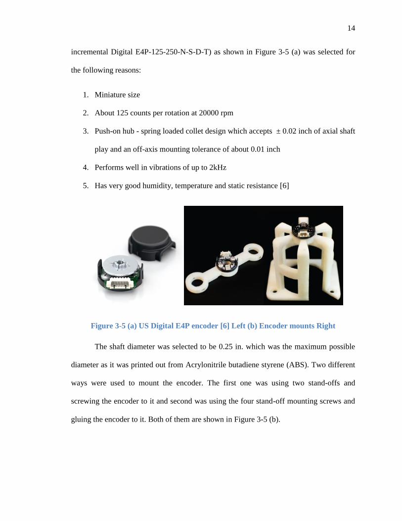
incremental Digital E4P-125-250-N-S-D-T) as shown in Figure 3-5 (a) was selected for
the following reasons:
1. Miniature size
2. About 125 counts per rotation at 20000 rpm
3. Push-on hub - spring loaded collet design which accepts ± 0.02 inch of axial shaft
play and an off-axis mounting tolerance of about 0.01 inch
4. Performs well in vibrations of up to 2kHz
5. Has very good humidity, temperature and static resistance [6]
Figure 3-5 (a) US Digital E4P encoder [6] Left (b) Encoder mounts Right
The shaft diameter was selected to be 0.25 in. which was the maximum possible
diameter as it was printed out from Acrylonitrile butadiene styrene (ABS). Two different
ways were used to mount the encoder. The first one was using two stand-offs and
screwing the encoder to it and second was using the four stand-off mounting screws and
gluing the encoder to it. Both of them are shown in Figure 3-5 (b).

15
The second method was preferred as it was fool-proof and did not depend on the
positional accuracy during mounting. The final mounting on the drill along with the
encoder is shown in the Figure 3-6.
Figure 3-6 Final Drill and Encoder mounting
2. Force-Torque Sensor
A force-torque sensor from ATI Industrial Automation (9105-TW-MINI45-ERA-
2.5) is selected due to the following reasons:
1. Compact size (ø1.8 in x 0.62 in) and weight (0.202 lb)
2. 240 lbf force range in z direction with a maximum allowable over load of ±2300
lbf
3. Resonant frequency of about 5600 Hz
4. High signal to noise ratio due to silicon strain gauges [7]

16
We chose to mount the sensor with its z-axis parallel to the drilling axis as the
range of the force and sensitivity is higher in the z-direction. Aircraft grade Aluminum
alloy 7075 is selected to reduce weight and provide higher resistance to bending. The
thickness of 0.5 in is selected based on simulations (Figure 3-7) to reduce deformation. It
can be seen that the maximum deformation is about 0.01mm.
Figure 3-7 Computational result of Deformation of Drill Mount during drilling
Figure 3-8 shows the ATI mounted on the back on the drill with its z axis parallel
to the drilling axis.

17
Figure 3-8 ATI sensor mounting
3. Other Sensors
Honeywell’s 943-F4Y-2D-1C0-300E is an industrial sensor with 3.9 in to 31.4 in
scanning distance. It is small, has a good seal and is chemical resistance [8] and hence it
was selected. It is needed to be mounted facing down while drilling and hence it was
mounted on the drill mount as shown in Figure 3-9.

18
Figure 3-9 Mounting of all the sensors
The accelerometer selected was from PCB Piezotronics (608A11). It is small
(9/16 in. x 2 in.) and light (3.5 oz.), has a measurement range of ±50g and a frequency
range of 0.5 Hz to 10,000 Hz. It is mounted by a 1/4-28 stud besides the ultrasonic sensor
as can be seen from the Figure 3-9.
3.4 Material Development
The ANDERS material development team identified that the nano/micro
inorganic composites for rapid, non-destructive repair of thin delaminations was
successful using alkali alumino-silicate matrices reinforced with nano/micro fibers [9].
They demonstrated that certain mixes of these gave a material with good mechanical
properties and had desired flow for the hair-line cracks as thin as 0.03 inches [10].
Figure 3-10 shows the mix flowing easily through a micro crack in one of their
experiments.
19
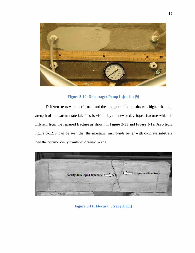
Figure 3-10: Diaphragm Pump Injection [9]
Different tests were performed and the strength of the repairs was higher than the
strength of the parent material. This is visible by the newly developed fracture which is
different from the repaired fracture as shown in Figure 3-11 and Figure 3-12. Also from
Figure 3-12, it can be seen that the inorganic mix bonds better with concrete substrate
than the commercially available organic mixes.
Figure 3-11: Flexural Strength [11]

20
Figure 3-12: (a) Inorganic Left (b) Organic Right [9]
Figure 3-13: (a) Slant Shear Test Left (b) Direct Shear Test Right [9]
Figure 3-13 shows the slant shear test result and direct shear test setup. The direct
shear strength of 575 psi was observed which is almost the same of concrete and the slant
shear or bonding strength of the inorganic matrix is around 3500 psi which is comparable
to commercially available organic repair material.
3.5 Design Considerations
The ANDERS material development team used several methods to inject the
material into cracks. They tried letting the material flow under its own head and with a
vacuum applied at the end, hand driven piston and a diaphragm based positive

21
displacement pump as seen in Figure 3-10. From extensive experiments, it was proved
that the diaphragm pump worked better than the other methods. For the cracks they tested
different commercial available mechanical fixtures as shown in Figure 3-14 which all had
complicated installation procedures and also required attaching injection probes to the
fixtures. In order to automate the process, this process had to be changed, simplified and
minimized to fit the end-effector design.
Figure 3-14: From left to right - Surface Mount with Zerk, Mechanical Packer and
Polyethylene Packer [9]
3.6 Pump & Tank Selection and Mounting
The KNF’s micro diaphragm liquid pump (model no. UNF1.25RPDC B-4A)
which is based on the principle of the oscillating displacement pump and was selected
(Figure 3-15). The pump delivers maximum 300 ml/min and can operate at max 87 psi
pressure. It has self-priming suction of about 8.86" Hg and can run dry and is extremely
chemical resistant. It fulfills all the considerations taken such as:
1. It had to be small and light for robotic mounting
2. It had to be a positive displacement type diaphragm pump
3. More than 75 psi of maximum available pressure
4. Self-Priming capability along with capability of running dry for short period

22
5. Resistant to the highly alkaline alumino-silicate matrix
Figure 3-15 KNF’s Micro Diaphragm Pump
The tank to store the matrix is actually an oil reservoir which has aluminum top
and bottom plates around a clear plastic bowl and a self-closing fill cap. This tank is the
perfect size and is mounted behind the manipulator using pipe mounts. The pump
mounting was designed using the pump geometry and pump was mounted above the tank
to minimize the distance between the pump and the tank and hence reducing the pressure
drop.
3.7 Seal Design
As mentioned above, using the mechanical fixtures was not an option but the hole
had to be sealed when the matrix was pumped into the cracks. At first a polyurethane seal
was used as shown in the Figure 3-16 below.
Figure 3-16 First Seal

23
This seal did not give acceptable results; hence a pseudo-seal was designed based
on the concept of vacuum cups. Being molded from an elastomer material, it could not be
simulated to optimize the shape; hence a trial and error method was applied. The design
was improved through the 5 different designs the cross sections of which can be seen in
Figure 3-17 below.
Figure 3-17 Right to Left: Cross-section of Oldest to Latest Geometries
Each of the above shown geometries was tried in one to three different materials
before the final geometry and material was finalized. The final seal geometry is as shown
in the Figure 3-18 below.
Figure 3-18 Final Seal Geometry and Design

24
The final design was molded using silicone shore A40 which performed better
than polyurethane shore A20 and A40, Silicone shore A55 and A25 and an acrylic
polymer named Tango Black from Objet Connex 3D printer. The mold was 3D printed to
get the exact geometry using Stratsys µPrint. The Figure 3-19 shows the mold and the
seal that was finally used.
Figure 3-19 Final Seal Mold and Final Seal
3.8 Testing
The material delivery unit was initially tested using water on a solid block of
concrete with a gap representing a delamination. Testing of the first material delivery
system is shown below. We had leaks from the side of the seal as shown in Figure 3-20
and it resulted in the development of a newer seal.
Figure 3-20 Material Delivery Testing

25
Figure 3-21 Failed test
Figure 3-22 Successful material delivery
Later we tested the material delivery unit on artificial delaminations of 0.06
inches. The probability of a successfully delivering the material was 0.53 which means
about one in every two holes was unsuccessful. The way it was tested was we drilled a
few relief holes and if the matrix came out of any of these holes it was a successful test
and if it leaked from the sides on the seal it was unsuccessful. Figure 3-21 shows one of

26
the failed test where the water is leaking from the sides of the seal. Figure 3-22 shows
one of the few successful tests where the matrix is coming out of the other holes. The
hole on the right side in Figure 3-22 is of an unsuccessful test where the hole was
clogged. This lead to the development of the vacuum drill bit.

27
Chapter 4 END-EFFECTOR
The Drilling unit and the Material Delivery unit was put together to create the
End-Effector. During the proposal the plan was to have a separate drilling unit and a
separate material delivery unit controlled by two robotic manipulators. But as the project
progressed we felt that it was simpler and more intuitive to have the whole system as one.
The following are the advantages of doing so:
1. Less power consumption by using just one manipulator
2. Less complex computing to avoid obstacles when only one arm is operating
3. Less sensors and computing for image processing for hole detection
4. Simple flip around system for material delivery
4.1 Initial Designs
Figure 4-1 First three prototypes
28
Several designs and prototypes were created before the current prototype.
Figure 4-1 shows the first three prototypes that were designed and tested. The disc above
the drilling unit is a force-torque sensor. The first and second prototypes use a lead screw
and two guides with linear bearings for feeding the drill. The third prototype design uses
a simpler screw rail with a single screw and a guide all in one. This makes the complete
design lighter and compact. The first prototype uses a motor and gears it down for the
feed, the second and third just use a coupling. The drill mounting was welded and was
quite complicated to assemble.
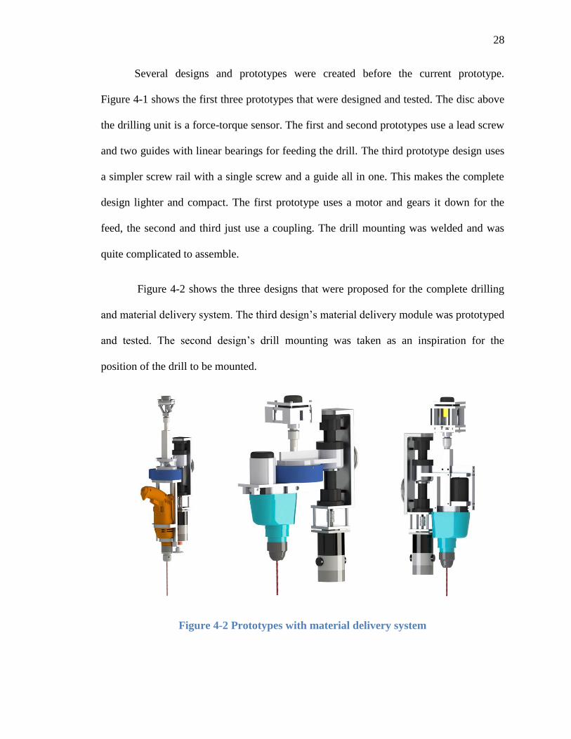
Figure 4-2 shows the three designs that were proposed for the complete drilling
and material delivery system. The third design’s material delivery module was prototyped
and tested. The second design’s drill mounting was taken as an inspiration for the
position of the drill to be mounted.
Figure 4-2 Prototypes with material delivery system
29
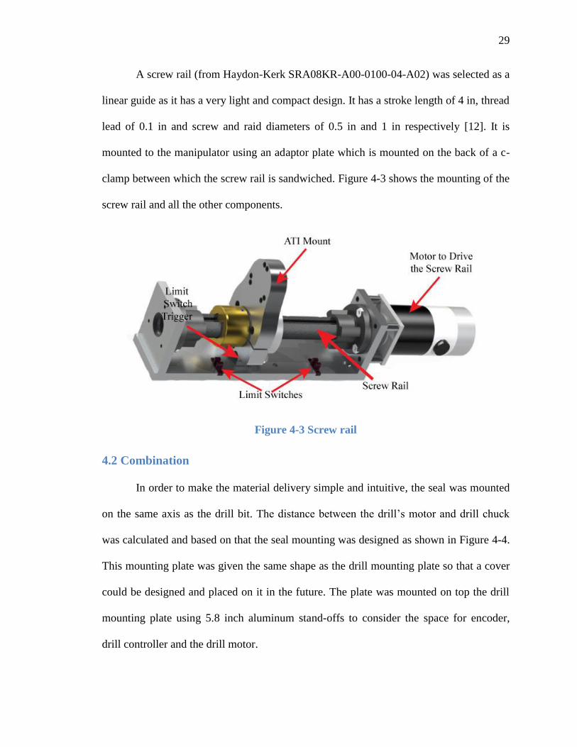
A screw rail (from Haydon-Kerk SRA08KR-A00-0100-04-A02) was selected as a
linear guide as it has a very light and compact design. It has a stroke length of 4 in, thread
lead of 0.1 in and screw and raid diameters of 0.5 in and 1 in respectively [12]. It is
mounted to the manipulator using an adaptor plate which is mounted on the back of a c-
clamp between which the screw rail is sandwiched. Figure 4-3 shows the mounting of the
screw rail and all the other components.
Figure 4-3 Screw rail
4.2 Combination
In order to make the material delivery simple and intuitive, the seal was mounted
on the same axis as the drill bit. The distance between the drill’s motor and drill chuck
was calculated and based on that the seal mounting was designed as shown in Figure 4-4.
This mounting plate was given the same shape as the drill mounting plate so that a cover
could be designed and placed on it in the future. The plate was mounted on top the drill
mounting plate using 5.8 inch aluminum stand-offs to consider the space for encoder,
drill controller and the drill motor.

30
Figure 4-4 Seal Mounting plate
The drill controller was initially mounted inside the robot but we faced some
noise issues due to the long wiring and hence we had to place it as close to the drill as
possible. The controller was mounted using industrial velcro and mounted besides the
material delivery valve as shown in Figure 4-4.
4.3 Final End Effector
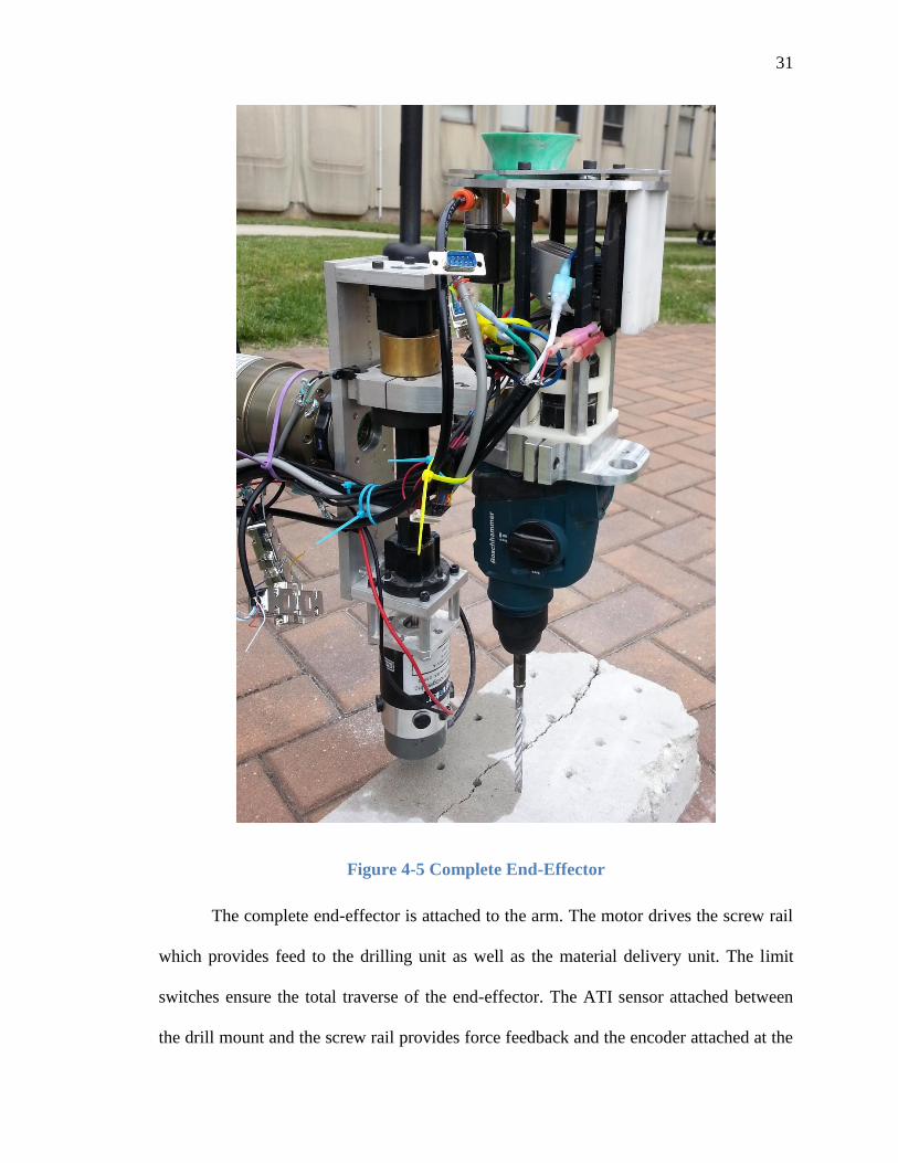
The final version of the complete end-effector is shown in Figure 4-5.
31
Figure 4-5 Complete End-Effector
The complete end-effector is attached to the arm. The motor drives the screw rail
which provides feed to the drilling unit as well as the material delivery unit. The limit
switches ensure the total traverse of the end-effector. The ATI sensor attached between
the drill mount and the screw rail provides force feedback and the encoder attached at the
32
back of the drill’s motor provides the rotation speed of the drill and the impact of the
hammer. The last joint of the manipulator is rotated 1800 to deliver the material. The seal
provides a good seal and the solenoid valve provides immediate start and stop and hence
avoids leakages.
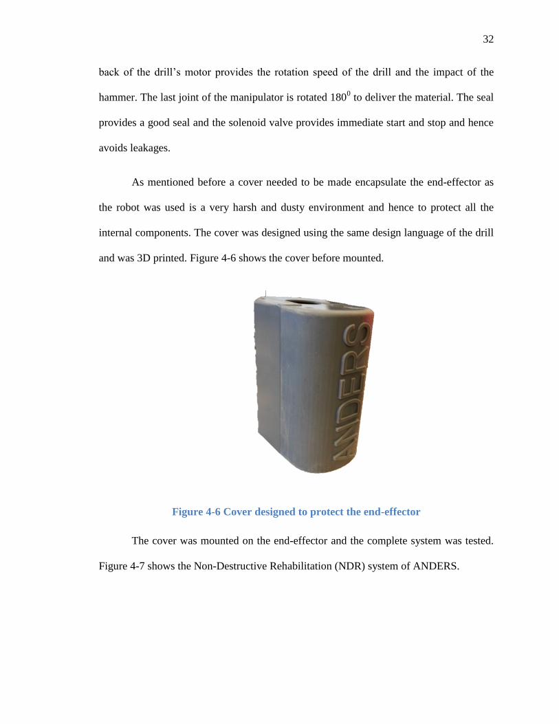
As mentioned before a cover needed to be made encapsulate the end-effector as
the robot was used is a very harsh and dusty environment and hence to protect all the
internal components. The cover was designed using the same design language of the drill
and was 3D printed. Figure 4-6 shows the cover before mounted.
Figure 4-6 Cover designed to protect the end-effector
The cover was mounted on the end-effector and the complete system was tested.
Figure 4-7 shows the Non-Destructive Rehabilitation (NDR) system of ANDERS.

33
Figure 4-7 ANDERS Non-Destructive Rehabilitation system
4.4 Reliability Test
Once the preliminary parts of the end-effector were tested individually, the
reliability of the end-effector unit was tested rigorously using a marathon test of more
than three hundred holes. The objective of this run was to have an idea of all the causes
of interruptions and improve upon them. This was an indoor test due to the amount of
time it would take.
4.4.1 Test Setup
The Schunk manipulator was programmed to drill 72 holes on 2 blocks of 20 in. x
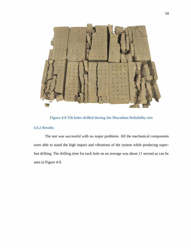
8 in. x 4in. Each hole was drilled 5 cm apart. Figure 4-8 shows all the 356 holes that were
drilled on the 10 blocks.
34
Figure 4-8 356 holes drilled during the Marathon Reliability test
4.4.2 Results
The test was successful with no major problems. All the mechanical components
were able to stand the high impact and vibrations of the system while producing super-
fast drilling. The drilling time for each hole on an average was about 11 second as can be
seen in Figure 4-9.

35
Figure 4-9 Drilling time for each hole during the Marathon Reliability test
Although the test was mostly successful we did face a few minor problems which
were solved on the spot and we didn’t face the same problem again. The problems faced
during the test and the solutions applied to solve the problems are mentioned in
Table 4-1.
Table 4-1 Problems and Solutions during Marathon Drilling Test
Problems Solutions
Loose wiring The wires were securely attached to the end-effector
Controller over-heating Switching on the air-conditioner (not a major problem as

36
most of the actual tests would be done outside with good air
flow and a decent time gap compared to our current test)
4.5 Localization Test
The precision in delivering minimal invasive robotic rehabilitation is tested using
the complete robotic system along with its navigational properties using the test setup
shown in Figure 4-10. Eight blocks were placed 450 apart on a circle of diameter
approximately 20m. Their GPS position was taken and conveyed to the robot via wifi.
Figure 4-10 Localization test setup
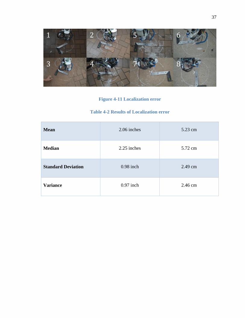
Photographs were taken just before the drilling was performed. Figure 4-11 shows
these eight photographs. The circles shown are 14 inches in diameter (35.56cm).
Table 4-2 shows the results of the test.
37
Figure 4-11 Localization error
Table 4-2 Results of Localization error
Mean 2.06 inches 5.23 cm
Median 2.25 inches 5.72 cm
Standard Deviation 0.98 inch 2.49 cm
Variance 0.97 inch 2.46 cm

38
Chapter 5 DRILL BIT DEVELOPMENT
Bridge deck rehabilitation as mentioned earlier requires drilling up to the
locations where delamination initiates. Due to the percussive action while drilling into
delamination and the brittleness of concrete (becomes powder), it was noticed that the
openings into these cracks get clogged and repair material cannot be delivered. Many
other similar developments have faced similar issues while dealing with the problem [9]
[13] [14]. Hence it is desirable that no drilling powder is left to remain in the crack.
5.1 Introduction
Different systems have been developed to remove the concrete dust produced
during drilling. A powerful vacuum attached to a dust extraction kit like the one in
Figure 5-1 doesn’t work all the time for holes with such a small diameter [9].
Figure 5-1 Bosch drill with dust extraction kit [15]
Whereas a hollow bit with vacuum applied as the one shown in Figure 5-2
performs much better at removing the debris and concrete powder [14]. Though this
method to embed a carbide tip in the drill shaft can only be applied while using a 2
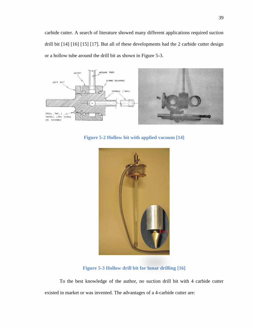
39
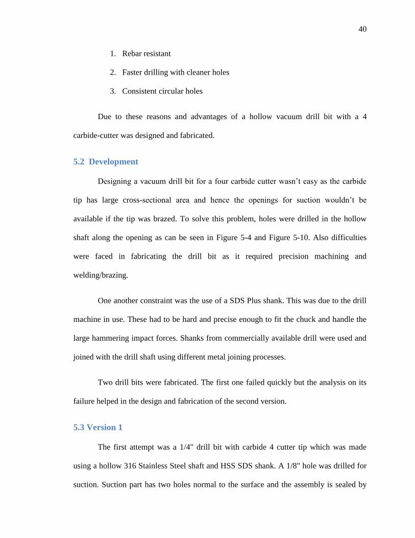
carbide cutter. A search of literature showed many different applications required suction
drill bit [14] [16] [15] [17]. But all of these developments had the 2 carbide cutter design
or a hollow tube around the drill bit as shown in Figure 5-3.
Figure 5-2 Hollow bit with applied vacuum [14]
Figure 5-3 Hollow drill bit for lunar drilling [16]
To the best knowledge of the author, no suction drill bit with 4 carbide cutter
existed in market or was invented. The advantages of a 4-carbide cutter are:
40
1. Rebar resistant
2. Faster drilling with cleaner holes
3. Consistent circular holes
Due to these reasons and advantages of a hollow vacuum drill bit with a 4
carbide-cutter was designed and fabricated.
5.2 Development
Designing a vacuum drill bit for a four carbide cutter wasn’t easy as the carbide
tip has large cross-sectional area and hence the openings for suction wouldn’t be
available if the tip was brazed. To solve this problem, holes were drilled in the hollow
shaft along the opening as can be seen in Figure 5-4 and Figure 5-10. Also difficulties
were faced in fabricating the drill bit as it required precision machining and
welding/brazing.
One another constraint was the use of a SDS Plus shank. This was due to the drill
machine in use. These had to be hard and precise enough to fit the chuck and handle the
large hammering impact forces. Shanks from commercially available drill were used and
joined with the drill shaft using different metal joining processes.
Two drill bits were fabricated. The first one failed quickly but the analysis on its
failure helped in the design and fabrication of the second version.
5.3 Version 1
The first attempt was a 1/4" drill bit with carbide 4 cutter tip which was made
using a hollow 316 Stainless Steel shaft and HSS SDS shank. A 1/8" hole was drilled for
suction. Suction part has two holes normal to the surface and the assembly is sealed by
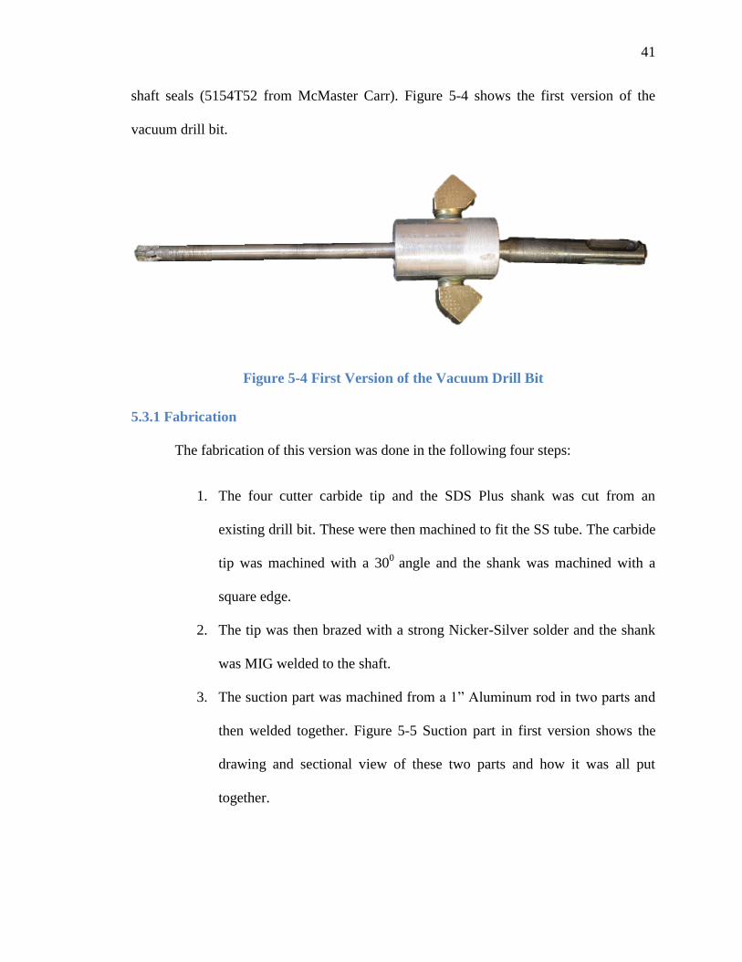
41
shaft seals (5154T52 from McMaster Carr). Figure 5-4 shows the first version of the
vacuum drill bit.
Figure 5-4 First Version of the Vacuum Drill Bit
5.3.1 Fabrication
The fabrication of this version was done in the following four steps:
1. The four cutter carbide tip and the SDS Plus shank was cut from an
existing drill bit. These were then machined to fit the SS tube. The carbide
tip was machined with a 300
angle and the shank was machined with a
square edge.
2. The tip was then brazed with a strong Nicker-Silver solder and the shank
was MIG welded to the shaft.
3. The suction part was machined from a 1” Aluminum rod in two parts and
then welded together. Figure 5-5 Suction part in first version shows the
drawing and sectional view of these two parts and how it was all put
together.
42
Figure 5-5 Suction part in first version
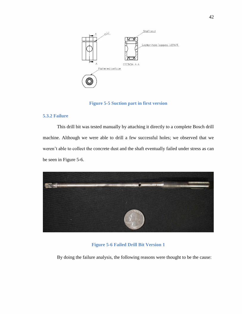
5.3.2 Failure
This drill bit was tested manually by attaching it directly to a complete Bosch drill
machine. Although we were able to drill a few successful holes; we observed that we
weren’t able to collect the concrete dust and the shaft eventually failed under stress as can
be seen in Figure 5-6.
Figure 5-6 Failed Drill Bit Version 1
By doing the failure analysis, the following reasons were thought to be the cause:

43
1. Masonry bits are usually made using soft materials but hard tips. The SS316 bit
used for the shaft is hard but brittle material and hence cannot dissipate the impact
energy well.
2. Very little suction due to the small (1/8") suction hole. Also the hole drilled was
normal to the shaft which is not streamlined and hence creates a large pressure
drop.
3. Due to the high stresses during rotation and impact, the stress concentration took
place at the hole for suction on the drill.
4. Welding was used to join the HSS shank to SS shaft. The distortion resulted in
non-concentricity of the 3 axes.
5. Shaft seals did not perform as expected. They provide decent seal but created high
friction while rotating.
5.4 Version 2
Based on the observations and lessons learned from the first version of the
vacuum drill bit; the second version was designed taking into consideration all the
problems. Table 5-1 below shows all the improvements made in the second version of the
drill bit based on the problems that were faced during the first prototype.
Table 5-1 Improvements in the second version of the drill bit
Problem Improvements
Hard, brittle and thin shaft Non brittle carbon steel was used with a larger
diameter (0.5")

44
Very little suction Two streamlined holes (Figure 5-11) for higher and
easier flow were drilled at the suction part. The shaft
of drill bit was milled and ground in streamlined flutes
(Figure 5-8, Figure 5-10) for easier flow at the tip. A
pump with high flow (2.5 cfm) was selected to
produce higher flow of the material.
Stress Concentration Suction holes were created at a larger diameter (3/4")
than the shank to prevent stress concentration.
Welding Distortion Brazing with a strong solder (Ni-Ag) was used to join
metals instead of welding. Also a jig as shown in
Figure 5-7 was created to maintain concentricity while
brazing.
Shaft Seals – Ineffective Sealed bearings (6384K790 from McMaster Carr)
were used instead of shaft seals which were very
smooth and provided sufficient seal (Figure 5-10).
45
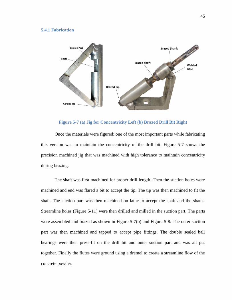
5.4.1 Fabrication
Figure 5-7 (a) Jig for Concentricity Left (b) Brazed Drill Bit Right
Once the materials were figured; one of the most important parts while fabricating
this version was to maintain the concentricity of the drill bit. Figure 5-7 shows the
precision machined jig that was machined with high tolerance to maintain concentricity
during brazing.
The shaft was first machined for proper drill length. Then the suction holes were
machined and end was flared a bit to accept the tip. The tip was then machined to fit the
shaft. The suction part was then machined on lathe to accept the shaft and the shank.
Streamline holes (Figure 5-11) were then drilled and milled in the suction part. The parts
were assembled and brazed as shown in Figure 5-7(b) and Figure 5-8. The outer suction
part was then machined and tapped to accept pipe fittings. The double sealed ball
bearings were then press-fit on the drill bit and outer suction part and was all put
together. Finally the flutes were ground using a dremel to create a streamline flow of the
concrete powder.

46
Figure 5-8 Drawing showing the Brazing and Machining of the Drill bit
The assembly view of the drill as shown from the render in Figure 5-9 shows how
each part was put together.
Figure 5-9 Exploded view of the Final Version of the Drill Bit
The Final assembly of the drill is shown in Figure 5-10.

47
Figure 5-10 Final Version of the Vacuum Drill Bit with details
Figure 5-11 is a CAD render of the cross-section of the drill to show the internal
details of the drill.
Figure 5-11 Cross-section of the Final Version of the Vacuum Drill Bit showing
details

48
Using this drill bit we were able to drill successful holes and also drill
successfully in artificial delaminations. The results are discussed in detail later in this
chapter.
5.5 Drill Bit Testing
5.5.1 Test Rig Setup
The drill and the drilling unit were initially tested on an indoor test rig which was
designed as shown in Figure 5-12. The setup is similar to the one used in [4]. A cable
potentiometer from Celesco Inc. (SP1-25) was used to measure the drilling depth and
ATI mini 45 and US Digital E4P were used to measure the drilling forces and rotation
speed respectively. The entire assembly glides on vertical linear guides which are rigidly
attached to the wall. The thrust force is controlled by adding counter-weights using a
pulley system.

49
Figure 5-12 Drill Rig Design
Real-time xPC Target from Mathworks is used for data acquisition and control
systems design. The xPC Target system consists of a slave computer that is running the
xPC Target real-time kernel and a host computer running Matlab/Simulink. A data
acquisition card from National Instruments (PCI-6221) is installed on the slave computer.
The communication between the slave and the host computers is through the high-speed
ethernet. The drilling speed is controlled by Simulink and the sensor outputs from xPC
are saved with time stamps by Matlab command on host computer. The Schematic of the
Test rig is shown in the Figure 5-13 below.

50
Figure 5-13 Schematic diagram of the Drilling Test rig
5.5.2 On Concrete blocks
The first round of testing was done on regular concrete blocks to measure the
drilling performance. In order to get comparable results, a clean filter (in case of
the vacuum drill bit) and a fully charged battery was used all the time. Figure 5-14
shows the graph of penetration in cm versus the time in second using the regular
drill bit and the vacuum drill bit that was developed. As it can be seen that at full
throttle (6400 rpm), the drill was bouncing off the concrete block and the results
were not satisfactory. It can be seen that with increase in speed increases the
penetration rate for both the drill bit.

51
Figure 5-14 Penetration rate at different rpm Left Regular Drill Bit Right Vacuum
Drill Bit
Figure 5-15 Comparison of penetration at 2950, 3950 and 5250 rpm

52
The comparison between the two drill bits at the same speed is shown in
Figure 5-15. It can be seen that at 2950 rpm, both the drill have comparable penetration
rate but at higher speeds the penetration rate of the regular drill bit is higher. The analysis
of the results shows that the vacuum drill bit is unable to remove the concrete powder as
fast as it was produced at higher speeds due to the lower flow rate of the current vacuum
pump. So hence forth we will be doing the tests at 2950 rpm. Although multiple tests
were performed; data was logged for only one speed per drill bit. The results were in-line
with assumptions and hence we moved to the next tests on the artificial delamination.
5.5.3 On Blocks with Artificial Delamination
Once the vacuum drill was tested and compared with regular drill bit, the next
step was to test the vacuum drill bit for the purpose it was designed for that is to drill in
delaminations. Artificial delaminations were created using patio blocks that were 2 inches
high. Two different colored blocks were used to clearly identify the delamination. The
first test was done using a 0.06 inch (~1.5 mm) shim and the blocks were glued using
liquid nails. The results obtained from using regular drill bit and the vacuum drill bit are
shown in Figure 5-16 below.

53
Figure 5-16 View of the 0.06” delamination. Left Regular drill Right Vacuum drill
It can be seen that the delamination drilled using the regular drill bit on the left is
clogged with concrete dust where as the one drilled using the vacuum drill bit as shown
on the right is clean.
Once the tests on 0.06 inch delamination were successful samples with a
delamination of 0.03 inches (~0.76 mm) were made and again we had successful clean
delaminations as shown in Figure 5-17 below.
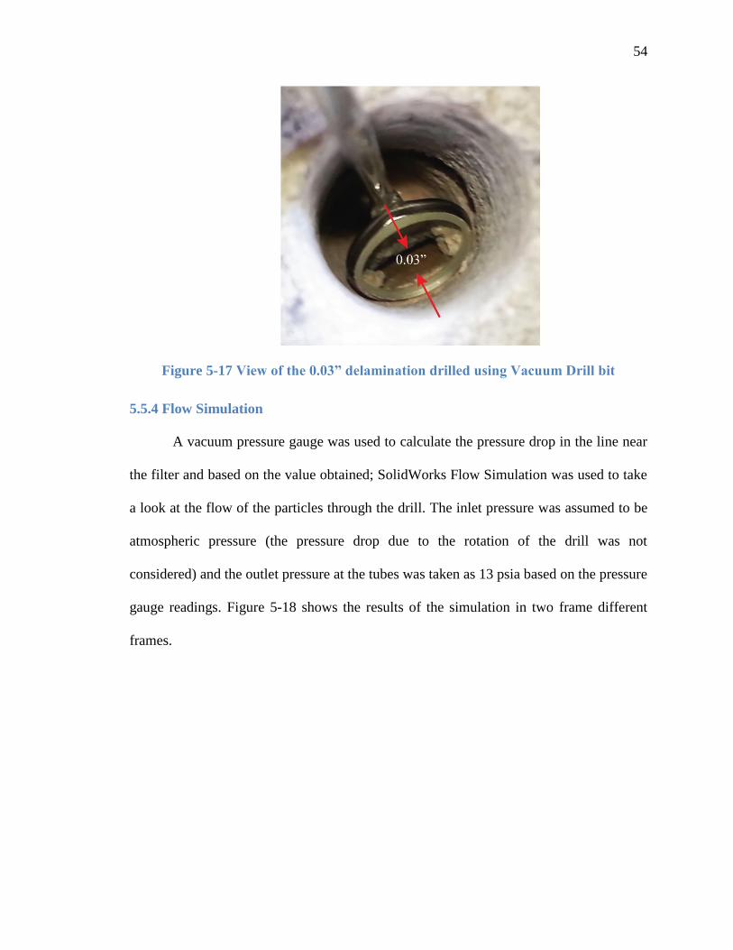
54
Figure 5-17 View of the 0.03” delamination drilled using Vacuum Drill bit
5.5.4 Flow Simulation
A vacuum pressure gauge was used to calculate the pressure drop in the line near
the filter and based on the value obtained; SolidWorks Flow Simulation was used to take
a look at the flow of the particles through the drill. The inlet pressure was assumed to be
atmospheric pressure (the pressure drop due to the rotation of the drill was not
considered) and the outlet pressure at the tubes was taken as 13 psia based on the pressure
gauge readings. Figure 5-18 shows the results of the simulation in two frame different
frames.

55
Figure 5-18 Flow Simulation on the Final Version of the Drill Bit
This shows that when the suction holes are not in-line, the velocity drops
significantly. Hence it is preferable not to have holes on both, the drill and the suction
part 1800 apart so that the frequency of at least one hole lining up with suction in higher
and gives a better flow. Figure 6-1 shows the suggested design which addresses this
issue.
5.6 Sampling Unit
The developed drill bit can also be used for taking and storing samples from
concrete and or rock expeditions. The figure below shows the working logic of the
sampling unit.
56
Figure 5-19 Sampling Flow Chart
There would be a series of manifolds as required not just three. The reservoir is to
collect the extra stuff not required to be saved for sampling which can be dumped later.
The idea was tested by designing a sampling unit as shown below which for the
prototyping purpose was 3D printed and contained an acrylic tube with a filter inside the
tube.
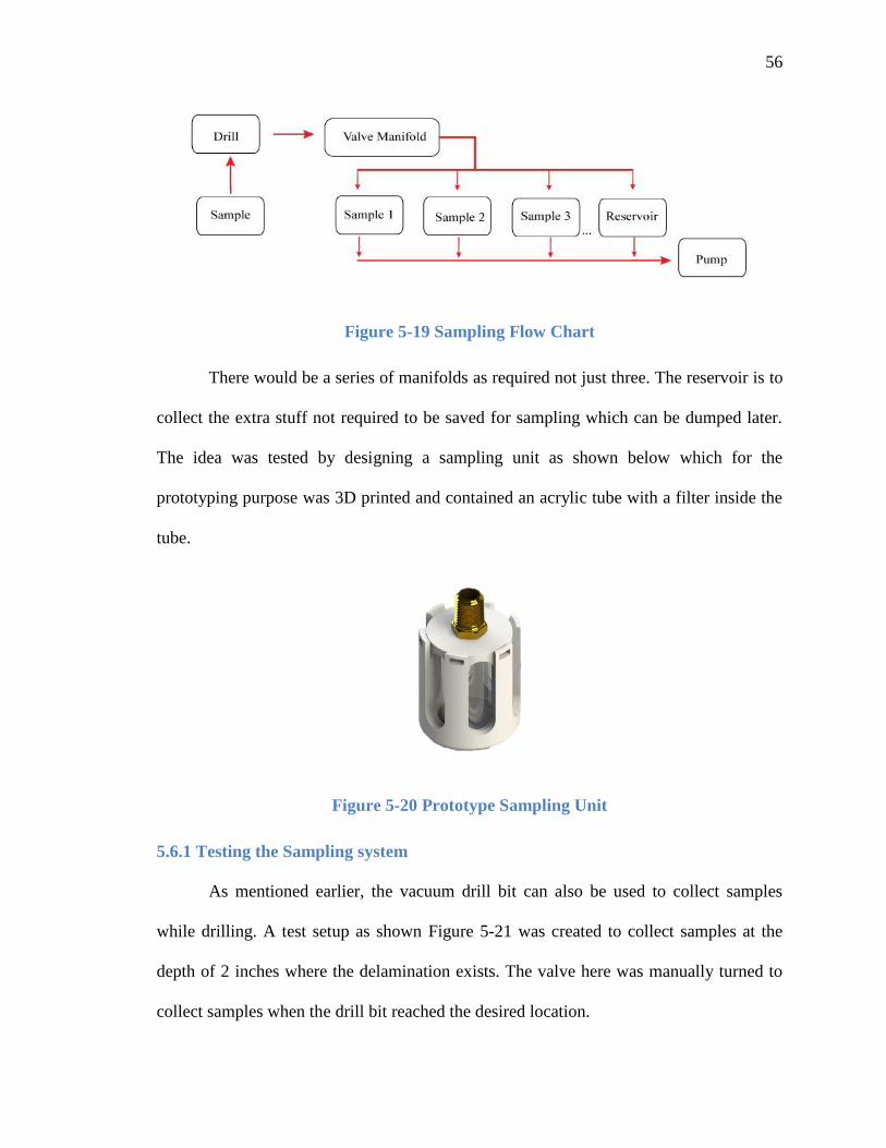
Figure 5-20 Prototype Sampling Unit
5.6.1 Testing the Sampling system
As mentioned earlier, the vacuum drill bit can also be used to collect samples
while drilling. A test setup as shown Figure 5-21 was created to collect samples at the
depth of 2 inches where the delamination exists. The valve here was manually turned to
collect samples when the drill bit reached the desired location.

57
Figure 5-21 Setup of the sampling unit
5.6.2 Results
The resulting samples obtained from the tests are shown in Figure 5-22. The result
shows that the drill can be used for the purpose of sampling at different locations and
could be used by geologists and civil engineers. The civil engineers could use the
samples to test the chlorine content at an exact GPS location.
Figure 5-22 Samples obtained from Vacuum Drill Bit

58
Chapter 6 CONCLUSION AND FUTURE WORK
6.1 Conclusion
The aim of this thesis was to develop material delivery system for the non-
destructive rehabilitation system to rehabilitate old and deteriorated bridges. Bosch
rotary hammer drill was selected to perform fast and minimal invasive drilling and then
modified to measure the drilling speed and mount it on a robotic manipulator. Force-
Torque sensor, accelerometer, ultrasonic sensor, digital encoder and limit switches were
attached to control the position and operation of the drill using a closed loop feedback.
The material delivery system was designed behind the drill machine and a diaphragm
pump was used to deliver the matrix. After testing the first seal a pseudo-seal was
designed and its design was tried in different material to get the best geometry and
material combination. The drilling and material delivery units were combined into one
end-effector which was thoroughly tested for reliability, outdoor drilling and material
delivery.
The material delivery testing showed a flaw in the system and a detailed study of
existing literature led to the development of a new for carbide-cutter hollow vacuum drill
bit. A concept was prototyped and improved upon. A final version was fabricated and
tested on solid concrete blocks and bocks with artificial delaminations of different sizes.
It was found that with the given equipment, both the regular and vacuum drill bit had
similar performance at 2950 rpm. The vacuum drill bit was also able to drill clean holes
in delaminations as small as 0.03 inches (approximately 0.76mm). A simulation of flow
shows scope of improvement in the design.

59
To conclude the work presented here can be used for fast, accurate and precise
robotic rehabilitation for bridge decks with large delaminations. The vacuum drill-bit
developed can be used to rehabilitate bridge deck defects with micro-delaminations and
can also be used for sampling concrete, rocks and soil. Such an autonomous system can
be used to detect chlorine content and hence the quality of concrete, collect samples from
different locations in places humans cannot reach (such as high altitudes, interstellar
missions etc.).
6.2 Future Work
The comparison of drilling performance at different speeds as shown in
Figure 5-15, the flow simulation as discussed in 5.5.4 and the design process of seal 5.5.4
are some of the things that can be improved upon.
6.2.1 Drill Bit
The current vacuum drill bit design involves machining and joining of a lot of
parts which results in it being difficult to manufacture. It would be much more accurate
and robust and also easier if it were 3D printed or investment casted and then heat-
treated.
Figure 6-1 New Vacuum drill bit to be 3D printed from Stainless Steel
The Figure 6-1 above shows the drill without the carbide tip. The advantages of
this design are:

60
1. The flutes at the end are precise and are twisted for smooth flow
2. Problems that arose from multi-part drill like concentricity of axes will be
avoided.
3. 3 suction holes are completely streamlined and hence smoother flow. This would
also take into consideration the flow problems as discussed in 5.5.4
4. Roller bearings will be used which is mounted on the shaft of the drill bit and this
will make the complete assembly much thinner and last longer.
6.2.2 Filter and Vacuum Pump
A particulate filter was currently used which had to be emptied out after each hole
due to the excessive amount of concrete dust produced during the process. Instead of a
large filter an inertial filter could be used which doesn’t store the particulates. This could
be coupled with an eductor to get higher flow-rate. The air for the eductor can be
supplied by a regulated aluminum air tank.
6.2.3 Seal
A Finite Element Model should be created to optimize the geometry, softness and
material of the pseudo-seal. This would ensure the perfect amount of vacuum to be
created in the cavity based of the force that can be applied and hence provide better
sealing than can be currently offered.

61
REFERENCES
[1] K. P. Chong, N. J. Carino and G. Washer, "Health monitoring of civil
infrastructures," Smart Materials and Structures Vol. 12, pp. 483-493, 2003.
[2] H. La, R. Lim, B. Basily, N. Gucunski, J. Yi, A. Maher, F. Romero and H.
Parvardeh, "Autonomous robotic system for high-efficiency non-destructive
bridge deck inspection and evaluation," in Proc. IEEE Conf. Automat. Sci. Eng.,
Madison, WI.
[3] F. Liu, M. Trkov, J. Yi and N. Gucunski, "Modeling of Pure Percussive Drilling
for Autonomous Robotic Bridge Decks Rehabilitation," in CASE, 2013.
[4] M. Trkov, F. Liu, J. Yi and H. Baruh, "Study of concrete drilling for automated
non-destructive evaluation and rehabilitation system for bridge decks," in Proc.
SPIE 7983, Nondestructive Characterization for Composite Materials, Aerospace
Engineering, Civil Infrastructure, and Homeland Security 2011, 798307, San
Diego, CA, 2011.
[5] "Bosch RHH180-01 Parts," Toolspart Pro, [Online]. Available:
http://www.toolpartspro.com/bosch-parts/bosch-rhh180-01-parts.html.
[6] US Digital, [Online]. Available: http://www.usdigital.com/products/e4p.
[Accessed 2 May 2013].
[7] "ATI Force/Torque Sensor: Mini 45," ATI Industrial Automation, [Online].

62
Available: https://www.ati-ia.com/products/ft/ft_models.aspx?id=Mini45.
[Accessed 2012 January 2012].
[8] "Honeywell SC Portal," Honeywell Sensing and Control, [Online]. Available:
http://www.honeywellscportal.com//index.php?ci_id=3108&la_id=1&pr_id=311
18.
[9] M. Klein, Nondestructive repair and rehablitation of structural elements using
high strength inorganic polymer composites (Dissertation), New Brunswick, NJ:
Rutgers, The State University of New Jersey, 2013.
[10] M. Klein, G. Venkiteela, H. Najm and P. Balaguru, "Nanoscale materials for non-
destructive repair of transportation infrastructures," in SPIE, San Diego, 2011.
[11] G. Venkiteela, M. Klein, H. Najm and P. Balaguru, "Evaluation of nano/micro
composites for nondestructive repair of delaminated structures," in SPIE, San
Diego, 2012.
[12] Haydon Kerk Motion Solutions, [Online]. Available:
http://www.haydonkerk.com/LinearActuatorProducts/LinearRailsGuidesSplines/
ScrewRailLinearActuators/SRASRZSelectorCharts/tabid/269/Default.aspx.
[13] M. G. Pattengill, C. F. Crumpton and G. A. McCaskill, "Spot Treatment of
Hollow Areas by Rebonding with Injected Epoxy Resin," State Highway
Commission of Kansas, Topeka, Kansas, 1969.

63
[14] F. W. Stratton and B. F. McCollom, "Repair of hollow or softened areas in bridge
decks by rebonding with injected epoxy resins or other polymers," State Highway
Commission of Kansas, Topeka, Kansas, 1974.
[15] S. Shepherd, S. R. Woskie, C. Holcroft and M. Ellenbecker, "Reducing silica and
dust exposures in construction during use of powdered concrete-cutting hand
tools: efficacy of local exhaust ventilation on hammer drills," Journal of
Occupational and Enviromental Hygiene, vol. 6, pp. 42-51, 2009.
[16] J. Fabwald, N. I. Komle, M. S. Bentley and P. Weiss, "Considerations on a
suction drill for lunar surface drilling and sampling: II. experimental tests in
vacuum conditions," Acta Geotechnica, vol. 7, pp. 115-127, 2012.
[17] M. G. Kesterson and J. A. DeLand, "Vacuum Drilling System". United States
Patent US 7,563,060 B2, 21 July 2009.