2014 NDIA Tech Demo Multifaceted Gun Fluid Flow Modeling ...
16
2014 NDIA Tech Demo Multifaceted Gun Fluid Flow Modeling and Experimentation at ARDEC Name: Robert Carson Laurie Florio Daniel Cler Presenter: Anthony Cannone Date: 14 May 2014
Transcript of 2014 NDIA Tech Demo Multifaceted Gun Fluid Flow Modeling ...

2014 NDIA Tech Demo
Multifaceted Gun Fluid Flow Modeling
and Experimentation at ARDEC
Name: Robert Carson
Laurie Florio
Daniel Cler
Presenter: Anthony Cannone
Date: 14 May 2014
2
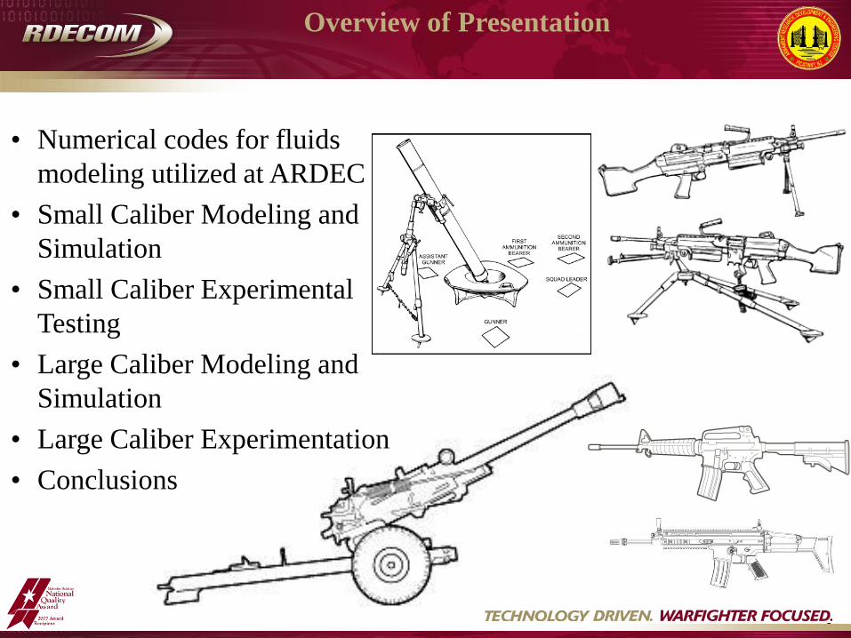
• Numerical codes for fluids
modeling utilized at ARDEC
• Small Caliber Modeling and
Simulation
• Small Caliber Experimental
Testing
• Large Caliber Modeling and
Simulation
• Large Caliber Experimentation
• Conclusions
Overview of Presentation

3
Arbitrary Lagrangian-Eulerian 3D
multiphysics code was developed by
Lawrence Livermore National
Laboratory.
Finite Element Based.
Explicit time integration with non
reactive flows.
Compressible Navier-Stokes equations
were solved on an unstructured
quadrilateral mesh.
Two step process: • Lagrangian
• Advection/remap
Advancing variables at the mesh nodes,
and then updating element variables
based on the new node variable values.
Fluids Modeling ALE3D
1. Calculate the time increment Δtn.
2. Construct a force at each mesh node.
3. Compute the acceleration at each mesh
node.
4. Compute the new velocity at each
mesh node.
5. Compute the new position at each
mesh node.
6. Update various element variables based
on node variables advanced to tn+1.
7. Calculate new artificial viscosity in
Qn+1each element.
8. Apply material model properties based
on material, volume, etc. in each
element.
9. Compute time constraints which will
be applied when Δtn+1 is calculated for
the next step.
4
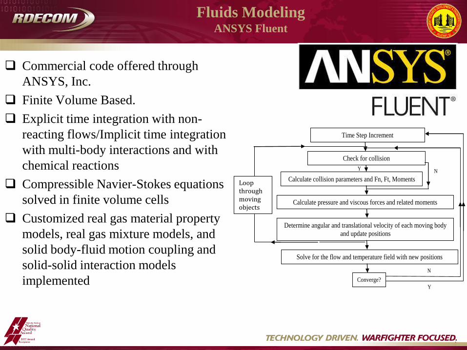
Commercial code offered through
ANSYS, Inc.
Finite Volume Based.
Explicit time integration with non-
reacting flows/Implicit time integration
with multi-body interactions and with
chemical reactions
Compressible Navier-Stokes equations
solved in finite volume cells
Customized real gas material property
models, real gas mixture models, and
solid body-fluid motion coupling and
solid-solid interaction models
implemented
Fluids Modeling ANSYS Fluent
Figure 2: Algorithm Flow Chart
Time Step Increment
Check for collision
Calculate collision parameters and Fn, Ft, Moments
Y N
Calculate pressure and viscous forces and related moments
Determine angular and translational velocity of each moving body
and update positions
Solve for the flow and temperature field with new positions
Converge? Y
N
Loop through moving objects
5
Small Caliber Modeling and Simulation
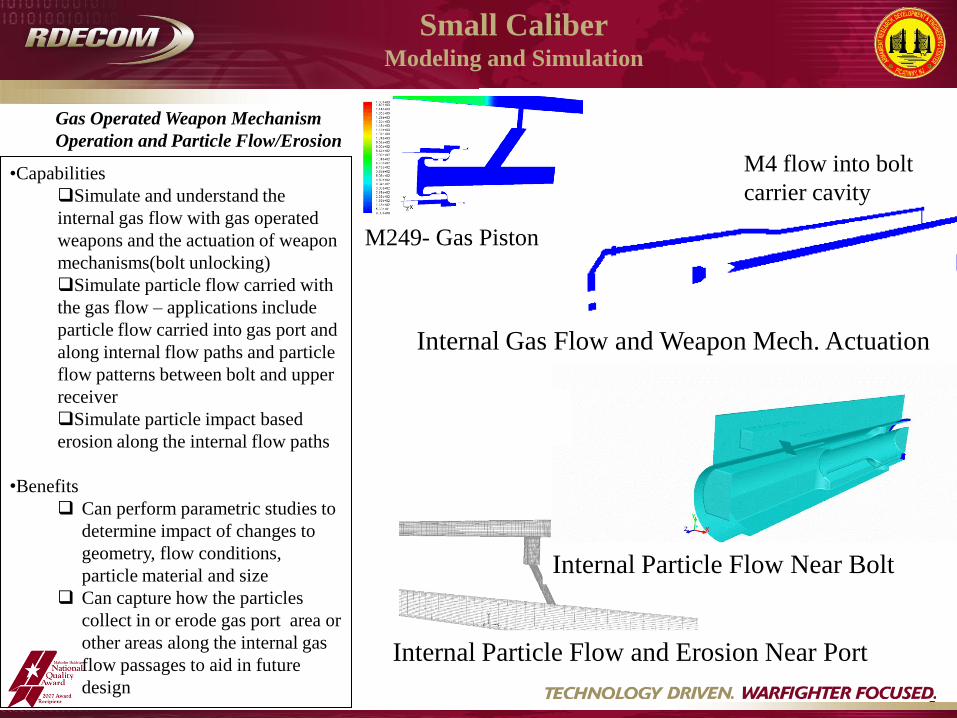
Internal Particle Flow and Erosion Near Port
Internal Gas Flow and Weapon Mech. Actuation
M4 flow into bolt
carrier cavity •Capabilities
Simulate and understand the
internal gas flow with gas operated
weapons and the actuation of weapon
mechanisms(bolt unlocking)
Simulate particle flow carried with
the gas flow – applications include
particle flow carried into gas port and
along internal flow paths and particle
flow patterns between bolt and upper
receiver
Simulate particle impact based
erosion along the internal flow paths
•Benefits
Can perform parametric studies to
determine impact of changes to
geometry, flow conditions,
particle material and size
Can capture how the particles
collect in or erode gas port area or
other areas along the internal gas
flow passages to aid in future
design
Gas Operated Weapon Mechanism
Operation and Particle Flow/Erosion
Internal Particle Flow Near Bolt
M249- Gas Piston

6
Particulate Flow
Small Caliber Modeling and Simulation
•Capabilities
Gun system phenomena operate where
particulate flows are NOT dilute so standard
built –in Lagrangian models may NOT be
applicable
Developed modeling method accounts for
particle presence in the flow and particle-
particle/particle-other object interactions
Various solid body interaction models
developed(spring/damper models, FEA)
•Benefits
Can show effects of particle size, particle
material/properties, gas flow conditions on
particle motion
Can explore methods to control or alter
particle motion
Can be applied to propellant burn
Can eventually be applied to erosion,
fouling, chemically reacting particles
Particle interaction with moving plate
Means to Control Particle Motion
Projectile spread Coupled CFD-FEA model
Particulate ejection with elastic/plastic interaction model

7
Chemistry model development, Temp H2 escapes
•Capabilities
High particle concentration conditions
typical of propellant burn can be simulated
with the application of the particle/flow
coupling and interaction modeling
methods
Burn rate based on local surface
conditions: first with single species of gas
generated, progressing to multiple species
and simplified chemistry
Local surface condition based model
assists in study of non-standard geometries
Customized real gas model and consistent
thermo/material properties, real gas chem.
equilibrium used in determining gas
species output at burn
•Benefits
Can better understand grain/gas/geometry
interaction
Can improve accuracy of simulations of
system operation, can enable study of
particle flow based events – erosion,
fouling particle reactions
Multiple gas species generated, chemistry, burn based on local
conditions- CO2 mass fraction
Burning of propellant grains- single gas species generated – Pressure
field Propellant Burn
Small Caliber Modeling and Simulation

8
Test Setup – Blast, Flash, Thermal Army Research Lab (ARL) Aerodynamics Experimental Facility (AEF)
PCB106B Gage – 1 m, 10 Deg
PCB337A1 Gage – 1 m, 90 Deg
PCB337A1 Gage – 1 m, 170 Deg
Four Omega OS523E-3
IR Thermometers
Suppressor and Barrel
Temperature
10 Deg
Rigid Weapon Mount
Small Caliber Experimental Testing

9
High-Speed Shadowgraph
Standard Flash Hider
Small Caliber Experimental Testing

10
High-Speed Flash Video
Suppressor A
Small Caliber Experimental Testing

11
Simulate shock
propagation (pressure vs.
time) at various flowfield
points.
Predict blast overpressure
peak levels to match with
experimental data.
M119 Howitzer
M120 Mortar
Predict impulse (integral
of force vs. time) on the
cannon system for legacy
and new designs.
Large Caliber Modeling and Simulation
Shock Propagation, Blast
Overpressure
and Impulse Prediction
105mm M119 Howitzer 120mm M120 Mortar
120mm M120 Mortar 105mm M119 Howitzer
12
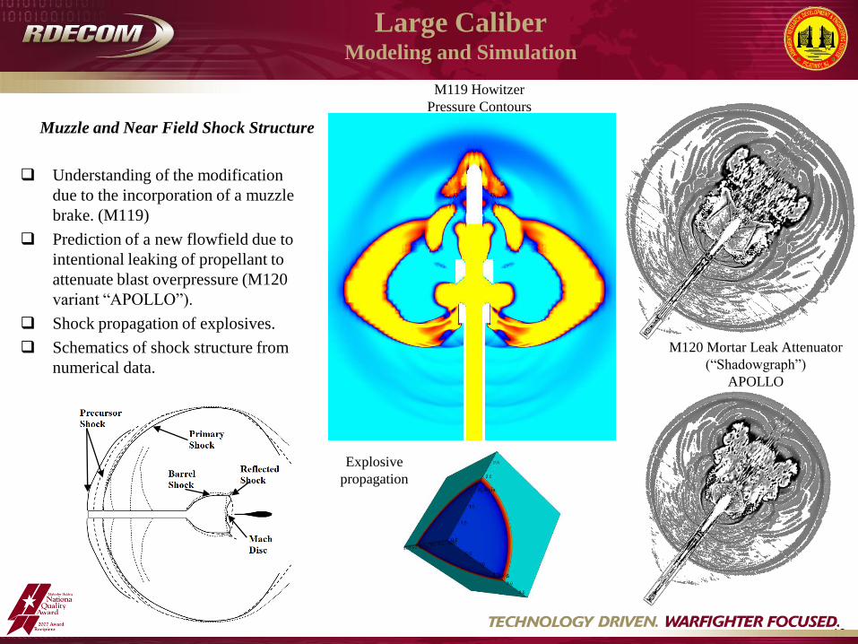
Understanding of the modification
due to the incorporation of a muzzle
brake. (M119)
Prediction of a new flowfield due to
intentional leaking of propellant to
attenuate blast overpressure (M120
variant “APOLLO”).
Shock propagation of explosives.
Schematics of shock structure from
numerical data.
Large Caliber Modeling and Simulation
Muzzle and Near Field Shock Structure
M120 Mortar Leak Attenuator
(“Shadowgraph”)
APOLLO
M119 Howitzer
Pressure Contours
Explosive
propagation
13
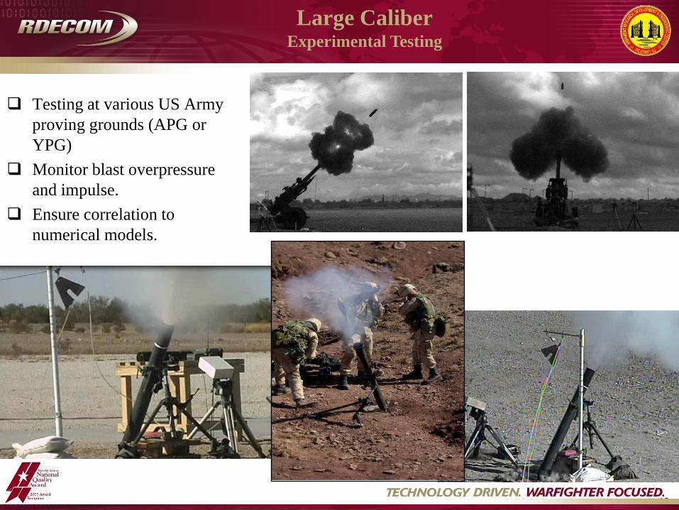
Large Caliber Experimental Testing
Testing at various US Army
proving grounds (APG or
YPG)
Monitor blast overpressure
and impulse.
Ensure correlation to
numerical models.

14
• Two primary numerical codes are utilized for fluids modeling at ARDEC.
• ANSYS Fluent
• ALE3D
• Small Caliber Numerical Analysis
• Gas operated weapon mechanism operation and particle flow/erosion
• Particulate flow
• Propellant burn and muzzle flow
• Large Caliber Numerical Analysis
• Shock propagation, blast overpressure and impulse prediction
• Muzzle and near field shock structure
• Small & Large Caliber Experimental Testing
• Multiple facilities and capabilities including blast, flash, and thermal
Conclusions
15
• Carson, R.A. and Sahni, O., “Plume-in-Plume Blast Attenuator,” Proceedings of the 27th International Symposium
on Ballistics, April 2013.
• Carson, R.A. and Sahni, O., “Numerical Investigation of Propellant Leak Methods in Large Caliber Cannons for
Blast Overpressure Attenuation,” Shock Waves, (Accepted April 2014).
• Carson, R.A. and Sahni, O., “Numerical Investigation of Channel Leak Geometry for Blast Overpressure
Attenuation in a Muzzle Loaded Large Caliber Cannon,” J. of Fluids Engineering, (Submitted March 2014).
• Carson, R.A. and Sahni, O., “Cannon Blast Scaling Utilizing a Propellant Channel Leak Method Blast Attenuator,”
(In Process).
• Carson, R.A. and Sahni, O., “Numerical Investigation of the Effect of Length of the Channel Leak Method on Blast Overpressure
Attenuation for Cannons,” Proceedings of the 28th International Symposium on Ballistics, September 2014.
• Cler, D.L., “Experimental Flow Diagnostics Investigations of the 25-mm, M4A1, Special Forces Combat Assault
Rifle Heavy, and Bare Muzzle Suppressed Flash and Blast Characteristics,” Technical Report ARWSE-TR-12003,
US Army ARDEC, Nov. 2013.
Recent or Upcoming Publications

16
Questions?