Advanced Power Electronic Interfaces for Distributed Energy - NREL
Upload
phungthienCategory
view
213download
0
NREL is a national laboratory of the U.S. Department of Energy, Office of Energy Efficiency & Renewable Energy, operated by the Alliance for Sustainable Energy, LLC.
Contract No. DE-AC36-08GO28308
2011 Alkaline Membrane Fuel Cell Workshop Final Report B. Pivovar National Renewable Energy Laboratory
Proceedings from the Alkaline Membrane Fuel Cell Workshop Arlington, Virginia May 8-9, 2011
Workshop Proceedings NREL/BK-5600-54297 February 2012

NREL is a national laboratory of the U.S. Department of Energy, Office of Energy Efficiency & Renewable Energy, operated by the Alliance for Sustainable Energy, LLC.
National Renewable Energy Laboratory 1617 Cole Boulevard Golden, Colorado 80401 303-275-3000 • www.nrel.gov
Contract No. DE-AC36-08GO28308
2011 Alkaline Membrane Fuel Cell Workshop Final Report B. Pivovar National Renewable Energy Laboratory
Proceedings from the Alkaline Membrane Fuel Cell Workshop Arlington, Virginia May 8-9, 2011
Prepared under Task No. HT12.5410
Workshop Proceedings NREL/BK-5600-54297 February 2012

NOTICE
This report was prepared as an account of work sponsored by an agency of the United States government. Neither the United States government nor any agency thereof, nor any of their employees, makes any warranty, express or implied, or assumes any legal liability or responsibility for the accuracy, completeness, or usefulness of any information, apparatus, product, or process disclosed, or represents that its use would not infringe privately owned rights. Reference herein to any specific commercial product, process, or service by trade name, trademark, manufacturer, or otherwise does not necessarily constitute or imply its endorsement, recommendation, or favoring by the United States government or any agency thereof. The views and opinions of authors expressed herein do not necessarily state or reflect those of the United States government or any agency thereof.
Available electronically at http://www.osti.gov/bridge
Available for a processing fee to U.S. Department of Energy and its contractors, in paper, from:
U.S. Department of Energy Office of Scientific and Technical Information P.O. Box 62 Oak Ridge, TN 37831-0062 phone: 865.576.8401 fax: 865.576.5728 email: mailto:[email protected]
Available for sale to the public, in paper, from:
U.S. Department of Commerce National Technical Information Service 5285 Port Royal Road Springfield, VA 22161 phone: 800.553.6847 fax: 703.605.6900 email: [email protected] online ordering: http://www.ntis.gov/help/ordermethods.aspx
Cover Photos: (left to right) PIX 16416, PIX 17423, PIX 16560, PIX 17613, PIX 17436, PIX 17721
Printed on paper containing at least 50% wastepaper, including 10% post consumer waste.
Alkaline Membrane Fuel Cell Workshop Final Report
Workshop held May 8-9, 2011 Crystal Gateway Marriott
1700 Jefferson Davis Highway Arlington, Virginia 22202
Organized by
The National Renewable Energy Laboratory
Sponsored by Department of Energy – Fuel Cell Technologies Program
Army Research Office
Lead Organizer Bryan Pivovar
Fuel Cell Group Leader National Renewable Energy Laboratory
1617 Cole Blvd Golden, Colorado 80401
Organizing Committee Dimitrios Papageorgopoulos, Department of Energy
Robert Mantz, Army Research Office Bryan Pivovar, National Renewable Energy Laboratory
Andrew Herring, Colorado School of Mines
Break-out Group Chairs James Boncella, Los Alamos National Laboratory
Andrew Herring, Colorado School of Mines Sanjeev Mukerjee, Northeastern University
Dario Dekel, CellEra, Inc. Anil Trehan, Commscope
Break-out Group Scribes Clay Macomber, National Renewable Energy Laboratory
Joe Elabd, Drexel University Jacob Spendelow, Los Alamos National Laboratory
Doug Wheeler, DJW Technologies Huyen Dinh, National Renewable Energy Laboratory

2
Table of Contents
Executive Summary ............................................................................................................ 3
Introduction ......................................................................................................................... 5
Workshop Objectives and Organization ............................................................................. 8
Workshop Agenda .............................................................................................................. 9
Workshop Main Session Presentations ............................................................................. 10
Breakout Sessions ............................................................................................................. 10
Breakout Session 1: Anion Exchange Membranes – Stability ..................................... 11
Breakout Session 2: Anion Exchange Membranes – Transport/Conductivity ............. 14
Breakout Session 3: Electrocatalysis in High pH Environments .................................. 15
Breakout Session 4: MEA Issues .................................................................................. 17
Breakout Session 5: System Issues ............................................................................... 19
AMFC Status and Target Discussion ................................................................................ 22
AMFC Membranes ....................................................................................................... 23
AMFC Electrocatalysis ................................................................................................. 23
AMFC Performance and Durability.............................................................................. 24
AMFC Systems ............................................................................................................. 24
References ......................................................................................................................... 24

3
Executive Summary A workshop addressing the current state-of-the-art in alkaline membrane fuel cells (AMFCs) was held May 8-9, 2011, at the Crystal Gateway Marriott in Arlington, Virginia. This workshop was the second of its kind, with the first being held December 11-13, 2006, in Phoenix, Arizona. The 2011 workshop and associated workshop report were created to assess the current state of AMFC technology (taking into account recent advances), investigate the performance potential of AMFC systems across all possible power ranges and applications, and identify the key research needs for commercial competitiveness in a variety of areas. The advances that AMFCs have made since the 2006 AMFC Workshop have been substantial. One of the most significant factors contributing to these advances has been the emergence of a commercial (or semi-commercial) anion exchange membrane (AEM) and ionomer solution specifically tailored for AMFCs (from Tokuyama Corporation). Prior to 2006, the power density and efficiency of AMFCs was exceptionally poor, with many demonstrated examples relying on the incorporation of aqueous base or carbonate in the anode feed stream. Typical power densities reported for AMFCs at this time were in the tens of mW/cm2 for electrolyte-free systems and up to ~100 mW/cm2 for systems that included free electrolyte. (Granted, most of these studies involved methanol as a fuel rather than hydrogen). Additionally, durability data on AMFCs were incredibly poor or non-existent and systems not containing free electrolyte were run on carbon dioxide (CO2)-free oxygen in most cases. AMFCs have now been demonstrated with much higher power densities (500 mW/cm2), significantly greater durability (thousands of hours), and some capacity to operate at higher temperatures (80°C) with limited tolerance to atmospheric CO2 (~400 ppm). These recent advances have helped demonstrate the promise that AMFCs hold. The performances to date may even be acceptable for some subset of applications, but for wider spread deployment of these systems, further challenges remain. The status of AMFC technology and remaining challenges were discussed in the context of five breakout sessions:
• Anion Exchange Membranes – Stability • Anion Exchange Membranes – Transport/Conductivity • Electrocatalysis in High pH Environments • MEA Issues • System Issues
A few common themes were discussed in multiple sessions. Namely, unlike proton exchange membrane fuel cells (PEMFCs), which have been studied in great detail with significant research investment, AMFCs suffer from a lack of (commercially available) standard materials; a lack of standard procedures (test conditions and protocols); and a lack of data (established baseline properties and performance). Additionally, the impact of carbonate, and a number of unresolved questions regarding carbonate, was discussed within each of the breakout sessions.

4
The body of the report focuses on the discussion that occurred within breakout sessions. In the Executive Summary, we present a few select highlights from each session.
Table 1. Select Highlights of Breakout Sessions Breakout Session Key Highlights Anion Exchange Membranes – Stability
Membrane stability with Tokuyama membranes has been demonstrated to a level at or near commercial impact. AEM stability remains inferior to proton exchange membranes under conditions relevant to fuel cell operation.
Anion Exchange Membranes – Transport/Conductivity
Conductivity of AEMs is significantly lower than acid membrane analogues. Relatively little transport property data exist for AEMs, but water transport is likely to be an even larger issue in AMFCs than PEMFCs.
Electrocatalysis in High pH Environments
Oxygen reduction under basic conditions using high-performance, durable, non-precious electrocatalysts has been reasonably demonstrated, leaving anode catalysis as the primary concern in stark contrast to acidic systems.
MEA Issues The most promising AMFC performance and durability reported to date has focused on H2 as a fuel, and is now commonly achieved without the addition of free electrolyte. Performance of single cells has increased significantly with ~500 mW/cm2 performance reported and durability in the thousands of hours.
System Issues System issues will depend on system-specific requirements, but work in this area is necessary to determine how much improvement is needed in each of the other areas to produce viable devices. CO2 from air or fuel has a major impact on system design and performance.
In spite of limited research effort, the advances made in the past few years in the area of AMFCs have been extremely impressive and are approaching commercial viability in at least limited application. The key advances have centered around the availability of advanced membranes and ionomers, and have allowed for significant increases in power density and lifetime. Significant challenges remain in several areas, with increased temperature operation and carbon dioxide tolerance high on the list. Based on the limited effort and high potential of AMFC systems (some of which has already been demonstrated), increased research funding is highly likely to further advance the technology and allow it to become increasingly commercially competitive and is strongly encouraged.
5
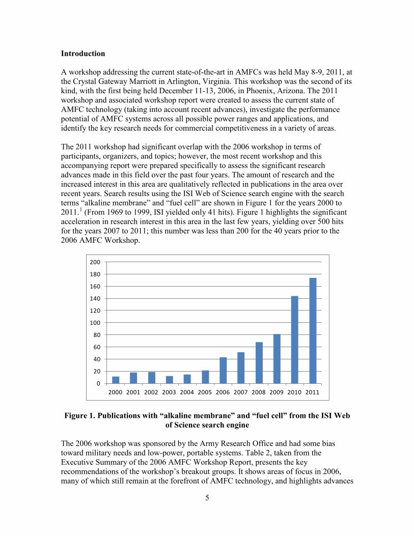
Introduction A workshop addressing the current state-of-the-art in AMFCs was held May 8-9, 2011, at the Crystal Gateway Marriott in Arlington, Virginia. This workshop was the second of its kind, with the first being held December 11-13, 2006, in Phoenix, Arizona. The 2011 workshop and associated workshop report were created to assess the current state of AMFC technology (taking into account recent advances), investigate the performance potential of AMFC systems across all possible power ranges and applications, and identify the key research needs for commercial competitiveness in a variety of areas. The 2011 workshop had significant overlap with the 2006 workshop in terms of participants, organizers, and topics; however, the most recent workshop and this accompanying report were prepared specifically to assess the significant research advances made in this field over the past four years. The amount of research and the increased interest in this area are qualitatively reflected in publications in the area over recent years. Search results using the ISI Web of Science search engine with the search terms “alkaline membrane” and “fuel cell” are shown in Figure 1 for the years 2000 to 2011.1 (From 1969 to 1999, ISI yielded only 41 hits). Figure 1 highlights the significant acceleration in research interest in this area in the last few years, yielding over 500 hits for the years 2007 to 2011; this number was less than 200 for the 40 years prior to the 2006 AMFC Workshop.
Figure 1. Publications with “alkaline membrane” and “fuel cell” from the ISI Web
of Science search engine The 2006 workshop was sponsored by the Army Research Office and had some bias toward military needs and low-power, portable systems. Table 2, taken from the Executive Summary of the 2006 AMFC Workshop Report, presents the key recommendations of the workshop’s breakout groups. It shows areas of focus in 2006, many of which still remain at the forefront of AMFC technology, and highlights advances
0
20
40
60
80
100
120
140
160
180
200
2000 2001 2002 2003 2004 2005 2006 2007 2008 2009 2010 2011

6
made since this workshop. The 2006 AMFC Workshop Report2 also serves as a reference to this report, which presents far more data and rationale for pursuing AMFCs. Additionally, two review articles on membranes for AMFCs3,4—published after the 2011 workshop was held—further serve as resources that go far beyond the depth presented in this report and give evidence of the rising interest in this field. Table 2. Key Breakout Group Recommendations from the 2006 AMFC Workshop
Report Breakout Group Key Recommendations Anion Exchange Membrane/Cation Stability and Conductivity
Improve cation stability • Current generation materials have had
significant limitations due to chemical stability of the cations
• Explore different classes and novel cations • Explore degradation mechanisms and
dependence on temperature and water content Improve conductivity
• Conductivity in these systems is significantly lower than in acid membrane systems
• The role of cation basicity, water content and membrane morphology need to be related to conductivity
• Carbonate formation needs further investigation Electrocatalysis in High pH Environments
Catalysts for complex fuel oxidation • The ability of alkaline systems to effectively
utilize complex fuels like ethanol is a significant advantage over related systems
• How they do this and whether or not they can be effectively expanded to include more complex fuels (like gasoline) is an area that needs further investigation
Utilizing Anion Exchange Membranes in Fuel Cells
Membrane electrode assembly (MEA) fabrication • Current generation cells only obtain system-
useful performance with the addition of free electrolyte
• Research to improve performance of cells without free electrolyte are required for many applications
System Considerations/Needs System issues will depend on system-specific requirements, but work in this area is necessary to determine how much improvement is needed in each of the other areas to produce viable devices.
The motivating factors for pursuing AMFCs are reasonably well established and generally agreed upon in the scientific community today. AMFCs compete with other

7
technologies such as PEMFCs, batteries, alkaline fuel cells (AFCs) and internal combustion devices. In contrast to internal combustion devices, electrochemical devices avoid the Carnot cycle and therefore offer significantly higher efficiencies. In comparison with PEMFCs, AMFCs offer the advantage of avoiding Pt or Pt group metal (PGM) electrocatalysts, one of the primary limitations in the commercial deployment of fuel cells. Fuel cells, in general, have distinct advantages over batteries because they use high-energy density fuels. AMFCs offer significant advantages over traditional (aqueous KOH-based) alkaline fuel cells, in that membrane-based systems prevent carbonate precipitation, avoid issues of electrolyte migration, mitigate corrosion concerns, can be operated with differential pressures, and offer design simplification. The primary advantage of AMFCs compared to traditional PEMFCs is their ability to perform efficiently and durably with non-PGM catalysts. Other advantages include increased materials stability at high pH (allowing for cheaper system materials including, but not limited to catalysts), increased electrocatalytic activity in alkaline conditions (particularly for organic fuels such as methanol or ethanol), increased fuel choices in basic environments (ammonia, borohydride), and decreased fuel crossover rates and potentially improved water management (arising from electro-osmotic drag and the flux of hydroxide ions in the opposite direction of protons in traditional PEMFCs). Conversely, there are several factors that either limit or have been perceived to limit AMFCs. These factors were the primary focus of the workshop, were discussed in the breakout sessions, and are presented in detail later in this report. The advances that AMFCs have made since the 2006 AMFC Workshop have been substantial. One of the most significant factors contributing to these advances has been the emergence of a commercial (or semi-commercial) AEM and ionomer solution specifically tailored for AMFCs (from Tokuyama Corporation). Prior to 2006, the power density and efficiency of AMFCs was exceptionally poor, with many demonstrated examples relying on the incorporation of aqueous base or carbonate in the anode feed stream. Typical power densities reported for AMFCs at this time were in the tens of mW/cm2 for electrolyte-free systems and up to ~100 mW/cm2 for systems that included free electrolyte. (Granted, most of these studies involved methanol as a fuel, rather than hydrogen).2 Additionally, durability data on AMFCs were incredibly poor or non-existent and systems not containing free electrolyte were run on CO2-free oxygen in most cases. AMFCs have now been demonstrated with much higher power densities, significantly greater durability, and some capacity to operate at higher temperatures (nearing 80°C) with limited tolerance to atmospheric CO2. These recent advances have helped demonstrate the promise that AMFCs hold. The performances to date may even be acceptable for some subset of applications, but for wider spread deployment of these systems, further challenges remain. These challenges were a major focus of the workshop and will be highlighted in the discussion of the breakout sessions and in the “AMFC Status and Target Discussion” section of this report.

8
Workshop Objectives and Organization The objectives of this workshop were to: 1) assess the state of AMFC technology; 2) identify the limitations of AMFC technology; 3) establish the performance potential of AMFC systems; and 4) establish and prioritize research needs for these systems. The workshop was held May 8-9, 2011, at the Crystal Gateway Marriott in Arlington, Virginia. A group of nearly 100 participants attended, including national and international experts in the areas of fuel cells, polymer electrolytes, electrocatalysts, and power systems. These participants represented industry, academia, national laboratories and the military. The workshop agenda (included below) opened with a series of invited talks on membranes, catalysis and recent advances in AMFCs. Breakout groups met Sunday afternoon (May 8) and Monday morning (May 9) to discuss specific topical areas. Each one of these sessions had a facilitator to stimulate discussion and a scribe to capture the discussion. Following the breakout sessions, a joint session was reconvened in which the facilitator of each breakout session presented the session’s findings.

9
Workshop Agenda SUNDAY, MAY 8, 2011 11:00 a.m. - 1:00 p.m. Registration 1:00 p.m. - 1:15 p.m. Welcome and Opening Remarks 1:15 p.m. - 1:45 p.m. Workshop Overview: Bryan Pivovar, NREL 1:45 p.m. - 2:15 p.m. Alkaline Membrane Research Overview:
Professor Andy Herring, Colorado School of Mines 2:15 p.m. - 2:45 p.m. Alkaline Electrocatalysis Research Overview:
Professor Sanjeev Mukerjee, Northeastern University 2:45 p.m. - 3:15 p.m. AMFCs: Tokuyama Perspective:
Kenji Fukuta, Tokuyama Corporation 3:15 p.m. - 3:45 p.m. Break 3:45 p.m. - 4:15 p.m. AMFCs: CellEra perspective:
Shimshon Gottesfeld, CellEra, Inc. 4:15 p.m. - 4:30 p.m. Move to Breakout Sessions 4:30 p.m. - 6:00 p.m. Breakout Sessions
Session 1: Anion Exchange Membranes – Stability Session 2: Anion Exchange Membranes –
Transport/Conductivity Session 3: Electrocatalysis in High pH Environments (non-
precious, complex fuels) Session 4: MEA Issues (ionomer solutions, electrode
performance/durability) Session 5: System Issues (carbonate, specific materials, water
management)
MONDAY, MAY 9, 2011 8:00 a.m. - 9:45 a.m. Breakout Sessions
Session 1: Anion Exchange Membranes – Stability Session 2: Anion Exchange Membranes –
Transport/Conductivity Session 3: Electrocatalysis in High pH Environments (non-
precious, complex fuels) Session 4: MEA Issues (ionomer solutions, electrode
performance/durability) Session 5: System Issues (carbonate, specific materials, water
management) 9:45 a.m. - 10:15 a.m. Break 10:15 a.m. - 12:00 p.m. Joint Session Outbrief from Breakout Sessions

10
Workshop Main Session Presentations The main session presentations can be found online,5 and provided much of the basis for later discussions during breakout sessions. Presentations were chosen to have synergy with the breakout sessions and a focus was placed on cutting-edge, often unpublished, results. Professors Andy Herring (Colorado School of Mines) and Sanjeev Mukerjee (Northeastern University) focused on alkaline membranes and electrocatalysis, respectively. Two AMFC industrial perspectives from Tokuyama Corporation (Dr. Kenji Fukuta) and CellEra, Inc. (Dr. Shimshon Gottesfeld) were also presented. Tokuyama has played a major role in advancing AMFC technology through its development of alkaline membranes and ionomer solutions specifically for AMFCs, and CellEra, Inc. has focused on the commercial development and deployment of AMFC systems. Many key points from these presentations will be presented within the breakout session summaries; however, it is worth noting that the fuel cell performance and durability presented (particularly in the industrial perspective talks) clearly demonstrated significant advances in AMFCs. These devices are approaching the performance range of PEMFCs. Breakout Sessions Five different breakout sessions were held:
1) Anion Exchange Membranes – Stability and Conductivity 2) Anion Exchange Membranes – Transport/Conductivity 3) Electrocatalysis in High pH Environments 4) MEA Issues 5) System Issues
These sessions paralleled the four breakout sessions of the 2006 workshop, with the AEM topic split into two sessions, one specifically covering stability and the other covering transport and conductivity. This reflects the current focus on this area and the number of workshop participants with interest in this area. Prior to the workshop, as part of the registration process, breakout session attendance was probed, targeting 15-20 attendees per session. Each of the sessions had approximately this level of participation, with System Issues having slightly less representation than the other sessions. (This reflects the specific interests of the attendees, not the challenges or needs within the topic of system issues). A number of common themes resulted from the breakout sessions, including the lack of standard processes (test conditions and protocols), the lack of standard materials, and the lack of data for AMFC materials and systems. Additionally, the role of hydroxide/ carbonate/bicarbonate equilibrium on AMFC systems and the implications of carbonate on the use of carbonaceous fuels or ambient (CO2-containing) air were discussed in several sessions. The following sections provide summaries of each of the breakout sessions. The outbrief presentations from each of these breakout sessions are available online.5

11
Breakout Session 1: Anion Exchange Membranes – Stability The chemical stability of AEMs remains a primary issue, and is continually being pursued by the research community.3,4 The stability of AEMs was the focus topic of a breakout session independent of conductivity and transport (breakout session 2). The stability of AEMs has become better quantified recently, and the performance of membranes in fuel cells has shown durability reaching into the hundreds if not thousands of hours at temperatures as high as 60°-80°C.6,7,8 This stability is far less than current PEM perfluorosulfonic acid (PFSA) analogues,9 but it may be sufficient for some applications and approaches required durability levels for others. Other stability issues such as mechanical properties, durability to relative humidity (RH) cycling, and chemical attack beyond hydroxide (oxidative or radical attack) have been studied to a much lesser degree (and in many cases perhaps not at all), primarily due to the demonstrated susceptibility of AEMs toward hydroxide attack. In the area of chemical stability, specific conditions such as temperature, relative humidity (or degree of hydration), and counterion form (for example, OH- versus CO3
2- versus HCO3
-), have a significant impact on the chemical stability of various AEM materials.10 Most work to date has focused on high temperature (often 80°C), liquid equilibrated, OH--form AEMs, as these test conditions have relevance and usually show degradation over reasonable timeframes (as opposed to lower temperature or alternate counterion tests which show high durability) and are more simply applied than vapor-equilibrated tests (which would be expected to also accelerate degradation).8,11 The chemical decomposition of AEMs can occur in three locations: the cation, the backbone or the tether (the chemical linkage between the backbone and cation that usually exists, although in some cases, the cation can be incorporated within the backbone12). The backbones investigated to date have often been hydrocarbon, although fluoropolymers (Tosflex)13 have also been demonstrated. While backbones need to demonstrate stability, there are numerous options, many of which have demonstrated stability under target operating conditions (wet, high temperature, high pH), and therefore, have received less focus. The stability of cations and tethers, on the other hand, represent an area of immediate need and an area of current research focus. The chemical reactions that lead to degradation of cations due to hydroxide attack have been primarily attributed to nucleophilic (SN2) attack and Hoffman (Beta) elimination; however, an ylide mechanism and rearrangement products have also been reported.10 The most common degradation reactions, highlighted in Figure 2, are highly dependent on the structure of the cation, the temperature, and the presence of water. The specifics regarding the mechanisms and rates of reactions are areas that have significant gaps and require further study.
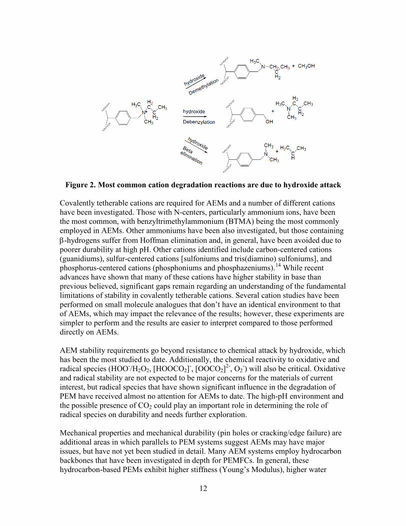
12
Figure 2. Most common cation degradation reactions are due to hydroxide attack
Covalently tetherable cations are required for AEMs and a number of different cations have been investigated. Those with N-centers, particularly ammonium ions, have been the most common, with benzyltrimethylammonium (BTMA) being the most commonly employed in AEMs. Other ammoniums have been also investigated, but those containing β-hydrogens suffer from Hoffman elimination and, in general, have been avoided due to poorer durability at high pH. Other cations identified include carbon-centered cations (guanidiums), sulfur-centered cations [sulfoniums and tris(diamino) sulfoniums], and phosphorus-centered cations (phosphoniums and phosphazeniums).14 While recent advances have shown that many of these cations have higher stability in base than previous believed, significant gaps remain regarding an understanding of the fundamental limitations of stability in covalently tetherable cations. Several cation studies have been performed on small molecule analogues that don’t have an identical environment to that of AEMs, which may impact the relevance of the results; however, these experiments are simpler to perform and the results are easier to interpret compared to those performed directly on AEMs. AEM stability requirements go beyond resistance to chemical attack by hydroxide, which has been the most studied to date. Additionally, the chemical reactivity to oxidative and radical species (HOO-/H2O2, [HOOCO2]-, [OOCO2]2-, O2
-) will also be critical. Oxidative and radical stability are not expected to be major concerns for the materials of current interest, but radical species that have shown significant influence in the degradation of PEM have received almost no attention for AEMs to date. The high-pH environment and the possible presence of CO2 could play an important role in determining the role of radical species on durability and needs further exploration. Mechanical properties and mechanical durability (pin holes or cracking/edge failure) are additional areas in which parallels to PEM systems suggest AEMs may have major issues, but have not yet been studied in detail. Many AEM systems employ hydrocarbon backbones that have been investigated in depth for PEMFCs. In general, these hydrocarbon-based PEMs exhibit higher stiffness (Young’s Modulus), higher water

13
uptake (larger dimensional change), and poorer durability to accelerated test protocols based on RH cycling. AEMs, due to their lower conductivity, typically require higher ion exchange capacities (IECs), making these systems more prone to water uptake and thus vulnerable to failure mechanisms arising from dimensional changes. There is a need for further testing of mechanical durability in these systems because they have shown chemical stability that approaches relevance for specific applications. The needed stability also depends on how the device is being employed, since some applications operating under fixed conditions without frequent start-up and shut down have requirements that are quite different from a dynamic system that experiences intermittent operation.
Figure 3. AEM durability data from Tokuyama membranes under basic conditions
In considering factors such as status and targets for membrane stability, it is worth presenting data from Tokuyama that involve its A201 membrane. This membrane has been studied at some length and represents the membrane for which much of the best AMFC performance and durability data have been obtained.7,8 Figure 3 presents results from Tokuyama for its A201 membrane and an experimental membrane at 80°C in a 12 wt% ethanol and 20 wt% KOH solution (for A201, ~70°C as shown in Figure 3 is an estimate for temperature stability based on 80°C testing).7 The durability of A201, as gauged by IEC over time, shows reasonable durability with slightly less than 20% of the IEC lost after 1,000 hours. The new developmental membrane using a different ion-exchange group shows much better stability in this test, losing only a few percent IEC after 1,000 hours at 80°C. The stability of A201 suggests that at temperatures below 70°C, membrane stability may be sufficient for some applications. The developmental membrane offers the possibility of greatly increased stability, although a number of factors still need to be considered (for example, the appropriateness of this test for stability, whether or not the new membrane satisfies other performance requirements that A201 has already demonstrated in fuel cell testing, and the appropriateness of this membrane for commercial applications). Targets/Status
• Current: 1,000 h with 10% loss in performance

14
• New Tokuyama membrane: 2,000 h with 1%-3% loss in performance • Goal: >5,000 h with 1%-3% loss in performance
Breakout Session 2: Anion Exchange Membranes – Transport/Conductivity The transport and conductivity of AEMs were handled in a breakout session independent of stability. Conductivity of AEMs is lower than their PEM counterparts, as might be expected due to the increased conduction of protons in water compared to hydroxide in water.15,16 This means that ohmic losses are a larger potential concern for AEMs than PEMs. Additionally, water management—and the water uptake and transport characteristics—of AEMs are also a larger concern for AEMs due to the lower conductivity and stability of these materials compared to PEMs and changes related to the direction of ion flow and the production and consumption of water in AMFCs. In the areas of transport and conductivity, AEMs can leverage the vast amount of effort already performed on PEMs. Conductivity is typically the first property characterized for any ion-conducting polymer. Lessons learned investigating PEMs with different backbone chemistries, different degrees of phase separation, the dependence of properties with RH, impact of ion exchange capacity, and the impacts of crosslinking mean that researchers investigating AEMs do not have to start from a blank slate. The extensive work on PEMs also means that most of the equipment and techniques used to characterize target properties for AEMs are well established. Transport properties primarily focus on water transport properties, which include water diffusion coefficients (such as the self-diffusion coefficient and the permeation coefficient) and electro-osmotic drag; however, reactant crossover rates and water uptake (including dimensional changes) were also discussed. Within the area of transport and conductivity, a number of research gaps exist—the hydration number (number of water molecules per base site), water uptake and dimensional changes, the water self-diffusion coefficient (using pulsed field gradient NMR), the water permeation coefficient (using a permeation cell), and conductivity of AEMs—all as a function of RH, counterion form, and variations in polymer chemistry (including crosslinking and additives). A major difference does exist between AEMs and PEMs; AEMs suffer from hydroxide/carbonate/bicarbonate equilibrium, and the properties of AEMs (particularly conductivity) can be highly influenced by the anion. The oxygen reduction reaction in AMFCs produces hydroxide. CO2 from air or as a byproduct of carbonaceous fuel oxidation will lead to the formation of carbonates. As carbonate equilibrium is favored in high pH systems, a major issue for these systems is either operating as mixed conductors or operating in the absence of CO2. These issues were also discussed in other breakout sessions, as they are critical and require further investigation in order to properly assess the potential impact of AMFC technology.

15
There was significant discussion about the difficulty of measuring AEM properties in the hydroxide form. Even at relatively low atmospheric concentrations (~400 ppm), CO2 quickly equilibrates with membranes forming carbonates, and it is difficult to precisely control or know at any given time the ratio of different anions within an AEM.8 There were suggestions that even using glove boxes or ultra-pure inert atmospheres may be insufficient to prevent carbonate from getting into AEMs, although other reports suggest a 4x change in conductivity between carbonate and hydroxide form could be reproducibly obtained when performed in well-controlled environments. Because properties (particularly stability and conductivity) are highly influenced by carbonate equilibrium, standardized protocols become even more critical. The easiest technique (which is frequently employed) would be testing AEMs in solutions containing known counterion concentrations (typically excess base). This ensures that the counterion is known, but means that measurements must be carried out in liquid-equilibrated samples (even though vapor-equilibrate properties are also desired) and makes conductivity measurements more complicated because of the conductivity associated with the free aqueous base. Beyond transport measurements, this session also included discussions of structure-property relationships and the use of other tools and characterization techniques to better understand and modify transport properties. Specific examples of areas of needs included computational modeling; spectroscopic studies (NMR, ESR, FTIR, Raman); scattering studies (SANS, SAXS, XRD); and microscopy. These tools have been applied extensively in the study of PEMs. The following bullets were discussed as high priority needs in the outbrief presentation: • A standard and available AEM (similar to Nafion in PEMs) • Defined standard experimental conditions and protocols • Fundamental studies in transport mechanisms and mechanical properties • Development of more new AEMs with alternative chemistries (new cation and
backbone chemistries)
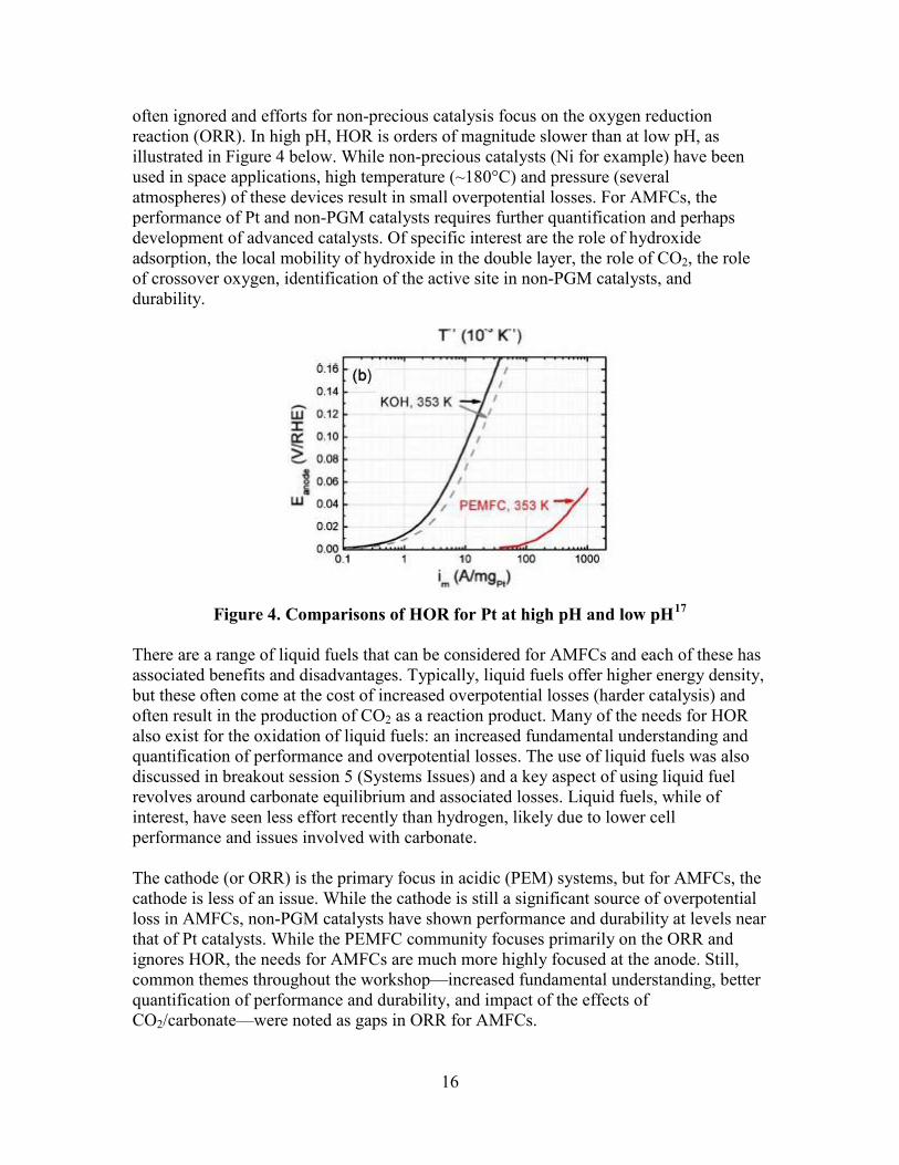
Breakout Session 3: Electrocatalysis in High pH Environments One of the most important factors in pursuing AEMs (as opposed to PEMs) for fuel cell applications is the ability to avoid precious metal catalysis, aided by the enhanced materials stability of high pH environments compared to low pH environments. This breakout session focused on four areas: hydrogen at the anode, liquid fuels at the anode, oxygen at the cathode, and the catalyst-electrolyte interface. Common themes of increased fundamental understanding (in particular, focusing on differences between high and low pH) and improved quantification of performance (benchmarking) resonated for both anode and cathode electrocatalysis. Hydrogen as a fuel has been of interest due to its relative ease of electrocatalytic conversion. In AMFCs, hydrogen has a number of remaining questions in which increased fundamental understanding of the hydrogen oxidation reaction (HOR) on either Pt or candidate non-PGM catalysts would be of value. In particular, HOR is usually considered to be facile compared to other fuel cell reactions. In PEMs, anode loading is
16
often ignored and efforts for non-precious catalysis focus on the oxygen reduction reaction (ORR). In high pH, HOR is orders of magnitude slower than at low pH, as illustrated in Figure 4 below. While non-precious catalysts (Ni for example) have been used in space applications, high temperature (~180°C) and pressure (several atmospheres) of these devices result in small overpotential losses. For AMFCs, the performance of Pt and non-PGM catalysts requires further quantification and perhaps development of advanced catalysts. Of specific interest are the role of hydroxide adsorption, the local mobility of hydroxide in the double layer, the role of CO2, the role of crossover oxygen, identification of the active site in non-PGM catalysts, and durability.
Figure 4. Comparisons of HOR for Pt at high pH and low pH17
There are a range of liquid fuels that can be considered for AMFCs and each of these has associated benefits and disadvantages. Typically, liquid fuels offer higher energy density, but these often come at the cost of increased overpotential losses (harder catalysis) and often result in the production of CO2 as a reaction product. Many of the needs for HOR also exist for the oxidation of liquid fuels: an increased fundamental understanding and quantification of performance and overpotential losses. The use of liquid fuels was also discussed in breakout session 5 (Systems Issues) and a key aspect of using liquid fuel revolves around carbonate equilibrium and associated losses. Liquid fuels, while of interest, have seen less effort recently than hydrogen, likely due to lower cell performance and issues involved with carbonate. The cathode (or ORR) is the primary focus in acidic (PEM) systems, but for AMFCs, the cathode is less of an issue. While the cathode is still a significant source of overpotential loss in AMFCs, non-PGM catalysts have shown performance and durability at levels near that of Pt catalysts. While the PEMFC community focuses primarily on the ORR and ignores HOR, the needs for AMFCs are much more highly focused at the anode. Still, common themes throughout the workshop—increased fundamental understanding, better quantification of performance and durability, and impact of the effects of CO2/carbonate—were noted as gaps in ORR for AMFCs.
17
The catalyst-electrolyte interface (or the environment for catalysis) is also a concern. To date, a significant amount of work has been performed in aqueous base (KOH or NaOH), but very little has been performed using ionomer electrolytes or bases that more closely resemble the covalently tetherable cationic moieties in AEMs (tetralkyl ammoniums and others). The impact of the environment on catalysis (including pH, which depends on carbonate equilibrium) also remains a gap in the research community.
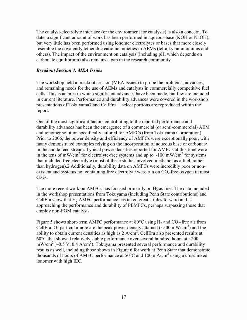
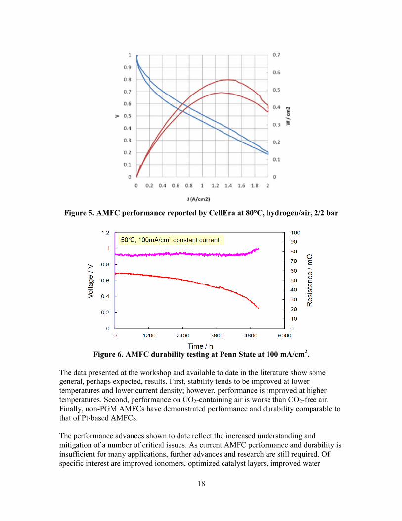
Breakout Session 4: MEA Issues The workshop held a breakout session (MEA Issues) to probe the problems, advances, and remaining needs for the use of AEMs and catalysts in commercially competitive fuel cells. This is an area in which significant advances have been made, but few are included in current literature. Performance and durability advances were covered in the workshop presentations of Tokuyama7 and CellEra18; select portions are reproduced within the report. One of the most significant factors contributing to the reported performance and durability advances has been the emergence of a commercial (or semi-commercial) AEM and ionomer solution specifically tailored for AMFCs (from Tokuyama Corporation). Prior to 2006, the power density and efficiency of AMFCs were exceptionally poor, with many demonstrated examples relying on the incorporation of aqueous base or carbonate in the anode feed stream. Typical power densities reported for AMFCs at this time were in the tens of mW/cm2 for electrolyte-free systems and up to ~100 mW/cm2 for systems that included free electrolyte (most of these studies involved methanol as a fuel, rather than hydrogen).2 Additionally, durability data on AMFCs were incredibly poor or non-existent and systems not containing free electrolyte were run on CO2-free oxygen in most cases. The more recent work on AMFCs has focused primarily on H2 as fuel. The data included in the workshop presentations from Tokuyama (including Penn State contributions) and CellEra show that H2 AMFC performance has taken great strides forward and is approaching the performance and durability of PEMFCs, perhaps surpassing those that employ non-PGM catalysts. Figure 5 shows short-term AMFC performance at 80°C using H2 and CO2-free air from CellEra. Of particular note are the peak power density attained (~500 mW/cm2) and the ability to obtain current densities as high as 2 A/cm2. CellEra also presented results at 60°C that showed relatively stable performance over several hundred hours at ~200 mW/cm2 (~0.5 V, 0.4 A/cm2). Tokuyama presented several performance and durability results as well, including those shown in Figure 6 for work at Penn State that demonstrate thousands of hours of AMFC performance at 50°C and 100 mA/cm2 using a crosslinked ionomer with high IEC.
18
Figure 5. AMFC performance reported by CellEra at 80°C, hydrogen/air, 2/2 bar
Figure 6. AMFC durability testing at Penn State at 100 mA/cm2.
The data presented at the workshop and available to date in the literature show some general, perhaps expected, results. First, stability tends to be improved at lower temperatures and lower current density; however, performance is improved at higher temperatures. Second, performance on CO2-containing air is worse than CO2-free air. Finally, non-PGM AMFCs have demonstrated performance and durability comparable to that of Pt-based AMFCs. The performance advances shown to date reflect the increased understanding and mitigation of a number of critical issues. As current AMFC performance and durability is insufficient for many applications, further advances and research are still required. Of specific interest are improved ionomers, optimized catalyst layers, improved water
19
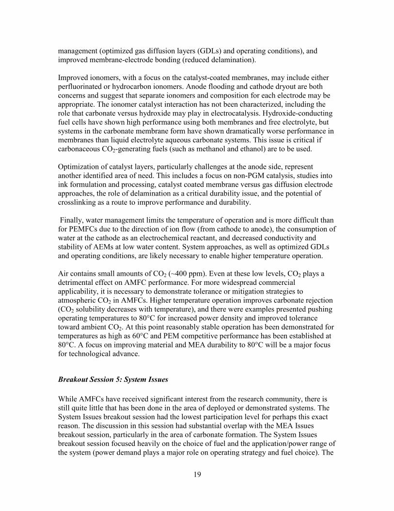
management (optimized gas diffusion layers (GDLs) and operating conditions), and improved membrane-electrode bonding (reduced delamination). Improved ionomers, with a focus on the catalyst-coated membranes, may include either perfluorinated or hydrocarbon ionomers. Anode flooding and cathode dryout are both concerns and suggest that separate ionomers and composition for each electrode may be appropriate. The ionomer catalyst interaction has not been characterized, including the role that carbonate versus hydroxide may play in electrocatalysis. Hydroxide-conducting fuel cells have shown high performance using both membranes and free electrolyte, but systems in the carbonate membrane form have shown dramatically worse performance in membranes than liquid electrolyte aqueous carbonate systems. This issue is critical if carbonaceous CO2-generating fuels (such as methanol and ethanol) are to be used. Optimization of catalyst layers, particularly challenges at the anode side, represent another identified area of need. This includes a focus on non-PGM catalysis, studies into ink formulation and processing, catalyst coated membrane versus gas diffusion electrode approaches, the role of delamination as a critical durability issue, and the potential of crosslinking as a route to improve performance and durability. Finally, water management limits the temperature of operation and is more difficult than for PEMFCs due to the direction of ion flow (from cathode to anode), the consumption of water at the cathode as an electrochemical reactant, and decreased conductivity and stability of AEMs at low water content. System approaches, as well as optimized GDLs and operating conditions, are likely necessary to enable higher temperature operation. Air contains small amounts of CO2 (~400 ppm). Even at these low levels, CO2 plays a detrimental effect on AMFC performance. For more widespread commercial applicability, it is necessary to demonstrate tolerance or mitigation strategies to atmospheric CO2 in AMFCs. Higher temperature operation improves carbonate rejection (CO2 solubility decreases with temperature), and there were examples presented pushing operating temperatures to 80°C for increased power density and improved tolerance toward ambient CO2. At this point reasonably stable operation has been demonstrated for temperatures as high as 60°C and PEM competitive performance has been established at 80°C. A focus on improving material and MEA durability to 80°C will be a major focus for technological advance.
Breakout Session 5: System Issues While AMFCs have received significant interest from the research community, there is still quite little that has been done in the area of deployed or demonstrated systems. The System Issues breakout session had the lowest participation level for perhaps this exact reason. The discussion in this session had substantial overlap with the MEA Issues breakout session, particularly in the area of carbonate formation. The System Issues breakout session focused heavily on the choice of fuel and the application/power range of the system (power demand plays a major role on operating strategy and fuel choice). The

20
presented findings from this breakout group are shown in Tables 3 and 4 for alcohol- and hydrogen-fueled AMFC applications, respectively. Like other breakout sessions, there was discussion involving the need for standard materials and methods for research and development testing. This breakout session also included a discussion on the needs for pre-competitive benchmarking of system performance and techno-economic analysis.
Table 3. Alcohol Fuel Applications and Power Ranges
Application Description Power Range Military Remote sensor <10 W Soldier power 20-50 W Battery charger 300 W Commercial Consumer electronics <100 W Recreation <500 W
Table 4. Hydrogen Fuel Applications and Power Ranges
Description Power Range Back-up 1-10 kW Material Handling 1-10 kW Transportation 20-100 kW Residential/Combined Heat and Power 1-10 kW Reversible Fuel Cells TBD Auxiliary Power Units 1-20 kW
Alcohol and hydrogen were chosen as the two focus fuels, although there was debate on fuel applications and power ranges in other categories (such as gaseous versus liquid or CO2-generating versus CO2–free). Other potential fuels for consideration discussed included hydrazine, borohydride, ethylene glycol, formic acid, and dimethyl ether. Each different fuel has specific concerns, and alcohols and hydrogen were chosen as the focus because they were generally perceived to have the most promise. Within the alcohol sub-group, methanol and ethanol were primarily considered, and much of the discussion between hydrogen and alcohol as fuels focused on key issues involving carbonate formation and catalysis, themes repeated throughout this report. Carbonate issues were recognized as being of critical importance for most AMFC approaches, as even ambient CO2 levels have resulted in significant performance loss. The carbonate issue is dramatically different when considering a CO2-generating fuel compared to hydrogen-fueled AMFCs. In the case of a CO2-generating fuel (alcohol, for example), the ability to operate efficiently in the presence of CO2 needs to be properly assessed. For hydrogen, there is a major push to make AMFCs more tolerant to ambient CO2 levels and self-purging of carbonate. Engineering approaches for dealing with CO2 is possible (for example, scrubbing CO2 from ambient air or the addition of alkaline or carbonate solutions to fuel feed streams). In general, these approaches have been demonstrated as technologically feasible, but the
21
added cost and weight as well as the decreased system efficiency associated with them in most cases makes them impractical and in the best cases undesirable. Scrubbing of CO2 from air was presented as a viable initial approach for AMFCs; however, the economic and system impact of such an approach has not yet been fully demonstrated. Additionally, the use of reforming systems to produce hydrogen was also presented, bringing up additional CO2-related issues. Long-term focus for AMFC systems envision ambient operation without free electrolyte with the use of terrestrial (CO2-containing) air. Specific comments were presented for short-, medium- and long-term timeframes for hydrogen and alcohol as a fuel, summarized in Table 5.
Table 5. Breakout Session Comments as a Function of Fuel and Timeframe for AMFCs
Timeframe Hydrogen Fuel Alcohol Fuel Near term (3-5 years) Back-up power
• Up to 5 kW • Durability ≥ 2,000 h • Reliability = 1,000
start/stop cycles • Ordinary air operation at
ambient temperature (CO2 scrubber part of system)
N/A
Medium term (5-7 years)
Back-up power and material handling
• Up to 10 kW • Durability = 5,000 h • Reliability = 3,000
start/stop cycles • Ordinary air operation at
ambient temperature (NO CO2 scrubber required)
Soldier portable power • W < 300 W • Durability = 1,500 h • Reliability = 50
start/stop cycles
Long term (7-12 years)
Transportation and residential/CHP
• 1-100 kW • Durability = 5,000-
60,000 h • Reliability = 5,000-
10,000 start/stop cycles • Ordinary air operation at
ambient temperature (NO CO2 scrubber required)
Soldier portable power • W < 300 W • Durability = 2,500 h • Reliability = 100
start/stop cycles • Match the
performance of alcohol-fed PEM without Pt for cost advantage

22
Specific approaches to enabling this operation were discussed, as well as areas that require further investigation in order to properly assess AMFC system potential. A major push was to increase operating temperature to ~80°C for increased power density and better CO2 tolerance (self-purge). In order to achieve this, more durable materials with improved water management are necessary. A bipolar approach that involved a CO2-rejecting PEM on the anode and an AEM on the cathode was discussed. Issues associated with performance (junction potential losses) and durability from such an approach require further study. Current state-of-the-art AMFCs
• MEA level – 200 mW/cm2 peak power at 0.5 V, 60°C – 2,000 hours (<10% voltage loss), 50°C
• System level – Air-cooled 2 kW (net) – Power density: 64.8 W/L and 57.1 W/kg (2 kW CellEra AMFC) – Energy density: 19.8 Wh/L and 61.6 Wh/kg (two 2 kW CellEra AMFC
with four hydrogen cylinders in a cabinet) – For transportation application, Daihatsu is developing a 35 kW hydrazine
AFC – The Army research lab has achieved a 25-50 W AMFC system with
methanol as a power source and a 100 W system for a battery charger
AMFC Status and Target Discussion The U.S. Department of Energy’s (DOE) Multi-Year Research, Development and Demonstration (MYRDD) Plan has established multiple status values and targets for fuel cells at the component- and system-level depending on application.9 While DOE’s MYRDD Plan does not have status values or targets specifically for AMFCs at the component level, system-level targets were developed on a technology-neutral basis, and have relevance if AMFC are to compete with incumbent technologies. It is also worth noting that DOE’s current MYRDD Plan does have two milestones specific to AMFC technology that have been incorporated:
1) Demonstrate an AEM that retains 99% of original IEC for 1,000 hours in OH- form at T >80°C (2Q 2013);
2) Demonstrate AEM technologies in MEA/single cells with non-PGM catalysts that maintain performance >350 mW/cm2 for 2,000 hours at T >80°C (4Q, 2016).
As AMFCs are not on parity with many other competing technologies in terms of technology readiness level, intermediate targets or component-specific targets would be of benefit to help identify component and system gaps (research needs). Additionally, status values would help to baseline the current state-of-the-art and nothing currently exists that attempts to do so. The following discussion is meant to serve as a potential

23
starting point for helping to establish status values and targets for AMFCs. The discussion is split along the lines of the workshop breakout sessions, and suffers because of the lack of information available for status, particularly in the areas of electrocatalysis and systems.
AMFC Membranes Today’s AMFC membranes have conductivity values that commonly exceed 40 mS/cm (most measurements are made in equilibrium with liquid water at room temperature). These values are far below current status for PEMs. As hydroxide mobility is significantly lower that proton mobility, it is unlikely AEMs would ever achieve conductivity parity with PEMs. Thinner membranes could allow for lower conductivity to be acceptable, but AEMs also need to limit reactant crossover and provide mechanical stability and durability. As AEMs and PEMs are both polymer membranes and have similarities, it is unlikely that AEMs will be significantly thinner than PEMs. Increased conductivity is always beneficial, but the prospects for increasing this greatly are limited. PEM targets also focus on low RH conductivity, but stability of AEMs and increased water management challenges under reduced humidification may prevent their use in low-RH applications. A focus on room temperature and liquid-equilibrated conductivity would seem reasonable for the near term, and other properties such as water uptake and transport may be more critical than conductivity advances on current materials. Membrane chemical stability has been investigated in a few examples with the most in-depth studies for Tokuyama’s A201 membrane. With this membrane, enough work has been performed in ex-situ membrane tests and in fuel cell tests (both at Tokuyama and at other institutions) to be comfortable with reasonable stability under basic conditions at temperature. The data in Figure 3 demonstrate a loss of ~20% of ion exchange capacity after 1,000 hours at 80°C. Figure 3 also shows data for an experimental membrane from Tokuyama that has significantly improved stability relative to A201 in ex-situ tests (>95% retention of ion exchange capacity at 80°C after 1,000 hours). It is unclear if this experimental membrane also has the other properties necessary for it to exhibit fuel cell durability similar to this ex-situ durability. Based on AMFC tests to date, particularly those focusing on ambient CO2 tolerance, increasing operating temperatures to 80°C would be desirable. Having membranes that limit degradation under these conditions to a few percent loss of IEC could be a near-term target (in line with DOE’s AMFC milestone).
AMFC Electrocatalysis Unlike PEM systems with targets primarily focused on the anode, AMFC electrocatalysis requires a much stronger focus on the anode (including HOR) due to the low overpotential of the HOR in acid. While non-precious catalysis has been reported for AMFCs, specifics regarding catalysts used (outside of Pt) are almost never reported for proprietary reasons. A significant amount of literature data exist for Pt under basic conditions, but a primary motivation for these systems is their ability to avoid PGMs. Additionally, the AMFC environment is different than the aqueous (typically KOH) environment under which most testing has occurred. The establishment of status and targets for AMFC electrocatalysis is particularly difficult due to many of these issues and

24
would greatly benefit by further research and increased public dissemination of materials and results.
AMFC Performance and Durability Some of the greatest strides in the past few years for AMFC research have been in the advancement of AMFC performance and durability. 200 mW/cm2 peak power at 0.5V and 60°C has been demonstrated, and 2,000 hours of operation with less than 10% voltage loss has been demonstrated at 50°C. Further advances in performance and durability, in line with DOE’s AMFC milestone [AEM technologies in MEA/single cells with non-PGM catalysts that maintain performance >350 mW/cm2 for 2,000 hours at T >80°C (4Q, 2016)] will continue to move AMFCs closer to commercial viability.
AMFC Systems Very little to date has been accomplished in the area of demonstrated AMFC systems. At the time of the workshop, it was reported that a 2 kW CellEra system had been scheduled for testing at CommScope in Richardson, Texas. These first prototypes are important parts of the learning process, and they may focus on markets not properly captured by current DOE system targets. System targets often exist for intended application, and intermediate near-term targets for AMFC systems could be considered.
References The list of references supports the text of the report but is by no means intended to be exhaustive. 1 Search performed February 17, 2012. 2 Pivovar, B. Alkaline Membrane Fuel Cell Workshop Final Report. Phoenix, AZ: December
2006. 3 Merle, G.; Wessling, M.; Nijmeijer, K. “Anion exchange membranes for alkaline fuel cells: A
review.” J. Memb. Sci.; Vol. 377, 2011; p. 1-35. 4 Couture, G.; Alaaeddine, A,; Boschet, F.; Ameduri, B. “Polymeric materials as anion-exchange
membranes for alkaline fuel cells.” Progress in Polymer Science; Vol. 36, 2011; p. 1521-1557.
5 http://www1.eere.energy.gov/hydrogenandfuelcells/wkshp_alkaline_membrane.html 6 Herring, A.; Pivovar, B. “Anion Exchange Membranes for Fuel Cells.” Presented at the 2011
AMFC Workshop. http://www1.eere.energy.gov/hydrogenandfuelcells/pdfs/amfc_110811_herring.pdf. May 8, 2011.
7 Fukuta, K. “Electrolyte Materials for AMFCs and AMFC Performance.” Presented at the 2011 AMFC Workshop. http://www1.eere.energy.gov/hydrogenandfuelcells/pdfs/amfc_050811_fukuta.pdf. May 8, 2011.
8 Yanagi, H.; Fukuta, K. “Anion Exchange Membrane and Ionomer for Alkaline Membrane Fuel Cells (AMFCs).” ECS Trans.; Vol. 16 (2), 2008; p. 257-262.
9 http://www1.eere.energy.gov/hydrogenandfuelcells/mypp/pdfs/fuel_cells.pdf 10 Chempath, S.; Einsla, B.R.; Pratt, L.R.; Macomber, C.S.; Boncella, J.M.; Rau, J.A.; Pivovar,
B.S. “Mechanism of tetraalkylammonium head-group degradation in alkaline fuel cell membranes.” J. Phys. Chem. C; Vol. 112(9), 2008; p. 3179-3182.

25
11 Varcoe, J.R.; Slade, R.C.T.; Wright, G.L.; Chen, Y., “Steady-state dc and impedance
investigations of H-2/O-2 alkaline membrane fuel cells with commercial Pt/C, Ag/C, and Au/C cathodes,” J. Phys. Chem. B, Vol. 110, 2006; 21041.
12 Robertson, N.J.; Kostalik, IV, H.A.; Clark, T.J.;. Mutolo, P.F.; Abruña, H.D.; Coates, G.W. “Tunable High Performance Cross-Linked Alkaline Anion Exchange Membranes for Fuel Cell Applications.” J. Am. Chem. Soc.; Vol. 132(10), 2010; p. 3400-3404.
13 Matsui, K., Fluorocarbon anion exchangers and processes for their preparation, U.S. Patent No. 4,659,744, 1984.
14 Pivovar, B.S., Thorn, D., Anion-conducting polymer, composition and membrane, US Patent No. 7582683, 1 September 2009.
15 Kim, Y.S. “Resonance-Stabilized Anion Exchange Polymer Electrolytes.” Presented at the 2010 DOE Hydrogen Program and Vehicle Technologies Program Annual Merit Review and Peer Evaluation Meeting. http://www.hydrogen.energy.gov/pdfs/review10/fc043_kim_2010_o_web.pdf. June 7-11, 2010.
16 Hibbs, M.; Hickner, M.; Alam, T.; McIntyre,S.; Fujimoto, C; Cornelius, C. “Transport properties of hydroxide and proton conducting membranes,” Chemistry of Materials; Vol. 20(7), 2008; p. 2566- 2573.
17 Sheng, W.; Gasteiger, H.A.; Shao-Horn, Y. “Hydrogen Oxidation and Evolution Reaction Kinetics on Platinum: Acid vs Alkaline Electrolytes.” J.Electrochem. Soc.; Vol. 157, 2010; B1529.
18 Gottesfeld, S. “CellEra Perspective on AMFCs.” Presented at the 2011 AMFC Workshop. http://www1.eere.energy.gov/hydrogenandfuelcells/pdfs/amfc_050811_gottesfeld_cellera.pdf. May 8, 2011.