2010/08/02 Areva EPR DC - FW: DRAFT RESPONSES FOR FSAR ...
52
1 ArevaEPRDCPEm Resource From: BRYAN Martin (EXTERNAL AREVA) [[email protected]] Sent: Monday, August 02, 2010 5:36 PM To: Tesfaye, Getachew Cc: Hearn, Peter; KOWALSKI David (AREVA) Subject: FW: DRAFT RESPONSES FOR FSAR Chapter 9 Weekly NRC Telecon Attachments: Blank Bkgrd.gif; DRAFT RESPONSE to NRC Comments RAI 361 Q.09.02.02-97.pdf; DRAFT FSAR Changes RAI 361 Q.09.02.02-95.pdf; DRAFT RESPONSE RAI 361 Q.09.02.02-95.pdf; DRAFT RESPONSE RAI 361 Q.09.02.02-97 FMEA TABLE.pdf; DRAFT RESPONSE RAI 361 Q.09.02.02-101.pdf; DRAFT RESPONSE RAI 361 Q.09.02.02-102.pdf; DRAFT RESPONSE RAI 406 Q.09.02.02-110.pdf Importance: High Responses to be reviewed at tomorrow's Ch 9 call. Martin (Marty) C. Bryan U.S. EPR Design Certification Licensing Manager AREVA NP Inc. Tel: (434) 832-3016 702 561-3528 cell [email protected] From: KOWALSKI David (RS/NB) Sent: Monday, August 02, 2010 5:25 PM To: BRYAN Martin (EXT) Cc: BALLARD Bob (EP/PE); CONNELL Kevin J (AREVA NP INC); BROUGHTON Ronnie (EP/PE); HARTSELL Jody (EP/PE); HUDDLESTON Stephen (EP/PE); EDWARDS Harold (EP/PE); GARDNER Darrell (RS/NB); SLOAN Sandra (RS/NB); MCINTYRE Brian (RS/NB) Subject: DRAFT RESPONSES FOR FSAR Chapter 9 Weekly NRC Telecon Importance: High Marty: Please transmit to Getachew Tesfaye the attached partial set of DRAFT responses to RAI 361 and 406 questions. These responses will be discussed at tomorrow's (8/3/10) FSAR Chapter 9 Weekly Telecon/GoToMeeting with the NRC. Attached are the following DRAFT responses: • Response to RAI 361 - Question 09.02.02-95 (shown in two pdf files - response and FSAR changes). • Response to RAI 361 - Question 09.02.02-97 (provides AREVA response to NRC comments and updated FMEA table). • Response to RAI 361 - Question 09.02.02-101. • Response to RAI 361 - Question 09.02.02-102. • Response to RAI 406 - Question 09.02.02-110.
Transcript of 2010/08/02 Areva EPR DC - FW: DRAFT RESPONSES FOR FSAR ...

1
ArevaEPRDCPEm Resource
From: BRYAN Martin (EXTERNAL AREVA) [[email protected]]Sent: Monday, August 02, 2010 5:36 PMTo: Tesfaye, GetachewCc: Hearn, Peter; KOWALSKI David (AREVA)Subject: FW: DRAFT RESPONSES FOR FSAR Chapter 9 Weekly NRC TeleconAttachments: Blank Bkgrd.gif; DRAFT RESPONSE to NRC Comments RAI 361 Q.09.02.02-97.pdf; DRAFT
FSAR Changes RAI 361 Q.09.02.02-95.pdf; DRAFT RESPONSE RAI 361 Q.09.02.02-95.pdf; DRAFT RESPONSE RAI 361 Q.09.02.02-97 FMEA TABLE.pdf; DRAFT RESPONSE RAI 361 Q.09.02.02-101.pdf; DRAFT RESPONSE RAI 361 Q.09.02.02-102.pdf; DRAFT RESPONSE RAI 406 Q.09.02.02-110.pdf
Importance: High
Responses to be reviewed at tomorrow's Ch 9 call. Martin (Marty) C. Bryan U.S. EPR Design Certification Licensing Manager AREVA NP Inc. Tel: (434) 832-3016 702 561-3528 cell [email protected]
From: KOWALSKI David (RS/NB) Sent: Monday, August 02, 2010 5:25 PM To: BRYAN Martin (EXT) Cc: BALLARD Bob (EP/PE); CONNELL Kevin J (AREVA NP INC); BROUGHTON Ronnie (EP/PE); HARTSELL Jody (EP/PE); HUDDLESTON Stephen (EP/PE); EDWARDS Harold (EP/PE); GARDNER Darrell (RS/NB); SLOAN Sandra (RS/NB); MCINTYRE Brian (RS/NB) Subject: DRAFT RESPONSES FOR FSAR Chapter 9 Weekly NRC Telecon Importance: High
Marty:
Please transmit to Getachew Tesfaye the attached partial set of DRAFT responses to RAI 361 and 406 questions. These responses will be discussed at tomorrow's (8/3/10) FSAR Chapter 9 Weekly Telecon/GoToMeeting with the NRC.
Attached are the following DRAFT responses:
• Response to RAI 361 - Question 09.02.02-95 (shown in two pdf files - response and FSAR changes).
• Response to RAI 361 - Question 09.02.02-97 (provides AREVA response to NRC comments and updated FMEA table).
• Response to RAI 361 - Question 09.02.02-101. • Response to RAI 361 - Question 09.02.02-102. • Response to RAI 406 - Question 09.02.02-110.

2
Note that these DRAFT responses have not been through the final Licensing review/approval process; nor do they reflect technical editing.
Please call me if you have any questions. Thanks.
David J. Kowalski, P.E. Principal Engineer New Plants Regulatory Affairs AREVA NP Inc. An AREVA and Siemens company 7207 IBM Drive, Mail Code CLT-2A Charlotte, NC 28262 Phone: 704-805-2590 Mobile: 704-293-3346 Fax: 704-805-2675 Email: [email protected]

Hearing Identifier: AREVA_EPR_DC_RAIs Email Number: 1770 Mail Envelope Properties (BC417D9255991046A37DD56CF597DB710713C39B) Subject: FW: DRAFT RESPONSES FOR FSAR Chapter 9 Weekly NRC Telecon Sent Date: 8/2/2010 5:36:10 PM Received Date: 8/2/2010 5:36:22 PM From: BRYAN Martin (EXTERNAL AREVA) Created By: [email protected] Recipients: "Hearn, Peter" <[email protected]> Tracking Status: None "KOWALSKI David (AREVA)" <[email protected]> Tracking Status: None "Tesfaye, Getachew" <[email protected]> Tracking Status: None Post Office: AUSLYNCMX02.adom.ad.corp Files Size Date & Time MESSAGE 1868 8/2/2010 5:36:22 PM Blank Bkgrd.gif 210 DRAFT RESPONSE to NRC Comments RAI 361 Q.09.02.02-97.pdf 226314 DRAFT FSAR Changes RAI 361 Q.09.02.02-95.pdf 865287 DRAFT RESPONSE RAI 361 Q.09.02.02-95.pdf 226359 DRAFT RESPONSE RAI 361 Q.09.02.02-97 FMEA TABLE.pdf 244671 DRAFT RESPONSE RAI 361 Q.09.02.02-101.pdf 434429 DRAFT RESPONSE RAI 361 Q.09.02.02-102.pdf 224421 DRAFT RESPONSE RAI 406 Q.09.02.02-110.pdf 800379 Options Priority: High Return Notification: No Reply Requested: No Sensitivity: Normal Expiration Date: Recipients Received:

Page 1 of 1
8/3/2010file://c:\EMailCapture\AREVA_EPR_DC_RAIs\1770\attch1.gif

RAI 361 S1 (Q9.2.2-97 – Section 9.2.8)
1. General comment – the FMEA for Section 9.2.8 should look like the proposed FMEA for Section 9.2.2 (all Chapter 9 FMEA should appear the same – same columns).
AREVA response: In telecon on 7/27/2010, NRC indicated that table format is not a requirement. Format used is similar to Table 10.4.9-3 for EFWS.
Sheet 1 comments
2. Item 2 (expansion tank) “Failure of Train 4 Tank (Train 1 out for maintenance)….cooling function remains for Div 3 and 4 served by Train 3 tank” Not sure we agree with this unless action is taken to isolate the Train 4 tank (manual or automatic) which is not described.
AREVA response: The expansion tank is a passive component with a confined mass of nitrogen. It is sized to serve two cross-tie divisions. Unless there is an external leak, the nitrogen confined in the upper part of the vertical tank would remain confined in the short term, even if the diaphragm has ruptured. A humidity sensor in the nitrogen space detects high humidity which would indicate leak or rupture of the diaphragm. High humidity activates an alarm in the control room.
3. Item 3 (pump) “…start standby Train 3 SCWS which will continue to supply both Div 3 and 4.” How? Shouldn’t this read “standby train 3 SCWS automatically starts which will continue to supply…..”?
AREVA response: FMEA changed in accordance with comment.
4. Item 4 (chiller-air cooled) “failure of the chiller in Train 2” –the train 2 chiller is a water cooled chiller and should be part of the failure mode for the air-cooled chiller. Recommend swapping the opening sentence to Train 2 out for maintenance and failure of the Train 1 chiller. “…start standby Train 3 SCWS which will continue to supply both Div 3 and 4.” How? Shouldn’t this read “standby train 3 SCWS automatically starts which will continue to supply…..”? Same comment from the pump section.
AREVA response: FMEA changed in accordance with comment.
5. Item 5 (air cooled chiller) – “yes, bounded by above item” – which one?
AREVA response: FMEA changed in accordance with comment.
Sheet 2 comments
6. Item 2 (bypass control valve) “….failure occurs in Train 4 bypass valve, switch to the standby Train 3 in cross-tied pair 3 & 4.” How? Automatically? Manually? Based on what? Alarm?
AREVA response: FMEA changed in accordance with comment.
DRAFT
isolat isol
ve component with a ve component visions. Unless there is visions. Unless there
of the vertical tank wouof the vertical tank wouhas ruptured. A humiditys ruptured. A
which would indicate leaould inan alarm in the control an alarm in the co
andby Train 3 SCWS whTrain 3 SCWS whouldn’t this read “standbouldn’t this read “standb
inue to supply…..”? inue to supply…..”
MEA changed in accordEA changed in accord
ller-air cooled) “failure ller-air cooled) “faooled chiller and shouldooled chiller and shouldRecommend swappiRecommend swaDce and failure oce and failure
ntinue to sntinue to sDSCWSCW

Sheet 3 comments
7. Item 1 (flow control valve SAC) “Cooling function remains for Div 3 and 4.” And Train 1 as well correct? “Train 3 can be administratively….” This statement doesn’t make sense. How are the Train 3 SAC users affected in cross tie alignment if only the Train 4 flow control valve closes?
AREVA response: Additional information is provided in the FMEA.
8. Item 2 (flow control valve SAB) Same two comments as for SAC.
AREVA response: Additional information is provided in the FMEA.
9. Item 4 (cross-tie valves) cross tie valves need to be manually closed within 24 hours – should be listed in the FMEA if the operator do not close this valve on time. “Train 2 can be administratively……” Isn’t this train already running? If the cross tie closes, isn’t it still cooling Train 2?
AREVA response: The closure of cross-tie valves after 24 hours will be addressed in the response to RAI 361 Question 09.02.02-103. Yes, at the time of the fail closed event, SCWS Train 2 would be running, but since divisional pair 1 and 2 would no longer be cross-tied, only one pump in Train 2 would be needed to supply Div 2.
Sheet 4 comments
10. Item 1 (cross-tie valves): Same comments as Sheet 3/Item 4
See AREVA response for item 9 above.
11. Item 6 (LHSI) - consider adding that rad monitor would detect tube rupture.
AREVA response: FMEA changed in accordance with comment.
12. Note 7: “Two compressor units provide the design capacity for each SCWS train.” Aren’t the chillers (and therefore the compressors) designed to handle the capacity for TWO SCWS trains. Isn’t that the whole basis for cross-tie operation? Also, it would be better to be clear how these compressors work. Does the 3rd compressor auto start if the 1st or 2nd fails? If not, does the chiller trip on 50% compressor such that the chiller would have to be restarted manually with the two good compressors in operation?
AREVA response: Two compressor units provide the design capacity for each SCWS train, and each SCWS train provides chilled water to two divisions of user exchangers. In cross-tie operation, if there is a problem with compressor operation in the operating SCWS train, automatic switch-over to the standby SCWS train occurs.
RAFT
manmaor do not cor do
t this train alreat this trai
valves after 24 hours wvalves after 24 hours w02-103. Yes, at the tim2-103. Yes,
g, but since divisional paince divin Train 2 would be neein Train 2 would
DRAes): Same comments aes): Same comme
se for item 9 above. for item 9 above.
SI) - consider adding tSI) - consider add
ponse: FMEA changeponse: FMEA chaDompreompre

13. Note 8: “The bypass valve in the standby division is closed.” This bypass valve needs to be described as part of the automatic logic for the standby train starting on loss of an operating pump/chiller (i.e. in RAI question 101)
AREVA response: FMEA changed in accordance with comment.
DRAFT


Response to
Request for Additional Information No. 361, Supplement 1
3/04/2010
U.S. EPR Standard Design Certification AREVA NP Inc.
Docket No. 52-020 SRP Section: 09.02.02 - Reactor Auxiliary Cooling Water Systems
Application Section: 09.02.08
QUESTIONS for Balance of Plant Branch 1 (AP1000/EPR Projects) (SBPA)
DRAFT
1000/EPR 1000/

AREVA NP Inc.
Response to Request for Additional Information No. 361, Supplement 1 U.S. EPR Design Certification Application Page 2 of 3
Question 09.02.02-95:
Follow-up to RAI 174, Question 09.02.02-53
Standard Review Plan (SRP) Section 9.2.2, which is being utilized as guidance for the review of the safety chilled water system (SCWS), specifies in Section III confirmation of the overall arrangement of the component cooling system (CCWS) in the Final Safety Analysis Report (FSAR). Based on the staff’s review of the applicant’s response to RAI 174, Question 9.2.2-53, Supplement 5 and information provided in the associated markup of the Final Safety Analysis Report (FSAR), Section 9.2.8, “Safety Chilled Water System” the staff found a significant design change to the system. The safety chilled water system (SCWS) design now utilizes “cross-ties” between Trains 1 and 2 and between Trains 3 and 4, instead of the independent four-train system structure utilized in the original design.
a. The staff noted that Tier 1 Table 2.7.2-2, “Safety Chilled Water System Equipment I&C and Electrical Design,” identifies normal and alternate power supplies for the motor-operated SCWS cross-tie valves, but the valve power supplies are not described anywhere in the proposed Tier 2 FSAR sections provided in the response.
b. Provide a description of these power supplies in the Tier 2 portion of the FSAR.
c. Update FSAR Table 3.9.6-2, “In-service Valve Testing Program Requirements” to include the motor-operated cross-tie valves.
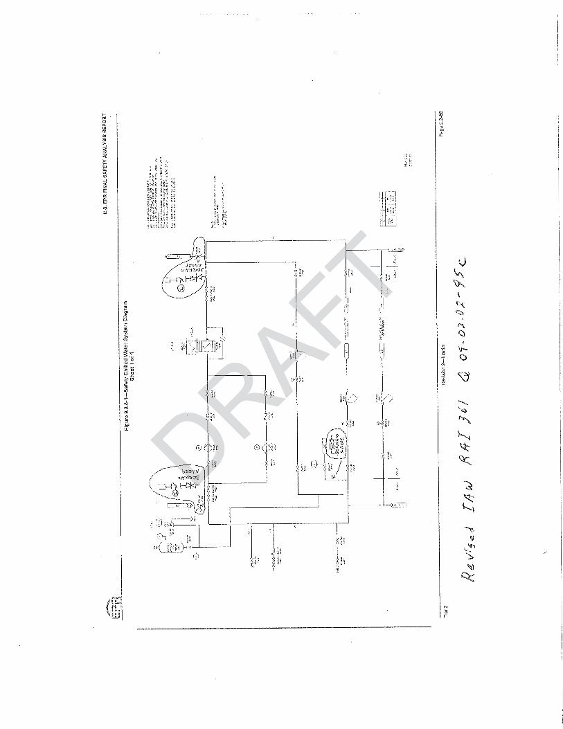
d. Add the SCWS flow direction arrows to the Figure 9.2.8-1 (Sheets 1 through 4), “Safety Chilled Water Diagram,” to confirm the directional flows in various sections of pipe under both independent and cross-tie alignments.
Response to Question 09.02.02-95:
a. The last paragraph in U.S. EPR FSAR Tier 2, Section 9.2.8.3.2 will be revised to describe the alternate power supplies to the motor operated valves in more detail.
The N+2 concept described in U.S. EPR FSAR Tier 2, Section 9.2.8.4 does not apply due to the change to cross-tie design; therefore, the sentence will be deleted.
b. See above response.
c. FSAR Table 3.9.6-2, “In-service Valve Testing Program Requirements” is updated to include the motor-operated cross-tie valves. Also changes to the table include some large diameter valves that are changed from plug valves to butterfly valves, and some manually operated valves are added to the table. A check valve is added to each SCWS train demineralized water source connection to prevent backflow and/or contamination of the demineralized water system.
d. Refer to response to RAI 174 Supplement 5, Question 09.02.02-53, markup Figure 9.2.8-1 (Sheets 1 through 4). Flow direction arrows will be added where needed. The sheet-to-sheet continuation arrows provide an indication of flow direction. On sheets 1 through 4, the supply side is on the right and the return side is on the left. For cross-tie operation, flow can be in either direction in the cross-tie lines depending on which SCWS train is in operation. For example if SCWS Train 1 is the operating train in divisional pair 1 & 2, starting on sheet 1, approximately half the total flow is through Train 1 cross-tie
DRAFT
ed Water ed Wate power suppate powe
ower supplies are nower suppliens provided in the respons provided in the
lies in the Tier 2 portionlies in the Tier 2 portion
e Valve Testing Prograve Testine valves. e va
rows to the Figure 9.2.8s to the Figure 9.2.onfirm the directional flowhe directional flo
s-tie alignments. s-tie alignments.
2.02-95: 2.02-
ph in U.S. EPR FSAR Tph in U.S. EPRlternate power supplieslternate power sup
oncept described in Uoncept described ange to cross-tieange to cross-t
se. se.

AREVA NP Inc.
Response to Request for Additional Information No. 361, Supplement 1 U.S. EPR Design Certification Application Page 3 of 3
supply valve 30QKA10AA102 (continuation to sheet 2) then through Train 2 cross-tie supply valve 30QKA20AA102, and then to Division 2 user heat exchangers. Similarly, on the return side, starting on Sheet 2, return flow is from the Division 2 user heat exchangers through the Train 2 cross-tie return valve 30QKA20AA103 (continuation to sheet 1) then through Train 1 cross-tie return valve 30QKA10AA103 and then to the suction side of the Train 1 pumps. As shown on sheet 1, on the supply side, the other approximate half of the total flow goes to the Division 1 user heat exchangers and returns to the suction side of the Train 1 pumps.
FSAR Impact:
a. U.S. EPR FSAR Tier 2, Section 9.2.8.3.2 will be revised as described in the response and indicated in the attached markup.
b. See a. above.
c. U.S. EPR FSAR Tier 2, Table 3.9.6-2, “In-service Valve Testing Program Requirements” will be revised as described in the response and indicated in the attached markup. Also U.S. EPR FSAR Tier 1, Figure 2.7.2-1 – Safety Chilled Water System Functional Arrangement, Sheets 1 – 4 will be revised and U.S. EPR FSAR Tier 2, Figure 9.2.8-1 – Safety Chilled Water System Diagram, Sheets 1 and 2 will be revised.
d. U.S. EPR FSAR Tier 2, Figure 9.2.8-1 (Sheet 2) will be revised as described in the response and indicated in the attached markup. AF
Trvice Varvice Valve Testinglve d in the response andd in the response
Tier 1, FiTier 1, Figure 2.7.2-1gure 2.7.2-1ent, Sheets 1 – 4 will bt, Sheets 1
– Safety Chilley Chill
DRA
d Wate
e 9.2.8-1 (Sheet 2) will 1 (Sheet 2) wilthe attached markup. the attached mar

Table 9.2.8-4-- Safety Chilled Water System Failure Analysis Sheet 1 of 4
Component Component Function Failure Mode Failure
Mechanism Failure Symptoms/Effect Can SCWS Satisfy Mission Success Criteria? Notes (1), (2), (3), (4) Yes. If SCWS Train 1 is out for maintenance (see Note 3 typical) and a failure occurs in Train 2, there is a second SCWS cross-tied pair Trains 3 & 4 that serves its associated user exchangers. Cooling function remains for Div 3 and 4.
SCWS 30QKA
Supply Chilled Water to User Exchangers
Passive failure, leak > makeup can handle
Mechanical System pressure falls below minimum requirement. Yes. If SCWS Train 1 is out for maintenance and a failure occurs in Train 4, train 2 would remain supplying Div 1 and 2 user exchangers. Cooling function remains for Div 1 and 2.
Train 3 can be administratively operated in independent division operation. Shut down 4. If this is performed along with the above, cooling function remains for Div 1, 2, and 3. YES. For cross-tie operation, two expansion tanks are inter-connected by the cross-tie. Each expansion tank serves two SCWS divisions. If SCWS Train 1 is out for maintenance and a failure occurs in Train 2 tank, there is a second SCWS cross-tied pair Trains 3 & 4 that serves its associated user exchangers. Cooling function remains for Div 3 and 4.
SCWS Expansion Tank30QKA10/20/30/40 BB101
Maintains pressure in the system.
Tank diaphragm fails to maintain system pressure or loss of nitrogen pressure
Mechanical/I&C System pressure falls below minimum requirement. YES. For cross-tie operation, two expansion tanks are inter-connected by the cross-tie. Each expansion tank serves two SCWS divisions. If SCWS Train 1 is out for maintenance and a failure occurs in Train 4 tank, cooling function remains for Div 1 and 2 served by Train 2 tank and cooling function remains for Div 3 and 4 served by Train 3 tank. Yes. If SCWS Train 1 is out for maintenance, and failure of one pump in Train 2 occurs, there is a second SCWS cross-tied pair 3 & 4 that serves its associated user exchangers. Cooling function remains for Div 3 and 4.
Train 2 can be administratively operated with one remaining pump in independent division operation. If this is performed along with the above, cooling function remains for Div 2, 3 and 4. Note (5)
SCWS Pump 30QKA10/20/30/40 AP107/108
Provides flow of water to each user.
Pump fails during normal operation
Mechanical,Electrical, I&C Loss of chilled water flow to the users.
Yes. If SCWS Train 1 is out for maintenance and failure of one pump in Train 4 occurs, standby Train 3 SCWS starts automatically which will continue to supply both Div 3 and 4. There is a second SCWS cross-tied pair 1 & 2 with SCWS Train 2 operating that serves Div 1 & 2 user exchangers. Cooling function remains for Div 1, 2, 3 and 4.
Yes. If SCWS Train 2 is out for maintenance, and failure of the chiller in Train 1 occurs, there is a second SCWS cross-tied pair 3 & 4 that serves its associated user exchangers. Cooling function remains for Div 3 and 4. Note (7) SCWS Air Cooled
Chiller 30QKA10/40 AH112 Note (6)
Transfers heat from the SCWS water to the refrigerant then transfers heat from the refrigerant to the air flow which is the heat sink for SCWS 1 and 4.
Chiller fails during normal operation.
Mechanical,Electrical, I&C
Loss of ability to provide chilled water at design temperature. Yes. If SCWS Train 1 is out for maintenance and failure of the chiller in Train 4 occurs,
standby Train 3 SCWS starts automatically which will continue to supply both Div 3 and 4. There is a second SCWS cross-tied pair 1 & 2 with SCWS Train 2 operating that serves Div 1 & 2 user exchangers. Cooling function remains for Div 1, 2, 3 and 4
SCWS Ventilation Equipment for Air Cooled Chiller 30QKA10/40
Transfer heat from SCWS 1 and 4 to Outside Air
Ventilation fails during normal operation
Mechanical,Electrical, I&C
Loss of ability to provide chilled water at design temperature. Yes. Bounded by above two items for the SCWS air cooled chiller.
RAFT
xchaxcha
t. t. Yes. If SCYesremain suppre
Train 3 can be admTrain 3 If this is performed is is peTFTYES. For cross-or crosEach expansinsiand a failuthat serFTFTlow minimum requirement. m require
DRA
YEEFF
RADLoss of chilled water flow to ts of chilled water flow to
DDDDDLoLo

Component Component Function Failure Mode Failure
Mechanism Failure Symptoms/Effect Can SCWS Satisfy Mission Success Criteria? Notes (1), (2), (3), (4) Yes. If SCWS Train 1 is out for maintenance, and failure of the chiller in Train 2 occurs, there is a second SCWS cross-tied pair 3 & 4 that serves its associated user exchangers. Cooling function remains for Div 3 and 4. Note (7) Loss of Division 2 of CCWS is equivalent to this case.
SCWS Water Cooled Chiller 30QKA20/30 AH112 Note (6)
Transfers heat from the SCWS water to the refrigerant then transfers heat from the refrigerant to Component Cooling Water System (CCWS) which is the heat sink for SCWS 2 and 3.
Chiller fails during normal operation.
Mechanical,Electrical, I&C
Loss of ability to provide chilled water at design temperature. Yes. If SCWS Train 1 is out for maintenance and failure of the chiller in Train 3 occurs,
standby Train 4 SCWS starts automatically which will continue to supply both Div 3 and 4. There is a second SCWS cross-tied pair 1 & 2 with SCWS Train 2 operating that serves Div 1 & 2 user exchangers. Cooling function remains for Div 1, 2, 3 and 4. Loss of Division 3 of CCWS is equivalent to this case.
Yes. If SCWS Train 1 is out for maintenance and failure occurs in Train 2 bypass valve, there is a second SCWS cross-tied pair 3 & 4 that serves its associated user exchangers. Cooling function remains for Div 3 and 4. Note (8)
Freezing the evaporator tubes Yes, If SCWS Train 1 is out for maintenance and a failure occurs in Train 4 bypass valve, automatically switch to the standby Train 3 in cross-tied pair 3 & 4. Train 2 would remain supplying Div 1 and 2 user exchangers. Cooling function remains for Div 1, 2, 3 and 4. Note (8)
Yes. If SCWS Train 1 is out for maintenance and a failure occurs in Train 2 bypass valve, there is a second SCWS cross-tie pair 3 & 4 that serves its associated user exchangers. Cooling function remains for Div 3 and 4.
Bypass Control Valve30QKA10/20/30/40 AA101
Prevents freezing of the evaporator tubes.
Does not modulate to desired position
Mechanical,Electrical, I&C
Valve inadvertently opens, bypassing too much flow. Either the operational division valve or stand-by division valve in each pair.
Yes, If SCWS Train 1 is out for maintenance and a failure occurs in Train 4 bypass valve, train 2 would remain supplying Div 1 and 2 user exchangers. Cooling function remains for Div 1 and 2.
Train 3 can be administratively operated in independent division operation. Shut down 4. If this is performed along with the above, cooling function remains for Div 1, 2 and 3. Yes. If SCWS Train 1 is out for maintenance and a failure occurs in Train 2 flow control valve, there is a second SCWS cross-tie pair 3 & 4 that serves its associated user exchangers. Cooling function remains for Div 3 and 4.
If the maintenance in SCWS Train 1 does not affect the Train 1 flow control valve 30QKC10AA101, cooling function remains for Div 1, 3 and 4.
Flow Control Valve for 30SAC01/02/03/04 AC001 Valve # 30QKC10/20/30/40 AA101
Controls flow through the HVAC cooling coil 30SAC01/02/03/04 AC001.
Does not modulate to desired position
Mechanical,Electrical, I&C
Loss of control of chilled water flow for the affected SAC exchanger in one division.
Yes, If SCWS Train 1 is out for maintenance and a failure occurs in Train 4 flow control valve, train 2 would remain supplying Div 1 and 2 user exchangers. Cooling function remains for Div 1 and 2. If failure of the Train 4 flow control valve 30QKC40AA101 does not affect overall SCWS operation, cooling function remains for Div 1, 2, 3 and 4 except for the affected SAC user exchanger.
If failure of the Train 4 flow control valve 30QKC40AA101 affects overall SCWS operation, Train 3 can be administratively operated in independent division operation. Shut down 4. If this is performed along with the above, cooling function remains for Div 1, 2 and 3.
AFT
anan4. The4. ThDiv 1 & 2DivLoss of DivisLoTYes. If SCWS Train. If SCWthere is a second s a secoCooling functiunctiTFTYes, If SautomsupFT
DRAFFT
AFve inadvertently opens, bypassing tve inadvertently opens, bypasflow. Either the operational divisionflow. Either the operational divisioby division valve in each pair. by division valve in each pair.
DDRD

Component Component Function Failure Mode Failure
Mechanism Failure Symptoms/Effect Can SCWS Satisfy Mission Success Criteria? Notes (1), (2), (3), (4) Yes. If SCWS Train 1 is out for maintenance and a failure occurs in Train 2 flow control valve, there is a second SCWS cross-tie pair 3 & 4 that serves its associated user exchangers. Cooling function remains for Div 3 and 4.
If the maintenance in SCWS Train 1 does not affect the Train 1 flow control valve 30QKB10AA101, cooling function remains for Div 1, 3 and 4. Flow Control Valve
for 30SAB01/02/03/04 AC001 Valve # 30QKB10/20/30/40 AA101
Controls flow through the HVAC cooling coil 30SAB01/02/03/04 AC001.
Does not modulate to desired position
Mechanical,Electrical, I&C
Loss of control of chilled water flow for the affected SAB exchanger in one SAB train.
Yes, If SCWS Train 1 is out for maintenance and a failure occurs in Train 4 flow control valve, train 2 would remain supplying Div 1 and 2 user exchangers. Cooling function remains for Div 1 and 2. If failure of the Train 4 flow control valve 30QKB40AA101 does not affect overall SCWS operation, cooling function remains for Div 1, 2, 3 and 4 except for the affected SAB user exchanger.
If failure of the Train 4 flow control valve 30QKB40AA101 affects overall SCWS operation, Train 3 can be administratively operated in independent division operation. Shut down 4. If this is performed along with the above, cooling function remains for Div 1, 2 and 3.
Flow Control Valve for LHSI Pump Seal Cooler Valve # 30QKA10/40 AA025
Controls flow through the LHSI pump seal cooler. Does not open. Mechanical,
Electrical, I&C Loss of chilled water flow for the affected LHSI pump in one division.
Yes, If SCWS Train 1 is out for maintenance and a failure occurs in Train 4 flow control valve, there are two CCWS divisions that serve LHSI pumps 2 & 3. Shutdown Div 4 LHSI pump. Div 1 and Div 2 user exchangers continue to be supplied from cross-tied pair 1 & 2 supplied by SCWS Train 2. Continue to operate cross-tied pair 3 and 4. Cooling function remains for Div 1, 2 and 3 LHSI pumps. For other user exchangers, cooling function remains for Div 1, 2, 3 and 4.
Fail open Mechanical,Electrical, I&C
Prevents independent divisional operation which requires cross-tie valves to be closed.
Yes, the associated cross-tie valve in the divisional pair, which is in series with the affected valve, remains closed. No effect on cooling function. Yes. If SCWS Train 1 is out for maintenance and a cross-tie valve fails closed in Train 2, there is a second SCWS cross-tie pair 3 & 4 that serves its associated user exchangers. Cooling function remains for Div 3 and 4.
Train 2 can be administratively operated in independent division operation. If this is performed along with the above, cooling function remains for Div 2, 3 and 4.
Cross-tie Valves 30QKA10/20/30/40AA102
Connect supply side of SCWS Div 1 to Div 2 and Div 3 to Div 4.
Fail closed Mechanical,Electrical, I&C
Prevents cross-tie operation which requires cross-tie valves to be open. Yes. If SCWS Train 1 is out for maintenance and a cross-tie valve fails closed in Train 4,
there is a second SCWS cross-tie pair 1 & 2 that serves its associated user exchangers. Cooling function remains for Div 1 and 2.
Trains 3 and 4 can be administratively operated in independent division operation. If this is performed along with the above, cooling function remains for Div 1, 2, 3 and 4.
Fail open Mechanical,Electrical, I&C
Prevents independent divisional operation which requires cross-tie valves to be closed.
Yes, the associated cross-tie valve in the divisional pair, which is in series with the affected valve, remains closed. No effect on cooling function.
Cross-tie Valves 30QKA10/20/30/40AA103
Connect return side of SCWS Div 1 to Div 2 and Div 3 to Div 4
Fail closed Mechanical,Electrical, I&C
Prevents cross-tie operation which requires cross-tie valves to be open.
Yes. If SCWS Train 1 is out for maintenance and a cross-tie valve fails closed in Train 2, there is a second SCWS cross-tie pair 3 & 4 that serves its associated user exchangers. Cooling function remains for Div 3 and 4.
Train 2 can be administratively operated in independent division operation. If this is performed along with the above, cooling function remains for Div 2, 3 and 4.
RAFT
esesvalve, tvalveremains foremnot affect ovnofor the affected for th
If failure of the Trailure ofoperation, Train on, TraShut down 4. n 41, 2 and 3. FTer flow for the affected LHSI flow for the affected LHSI
vision.
Yes, va
AFT
DRAFT
ents independent divisional operatioents independent divisional equires cross-tie valves to be closedequires cross-tie valves to be closRARADanical,anical,
al, I&C al, I&CPrevents cross-tients cross-tietie valves to beves DD

Component Component Function Failure Mode Failure
Mechanism Failure Symptoms/Effect Can SCWS Satisfy Mission Success Criteria? Notes (1), (2), (3), (4) Yes. If SCWS Train 1 is out for maintenance and a cross-tie valve fails closed in Train 4, there is a second SCWS cross-tie pair 1 & 2 that serves its associated user exchangers. Cooling function remains for Div 1and 2
Trains 3 and 4 can be administratively operated in independent division operation. If this is performed along with the above, cooling function remains for Div 1, 2, 3 and 4.
SAC HVAC Cooling Coils Heat transfer via SCWS.
Clogged tubes/structural degradation/tube rupture
Mechanical Loss of heat transfer capabilities. YES. Bounded by passive failure indicated in first item of this table.
SAB HVAC Cooling Coils Heat transfer via SCWS.
Clogged tubes/structural degradation/tube rupture
Mechanical Loss of heat transfer capabilities. YES. Bounded by passive failure indicated in first item of this table.
KLC HVAC Cooling Coils Heat transfer via SCWS.
Clogged tubes/structural degradation/tube rupture
Mechanical Loss of heat transfer capabilities. YES. Bounded by passive failure indicated in first item of this table.
KLL HVAC Cooling Coils Heat transfer via SCWS.
Clogged tubes/structural degradation/tube rupture
Mechanical Loss of heat transfer capabilities. YES. Bounded by passive failure indicated in first item of this table.
LHSI Pump Motor and Seal Coolers 30JNG10/40 AP001
Heat transfer via SCWS.
Clogged tubes/structural degradation/tube rupture
Mechanical
Loss of heat transfer capabilities. For LHSI pump seal cooler, tube rupture could result in contamination of SCWS. Radiation monitor will detect contamination.
YES. Bounded by passive failure indicated in first item of this table.
Notes: 1. This analysis considers safety chilled water system (SCWS) with loss of off-site power (LOOP) and one SCWS train unavailable due to maintenance with normal cross-tie operation.
2. Mission success requires, for all modes of operation, that SCWS supply chilled water to two divisions of SAC, SAB, and KLC; one division of KLL; and along with component cooling water system, supply two LHSI pumps motor and seal cooler.
3. One SCWS train is assumed to be out for maintenance with the following components out of service: SCWS chiller unit and/or two pumps. 4. SCWS Trains 1 and 4 are essentially identical. SCWS Trains 2 and 3 are essentially identical. The chilled water circuits of all four SCWS trains are essentially identical except for the HVAC user exchangers served. Therefore,
this analysis will identify the identical components in the “Component” column and populate the table once. 5. In cross-tie operation two pumps in the operating train of each divisional pair provides flow to 2 user divisions. One pump in independent division operation provides flow to its division.
6. The chiller unit for each SCWS train includes the condenser, evaporator, compressors, and other refrigerant system components. 7. If failure is limited to one compressor, there is redundancy in the compressor units provided by three 50% capacity compressor units in each train. Two compressor units provide the design capacity for each SCWS train. The
affected train can be administratively operated with the two remaining compressors. 8. In cross-tie operation the SCWS bypass valve in the operating train of each divisional pair provides the bypass function. The bypass valve in the standby division of each pair is automatically closed.
YES. BoYES
TYES. Bounded by pS. BounTFTilities. YES. BoFTFTansfer capabilities. pabilities. AFFDRAof heat transfer capabilities. of heat transfer capabilitie
r LHSI pump seal cooler, tube ruptur LHSI pump seal cooler, tube result in contamination of SCWS. Rresult in contamination of SCWS.
DRmonitor will detect contaminatiomonitor will detect contaminatioRADDDR
ss of off-site power (LOOP) and ss of off-site power (LOOP) supply chilled watesupply chilled water to two divisr to two divisDlowing components out olowing components o
are essentially idenare essentially ideolumn and popolumn and pop
ir providir provid


Response to
Request for Additional Information No. 361, Supplement 1
3/04/2010
U.S. EPR Standard Design Certification AREVA NP Inc.
Docket No. 52-020 SRP Section: 09.02.02 - Reactor Auxiliary Cooling Water Systems
Application Section: 09.02.08
QUESTIONS for Balance of Plant Branch 1 (AP1000/EPR Projects) (SBPA)
DRAFT
1000/EPR 1000/

AREVA NP Inc.
Response to Request for Additional Information No. 361, Supplement 1 U.S. EPR Design Certification Application Page 2 of 2
Question 09.02.02-102:
Follow-up to RAI 174, Question 09.02.02-53
The safety chilled water system (SCWS) must be capable of removing heat from structures, systems and components (SSCs) important to safety during normal operating and accident conditions over the life of the plant in accordance with general design criteria (GDC) 44 requirements. Under seismic or post-accident conditions with the demineralized water unavailable for safety chilled water system (SCWS) makeup, the expansion tanks should contain sufficient water volume to assure reliable system operation without makeup for at least seven days. Based on the staff’s review of the applicant’s response to RAI 174, Question 9.2.2-53, Supplement 5 and information provided in the associated markup of the Final Safety Analysis Report (FSAR), Section 9.2.8, “Safety Chilled Water System” the staff found a significant design change to the system. The safety chilled water system (SCWS) design now utilizes “cross-ties” between Trains 1 and 2 and between Trains 3 and 4, instead of the independent four-train system structure utilized in the original design. In the cross-tied configuration, the staff requests the applicant describe whether the expansion tank in the non-operating train is isolated from the system. If not, address precluding of the SCWS design from the sluicing of water between the two expansion-tanks as system loads cycle (or on trip of a chiller and start of the standby unit) and describe the tanks volume requirements to account for sluicing. If isolated, describe the operation of the expansion tank isolation valves during operation and accident conditions.
Response to Question 09.02.02-102:
In cross-tie operation, the expansion tank in the standby train is not mechanically isolated.
Sluicing is not significant because the two cross-tied expansion tanks are not close together. One tank is in one Safeguard Building and the other tank in the pair is in another Safeguard Building. The cross-tied expansion tanks are not at the same elevation. Train 2 tank is several floor elevations lower than Train 1 tank. Train 3 tank is several floor elevations lower than Train 4 tank. The pipe size (2 inches) connecting each tank to the system is small relative the system pipe size. The elastomeric material of the expansion tank diaphragm and the compressed nitrogen confined above the diaphragm have a dampening effect on pressure pulsations in the system. Should momentary instability between two cross-connected expansion tanks occur, the instability would be dampened quickly due to the effects of the diaphragm, the compressed nitrogen, resistance of the long length of piping between tanks and resistance of the small diameter piping at the tank connection.
Refer to information concerning sizing of expansion tank in the response to RAI 356, Question 09.02.02-91.
FSAR Impact:
The U.S. EPR FSAR will not be changed as a result of this question.
DRAFT
stesteter syster sy
ains 3 and 4ains 3inal design. In thinal design
whether the expansiowhether the expddress precluding of theddress precluding of t
anks as system loads canks as system loads cbe the tanks volume reqthe tanks vo
of the expansion tank isopansio
2:
nsion tank in nsion tank the standbe st
ecause the two cross-tiause the two cross-tiguard Building and the oguard Building
DRed expansion tanks areed expansion tanks
er than Train 1 tank. Trer than Train 1 tank. Tze (2 inches) connecze (2 inches) con
meric material omeric material Dthe diaphthe diaphy insty inst

Response to
Request for Additional Information No. 406(4683, 4664, 4707), Revision 0
6/16/2010
U. S. EPR Standard Design Certification AREVA NP Inc.
Docket No. 52-020 SRP Section: 09.02.02 - Reactor Auxiliary Cooling Water Systems
SRP Section: 09.04.01 - Control Room Area Ventilation System SRP Section: 09.05.01 - Fire Protection Program
Application Section: FSAR Chapter 9
QUESTIONS for Balance of Plant Branch 1 (AP1000/EPR Projects) (SBPA) QUESTIONS for Containment and Ventilation Branch 1 (AP1000/EPR Projects) (SPCV)
QUESTIONS for Balance of Plant Branch 1 (SBPA)FThapter 9 hapte
(AP1000/EPR Projec(AP1000/EPR PBranch 1 (AP1000/EPRBranch 1 (AP1000/EP
DRAFTof Plant Branch 1 (SBf Plant Bran
AREVA NP Inc.
Response to Request for Additional Information No. 406 U.S. EPR Design Certification Application Page 2 of 7
Question 09.02.02-110:
Follow-up to RAI 334, Question 9.2.2-62 and RAI 174, Question 9.2.2-13
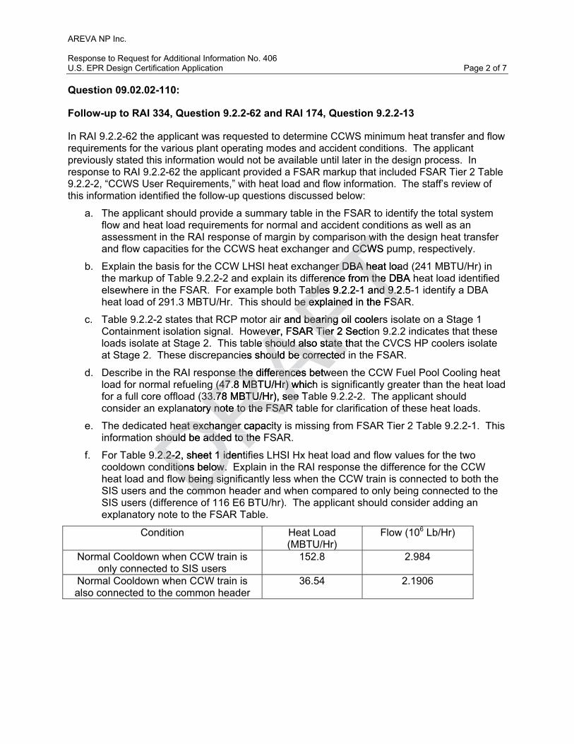
In RAI 9.2.2-62 the applicant was requested to determine CCWS minimum heat transfer and flow requirements for the various plant operating modes and accident conditions. The applicant previously stated this information would not be available until later in the design process. In response to RAI 9.2.2-62 the applicant provided a FSAR markup that included FSAR Tier 2 Table 9.2.2-2, “CCWS User Requirements,” with heat load and flow information. The staff’s review of this information identified the follow-up questions discussed below:
a. The applicant should provide a summary table in the FSAR to identify the total system flow and heat load requirements for normal and accident conditions as well as an assessment in the RAI response of margin by comparison with the design heat transfer and flow capacities for the CCWS heat exchanger and CCWS pump, respectively.
b. Explain the basis for the CCW LHSI heat exchanger DBA heat load (241 MBTU/Hr) in the markup of Table 9.2.2-2 and explain its difference from the DBA heat load identified elsewhere in the FSAR. For example both Tables 9.2.2-1 and 9.2.5-1 identify a DBA heat load of 291.3 MBTU/Hr. This should be explained in the FSAR.
c. Table 9.2.2-2 states that RCP motor air and bearing oil coolers isolate on a Stage 1 Containment isolation signal. However, FSAR Tier 2 Section 9.2.2 indicates that these loads isolate at Stage 2. This table should also state that the CVCS HP coolers isolate at Stage 2. These discrepancies should be corrected in the FSAR.
d. Describe in the RAI response the differences between the CCW Fuel Pool Cooling heat load for normal refueling (47.8 MBTU/Hr) which is significantly greater than the heat load for a full core offload (33.78 MBTU/Hr), see Table 9.2.2-2. The applicant should consider an explanatory note to the FSAR table for clarification of these heat loads.
e. The dedicated heat exchanger capacity is missing from FSAR Tier 2 Table 9.2.2-1. This information should be added to the FSAR.
f. For Table 9.2.2-2, sheet 1 identifies LHSI Hx heat load and flow values for the two cooldown conditions below. Explain in the RAI response the difference for the CCW heat load and flow being significantly less when the CCW train is connected to both the SIS users and the common header and when compared to only being connected to the SIS users (difference of 116 E6 BTU/hr). The applicant should consider adding an explanatory note to the FSAR Table.
Condition Heat Load (MBTU/Hr)
Flow (106 Lb/Hr)
Normal Cooldown when CCW train is only connected to SIS users
152.8 2.984
Normal Cooldown when CCW train is also connected to the common header
36.54 2.1906
DRAFT
n wn wd CCWS pd CCW
er DBA heat loader DBA heerence from the DBA herence from the
ables 9.2.2-1 and 9.2.5-ables 9.2.2-1 and 9.2be explained in the FSAbe explained in the FSA
r and bearing oil cooler bearing ver, FSAR Tier 2 Sectiover, FSAR Tier
le should also state thashould also state tes should be corrected ould be corrected
se the differences betwse the differences betw (47.8 MBTU/Hr) which (47.8 MBTU/Hr) w
(33.78 MBTU/Hr), see T33.78 MBTU/Hr), seeatory note to the FSAR ry note to the FSAR
heat exchanger capacitheat exchanger c
DRhould be added to the hould be added to th
.2.2-2, sheet 1 identi.2.2-2, sheet 1 idditions below. Editions below.
w being siw being siDcommcomm

AREVA NP Inc.
Response to Request for Additional Information No. 406 U.S. EPR Design Certification Application Page 3 of 7
Response to Question 09.02.02-110:
a. A review of the CCWS confirmed the system heat load and user flow requirements for normal and accident conditions. The following table summarizes the heat load and flow requirements used for determining the heat exchanger design case. Note that the CCWS user flow listed in this table is the total flow that exits the CCWS heat exchanger and is distributed to the users. This is not the total pump discharge flow.
Due to variations in heat load, required flow and “U” for each CCWS operational alignment, the combined “UA” value is used to determine the design case for each CCWS heat exchanger. The design parameters for these operational cases will be provided to the heat exchanger vendor. The vendor will factor these system parameters into the design of the heat exchanger with the design constraint that the heat exchanger must meet the highest required combined “UA” of all cases. The vendor will determine the best combination of “U” and “A” to meet these requirements. By meeting this requirement for the highest required combined “UA”, the heat exchanger design will have margin for all other operational alignments. The DBA cases assume an ESW inlet temperature of 95°F with a CCWS outlet temperature of 110°F. The value of 110°F is used to account for instrument uncertainty in the maximum allowed CCWS outlet temperature of 113°F. The RCS cooldown cases assume an ESW inlet temperature of 90°F with a CCWS outlet temperature of 99.2°F. The RCS heatup cases assume an ESW inlet temperature of 92°F with a CCWS outlet temperature of 99.2°F. The value of 99.2°F is used to account for instrument uncertainty in the maximum allowed CCWS outlet temperature of 100.4°F for normal operations cases. No correction factor is assumed in the LMTD calculations.
CCWS Operational Alignment Reqd Heat
Transfer (106
BTU/hr)
CCWS User Flow (106
lbm/hr)
ESWSFlow (106
lbm/hr)LMTD(°F)
UA (106
BTU/hr-°F)
RCS Cooldown; CCWS Train Not Connected to a Common Header
153.1 3.061 7.54 20.60 7.43
RCS Cooldown; CCWS Train 1 or 2 Connected to Common 1 Plus Train Specific SIS Users
118.4 7.071 7.54 9.71 12.19
RCS Cooldown; CCWS Train 3 or 4 Connected to Common 2 Plus Train Specific SIS Users
124.9 7.055 7.54 9.76 12.79
RCS Heatup; CCWS Train 1 or 2 Connected to Common 1 106.8 5.624 7.54 9.41 11.35
RCS Heatup; CCWS Train 3 or 4 Connected to Common 2 123.4 5.802 7.54 9.44 13.07
DBA - CCWS Train 1 or 2 aligned to Common 1 Header 291.8 4.299 7.54 27.01 10.80
DBA - CCWS Train 3 or 4 aligned to Common 2 Header 291.4 4.278 7.54 27.12 10.74
DRAFT
ttmbinedmbine
and “A” to and r the highest requr the highe
for all other operationfor all other opeature of 95°F with a CCature of 95°F with a
0°F is used to account 0°F is used to account CCWS outlet temperatCWS outlet
W inlet temperature of 90mperaCS heatup cases assumCS heatup cases a
mperature of 99.2°F. Trature of 99.2°F. Tcertainty in the maximuy in the maximu
F for normal operations F for normal operaD calculations. D calculat
ignment ignment Reqd Heat Req
Transfer (10TransfeBTU/hrTU/hDRDRWS Train WS Tr
mmon mmon 1DRDRn 1 n 1 DD

AREVA NP Inc.
Response to Request for Additional Information No. 406 U.S. EPR Design Certification Application Page 4 of 7
The highest required combined “UA” of 13.07E+06 BTU/hr-°F results from RCS Heatup; CCWS Train 3 or 4 Connected to Common 2. This case yields the highest required combined “UA” due to low temperature deltas in the system during this operational alignment. The LMTD for this case is calculated with an ESWS inlet temperature of 92°F and a CCWS outlet temperature of 99.2°F for normal operations. 99.2°F is used to account for instrument uncertainty in the maximum allowed CCWS outlet temperature of 100.4°F. An example area calculation for this case assuming a U of 360 BTU/hr*ft2*°F yields a required area of 36,311 ft2.Considering a 10% margin for tube plugging, the heat exchanger design area for this example case becomes 39,942 ft2. The design of the CCWS heat exchanger will require a minimum additional margin of 10 percent above the specified 10 percent tube plugging allowance.
Calculation of UA values for different modes of heat exchanger operation provides a reasonable initial basis for comparison prior to selection of a final heat exchanger design. However, the physical parameter of heat transfer area required for each case would provide a much more accurate basis for comparison. The required area cannot be reliably determined without detailed heat exchanger design information necessary to support calculation of the overall heat transfer coefficient (U), which will vary for each case. Operating modes for the CCWS with the highest UA value also have significantly higher CCW flow rates. Higher flow rates will increase U and actually require lower heat transfer area thus changing design margin comparisons based solely on UA values. Since this information will not be known until final procurement, the DBA case will require a minimum additional margin of 10 percent above the specified 10 percent tube plugging allowance. This will provide assurance that adequate safety margin in provided for the DBA case irrespective of the final CCWS heat exchanger design.
A review of the CCWS confirmed the highest required pump discharge flow results from any of the trains connected to either of the common headers during normal operation. This normal operation alignment has all CCWS users connected simultaneously (including SIS users). The following table summarizes the pump discharge flow requirements used for determining the pump design flow rate. Note that the CCWS pump discharge flow listed in this table is the total flow through the pump. This flow includes flow through the 4 inch surge tank recirculation line that does not go through the CCWS heat exchanger. In addition to the recirculation flow, the normal operations flow requirement for the CVCS HP coolers is greater than the CVCS HP cooler required flow in the cooldown alignment. These factors result in a higher required total pump discharge flow as compared to the user required CCWS flow through the heat exchanger for heatup and cooldown cases.
The expected CCWS pump suction temperatures for the various operational alignments are enveloped by a temperature of 190°F. The 190°F temperature is conservatively based on CCWS heat exchanger DBA inlet temperature (181°F) plus margin. The 181°F DBA inlet temperature would be a result of water exiting the CCWS heat exchanger at the maximum allowed outlet temperature of 113°F for DBA conditions. Using water at 190°F this converts to a required flow of 15570 gpm. Applying the pump margin of 15.33% from the Response to RAI 334, Question 9.2.2-
eat exchangeat exselection of a finselection
f heat transfer area ref heat transfer ate basis for comparisonte basis for comparis
detailed heat exchangedetailed heat exchangethe overall heat transferoverall hea
odes for the CCWS withthe Cflow rates. Higher flow low rates. Higher
ransfer area thus changfer area thus chans. Since this informatioe this informati
case will require a minicase will require 10 percent tube pluggin10 percent tube plu
ety margin in provided fety margin in providedchanger design. nger design.
of the CCWS confirmedof the CCWS confirm
Dy of the trains connectey of the trains connecten. This normal opern. This normal o
usly (includingusly (includinw requiremw requirem
pumpum

AREVA NP Inc.
Response to Request for Additional Information No. 406 U.S. EPR Design Certification Application Page 5 of 7
63 to the highest required pump discharge flow of 15570 gpm results in a design pump flow of 17957 gpm.
CCWS Operational Alignment CCWS Pump Discharge Flow (106 lbm/hr)
CCWS Pump Discharge Flow (gpm)
Normal Operation; CCWS Train 1 or 2 Connected to Common 1 Plus Train Specific SIS Users 7.359 15203
Normal Operation; CCWS Train 3 or 4 Connected to Common 2 Plus Train Specific SIS Users 7.537 15570
DBA - CCWS Train 1 or 2 aligned to Common 1 Header 4.407 9104
DBA - CCWS Train 3 or 4 aligned to Common 2 Header 4.386 9061
A pump design flow rate of 17957 gpm provides margin for operational alignments where the total user required flow is less than 15570 gpm. The following table summarizes the margin in the CCWS pump flow for normal operations and DBA cases.
CCWS Operational Alignment CCWS Pump
Discharge Flow (gpm)
Pump Design Flow (gpm)
Margin in Pump Flow
(%) Normal Operation; CCWS Train 1 or 2 Connected to Common 1 Plus Train Specific SIS Users
15203 18
Normal Operation; CCWS Train 3 or 4 Connected to Common 2 Plus Train Specific SIS Users
15570 15
DBA - CCWS Train 1 or 2 aligned to Common 1 Header 9104 97
DBA - CCWS Train 3 or 4 aligned to Common 2 Header 9061
17957
98
The surge tank recirculation line flow has no effect on the heat transfer margins of the CCWS heat exchangers. The surge tank recirculation flow is included in the pump flow design case. The surge tank recirculation flow does not go through the CCWS heat exchanger to be distributed to CCWS users, therefore that flow is not used in the heat exchanger design case and margin calculations. For the heat exchanger design case and margin calculations, only the CCWS user flows are considered.
U.S. EPR FSAR, Tier 2, Tables 9.2.2-1 and 9.2.2-2 will be revised to update the CCWS flow requirements. Tier 2 Tables 9.2.2-6 and 9.2.2-7 will be added to summarize CCWS heat load and flow requirements for various operational alignments. U.S. EPR FSAR Tier 2, Section 9.2.2 will be revised to include the heat transfer and pump discharge flow margins for the DBA case.
b. A review of the CCWS confirmed the CCWS LHSI heat exchanger DBA heat load of 241 MBTU/hr. The LHSI heat exchanger DBA heat load of 241 MBTU/hr is the
RAFTTmargin for opmargin
15570 gpm. The f15570 gpmp flow for normal operap flow for normal
CCWS Pump S PumDischarge Flow Discharge Flow
(gpm)(gpm)AFAFSpecific Specific 15203 ADRARA3 or 4 3 or 4
s Train Specific rain Specific RARA2 aligned to 2 aligned to
DRRDR3 or 4 aligned to 3 or 4 aligned to DRDk recircuk recircuexcexc

AREVA NP Inc.
Response to Request for Additional Information No. 406 U.S. EPR Design Certification Application Page 6 of 7
decay heat removed by the LHSI system to the CCWS heat exchanger. The MHSI and LHSI pump heat loads are specifically listed as individual values in FSAR Table 9.2.2-2. U.S EPR FSAR Tier 2, Table 9.2.2-1 and 9.2.5-1 will be revised to update the CCWS DBA heat load that is applied to the Ultimate Heat Sink.
A review of the CCWS design confirmed the CCWS heat exchanger DBA heat load on the Ultimate Heat Sink (UHS) of 291.8 MBTU/hr. This heat load is equal to the LHSI heat exchanger DBA heat load of 241 MBTU/hr from Table 9.2.2-2 plus the additional loads from the CCWS common header users aligned during a DBA. The value of 291.8 MBTU/hr in Tables 9.2.2-1 and 9.2.5-1 is the total DBA heat load that the CCWS is required to reject to the UHS. The design of the UHS is required to account for this CCWS heat load plus any additional DBA heat loads that directly impact the UHS. Refer to U.S. EPR FSAR Section 9.2.5 for a discussion on the UHS design. The following table summarizes the CCWS user loads for the DBA condition (the limiting DBA case results from Train 1 or 2 aligned to Common 1).
Reqd HT
Designation of equipment percomp per train
Name KKS
# of comp/train 106
BTU/hr 106
BTU/hr
CCWS pump MAC KAA10/20AC002 1 0.0955 0.0955
LHSI hx JNG10/20 AC001 1 241.0 241.0
LHSI pump MAC JNG10/20 AP001 1 0.1262 0.1262LHSI seal fluid cooler JNG10/20 AP001 1 0.0341 0.0341MHSI pump MAC JND10/20 AP001 1 0.0239 0.0239Charging pump motor air cooler KBA31 AP001 1 0.1706 0.1706
Charging pump oil cooler KBA31 AP001 1 0.1706 0.1706Charging pump seal water cooler KBA31 AP001 1 0.1706 0.1706
CVCS HP cooler KBA11 AC001 1 6.9 6.9RCP lower bearing oil cooler JEB10/20 AC001 2 0.0819 0.1638
RCP motor air cooler JEB10/20AC002/003 4 1.075 4.3
RCP thermal barrier N/A 4 0.3915 1.566RCP upper bearing oil cooler JEB10/20 AC004 2 1.305 2.61
Nuke Sample Coolers KUA20/30AC001 2 0.3958 0.7916
QKA Chiller QKA20 AC001 1 4.123 4.123SFP heat exchanger FAK20 AC001 1 29.00 29.00
SG Sample Coolers QUC11/12 AC001 2 0.2593 0.5186
Sum 291.8
RAFT
2.2.CCWS uCCWS
n 1 or 2 align 1 o
Reqd HT d HT
FTFperpecompc peFTAFT# of of
comp/trainain 106
BTU/hrB
AFAAF11 0.00.0AFRAAF
0 11
RADRARAA10/20 AP00110/20 AP001 11RARANG10/20 AP001G10/20 AP001 11RARAJND10/20 AP001 JND10/20 A
DRDRDRair air KBA31 AP001 A31 AP001 DRDRooler ooler KBA31 AP001APDDDKBA31 APKBA31 ADDDBA1BA1D

AREVA NP Inc.
Response to Request for Additional Information No. 406 U.S. EPR Design Certification Application Page 7 of 7
U.S EPR FSAR Tier 2, Table 9.2.5-1 will be revised to update the CCWS heat exchanger DBA heat load.
c. Refer to the Response to part (a) of RAI 406, Question 9.2.2-110 for the update of U.S. EPR FSAR Table 9.2.2-2.
d. Refer to the Response to part (a) of RAI 406, Question 9.2.2-110 for the update of U.S. EPR FSAR Table 9.2.2-2.
e. A review of the CCWS confirmed the Dedicated CCWS Heat Exchanger capacity of 51.2 MBTU/hr. The value of 50.5 MBTU/hr listed in 9.2.2-2 is only the SAHRS heat exchanger heat load on the Dedicated CCWS train. The Dedicated CCWS heat exchanger design parameter of 51.2 MBTU/hr includes the additional SAHRS pump cooler loads that are directly cooled by the Dedicated CCWS.
f. Refer to the Response to part (a) of RAI 406, Question 9.2.2-110 for the update of U.S. EPR FSAR Table 9.2.2-2.
FSAR Impact:
U.S. EPR FSAR, Tier 2 Table 9.2.2-1, 9.2.2-2 and 9.2.5-1 will be revised as described in the response and indicated on the enclosed markup.
U.S. EPR FSAR, Tier 2 Section 9.2.2.2.1 will be revised as described in the response and indicated on the enclosed markup.
U.S. EPR FSAR, Tier 2 Tables 9.2.2-6 and 9.2.2-7 will be added as described in the response and indicated on the enclosed markup. RA
FTed CCWed CC
Question 9.2.2-11Question 9
2 and 9.2.5-1 will be rev.2.5-1 warkup. arkup
.2.1 will be revised as dll be revised as d
DRAs 9.2.2-6 and 9.2.2-7 ws 9.2.2-6 and 9.2.2-7
sed markup. d markup.


FSAR Section 9.2.2.2.1 Insert for RAI 406; 9.2.2-110
During normal operation the temperature at the outlet of the CCWS heat exchanger must be greater than 59°F and lower than 100.4°F. During a DBA, the CCWS heat exchanger outlet temperature must be lower than 113°F.
The expected CCWS pump suction temperatures for the various operational alignments are enveloped by a temperature of 190°F. The 190°F temperature is conservatively based on CCWS heat exchanger DBA inlet temperature (181°F) plus margin. The 181°F inlet temperature results from a maximum allowed CCWS heat exchanger outlet temperature of 113°F for DBA conditions.
DRAFT


RAI 406, Q 9.2.2-110 FSAR Insert 'A'
Component KKS
Heat Load (106
BTU/hr)
RequiredFlow (106
lbm/hr)
CCWS Pump Motor Cooler KAA10/40 AC002 0.0955 0.0302
152.8 2.984
36.54 2.1906
241 2.1906
MHSI Pump Motor Cooler JND10/40 AP001 0.0239 0.0265
CCWS Pump Motor Cooler KAA20/30 AC002 0.0955 0.0302
152.8 2.984
36.54 2.1906
241 2.1906
MHSI Pump Motor Cooler JND20/30 AP001 0.0239 0.0265
LHSI Pump Motor Cooler JNG20/30 AP001 0.1262 0.0141
LHSI Sealing Fluid Cooler JNG20/30 AP001 0.0341 0.0062
29 0.881867.62 2.645
Safety Chiller QKA20 AC002 4.123 0.373RCP Thermal Barrier N/A 1.566 0.0792
Additional Operational Users
QNA, QNB, JEB, KBA, KLA, KTA, QUC, KUA
69.86 4.11
29 0.881847.8 2.645
Safety Chiller QKA30 AC002 4.123 0.373RCP Thermal Barrier N/A 1.566 0.0792
Additional Operational Users
QNA, QNB, JEB, KBA, QUC, KUA, LCQ, KBF, KBG, KPC, KPF
86.29 4.29
Severe Accident Heat Removal System Heat Exchanger
JMQ40 AC001/004 50.5 1.104
Notes:
Thermal Barriers 1-4 can be cooled by
Dedicated CCWS Train
1. A CCWS train aligned only to the train SIS users has a higher heat removal capacity than a CCWS train that is also aligned to the Common header plus the CCWS train SIS users. Flow that would normally go to the common header is used for additional heat removal capacity from the SIS users.
Normal Cooldown when CCW train is also connected to the CCW common header (1)
DBA
Comments
Normal Cooldown when CCW train is also connected to the CCW common header (1)
DBA
CCWS Main Trains 1 and 4
CCWS Main Trains 2 and 3
LHSI Heat Exchanger JNG10/40 AC001
Normal Cooldown when CCW train is only connected to the train SIS users (1)
Common Header 1Normal Operations
Table 9.2.2-2 - CCWS User Requirements Summary
Flow isolated when LHSI pump is out of service for dilution prevention
LHSI Heat Exchanger JNG20/30 AC001
Normal Cooldown when CCW train is only connected to the train SIS users (1)
RefuelingFuel Pool Cooling Hx FAK10 AC001
Thermal Barriers 1-4 can be cooled by
Common Header 2
Fuel Pool Cooling Hx FAK20 AC001 Normal OperationsRefueling
TTTormal Cooldownormal Co
DRAFT
DRRRAAF
DRRFTAFAFRARARDRDRDRDD
.19061906
2.1906
39 0.02650.0265
0.12620.126 0.01410.0
11 0.0341341 0.000.0
29267.6267.62
20 AC00220 A 4.1221
B, JEB, B, JETA, TA,
Normal Cooldownormal Cooldownconnected to thconn
DBAD
Common HeaCommon Hea
connected to the traiconnected to
AC001AC001

RAI 406, Q 9.2.2-110 FSAR Insert 'B'
Heat Load (106
BTU/hr)
106.8
123.4 (1)
118.4
124.9
153.1
291.8291.4
Notes:
Table 9.2.2-6 - CCWS Heat Load Summary
CCWS Operational Alignment
RCS Heat-up CCWS Train 1or 2 Connected to Common 1
RCS Heat-up CCWS Train 3 or 4 Connected to Common 2RCS Cooldown CCWS Train 1 or 2 Connected to Common 1 Plus Train Specific SIS UsersRCS Cooldown CCWS Train 3 or 4 Connected to Common 2 Plus Train Specific SIS UsersRCS Cooldown CCWS Trains Not Connected to a Common HeaderDBA - CCWS Train 1 or 2 aligned to Common 1 HeaderDBA - CCWS Train 3 or 4 aligned to Common 2 Header
1. Current analysis assuming a representative constant heat transfer coefficient indicates that 123.4 MBTU/hr combined with CCWS and ESWS flow rates will require the greatest heat transfer area for the CCWS heat exchanger. For final procurement a 10% margin for tube plugging will be required. The DBA case will require a minimum additional margin of 10% above the specified 10% tube plugging allowance.
DRAFTFFransfer
WS and WSrea for the a for the
% margin for tube n for tube re a minimum re a minimum
0% tube plugging 0% tube plugging

RAI 406, Q 9.2.2-110 FSAR Insert 'C'
CCWS Pump Discharge Flow (106 lbm/hr) (1)
CCWS Pump Discharge Flow
(gpm) (1)
7.359 15203
7.537 15570
4.407 9104
4.386 9061
Notes:
1. The total required pump flow in each alignment includes recirculation flow to each CCWS surge tank. The margins discussed in Section 9.2.2 are applied to the highest calculated required flow.Applying the margin to the largest calculated total flow requirement envelopes the required flow for all CCWS pumps in any operating mode.
Table 9.2.2-7 - CCWS Pump Flow Summary
CCWS Operational Alignment
Normal Operation; CCWS Train 1 or 2 Connected to Common 1 Plus Train Specific SIS UsersNormal Operation; CCWS Train 3 or 4 Connected to Common 2 Plus Train Specific SIS Users
DBA - CCWS Train 1 or 2 aligned to Common 1 Header
DBA - CCWS Train 3 or 4 aligned to Common 2 Header
FTTculation flow to each Cculation flow to
he highest calculated requhe highest calculated
DRAFTirement envelopes the reqirement envelopes the re


![2009/05/13 Areva EPR DC - Response to U.S. EPR Design ... · 1 ArevaEPRDCPEm Resource From: Pederson Ronda M (AREVA NP INC) [Ronda.Pederson@areva.com] Sent: Wednesday, May 13, 2009](https://static.fdocuments.in/doc/165x107/5fa83fe16f08fd68a6724bf1/20090513-areva-epr-dc-response-to-us-epr-design-1-arevaeprdcpem-resource.jpg)


![2011/07/06 Areva EPR DC - Response to U.S. EPR Design ... · 1 ArevaEPRDCPEm Resource From: WILLIFORD Dennis (AREVA) [Dennis.Williford@areva.com] Sent: Wednesday, July 06, 2011 3:47](https://static.fdocuments.in/doc/165x107/6016f56c1fbc8a5335319bdd/20110706-areva-epr-dc-response-to-us-epr-design-1-arevaeprdcpem-resource.jpg)