2008 09-16-presentation
24
Uptime Institute - Tiers
Transcript of 2008 09-16-presentation

Uptime Institute - Tiers
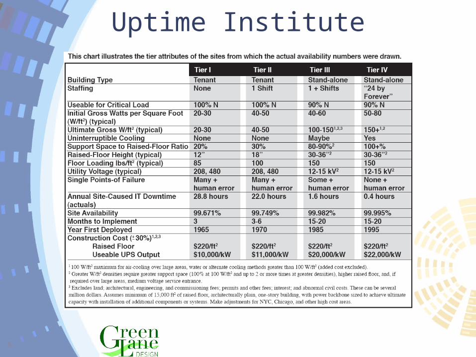
Uptime Institute

Typical Data Center Power
Utility Power
HVACPanel
AutomaticTransferSwitch
UPS
GeneratorPower
CRACUnits
Dist.Panel
PDU’s
Dist.
Data CenterServers
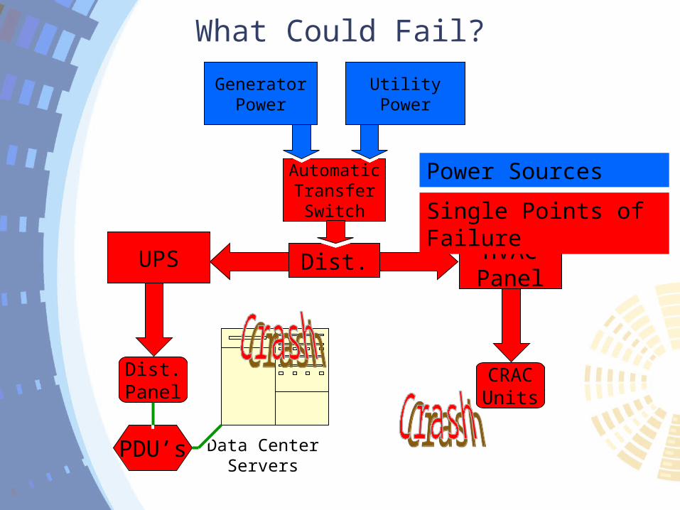
What Could Fail?
UtilityPower
HVACPanelHVACPanel
AutomaticTransferSwitch
AutomaticTransferSwitch
UPSUPS
GeneratorPower
CRACUnits
CRACUnits
Dist.Panel
Dist.Panel
PDU’sPDU’s
Dist.Dist.
Data CenterServers
Power Sources
Single Points of Failure

Risk AvoidanceHow to Mitigate Risk:• Design to eliminate Single Points of Failure (SPOF).• Provide redundant electrical power paths from the
utility and emergency backup system down to each server wherever possible.
• Provide methods to allow Preventative Maintenance (PM) for every aspect of the electrical distribution system without causing or risking an outage to the IT equipment.
• Provide at least an N+1 HVAC system allowing for the loss or PM of any single Computer Room Air Conditioning (CRAC) unit without causing overheating of the Data Center.
• Create Standard Operating Procedures (SOP) to reduce access to the data center and to maintain operational data for all aspects of the data center equipment.
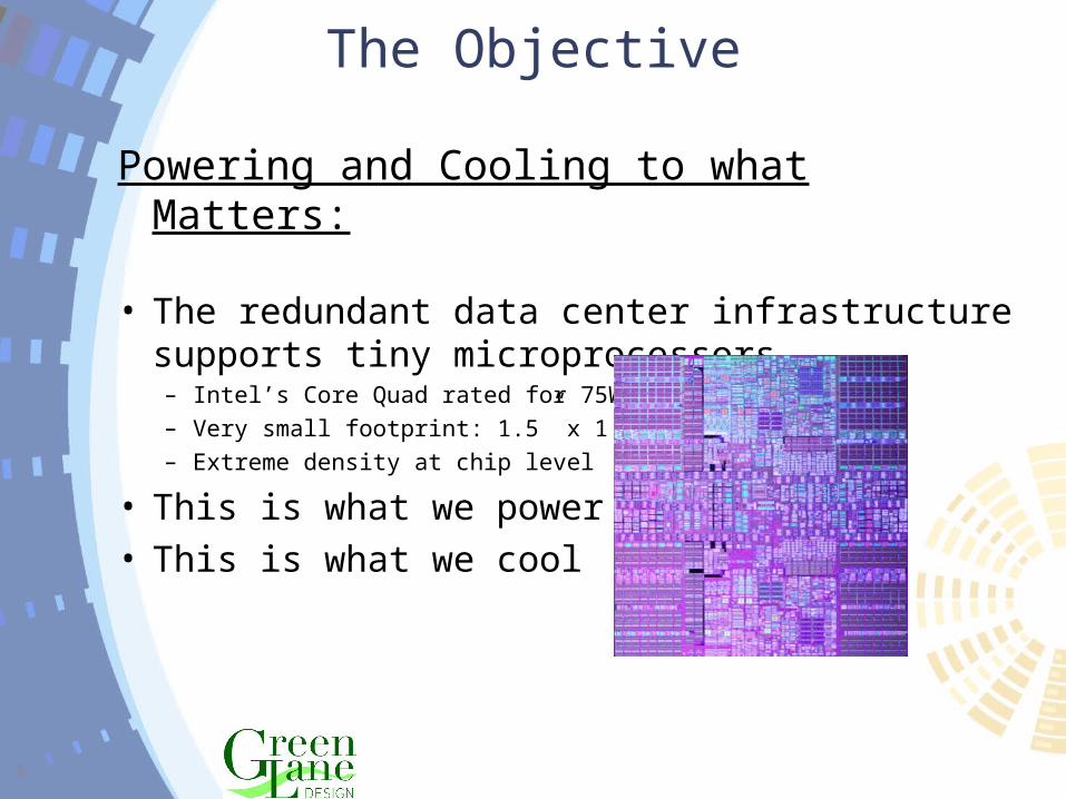
The Objective
Powering and Cooling to what Matters:
• The redundant data center infrastructure supports tiny microprocessors– Intel’s Core Quad rated for 75W– Very small footprint: 1.5” x 1.5”– Extreme density at chip level
• This is what we power• This is what we cool

Main Cooling System Components• Redundant Power Supply to Cooling
Equipmento No Single Point of Power Failure
• Redundant Heat Rejectiono Condensers, Cooling Towers or Dry
Coolers• Redundant Pumps
o Minimum N+1 Pumps• Redundant CRAC Units
o Recommended N+20% CRAC Units
Redundant Cooling Systems
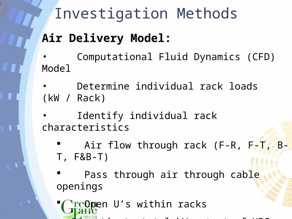
Investigation Methods
Air Delivery Model:
• Computational Fluid Dynamics (CFD) Model
• Determine individual rack loads (kW / Rack)
• Identify individual rack characteristics
Air flow through rack (F-R, F-T, B-T, F&B-T)
Pass through air through cable openings
Open U’s within racks
• Investigate total kW output of UPS equipment
• Identify cooling system components
Investigation Methods – Cont.
• Locate each CRAC unit and identify model and set points
• Locate each PDU and identify kVA and heat loss
• Locate the under floor (supply plenum) obstructions
Cable tray, conduit, piping, etc.
• Locate each floor diffuser and the percentage of opening
• Locate any obstructions within the room
• Investigate ceiling for use as return plenum
• Review findings with AIG to confirm input to model

The Supply Air Plenum
Plenum Air Velocity: The speed of the air as it leaves the CRAC units and reaches the floor diffusers.
Plenum Pressure: The static pressure produced by the CRAC unit air supply and the affect of the floor openings.
Supply Diffusers: Located in cold aisle to direct air to IT equipment / racks.
Pass Through Air: Any air passing through the floor not used to cool the IT equipment.
Provide Air to Entire Rack - Evenly• The supply plenum delivers air through the floor.• The air must have enough velocity to reach the
top server in the rack• Effect of pass through air from cable cutouts
– Decreases plenum pressure– Decreases air velocity through floor tiles
• More pass through air mean less air in the cold Aisle
• Air does not reach the equipment at the top of rack.
• Hot Aisle / Cold Aisle neutralized.

Temperature X Axis
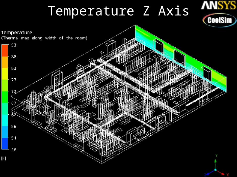
Temperature Z Axis
Thermal Cloud
The next slide show the air temperature ranges as a thermal cloud.
Thermal cloud: A volume of air that is all the same temperature.
Low Temp. Thermal Cloud: The first cloud represents the coldest area of the data center. This is the area where air is over delivered. It is also the best area to install new equipment.
Average Temp. Thermal Cloud: The second cloud represents the area of the data center that is 70 degrees F. This cloud should be in the hot aisles near the ceilings and in areas that do not require cooling.
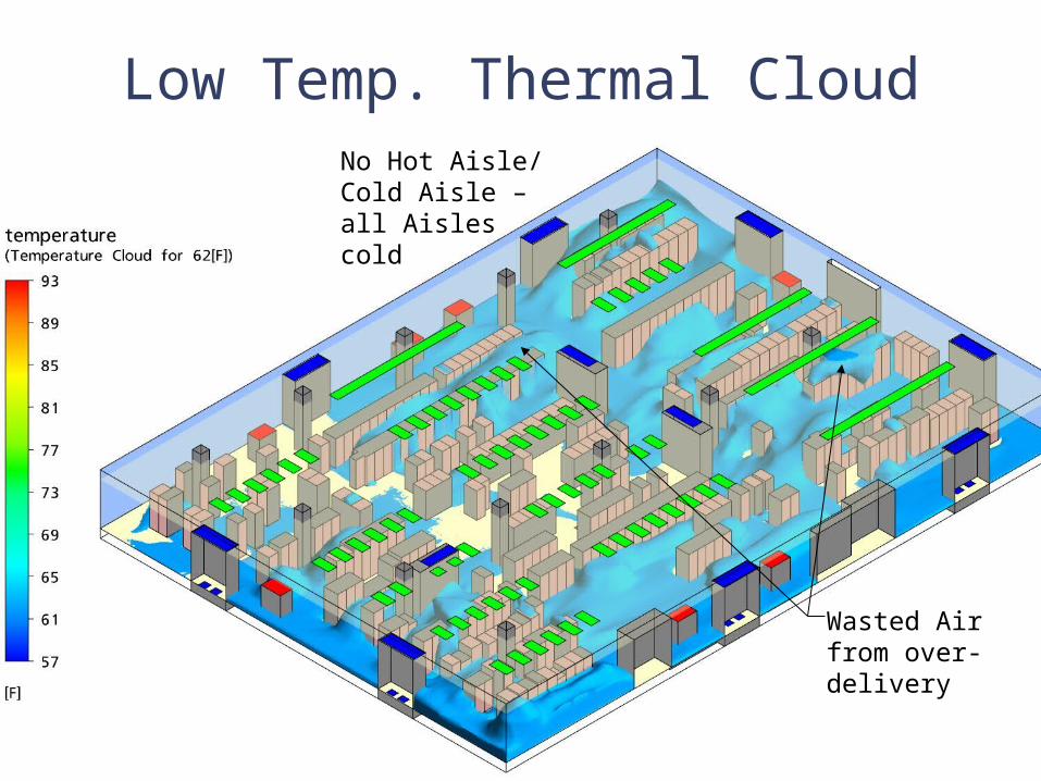
Low Temp. Thermal CloudNo Hot Aisle/ Cold Aisle – all Aisles cold
Wasted Air from over-delivery

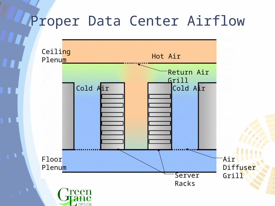
Proper Data Center Airflow
Server Racks
Air Diffuser Grill
Floor Plenum
Ceiling PlenumHot Air
Cold Air
Return Air Grill
Cold Air

Cable Cutouts in Raised Floor
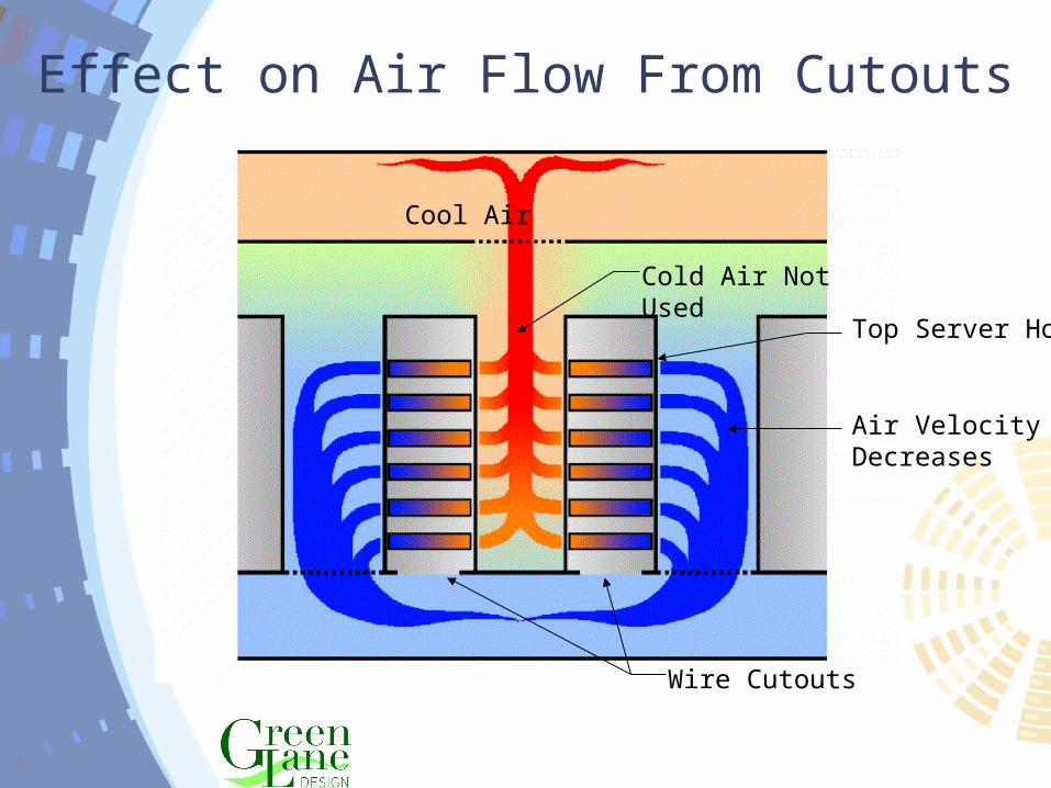
Effect on Air Flow From Cutouts
Wire Cutouts
Cool Air
Air VelocityDecreases
Cold Air Not Used
Top Server Hot
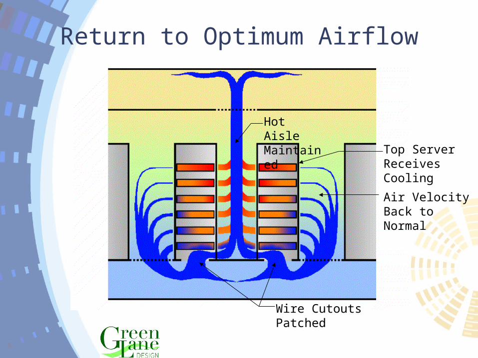
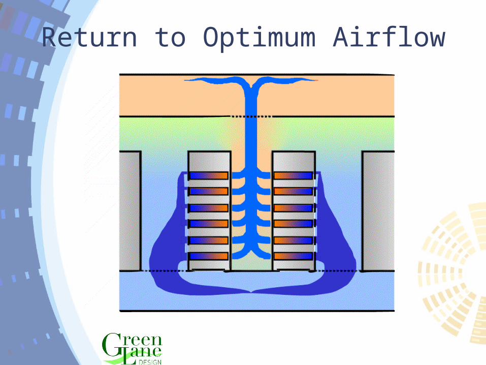
Return to Optimum Airflow
Wire Cutouts Patched
Hot Aisle Maintained
Top Server Receives Cooling
Air VelocityBack to Normal
Proper Data Center Airflow
Server Racks
Air Diffuser Grill
Floor Plenum
Ceiling PlenumHot Air
Cold Air
Return Air Grill
Cold Air

Effects of Open U’s in Rack
Floor Plenum
Ceiling PlenumWarm Air
Cold Air
Air VelocityDecreases
Top Server Hot
Cold Air Not Used
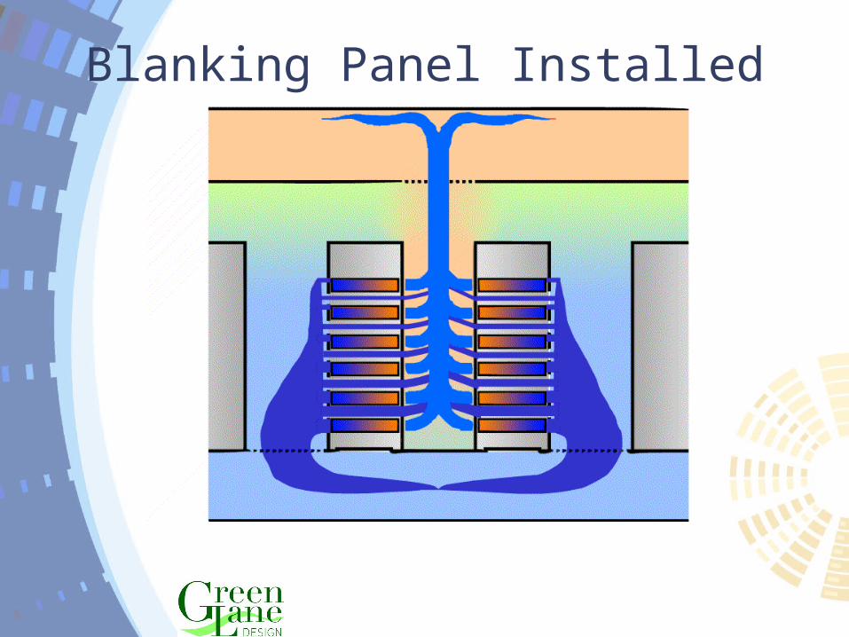
Blanking Panel Installed
Return to Optimum Airflow
Opportunities for Optimization• Establish Cold Aisle/Hot Aisle best practices • Eliminate Pass Through Air from cable cut outs• Provide blanking panels for unused U’s in Rack• Reduce air disruption in supply plenum – remove
unused wiring from under floor• Increases static pressure under the raised floor and
improves cool air delivery through perforated tiles• Determine required CFM requirements for each
rack• Provide proper air flow to racks• Position floor diffusers for proper airflow• Tune the air supply to the air requirements