2000 SERIES Electronic SPEEDBRAKE - INSTALLATION MANUAL · 2000 Series SPEEDBRAKETM – ELECTRICAL...
53
FAA Approval Date: Page 1 of 53 Installation Report Number: 08095 Document Number: 573SMAN0001 Revision Number: C Aircraft Serial Number: STC Number: SA00520NM PRECISE FLIGHT, INC. 63354 POWELL BUTTE ROAD BEND, OR 97701 800- 547-2558 www.preciseflight.com 2000 SERIES Electronic SPEEDBRAKE™ - INSTALLATION MANUAL Make: Piper Models: PA-46-301P Malibu PA-46-350P Malibu Mirage PA-46R-350T Malibu Matrix NOTICE The Airworthiness Limitations section (Section 4.0) is FAA Approved and Specifies maintenance required under Sections 43.16 and 91.403 of the Federal Aviation Regulations unless an alternative program has been FAA Approved. These Documents must be Kept with the Aircraft Records NOTE: READ THESE DIRECTIONS BEFORE STARTING! CHECK FOR EQUIPMENT THAT MAY INTERFERE WITH INSTALLATION BEFORE PROCEEDING! ALL WORK MUST BE DONE IN CONJUNCTION WITH APPLICABLE AIRCRAFT MAINTENANCE MANUAL! THIS DOCUMENT CONTAINS PROPRIETARY INFORMATION ON THE PRECISE FLIGHT, INC. (PFI) COMPANY AND ITS RECEIPT OR POSSESSION DOES NOT CONVEY ANY RIGHTS TO REPRODUCE, DISCLOSE ITS CONTENTS, OR TO MANUFACTURE, USE, OR SELL ANYTHING IT MAY DESCRIBE. REPRODUCTION, DISCLOSURE, OR USE WITHOUT SPECIFIC WRITTEN AUTHORIZATION OF PFI IS STRICTLY FORBIDDEN.
Transcript of 2000 SERIES Electronic SPEEDBRAKE - INSTALLATION MANUAL · 2000 Series SPEEDBRAKETM – ELECTRICAL...

FAA Approval Date: Page 1 of 53
Installation Report Number: 08095
Document Number: 573SMAN0001
Revision Number: C
Aircraft Serial Number:
STC Number: SA00520NM
PRECISE FLIGHT, INC.
63354 POWELL BUTTE ROAD
BEND, OR 97701
800- 547-2558
www.preciseflight.com
2000 SERIES Electronic SPEEDBRAKE™ - INSTALLATION MANUAL
Make: Piper
Models: PA-46-301P Malibu
PA-46-350P Malibu Mirage
PA-46R-350T Malibu Matrix
NOTICE The Airworthiness Limitations section (Section 4.0) is FAA Approved and Specifies
maintenance required under Sections 43.16 and 91.403 of the Federal Aviation Regulations unless an alternative program has been FAA Approved.
These Documents must be Kept with the Aircraft Records
NOTE: READ THESE DIRECTIONS BEFORE STARTING!
CHECK FOR EQUIPMENT THAT MAY INTERFERE WITH INSTALLATION
BEFORE PROCEEDING!
ALL WORK MUST BE DONE IN CONJUNCTION WITH APPLICABLE AIRCRAFT
MAINTENANCE MANUAL!
THIS DOCUMENT CONTAINS PROPRIETARY INFORMATION ON THE PRECISE FLIGHT, INC. (PFI) COMPANY AND ITS RECEIPT OR POSSESSION DOES NOT CONVEY ANY RIGHTS TO REPRODUCE, DISCLOSE ITS CONTENTS, OR TO MANUFACTURE, USE, OR SELL ANYTHING IT MAY DESCRIBE. REPRODUCTION, DISCLOSURE, OR USE WITHOUT SPECIFIC WRITTEN AUTHORIZATION OF PFI IS STRICTLY FORBIDDEN.

PRECISE FLIGHT, INC.
63354 POWELL BUTTE
ROAD
BEND, OR 97701
800- 547-2558
Installation Report: 08095
Document Number: 573SMAN0001
Revision Number: C
STC #: SA00520SE
2000 Series SPEEDBRAKETM – ELECTRICAL INSTALLATION MANUAL
TITLE PAGE RIGHTS APPLY
FAA Approval Date: Page 2 of 53
REVISIONS HISTORY
Rev. Description of Changes Author Date Approved
By
Approved
Date
IR Original Release DJC 1/29/03 JNS 2/17/03
A Updated Instructions for Continued Airworthiness, changed document number to new numbering system.
JNS 5/1/03 JNS 5/1/03
B Added PA-46R-350T Malibu Matrix non-pressurized aircraft.
JNS 1/8/08 JNS 1/8/08
C Updated the document format throughout full document; Added warranty web address to section 1.1, item 13; Fixed various misspellings and typos throughout document, Section 2.9: Added new Section 1.2; Added new Section 1.3; Added new Section 1.7 Updated Section 2.10 to reflect new ALC part number 010S0303-1; Updated Figure 12, item D to state (EMI/RFI); Added new Section 5.0 (References); Updated Section 6.0 (old section 5.0) with removing parts list and installation instruction drawings and adding electrical loads analysis form. Revised old PFI numbers to current with prefixes, changed clinch nuts used on lower doublers to nut plates.
W. Ashforth R. Norris
9/26/2011 TBD --/--/----

PRECISE FLIGHT, INC.
63354 POWELL BUTTE
ROAD
BEND, OR 97701
800- 547-2558
Installation Report: 08095
Document Number: 573SMAN0001
Revision Number: C
STC #: SA00520SE
2000 Series SPEEDBRAKETM – ELECTRICAL INSTALLATION MANUAL
TITLE PAGE RIGHTS APPLY
FAA Approval Date: Page 3 of 53
LIST OF ACTIVE PAGES
Original Added Pages Original Added Pages
PAGE REV PAGE REV PAGE REV PAGE REV
1 C 36 C 2 C 37 C 3 C 38 C 4 C 39 C 5 C 40 C 6 C 41 C 7 C 42 C 8 C 43 C 9 C 44 C
10 C 45 C 11 C 46 C 12 C 47 C 13 C 48 C 14 C 49 C 15 C 50 C 16 C 51 C 17 C 52 C 18 C 53 C 19 C 20 C 21 C 22 C 23 C 24 C 25 C 26 C 27 C 28 C 29 C 30 C 31 C 32 C 33 C 34 C 35 C
PRECISE FLIGHT, INC.
63354 POWELL BUTTE
ROAD
BEND, OR 97701
800- 547-2558
Installation Report: 08095
Document Number: 573SMAN0001
Revision Number: C
STC #: SA00520SE
2000 Series SPEEDBRAKETM – ELECTRICAL INSTALLATION MANUAL
TITLE PAGE RIGHTS APPLY
FAA Approval Date: Page 4 of 53
TABLE OF CONTENTS
REVISIONS HISTORY ......................................................................................................... 2
LIST OF ACTIVE PAGES ..................................................................................................... 3
TABLE OF CONTENTS ....................................................................................................... 4
LIST OF TABLES ................................................................................................................. 5
LIST OF FIGURES ............................................................................................................... 5
1.0 OVERVIEW .................................................................................................................... 7
1.1 INSTALLATION OVERVIEW ................................................................................................... 7
1.2 HOW TO USE THIS MANUAL AND READ THE DRAWINGS ........................................................ 8
1.2.1 Notes and Warnings ................................................................................................. 8
1.2.2 Drawing Interpretation .............................................................................................. 8 1.2.2.1 Parts Lists ......................................................................................................................................................... 9
1.3 IMPORTANT INSTALLATION NOTES ..................................................................................... 10
1.4 LIST OF TOOLS REQUIRED ................................................................................................ 10
1.5 LIST OF SUPPLIES REQUIRED............................................................................................ 11
1.6 LIST OF ABBREVIATIONS ................................................................................................... 11
1.7 MANUAL AND ICA REVISIONS ........................................................................................... 12
2.0 INSTALLATION INSTRUCTIONS ................................................................................ 13
2.1 REMOVING EXISTING LOWER WING INSPECTION PANEL AND DOUBLER ................................ 13
2.2 LOCATING NEW LOWER WING INSPECTION PANEL & DOUBLER .......................................... 15
2.3 LOCATING LOWER WING ACCESS COVER CUTOUT ............................................................ 17
2.4 LOCATING UPPER WING CUTOUT ..................................................................................... 19
2.5 SPEEDBRAKETM
CARTRIDGE INSTALLATION (TEMPORARY) ................................................. 23
2.6 UPPER DOUBLER BONDING ............................................................................................. 27
2.7 LOWER DOUBLER BONDING ............................................................................................. 29
2.8 PITOT TUBE INSTALLATION W/NEW ACCESS COVER PANEL ............................................... 32
2.9 EXTERIOR PANEL AND INTERIOR REMOVAL ........................................................................ 33
2.10 INSTALLING THE ASYMMETRIC LOGIC CONTROL (ALC) ..................................................... 34
2.11 FEED-THROUGH DOUBLER AND BULKHEAD FITTING INSTALLATION ...................................... 35
2.12 WIRING THE SPEEDBRAKE™ CARTRIDGES TO THE ALC ................................................. 37
2.13 WIRING THE ASYMMETRIC LOGIC CONTROL (ALC) .......................................................... 40
2.14 CIRCUIT BREAKER AND SWITCH ..................................................................................... 41
2.15 SPEEDBRAKE™ CARTRIDGE INSTALLATION (PERMANENT) ............................................... 42
2.16 PLACARDS INSTALLATION .............................................................................................. 44

PRECISE FLIGHT, INC.
63354 POWELL BUTTE
ROAD
BEND, OR 97701
800- 547-2558
Installation Report: 08095
Document Number: 573SMAN0001
Revision Number: C
STC #: SA00520SE
2000 Series SPEEDBRAKETM – ELECTRICAL INSTALLATION MANUAL
TITLE PAGE RIGHTS APPLY
FAA Approval Date: Page 5 of 53
2.17 SPEEDBRAKE OPERATIONAL TEST .................................................................................. 45
2.18 DOCUMENTATION .......................................................................................................... 46
3.0 TROUBLE SHOOTING GUIDE .................................................................................... 48
3.1 SPEEDBRAKE CARTRIDGE FAILS TO OPERATE CORRECTLY ............................................... 48
3.2 WARNINGS ..................................................................................................................... 48
3.3 FOR ADDITIONAL TECHNICAL ASSISTANCE ........................................................................ 48
4.0 INSTRUCTIONS FOR CONTINUED AIRWORTHINESS ............................................. 49
4.1 INTRODUCTION ................................................................................................................ 49
4.2 SYSTEM DESCRIPTION ..................................................................................................... 49
4.3 SPECIAL TOOLS REQUIRED .............................................................................................. 50
4.4 MAINTENANCE INSTRUCTIONS ........................................................................................... 50
4.5 TROUBLE SHOOTING GUIDE.............................................................................................. 50
4.6 AIRWORTHINESS LIMITATIONS ........................................................................................... 50
4.7 SCHEDULED MAINTENANCE INTERVALS AND INSPECTIONS FOR CONTINUED AIRWORTHINESS 50
5.0 REFERENCES ............................................................................................................. 52
6.0 APPENDICES ............................................................................................................... 53
6.1 ELECTRICAL LOADS ANALYSIS FORM: ................................................................................ 53
LIST OF TABLES
Table 1 - Tools Required .................................................................................................... 10
Table 2 – Supplies Required .............................................................................................. 11
Table 3 – List of Abbreviations ........................................................................................... 11
Table 4 - Scheduled Maintenance Intervals and Inspections ............................................. 51
LIST OF FIGURES
Figure 1 - Third Angle Projection .......................................................................................... 8
Figure 2 - Sample Parts List from Drawing 573S0001 .......................................................... 9
Figure 3 –Lower Wing Template ......................................................................................... 16
Figure 4 – Upper Doubler Placement (Left Shown) ............................................................ 20
Figure 5 – Upper Wing Cutout ............................................................................................ 21
Figure 6 – Finished Upper Wing Skin Cutout...................................................................... 22
Figure 7 – Temporary SpeedBrake Installation (Inboard Left Shown) ................................ 25
Figure 8 – Bonded Lower Doubler (Right Shown) .............................................................. 31

PRECISE FLIGHT, INC.
63354 POWELL BUTTE
ROAD
BEND, OR 97701
800- 547-2558
Installation Report: 08095
Document Number: 573SMAN0001
Revision Number: C
STC #: SA00520SE
2000 Series SPEEDBRAKETM – ELECTRICAL INSTALLATION MANUAL
TITLE PAGE RIGHTS APPLY
FAA Approval Date: Page 6 of 53
Figure 9 – Floor Panel ........................................................................................................ 34
Figure 10 – Feed-Through Doubler Installation (Left Shown) ............................................. 36
Figure 11 – Connector Pinouts (Reference Only) ............................................................... 39
Figure 12 - Suggested FAA Form 337 Description of Work Statement .............................. 47
Figure 13 – SpeedBrake Annunciator Switch ..................................................................... 49

PRECISE FLIGHT, INC.
63354 POWELL BUTTE
ROAD
BEND, OR 97701
800- 547-2558
Installation Report: 08095
Document Number: 573SMAN0001
Revision Number: C
STC #: SA00520SE
2000 Series SPEEDBRAKETM – ELECTRICAL INSTALLATION MANUAL
TITLE PAGE RIGHTS APPLY
FAA Approval Date: Page 7 of 53
1.0 OVERVIEW
1.1 INSTALLATION OVERVIEW
The installation of Precise Flight, Inc. SpeedBrakes™ consists of the following:
1. Debonding of existing inspection panel doubler in the bottom of each wing skin at WS 100.25.
2. Enlarging oval openings in the bottom of each wing skin using locating templates.
3. Cutting rectangular holes in the top wing skins using the templates and new doubler as guides.
4. Installing / bonding new doublers to reinforce the new cutout in the upper wing skins.
5. Installing the SpeedBrake cartridges and side support brackets.
6. Installing / bonding new lower wing skin doublers to reinforce the enlarged areas.
7. Installing / bonding doublers and bulkhead fittings in each wing root through the pressure vessel.
8. Wiring the SpeedBrakes™ will require removing pilot and co-pilot side panels, front seats, and wing and wing spar inspection panels. Wires will then be run through the wing and fuselage to a centrally located control unit.
9. Installing a circuit breaker to protect the system, a switch to actuate the system, and an Annunciator to indicate system function.
10. Functionally testing the SpeedBrake™ system.
11. Reinstalling all removed panels, interior, and touch-up painting if required.
12. Filling out necessary FAA paperwork to return the aircraft to service.
13. Completing warranty information at http://preciseflight.com/support/warranty and submitting to PFI.
Each section will include a list of tools and parts required.

PRECISE FLIGHT, INC.
63354 POWELL BUTTE
ROAD
BEND, OR 97701
800- 547-2558
Installation Report: 08095
Document Number: 573SMAN0001
Revision Number: C
STC #: SA00520SE
2000 Series SPEEDBRAKETM – ELECTRICAL INSTALLATION MANUAL
TITLE PAGE RIGHTS APPLY
FAA Approval Date: Page 8 of 53
1.2 HOW TO USE THIS MANUAL AND READ THE DRAWINGS
1.2.1 Notes and Warnings
Because of the uniqueness of this installation in existing aircraft, Precise Flight has added notes, cautions, and warnings to the installation manual.
NOTE Notes are used to emphasize certain steps to prevent problems with the installation. We, at Precise Flight, have added these notes to prevent problems before they occur based on our experience installing these
systems, or from ‘your’ feedback.
! CAUTION ! Cautions are used if aircraft damage can occur due to a missed step.
Please remember, we only have these in key locations based on previous experience. It is the installer’s responsibility to make sure the
installation is done correctly, and to airworthiness standards.
!! WARNING !! Warnings are used to emphasize a part of the installation where if done
incorrectly can pose a serious hazard to the installer or the pilot.
1.2.2 Drawing Interpretation
All drawings produced by Precise Flight Inc, are based on ASME Y14.5-1994 standards, measurements in Inches, and Third Angle Projection. Information on the drawings including notes, parts, etc. are part of the FAA approved design and in most cases do include important installation and manufacturing information.
Third Angle Projection is the method drawing views are produced as shown in Figure 1.
Figure 1 - Third Angle Projection (Earle, James. “Engineering Design Graphics”)

PRECISE FLIGHT, INC.
63354 POWELL BUTTE
ROAD
BEND, OR 97701
800- 547-2558
Installation Report: 08095
Document Number: 573SMAN0001
Revision Number: C
STC #: SA00520SE
2000 Series SPEEDBRAKETM – ELECTRICAL INSTALLATION MANUAL
TITLE PAGE RIGHTS APPLY
FAA Approval Date: Page 9 of 53
1.2.2.1 Parts Lists
A source of possible confusion when reading drawings is the proper interpretation of the parts list. This STC includes multiple aircraft models, and voltages, in the same drawing package. Because of the difference between the Piper Malibu PA-46-301P, PA-46-350P (Mirage) and PA-46R-350T (Matrix) aircraft installations, special care must be taken to make sure the correct installation is used.
Figure 2 below shows a SpeedBrake installation, and which drawings are applicable.
Figure 2 - Sample Parts List from Drawing 573S0001
This chart shows part number 573S0001-1. Because all models listed on the STC are applicable, this installation would be used for any electrical system as described in section 2.0 of this document, or on the STC certificate. From here, the installer moves to the left until a “\” marks that applicable installation. Follow the column up to see what quantity is greater than 0. Then follow the chart back to the right to find the drawing/part number for the applicable installation. Drawings are shown in this example, but parts work on the same principle on the other installation drawings.
PRECISE FLIGHT, INC.
63354 POWELL BUTTE
ROAD
BEND, OR 97701
800- 547-2558
Installation Report: 08095
Document Number: 573SMAN0001
Revision Number: C
STC #: SA00520SE
2000 Series SPEEDBRAKETM – ELECTRICAL INSTALLATION MANUAL
TITLE PAGE RIGHTS APPLY
FAA Approval Date: Page 10 of 53
1.3 IMPORTANT INSTALLATION NOTES
This section lists specific installation notes of importance for this STC installation.
NOTE It is the installer’s responsibility to verify that the installation of the
SpeedBrake™ 2000 system will not interfere with any existing modification on the aircraft prior to starting the installation. Contact
Precise Flight if there appears to be an installation conflict.
! CAUTION ! Verify aircraft voltage and SpeedBrake kit voltage prior to installation. Failure to use correct installation kit may damage aircraft systems, or
SpeedBrake installation.
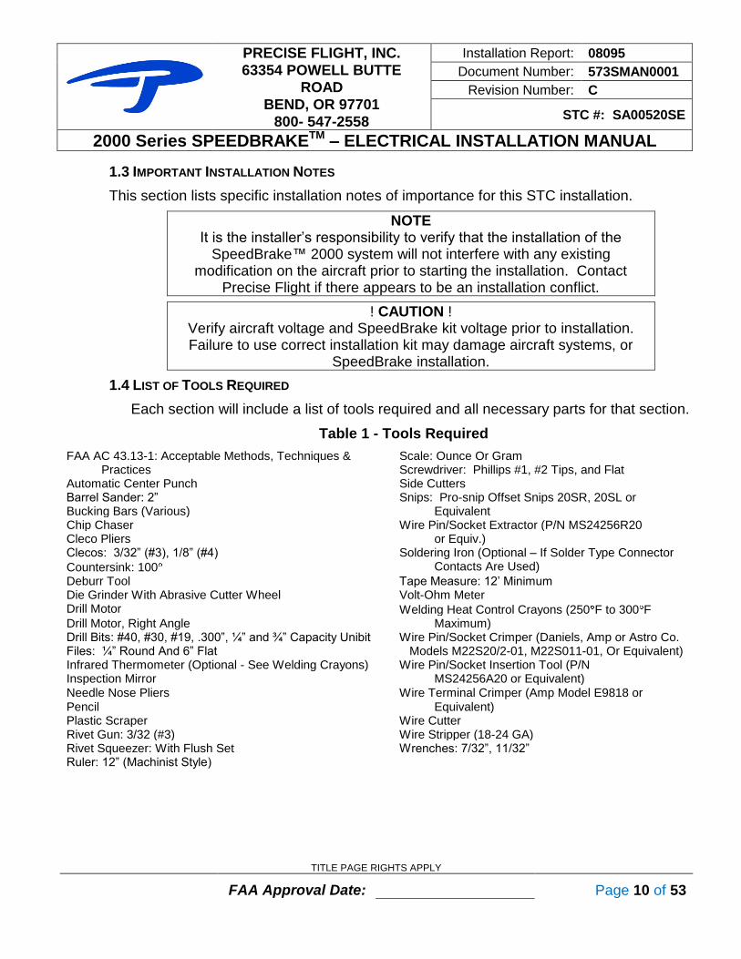
1.4 LIST OF TOOLS REQUIRED
Each section will include a list of tools required and all necessary parts for that section.
Table 1 - Tools Required
FAA AC 43.13-1: Acceptable Methods, Techniques & Scale: Ounce Or Gram Practices Screwdriver: Phillips #1, #2 Tips, and Flat Automatic Center Punch Side Cutters Barrel Sander: 2” Snips: Pro-snip Offset Snips 20SR, 20SL or Bucking Bars (Various) Equivalent Chip Chaser Wire Pin/Socket Extractor (P/N MS24256R20 Cleco Pliers or Equiv.) Clecos: 3/32” (#3), 1/8” (#4) Soldering Iron (Optional – If Solder Type Connector
Countersink: 100 Contacts Are Used)
Deburr Tool Tape Measure: 12’ Minimum Die Grinder With Abrasive Cutter Wheel Volt-Ohm Meter Drill Motor Welding Heat Control Crayons (250 F to 300 F Drill Motor, Right Angle Maximum) Drill Bits: #40, #30, #19, .300”, ¼” and ¾” Capacity Unibit Wire Pin/Socket Crimper (Daniels, Amp or Astro Co. Files: ¼” Round And 6” Flat Models M22S20/2-01, M22S011-01, Or Equivalent) Infrared Thermometer (Optional - See Welding Crayons) Wire Pin/Socket Insertion Tool (P/N Inspection Mirror MS24256A20 or Equivalent) Needle Nose Pliers Wire Terminal Crimper (Amp Model E9818 or Pencil Equivalent) Plastic Scraper Wire Cutter Rivet Gun: 3/32 (#3) Wire Stripper (18-24 GA) Rivet Squeezer: With Flush Set Wrenches: 7/32”, 11/32” Ruler: 12” (Machinist Style)

PRECISE FLIGHT, INC.
63354 POWELL BUTTE
ROAD
BEND, OR 97701
800- 547-2558
Installation Report: 08095
Document Number: 573SMAN0001
Revision Number: C
STC #: SA00520SE
2000 Series SPEEDBRAKETM – ELECTRICAL INSTALLATION MANUAL
TITLE PAGE RIGHTS APPLY
FAA Approval Date: Page 11 of 53
1.5 LIST OF SUPPLIES REQUIRED
Table 2 – Supplies Required
Alodine Alumaprep Bon Ami cleaner Carbon paper: 8.5”x11” Distilled Water Double back tape, 3M or similar Felt marker: Ultra fine point Hysol EA9309.3NA Adhesive
Isopropyl alcohol Masking tape: ¾” ProSeal: A1/2 or B1/2 Sandpaper: various grits Solder: Rosin Core (Optional) Wax (Bee's wax or equivalent) Wax paper Zinc Chromate
1.6 LIST OF ABBREVIATIONS
This section is to provide the reader with a complete state of the abbreviations used in this document and installation.
Table 3 – List of Abbreviations
A/R As Required
AC Advisory Circular AMM Airplane Maintenance Manual BL Butt Line CB Circuit Breaker DC Direct Current FAA Federal Aviation Administration FS Fuselage Station (Flight Station) In Inch IR Initial Release Lb, lbs Pounds PFI Precise Flight, Inc. N/A or ‘-‘ Not Applicable V Volts VDC Volts Direct Current WL Water Line WS Wing Station

PRECISE FLIGHT, INC.
63354 POWELL BUTTE
ROAD
BEND, OR 97701
800- 547-2558
Installation Report: 08095
Document Number: 573SMAN0001
Revision Number: C
STC #: SA00520SE
2000 Series SPEEDBRAKETM – ELECTRICAL INSTALLATION MANUAL
TITLE PAGE RIGHTS APPLY
FAA Approval Date: Page 12 of 53
1.7 MANUAL AND ICA REVISIONS
To ensure the maintenance of our existing aircraft fleet, possible revisions to this manual and especially section 4.0 Instructions for Continued Airworthiness may require updating over the life of the aircraft. Per the applicable Federal Aviation Regulations, an update process is required to properly maintain these instructions, in addition to the aircraft itself. Because of this, it is imperative to complete the online registration for the aircraft once the system is installed. Revisions can be made by a service letter from Precise Flight, an Airworthiness Directive as issued by the administrator, by single page updates, or a complete replacement of all pages of the manual. It must be clearly noted as to the revision level of the pages listed in The List of Active Pages. If a single sheet(s) is replaced, replace the list of active pages with the new one provided, or update the list manually and initial and date the list.

PRECISE FLIGHT, INC.
63354 POWELL BUTTE
ROAD
BEND, OR 97701
800- 547-2558
Installation Report: 08095
Document Number: 573SMAN0001
Revision Number: C
STC #: SA00520SE
2000 Series SPEEDBRAKETM – ELECTRICAL INSTALLATION MANUAL
TITLE PAGE RIGHTS APPLY
FAA Approval Date: Page 13 of 53
2.0 INSTALLATION INSTRUCTIONS
Read all installation instructions prior to starting the installation, or modifying the aircraft. If necessary, please contact Precise Flight Incorporated at (541) 382-8684 and ask for SpeedBrake assistance, visit our website WWW.PreciseFlight.com, or write us at the address above, if you have any questions.
! CAUTION ! Verify aircraft voltage and SpeedBrake kit voltage prior to installation. Failure to use correct installation kit may damage aircraft systems, or
SpeedBrake system.
2.1 REMOVING EXISTING LOWER WING INSPECTION PANEL AND DOUBLER
TOOLS REQUIRED
Heat Gun Isopropyl alcohol Infra-Red Thermometer (Opt.)
Plastic Scraper Sandpaper Welding Heat Crayons
PARTS REQUIRED
Part Number Qty Description PFI Number
573S0006-1 1 Lower LH Wing Template -
573S0006-2 1 Lower RH Wing Template -
!! WARNING !! Use extreme care when de-bonding the doubler as excessive heat can
debond stringers next to the doubler!!
RIGHT WING
1. Referencing Template Drawing 573S0006, remove the right wing inspection panel located at WS 100.25. Using the welding heat crayons draw a thick line, inside and outside the wing, around the doubler outside edge. Be sure to draw the line inside of the stringer edges.
2. Using a heat gun, carefully heat the inboard-inside edge of the doubler while applying force on and between the doubler and wing skin.
NOTE If available, use an infrared thermometer to ensure the local temperature
of the wing skin and doubler does not exceed 300 F.
PRECISE FLIGHT, INC.
63354 POWELL BUTTE
ROAD
BEND, OR 97701
800- 547-2558
Installation Report: 08095
Document Number: 573SMAN0001
Revision Number: C
STC #: SA00520SE
2000 Series SPEEDBRAKETM – ELECTRICAL INSTALLATION MANUAL
TITLE PAGE RIGHTS APPLY
FAA Approval Date: Page 14 of 53
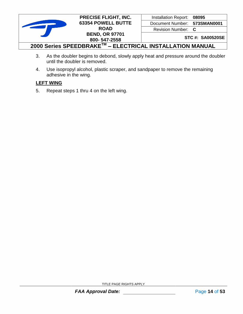
3. As the doubler begins to debond, slowly apply heat and pressure around the doubler until the doubler is removed.
4. Use isopropyl alcohol, plastic scraper, and sandpaper to remove the remaining adhesive in the wing.
LEFT WING
5. Repeat steps 1 thru 4 on the left wing.
PRECISE FLIGHT, INC.
63354 POWELL BUTTE
ROAD
BEND, OR 97701
800- 547-2558
Installation Report: 08095
Document Number: 573SMAN0001
Revision Number: C
STC #: SA00520SE
2000 Series SPEEDBRAKETM – ELECTRICAL INSTALLATION MANUAL
TITLE PAGE RIGHTS APPLY
FAA Approval Date: Page 15 of 53
2.2 LOCATING NEW LOWER WING INSPECTION PANEL & DOUBLER
TOOLS REQUIRED
Automatic Center Punch Carbon Paper Masking Tape
Pencil Tape Measure -
PARTS REQUIRED
Part Number Qty Description PFI Number
573S0006-1 1 Lower LH Wing Template -
573S0006-2 1 Lower RH Wing Template -
573S0010-2 1* Access Cover, Right -
573S0010-3 1* Access Cover, Left -
573S0020-1 1* Alternate Access Cover, Left -
573S0020-2 1* Alternate Access Cover, Right - * See Packing List
RIGHT WING
1. Using Template 573S0006-2, check alignment of template by placing the template on lower right aircraft wing between WS 93.00 and WS 107.50. Adjust Template so that the rows of rivets marked “CRITICAL RIVET LINES” are aligned with the corresponding wing rivets. Once aligned, place a piece of carbon paper between the wing and template, and secure the template to the wing skin using masking tape.
NOTE Use a pencil to highlight the rivet locations on the template. Adjust template so
template rivet lines match the existing rivet lines exactly. Actual rivet locations
do not need to match ”+”marks on template .
2. Place the Right Access Cover (P/N 573S0010-2 or 573S0020-2) on the template and align the screw holes with the template. Using a pencil, trace around the access cover to transfer its location (carbon paper) to the lower wing skin. Remove the template and set aside.
LEFT WING
3. Repeat steps 1 thru 2 on the left wing using Template 573S0006-1 and Left Access Cover (P/N 573S0010-3 or 573S0020-1).

PRECISE FLIGHT, INC.
63354 POWELL BUTTE
ROAD
BEND, OR 97701
800- 547-2558
Installation Report: 08095
Document Number: 573SMAN0001
Revision Number: C
STC #: SA00520SE
2000 Series SPEEDBRAKETM – ELECTRICAL INSTALLATION MANUAL
TITLE PAGE RIGHTS APPLY
FAA Approval Date: Page 16 of 53
Figure 3 –Lower Wing Template

PRECISE FLIGHT, INC.
63354 POWELL BUTTE
ROAD
BEND, OR 97701
800- 547-2558
Installation Report: 08095
Document Number: 573SMAN0001
Revision Number: C
STC #: SA00520SE
2000 Series SPEEDBRAKETM – ELECTRICAL INSTALLATION MANUAL
TITLE PAGE RIGHTS APPLY
FAA Approval Date: Page 17 of 53
2.3 LOCATING LOWER WING ACCESS COVER CUTOUT
TOOLS REQUIRED
Deburr Tool Drum Sander: 2” Fine Point Felt Marker
Drill: .300" Files: ¼” Round & 6” Flat Snips: 20SR, 20SL
PARTS REQUIRED
Part Number Qty Description PFI Number
573S0010-1 1 Lower Doubler -
573S0010-2 1* Access Cover, Right -
573S0010-3 1* Access Cover, Left -
573S0020-1 1* Alternate Access Cover, Left -
573S0020-2 1* Alternate Access Cover, Right -
MS24694S5 2 Screw, 8-32 x 1/2 FLH MS 01477 * See Packing List
Various methods may be employed to make the cutouts in the wings.
!! WARNING !! Use extreme care.
It has been proven helpful to do the following:
RIGHT WING
1. Mask off the wing around the area to be cut.
2. Using a die grinder, abrasive cutters, or snips, enlarge the oval hole to the inside of the traced line.
3. After Alodining, install 2 Nutplates (P/N MS 07067) into the Lower Wing Skin Doubler using per notes on drawing 573S0010.
4. Place the lower wing skin doubler (P/N 5730010-1) inside the wing, (Note: verify orientation of right side doubler as per drawing 573S0006-2) center over the access cover cutout, and verify it does not overlap the stringer edges. Adjust as necessary inside the wing.
5. Place the access cover in the cutout and align with the lower doubler and nutplates. Check the cutout for proper alignment with the access cover. Two 8-32 Screws (P/N MS 01477) may be used to hold the access cover in place. Re-mark the cutout as necessary.
6. Remove the lower doubler and access cover and finish the cutout using a drum sander, round and flat files. Use the right access cover (P/N 573S0010-2 or 573S0020-2) to check cutout size.
PRECISE FLIGHT, INC.
63354 POWELL BUTTE
ROAD
BEND, OR 97701
800- 547-2558
Installation Report: 08095
Document Number: 573SMAN0001
Revision Number: C
STC #: SA00520SE
2000 Series SPEEDBRAKETM – ELECTRICAL INSTALLATION MANUAL
TITLE PAGE RIGHTS APPLY
FAA Approval Date: Page 18 of 53
! CAUTION !
These cutouts will be the finished product. Care must be taken when finishing these openings.
7. Remove the lower doubler, mark it for the right wing, and set aside.
LEFT WING
8. Repeat steps 1 thru 7 on the left wing using left access cover (P/N 573S0010-3 or 573S0020-1). Note: verify orientation of left lower wing doubler per drawing 573S0006-1.

PRECISE FLIGHT, INC.
63354 POWELL BUTTE
ROAD
BEND, OR 97701
800- 547-2558
Installation Report: 08095
Document Number: 573SMAN0001
Revision Number: C
STC #: SA00520SE
2000 Series SPEEDBRAKETM – ELECTRICAL INSTALLATION MANUAL
TITLE PAGE RIGHTS APPLY
FAA Approval Date: Page 19 of 53
2.4 LOCATING UPPER WING CUTOUT
TOOLS REQUIRED
Cleco Pliers Clecos: 3/32”, 1/8” Countersink, 100
Deburring Tool Die Grinder with Abrasive Disc Double Stick Tape
Drill Motor Drill Bits: #40, #35, 1/4" Unibit Files: 1/4" Round, 6" Flat
Fine Point Felt Marker Masking Tape Machinist’s scale
PARTS REQUIRED
Part Number Qty Description PFI Number
573S0009-1 1* Left Upper Doubler -
573S0009-2 1* Right Upper Doubler -
573S0009-4 1* Left Upper Doubler, Reinforced -
573S0009-5 1* Right Upper Doubler, Reinforced -
573S0005-1 1 Left Upper Template -
573S0005-2 1 Right Upper Template -
010S0059-74 1 L SpeedBrake Cartridge -
010S0059-73 1 R SpeedBrake Cartridge -
MS24693C3 16 Screw, 4-40 x 5/16 FLH SS MS 07026 * See Packing List
NOTE The cutouts will be the finished product. Care must be taken when finishing these
openings.
RIGHT WING
1. On the underside of the right upper wing skin, use a machinist’s scale and fine point felt marker to measure a distance of 1" perpendicular from the inboard rib.
2. Using double stick tape, place the right upper wing skin doubler (P/N 573S0005-2 or 573S0005-5) on the bottom of the upper wing skin. Place the inboard edge of the doubler on the mark, exactly 1" from the inboard rib where previously marked. See Figure 4 – Upper Doubler Placement (Left Shown)

PRECISE FLIGHT, INC.
63354 POWELL BUTTE
ROAD
BEND, OR 97701
800- 547-2558
Installation Report: 08095
Document Number: 573SMAN0001
Revision Number: C
STC #: SA00520SE
2000 Series SPEEDBRAKETM – ELECTRICAL INSTALLATION MANUAL
TITLE PAGE RIGHTS APPLY
FAA Approval Date: Page 20 of 53
Figure 4 – Upper Doubler Placement (Left Shown)
3. Center the Doubler’s offset flanges between the forward and aft wing stringers. Use the double stick tape to hold the doubler in the proper position.
4. Using a #40 drill, drill two of the eight SpeedBrake mounting holes.
5. Remove the doubler and tape, and reinstall on the upper surface of the upper wing skin using 3/32” Clecos.
NOTE Be sure to align the doubler in the proper location, inboard edge inboard, and
flanges down
6. Drill the remaining 6 holes using a #40 drill. Cleco as you drill to ensure no movement.
7. Transfer the SpeedBrake opening to the upper wing skin using a fine tip felt marker.
8. Using a #40 drill, drill the four corners of the SpeedBrake opening 1/8" in from the corner. Use a Unibit to increase the hole size to the inside edge of the marked line.
9. Remove the Upper Doubler and mask off the wing around the area to be cut. See Figure 5 – Upper Wing Cutout.

PRECISE FLIGHT, INC.
63354 POWELL BUTTE
ROAD
BEND, OR 97701
800- 547-2558
Installation Report: 08095
Document Number: 573SMAN0001
Revision Number: C
STC #: SA00520SE
2000 Series SPEEDBRAKETM – ELECTRICAL INSTALLATION MANUAL
TITLE PAGE RIGHTS APPLY
FAA Approval Date: Page 21 of 53
Figure 5 – Upper Wing Cutout
10. Using a die grinder with an abrasive disc, or snips, cut a line between each of the four holes, remaining inside of the marked line.
11. Install and cleco the upper doubler to the bottom of the upper wing skin.
12. Using 1/4" round, and 6" flat files, file the opening to the doubler edges until they appear as one skin.
! CAUTION !
These cutouts will be the finished product. Care must be taken when finishing these openings.
13. Remove the Clecos one at a time and re-drill the 8 mounting holes using a #30 drill and re-cleco.
14. Use a 100 countersink to fit each of the screws holes. Remove the upper doubler and deburr all holes.
15. Install the right SpeedBrake (P/N 010S0059-73) and the upper doubler using 8 Stainless Steel Screws (P/N MS 07026).
16. Check for a .030" gap on all sides between the stainless SpeedBrake caps and the skin and doubler cutout. This will ensure proper SpeedBrake function and prevent binding. If needed open the cutout until a .030" gap exists on all sides.
17. Remove SpeedBrake and doubler and deburr doubler cutout. See Figure 6 – Finished Upper Wing Skin Cutout

PRECISE FLIGHT, INC.
63354 POWELL BUTTE
ROAD
BEND, OR 97701
800- 547-2558
Installation Report: 08095
Document Number: 573SMAN0001
Revision Number: C
STC #: SA00520SE
2000 Series SPEEDBRAKETM – ELECTRICAL INSTALLATION MANUAL
TITLE PAGE RIGHTS APPLY
FAA Approval Date: Page 22 of 53
Figure 6 – Finished Upper Wing Skin Cutout
LEFT WING
18. Repeat steps 1 thru 17 for the left wing, using P/N's 010S0059-74 (Speedbrake cartridge) & 573S0005-1 or 573S0005-4 (upper doubler).
PRECISE FLIGHT, INC.
63354 POWELL BUTTE
ROAD
BEND, OR 97701
800- 547-2558
Installation Report: 08095
Document Number: 573SMAN0001
Revision Number: C
STC #: SA00520SE
2000 Series SPEEDBRAKETM – ELECTRICAL INSTALLATION MANUAL
TITLE PAGE RIGHTS APPLY
FAA Approval Date: Page 23 of 53
2.5 SPEEDBRAKETM
CARTRIDGE INSTALLATION (TEMPORARY)
NOTE Reference Drawings 573S0003, 573S006
TOOLS REQUIRED
Cleco Pliers Clecos: 1/8” Deburr Tool
Double Stick Tape Drill Bits: #19, #30, .300" Drill Bits: 3/8" Unibit:
Drill Motor Machinist Scale: 12" Screw Driver: Phillips #1, #2
Wrench: 11/32" Primer per TT-P-1757 -
PARTS REQUIRED
Part Number Qty Description PFI Number
573S0003-1 1 Cartridge Installation - Left -
573S0003-2 1 Cartridge Installation - Right -
573S0011-1 4 Attachment Angle -
573S0012-1 2 Extruded Angle -
573S0013-1 4 Attachment Hinge -
573S0013-2 4 Cartridge Hinge -
010S0059-74 1 L SpeedBrake Cartridge -
010S0059-73 1 R SpeedBrake Cartridge -
MS21083-N08 36 Nut, 8-32 Nylock MS 07029
AN525-832R7 36 Screw, 8-32 x 7/16 WSHHD MS 01431
AN525-832R6 8 Screw, 8-32 x 3/8 WSHHD MS 00436
MS24693C3 16 Screw, 4-40 x 5/16 FLH MS 07026
NAS1149FN816P 36 Washer, #8 MS 00452
90174A114 4 Safety Pin HD 06024
2810 2 Snap Bushing HD 06062 * See Packing List
RIGHT WING
1. The SpeedBrake Cartridges are biased forward - less space forward than aft.
Reference drawing 573S0003 sheet 2 for correct alignment. Orient the drain tube to the inboard side. The SpeedBrake cartridges are marked left and right - confirm you have the correct cartridge for the right wing installation (P/N 010S0059-73).
2. Enlarge the 4 holes in one Extruded Angle (P/N 573S0012-1) using a #19 drill and deburr. Install on the outboard end of the cartridge (flange faces aft) using 2 Screws (P/N MS 00436).
3. Enlarge the 2 holes on a Cartridge Hinge (P/N 573S0013-2) using a #19 drill and deburr. Install the cartridge hinge, hinge flange out and aft, on the aft side of the

PRECISE FLIGHT, INC.
63354 POWELL BUTTE
ROAD
BEND, OR 97701
800- 547-2558
Installation Report: 08095
Document Number: 573SMAN0001
Revision Number: C
STC #: SA00520SE
2000 Series SPEEDBRAKETM – ELECTRICAL INSTALLATION MANUAL
TITLE PAGE RIGHTS APPLY
FAA Approval Date: Page 24 of 53
extruded angle using the 8-32 hardware provided (P/N’s MS 01431, MS 00452 & MS 07029).
4. Enlarge the 2 holes on another Cartridge Hinge (P/N 573S0013-2), using a #19 drill and deburr. Install on the inboard end of the cartridge using 2 Screws (P/N MS 00436).
5. Place the right SpeedBrake cartridge and the right upper doubler through the lower wing cutout and orient with the upper wing skin.
6. Temporarily install the SpeedBrake cartridge with the supplied 4-40 Screws (P/N MS 07026).
! CAUTION ! The supplied screws are the proper length - Use of alternate screws to
install the cartridges will interfere with proper SpeedBrake operation and will compromise the component warranty.
7. Using a machinist’s scale, measure the approximate location of the drain hole so the drain tube will point straight down from the cartridge. Mark the location on the outside of the bottom wing skin and drill to .300".
8. Apply primer to the drain hole and install a snap bushing (P/N HD 06062) from the bottom side of the wing. Place the drain tube through the snap bushing.
9. Attach double stick tape to the outside (rib-side) flanges of 2 attachment angles (P/N 573S0011-1) and forward-facing sides of 2 Attachment Hinges (P/N 573S0013-1).
10. Temporarily attach the attachment hinges (P/N 573S0013-1) to the cartridge hinges using Safety Pins (P/N HD 06024). Reference drawing 573S0003 for correct alignment.
11. Using drawings 573S0003-1 & -2 as reference, attach one attachment angle to the outboard forward side of the attachment hinge and to the side of the rib. Be sure the attachment angle remains flat against the rib and the attachment hinge remains flat against the attachment angle. Press firmly to secure location with double stick tape.
12. Use a fine point felt marker to mark the location of the attachment angle on the rib, and the attachment hinge on the attachment angle. Slight trimming to the attachment angles for clearance on the rib and attachment hinge is permitted.
13. Repeat steps 9 thru 12 for the inboard side/rib. See Figure 7 – Temporary SpeedBrake Installation (Inboard Left Shown).

PRECISE FLIGHT, INC.
63354 POWELL BUTTE
ROAD
BEND, OR 97701
800- 547-2558
Installation Report: 08095
Document Number: 573SMAN0001
Revision Number: C
STC #: SA00520SE
2000 Series SPEEDBRAKETM – ELECTRICAL INSTALLATION MANUAL
TITLE PAGE RIGHTS APPLY
FAA Approval Date: Page 25 of 53
Figure 7 – Temporary SpeedBrake Installation (Inboard Left Shown)
14. Remove the inspection panels to the left and right of the SpeedBrake access cover.
15. Remove the safety pins and remove the right SpeedBrake cartridge. Leave attachment angles on ribs.
16. Using a #30 drill bit, drill and cleco the 5 holes in the attachment angles to the ribs.
17. Mark each attachment angle as inboard or outboard, and remove. Leave hinges attached to angles.
18. Using a #30 drill bit, drill and cleco the attachment hinges to the attachment angles.
19. Reinstall the attachment angles with clecos, and install the SpeedBrake cartridges with the eight #4-40 screws and safety pins.
NOTE You should be able to install Safety Pins without great force. If needed
for alignment, the Safety Pin tips may be filed to a point.
20. If needed, adjust fit of angles and hinges until safety pins are installed without great force.
21. Remove safety pins, SpeedBrake cartridge and upper doubler. Using a #19 drill, enlarge the 10 attachment angle and rib holes. Temporary #8 attach hardware can be used to hold attachment angles in place at this time.
22. Remove the attachment angles. Using a #19 drill, enlarge the 4 attachment hinge and attachment angle holes. Temporary #8 attach hardware can be used at this time.
23. Deburr holes and prime all holes and attachment angles.

PRECISE FLIGHT, INC.
63354 POWELL BUTTE
ROAD
BEND, OR 97701
800- 547-2558
Installation Report: 08095
Document Number: 573SMAN0001
Revision Number: C
STC #: SA00520SE
2000 Series SPEEDBRAKETM – ELECTRICAL INSTALLATION MANUAL
TITLE PAGE RIGHTS APPLY
FAA Approval Date: Page 26 of 53
24. Install the attachment hinges to the attachment angles using 2 screws, washers, and nuts (P/N’s MS 01431, MS 00452 & MS 07029) on each hinge.
25. Install the attachment angle assemblies into the appropriate rib using 5 screws, washers, and nuts (P/N MS 01431, MS 00452 & MS 07029) on each angle.
26. Install upper doubler and SpeedBrake cartridge with 8 4-40 Screws (P/N MS 07026) and 2 Safety Pins (P/N HD 06024) to check fit once more. If fit is acceptable, remove safety pins, SpeedBrake cartridges, and upper doublers.
LEFT WING
27. Repeat Steps 1 thru 26 for the Left Wing, using SpeedBrake cartridge P/N 010S0059-
74 and attachment hardware.

PRECISE FLIGHT, INC.
63354 POWELL BUTTE
ROAD
BEND, OR 97701
800- 547-2558
Installation Report: 08095
Document Number: 573SMAN0001
Revision Number: C
STC #: SA00520SE
2000 Series SPEEDBRAKETM – ELECTRICAL INSTALLATION MANUAL
TITLE PAGE RIGHTS APPLY
FAA Approval Date: Page 27 of 53
2.6 UPPER DOUBLER BONDING
TOOLS REQUIRED
Alumaprep & Alodine Bon-Ami: Surface Cleaner Cleco Pliers
Clecos: 1/8” Distilled Water Hysol EA9309.3NA
Isopropyl Alcohol Rivet Squeezer with Flush Set Scale: Ounces or Grams
Wax or Equivalent - -
PARTS REQUIRED
Part Number Qty Description PFI Number
573S0009-1 or 573S0009-4
1 Left Upper Doubler -
573S0009-2 or 573S0009-5
1 Right Upper Doubler -
* See Packing List
RIGHT WING
1. Use Alumaprep (chromic acid etch) and Alodine to treat the Right Upper Doubler surface.
2. Using Bon-Ami, clean the underside of the right upper wing skin, and the upper doubler. Use distilled water to perform a water break test. The water should distribute across the wing and doubler surface evenly, not bead or crawl. Dry wing and doubler surface.
3. Apply wax or equivalent to the painted surfaces of the upper and lower wing surface to prevent excess adhesive from bonding to the wing skin and paint.
4. Mix Hysol adhesive 22 parts to 100 parts by weight per Hysol instructions.
NOTE Hysol must be mixed by Weight ONLY, not volume, including FL OZ.
5. Apply adhesive evenly across the upper doubler surface approximately 5-mil thick.
6. Carefully place doubler on wing skin and temporarily cleco in place.
7. Remove excess adhesive with Isopropyl alcohol.
8. Using 2 pieces of wood wrapped in wax paper (2x4 cut to fit), or equivalent method, clamp the upper doubler and wing skin with approximately 4-psi of pressure (2x4's may be screwed together through the cutout - clamping wing skin and doubler together). Check to ensure a uniform bond and the upper doubler is flat with the lower surface of the upper wing.

PRECISE FLIGHT, INC.
63354 POWELL BUTTE
ROAD
BEND, OR 97701
800- 547-2558
Installation Report: 08095
Document Number: 573SMAN0001
Revision Number: C
STC #: SA00520SE
2000 Series SPEEDBRAKETM – ELECTRICAL INSTALLATION MANUAL
TITLE PAGE RIGHTS APPLY
FAA Approval Date: Page 28 of 53
9. Remove excess adhesive with Isopropyl alcohol.
10. Cure bond for 5 days at 77 , or 1 hour at 150 .
NOTE
Do not exceed 200 to ensure other bonded structures are not overheated.
11. After bond has cured, remove clamps and trim excess adhesive in cutout and countersunk holes. Make sure underside of doubler is also clean so SpeedBrake cartridge will fit flush with doubler surface.
LEFT WING
12. Repeat steps 1 thru 11 for the Left wing.

PRECISE FLIGHT, INC.
63354 POWELL BUTTE
ROAD
BEND, OR 97701
800- 547-2558
Installation Report: 08095
Document Number: 573SMAN0001
Revision Number: C
STC #: SA00520SE
2000 Series SPEEDBRAKETM – ELECTRICAL INSTALLATION MANUAL
TITLE PAGE RIGHTS APPLY
FAA Approval Date: Page 29 of 53
2.7 LOWER DOUBLER BONDING
TOOLS REQUIRED
Alumaprep & Alodine Bon-Ami Distilled Water
Hysol EA 309.3NA QT Isopropyl Alcohol Rivet Squeezer with Flush Set
Scale: Ounces or Grams Screwdriver: Phillips #2 -
PARTS REQUIRED
Part Number Qty Description PFI Number
573S0010-1 2 Lower Doubler -
573S0010-2 1 Access Cover - Right -
573S0010-3 1 Access Cover - Left
NAS1024A08 or MS21049L08
24 Nutplate, 8-32 MS 07067
MS20426AD3-3 48 Rivet, 3/32, countersunk head MS 00486 * See Packing List
RIGHT WING
1. Use Alumaprep (chromic acid etch) and Alodine to treat both lower doublers.
2. Using Bon-Ami, clean the topside of the right lower wing skin, and the lower doubler. Use distilled water to perform a water break test. The water should distribute across the wing and doubler surface evenly, not bead or crawl. Dry wing and doubler surface.
3. Install 2 nutplates opposite each other along major axis of access plate cutout onto lower doubler with rivets.
4. Temporarily attach access cover (P/N 573S0010-2) to doubler with screws into the 2 nutplates.
5. Install the lower doubler into the right wing and position so the access cover is centered in the hole. Verify proper orientation of doubler per 573S0006-2.
6. Visually verify, from the cutout in the top wing, the lower doubler is in the correct position (not overlapping stringers). Holding the doubler in place from the cutout, use a fine point marker to trace a line on the lower doubler in the 3/32" gap between wing skin and access cover.
7. Remove the doubler assembly from wing, and then remove access cover from the doubler.
8. Mix Hysol adhesive 22 parts to 100 parts by weight.
9. Carefully apply adhesive evenly across the lower doubler surface approximately 5-mil thick. Avoid applying adhesive inside the traced line.

PRECISE FLIGHT, INC.
63354 POWELL BUTTE
ROAD
BEND, OR 97701
800- 547-2558
Installation Report: 08095
Document Number: 573SMAN0001
Revision Number: C
STC #: SA00520SE
2000 Series SPEEDBRAKETM – ELECTRICAL INSTALLATION MANUAL
TITLE PAGE RIGHTS APPLY
FAA Approval Date: Page 30 of 53
10. Carefully place doubler on lower wing skin and center using the line traced above.
11. Using 2 pieces of wood wrapped in wax paper, or equivalent method, clamp the lower doubler and wing skin with approximately 4-psi of pressure. The wood pieces can be screwed to each other through the access hole, clamping doubler in place.
NOTE Be careful to align doubler correctly with the traced line so cover plate will
fit correctly!
12. Remove excess adhesive with a rag soaked with Isopropyl alcohol. Be sure to remove adhesive that appears where the cover panel will be placed.
13. Cure bond for 5 days at 77 , or 1 hour at 150 .
! CAUTION !
Do not exceed 200 to ensure other bonded structures are not overheated.
14. After bond has cured, remove clamps and trim excess adhesive from doubler and wing. Make sure that the cover plate will fit flush with doubler surface.
15. Install the remaining nutplates (P/N MS 07067) into the Lower doubler using rivets (P/N MS 00486).
LEFT WING
16. Repeat steps 2 thru 13 for the Left wing using left access cover P/N 573S0010-3, and drawing 573S0006-1 as a positioning guide. Note correct orientation of doubler inside wing.

PRECISE FLIGHT, INC.
63354 POWELL BUTTE
ROAD
BEND, OR 97701
800- 547-2558
Installation Report: 08095
Document Number: 573SMAN0001
Revision Number: C
STC #: SA00520SE
2000 Series SPEEDBRAKETM – ELECTRICAL INSTALLATION MANUAL
TITLE PAGE RIGHTS APPLY
FAA Approval Date: Page 31 of 53
Figure 8 – Bonded Lower Doubler (Right Shown)
PRECISE FLIGHT, INC.
63354 POWELL BUTTE
ROAD
BEND, OR 97701
800- 547-2558
Installation Report: 08095
Document Number: 573SMAN0001
Revision Number: C
STC #: SA00520SE
2000 Series SPEEDBRAKETM – ELECTRICAL INSTALLATION MANUAL
TITLE PAGE RIGHTS APPLY
FAA Approval Date: Page 32 of 53
2.8 PITOT TUBE INSTALLATION W/NEW ACCESS COVER PANEL
TOOLS REQUIRED
Cleco Pliers Clecos: 3/32 Countersink (100 )
Drill: #40 Drill Motor Isopropyl alcohol
Pro-Seal: A1/2 or B1/2 Rivet Squeezer with Flush Set -
PARTS REQUIRED
Part Number Qty Description PFI Number
573S0010-3 1* Access Cover, Left -
573S0020-1 1* Alternate Access Cover, Left -
MS20426AD3-4 10 Rivet, 3/32, countersunk head MS 01350 * See Packing List
LEFT WING
1. Using a #40 drill, Remove the 10 rivets securing the Pitot tube to the old inspection panel.
2. Insert the Pitot tube into the left wing access cover (P/N 573S0010-3 or 573S0020-1). Use a #40 drill to match drill the Pitot tube to the access panel. Use 3/32” Clecos as you drill.
3. Countersink the 10 rivet holes to match the supplied MS20426AD3-4 Rivets (P/N MS 01350).
4. Clean the Pitot tube mating surfaces with isopropyl alcohol.
5. Apply a layer of Pro-Seal A1/2 or B1/2 to the mating surfaces of the Pitot tube and access panel and cleco in place.
6. Using a rivet squeezer or rivet gun, buck the rivets to secure the Pitot tube.
7. Clean the excess Pro-Seal using Isopropyl alcohol.

PRECISE FLIGHT, INC.
63354 POWELL BUTTE
ROAD
BEND, OR 97701
800- 547-2558
Installation Report: 08095
Document Number: 573SMAN0001
Revision Number: C
STC #: SA00520SE
2000 Series SPEEDBRAKETM – ELECTRICAL INSTALLATION MANUAL
TITLE PAGE RIGHTS APPLY
FAA Approval Date: Page 33 of 53
2.9 EXTERIOR PANEL AND INTERIOR REMOVAL
TOOLS REQUIRED
Needle Nose Pliers Screw Drivers: Phillips #1,2 -
PARTS REQUIRED
Part Number Qty Description PFI Number
- - - - * See Packing List
1. Disconnect all electrical power from aircraft.
2. Remove front seats.
3. Remove pilot and co-pilot’s side panel molding.
4. Remove instrument panel top closeout panel (eye-brow).
5. Remove inspection panels aft of the main spar out to the SpeedBrake cartridges.
6. Remove lower wing root fairings.

PRECISE FLIGHT, INC.
63354 POWELL BUTTE
ROAD
BEND, OR 97701
800- 547-2558
Installation Report: 08095
Document Number: 573SMAN0001
Revision Number: C
STC #: SA00520SE
2000 Series SPEEDBRAKETM – ELECTRICAL INSTALLATION MANUAL
TITLE PAGE RIGHTS APPLY
FAA Approval Date: Page 34 of 53
2.10 INSTALLING THE ASYMMETRIC LOGIC CONTROL (ALC)
TOOLS REQUIRED
AC 43.13-1(B) Chap. 11 Deburr Tool Drill Motor
Drill: #19 Screw Driver: Phillips #2 Wrench: 11/32"
PARTS REQUIRED
Part Number Qty Description PFI Number
573S0014-1 1 Drawing, Interconnect Installation -
010S0303-1 1 ALC Assembly -
MS20365-832A 6 Nut, 8-32 MS 00485
AN960-8L 6 Washer, #8 MS 00452
AN525-832R7 6 Screw, 8-32 x 7/16 FLH MS 01431
MS21919DG8 2 Adel Clamp MS 07014 * See Packing List
FUSELAGE – CO-PILOT CABIN FLOOR
1. Remove the co-pilots floor panel at FS 120.00.
2. Referencing Drawing 573S0014-1, place the ALC (P/N 010S0303-1) unit at RBL 8.00 on the underside of the panel.
3. Mark and drill the four ALC mounting holes in the floor panel using a #19 drill. Deburr as necessary.
4. Mount the ALC to the floor panel using four Screws, Washers, and Nuts (P/N MS 01431, MS 00452 & MS 00485). Be sure to place the nuts on the ALC side of the panel.
5. Referencing Drawing 573S0014-1, drill 2 #19 holes and deburr. Install 2 Adel clamps (P/N MS 07014) using 2 screws, washers, and nuts (P/N MS 01431, MS 00452 & MS 00485).
6. Temporarily install floor panel to ensure ALC clears all lines and existing equipment. Remove panel for later installation.
Figure 9 – Floor Panel

PRECISE FLIGHT, INC.
63354 POWELL BUTTE
ROAD
BEND, OR 97701
800- 547-2558
Installation Report: 08095
Document Number: 573SMAN0001
Revision Number: C
STC #: SA00520SE
2000 Series SPEEDBRAKETM – ELECTRICAL INSTALLATION MANUAL
TITLE PAGE RIGHTS APPLY
FAA Approval Date: Page 35 of 53
2.11 FEED-THROUGH DOUBLER AND BULKHEAD FITTING INSTALLATION
TOOLS REQUIRED
Alumaprep & Alodine Automatic Center Punch Cleco Pliers
Clecos: 3/32, 1/8 Deburr Tool Drill Motor
Drills: ¾”Unibit, #40, #30 Pro-Seal: A1/2, B1/2 Screw driver: #1 Phillips
Wrench: 7/32" Primer per TT-P-1757 -
PARTS REQUIRED
Part Number Qty Description PFI Number
573S0015 1 Drawing, Feedthrough Installation -
573S0015-2 1 Feedthrough Doubler -
MS21044N04 8 Nut, Self Locking, 4-40 MS 01291
AN960-4 8 Washer, #4 MS 01312
MS35206-218 8 Screw, 4-40 x 5/8 PHP MS 02073
MS3119-12-10 2 Bulkhead Receptacle EL 02408
10-101949-12 2 Bulkhead Connector Gasket EL 02411
MS20470AD3-3 7 Rivet, 3/32 MS 07006 * See Packing List
RIGHT WING 1. Remove the right wing root inspection panel located at FS 154.50.
! CAUTION ! Before drilling any holes, be sure that both sides of the bulkhead are clear of obstacles and provide adequate room for each connector!
2. From the inside of the aircraft, use a center punch and 3/4" Unibit, drill a 3/4" hole in the fuselage. Reference drawing 573S0015 for proper location.
3. From the inside of the aircraft, place and center the Feed-Through doubler (P/N 573S0015-1) over the hole. Match drill and cleco the 7 #40 holes.
4. Using a deburr tool, or equivalent method, increase the size of the fuselage hole to match the doubler (Approximately 0.810")
5. Use a #30 drill and the bulkhead receptacle (P/N EL 02408) as a template to drill the 4 remaining bulkhead adapter holes. Remove the doubler and deburr as necessary. See Figure 10.
6. Alumaprep (chromic acid etch) and Alodine the feed-through doubler.
7. Prime the fuselage hole edges for corrosion protection.
PRECISE FLIGHT, INC.
63354 POWELL BUTTE
ROAD
BEND, OR 97701
800- 547-2558
Installation Report: 08095
Document Number: 573SMAN0001
Revision Number: C
STC #: SA00520SE
2000 Series SPEEDBRAKETM – ELECTRICAL INSTALLATION MANUAL
TITLE PAGE RIGHTS APPLY
FAA Approval Date: Page 36 of 53
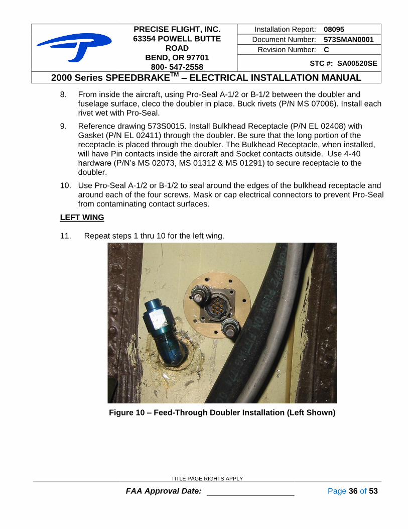
8. From inside the aircraft, using Pro-Seal A-1/2 or B-1/2 between the doubler and fuselage surface, cleco the doubler in place. Buck rivets (P/N MS 07006). Install each rivet wet with Pro-Seal.
9. Reference drawing 573S0015. Install Bulkhead Receptacle (P/N EL 02408) with Gasket (P/N EL 02411) through the doubler. Be sure that the long portion of the receptacle is placed through the doubler. The Bulkhead Receptacle, when installed, will have Pin contacts inside the aircraft and Socket contacts outside. Use 4-40 hardware (P/N’s MS 02073, MS 01312 & MS 01291) to secure receptacle to the doubler.
10. Use Pro-Seal A-1/2 or B-1/2 to seal around the edges of the bulkhead receptacle and around each of the four screws. Mask or cap electrical connectors to prevent Pro-Seal from contaminating contact surfaces.
LEFT WING 11. Repeat steps 1 thru 10 for the left wing.
Figure 10 – Feed-Through Doubler Installation (Left Shown)

PRECISE FLIGHT, INC.
63354 POWELL BUTTE
ROAD
BEND, OR 97701
800- 547-2558
Installation Report: 08095
Document Number: 573SMAN0001
Revision Number: C
STC #: SA00520SE
2000 Series SPEEDBRAKETM – ELECTRICAL INSTALLATION MANUAL
TITLE PAGE RIGHTS APPLY
FAA Approval Date: Page 37 of 53
2.12 WIRING THE SPEEDBRAKE™ CARTRIDGES TO THE ALC
TOOLS REQUIRED
Volt-Ohm Meter Wire Crimper, Cutter, Stripper Extraction Tool: MS24256R20
Insertion Tool: MS24256A20 Ruler: 12 inch Screwdriver: #1 Phillips, Flat
Crimper: M22520/1-01 with M22520/1-02 turret or
Crimper: M22520/2-01 with M22520/2-02 positioner or
Crimper: M22520/7-01 with M22520/7-02 positioner
PARTS REQUIRED
Part Number Qty Description PFI Number
573S0001 1 Drawing – Speedbrake Installation -
573S0004 1 Drawing – System Schematic -
573S0021-1 2 Wire harness Assembly -
66506 16* Pin Contact, Crimp style EL 02413
66570 16* Pin Contact, Solder style EL 01725
1-206062-6 2 CPC Backshell EL 01727
205841-2 2 CPC Receptacle EL 01729
91067-2 1 Pin Insertion Tool EL 01773
MS3126F12-10S 2 Cannon Plug Assy. (w/sockets) EL 02409
MS3126F12-10P 2 Cannon Plug Assy. (w/pins) EL 02410
9421 A/R 8-Conductor 22 GA Cable SP 02029 * See Packing List. Crimp or Solder style may be used
! CAUTION ! Be sure to keep wiring harness clear of control cables, and clear of fuel
lines. Secure the wire according to AC 43.13-1(B), Chapter 11.
RIGHT WING, OUTSIDE CABIN 1. From the SpeedBrake access hole in the right wing, run the wire harness (P/N
573S0021-1) through the center of the existing wing stringers, to the wing root bulkhead connector, with the installed wire harness plug on the SpeedBrake end.
2. Secure the wire harness with Adel clamps if necessary.
3. At the wing root, strip the wiring harness jacket back exposing 5/8” of conductors.
4. Insert the ends through the strain relief of Cannon plug (P/N EL 02410).
5. Remove 1/8” of insulation from all conductors.
6. Crimp the end of each wire to a pin contact (M39029/31-240), supplied with Cannon plug assembly (P/N EL 02410).

PRECISE FLIGHT, INC.
63354 POWELL BUTTE
ROAD
BEND, OR 97701
800- 547-2558
Installation Report: 08095
Document Number: 573SMAN0001
Revision Number: C
STC #: SA00520SE
2000 Series SPEEDBRAKETM – ELECTRICAL INSTALLATION MANUAL
TITLE PAGE RIGHTS APPLY
FAA Approval Date: Page 38 of 53
7. Refer to drawing 573S0004 or figure 11 for wire color to bulkhead connector pin code. Insert the pins into their respective holes in the Cannon plug (P/N EL 02410) using MS24256 insertion tool.
8. Attach the strain relief clamp to the plug. Tighten the strain relief to the jacket. Check for pin continuity with a Volt-Ohm meter.
9. Connect the Cannon plug and bulkhead receptacle together.
LEFT WING, OUTSIDE CABIN 10. Repeat steps 1 thru 9 for the left wing.
RIGHT WING, INSIDE CABIN 11. On the cabin side of the right wing root, at the bulkhead receptacle, route the 8-
Conductor 22 GA cable (P/N SP 02029) parallel to the existing wire harness, along the co-pilot’s sidewall wiring harness forward to the ALC.
12. At the bulkhead receptacle, strip the 8-conductor cable jacket back, exposing 5/8” of conductors.
13. Insert the ends through the strain relief in Cannon plug (P/N EL 02409).
14. Remove 1/8” of insulation from all conductors.
15. Crimp the end of each wire to the short end of a socket (LP-597820-355), supplied with Cannon plug (P/N EL 02409).
16. Referring to drawing 573S0004 or figure 11 for cable color to bulkhead connector pin code, insert the sockets into their respective holes in the plug in Cannon plug (P/N EL 02409).
17. Attach the strain relief clamp to the plug. Tighten the strain relief to the jacket. Check for contact continuity with a Volt-Ohm meter.
18. Connect the Cannon plug and bulkhead receptacle together.
19. On the ALC end of the 8-Conductor cable, cut the cable to length and strip the jacket back exposing 5/8” of conductors.
20. Insert the ends through the CPC backshell (P/N EL 01727).
21. Remove 1/8” of insulation from all conductors.
22. Crimp the end of each wire to a 66506 pin (P/N EL 02413), or solder each wire to a 66570 pin (P/N EL 01725).
23. Referring to drawing 573S0004 or figure 11 for wire color to AMP connector pin code, insert the pins into their respective holes in the CPC receptacle housing (P/N EL 01729). Use the red end of the pin insertion tool (P/N EL 01773) to insert contacts, use the white end to extract contacts from the housing.

PRECISE FLIGHT, INC.
63354 POWELL BUTTE
ROAD
BEND, OR 97701
800- 547-2558
Installation Report: 08095
Document Number: 573SMAN0001
Revision Number: C
STC #: SA00520SE
2000 Series SPEEDBRAKETM – ELECTRICAL INSTALLATION MANUAL
TITLE PAGE RIGHTS APPLY
FAA Approval Date: Page 39 of 53
24. Attach the CPC backshell (P/N EL 01727) to the receptacle (P/N EL 01729). Tighten the strain relief to the jacket. Check for contact continuity with a Volt-Ohm meter.
LEFT WING, INSIDE CABIN 25. Repeat steps 12-24 for the left wing. For Step 11 route the 8-conductor cable along
existing wiring harnesses, across the instrument panel, or across the aft side of the forward wing spar under the floorboards, to the co-pilot's side panel. Then route the cable along the co-pilot's sidewall with the other SpeedBrake wire harness to the ALC.
! CAUTION ! Be sure to keep wiring harness clear of control cables and fuel lines.
Figure 11 – Connector Pinouts (Reference Only)

PRECISE FLIGHT, INC.
63354 POWELL BUTTE
ROAD
BEND, OR 97701
800- 547-2558
Installation Report: 08095
Document Number: 573SMAN0001
Revision Number: C
STC #: SA00520SE
2000 Series SPEEDBRAKETM – ELECTRICAL INSTALLATION MANUAL
TITLE PAGE RIGHTS APPLY
FAA Approval Date: Page 40 of 53
2.13 WIRING THE ASYMMETRIC LOGIC CONTROL (ALC)
TOOLS REQUIRED
AC 43.13-1(B) Chap. 11 Crimp tool: AMP E9818 Needle Nose Pliers
Screwdriver: #1 Phillips, Flat Wire Crimper, Cutter, and Stripper
PARTS REQUIRED
Part Number Qty Description PFI Number
573S0004 1 Drawing -
205838-1 1 Connector housing, plug, CPC #11, 8 sockets EL 01726
206062-1 1 Connector, backshell, CPC #11 EL 01727
66504 8* Socket Contact, Crimp style EL 02414
66569 8* Socket Contact, Solder style EL 01728
91067-2 1 Pin Insertion Tool EL 01773
9421 A/R 8-Conductor 22 GA Cable SP 02029 * See Packing List. Crimp or Solder style may be used.
1. Route the remaining 8-conductor 22 GA cable (P/N SP 02029) from the ALC location in the co-pilot cabin floor, along the co-pilot’s side-wall, behind the instrument panel through existing wire bundles, and into the circuit breaker panel on the pilot's side-wall. Leave sufficient slack behind the instrument panel to connect the circuit breaker, switch, and annunciator. Cut the 8-conductor cable to length and save the remainder. Secure the wire according to AC 43.13-1(B), Chapter 11.
2. On the ALC end of the 8-conductor wiring harness, strip the jacket back exposing 5/8” of conductors.
3. Remove 1/8” of insulation from all conductors.
4. Crimp the end of each wire to a 66504 socket (P/N EL 01728), or solder each wire to a 66569 socket (P/N EL 01728).
5. Insert the end through a CPC backshell (P/N EL 01727).
6. Referring to drawing 573S0004 or figure 11 for wire color to AMP connector pin code, insert the sockets into their respective holes in the plug housing (P/N EL 01726) using the pin insertion tool (P/N EL 01773).
7. Attach the backshell (P/N EL 01727) to the Plug (P/N EL 01726). Tighten the strain relief to the jacket. Check for contact continuity with a Volt-Ohm meter.
8. Connect the wire harness plug and ALC plug J1 together.
Check to ensure that cable routing does not interfere with any other aircraft system.

PRECISE FLIGHT, INC.
63354 POWELL BUTTE
ROAD
BEND, OR 97701
800- 547-2558
Installation Report: 08095
Document Number: 573SMAN0001
Revision Number: C
STC #: SA00520SE
2000 Series SPEEDBRAKETM – ELECTRICAL INSTALLATION MANUAL
TITLE PAGE RIGHTS APPLY
FAA Approval Date: Page 41 of 53
2.14 CIRCUIT BREAKER AND SWITCH
TOOLS REQUIRED
AC 43.13-1(B) Chap. 11 Drill Bits: 7/16” & 5/8” Unibit
Drill Motor Needle Nose Pliers Solder: Rosin Core
Soldering Iron Wire Crimper, Cutter, & Stripper
PARTS REQUIRED
Part Number Qty Description PFI Number
573S0002 1 Drawing – Cockpit Control Installation -
573S0004 1 Drawing – System Schematic -
7277-2-3 1 Circuit breaker, 3A EL 01270
300S0008-1 1* Placard, Switch -
9803-11 1* Switch, 2PDT Toggle EL 02412
7101J61ZQE22 1* Switch, Lever EL 02637
5821A0B0C3F4L5N1 (A) P11,13 SPEED,BRAKE
1 Annunciator EL 02404
* See Packing List
1. At the circuit breaker panel, install and wire the circuit breaker (P/N EL 01270). Reference drawing 573S0004 for proper wiring.
2. Install switch option in accordance with drawing 573S0002-1, or -2. See packing list for part numbers actually ordered.
3. Install the annunciator (P/N EL 02404) within full view of the pilot. Use drawing 573S0002-1 for reference.
4. Using the wire run in the previous section, wire the annunciator, circuit breaker, ground, and switch using drawing 573S0004 for reference.
5. Ring out all harnesses and wiring to ensure good connections.
NOTE Wire may be separated or pulled from the wire harness outer shielding and
run to the individual items. Use heat shrink to seal separated shielding. ALTERNATIVELY, new wire may be run to the individual items.
NOTE For switch and light locations other than shown, obtain separate FAA
engineering approval, or provide a deviation statement on the 337 submitted for approval.
PRECISE FLIGHT, INC.
63354 POWELL BUTTE
ROAD
BEND, OR 97701
800- 547-2558
Installation Report: 08095
Document Number: 573SMAN0001
Revision Number: C
STC #: SA00520SE
2000 Series SPEEDBRAKETM – ELECTRICAL INSTALLATION MANUAL
TITLE PAGE RIGHTS APPLY
FAA Approval Date: Page 42 of 53
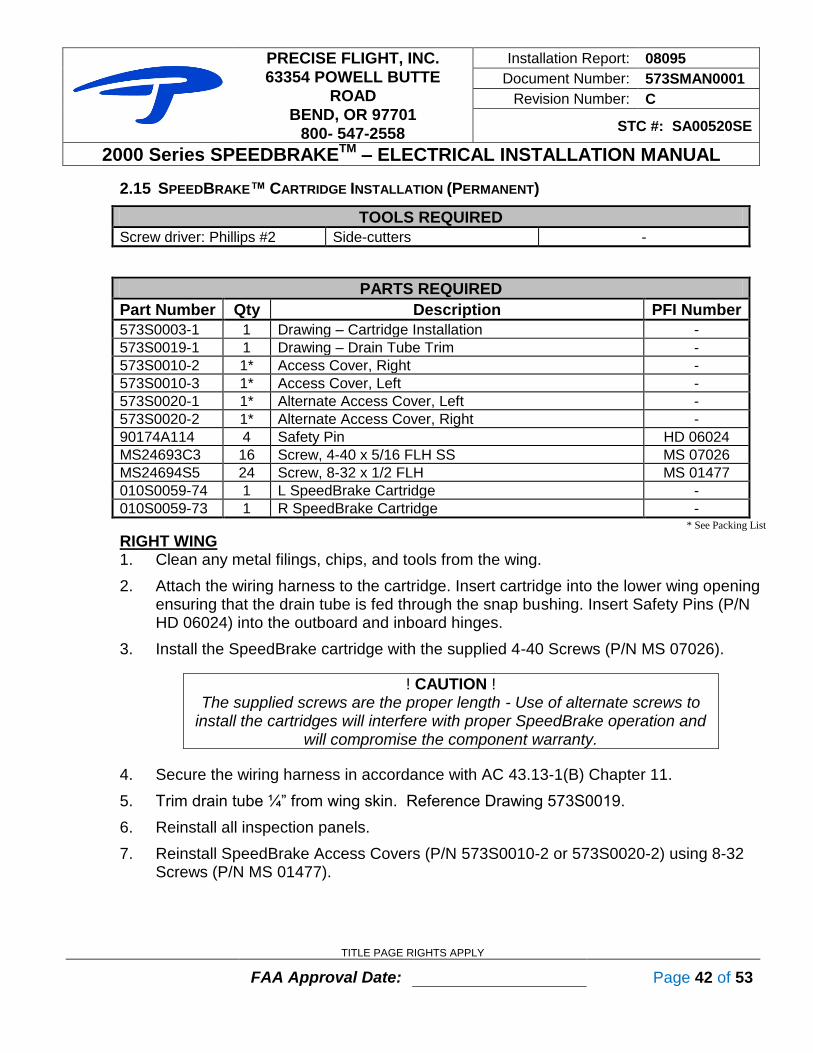
2.15 SPEEDBRAKE™ CARTRIDGE INSTALLATION (PERMANENT)
TOOLS REQUIRED
Screw driver: Phillips #2 Side-cutters -
PARTS REQUIRED
Part Number Qty Description PFI Number
573S0003-1 1 Drawing – Cartridge Installation -
573S0019-1 1 Drawing – Drain Tube Trim -
573S0010-2 1* Access Cover, Right -
573S0010-3 1* Access Cover, Left -
573S0020-1 1* Alternate Access Cover, Left -
573S0020-2 1* Alternate Access Cover, Right -
90174A114 4 Safety Pin HD 06024
MS24693C3 16 Screw, 4-40 x 5/16 FLH SS MS 07026
MS24694S5 24 Screw, 8-32 x 1/2 FLH MS 01477
010S0059-74 1 L SpeedBrake Cartridge -
010S0059-73 1 R SpeedBrake Cartridge - * See Packing List
RIGHT WING 1. Clean any metal filings, chips, and tools from the wing.
2. Attach the wiring harness to the cartridge. Insert cartridge into the lower wing opening ensuring that the drain tube is fed through the snap bushing. Insert Safety Pins (P/N HD 06024) into the outboard and inboard hinges.
3. Install the SpeedBrake cartridge with the supplied 4-40 Screws (P/N MS 07026).
! CAUTION ! The supplied screws are the proper length - Use of alternate screws to
install the cartridges will interfere with proper SpeedBrake operation and will compromise the component warranty.
4. Secure the wiring harness in accordance with AC 43.13-1(B) Chapter 11.
5. Trim drain tube ¼” from wing skin. Reference Drawing 573S0019.
6. Reinstall all inspection panels.
7. Reinstall SpeedBrake Access Covers (P/N 573S0010-2 or 573S0020-2) using 8-32 Screws (P/N MS 01477).
PRECISE FLIGHT, INC.
63354 POWELL BUTTE
ROAD
BEND, OR 97701
800- 547-2558
Installation Report: 08095
Document Number: 573SMAN0001
Revision Number: C
STC #: SA00520SE
2000 Series SPEEDBRAKETM – ELECTRICAL INSTALLATION MANUAL
TITLE PAGE RIGHTS APPLY
FAA Approval Date: Page 43 of 53
LEFT WING 8. Repeat Step 1 through 7 for the left wing.
NOTE Reference Piper Maintenance Manual when reinstalling Pitot tube and
Access Cover (P/N 573S0010-3 or 573S0020-1).
9. Check to ensure that cable routing does not interfere with any other aircraft system.

PRECISE FLIGHT, INC.
63354 POWELL BUTTE
ROAD
BEND, OR 97701
800- 547-2558
Installation Report: 08095
Document Number: 573SMAN0001
Revision Number: C
STC #: SA00520SE
2000 Series SPEEDBRAKETM – ELECTRICAL INSTALLATION MANUAL
TITLE PAGE RIGHTS APPLY
FAA Approval Date: Page 44 of 53
SPEEDBRAKE
2.16 PLACARDS INSTALLATION
TOOLS REQUIRED
Isopropyl alcohol - -
PARTS REQUIRED
Part Number Qty Description PFI Number
- 1 Placard, SB Equipped PL 00456
010S0200-1 1 Placard, SpeedBrake -
573S0016-1 2* Placard, Elect. Act. – Large -
- 2* Placard, Elect. Act. – Small PL 01750 * See Packing List
NOTE: Use Isopropyl alcohol to prepare surface before applying placard. 1. Install Placard (P/N PL 00456) in full view of the pilot.
2. Install Placard (010S0200-1) at SpeedBrake circuit breaker.
3. Install Placard (573S0016-1) on wing skin aft of SpeedBrake cartridges.
Or alternate Placard (P/N PL 01750)
SPEEDBRAKE EQUIPPED: FOR OPERATING INSTRUCTIONS & LIMITATIONS
SEE SUPPLEMENT IN OWNERS MANUAL OR OPERATING HANDBOOK.
Electrically Actuated - DO NOT MANUALLY OPERATE
Electrically Actuated - DO NOT MANUALLY OPERATE

PRECISE FLIGHT, INC.
63354 POWELL BUTTE
ROAD
BEND, OR 97701
800- 547-2558
Installation Report: 08095
Document Number: 573SMAN0001
Revision Number: C
STC #: SA00520SE
2000 Series SPEEDBRAKETM – ELECTRICAL INSTALLATION MANUAL
TITLE PAGE RIGHTS APPLY
FAA Approval Date: Page 45 of 53
2.17 SPEEDBRAKE OPERATIONAL TEST
1. Reconnect all electrical power. Check that SpeedBrake switch is set to DOWN.
2. Turn on aircraft master power switch.
3. Check that SpeedBrake circuit breaker is pushed in, and SpeedBrake annunciator is not illuminated.
4. Toggle SpeedBrake switch to UP and check that both SpeedBrake cartridges fully deploy and remain up.
5. Check that the SpeedBrake Annunciator has illuminated and dimming works as required.
6. Toggle SpeedBrake switch to DOWN, and check that both SpeedBrake cartridges have returned to the fully closed position and remain closed.
7. Check that the SpeedBrake annunciator has turned off.
8. Toggle the SpeedBrake switch to UP, and pull the SpeedBrake circuit breaker just as the SpeedBrakes begin to leave the cartridge. Check that the SpeedBrake blades drop promptly to the closed position.
9. Push the SpeedBrake circuit breaker back in and cycle the SpeedBrake switch from DOWN to UP. Observe that the SpeedBrakes deploy to the fully opened position.
10. Repeat Steps 6 and 7 to retract SpeedBrakes.
11. Turn off aircraft master power switch.
12. If any problems occur, consult the TROUBLE SHOOTING GUIDE section.
13. Re-install all interior and exterior panels, and aircraft interior.

PRECISE FLIGHT, INC.
63354 POWELL BUTTE
ROAD
BEND, OR 97701
800- 547-2558
Installation Report: 08095
Document Number: 573SMAN0001
Revision Number: C
STC #: SA00520SE
2000 Series SPEEDBRAKETM – ELECTRICAL INSTALLATION MANUAL
TITLE PAGE RIGHTS APPLY
FAA Approval Date: Page 46 of 53
2.18 DOCUMENTATION
Before performing flight tests it is recommended you complete the calculations for weight and balance and revise the equipment list showing installation of Precise Flight SpeedBrakes™. Complete FAA Form 337 and submit to the FAA as required. 1. Complete calculations for Weight and Balance for SpeedBrakes™ cartridge
installation weight is 8lbs at 178.0 in. and Precise Flight ALC weight is 1lb at 120.0 in.
2. Perform an electrical load analysis to determine Speedbrakes do not cause electrical bus load to exceed 80% of the capacity of the electrical system. The SpeedBrakes draw a maximum of 3A while the SpeedBrakes are in motion. Continuous loads are listed in section 6.
3. Update aircraft equipment list with the installation of the Precise Flight SpeedBrakes™.
4. Add the FAA approved Flight Manual Supplement to the aircraft Flight manual.
5. Record installation in appropriate aircraft maintenance records (See Figure 12 for suggested FAA Form 337 description of work).
6. Keep all Precise Flight 2000 Series SpeedBrakes™ papers with aircraft records.
7. Complete warranty information at http://preciseflight.com/support/warranty.

PRECISE FLIGHT, INC.
63354 POWELL BUTTE
ROAD
BEND, OR 97701
800- 547-2558
Installation Report: 08095
Document Number: 573SMAN0001
Revision Number: C
STC #: SA00520SE
2000 Series SPEEDBRAKETM – ELECTRICAL INSTALLATION MANUAL
TITLE PAGE RIGHTS APPLY
FAA Approval Date: Page 47 of 53
8. Description of Work Accomplished
(If more space is required, attach additional sheets. Identify with aircraft nationality and registration mark and date work completed.)
A. The following components were installed: PRECISE FLIGHT 2000 Series Electric SpeedBrake
TM Kit per STC
SA00520SE, installation Kit # __________. B. Installed the Precise Flight SpeedBrake system in accordance with
SpeedBrake® 2000 Installation Instructions for the PA-46 PIPER MALIBU / MALIBU MIRAGE / MALIBU MATRIX (STC SA00520SE), Precise Flight Installation Report 08095, Revision C, or later FAA approved revision. Guidance in FAA Advisory Circulars AC43.13-1(B) Chapter 11, and AC43.13-2(B) Chapters 1 and 2.
C. An electrical load analysis was performed and the revised continuous load of
the aircraft electrical bus (generator or other supply) does not exceed 80% of capacity or in accordance with the procedures in FAA AC43.13-1(B) Chapter 11.
D. A complete operational test was performed according to the SPEEDBRAKE
Installation Report 08095. The equipment performed satisfactorily and did not adversely affect existing components or systems in the aircraft (EMI/RFI) as required by FAR 23.1301, FAR 23.1431.
E. The aircraft equipment list was revised to reflect these changes; weight and
balance data was revised and placed in the aircraft records. A Precise Flight
Inc. SPEEDBRAKE Aircraft Flight Manual Supplement dated ______was placed in the aircraft. Installed weight includes 8lbs at STA 178.0in, and 1lbs at STA 120.0in.
Figure 12 - Suggested FAA Form 337 Description of Work Statement

PRECISE FLIGHT, INC.
63354 POWELL BUTTE
ROAD
BEND, OR 97701
800- 547-2558
Installation Report: 08095
Document Number: 573SMAN0001
Revision Number: C
STC #: SA00520SE
2000 Series SPEEDBRAKETM – ELECTRICAL INSTALLATION MANUAL
TITLE PAGE RIGHTS APPLY
FAA Approval Date: Page 48 of 53
3.0 TROUBLE SHOOTING GUIDE
3.1 SPEEDBRAKE CARTRIDGE FAILS TO OPERATE CORRECTLY
a. Check circuit breaker. b. Check cannon and CPC plugs for security. c. Check all cannon and CPC plugs for correct wiring (See Drawing 573S0004
for electrical installation procedures); ensure contacts are fully seated within connector housing and that wires are properly crimped.
d. Check that system voltage is adequate (no less than 11 or 22 VDC.) The ALC is designed to disengage the SpeedBrake blades should either cartridge fail to fully deploy within a few seconds. Low voltage, or corroded connectors, may cause the ALC to time out, to retract the blades or behave erratically.
e. The wing harness connectors, J2 or J3, may be reversed at the ALC to isolate a problem to a specific cartridge or the ALC. (This would cause the right cartridge to indicate as the left, and left as right, if separate annunciation is used.)
f. A SpeedBrake cartridge may be removed from the wing and plugged directly into the ALC at connector P2 or P3 to isolate a harness failure.
g. If SpeedBrake doors open, check that doors stop approximately ¼” before being fully vertical. There should be no gap between the SpeedBrake doors. If doors open beyond this position, call Precise Flight, Inc.
3.2 WARNINGS
!! WARNING !! Do not operate the SpeedBrakes™ by hand while electrical power is
on. Damage to cartridges and personal injuries may result!
!! WARNING !! Do not use spray lubricants on SpeedBrakes™. Damage to cartridges
and SpeedBrake clutch or motor may result!
3.3 FOR ADDITIONAL TECHNICAL ASSISTANCE
Please call Precise Flight, Inc. 800-547-2558 Additional information and products are available on the web, at http://www.preciseflight.com or email us at [email protected]

PRECISE FLIGHT, INC.
63354 POWELL BUTTE
ROAD
BEND, OR 97701
800- 547-2558
Installation Report: 08095
Document Number: 573SMAN0001
Revision Number: C
STC #: SA00520SE
2000 Series SPEEDBRAKETM – ELECTRICAL INSTALLATION MANUAL
TITLE PAGE RIGHTS APPLY
FAA Approval Date: Page 49 of 53
4.0 INSTRUCTIONS FOR CONTINUED AIRWORTHINESS
4.1 INTRODUCTION
The content of this section provides the instructions for continued airworthiness for the SpeedBrake
® 2000 Series system installation. Because a majority of the installation does
not affect the standard airworthiness of the aircraft, only the key items that are different are noted in this section. All structure and general maintenance must be performed in accordance with existing approved maintenance practices, or the aircraft maintenance manual.
4.2 SYSTEM DESCRIPTION
The Series 2000 SpeedBrake® option consists of wing mounted electric SpeedBrake
®
cartridges. Each SpeedBrake cartridge is interconnected electronically by a central logic-switching unit and the yoke or panel mounted SpeedBrake actuator switch. The SpeedBrake
® cartridges receive electrical power from the aircraft electrical buss through a
disconnect type circuit breaker. The Precise Flight SpeedBrake
® 2000 system is installed to provide expedited descents at
cruise power, glide path control on final approach, airspeed reduction, and an aid to the prevention of excessive engine cooling during descent. The SpeedBrakes can be extended at aircraft speeds up to Vne. The SpeedBrake annunciator is located near the airspeed indicator. The SpeedBrake switch is activated ON to fully deploy and OFF to retract the SpeedBrakes. The annunciation indicates deployment when both SpeedBrake
® units are deployed. A failure of
a single cartridge drive unit will prevent the Annunciator light from illuminating.
Figure 13 – SpeedBrake Annunciator Switch

PRECISE FLIGHT, INC.
63354 POWELL BUTTE
ROAD
BEND, OR 97701
800- 547-2558
Installation Report: 08095
Document Number: 573SMAN0001
Revision Number: C
STC #: SA00520SE
2000 Series SPEEDBRAKETM – ELECTRICAL INSTALLATION MANUAL
TITLE PAGE RIGHTS APPLY
FAA Approval Date: Page 50 of 53
The annunciator will light after the SpeedBrake® switch is toggled ON and both brakes are
in the up position. If the annunciator fails to light and both brakes do not extend after the switch is toggled, it indicates a failure of one SpeedBrake
® cartridge and the SpeedBrake
®
switch should be toggled OFF. The system can be checked again for proper operation, but after the second attempt, the SpeedBrake
® switch should be left OFF. When the
SpeedBrake® Switch is OFF, the annunciator will extinguish when both brakes are fully
stowed in the wing.
4.3 SPECIAL TOOLS REQUIRED
Refer to Table 1 and Table 2 of this document for a list of special tools and materials required for installation and maintenance of the SpeedBrake
® 2000 system.
4.4 MAINTENANCE INSTRUCTIONS
Maintain aircraft structure, and wiring in accordance with aircraft maintenance manual, and FAA AC 43.13. Access to the SpeedBrake installation is through the lower access panel installed per section 2 of this document.
4.5 TROUBLE SHOOTING GUIDE
Refer to Section 3 of this document for trouble shooting guide.
4.6 AIRWORTHINESS LIMITATIONS
The Airworthiness Limitations section (Section 4.0) is FAA Approved and Specifies maintenance required under Sections 43.16 and 91.403 of the
Federal Aviation Regulations unless an alternative program has been FAA Approved.
None – The operation of the SpeedBrake
® System does not impact the airworthiness
limitations and is not required for normal flight.
4.7 SCHEDULED MAINTENANCE INTERVALS AND INSPECTIONS FOR CONTINUED AIRWORTHINESS
This section includes the inspection intervals, and requirements, for maintenance of the SpeedBrake
® 2000 system when installed in the aircraft. The breakdown of required
inspections is listed in Table 4.

PRECISE FLIGHT, INC.
63354 POWELL BUTTE
ROAD
BEND, OR 97701
800- 547-2558
Installation Report: 08095
Document Number: 573SMAN0001
Revision Number: C
STC #: SA00520SE
2000 Series SPEEDBRAKETM – ELECTRICAL INSTALLATION MANUAL
TITLE PAGE RIGHTS APPLY
FAA Approval Date: Page 51 of 53
Table 4 - Scheduled Maintenance Intervals and Inspections
EACH 5000
HOURS
EACH 1000
HOURS
ANNUALLY
EACH 100
HOURS
EACH 50
HOURS
PIPER MALIBU / MALIBU MIRAGE / MALIBU MATRIX
SPEEDBRAKE 2000 TM
1. Check Cap Strip Cover screws for security, if loose, remove screws and apply Loctite 262, re-torque to 8 in-lbs. Check SpeedBrake top attachment screws for security, if loose, remove screws and apply Loctite 262, re-torque to 8 in-lbs.
2. Check drain tubes for debris O
3. a.) Remove inspection plates b.) Disconnect electrical plugs c.) Remove SpeedBrakes
TM from aircraft
d.) Clean and Inspect unit for damage, corrosion, looseness & proper operation
e.) Lubricate worm and worm gear with AeroShell 22. DO NOT USE SPRAY LUBRICANTS! f.) Reinstall SpeedBrakes
TM in aircraft
g.) Connect electrical plugs h.) Install inspection plate i.) Check for proper placards
4. a.) Remove inspection plates b.) Disconnect electrical plugs c.) Remove SpeedBrakes
TM from aircraft
d.) Return SpeedBrakesTM to Precise Flight Inc. for
Clutch Lubrication and Spring Replacement e.) Reinstall SpeedBrakes
TM in aircraft
f.) Connect electrical plugs g.) Install inspection plate h.) Perform operational check per Section 2
5. a.) Remove inspection plates b.) Disconnect electrical plugs c.) Remove SpeedBrakesTM from aircraft d.) Return SpeedBrakes
TM to Precise Flight Inc. for
Drive Assembly Replacement e.) Reinstall SpeedBrakesTM in aircraft f.) Connect electrical plugs g.) Install inspection plate h.) Perform operational check per Section 2

PRECISE FLIGHT, INC.
63354 POWELL BUTTE
ROAD
BEND, OR 97701
800- 547-2558
Installation Report: 08095
Document Number: 573SMAN0001
Revision Number: C
STC #: SA00520SE
2000 Series SPEEDBRAKETM – ELECTRICAL INSTALLATION MANUAL
TITLE PAGE RIGHTS APPLY
FAA Approval Date: Page 52 of 53
5.0 REFERENCES
1. FAA AC43.13-1, Acceptable Methods, Techniques, and Practices – Aircraft Inspection and Repair, Revision B Chg 1, September 2001 (or later FAA approved revision).
2. FAA AC43.13-2, Acceptable Methods, Techniques, and Practices – Aircraft Alterations, Revision B, March 2008 (or later FAA approved revision).
3. Federal Aviation Regulations Part 23 (FAR 23) Effective 1 February 1965 Including Amendments 23-1 through 22-59, Airworthiness Standards: Normal, Utility, Acrobatic, and Commuter Category Airplanes, Department of Transportation, Federal Aviation Administration
4. Federal Aviation Regulations Part 43 (FAR 43) Effective 8 August 2006 Including Amendments 43-0 through 43-44, Maintenance, Preventive Maintenance, Rebuilding, and Alteration, Department of Transportation, Federal Aviation Administration

PRECISE FLIGHT, INC.
63354 POWELL BUTTE
ROAD
BEND, OR 97701
800- 547-2558
Installation Report: 08095
Document Number: 573SMAN0001
Revision Number: C
STC #: SA00520SE
2000 Series SPEEDBRAKETM – ELECTRICAL INSTALLATION MANUAL
TITLE PAGE RIGHTS APPLY
FAA Approval Date: Page 53 of 53
6.0 APPENDICES
6.1 ELECTRICAL LOADS ANALYSIS FORM:
ELECTRICAL LOAD ANALYSIS
MODEL
S/N
DATE
The following provides additional information to revise the existing aircraft Electrical Load Analysis.
The following is a list of SpeedBrake components that place a continuous load on the aircraft circuitry. It is recommended that under no condition shall the total continuous electrical load be more than 80% of total alternator capacity. Revise existing electrical load analysis, or create a new list
OPTIONAL EQUIPMENT NO. OF UNITS AMPERES PER UNIT
SpeedBrake Clutch - 24 VDC 2 0.12 SpeedBrake Clutch - 12 VDC 2 0.24 SpeedBrake Annunciator Lights 1 0.08
The following is a list of SpeedBrake components that place an intermittent load on the aircraft circuitry. Do not include these items when computing the total electrical load.
INTERMITTENT LOAD EQUIPMENT NO. OF UNITS AMPERES PER UNIT
SpeedBrake Drive -24V 2 1.0 SpeedBrake Drive -12V 2 2.0
NO. AMPERAGE
EXISTING AIRCRAFT CONTINUOUS LOAD
REVISED AIRCRAFT CONTINUOUS LOAD
NOTE: Please ensure that the revised Electrical Load is in accordance with the procedures in FAA Advisory Circular 43.13-1(B), Chapter 11.