Does Unmanned Make Unacceptable? Exploring the Debate on ...
20Echo Cancellation
Multiple access communication, discussed in Chapter 17, usually relies on theorthogonality of the different signals by separating them in time or frequency. Analogoustechniques apply to full-duplex transmission, or simultaneous transmission in both directionson a point-to-point link. Specifically, we can use time-compression multiplexing (TCM) andfrequency-division multiplexing (FDM). A more efficient approach, echo cancellation enablestransmission in two directions simultaneously using the same frequency band, thereby reducingthe bandwidth requirements approximately in half relative to TCM and FDM.
Example 20-1. Full-duplex digital transmission on a single wire pair from central office totelephone subscriber (the digital subscriber loop), as standardized in the United States, uses four-level baseband transmission. Given the communication engineer’s penchant for obfuscation, this iscalled “2B1Q” line coding, which stands for “two bits on one quaternary digit”. The bit rate is 160kb ⁄ s, including 144 kb ⁄ s user data and 16 kb ⁄ s for framing and control, and the baud rate istherefore 80 kb ⁄ s. The bandwidth required on the cable is, for 0% excess bandwidth, 40 kHz. Bothdirections of transmission share this same bandwidth, with echo cancellation used to separate thetwo directions. See [1][2][3] for comparisons of the relative merits of echo cancellation and TCM inthis application.
Example 20-2. The V.32 full-duplex modem transmits 9600 b ⁄ s in both directions over avoiceband data channel. It uses a baud rate of 2400 Hz, with four bits per symbol, and uses QAMmodulation with a carrier frequency of 1800 Hz. With 0% excess bandwidth, the frequency bandused would therefore be from 400 to 3000 Hz, nearly the full bandwidth of the voiceband datachannel. TCM is unsuitable for voiceband data transmission because of the possibility of largepropagation delays (such as on connections including a satellite link), and FDM is too bandwidthinefficient for higher speed modems.
At each end of a full-duplex link, the near-end transmitted signal can be used to eliminate theundesired interference (called an echo) of the near-end transmitted signal at the receiver. Anecho canceler can learn adaptively the response from near-end transmitter to receiver, generate
946 Echo Cancellation
a replica of that echo, and subtract that echo replica from the receiver input to yield aninterference-free signal.
Example 20-3. In principle, echo cancellation could be used to share any medium, such as a radiochannel (Section 18.4), for the two directions. A radio channel would be of great practical interestbecause of the limited available spectrum, but unfortunately is impractical in today’s technologybecause the speed, and particularly the accuracy, required for the echo cancellation. However, wecannot rule it out for the future.
20 .1 . PRINCIPLE OF THE ECHO CANCELER
When we transmit full-duplex data, the primary problem is undesired feed-through of thetransmitted data signal into the receiver through the hybrid. This extraneous signal is calledecho. The operation of the hybrid was discussed in Section 18.5, and in particular it wasillustrated in Fig. 18-37, where the mechanism for echo was stated to be a mismatch betweenthe impedance of the two-wire cable and the hybrid balancing impedance.
Example 20-4. As shown in Fig. 18-39, there are actually two opportunities for undesired echo ona voiceband data connection — the near-end hybrid and one or more far-end hybrids. One difficultywith the far-end echo that we will have to address is the possible frequency offset that it experiences,just as with the far-end data signal. The digital subscriber loop application is easier than thevoiceband data canceler in this respect, since there is no far-end echo mechanism.
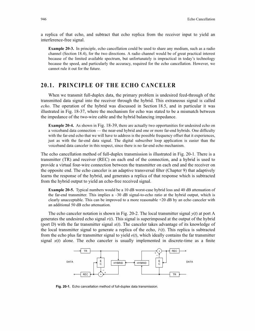
The echo cancellation method of full-duplex transmission is illustrated in Fig. 20-1. There is atransmitter (TR) and receiver (REC) on each end of the connection, and a hybrid is used toprovide a virtual four-wire connection between the transmitter on each end and the receiver onthe opposite end. The echo canceler is an adaptive transversal filter (Chapter 9) that adaptivelylearns the response of the hybrid, and generates a replica of that response which is subtractedfrom the hybrid output to yield an echo-free received signal.
Example 20-5. Typical numbers would be a 10 dB worst-case hybrid loss and 40 dB attenuation ofthe far-end transmitter. This implies a –30 dB signal-to-echo ratio at the hybrid output, which isclearly unacceptable. This can be improved to a more reasonable +20 dB by an echo canceler withan additional 50 dB echo attenuation.
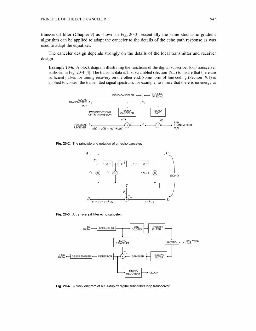
The echo canceler notation is shown in Fig. 20-2. The local transmitter signal y(t) at port Agenerates the undesired echo signal r(t). This signal is superimposed at the output of the hybrid(port D) with the far transmitter signal x(t). The canceler takes advantage of its knowledge ofthe local transmitter signal to generate a replica of the echo, (t). This replica is subtractedfrom the echo plus far transmitter signal to yield e(t), which ideally contains the far transmittersignal x(t) alone. The echo canceler is usually implemented in discrete-time as a finite
Fig. 20-1. Echo cancellation method of full-duplex data transmission.
DATADATA ECC
EHYBRIDHYBRID
REC
REC TR
TR
+–
+
+–
+
r
PRINCIPLE OF THE ECHO CANCELER 947
transversal filter (Chapter 9) as shown in Fig. 20-3. Essentially the same stochastic gradientalgorithm can be applied to adapt the canceler to the details of the echo path response as wasused to adapt the equalizer.
The canceler design depends strongly on the details of the local transmitter and receiverdesign.
Example 20-6. A block diagram illustrating the functions of the digital subscriber loop transceiveris shown in Fig. 20-4 [4]. The transmit data is first scrambled (Section 19.5) to insure that there aresufficient pulses for timing recovery on the other end. Some form of line coding (Section 19.1) isapplied to control the transmitted signal spectrum; for example, to insure that there is no energy at
Fig. 20-2. The principle and notation of an echo canceler.
RECEIVERTO LOCAL
FARTRANSMITTER
LOCAL
r(t)r(t)
e(t) = r(t) – r(t) + x(t) x(t)
SOURCE
TWO DIRECTIONS
y(t)
D
C
B
A
–+
+
ECHOECHO
ECHO CANCELER
ˆ
ˆ
CANCELER PATH
+
OF ECHO
OF TRANSMISSION
TRANSMITTER
Fig. 20-3. A transversal filter echo canceler.
ri
xi + riei = ri – ri + xi
ECHO
+ –
yi
cN – 1c1c0
z–1
D
C
B
A
z–1z–1
ˆ
ˆ +
∑
Fig. 20-4. A block diagram of a full-duplex digital subscriber loop transceiver.
CLOCK
REC + –
TWO-WIRE
TX
TIMING
DESCRAMBLER DETECTOR
ECHO
SAMPLERRECEIVE
HYBRID
TRANSMITLINESCRAMBLER CODING FILTER
FILTER
RECOVERY
DATA
DATA
CANCELER
+
LINE

948 Echo Cancellation
d.c. Next is the transmit filter to limit the high frequency components in the signal for radio-frequency interference (RFI) and crosstalk purposes. The echo canceler is connected either before orafter the line coding at a point where the echo path is linear. A receive filter prevents aliasing in thesubsequent sampling operation, and may also provide equalization of the high frequency attenuationof the cable. The signal is then sampled, since the echo canceler operates in the sampled datadomain. After echo cancellation, the data is detected, taking into account the line coding and anyintersymbol interference present, and descrambled to yield the received data sequence. The choiceof sampling rate represents a tradeoff between the complexity of the echo canceler and the ease ofrecovering timing. For purposes of data detection, a sampling rate equal to the data symbol rate isadequate, although there are many benefits to doubling this rate and using fractionally-spacedequalizers (Chapter 8). Timing recovery (Chapter 16) is usually considered to require a samplingrate equal to at least twice the data symbol rate (baud-rate timing recovery is also possible [5]). Thisimplies that the echo canceler has different sampling rates at input and output, since the inputsampling rate is equal to the baud rate. This is a major consideration in the echo canceler design, andis discussed in Section 20.2.
20 .2 . BASEBAND CHANNEL
There are significant differences between the baseband and passband channel echocancelers. We defer the more complicated passband canceler to Section 20.3. Assume atransmitted PAM signal is
y(t) = amg(t – mT) , (20.1)
where am is the sequence of transmitted data symbols, g(t) is the transmitted pulse shape, T isthe baud interval, and the echo has transfer function F(f ). Let h(t) = g(t) ∗ f(t), so the echoresponse is
r(t) = amh(t – mT) . (20.2)
Two approaches to echo cancellation are shown in Fig. 20-5a. In Fig. 20-5a we sample thetransmitted data waveform y(t) at the canceler input, and in Fig. 20-5b we apply the transmitteddata symbols directly to the canceler so that the transmit filter is included in the echo path.Because the transmitted and echo signals will have bandwidth greater than half the baud rate, a
Fig. 20-5. Two configurations for a baseband channel echo canceler. Cancellation using a. the sampledtransmitted data waveform and b. the transmitted data symbols.
(b)(a)
y(t)ak
r(t)+ –
ECHO
TRANSMIT FILTER
f(t)ECHO
g(t)y(t)ak
r(t)+ –
PATHECHO
TRANSMIT FILTER
f(t)ECHO
g(t)
CANCELER CANCELER PATH
++
m ∞–=
∞∑
m ∞–=
∞∑
BASEBAND CHANNEL 949
sampling rate of twice the baud rate or more will be required in Fig. 20-5a. On the other hand,the sampling at the input of the canceler in Fig. 20-5b is equal to the baud rate, leading to theimmediate difficulty that the sampling rate at the output of the echo canceler is higher than thesampling rate at the input! This is precisely the opposite of the situation that we encountered inthe fractionally-spaced equalizer in Chapter 8, where the input sampling rate was higher thanthe output.
Interleaved Echo Cancelers
There is a ready solution to the problem of incompatible sampling rate, called interleavedecho cancelers. Since a clock representing the transmitted data signal is available, it is naturalto sample the echo signal at a rate that is an integer multiple of the transmit baud rate, say amultiple R. Define a special notation for the samples of the received signal at this rate,
rk(l) = r((k + )T) , 0 ≤ l ≤ R – 1 , (20.3)
where the index k represents the data symbol epoch and l represents the sample from among Rsamples uniformly spaced in this epoch. This notation suggests an interpretation of this streamof samples as a set of R interleaved sample streams each with sampling rate equal to the baudrate. Similarly, define a notation for the samples of the echo pulse response
hk(l) = h((k + )T) , 0 ≤ l ≤ R – 1 . (20.4)
Combining the last three equations,
rk(l) = hm(l)ak – m . (20.5)
This relation shows that the samples of the echo can be thought of as R independent echochannels, each channel being driven by an identical sequence of data symbols. The discrete-time impulse response of the l-th echo channel is hk(l).
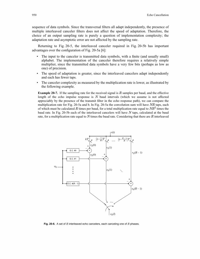
The echo replica can be generated independently for each echo channel by a set of Rinterleaved echo cancelers as shown in Fig. 20-6. Each canceler cancels the echo for onesampling phase, from among R, and has a sampling rate at the input and output equal to thebaud rate. Each canceler operates independently of the other; in particular, each generates itsown error signal for purposes of both the full-duplex data receiver and the adaptation of thecorresponding canceler.
Since the R echo channels are independent, the index l can be dropped. In the sequel weneed only consider the design of one of the interleaved echo cancelers, and all the others follownaturally. The transversal filter echo canceler generates the replica
k = cmak – m , (20.6)
where{c0, …, cN – 1}, are the N filter coefficients of one of the R interleaved transversal filters.This transversal filter generates an FIR approximation to the echo response hm(l).
Each canceler can be thought of as adapting to the impulse response of the echo channelsampled at a rate equal to the baud rate, but with a particular phase out of R possible phases.These cancelers independently converge, although they do have in common the same input
lR----
lR----
m ∞–=
∞∑
rm 0=
N 1–∑
950 Echo Cancellation
sequence of data symbols. Since the transversal filters all adapt independently, the presence ofmultiple interleaved canceler filters does not affect the speed of adaptation. Therefore, thechoice of an output sampling rate is purely a question of implementation complexity; theadaptation rate and asymptotic error are not affected by the sampling rate.
Returning to Fig. 20-5, the interleaved canceler required in Fig. 20-5b has importantadvantages over the configuration of Fig. 20-5a [6]:
• The input to the canceler is transmitted data symbols, with a finite (and usually small)alphabet. The implementation of the canceler therefore requires a relatively simplemultiplier, since the transmitted data symbols have a very few bits (perhaps as low asone) of precision.
• The speed of adaptation is greater, since the interleaved cancelers adapt independentlyand each has fewer taps.
• The canceler complexity as measured by the multiplication rate is lower, as illustrated bythe following example.
Example 20-7. If the sampling rate for the received signal is R samples per baud, and the effectivelength of the echo impulse response is N baud intervals (which we assume is not affectedappreciably by the presence of the transmit filter in the echo response path), we can compare themultiplication rate for Fig. 20-5a and b. In Fig. 20-5a the convolution sum will have NR taps, eachof which must be calculated R times per baud, for a total multiplication rate equal to NR2 times thebaud rate. In Fig. 20-5b each of the interleaved cancelers will have N taps, calculated at the baudrate, for a multiplication rate equal to N times the baud rate. Considering that there are R interleaved
Fig. 20-6. A set of R interleaved echo cancelers, each canceling one of R phases.
ek(l)
kT
r(t)
ak
ek(R – 1)
ek(1)
ek(0)rk(R – 1)
rk(1)rk(0)
+ –
–+
–+
E.C. #0
E.C. #(R - 1)
E.C. #1 +
+
+
…
k lR----+
T k R 1–R
-------------+ T…
…
PASSBAND CHANNEL 951
cancelers, the total multiplication rate is NR times the baud rate. The interleaved canceler thereforehas a multiplication rate lower by a factor of R.
For all these reasons, the configuration of Fig. 20-5b is generally preferred over Fig. 20-5a.
20 .3 . PASSBAND CHANNEL
The passband echo canceler is considerably different from the baseband channel case.Assuming the data symbols are applied directly to the canceler as in Fig. 20-5b, there are twoobvious differences:
• The canceler input is complex-valued.
• The transmitter modulator is included in the transmit path, so that the echo path is time-varying. An adaptive filter could in principle model track this time varying channel, butin practice the required adaptation speed could not be achieved.
Fortunately, the carrier frequency and phase is precisely known, so that we can compensate forthe carrier by adding a similar modulator to the transversal filter. There are numerousconfigurations possible, as we will see in this section. Pioneering work on the passband channelcanceler was done by S. Weinstein of Bell Laboratories [7]. We begin by developing a modelfor the echo path.
20.3.1. Echo Path Model
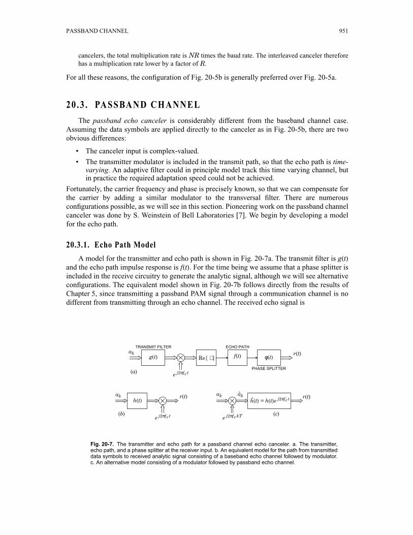
A model for the transmitter and echo path is shown in Fig. 20-7a. The transmit filter is g(t)and the echo path impulse response is f(t). For the time being we assume that a phase splitter isincluded in the receive circuitry to generate the analytic signal, although we will see alternativeconfigurations. The equivalent model shown in Fig. 20-7b follows directly from the results ofChapter 5, since transmitting a passband PAM signal through a communication channel is nodifferent from transmitting through an echo channel. The received echo signal is
Fig. 20-7. The transmitter and echo path for a passband channel echo canceler. a. The transmitter,echo path, and a phase splitter at the receiver input. b. An equivalent model for the path from transmitteddata symbols to received analytic signal consisting of a baseband echo channel followed by modulator.c. An alternative model consisting of a modulator followed by passband echo channel.
h(t) = h(t)e j2πfc t
φ(t)g(t)
(c)(b)
(a)
h(t)
e j2πfckT
r(t)r(t) akak
e j2πfc t
r(t)
e j2πfc t
ak
PHASE SPLITTER
TRANSMIT FILTER
f(t)Re{ ⋅ }
ECHO PATH
˜ak
952 Echo Cancellation
r(t) = Re akh(t – kT)e j2πfct , (20.7)
where the equivalent baseband complex-valued response is (see Section 2.4),
h(t) = (f(t)e –j2πfct) ∗ g(t) , H(f ) = F(f + fc)G(f ) . (20.8)
The conclusion is that the echo channel output can be considered as a signal of the same formas the transmitted signal, except the transmitted baseband pulse g(t) has been replaced by anecho-channel equivalent baseband output pulse h(t). The latter is obtained by shifting the echotransfer function in the vicinity of the carrier frequency down to d.c. Since h(t) is in generalcomplex-valued, even though the transmit pulse g(t) is real-valued, the echo canceler must havecomplex-valued tap coefficients! This of course implies that there is crosstalk between the in-phase and quadrature channels when they pass through the echo channel, similarly to thesituation in channel equalization.
After a minor manipulation, the analytic signal corresponding to (20.7) at the output of aphase splitter can be written in the form
r(t) = ∑k ake j2πfckTh(t – kT)e j2πfc(t – kT) = ∑k k (t – kT) (20.9)
where
(t) = h(t)e j2πfct (20.10)
is an equivalent passband pulse waveform and
k = ake j2πfckT (20.11)
is called the rotated data symbol since it is simply rotated by angle 2πfckT radians. This resultsin the model of Fig. 20-7c. The rotation of the data symbols is in effect a modulation up topassband, and then the rotated symbols are put through an equivalent passband channel withimpulse response (t). Since h(t) is a baseband pulse, this filter has a response centered at thecarrier frequency. The rotation of the data symbols is simple to implement when the carrierfrequency and baud rate have a simple relationship.
Example 20-8. For a V.32 modem, the carrier frequency is 1800 Hz and the baud rate is 2400 Hz.Therefore,
2πfcT = = radians. (20.12)
For this case, the exponent 2πfckT assumes only multiples of π ⁄ 2, and hence the rotation requiresonly multiplication by values that are of the form ±1 or ±j. The rotation in this case is always bysome multiple of 90 degrees.
2k ∞–=
∞∑
k ∞–=
∞∑
a h
h
a
h
2π18002400------------- 3π
2------
PASSBAND CHANNEL 953
20.3.2. Interleaved Passband Channel Echo Cancelers
Just as in the baseband case, the sampling rate at the receiver input will generally be amultiple R of the baud rate, necessitating interleaved echo cancelers. Defining ri(l), hi(l), and
i(l) as in (20.3) and (20.4), a relation similar to (20.5) is obtained. For the echo channel modelof Fig. 20-7b, we get
rk(l) = ∑m amhk –m(l) e j2πfc(k + l ⁄ R)T, (20.13)
and for the echo channel model of Fig. 20-7c we get
rk(l) = ∑m m k – m(l) . (20.14)
In both cases we can implement the canceler as R independent interleaved cancelers.
20.3.3. Passband vs. Baseband Transversal Filters
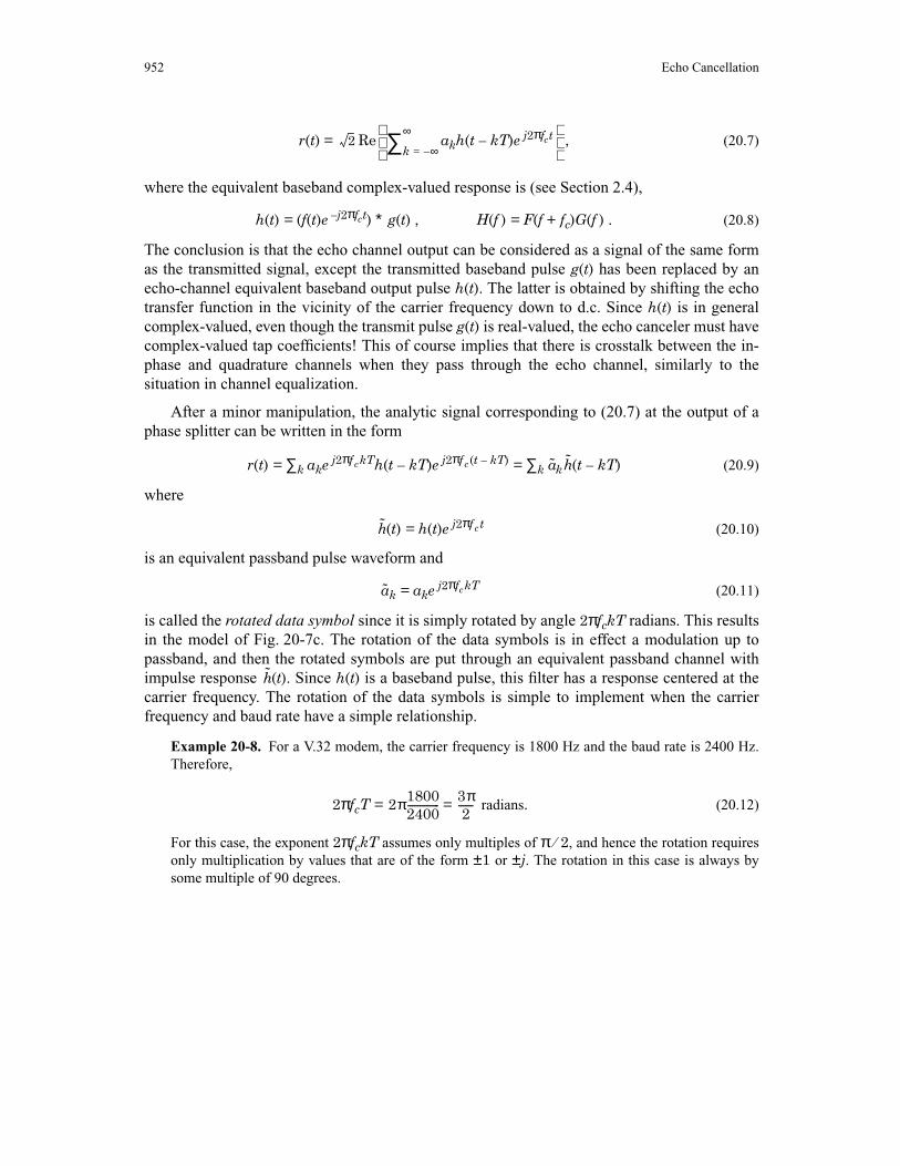
Based on the discrete-time interleaved representations for the echo channel represented by(20.13) and (20.14), there are two echo canceler configurations to synthesize these echoresponses as pictured in Fig. 20-8. The difference between these two configurations is theplacement of the modulator after or before the complex-coefficient transversal filter.
The baseband transversal filter of Fig. 20-8a follows directly from the representation ofFig. 20-7b and (20.13). Let the transversal filter have N complex-valued coefficients {c0, …,cN – 1}, in which case the echo canceler can be represented mathematically as
k(l) = cmak – m e j2πfc(k + l ⁄ R)T . (20.15)
This can be represented as a transversal filter, which performs the convolution sum, followedby a modulator. The transversal filter is approximating the equivalent baseband pulse h(t) in themodel of Fig. 20-7b, and hence we call it a baseband transversal filter.
An equivalent configuration follows from the model of Fig. 20-7c and (20.14), from whichwe get an echo canceler of the form
k(l) = cm k – m . (20.16)
This configuration is shown in Fig. 20-8b. The rotator first modulates the data symbols topassband, and the transversal filter then approximates the passband response (t) = h(t)e j2πfct.For this reason we call this a passband transversal filter.
h
a h
Fig. 20-8. Two configurations for one interleaved echo canceler corresponding to a passband channel.a. A baseband transversal filter followed by modulator. b. A modulator followed by a passbandtransversal filter.
e j2πfc(k + l ⁄ R)T
TRANSVERSALrk(l)rk(l) akak
e j2πfckT(a) (b)
FILTERTRANSVERSAL
FILTER
rm 0=
N 1–∑
rm 0=
N 1–∑ a
h
954 Echo Cancellation
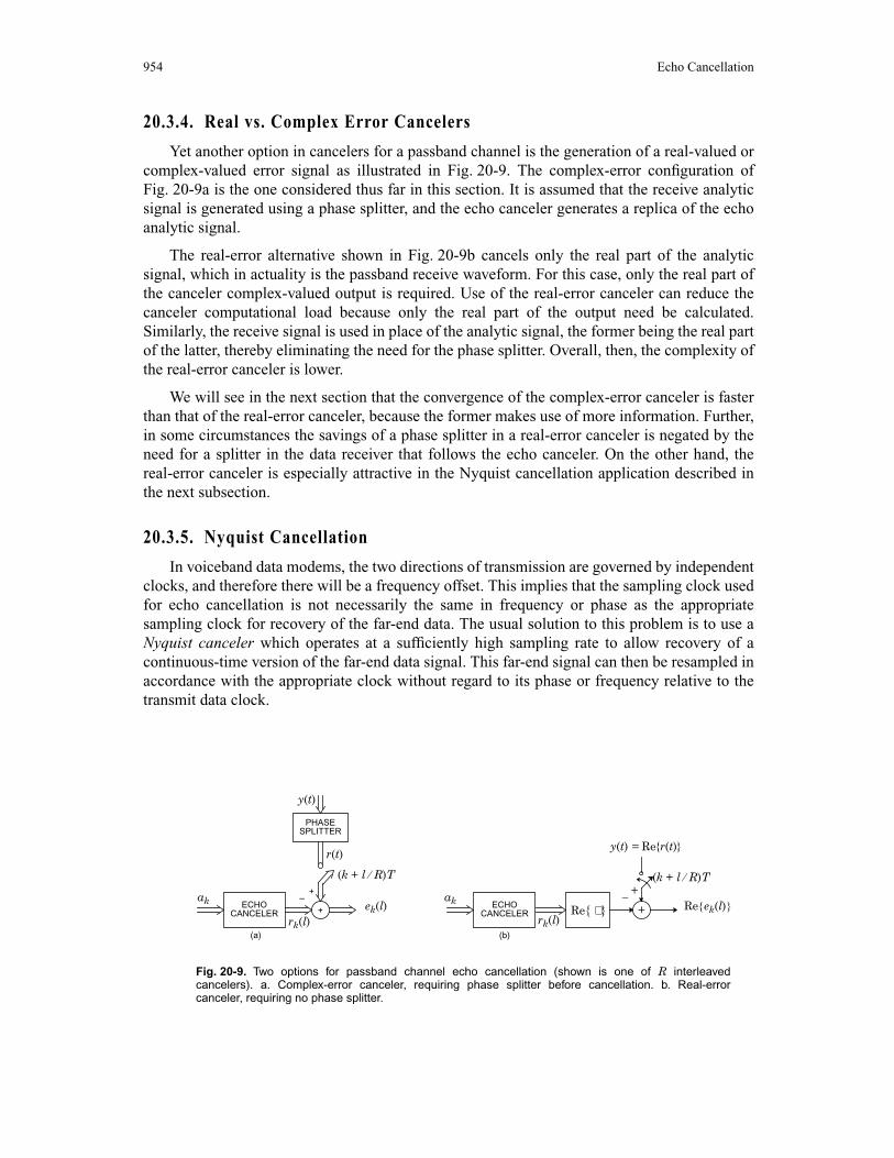
20.3.4. Real vs. Complex Error Cancelers
Yet another option in cancelers for a passband channel is the generation of a real-valued orcomplex-valued error signal as illustrated in Fig. 20-9. The complex-error configuration ofFig. 20-9a is the one considered thus far in this section. It is assumed that the receive analyticsignal is generated using a phase splitter, and the echo canceler generates a replica of the echoanalytic signal.
The real-error alternative shown in Fig. 20-9b cancels only the real part of the analyticsignal, which in actuality is the passband receive waveform. For this case, only the real part ofthe canceler complex-valued output is required. Use of the real-error canceler can reduce thecanceler computational load because only the real part of the output need be calculated.Similarly, the receive signal is used in place of the analytic signal, the former being the real partof the latter, thereby eliminating the need for the phase splitter. Overall, then, the complexity ofthe real-error canceler is lower.
We will see in the next section that the convergence of the complex-error canceler is fasterthan that of the real-error canceler, because the former makes use of more information. Further,in some circumstances the savings of a phase splitter in a real-error canceler is negated by theneed for a splitter in the data receiver that follows the echo canceler. On the other hand, thereal-error canceler is especially attractive in the Nyquist cancellation application described inthe next subsection.
20.3.5. Nyquist Cancellation
In voiceband data modems, the two directions of transmission are governed by independentclocks, and therefore there will be a frequency offset. This implies that the sampling clock usedfor echo cancellation is not necessarily the same in frequency or phase as the appropriatesampling clock for recovery of the far-end data. The usual solution to this problem is to use aNyquist canceler which operates at a sufficiently high sampling rate to allow recovery of acontinuous-time version of the far-end data signal. This far-end signal can then be resampled inaccordance with the appropriate clock without regard to its phase or frequency relative to thetransmit data clock.
Fig. 20-9. Two options for passband channel echo cancellation (shown is one of R interleavedcancelers). a. Complex-error canceler, requiring phase splitter before cancellation. b. Real-errorcanceler, requiring no phase splitter.
(k + l ⁄ R)T(k + l ⁄ R)T
– +ak ak
PHASE
Re{ ⋅ }
y(t)
r(t)
+ –
ek(l)
y(t) = Re{r(t)}
Re{ek(l)}rk(l)
(a) (b)rk(l)
SPLITTER
ECHOCANCELER
ECHOCANCELER+ +

ADAPTATION 955
The Nyquist canceler is shown in Fig. 20-10. The canceler works on samples generatedsynchronously with the transmit data stream (the dashed line indicates the source of the clockfor each sampler). The bandpass filter (BPF) prior to the sampler eliminates all noise out-of-band of the received data signal (and incidently some of the echo as well). The sampling rate ischosen to be Nyquist; that is, greater than twice the highest frequency in the receive data signal.For convenience it will be an integral multiple of the transmit baud rate clock.
After recovery of the receive data signal without the echo, a continuous-time receive signalis recovered using a lowpass filter (LPF). This signal is then resampled synchronously with thereceive data signal using a clock provided by the receiver.
An advantage of the Nyquist canceler is that an existing half-duplex data receiver can beused without modification. The purpose of the echo cancellation “front-end” is merely toeliminate the undesired echo interference from the transmitter. Note also that a real-errorcanceler has been used and is attractive in this configuration, since there is a savings of a phasesplitter. Only one phase splitter is required, the one in the receiver.
20 .4 . ADAPTATION
As with adaptive equalizers (Chapter 9), there are two measures of performance of anadaptive echo canceler: the speed of adaptation and the accuracy of the cancellation afteradaptation. There is a tradeoff between these two measures: for a particular class of adaptationalgorithm, as the speed of adaptation is increased the accuracy of the transfer function afteradaptation gets poorer. This tradeoff is fundamental, since a longer averaging time is necessaryto increase asymptotic accuracy, but slows the rate of convergence. Usually the motivation foradapting an echo canceler is that the transfer function of the echo is not known in advance. It isalso probable that the echo transfer function is changing with time, although in most cases thechange will be quite slow (say in response to changes in the temperature of the transmissionfacilities). Thus, in most instances the accuracy of the final cancellation of the echo is the mostcritical design factor.
Example 20-9. In the digital subscriber loop, the transceiver will often be dedicated to a particularloop. As long as the transceiver is allowed to run all the time, or at least stores the echo cancelercoefficients between calls, the adaptation can be quite slow (resulting in a high accuracy) because
Fig. 20-10. A Nyquist echo canceler operating synchronously with the transmitted data stream andasynchronously from the data receiver.
ak
HYBRID
BPFLPFRECEIVER
NYQUIST
–+
2-WIRELINE
TRANSMITTER
ECHOCANCELER
+
956 Echo Cancellation
the echo path transfer function should change only in response to temperative changes and similarinfluences, which occur quite slowly.
Although the ability of the canceler to rapidly track a changing echo response is usually notimportant, the speed of initial adaptation from an arbitrary initial condition is often important.
Example 20-10. In a voiceband data modem, the echo canceler must converge anew at thebeginning of each call. The adaptation of the echo canceler is therefore a part of the initializationsequence before useful data transmission can occur. Since one would like to minimize thatinitialization time, there is motivation to adapt as quickly as possible. This is a natural applicationfor a gear-shifting algorithm, since the accuracy of cancellation is not critical during the trainingperiod (no actual data transmission is taking place) and therefore it is permissible to start with alarger step-size. With respect to the the far-end echo canceler (Section 20.6) a more rapid trackingcapability will be required.
We will derive a SG adaptation algorithm for the complex-error passband transversal filteralgorithm in this section [8]. The case of a baseband channel canceler is a special case[9][10][11] and will also be covered. The adaptation of the baseband transversal filter cancelerfor the passband channel is a simple extension and is relegated to the problems [7]. Theadaptation of the real-error canceler is a bit more complicated to derive and analyze and isrelegated to Appendix 20-A. More general results on adaptation algorithms and theirconvergence can be found in [12].
As usual, we consider the minimum MSE problem first, followed by the SG algorithm. Inall cases we will derive the adaptation algorithm for only one of the R interleaved cancelers,and assume that same algorithm is applied identically to all.
20.4.1. Minimum MSE Solution
In this section we consider the optimum tap coefficients for a complex-error passbandtransversal filter canceler. Write the m-th filter coefficient as cm and the analytic echocancellation error at time k as Ek. Define a notation for the vector of N filter coefficients
c = [c0, c1 , …, cN – 1]′. (20.17)
For the passband transversal filter canceler, the input to the transversal filter is the rotated datasymbol Ãk. Define a vector of the current and N –1 past input rotated data symbols
k = [Ãk, Ãk – 1,…, Ãk – N + 1]. (20.18)
If the impulse response of the echo channel is k(l), 0 ≤ k < ∞ for the l-th interleaved canceler,then it is also convenient to define a vector of the first N of these impulse response samples,
= [ 0, , …, N – 1]′ , (20.19)
where in this and subsequent equations the “l” is suppressed. All of these quantities arecomplex-valued, except in the baseband channel case where they are real-valued.
With this notation in hand, the analytic error signal can be written as
Ek = mÃk – m – cmÃk – m + Xk
a
h
h h h h
hm 0=
∞∑ m 0=
N 1–∑
ADAPTATION 957
= ( – c)′ k + Vk , (20.20)
where Xk is the far-end data signal plus noise and
Vk = mÃk – m + Xk (20.21)
is the residual uncancelable echo. This uncancelable echo has several components:
• Echo components with delays that exceed the number of coefficients in the transversalfilter,
• The noise introduced on the channel from the far-end data transmitter, and
• The far-end data signal, which represents a noise with respect to the adaptation of theecho canceler.
For the MSE solution, we assume that Ãk is a wide-sense stationary discrete-time randomprocess and that the echo channel k is known. We want to minimize the MSE error E(|Ek|2).This error signal includes, as one component, the far-end data signal, which we don’t wish tominimize. Fortunately, the echo canceler has no influence over this data signal. As long as thedata signals in the two directions are uncorrelated, minimizing the MSE will be the same asminimizing the component of echo in the error signal (as we will see).
Following consistent notation to Section 9.2, define
p = E[Vk k] , Φ = E[ k′ ] , (20.22)
where these quantities are independent of k due to the wide-sense stationarity assumption. Theautocorrelation of the rotated data symbols is easily related to the autocorrelation of the datasymbols itself.
Exercise 20-1. Show that the relationship between the rotated and non-rotated data symbolautocorrelation functions is,
E[ÃkÃk* ] = e j2πfc(k – m)T E[AkAm* ] . (20.23)
This demonstrates that if the data symbols are wide-sense stationary, then so too are the rotatedsymbols, where the relationship between the power spectra is
(e j2πfT ) = Sa(e j2π(f – fc)T). (20.24)
A simplification of the analysis of the echo canceler relative to the adaptive equalizer is that canwe generally assume that the successive input data symbols are uncorrelated. This implies thatthe power spectrum is white, and from (20.24) the rotated data symbols are white also. Inaddition, since |Ã|=|Ak| the rotated symbols have the same variance as the symbolsthemselves. It follows for this case that the autocorrelation matrix Φ is diagonal,
Φ = I, = E[|Ak|2] . (20.25)
Explicitly evaluating the mean-square error,
E[|Ek|2] = ( – c)* ′Φ( – c) – 2Re{( – c)*′p} + σv2 , (20.26)
h a
hm N=
∞∑
h
a ak∗a
Sa
σa2 σa
2
h h h

958 Echo Cancellation
where σv2 = E[|Vk|2] is the variance of the uncancelable echo. This is a Hermitian form in
the tap weight vector c, and hence there is a unique minimum. (20.26) can be written in theform
E[|Ek|2] = ξmin + (c – copt)*′Φ(c – copt) (20.27)
where
copt = + Φ –1p , ξmin = σv2 – p*′Φ –1p . (20.28)
Example 20-11. For the autocorrelation of (20.25), this solution reduces to
copt = + p , ξmin = σv2 – || p ||2 . (20.29)
The Φ matrix is Hermitian and non-negative definite, and has non-negative real-valued eigenvalues.
For the optimal solution to be unique, we have to assume Φ is positive-definite, implying itis invertible, in which case this inverse Φ –1 is also a Hermitian matrix. In this event, the secondterm in (20.27) is non-negative and has a unique minimum c = copt. This choice also minimizesthe mean-square error, with resultant minimum value E[|Ek|2] = ξmin.
Example 20-12. If the data symbols are uncorrelated with the uncancelable error, or p = 0, then theoptimum tap weight vector is equal to the echo impulse response copt = and the resultant mean-square error is equal to the variance of the uncancelable echo, ξmin = σv
2. The optimum coefficientvector and resulting MSE are independent of the autocorrelation matrix Φ. This condition will holdwhen the far-end data signal Xk is uncorrelated with the near-end data symbols. When that conditionis violated, the optimum coefficient vector is not equal to the echo impulse response. This imposes asystem requirement for proper operation that the data symbols in the two directions be uncorrelated.If this is violated, the echo cancellation adaptation will be biased away from replicating the echoimpulse response.
20.4.2. Stochastic Gradient (SG) Algorithm
As with adaptive equalization, the most widely used adaptation algorithm for the echocanceler is the stochastic gradient (SG) algorithm. This is very similar to the algorithm wederived for adaptive equalizers in Chapter 9.
Consider the passband transversal filter case. The first step is to determine the magnitude-squared of the analytic cancellation error as a function of the coefficient vector c,
|Ek|2 = |Rk – c′ k|2 = |Rk|2 – 2Re{c*′Rk k*} +c*′ k′ c (20.30)
and then we take the gradient of this expression with respect to c. In view of Exercise 9-5 andthe fact that the matrix k′ is Hermitian, we get
∇c|Ek|2 = 2 k′c – 2Rk k* = –2Ek k* . (20.31)
The SG algorithm follows from evaluating this gradient at the last coefficient vector,multiplying by step-size β ⁄ 2, and subtracting the result from the last coefficient vector to getthe new coefficient vector,
h
h 1σa
2------ 1
σa2
------
h
a a ak∗a
ak∗a
ak∗a a a
ADAPTATION 959
ck = ck – 1 + βEk k* , (20.32)
Ek = Rk – ck – 1′ k . (20.33)
The implementation of this algorithm is very similar to the adaptive equalizer case ofChapter 9, with one important difference; namely, the input samples k are the rotatedtransmit data symbols, and are typically drawn from a relatively small alphabet. This cansimplify the implementation of the multiplications in both the convolution sum and theadaptation algorithm. The baseband channel case follows as a special case, where all quantitiesare real-valued and fc = 0. The derivation of SG adaptation algorithms for other cancelerstructures of interest is relegated to exercises.
Exercise 20-2. Show that the stochastic gradient adaptation algorithm for the complex-errorcanceler with baseband transversal filter is
ck = ck – 1 + βe j2πfc(k + l ⁄ R)T Ekak* (20.34)
Ek = Rk – e j2πfc(k + l ⁄ R)Tck–1′ ak . (20.35)
Hint: See the hint for Problem 20-6.
Exercise 20-3. Show that the stochastic gradient adaptation algorithm for the real-error cancelerwith passband transversal filter is
ck = ck – 1 + βRe{Ek}ak* , (20.36)
Re{Ek} = Re{Rk} – Re{ck–1′ ak } . (20.37)
In the remainder of this section we will consider the convergence properties of theadaptation algorithm. Since the convergence analysis is so similar to the adaptive equalizationcase of Chapter 9, we can draw many results from there.
20.4.3. Convergence of the SG Algorithm
Defining a coefficient error vector
qk = ck – copt , (20.38)
the first step is to derive a stochastic difference equation for this error vector.
Exercise 20-4. Define a stochastic matrix
Γk = I –β k′ (20.39)
and define the error of the optimal fixed coefficient echo canceler,
Dk = Rk – copt′ k. (20.40)
Then show that the coefficient error vector is governed by the stochastic difference equation
qk = Γkqk – 1 + βDkak* . (20.41)
We can also determine the excess MSE of the canceler directly from (20.27),
a
a
A
ak∗a
a
960 Echo Cancellation
E[|Ek|2] = ξmin + E[qk*′Φqk] . (20.42)
These results are identical to the stochastic difference equation derived for the adaptiveequalizer of Chapter 9, with minor changes in notation reflecting the different application, andso we can use the results derived there directly in analyzing the echo canceler.
In particular, for the case of uncorrelated data symbols of (20.25), (20.42) becomes
E[|Ek|2] = ξmin + E[|| qk ||2] , (20.43)
where the expected vector norm approximately obeys the difference equation
E[||| qk+1 ||2] = γ ⋅ E[|| qk ||2] + β2 ξmin , (20.44)
γ = 1 – 2β + β2Nσa4 . (20.45)
The time constant of convergence of MSE can be obtained from setting γτ = 1 ⁄ e, from whichwe get
τ ≈ . (20.46)
The maximum convergence rate for excess MSE is reached at
βopt = , (20.47)
with a resulting time constant
τ ≈ N ⁄ 2. (20.48)
The asymptotic excess MSE from (20.44) is
E[|| qk ||2] → ξmin , (20.49)
and at the optimum step-size (optimum in terms of rate of convergence of MSE, not theasymptotic MSE), the asymptotic error is
E[|| qk ||2] → ξmin. (20.50)
In view of (9.66), the asymptotic MSE is
E[|Ek|2] → ξmin + ξmin = 2ξmin . (20.51)
Thus, for the fastest convergence, the total MSE is twice the minimum MSE for a fixedcoefficient filter, with half that MSE attributable to the asymptotic wandering of the filtercoefficients about their optimum value.
Example 20-13. Continuing Example 20-12, since ξmin is the variance of the uncancelable errorfor this case, the asymptotic MSE is for this case
E[|Ek|2] → 2σv2. (20.52)
σa2
σa2
σa2
12βσa
2--------------
1N σa
2------------
Nβ2 Nβσa
2–-------------------------
1σa
2------
FAR-END ECHO 961
Since (hopefully) the dominant component of the uncancelable error is the far-end data signal, thisimplies that for the choice of the optimum step-size the SNR, defined as the ratio of the far-end datasignal power to excess MSE for cancellation, will be 0 dB. In words, the residual echo will have thesame power as the received signal. This is, of course, not practical, so a smaller step-size resulting inslower convergence will be required.
The analysis of convergence applies equally well to the baseband channel case, virtuallywithout modification. The baseband transversal filter canceler analysis is also straightforwardbased on the results so far (Problem 20-7). The real-error canceler is a bit more complicated,and hence is relegated to Appendix 20-A. The results there can be summarized succinctly asfollows. For the same step-size, the real-error canceler converges with a time constant that isapproximately twice as great as the complex-error canceler. In retrospect, this is not surprisingsince the real-error canceler is in effect throwing away half the information available (theimaginary part of the analytic error). Both cancelers have approximately the same asymptoticMSE. Thus, we must trade off the (in some circumstances) simpler implementation of the real-error canceler against its poorer convergence properties.
20 .5 . FAR-END ECHO
In the voiceband data modem, echo can occur not only at the near-end in conjunction withthe four-wire to two-wire converter, but also at intermediate points in the telephone network.These echos are generally more attenuated than the near-end echo, and hence require a lessaccurate cancellation, but they are also subject to additional impairments such as jitter andfrequency offset. Hence, very accurate cancellation of these echos requires the addition ofalgorithms to the basic echo canceler considered thus far.
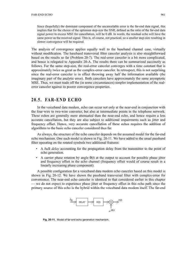
As always, the structure of the echo canceler depends on the assumed model for the far-endecho mechanism. One such model is shown in Fig. 20-11. We have added to the usual passbandfilter operating on the rotated symbols two additional features:
• A bulk delay accounting for the propagation delay from the transmitter to the point ofecho generation.
• A carrier phase rotation by angle θ(t) at the output to account for possible phase jitterand frequency offset in the echo channel (frequency offset would of course result in alinearly increasing phase component).
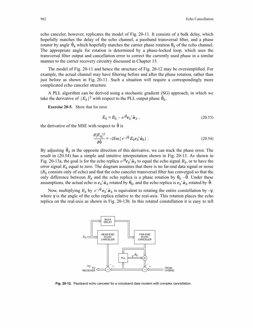
A possible configuration for a voiceband data modem echo canceler based on this model isshown in Fig. 20-12. We have shown the passband transversal filter with complex-error forconvenience. The near-end echo canceler is identical to that considered earlier in this chapter— we do not expect to experience phase jitter or frequency offset in this echo path since theprimary source of this echo is the hybrid within the voiceband data modem itself. The far-end
Fig. 20-11. Model of far-end echo generation mechanism.
akDELAY h(t)
e jθ(t)
r(t)˜
962 Echo Cancellation
echo canceler, however, replicates the model of Fig. 20-11. It consists of a bulk delay, whichhopefully matches the delay of the echo channel, a passband transversal filter, and a phaserotator by angle k which hopefully matches the carrier phase rotation θk of the echo channel.The appropriate angle for rotation is determined by a phase-locked loop, which uses thetransversal filter output and cancellation error to correct the currently used phase in a similarmanner to the carrier recovery circuitry discussed in Chapter 15.
The model of Fig. 20-11 and hence the structure of Fig. 20-12 may be oversimplified. Forexample, the actual channel may have filtering before and after the phase rotation, rather thanjust before as shown in Fig. 20-11. Such a situation will require a correspondingly morecomplicated echo canceler structure.
A PLL algorithm can be derived using a stochastic gradient (SG) approach, in which wetake the derivative of |Ek|2 with respect to the PLL output phase k.
Exercise 20-5. Show that for error
Ek = Rk – ck′ k , (20.53)
the derivative of the MSE with respect to is
= –2Im{ Ekck′ k} . (20.54)
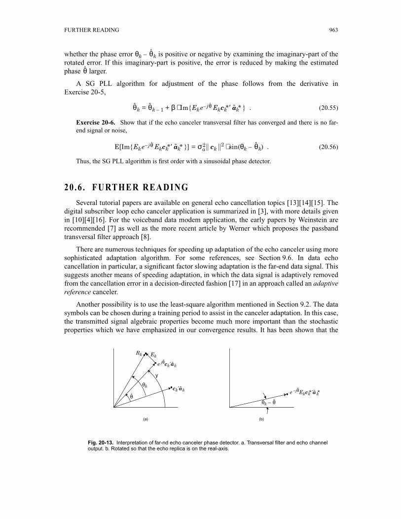
By adjusting k in the opposite direction of this derivative, we can track the phase error. Theresult in (20.54) has a simple and intuitive interpretation shown in Fig. 20-13. As shown inFig. 20-13a, the goal is for the echo replica ck′ k to equal the echo signal Rk, or to have theerror signal Ek equal to zero. The diagram assumes that there is no far-end data signal or noise(Rk consists only of echo) and that the echo canceler transversal filter has converged so that theonly difference between Rk and the echo replica is a phase rotation by θk – . Under theseassumptions, the actual echo is ck′ k rotated by θk, and the echo replica is ck′ k rotated by .
Now, multiplying Ek by ck′ k is equivalent to rotating the entire constellation by –γ,where γ is the angle of the echo replica relative to the real-axis. This rotation places the echoreplica on the real-axis as shown in Fig. 20-13b. In this rotated constellation it is easy to tell
Fig. 20-12. Passband echo canceler for a voiceband data modem with complex cancellation.
ak
–+ +
–
e jθk
FROMTOTO
PLL
BULK
NEAR-END FAR-END˜
ˆ
++
DELAY
ECHOCANCELER
ECHOCANCELER
RECEIVER HYBRID
θ
θ
e jθ a
θ
∂ Ek2
∂θ---------------- e j– θ a
θ
e jθ a
θa a θ
e jθ– a
FURTHER READING 963
whether the phase error θk – k is positive or negative by examining the imaginary-part of therotated error. If this imaginary-part is positive, the error is reduced by making the estimatedphase larger.
A SG PLL algorithm for adjustment of the phase follows from the derivative inExercise 20-5,
k = k – 1 + β ⋅ Im{Ek Ekck*′ k* } . (20.55)
Exercise 20-6. Show that if the echo canceler transversal filter has converged and there is no far-end signal or noise,
E[Im{Ek Ekck*′ k* }] = || ck ||2 ⋅ sin(θk – k) . (20.56)
Thus, the SG PLL algorithm is first order with a sinusoidal phase detector.
20 .6 . FURTHER READING
Several tutorial papers are available on general echo cancellation topics [13][14][15]. Thedigital subscriber loop echo canceler application is summarized in [3], with more details givenin [10][4][16]. For the voiceband data modem application, the early papers by Weinstein arerecommended [7] as well as the more recent article by Werner which proposes the passbandtransversal filter approach [8].
There are numerous techniques for speeding up adaptation of the echo canceler using moresophisticated adaptation algorithm. For some references, see Section 9.6. In data echocancellation in particular, a significant factor slowing adaptation is the far-end data signal. Thissuggests another means of speeding adaptation, in which the data signal is adaptively removedfrom the cancellation error in a decision-directed fashion [17] in an approach called an adaptivereference canceler.
Another possibility is to use the least-square algorithm mentioned in Section 9.2. The datasymbols can be chosen during a training period to assist in the canceler adaptation. In this case,the transmitted signal algebraic properties become much more important than the stochasticproperties which we have emphasized in our convergence results. It has been shown that the
Fig. 20-13. Interpretation of far-nd echo canceler phase detector. a. Transversal filter and echo channeloutput. b. Rotated so that the echo replica is on the real-axis.
(b)(a)
γ
θk
EkRk
θθk – θ
e jθck akˆ ˜
e –jθEkck*´ak*ˆ ˜
ck ak˜
θ
θ
θ θ e j– θ a
e j– θ a σa2 θ
964 Echo Cancellation
mean values of the filter coefficients of a canceler based on least-squares can converge in Ndata symbols for an N-tap canceler [18]. Furthermore, it has been shown that the least-squaresalgorithm can be virtually as simple as the stochastic gradient algorithm for a reference signalwhich is chosen to be a pseudo-random sequence [19]. This sequence is also particularlysimple to generate during a training period.
The implementation of a data echo canceler in monolithic form represents specialchallenges because of the high accuracy required. This is discussed in more depth in [10][4].
Some older work in speech cancelers and some more recent work in data cancelers hasextended the adaptive echo canceler technique to nonlinear echo generation phenomena[20][21]. In data transmission, the objectives for degree of cancellation are sufficientlyambitious that nonlinear echo generation phenomena are of importance [10][21][4].
Appendix 20-A.Real-Error Canceler Convergence
In this appendix we analyze the convergence of the real error canceler for a passband channeland passband transversal filter. In general we will find that we must make stronger assumptionsfor this case to get simple results than we made in the complex error case. Specifically, we oftenhave to assume independence of random variables whereas in the complex error caseuncorrelated random variables will suffice.
We can find the minimum MSE solution for the real error canceler most easily by using thegradient formula derived in Exercise 20-3,
∇c(Re{Ek}) = –2Re{Ek} k* . (20.57)
Equating the expected value with the zero vector will give us the optimum coefficient vector.The evaluation of this expected value is aided by the following result:
Exercise 20-7. Given a sequence of transmitted rotated data symbol which are mutuallyindependent, and for which the real and imaginary parts are zero-mean, identically distributed, andindependent, show that
E[ k k′] = 0 . (20.58)
Similarly, for the same assumptions on the uncancelable error Vk, show that
E[Vk2] = 0 . (20.59)
Lest this latter result seem strange, remember that Vk is complex valued, and hence its variance isE[|Vk|2], not E[Vk
2].
Using this result and taking the expected value of (20.57), we get immediately
Φ( – c) + p + q = 0 , (20.60)
a
a a
h
FURTHER READING 965
where Φ and p are defined as before and
q = E[Vk* k*] . (20.61)
It follows that the optimum coefficient vector is
copt = + Φ –1(p + q) , (20.62)
which is almost the same as for the complex error case with the addition of the q term. In fact,for the important case where the uncancelable error is independent of the transmitted datasymbols and both are zero-mean, (20.62) reduces to copt = and the solution is the same as forthe complex error case.
The real error SG algorithm is given by (20.36). We can easily develop a stochasticdifference equation governing the trajectory of the coefficient vector error.
Exercise 20-8. In analogy to Exercise 20-4, show that for the real error algorithm we get a slightlymore complicated result
qk = Γkqk –1 – Λkqk –1* + βRe{Dk} k* (20.63)
where the stochastic matrices are
Γk = I – β k, Λk = β k∗′ . (20.64)
Fortunately, under reasonable assumptions the three terms in (20.63) are independent. First,from the orthogonality principle that the real error for the minimum MSE canceler Re{Dk} isuncorrelated with the sequence of transmitted data symbols,
E[Re{Dk} k*] = 0 . (20.65)
If we further assume that Dk is independent of the transmitted data symbols, and zero-mean,then the expected value of any cross terms between Re{Dk} and Γk or Λk will be zero. Further,Γk and Λk are themselves uncorrelated.
Exercise 20-9. Using the results of Exercise 20-7, show that
E[ΓkΛk*] = 0 . (20.66)
Now we are prepared to determine the expected value of || qk ||2, using in part the results ofAppendix 9-A. From that appendix (recall that the definition of Γk is slightly different here),
E[Γk*′Γk] = (1 – β + β2(ηa + (N – 1) )⋅I , ηa = E[|ak|4] . (20.67)
By a similar computation, we can find the second term.
Exercise 20-10. Show that approximately
E[Λk*′Λk] = β2 ⋅I . (20.68)
Finally, the expected norm-squared of (20.63) becomes the expected norm-squared of threeterms,
E[|| Γkqk – 1||2] = qk – 1*′ E[Γk*′Γk]qk – 1 = (1 – β + β2(ηa + (N – 1) ))||qk – 1||2 , (20.69)
a
h
h
a
12--- ak
∗a 12--- ak
∗a
a
σa2 1
4--- σa
4
14--- σa
4
σa2 1
4--- σa
4
966 Echo Cancellation
E[||Λkqk – 1* ||] = qk – 1′ E[Λk* ′Λk]qk–1= β2(ηa + (N – 1) ))||qk – 1||2 , (20.70)
E[||βRe{Dk} k*||2] = β2E[(Re{Dk})2]|| k||2 = N β2E[(Re{Dk})2] . (20.71)
Evaluation of this expression is aided by the following result.
Exercise 20-11.
(a) Assume that the uncancelable error Dk consists of a filtered far-end data signal plus an additivenoise. Further make the usual independence and white-noise assumptions on these twocomponents and show that
E[Dk2] = E[(Dk*)2] = 0 . (20.72)
(b) Show that
E[(Re{Dk})2]= E[|Dk|2] = ξmin . (20.73)
In other words, the real and imaginary parts of E[|Dk|2] are equal.
These results give the following difference equation for the norm-squared error vector,
E[||[qk ||2] = γE[|| qk – 1||2] + N β2ξmin , (20.74)
γ = 1 – β + β2(ηa + (N – 1) ) . (20.75)
Now we are in a position to compare the real error and complex error cancelers. Firstlooking at the asymptotic MSE, the complex error case is given by (20.49), whereas from(20.74)
E[||qk||2] → ⋅ ξmin , (20.76)
which is the same as (20.49). Similarly, calculating an approximate time constant τ from(20.75) as γτ = 1 ⁄ e, we get for small step-size
τ ≈ , (20.77)
which is twice as long as for the complex error canceler (20.46).
Problems
Problem 20-1. Consider using echo cancellation for a digital subscriber loop with AMI line coding(Section 19.1). What options are there for realization of the line coder, and where would it be mostreasonable to connect the echo canceler input?
14--- σa
4
a a σa2
12--- 1
2---
12--- σa
2
σa2 1
2--- σa
4
Nβ2 Nβσa
2–-------------------------
1βσa
2----------
FURTHER READING 967
Problem 20-2. Consider a V.32 voiceband data modem with the following parameters: baud rate2400 Hz, carrier frequency 1800 Hz, passband channel covering the band from 300 to 3000 Hz. Furtherassume that the echo response has a duration of 32 baud intervals.
(a) Assuming the receive signal is sampled at a rate equal to an integer multiple of the baud rate, whatis the most reasonable sampling rate? Discuss the considerations in the choice of this rate.
(b) For this sampling rate, compare the multiplication rate for two cancelers, one connected to thesampled transmitted waveform and the other to the transmitted data symbols.
Problem 20-3. For a passband echo canceler, it is possible to put a demodulator in the receiver prior tocancellation of the echo.
(a) Show two alternative configurations, one using a phase splitter and the other a lowpass filter.Develop an equivalent echo channel model analogous to Fig. 20-7.
(b) Is it possible or reasonable to consider a real-error canceler for this configuration?
(c) Describe the echo canceler required for this configuration.
(d) How will the adaptation rate of this configuration compare to the configurations considered inSection 20.3?
(e) Discuss the advantages and disadvantages of this configuration.
Problem 20-4. Assuming the echo response extends for N baud intervals and R interleaved cancelers,compare the complexity as measured in equivalent real-valued multiplication rates for all combinationsof a baseband and passband transversal filter with a real-error and complex-error canceler. Whichconfigurations are more attractive in accordance with this complexity metric?
Problem 20-5. How would you modify Fig. 20-10 to use a complex-error canceler? Show that only onephase splitter is required, at the expense of a second lowpass filter.
Problem 20-6. Determine the MSE solution for the complex-error canceler with baseband transversalfilter, and find the optimal coefficient vector. Hint: Show that minimizing E[|Ek|2] is equivalent tominimizing E[|e –j2πfc(k + l ⁄ R)T Ek|2], and then minimize the latter quantity.
Problem 20-7. For a passband echo channel, we can use a baseband echo canceler followed bymodulator, or a modulator (rotator) followed by passband echo canceler. Give a convincing argumentthat the convergence rate and asymptotic MSE of the baseband echo canceler is the same as theconvergence rate and MSE of the passband echo canceler.
Problem 20-8.
(a) The PLL algorithm of Exercise 20-6 will have a tracking capability somewhat dependent on theecho impulse response. Explain.
(b) How would you fix this problem?
Problem 20-9.
(a) Show that
= –2Re{Ek}Im{ ck*′ k* } . (20.78)
(b) Use this result to develop a first-order PLL algorithm that uses only the real-error. Interpret thisalgorithm graphically.
∂ Re Ek{ }( )2
∂θ-------------------------------- e j– θ a
968 Echo Cancellation
(c) Find the expected value of the phase correction term.
References
1. B. Aschrafi,P. Meschkat,andK. Szechenyi, “Field Trial of a Comparisonof Time Separation,EchoChancellation,andFour-Wire Digital SubscriberLoops,” Proceedingsof the Int. Symp.onSubscriber Loops and Services, (Sep. 1982).
2. J-O. Andersson,B. Carlquist,A. Bauer, andI. Dahlqvist,“An LSI Implementationof an ISDNEcho Canceler: Design and Network Aspects,” IEEE Journal on Selected Areas inCommunications, November 1986.
3. D. G. Messerschmitt,“Design Issuesfor the ISDN U-Interface Transceiver,” IEEE Jour. onSpecial Areas in Communications, (Nov. 1986).
4. O. Agazzi,D. A. Hodges,andD. G. Messerschmitt,“Large-ScaleIntegrationof Hybrid-MethodDigital Subscriber Loops,” IEEE Trans. on Communications, Vol. COM-30, p. 2095 (Sep. 1982).
5. J. Tzeng, D. Hodges, and D. G. Messerschmitt,“Baud Rate Timing Recovery in DigitalSubscriber Loops,” IEEE Int. Conf. on Communications, (June 1985).
6. K. H. Mueller andM. Muller, “Timing Recovery in Digital SynchronousDataReceivers,” IEEETrans. on Communications, Vol. COM-24,pp. 516-531 (May 1976).
7. S.B. Weinstein,“A PassbandData-DrivenEchoCancellerfor Full-Duplex TransmissiononTwo-Wire Circuits,” IEEE Trans. on Communications, (July 1977).
8. 7. J. J. Werner, “An Echo-Cancellation-Based4800 Bit/s Full-Duplex DDD Modem,” IEEEJournal on Selected Areas in Communications, Vol. SAC-2 (5), (Sep. 1984).
9. B. Widrow, J. McCool, M. Larimore, and C. Johnson,Jr., “Stationary and Non-StationaryLearningCharacteristicsof the LMS Adaptive Filter,” Proc. IEEE, Vol. 64 (8), pp. 1151-1162(Aug. 1976).
10. N. A. M. Verhoeckx,H. C. VanDenElzen,F. A. M. Snijders,andP. J.VanGerwen,“Digital EchoCancellationfor BasebandData Transmission,” IEEE Trans. on ASSP, Vol. ASP-26(6), (Dec.1979).
11. D. L. Duttweiler, “A Twelve-ChannelDigital EchoCanceller,” IEEE Trans. on Communications,pp. 647-653 (May 1978).
12. M. L. HonigandD. G. Messerschmitt,Adaptive Filters: Structures, Algorithms, and Applications,Kluwer Academic Publishers, Boston (1984).
13. M. SondhiandD. A. Berkley, “SilencingEchoson theTelephoneNetwork,” IEEE Proceedings,Vol. 8, (Aug. 1980).
14. D. G. Messerschmitt,“Echo Cancellationin Speechand Data Transmission,” IEEE Jour. onSelected Areas in Communications, Vol. SAC-2 (2), p. 283 (March 1984).
15. D. G. Messerschmitt,“EchoCancellationin SpeechandDataTransmission,” pp.182in AdvancedDigital Communications Systems and Signal Processing Techniques, ed.K. Feher, Prentice-Hall,Englewood Cliffs, N.J. (1987).
FURTHER READING 969
16. O. Agazzi, D. G. Messerschmitt,and D. A. Hodges,“Nonlinear Echo Cancellationof DataSignals,” IEEE Trans. on Communications, Vol. COM-30, p. 2421 (Nov. 1982).
17. D. D. Falconer, “Adaptive ReferenceEchoCancellation,” IEEE Trans. on Communications, Vol.COM-30 (9), (Sept. 1982).
18. T. L. Lim andM. S.Mueller, “Rapid EqualizerStart-UpUsingLeastSquaresAlgorithms,” Proc.International Conference on Communications, (1980).
19. J. Salz, “On the Start-UpProblemin Digital EchoCancellers,” Bell System Technical Journal,Vol. 60 (10), pp. 2345-2358 (July-Aug., 1983).
20. E. J.Thomas,“Someconsiderationson theapplicationof theVolterrarepresentationof nonlinearnetworksto adaptive echocancellers,” Bell System Technical Journal, Vol. 50 (8), pp.2797-2805(Oct. 1971).
21. N. HolteandS.Stueflotten,“A New Digital EchoCancelerfor Two-Wire SubscriberLines,” IEEETrans. on Communications, Vol. COM-29 (11), pp. 1573-1581 (Nov. 1981).

970 Echo Cancellation