2 Fluxtrol Sample Induction Heating Installations
41
© 2006 Fluxtrol, Inc. www.fluxtrol.com Chapter II. Chapter II. Induction Installations Induction Installations
-
Upload
fluxtrol-inc -
Category
Technology
-
view
8.676 -
download
2
Transcript of 2 Fluxtrol Sample Induction Heating Installations

© 2006 Fluxtrol, Inc. www.fluxtrol.com
Chapter II. Chapter II.
Induction InstallationsInduction Installations
© 2006 Fluxtrol, Inc. www.fluxtrol.com
Induction Installation StructureInduction Installation Structure
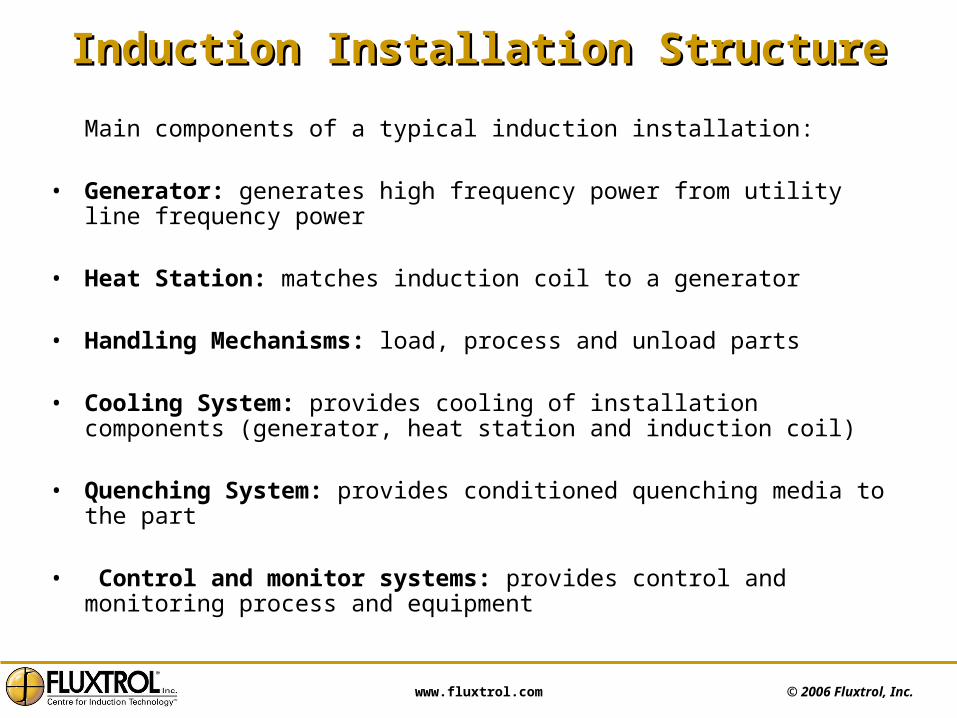
Main components of a typical induction installation:
• Generator: generates high frequency power from utility line frequency power
• Heat Station: matches induction coil to a generator
• Handling Mechanisms: load, process and unload parts
• Cooling System: provides cooling of installation components (generator, heat station and induction coil)
• Quenching System: provides conditioned quenching media to the part
• Control and monitor systems: provides control and monitoring process and equipment

© 2006 Fluxtrol, Inc. www.fluxtrol.com
Layout of Induction Hardening InstallationLayout of Induction Hardening Installation
Quenchsystem
Handling Mechanism/
Machine
Machinecontrol
Heat
station Coil
Watercoolingsystem
PowerGenerator
© 2006 Fluxtrol, Inc. www.fluxtrol.com
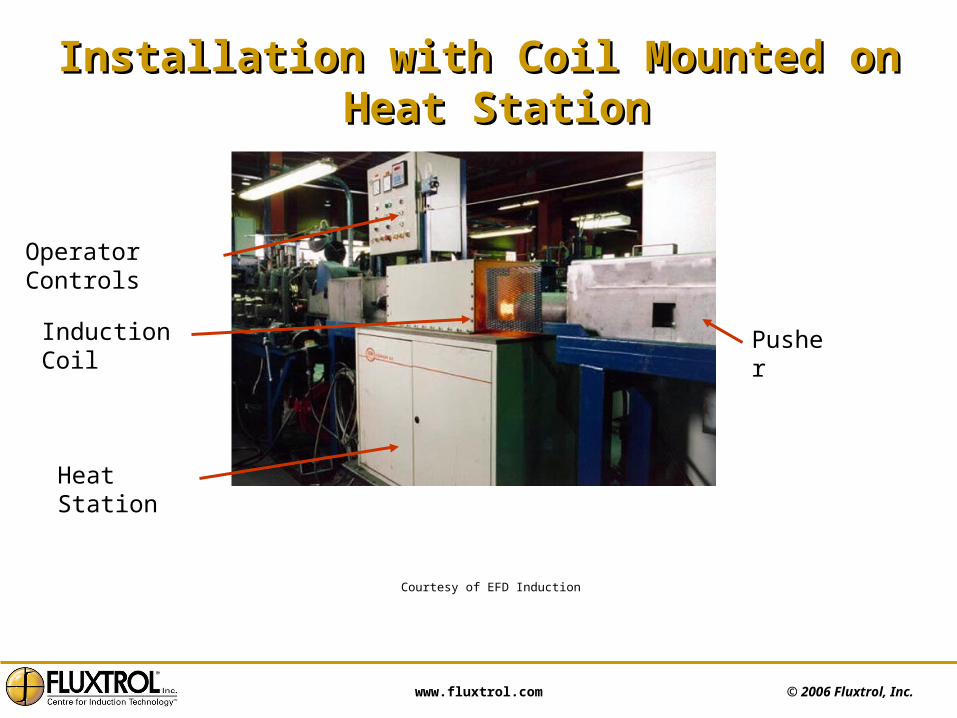
Installation with Coil Mounted on Heat StationInstallation with Coil Mounted on Heat Station
Courtesy of EFD Induction
Operator Controls
Induction Coil
Heat Station
Pusher
© 2006 Fluxtrol, Inc. www.fluxtrol.com
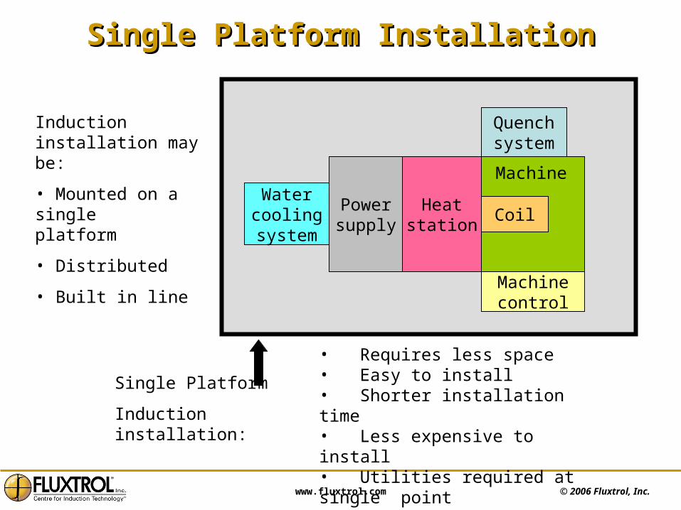
Single Platform InstallationSingle Platform Installation
• Requires less space• Easy to install• Shorter installation time• Less expensive to install• Utilities required at single point
Watercoolingsystem
Powersupply
Heatstation
Coil
Quenchsystem
Machinecontrol
Machine
Induction installation may be:
• Mounted on a single platform
• Distributed
• Built in line
Single Platform
Induction installation:
© 2006 Fluxtrol, Inc. www.fluxtrol.com
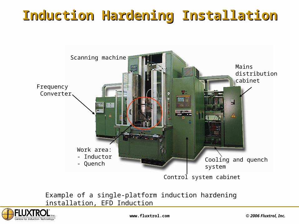
Induction Hardening InstallationInduction Hardening Installation
Frequency Converter
Scanning machine
Control system cabinet
Work area:- Inductor- Quench
Cooling and quench system
Mains distributioncabinet
Example of a single-platform induction hardening installation, EFD Induction

© 2006 Fluxtrol, Inc. www.fluxtrol.com
Power Supply Block DiagramPower Supply Block Diagram
Controlelectronics
3 phaseline input
AC to DC conversion
DC to AC
Loadmatching
transformer &capacitors
Induction coil
Command
Heat station
Inverter section
Rectifier section
Power supply must convert alternating line frequency power (50 or 60 Hz) into a controlled High Frequency power. The most effective way to do that is to convert (rectify) line frequency power into DC power and then generate high frequency using solid state Inverter.
HF Generator
© 2006 Fluxtrol, Inc. www.fluxtrol.com
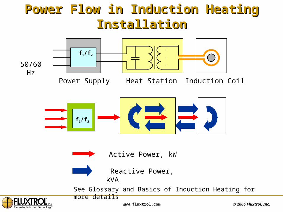
Power Flow in Induction Heating InstallationPower Flow in Induction Heating Installation
Active Power, kW
Reactive Power, kVA
f1/f2
f1/f2
Induction CoilHeat StationPower Supply
50/60 Hz
See Glossary and Basics of Induction Heating for more details
© 2006 Fluxtrol, Inc. www.fluxtrol.com
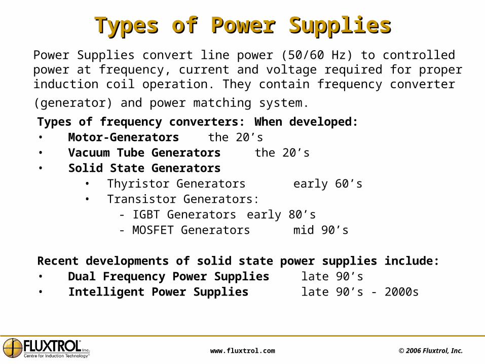
Types of Power SuppliesTypes of Power Supplies
Types of frequency converters: When developed:• Motor-Generators the 20’s• Vacuum Tube Generators the 20’s• Solid State Generators
• Thyristor Generators early 60’s• Transistor Generators: - IGBT Generators early 80’s - MOSFET Generators mid 90’s
Recent developments of solid state power supplies include:• Dual Frequency Power Supplies late 90’s• Intelligent Power Supplies late 90’s - 2000s
Power Supplies convert line power (50/60 Hz) to controlled power at frequency, current and voltage required for proper induction coil operation. They contain
frequency converter (generator) and power matching system.
© 2006 Fluxtrol, Inc. www.fluxtrol.com
Motor-Generator SetsMotor-Generator Sets
• Obsolete equipment but still used in industry
• Frequency limited up to 10 kHz
• Fixed frequency, no ability of load matching by frequency variation
• Power from 50 – 2500 kW
• Efficiency - 65 to 85 %
• Output voltage from 400 – 1600 Volts
• Rotating parts require maintenance due to wear and tear
• Big size and weight
• Difficult to repair
© 2006 Fluxtrol, Inc. www.fluxtrol.com
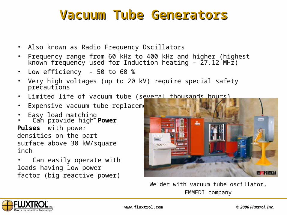
Vacuum Tube GeneratorsVacuum Tube Generators
• Also known as Radio Frequency Oscillators• Frequency range from 60 kHz to 400 kHz and higher (highest known frequency
used for Induction heating – 27.12 MHz)• Low efficiency - 50 to 60 %• Very high voltages (up to 20 kV) require special safety precautions• Limited life of vacuum tube (several thousands hours)• Expensive vacuum tube replacement • Easy load matching
• Can provide high Power Pulses with power densities on the part surface above 30 kW/square inch• Can easily operate with loads having low power factor (big reactive power)
Welder with vacuum tube oscillator,
EMMEDI company

© 2006 Fluxtrol, Inc. www.fluxtrol.com
Solid State GeneratorsSolid State Generators
• Any reasonable combination of frequency and power is possible
• Variable frequency in a range up to 10 times from the same generator with proper changes in heat station
• Power from 1 kW – 10 MW
• Output voltage from 200 – 1600 Volts
• High efficiency - up to 90- 95 %
• Multiple outputs possible
• Simultaneous dual frequency output possible
• Advanced controls
• Easily adaptable to modern automation techniques
• Light weight and compact size
Power supply 100 kW, 10 or 30 kHz
Inductoheat Inc.

© 2006 Fluxtrol, Inc. www.fluxtrol.com
Modern Solid State Power SuppliesModern Solid State Power SuppliesBig and Middle Sizes
Courtesy of EFD Induction, Inc.
© 2006 Fluxtrol, Inc. www.fluxtrol.com
Simultaneous Dual Frequency Power SuppliesSimultaneous Dual Frequency Power Supplies
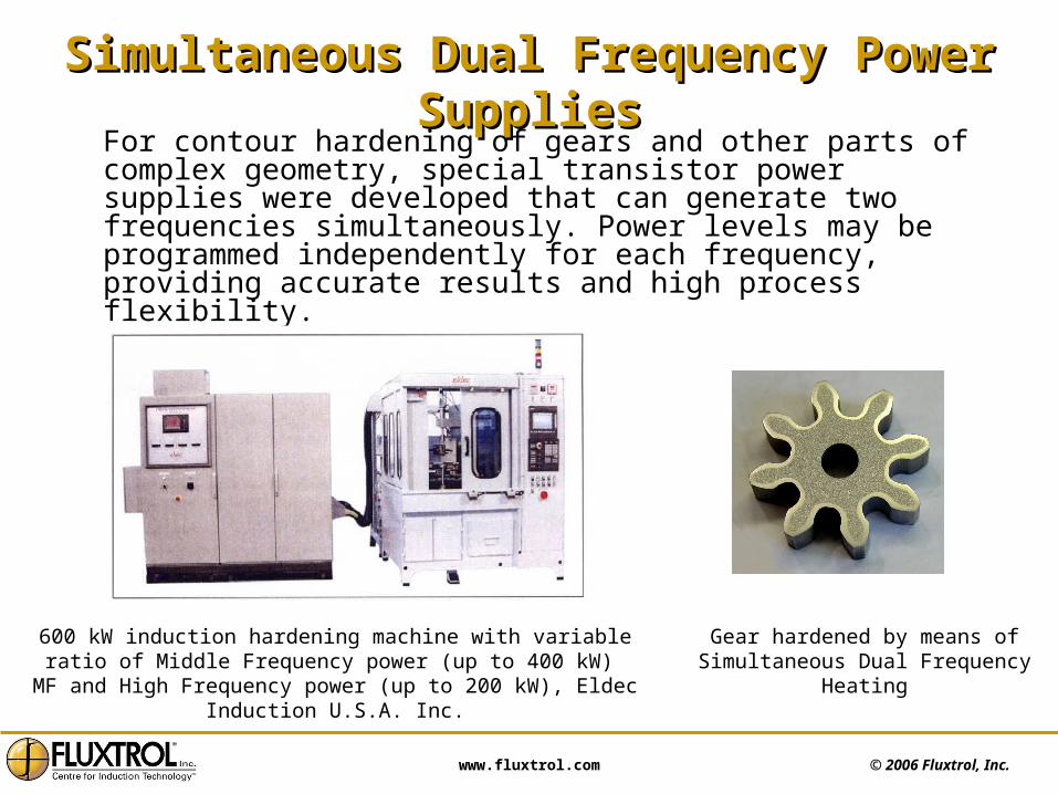
For contour hardening of gears and other parts of complex geometry, special transistor power supplies were developed that can generate two frequencies simultaneously. Power levels may be programmed independently for each frequency, providing accurate results and high process flexibility.
Gear hardened by means of Simultaneous Dual Frequency Heating
600 kW induction hardening machine with variable ratio of Middle Frequency power (up to 400 kW) MF and High Frequency power
(up to 200 kW), Eldec Induction U.S.A. Inc.

© 2006 Fluxtrol, Inc. www.fluxtrol.com
Intelligent Power SuppliesIntelligent Power Supplies
Modern power supplies can deliver almost any combination of power and frequency; they have high efficiency and small size.
The main tendency of further development is improvement in flexibility and controls leading to more intelligent machines.
Modern induction power supplies can provide: • Power generation in a wide range of frequency • Autotuning with coil change and coil parameter variation in the process of
heating• Process programming • Control from Master control system of the production line • Process monitoring• Automatic troubleshooting • Remote control and diagnostics including actions from the manufacturer site
Development of more advanced and sophisticated control systems may be expected including real-time process optimization and quality control.

© 2006 Fluxtrol, Inc. www.fluxtrol.com
Comparison of Power SuppliesComparison of Power Supplies
Type of Power Supply Switching device Frequency range
Efficiency of power supply %
Line frequency None 50/60 Hz 93 - 97
Motor-Generator None 1 kHz –10 kHz 70 – 85
Solid state SCR Thyristors 500 Hz – 25 kHz 87 - 95
Solid state IGBT Transistors 1 kHz – 200 kHz 85 - 92
Solid state MOSFET Transistors
100 kHz – 400 kHz
85 – 92
Vacuum Tube Generator
Vacuum tube 66 kHz – 500 kHz and more
50 - 60

© 2006 Fluxtrol, Inc. www.fluxtrol.com
Large Solid State Power Supplies / Large Solid State Power Supplies / Application AreasApplication Areas
Category Low Frequency
(LF)
Medium Frequency
(MF)
High (Radio) Frequency
(HF)
Frequency Range
50 Hz to 3 kHz
3 kHz to 60 kHz Above 60 kHz
Power Range
Up to 30 MW Up to 5000 KW Up to 1800 KW
Applications Melting
Mass Heating
Mass Heating
Heat Treating
Heat Treating
Bonding
Brazing
Tube welding
© 2006 Fluxtrol, Inc. www.fluxtrol.com
Large High Frequency Solid State Large High Frequency Solid State Power SupplyPower Supply
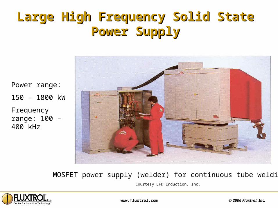
Power range:
150 – 1800 kW
Frequency range: 100 – 400 kHz
Courtesy EFD Induction, Inc.
MOSFET power supply (welder) for continuous tube welding
© 2006 Fluxtrol, Inc. www.fluxtrol.com
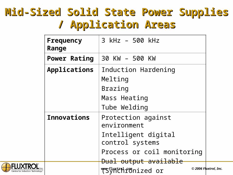
Mid-Sized Solid State Power Supplies / Mid-Sized Solid State Power Supplies / Application AreasApplication Areas
Frequency Range
3 kHz – 500 kHz
Power Rating 30 KW – 500 KW
Applications Induction Hardening
Melting
Brazing
Mass Heating
Tube Welding
Innovations Protection against environment
Intelligent digital control systems
Process or coil monitoring
Dual output available
(Synchronized or Independent)

© 2006 Fluxtrol, Inc. www.fluxtrol.com
Small Solid State Power Supplies / Small Solid State Power Supplies / Application AreasApplication Areas
Frequency Range 20 kHz – 500 kHz
Power Rating 1 kW – 25 kW
Applications Induction Hardening
Induction Brazing
Shrink fitting
Melting
Innovations Air cooled
Self tuning
Intelligent digital controls
Compact and low weight
Dual independent output available
Portable and handheld units available
Use of flexible cables for easy handling

© 2006 Fluxtrol, Inc. www.fluxtrol.com
Small Solid State Power Supplies Small Solid State Power Supplies
2kW, 150 - 400 kHz power generator with
heat station and chiller, Ameritherm Inc.
These power supplies are widely used for a variety of applications requiring high frequency and relatively small power such as:
• Melting
• Hardening
• Brazing
• Soldering
• Shrink-fitting etc.
Generators are typically air-cooled while heat stations have water cooling.
Individual heat exchangers or chillers become more and more popular

© 2006 Fluxtrol, Inc. www.fluxtrol.com
Dual Output Solid State Power SuppliesDual Output Solid State Power Supplies
Alternating duty• Utilizing one output at a time• Full power available on each output• Common inverter and control system
Parallel duty• Utilizing both outputs at the same time• Output power divided by the output transformers• Common inverter and control system
Twin Output • Two outputs with independent operation and controls• Common DC but two inverter sections• Outputs could be at different frequencies
Dual Output Power Supplies can work in one of the following work modes:
© 2006 Fluxtrol, Inc. www.fluxtrol.com
Dual Output Solid State Power SupplyDual Output Solid State Power Supply
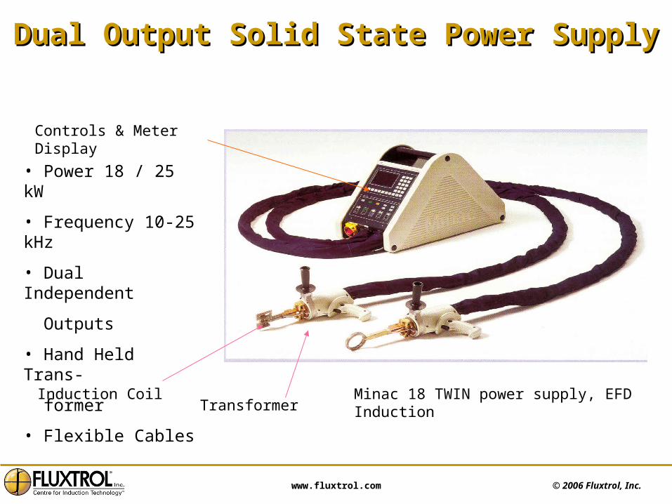
• Power 18 / 25 kW
• Frequency 10-25 kHz
• Dual Independent
Outputs
• Hand Held Trans-
former
• Flexible Cables
TransformerInduction Coil
Controls & Meter Display
Minac 18 TWIN power supply, EFD Induction
© 2006 Fluxtrol, Inc. www.fluxtrol.com
Power Supply Selection CriteriaPower Supply Selection Criteria
• Frequency
• Power rating
• Output voltage range
• Output current range
• Load matching capabilities
• Controls
• Efficiency
• Reliability
• Floor space
• Easy to operate and maintain
• Initial cost and repair cost
• Manufacturers experience and reputation
© 2006 Fluxtrol, Inc. www.fluxtrol.com
Load MatchingLoad Matching
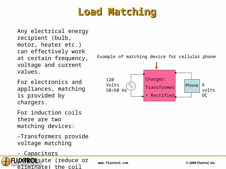
Any electrical energy recipient (bulb, motor, heater etc.) can effectively work at certain frequency, voltage and current values.
For electronics and appliances, matching is provided by chargers.
For induction coils there are two matching devices:
-Transformers provide voltage matching
- Capacitors compensate (reduce or eliminate) the coil reactive power
Example of matching device for cellular phone
Charger:
Transformer
+ Rectifier
120 Volts50/60 Hz
Phone 6 volts DC

© 2006 Fluxtrol, Inc. www.fluxtrol.com
Load Matching with Parallel CircuitryLoad Matching with Parallel Circuitry• Generators with parallel circuitry produces relatively “high” output voltage and
“low” output current• Coils require very high current at “low” voltage• Transformer reduces generator voltage to required level• Capacitor battery is necessary to compensate reactive power of the coil; it
reduces generator current to required value due to “parallel resonance”• With the proper load matching power supply could deliver maximum available
power to the coil at required voltage and current
Inductor50 Volts(example)
Generator800volts
Tuning Capacitor
MatchingTransformer
Generator delivers“high” voltage and“low” current
Coil demandslow voltage andvery high current
Heat Station

© 2006 Fluxtrol, Inc. www.fluxtrol.com
Load Matching with Series CircuitryLoad Matching with Series Circuitry• Generator produces “low” output voltage and “high” output current• Coils typically require even higher current at low voltage• Transformer reduces generator voltage and increases current to required level• Capacitor battery is necessary to compensate reactive power of the coil; it
reduces transformer primary voltage to required generator output value due to “series resonance”
• With the proper load matching power supply could deliver maximum available power to the coil at required voltage and current
Generator delivers“low” voltage and“high” current
Coil demandslow voltage andvery high current
Heat Station
Inductor50 Volts(example)
Generator800volts
Series Capacitor
MatchingTransformer

© 2006 Fluxtrol, Inc. www.fluxtrol.com
Heat StationHeat Station
• Utilized to match induction coil voltage & current to output voltage & current of generator
• Heat Station may contain:- Matching transformer - Tuning capacitors- Water cooling circuit components- Water pressure gauges and switches- Water temperature switch and other monitoring and
control devices• In small solid state power supplies heat station may be
housed inside the power unit for compactness, loss reduction in bus/cables and lower cost
© 2006 Fluxtrol, Inc. www.fluxtrol.com
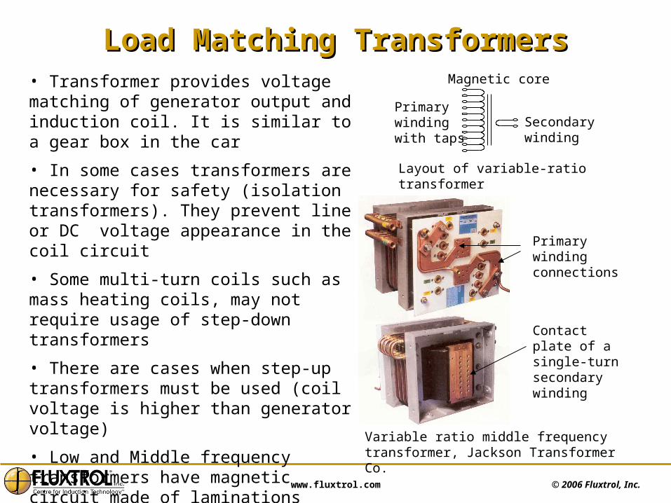
• Transformer provides voltage matching of generator output and induction coil. It is similar to a gear box in the car
• In some cases transformers are necessary for safety (isolation transformers). They prevent line or DC voltage appearance in the coil circuit
• Some multi-turn coils such as mass heating coils, may not require usage of step-down transformers
• There are cases when step-up transformers must be used (coil voltage is higher than generator voltage)
• Low and Middle frequency transformers have magnetic circuit made of laminations
• High frequency transformers have ferrite core or no core at all (air transformers)
Load Matching TransformersLoad Matching Transformers
Primary windingwith taps
Secondarywinding
Magnetic core
Layout of variable-ratio transformer
Variable ratio middle frequency transformer, Jackson Transformer Co.
Primary winding connections
Contact plate of a single-turn secondary winding
© 2006 Fluxtrol, Inc. www.fluxtrol.com
Capacitor BatteryCapacitor Battery
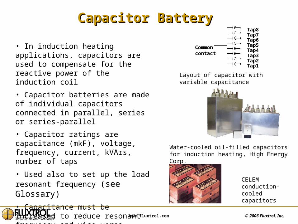
Commoncontact
Tap1Tap2Tap3Tap4Tap5Tap6Tap7Tap8
• In induction heating applications, capacitors are used to compensate for the reactive power of the induction coil
• Capacitor batteries are made of individual capacitors connected in parallel, series or series-parallel
• Capacitor ratings are capacitance (mkF), voltage, frequency, current, kVArs, number of taps
• Used also to set up the load resonant frequency (see Glossary)
• Capacitance must be increased to reduce resonant frequency and vice versa
• Capacitors may be water-cooled, conduction-cooled or air-cooled
Water-cooled oil-filled capacitors for induction heating, High Energy Corp.
Layout of capacitor with variable capacitance
CELEM conduction-cooled capacitors

© 2006 Fluxtrol, Inc. www.fluxtrol.com
Load Matching ProcedureLoad Matching Procedure
Step Controlled
Parameter
Recommended Value
Actual Value What to do?
One Frequency Inside of Rated Frequency Range
Low Reduce capacitance
High Add capacitance
Two
Voltage Both Voltage and Current should be in the same level of value to have high power
High Lower transformer ratio*
Current High Increase transformer ratio*
Power Maximum required Low Either increase voltage or current
For coil matched all three parameters (frequency, current and voltage) must be in rated range of power supply. Operating frequency must be close to a resonant frequency of the tank circuitry, which can be calculated as
with L – coil inductance in mkHC – capacitance in mkF
* Possibly it would be necessary to repeat Step 1 after changing the transformer ratio
F = 0.31/√(LC), kHz
© 2006 Fluxtrol, Inc. www.fluxtrol.com
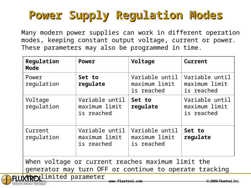
Power Supply Regulation ModesPower Supply Regulation Modes
Regulation Mode Power Voltage Current
Power regulation Set to regulate Variable until maximum limit is reached
Variable until maximum limit is reached
Voltage regulation Variable until maximum limit is reached
Set to regulate Variable until maximum limit is reached
Current regulation Variable until maximum limit is reached
Variable until maximum limit is reached
Set to regulate
When voltage or current reaches maximum limit the generator may turn OFF or continue to operate tracking the limited parameter
Many modern power supplies can work in different operation modes, keeping constant output voltage, current or power. These parameters may also be programmed in time.
© 2006 Fluxtrol, Inc. www.fluxtrol.com
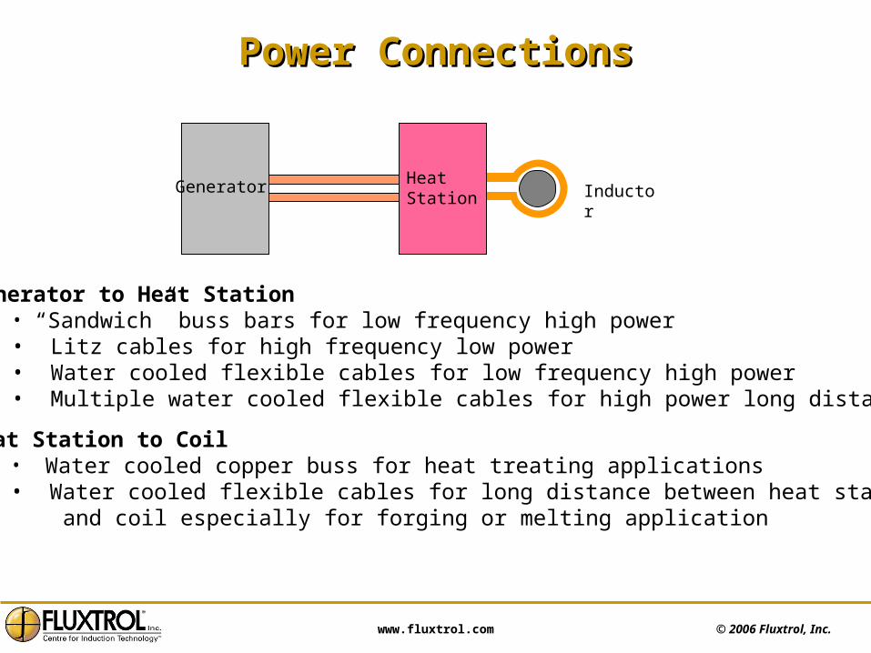
Power ConnectionsPower Connections
InductorHeatStation
Generator
Generator to Heat Station• “Sandwich” buss bars for low frequency high power• Litz cables for high frequency low power• Water cooled flexible cables for low frequency high power• Multiple water cooled flexible cables for high power long distance
Heat Station to Coil• Water cooled copper buss for heat treating applications• Water cooled flexible cables for long distance between heat station and coil especially for forging or melting application
© 2006 Fluxtrol, Inc. www.fluxtrol.com
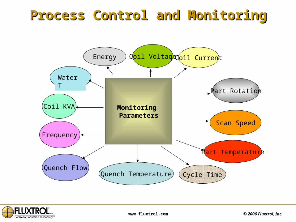
Process Control and MonitoringProcess Control and Monitoring
Water T
Monitoring Parameters
Coil KVA
Quench FlowQuench Temperature
Part temperature
Coil Voltage Coil Current
Part Rotation
Scan Speed
Frequency
Energy
Cycle Time

© 2006 Fluxtrol, Inc. www.fluxtrol.com
Layout of Induction Circuit with SensorsLayout of Induction Circuit with Sensors
Ui UB
Ui – Coil Current Signal
Uu – Voltage Signal
UB – Flux Density Signal
Uu
Induction coil withFlux concentrator

© 2006 Fluxtrol, Inc. www.fluxtrol.com
Process MonitorsProcess Monitors
Digital control system
Simulation - Digital control system
Process monitoring is one of the most important features of modern induction installations.
There are many types of monitoring systems from relatively simple coil monitors to sophisticated multi-functional devices.
Monitors can provide:• Measurement of electrical parameters – current, voltage, power • Part temperature control • Control of part rotation and scan speed, cooling and quenching conditions etc.• Process repeatability control and detection of faulty conditions• Gathering information for data storage and trend analysis
Use of monitors improves quality control, facilitate troubleshooting, saves time and costs due to reduction of destructive tests Quality Assurance Monitor, Inductoheat Inc.
Up to 8 critical parameters may be monitored in real time
© 2006 Fluxtrol, Inc. www.fluxtrol.com
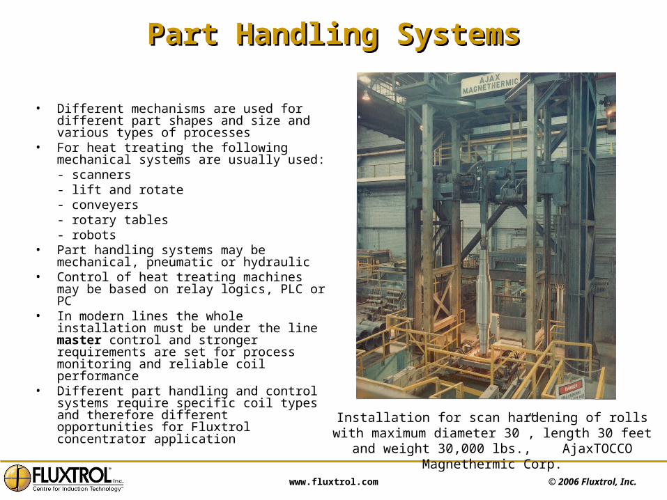
Part Handling SystemsPart Handling Systems
• Different mechanisms are used for different part shapes and size and various types of processes
• For heat treating the following mechanical systems are usually used:- scanners- lift and rotate - conveyers- rotary tables- robots
• Part handling systems may be mechanical, pneumatic or hydraulic
• Control of heat treating machines may be based on relay logics, PLC or PC
• In modern lines the whole installation must be under the line master control and stronger requirements are set for process monitoring and reliable coil performance
• Different part handling and control systems require specific coil types and therefore different opportunities for Fluxtrol concentrator application Installation for scan hardening of rolls with maximum
diameter 30”, length 30 feet and weight 30,000 lbs., AjaxTOCCO Magnethermic Corp.
© 2006 Fluxtrol, Inc. www.fluxtrol.com
Water Cooling and Quenching SystemsWater Cooling and Quenching Systems
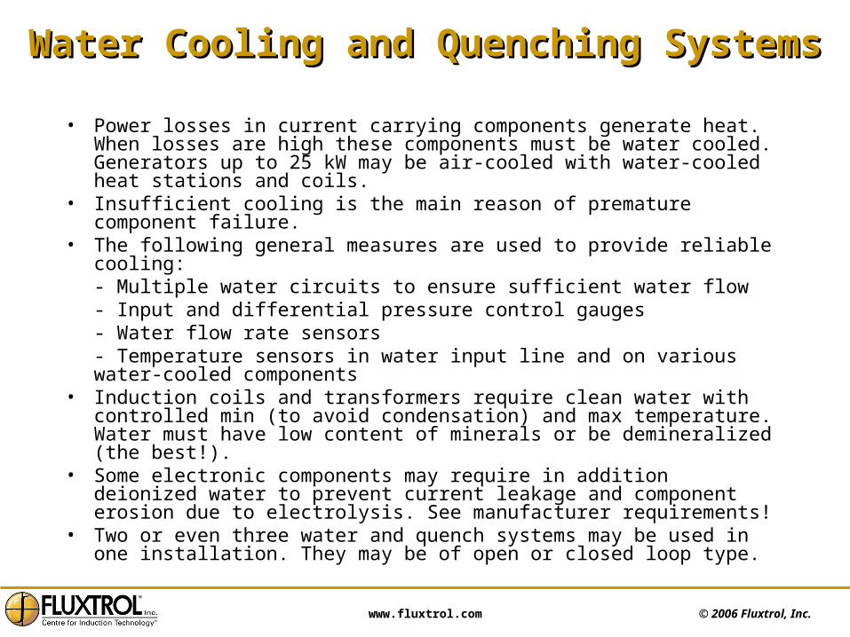
• Power losses in current carrying components generate heat. When losses are high these components must be water cooled. Generators up to 25 kW may be air-cooled with water-cooled heat stations and coils.
• Insufficient cooling is the main reason of premature component failure.• The following general measures are used to provide reliable cooling:
- Multiple water circuits to ensure sufficient water flow- Input and differential pressure control gauges- Water flow rate sensors - Temperature sensors in water input line and on various water-cooled components
• Induction coils and transformers require clean water with controlled min (to avoid condensation) and max temperature. Water must have low content of minerals or be demineralized (the best!).
• Some electronic components may require in addition deionized water to prevent current leakage and component erosion due to electrolysis. See manufacturer requirements!
• Two or even three water and quench systems may be used in one installation. They may be of open or closed loop type.

© 2006 Fluxtrol, Inc. www.fluxtrol.com
Typical Closed Loop Water Cooling SystemTypical Closed Loop Water Cooling System
Generator HeatStation &Coil
HeatExchanger
Cooling Water
Filter
Reservoir
Clean water
Pump
© 2006 Fluxtrol, Inc. www.fluxtrol.com
ConclusionsConclusionsThere are many installations now to choose from:• Wide range of combinations “Power – Frequency” • Wide range of types and design• Choice of installations adapted to a variety of applications• Choice of universal installations with good matching ability in wide frequency range
Modern power supplies may be:• Small in size and weight• Very efficient • Easy to operate and maintain• Adapted to automated systems
Flux concentrators on induction coils can improve the installation performance:• Reduce coil power demand or increase production rate• Reduce installation size and price• Improve efficiency of power supply due to reduced coil current demand• Reduce external magnetic fields (shielding!) resulting in:
- Safer environment for operators- No interference to computerized control systems- No unintended heating of machine components- Eliminate “cross-talking” in multi-generator systems

© 2006 Fluxtrol, Inc. www.fluxtrol.com
QuestionsQuestions
• An induction Process can be defined by a combination of? Power, Time, Frequency
• In Induction Heating line power is converted from AC to DC and then back to AC for what reason? To achieve controllable output power at desired frequency
• What are the 3 main types of power supplies? Motor Generator, Vacuum Tube, Solid State
• What switching devices are used in solid state power supplies? Thyristors and Transistors
• What types of power supplies can generates two frequencies simultaneously?Dual Frequency and Twin Output
• The types of power supplies are? Alternating Duty, Parallel Duty, Twin Output
• Can line or DC voltage appear on the coil if it’s connected to the power supply through a matching transformer? No
• What are the 2 devices in induction installations used for coil matching? Transformers and Capacitors
• A Capacitor Battery is required to compensate for coil ….? Reactive Power
• The components used to match the coil voltage and current to the output voltage and current of the generator are in the …? Heat Station
• The taps on a transformer in the heat station are used to? Change transformer ratio and adjust output voltage
• What coil cooling water parameters it is necessary to control?Temperature, pressure , mineral content
Click to scroll Questions and Answers