Principles of electrical science - Pearson · PDF fileLevel 2 Electrical Installations ... An...
64
1 1 UNIT 204 Principles of electrical science 1 Chapter 1 LEVEL 2
-
Upload
truongnguyet -
Category
Documents
-
view
216 -
download
1
Transcript of Principles of electrical science - Pearson · PDF fileLevel 2 Electrical Installations ... An...

11
UNIT 204
Principles of
electrical science
1
Chapter 1LEVEL 2
Level 2 Electrical Installations (Buildings and Structures)
2
Chapter
1
IntroductionElectricity and the science behind it can be tricky, especially because you can’t see it – all you can do is see the e ects of it or feel it. In this chapter you will investigate some of the basic scienti c principles of electricity, and the applications and uses that are fundamental to a technician’s role in the building services engineering industry. This chapter is broken down into logical sections to enable you to grasp the science and progress on to the Level 3 science syllabus. You will be introduced to the basic concepts followed by worked examples, backed up by a range of practice questions at di erent levels. The order of the learning outcomes has been changed slightly from the C&G speci cation in some instances: this is to allow a logical build-up of knowledge before you progress to the next subject.
This chapter covers: the principles of
electricity the principles of basic
electrical circuits the principles of
magnetism and electromagnetism
the operating principles of a range of electrical equipment
the principles of basic mechanics
the principles of a.c. theory
electrical quantities in Star Delta con gurations.
THE PRINCIPLES OF ELECTRICITYElectricity is simply the movement of electrons carrying energy. As electrons move along a conductor they have the ability to transfer some of their energy into other forms such as heat, light or movement. Your job as a building services engineer is to install and maintain systems that make use of this transferred electron energy. Electricians need to understand what electricity is in order to predict how it will react under di erent conditions.
The structure of matterIn order to understand electricity, we need to also consider some basic scienti c principles.
MatterMatter can come in di erent states and can change from one state to another. An example is ice turning to water and then steam. All three states – the ice, water and steam – have the same molecular chemical structure; they simply change state when subjected to a temperature change.
The atomAn atom is made up of subatomic particles and it is the properties of an atom that are of particular interest to an electrician.
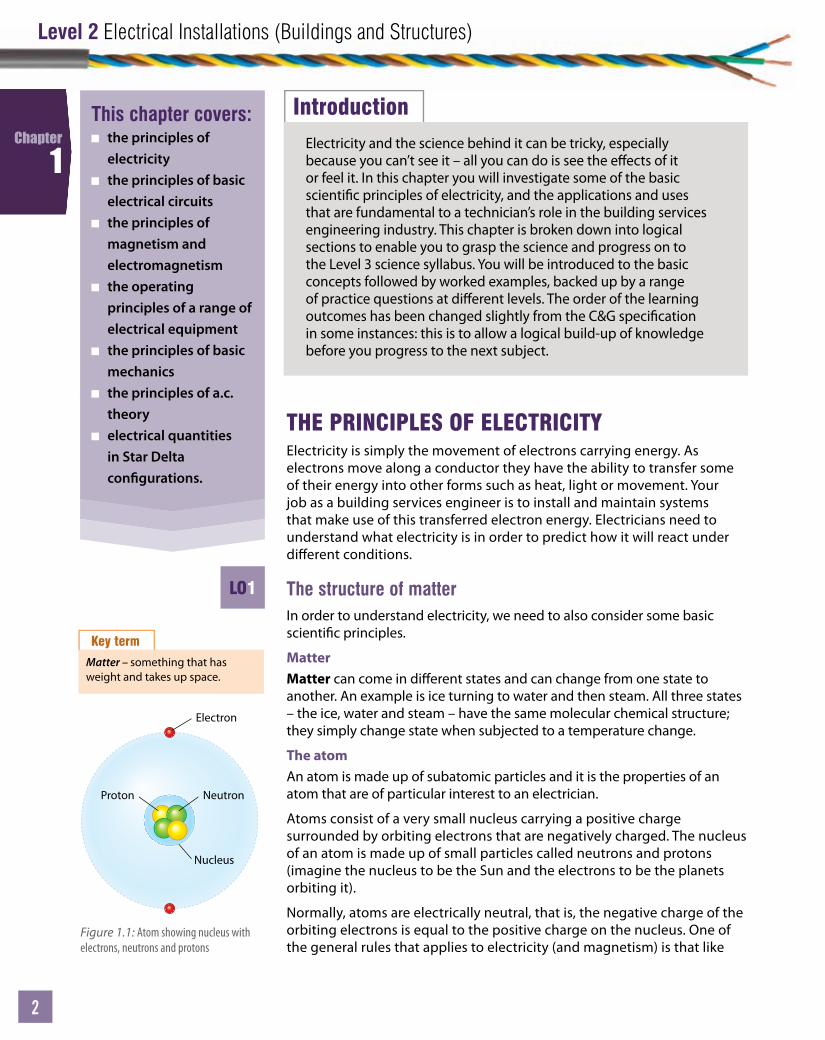
Atoms consist of a very small nucleus carrying a positive charge surrounded by orbiting electrons that are negatively charged. The nucleus of an atom is made up of small particles called neutrons and protons (imagine the nucleus to be the Sun and the electrons to be the planets orbiting it).
Normally, atoms are electrically neutral, that is, the negative charge of the orbiting electrons is equal to the positive charge on the nucleus. One of the general rules that applies to electricity (and magnetism) is that like
Key term
Matter – something that has weight and takes up space.
Electron
Neutron
Nucleus
Proton
Figure 1.1: Atom showing nucleus with electrons, neutrons and protons
LO1
Unit
3
Chapter 1: Principles of electrical science
3
3
Chapter
1
charges repel and unlike charges attract, so within an atom the electrons in the outer shell are attracted to the positive protons. Neutrons are neutral in charge but act as the glue holding the atom together. It is the electrons in the outer shell that determine if a material is going to be a good insulator (like glass) or a good conductor (like copper). In insulators the electrons are rmly bound to the atom taking a lot of force to break them free. In good conductors such as metals, the electrons appear to be relatively free and with a little encouragement they can be broken o and set free to nd something more positive. It is this movement of ‘free’ electrons that is known as current and hence electricity. A free-moving electron is said to be a ‘charge carrier’ because it is carrying a negative charge of energy as it moves through a conductor.
To get a feel of the strength of an electric current, imagine the ow of negatively charged electrons as a ow of water down a river. A strong current would be a large amount of water passing a point in a certain time. So a strong or large electric current would be a large volume of electric charge (free electrons) passing a point in a certain time. It is important for you to understand charge because without it there would be no electricity. Charge is a quantity of electricity and it is the movement of charge that gives rise to current ow in a circuit.
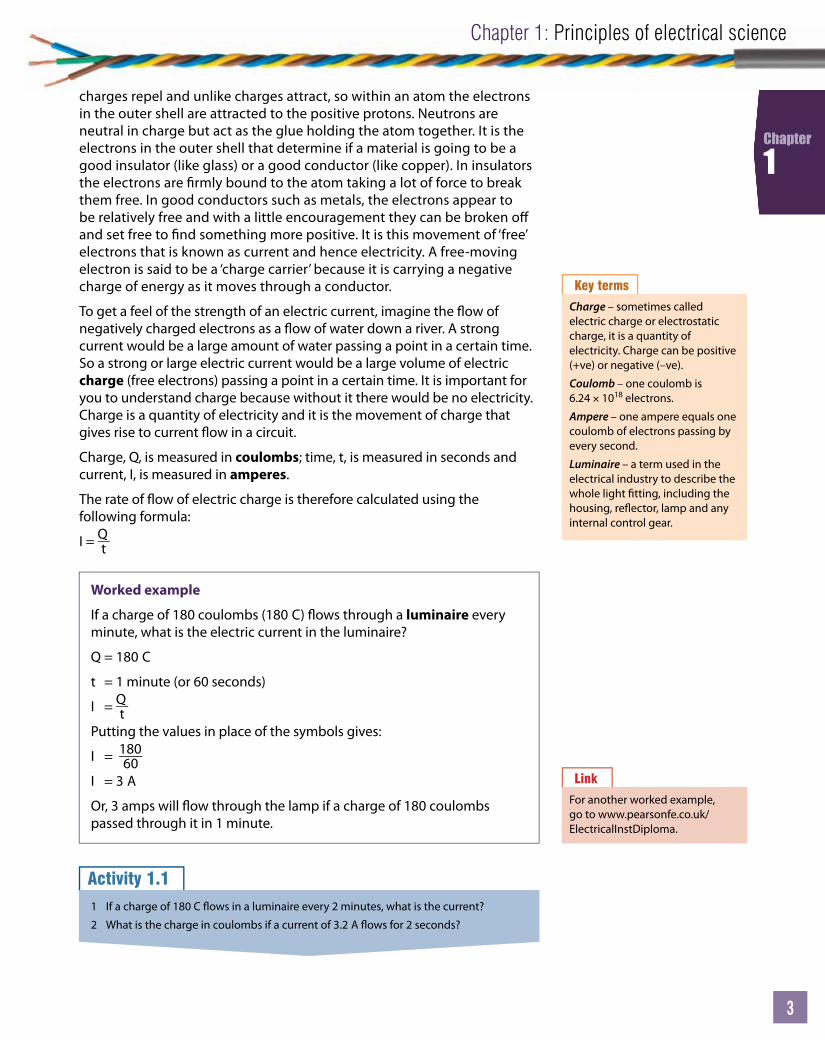
Charge, Q, is measured in coulombs; time, t, is measured in seconds and current, I, is measured in amperes.
The rate of ow of electric charge is therefore calculated using the following formula:
I = Qt
Key terms
Charge – sometimes called electric charge or electrostatic charge, it is a quantity of electricity. Charge can be positive (+ve) or negative (–ve).
Coulomb – one coulomb is 6.24 × 10¹⁸ electrons.
Ampere – one ampere equals one coulomb of electrons passing by every second.
Luminaire – a term used in the electrical industry to describe the whole light tting, including the housing, re ector, lamp and any internal control gear.
Worked example
If a charge of 180 coulombs (180 C) ows through a luminaire every minute, what is the electric current in the luminaire?
Q = 180 C
t = 1 minute (or 60 seconds)
I = QtPutting the values in place of the symbols gives:
I = 18060
I = 3 A
Or, 3 amps will ow through the lamp if a charge of 180 coulombs passed through it in 1 minute.
Link
For another worked example, go to www.pearsonfe.co.uk/ElectricalInstDiploma.
Activity 1.11 If a charge of 180 C ows in a luminaire every 2 minutes, what is the current?
2 What is the charge in coulombs if a current of 3.2 A ows for 2 seconds?

Level 2 Electrical Installations (Buildings and Structures)
4
Chapter
1
Potential di erence and voltageA current will ow if ‘free’ electrons are encouraged to break away from an atom. What encourages this ow to happen? Using the example of water, imagine water in a pond and also water in a river. Water in a pond is still, so there is no ow or current. Water in a river, however, does have the potential to ow. The strength of the current ow depends on the di erence in height between the top of the river and the bottom – the steeper the drop, the faster the current. In an electrical circuit this is the same basic principle.
Figure 1.2: Flow of water and potential energy
Electrons with high potential energy
Conductor withelectrons moving
throughCurrent/electron owdepends on resistanceand voltage pressure/
potential dierenceElectrons pumpor battery moveselectrons up hill
Electrons with low potential energy
Figure 1.3: Flow of electrons and potential di erence
An electric circuit has a high ‘charge’ point and a lower ‘charge’ point. These are the +ve and –ve terminals of a battery of supply. The height in the circuit is known as the voltage and the di erence between the high point and the low point is called the ‘potential di erence’ (otherwise known as p.d.). The battery or electrical source acts as a pump, moving the charge to the top of the hill where it has potential energy and then it can fall down the hill giving up potential energy in the form of heat or light (for example, going through a heat element or a luminaire). Potential di erence, often referred to as ‘voltage across’ or simply ‘voltage’, is measured in volts and the greater the p.d., the greater potential for current ow in a circuit.
Water with high potential energyWater falls down hill
Force depends onhow high it falls
Pump moves water up hill
Water with low potential energy
Water

Unit
5
Chapter 1: Principles of electrical science
5
5
Chapter
1
Sources of an electromotive force (emf)There are a number of ways in which electromotive force, or emf, can be generated. Electricity can be the output of a chemical, magnetic or thermal reaction. The way electricity is generated depends on a number of factors and circumstances.
Magnetic emf source – if electricity is required at a location where there happens to be a large volume of moving water, then it makes sense, from an ecological point of view, to use this force of nature to turn a turbine. By moving a conductor within a magnetic eld, a current can be generated in that conductor as long as there is a circuit. This e ect is called electromagnetic induction and this is how a basic turbine works.
Magnetic eld + conductive circuit + movement = electromotive force and current ow
Thermal emf source – if two metals with di erent chemical properties are connected together, an emf will be generated across the junction if the two sides of the junction are at slightly di erent temperatures. E ectively there is a potential di erence between the two sides that is enough to cause electrons to want to move. The principle of converting heat energy directly to electrical energy is known as the Seebeck or thermoelectric e ect. A use for this e ect is the thermocouple where the device is used to measure temperature.
Chemical emf source – a battery cell works on the principle of creating an emf by chemical reaction. Within the cell there is a chemical called an acid solution or ‘electrolyte’. If two di erent types of metal strips are put into the acid, an electromotive force appears between the two plates. If the circuit is completed by joining the metal plates at the top with a conductor, a path is now available for the free electrons to move through.
The –ve plate is the zinc and the +ve plate is made of copper. As the connected plates are put into the acid electrolyte solution, the zinc will start to dissolve. The zinc atoms then leave the zinc plate and enter the solution. As each zinc atom leaves the plate and enters the acid, it leaves behind two electrons. This has the e ect of making the zinc plate more negative and the atom more positive (due to losing two of its electrons). The +ve zinc atoms are not attracted to the +ve hydrogen atoms in the acid solution and they are pushed to the –ve charged copper plate where the hydrogen grabs a copper electron. When the reaction occurs between the copper electron and the hydrogen atom, the copper plate becomes more +ve due to the loss of an electron. This reaction causes a potential di erence to appear between the two plates, creating what is e ectively a ‘chemical pump’ or an emf source.
Key term
Electromotive force (emf) – a source of energy that can cause current to ow.
Figure 1.4: Electron ow through an electrolyte
E
– +

Level 2 Electrical Installations (Buildings and Structures)
6
Chapter
1
Effects of electric currentChemical e ect – as described with a battery cell, by passing a current through an electrolyte a chemical reaction will take place. The process that happens can be useful. One such process is called ‘electrolysis’ and is used to electroplate metals. An example of electroplating is chrome plating to give a soft metal a harder-wearing nish. The chrome coating is useful for tools or car parts to stop corrosion or rust.
Magnetic e ect – if you connect a battery to a circuit consisting of a lamp, conductor and a switch, and turn the circuit on, several things happen. Firstly, the lamp goes on. If you put an ammeter into the circuit you would notice the current growing from ‘0’ to a value. If you had a meter that could measure magnetism, you would notice that as the current grows, a magnetic eld would grow. The magnetic eld would grow to a maximum at the same time as the current – they are directly related and proportional.
Figure 1.5: Simple battery circuit and broken circuit
Thermal e ect – electrons passing through a conductor of any type will produce a third e ect: heat. As an electron is given energy to move by the emf, some energy is converted into other forms. This might be light and heat. Remember, energy is never lost, it is only ever converted into another form. Sometimes this heating e ect is useful, as in a heating element of a re or an infrared light. At other times the heating e ect of current ow is not useful – cables overheating in a domestic installation causing a house re.
Electrical quantities and SI unitsYou will come across many terms, symbols and abbreviations when dealing with the science around electricity. It is very important to get a good understanding of how they are used and applied.
The language of science has been standardised into the SI system of units so that it can be understood all over the world. Most countries now use SI units.
Unit
7
Chapter 1: Principles of electrical science
7
7
Chapter
1
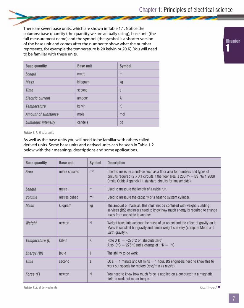
There are seven base units, which are shown in Table 1.1. Notice the columns: base quantity (the quantity we are actually using), base unit (the full measurement name) and the symbol (the symbol is a shorter version of the base unit and comes after the number to show what the number represents, for example the temperature is 20 kelvin or 20 K). You will need to be familiar with these units.
Base quantity Base unit Symbol
Length metre m
Mass kilogram kg
Time second s
Electric current ampere A
Temperature kelvin K
Amount of substance mole mol
Luminous intensity candela cd
Table 1.1: SI base units
As well as the base units you will need to be familiar with others called derived units. Some base units and derived units can be seen in Table 1.2 below with their meanings, descriptions and some applications.
Base quantity Base unit Symbol Description
Area metre squared m² Used to measure a surface such as a floor area for numbers and types of circuits required (2 × A1 circuits if the floor area is 200 m² – BS 7671:2008 Onsite Guide Appendix H, standard circuits for households).
Length metre m Used to measure the length of a cable run.
Volume metres cubed m³ Used to measure the capacity of a heating system cylinder.
Mass kilogram kg The amount of material. This must not be confused with weight. Building services (BS) engineers need to know how much energy is required to change mass from one state to another.
Weight newton N Weight takes into account the mass of an object and the effect of gravity on it. Mass is constant but gravity and hence weight can vary (compare Moon and Earth gravity!).
Temperature (t) kelvin K Note 0°K = –275°C or ‘absolute zero’Also, 0°C = 275°K and a change of 1°K = 1°C
Energy (W) joule J The ability to do work.
Time second s 60 s = 1 minute and 60 mins = 1 hour. BS engineers need to know this to work out speeds for motors (revs/min vs revs/s).
Force (F) newton N You need to know how much force is applied on a conductor in a magnetic field to work out motor torque.
Continued Table 1.2: SI derived units
Level 2 Electrical Installations (Buildings and Structures)
8
Chapter
1
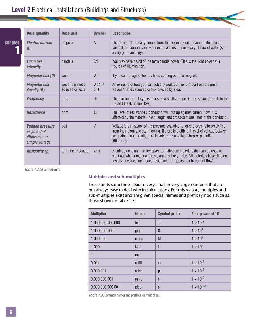
Base quantity Base unit Symbol Description
Electric current (I)
ampere A The symbol ‘I’ actually comes from the original French name l’intensité du courant, as comparisons were made against the intensity of flow of water (still a very good analogy).
Luminous intensity
candela Cd You may have heard of the term candle power. This is the light power at a source of illumination.
Magnetic flux (Ø) weber Wb If you can, imagine the flux lines coming out of a magnet.
Magnetic flux density (B)
weber per metre squared or tesla
Wb/m² or T
An example of how you can actually work out the formula from the units – webers/metres squared or flux divided by area.
Frequency herz Hz The number of full cycles of a sine wave that occur in one second: 50 Hz in the UK and 60 Hz in the USA.
Resistance ohm Ω The level of resistance a conductor will put up against current flow. It is affected by the material, heat, length and cross-sectional area of the conductor.
Voltage pressure or potential difference or simply voltage
volt V Voltage is a measure of the pressure available to force electrons to break free from their atom and start flowing. If there is a different level of voltage between two points on a circuit, there is said to be a voltage drop or potential difference.
Resistivity (ρ) ohm metre square Ωm² A unique constant number given to individual materials that can be used to work out what a material’s resistance is likely to be. All materials have different resistivity values and hence resistance (or opposition to current flow).
Table 1.2: SI derived units
Multiples and sub-multiples
These units sometimes lead to very small or very large numbers that are not always easy to deal with in calculations. For this reason, multiples and sub-multiples exist and are given special names and pre x symbols such as those shown in Table 1.3.
Multiplier Name Symbol prefix As a power of 10
1 000 000 000 000 tera T 1 × 10¹²
1 000 000 000 giga G 1 × 10⁹
1 000 000 mega M 1 × 10⁶
1 000 kilo k 1 × 10³
1 unit
0.001 milli m 1 × 10⁻³
0.000 001 micro μ 1 × 10⁻⁶
0.000 000 001 nano n 1 × 10⁻⁹
0.000 000 000 001 pico p 1 × 10–12
Table 1.3: Common names and pre xes for multipliers
Unit
9
Chapter 1: Principles of electrical science
9
9
Chapter
1Worked example
Convert 34 000 000 J into a number with a pre x.
Divided by 1 000 it would become 34 000 kJ.
If you divide 34 000 000 by 1 000 000 it would become 34 MJ.
Table 1.3 shows that multipliers are arranged into groups of thousands, millions, billions and thousandths, millionths, billionths, etc. By dividing a number by 1 000 and replacing the 0s with a pre x k, the number looks simpler and, providing you have good calculator skills, it becomes much easier to handle.
Electrical maths for building services engineersYou will be aware by now that a certain amount of maths is required in the building services sector. Amongst others, you will need to be able to work out:
• values of current a circuit can carry• the size of a cable based on what it is going to power• the force on a conductor• the speed of a motor• the missing sides or angles on power triangles• the torque of a turning force.
The list goes on – in fact, most aspects of a professional engineer’s work require maths. Some of the most important maths skills which are going to be covered in this section include:
• basic rules of numbers• transposition of formulae• trigonometry, triangles and Pythagoras.
Link
For another worked example, go to www.pearsonfe.co.uk/ElectricalInstDiploma.
Progress check 1.1
1 What does the symbol pre x ‘m’ mean?
2 What does the pre x ‘µ’ mean?
3 What is the base unit for weight?
Activity 1.21 Convert 0.0048 F into a number with a pre x.
2 Convert 4.5 mF into a number without a pre x.
3 Show 1.2 TN as MN.
4 Change 64 µf into mf.
5 Represent 0.000 000 135 A as mA.

Level 2 Electrical Installations (Buildings and Structures)
10
Chapter
1
You will use a wide range of formulae by the end of Level 3 training and the formulae will rarely be ready to use – you will have to change it around to make what you want to nd the subject. The rules are fairly straightforward but the key is lots of practice until it becomes second nature. Once you have practised and mastered transposition you will be able to change around the most complex formulae as needed. Understanding the actual number you have been given or which you have taken o a meter is also essential, because if you get it wrong you could put yourself or others at serious risk.
Basic mathematical conceptsFor all engineers to get the same correct answers, everyone needs to be working to the same basic rules.
You may have seen the term BODMAS before. It is used to decide in what order you should complete a calculation. If you have a mathematical expression and need to nd out what it is equal to, then you need to tackle it in the right order. If you do it in the wrong order you will get the wrong answer, as can be seen in the following example:
5 × (5 + 5) = 50 (complete what is inside the brackets rst to give 5 × 10 = 50)
If this was done in a di erent order you could get:
5 × 5 + 5 = 25 + 5 = 30 (giving a wrong answer)
How does BODMAS work?
BODMAS stands for:
Brackets If there are brackets around any part of the maths expression then this must be acted on rst, ignoring all other parts.
Other operations This refers to powers and roots being dealt with next.
Division Division and multiplication must be completed next, starting from the left.
Multiplication Multiplication and division both have the same priority but you must start from the left and work to the right. Note that sometimes a number might be next to a bracket – even though there is no ‘×’ sign, it still means multiplication needs to happen.
Addition Having completed all the other maths operations, there should only be addition and subtraction left in the expression to deal with.
Subtraction Addition and subtraction have the same priority so start from the left and work to the right until all the terms have been completed.

Unit
11
Chapter 1: Principles of electrical science
11
11
Chapter
1
Formulae transposition (rearranging formulae)The ability to change formulae around is an important skill for engineers. If there are three things in a formula, you normally will know two of the values but need to work out the third. This is where the di culty occurs, as the formula will not necessarily be arranged in such a way to give you the answer. You will need to rearrange the formula to nd what you need.
There are several ways to approach formulae transposition. The best way is to practise long hand until you are completely con dent.
Worked example
4(7 – 3)2 × 5 + 3Brackets:(7 – 3) = 4Operations:(4)² = 16Division and multiplication:There is no division so move on to multiplication (starting from left!)4(16) = 6464 × 5 = 320Addition and subtraction:Final solution:320 + 3 = 323
Link
For another worked example, go to www.pearsonfe.co.uk/ElectricalInstDiploma.
Activity 1.3Resolve the following mathematical expressions:
1 (9 + 7) × 1 + 3
2 (4 + 4 – 3 + 1)2 + 3 + 3
3 (7 + 8) ÷ 3 + 3
4 (7 + 7 × 7) × (3 + 3)
Worked example
5 = 3 + 2
We can rearrange this simple formula in a number of di erent ways:
5 – 3 = 25 – 2 = 3–3 = –5 +2 (or –3 = 2 – 5)–2 = 3 – 5 (or –2 = –5 + 3)
If the number moves to the other side of the ‘=’ it changes sign from + to – or – to +.

Level 2 Electrical Installations (Buildings and Structures)
12
Chapter
1
Numbers can also be replaced with letters, as follows:
A = B + CA – B = CA – C = B–C = –A + B (or –C = B – A)–B = C – A (or –B = –A + C)
When a number or symbol moves from one side of the ‘equals’ to the other, the sign must change from +ve to –ve or vice versa.
Multiplication and division operationsElectrical equations are not all simply addition and subtraction: other functions such as multiplication, division, square roots and squares are common.
Worked exampleRearrange the following formula to make ‘I’ the subject.
Imagine you have numbers for V and R (V = 100 volts and R = 50 ohms) but you need to work out what I is equal to.
V = IR
It doesn’t matter what side of the ‘=’ the ‘I’ is but it needs to be alone. To do this you need to remove the ‘R’ by rearranging the formula.
One option is to divide by ‘R’. If you divide something by itself the answer is 1 – regardless of whether it is a number or even a symbol!
This means if you divide R by R the answer will be 1. If you divide one side of the formula by something the rule states you must do the same to the other side as well. This keeps the formula balanced (like a see-saw). Remember this, as it is very important!
V = I × R
V = I × RR R
Both sides have been divided by R. Remember, if you have R divided by R this is the same as 1 so they must cancel out.
V = I × RR R
V = IR
Notice R has moved from one side to the other to leave the ‘I’ the subject, all by itself. Also note that in moving from one side to the other it has turned from multiplication to division (moved from above the line to below the line). This would be the same if it were to move in the reverse direction. This means that if something moves from one side of a formula to the other, the operation becomes the opposite.Examples:
√_A becomes A² and vice versa
Ax becomes 1A

Unit
13
Chapter 1: Principles of electrical science
13
13
Chapter
1
TrigonometryOne of the most important maths tools that you will need to use is trigonometry. Trigonometry is used to nd missing angles or missing sides of a right-angled triangle. This is necessary in many electrical applications such as:
• power factors• impedance triangles• a.c. single-phase theory• a.c. three-phase theory• power triangles.
The ‘opposite’ is always the side opposite the angle being considered.
If the angle being investigated changed to the top right-hand corner then the opposite and adjacent would swap – simply change around the sides to suit.
The hypotenuse is always the longest side. The adjacent is always the side that is left after you have worked out the others – simple!
Sine, cosine and tangentNow you know how to work out hypotenuse, adjacent and opposite sides, the angles can be introduced. Sine, cosine and tangent functions on your calculator can be used to nd the relationship between the sides of a triangle:
Sin Ø = OppositeHypotenuse
Cos Ø = AdjacentHypotenuse
Tan Ø = OppositeAdjacent
Summary of simple rules
Rule 1Whatever you do to one side of a formula you do to the other side also.
Rule 2If something is divided by itself it is equal to ‘1’ and can be cancelled out/simpli ed.
Rule 3To make something the subject of a formula, you need to get it by itself.
Rule 4By moving a term from one side of the formula to the other, you reverse the operation so divide becomes multiply and vice versa.
Opposite(to the angle)
Hypotenuse
(always the longest side)
Adjacent(to the angle)
Ø
Adjacent(to the angle)
Hypotenuse
(always the longest side)
Opposite(to the angle)
Ø
Figure 1.6: Pythagoras’ theorem
Figure 1.7: How to identify the sides and angles in Pythagoras’ theorem
To remember these formulae use the following name, SOHCAHTOA, which shows:
• sine (shortened to sin) of an angle equals opposite over hypotenuse• cosine (shortened to cos) of an angle equals adjacent over hypotenuse• tangent (shortened to tan) of an angle equals opposite over adjacent.
Link
For more information on Pythagoras’ theorem, go to www.pearsonfe.co.uk/ElectricalInstDiploma.
Level 2 Electrical Installations (Buildings and Structures)
14
Chapter
1
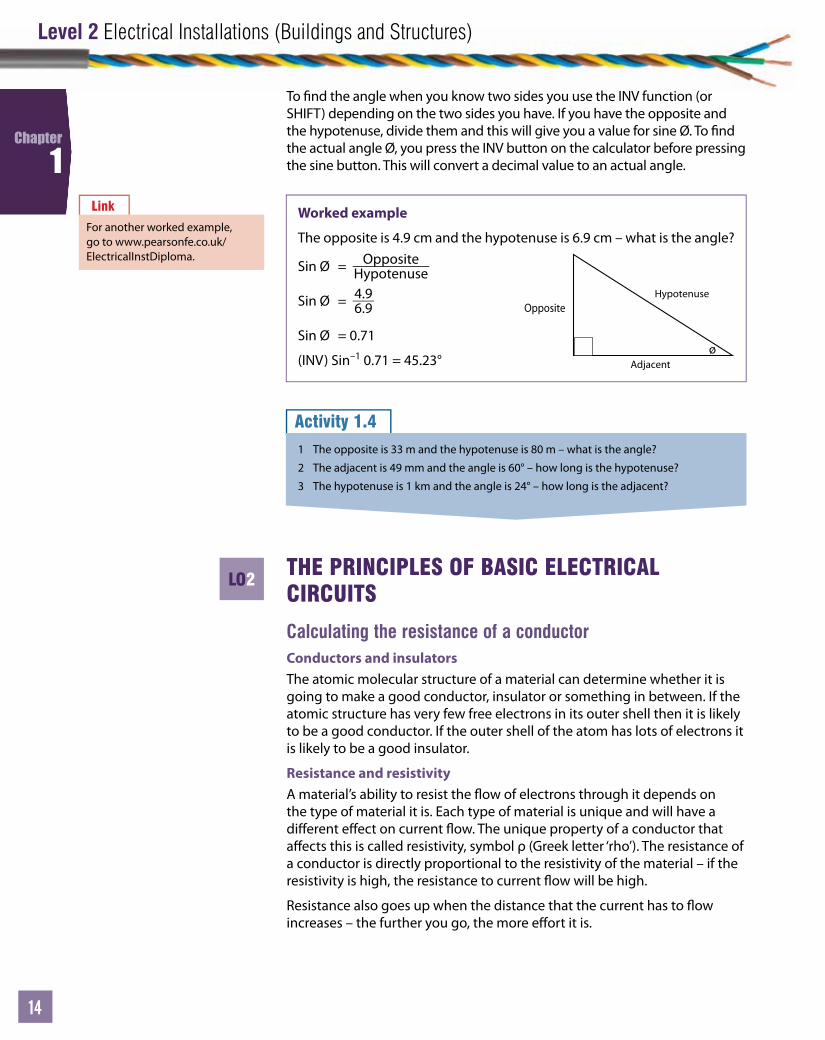
To nd the angle when you know two sides you use the INV function (or SHIFT) depending on the two sides you have. If you have the opposite and the hypotenuse, divide them and this will give you a value for sine Ø. To nd the actual angle Ø, you press the INV button on the calculator before pressing the sine button. This will convert a decimal value to an actual angle.
THE PRINCIPLES OF BASIC ELECTRICAL CIRCUITS
Calculating the resistance of a conductorConductors and insulatorsThe atomic molecular structure of a material can determine whether it is going to make a good conductor, insulator or something in between. If the atomic structure has very few free electrons in its outer shell then it is likely to be a good conductor. If the outer shell of the atom has lots of electrons it is likely to be a good insulator.
Resistance and resistivityA material’s ability to resist the ow of electrons through it depends on the type of material it is. Each type of material is unique and will have a di erent e ect on current ow. The unique property of a conductor that a ects this is called resistivity, symbol ρ (Greek letter ‘rho’). The resistance of a conductor is directly proportional to the resistivity of the material – if the resistivity is high, the resistance to current ow will be high.
Resistance also goes up when the distance that the current has to ow increases – the further you go, the more e ort it is.
Link
For another worked example, go to www.pearsonfe.co.uk/ElectricalInstDiploma.
Activity 1.41 The opposite is 33 m and the hypotenuse is 80 m – what is the angle?
2 The adjacent is 49 mm and the angle is 60° – how long is the hypotenuse?
3 The hypotenuse is 1 km and the angle is 24° – how long is the adjacent?
Worked example
The opposite is 4.9 cm and the hypotenuse is 6.9 cm – what is the angle?
Sin Ø = OppositeHypotenuse
Sin Ø = 4.96.9
Sin Ø = 0.71
(INV) Sin–1 0.71 = 45.23°
Opposite
Adjacent
Hypotenuse
ø
LO2

Unit
15
Chapter 1: Principles of electrical science
15
15
Chapter
1
To return to the water analogy – if there is a large pipe and a small pipe, it is much easier for water to ow in the large pipe. This is true for electricity and conductors. If there is a very thin conductor it will be more di cult for electrons to ow through it, as there are fewer atoms with free electrons available. A smaller cross-sectional area will reduce current ow and create a higher resistance. This means resistance is inversely proportional to cross-sectional area.
Given the resistivity, cross-sectional area and the length of a conductor, it is therefore possible to work out the resistance of any conductor. Putting all of these factors together in a formula gives:
R = ρIA
Link
For more worked examples, go to www.pearsonfe.co.uk/ElectricalInstDiploma.
Activity 1.5Work out the resistance of the following conductors:
1 a 25 m length of 2.5 mm2 copper
2 400 m of 1.5 mm2 copper
3 50 m of 8 mm2 aluminium
4 25 m of 6 mm2 copper
5 100 m of 1 mm2 copper earth conductor.
Worked example
Calculate the resistance of an aluminium cable of length 10 km and diameter 4 mm.
Firstly, convert all the units to the correct dimensions – never mix dimensions!
10 km = 10 × 103 (1 000 m in a km)
4 mm = 4 × 10⁻³ (1 000 mm in a m)
Resistivity, ρ, of aluminium is 28.2 × 10⁻⁹ (see Table 1.4 on page 16).
A = 14 πd2
A = 14 π(4 × 10⁻³)2
A = 14 π4 × 10–6 = 3.142 × 10⁻⁶
(Notice what happens with the powers inside and outside the brackets when they are combined.)
Using the formula R = ρIA , and replacing the symbols with the correct
numbers:
R = (28.2 × 10–9 × 10 × 103) (3.142 × 10⁻⁶)
R = 89.75 Ω
Level 2 Electrical Installations (Buildings and Structures)
16
Chapter
1
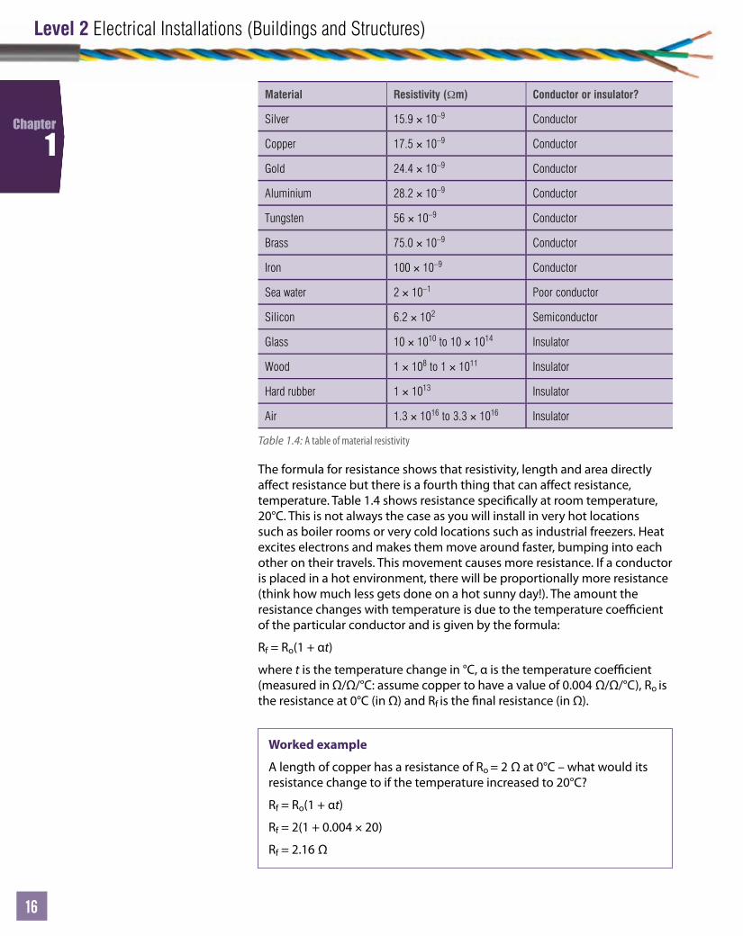
Material Resistivity (Ωm) Conductor or insulator?
Silver 15.9 × 10⁻⁹ Conductor
Copper 17.5 × 10⁻⁹ Conductor
Gold 24.4 × 10⁻⁹ Conductor
Aluminium 28.2 × 10⁻⁹ Conductor
Tungsten 56 × 10–9 Conductor
Brass 75.0 × 10⁻⁹ Conductor
Iron 100 × 10–9 Conductor
Sea water 2 × 10⁻¹ Poor conductor
Silicon 6.2 × 10² Semiconductor
Glass 10 × 1010 to 10 × 1014 Insulator
Wood 1 × 10⁸ to 1 × 10¹¹ Insulator
Hard rubber 1 × 10¹³ Insulator
Air 1.3 × 10¹⁶ to 3.3 × 10¹⁶ Insulator
Table 1.4: A table of material resistivity
The formula for resistance shows that resistivity, length and area directly a ect resistance but there is a fourth thing that can a ect resistance, temperature. Table 1.4 shows resistance speci cally at room temperature, 20°C. This is not always the case as you will install in very hot locations such as boiler rooms or very cold locations such as industrial freezers. Heat excites electrons and makes them move around faster, bumping into each other on their travels. This movement causes more resistance. If a conductor is placed in a hot environment, there will be proportionally more resistance (think how much less gets done on a hot sunny day!). The amount the resistance changes with temperature is due to the temperature coe cient of the particular conductor and is given by the formula:
Rf = Ro(1 + αt)
where t is the temperature change in °C, α is the temperature coe cient (measured in Ω/Ω/°C: assume copper to have a value of 0.004 Ω/Ω/°C), Ro is the resistance at 0°C (in Ω) and Rf is the nal resistance (in Ω).
Worked example
A length of copper has a resistance of Ro = 2 Ω at 0°C – what would its resistance change to if the temperature increased to 20°C?
Rf = Ro(1 + αt)
Rf = 2(1 + 0.004 × 20)
Rf = 2.16 Ω

Unit
17
Chapter 1: Principles of electrical science
17
17
Chapter
1
Applying Ohm’s lawA voltage source connected to a conductor to create a circuit will cause current to ow but conductors can be connected together in di erent ways.
Imagine two identical conductors are connected together end to end. Their length has now doubled. If they are identical, the overall resistance has also doubled because the free electrons travel twice as far and overcome twice the resistance. This is called a ‘series circuit’.
If the identical conductors are placed next to each other, there are two identical paths for the free electrons to ow down. This is a ‘parallel circuit’. Because there are two identical paths for the electrons to ow down, they split evenly and half will go down one route and the other half down the other route. The extra path means the overall resistance to electron ow in a parallel circuit such as this has halved. Consider the relationship between voltage pressure, current and the resistance of a conductor. All of these three points are reliant on each other. This relationship is described by Ohm’s law.
The current through a metallic conductor, maintained at constant temperature, is directly proportional to the potential di erence between its ends:
I α V
This means conductors that have a constant value for the ratio of VI must follow Ohm’s law:
R = VI
Consider a simple series circuit. If ‘R’ is constant and the voltage pressure increases, this means the current must also increase for the balance to continue. This is just like a tank of water with a tap at the bottom. Imagine the height of the water in the tank being the voltage pressure and the rate of ow of the water out of the tap being the current. As the water in the tank reduces, the ow reduces.
Figure 1.8: Water pressure in a tank – a water electricity analogy
H3 H3 H2 H1H2 H1
Level 2 Electrical Installations (Buildings and Structures)
18
Chapter
1
Calculating power in basic electrical circuitsResistance is mostly a constant value, and voltage and current can change. You have seen that the resistance of a conductor is based on conductor material, temperature, the cross-sectional area and length. All that needs to be discussed now is the e ect on resistance, current and voltage when you connect resistive conductors together in di erent ways.
Imagine the resistance of a conductor is measured using an ohmmeter and its value noted down. Now take a further identical conductor and connect the two ends to make it longer – you would expect the new ohm reading to be double. This is correct as you have created a conductive path twice as long for the electrons to travel along, hence double the resistance.
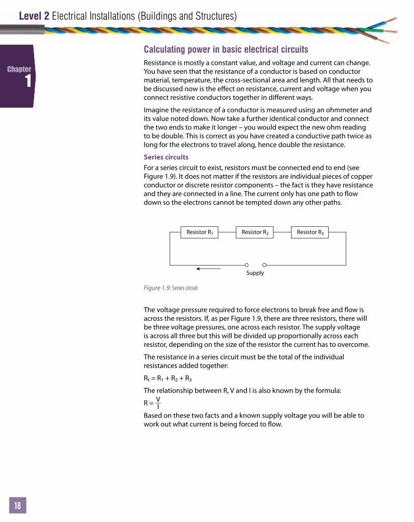
Series circuitsFor a series circuit to exist, resistors must be connected end to end (see Figure 1.9). It does not matter if the resistors are individual pieces of copper conductor or discrete resistor components – the fact is they have resistance and they are connected in a line. The current only has one path to ow down so the electrons cannot be tempted down any other paths.
The voltage pressure required to force electrons to break free and ow is across the resistors. If, as per Figure 1.9, there are three resistors, there will be three voltage pressures, one across each resistor. The supply voltage is across all three but this will be divided up proportionally across each resistor, depending on the size of the resistor the current has to overcome.
The resistance in a series circuit must be the total of the individual resistances added together:
Rt = R1 + R2 + R3
The relationship between R, V and I is also known by the formula:
R = VI
Based on these two facts and a known supply voltage you will be able to work out what current is being forced to ow.
Resistor R1 Resistor R2
Supply
Resistor R3
Figure 1.9: Series circuit
Unit
19
Chapter 1: Principles of electrical science
19
19
Chapter
1
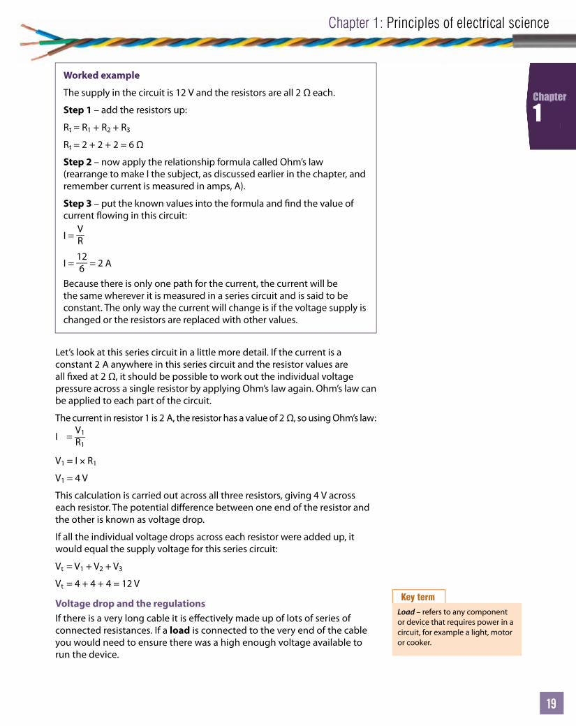
Let’s look at this series circuit in a little more detail. If the current is a constant 2 A anywhere in this series circuit and the resistor values are all xed at 2 Ω, it should be possible to work out the individual voltage pressure across a single resistor by applying Ohm’s law again. Ohm’s law can be applied to each part of the circuit.
The current in resistor 1 is 2 A, the resistor has a value of 2 Ω, so using Ohm’s law:
I = V1R1
V1 = I × R1
V1 = 4 V
This calculation is carried out across all three resistors, giving 4 V across each resistor. The potential di erence between one end of the resistor and the other is known as voltage drop.
If all the individual voltage drops across each resistor were added up, it would equal the supply voltage for this series circuit:
Vt = V1 + V2 + V3
Vt = 4 + 4 + 4 = 12 V
Voltage drop and the regulationsIf there is a very long cable it is e ectively made up of lots of series of connected resistances. If a load is connected to the very end of the cable you would need to ensure there was a high enough voltage available to run the device.
Worked example
The supply in the circuit is 12 V and the resistors are all 2 Ω each.
Step 1 – add the resistors up:
Rt = R1 + R2 + R3
Rt = 2 + 2 + 2 = 6 Ω
Step 2 – now apply the relationship formula called Ohm’s law (rearrange to make I the subject, as discussed earlier in the chapter, and remember current is measured in amps, A).
Step 3 – put the known values into the formula and nd the value of current owing in this circuit:
I = VR
I = 126 = 2 A
Because there is only one path for the current, the current will be the same wherever it is measured in a series circuit and is said to be constant. The only way the current will change is if the voltage supply is changed or the resistors are replaced with other values.
Key term
Load – refers to any component or device that requires power in a circuit, for example a light, motor or cooker.

Level 2 Electrical Installations (Buildings and Structures)
20
Chapter
1
Because of voltage drop in cables there is guidance given in BS 7671 (Electrical Installation Requirements, 17th edition).
BS 7671 states that lighting circuits should not exceed 3 per cent and power circuits should not exceed 5 per cent.
Safe working
All electrical circuits must be checked for voltage drop. If the voltage drop is greater than 3 per cent for lighting and 5 per cent for power, the circuit needs to be redesigned and will probably require a larger conductor.
! Activity 1.6For each of the ve examples below, calculate:
• the total resistance
• the total circuit current
• the voltage drop across each resistor.
1 A series circuit has three resistors: R1 = 3 Ω, R2 = 6 Ω, R3 = 9 Ω and is connected across a 12 V supply.
2 A series circuit has four resistors: R1 = 1.2 Ω, R2 = 2.6 Ω, R3 = 9 Ω, R4 = 9 Ω and is connected across a 24 V supply.
3 A series circuit has ve resistors: R1 = 12 Ω, R2 = 36 Ω, R3 = 29 Ω, R4 = 5 Ω, R5 = 6 Ω and is connected across a 36 V supply.
4 A series circuit has four resistors: R1 = 2 kΩ, R2 = 3 kΩ, R3 = 6.7 kΩ, R4 = 5 kΩ and is connected across a 230 V supply.
5 A series circuit has four resistors: R1 = 1.7 MΩ, R2 = 2.3 MΩ, R3 = 2.9 MΩ, R4 = 5.7 MΩ and is connected across a 400 V supply.
Parallel circuitsInstead of connecting the conductors end on to make one long resistive conductor, imagine connecting them side by side (see Figure 1.10).
In a parallel circuit the voltage source will push the electrons around until they reach a junction. At the junction the electrons have two choices – they now have two paths to travel down. Current is very lazy and will travel down the path of least resistance. If the paths were of equal resistance, an equal proportion of electrons would ow down each one – the resistance is e ectively halved. If there were three equal resistors or conductors connected in parallel (next to each other), then the overall resistance e ect would be one third, allowing the current to split into three equal parts. This is di erent to the series circuit where the current was constant. Now the voltage is a constant pressure as it is connected across the three resistances. The current is now the thing that varies as it leaves the source, splits into three at the junction, passes through each of the three resistors and then joins back together again at the other junction.
It = I1 + I2 + I3
With resistors in series it is straightforward to nd the overall e ect – simply add them up. Resistors in parallel need to be added up as fractions as we have seen; two identical resistors in parallel equate to half of one resistor and three identical resistors in parallel equate to one third of one resistor.
Resistor R1
I
Resistor R2
Figure 1.10: Parallel circuit
Key fact
In a parallel circuit, the current varies and the voltage is a constant.

Unit
21
Chapter 1: Principles of electrical science
21
21
Chapter
1
The relationship and calculation for parallel resistors is found by the following formula (three in this case):
1Rt
= 1R1
+ 1R2
1Rt
= R2 + R1R1 × R2
Rt1
= R2 × R1R1 + R2
Worked exampleNow consider R1 = 5 Ω and R2 = 7 Ω:1Rt
= 1R1
+ 1R2
1Rt
= now, put in the values:
Rt1 =
5 × 77 + 5
Rt = 3512
Rt = 2.92 ΩIf the supply voltage is 12 V, what is the total circuit current?The total resistance is 2.92Ω and the total supply voltage is 12 V, so apply Ohm’s law to nd the total circuit current:
I = VR
I = 12
2.92 = 4.1 A
If the total circuit current is 4.1 A and this is the value that leaves the supply travelling towards the junction between the two resistors – what happens when it reaches this junction? It splits – but how much goes down each branch? Apply Ohm’s law to each resistor to nd out.
Step 1 – the total current is 4.1 A and the total voltage ‘dropped across’ both resistors in parallel is 12 V. If the voltage across R1 (5 Ω) is 12 V, applying Ohm’s law to resistor R1 gives the following:
I1 = VR1
I1 = 125
= 2.4 A
Step 2 – now applying Ohm’s law to the other resistor, R2, gives the following:
I2 = VR2
I2 =
127
= 1.7 A
R2 + R1R1 × R2
Level 2 Electrical Installations (Buildings and Structures)
22
Chapter
1
Combined circuits – series and parallelAn electrical circuit may not be a simple series or parallel circuit. Electrical circuits may consist of a combination. The rule is to simplify wherever you can and remember you can always apply Ohm’s law to one single part of a
Step 3 – to prove the branch currents are correct, simply add them:
It = 2.4 + 1.7 = 4.1 A
Tip: always sketch out the circuit and label it as it will make the task quicker in the long run.
Activity 1.71 A parallel circuit consists of two resistors: R1 = 2.4 Ω and R2 = 1.2 Ω. If they are
connected to a 12 V supply, calculate:
(a) the total resistance (b) the total circuit current (c) the current in each resistor.
2 The circuit in Question 1 has a third resistor connected in parallel of 5.9 Ω. Carry out the same calculations and nd:
(a) the total resistance (b) the new total circuit current (c) the current in each of the three legs.
3 A parallel circuit consists of four resistors: R1 = 4 Ω, R2 = 1.8 Ω, R3 = 3.7 Ω and R2 = 6.7 Ω. If they are connected to a 24 V supply, calculate:
(a) the total resistance (b) the total circuit current (c) the current in each resistor.
4 The circuit in Question 3 has a fth resistor connected in parallel of 12.3 Ω and the voltage supply is changed to 40 V. Carry out the same calculations and nd:
(a) the total resistance (b) the new total circuit current (c) the current in each of the ve legs.
5 The circuit consists of four resistors connected in parallel. If R1 = 12 Ω, R2 = R1+20%, R3 = R2+20%, R4 = R3+20% and if the circuit is connected to a 36 V supply, calculate and nd:
(a) the individual resistor values (b) the total resistance (c) the total circuit current (d) the current in each of the four legs.
More than two parallel resistorsIf multiple resistors are connected in parallel, fractions can still be used to add them up. However, a much easier method is to use a scienti c calculator. The function is χ-1 . This function e ectively divides your resistor into 1, i.e. I
R. To add up three resistors, say 3 Ω each, follow the sequence:
3 χ-1 + 3 χ-1 +3 χ-1 =. All we have worked out so far is 1Rt
, so to nd Rt, press
χ-1 = again and you have your answer, 1, as expected.
Unit
23
Chapter 1: Principles of electrical science
23
23
Chapter
1
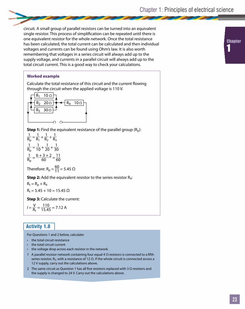
Worked example
Calculate the total resistance of this circuit and the current owing through the circuit when the applied voltage is 110 V.
R1 10 Ω
R2 20 Ω R4 10 Ω
R3 30 Ω
Step 1: Find the equivalent resistance of the parallel group (Rp):1
Rp = 1
R1 + 1
R2 + 1
R3
1Rp
= 110 + 1
20 + 130
1Rp
= 6 + 3 + 260 = 11
60
Therefore: Rp = 6011 = 5.45 Ω
Step 2: Add the equivalent resistor to the series resistor R4:Rt = Rp + R4
Rt = 5.45 + 10 = 15.45 Ω
Step 3: Calculate the current:
I = VRt
= 11015.45 = 7.12 A
circuit. A small group of parallel resistors can be turned into an equivalent single resistor. This process of simpli cation can be repeated until there is one equivalent resistor for the whole network. Once the total resistance has been calculated, the total current can be calculated and then individual voltages and currents can be found using Ohm’s law. It is also worth remembering that voltages in a series circuit will always add up to the supply voltage, and currents in a parallel circuit will always add up to the total circuit current. This is a good way to check your calculations.
Activity 1.8For Questions 1 and 2 below, calculate:
• the total circuit resistance• the total circuit current• the voltage drop across each resistor in the network.
1 A parallel resistor network containing four equal 4 Ω resistors is connected to a fth series resistor, R5, with a resistance of 12 Ω. If the whole circuit is connected across a 12 V supply, carry out the calculations above.
2 The same circuit as Question 1 has all ve resistors replaced with 3 Ω resistors and the supply is changed to 24 V. Carry out the calculations above.
Level 2 Electrical Installations (Buildings and Structures)
24
Chapter
1
Power in a circuitPower is de ned as the rate at which work is done. Clearly, when an electron is forced free from an atom and pushed around a circuit, work must have been done. Power is also the heating e ect of passing a current through a conductor – you probably have a heater at home that has a power rating written on it somewhere. The power rating describes how much heat can be expected – the higher the power rating, the higher the heating e ect.
The basic power formula for a circuit with a known voltage and current is given by the following:
P = I × V
Ohm’s law can be used to give another power formula:
V = I × R
The Ohm’s law formula for V can be put into the power formula:
P = I × (I × R)
P = I2 × R
By rearranging Ohm’s law again to make ‘I’ the subject, you can put this into the power formula to get a third formula for power as follows:
I = VR
P = ( VR ) × V
P = V2
R
Worked example
A resistor has a current of 20 mA passing through it when a voltage supply of 200 V is connected across it. What is the power?
P = V × I
P = 200 × 20 × 10–3
P = 4 W
Link
For more worked examples, go to www.pearsonfe.co.uk/ElectricalInstDiploma.
Activity 1.91 Calculate the power if a 100 mΩ resistor is connected to a 36 V supply.
2 What is the resistor value if the power is 10.2 W when a current of 3.9 A passes through it?
3 If the voltage across a 1.2 kΩ resistor is 210 V, what is the power dissipated?
4 A voltmeter registers 125 V across a resistor and an ammeter reads 30 A. What is the power dissipated in the resistor?
5 What is the voltage drop across a 15 Ω resistor when the power measures 120 W?
Unit
25
Chapter 1: Principles of electrical science
25
25
Chapter
1
How instruments are connected in circuits in order to measure electrical quantitiesThe majority of tests (except resistance tests) are all live. For this reason great care must be taken and all guidance followed. The use of test instruments is where science and practical skills come together.
Some very important electrical terms and principles have been established. Firstly, electrons move from one ion to another causing the e ect ‘current ow’. The statement ‘current ows through a conductor’ is therefore a fact worth remembering. Secondly, the potential di erence that exists from one side of an electrical circuit to the other side is the pressure responsible for encouraging the current ow. The statement ‘potential di erence is measured across a circuit or a load’ is also well worth remembering.
Before the meter is connectedThere are a few things that need to be considered before connecting a meter to a circuit. Unfortunately electricians do get electric shocks and a number of accidents actually occur at the testing stage. You need to be sure of the following:
1 Am I quali ed to use this meter?
2 Do I have the correct meter for the job?
3 Do the instruments, leads, probes and accessories meet the Health and Safety Guidance Note GS38 standards?
4 Is it damage-free and working correctly, and how can I prove this?
5 How do I know what to set it on and how does it work?
6 What am I trying to test and therefore how is it connected?
Once all of these points have been answered, you should be able to go to the next step and choose your meter for the test.
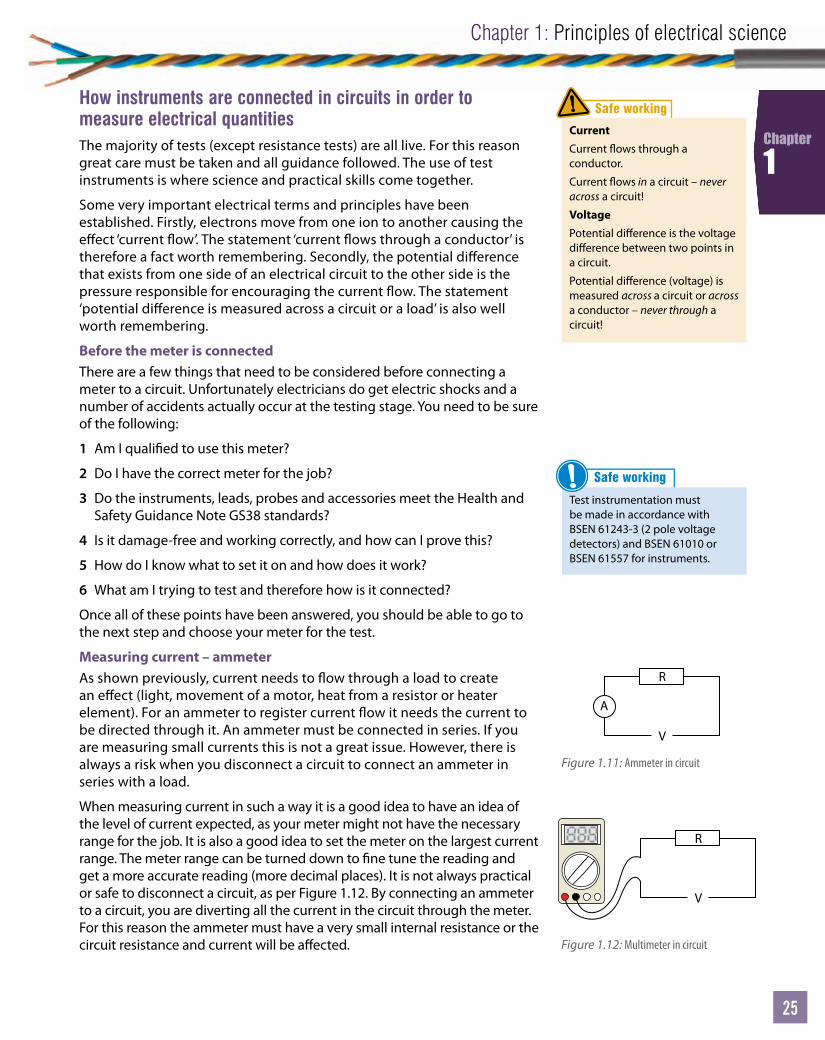
Measuring current – ammeterAs shown previously, current needs to ow through a load to create an e ect (light, movement of a motor, heat from a resistor or heater element). For an ammeter to register current ow it needs the current to be directed through it. An ammeter must be connected in series. If you are measuring small currents this is not a great issue. However, there is always a risk when you disconnect a circuit to connect an ammeter in series with a load.
When measuring current in such a way it is a good idea to have an idea of the level of current expected, as your meter might not have the necessary range for the job. It is also a good idea to set the meter on the largest current range. The meter range can be turned down to ne tune the reading and get a more accurate reading (more decimal places). It is not always practical or safe to disconnect a circuit, as per Figure 1.12. By connecting an ammeter to a circuit, you are diverting all the current in the circuit through the meter. For this reason the ammeter must have a very small internal resistance or the circuit resistance and current will be a ected.
Safe working
Current
Current ows through a conductor.
Current ows in a circuit – never across a circuit!
VoltagePotential di erence is the voltage di erence between two points in a circuit.
Potential di erence (voltage) is measured across a circuit or across a conductor – never through a circuit!
!
V
R
A
V
R
V
R
A
V
R
Figure 1.11: Ammeter in circuit
Figure 1.12: Multimeter in circuit
Safe working
Test instrumentation must be made in accordance with BSEN 61243-3 (2 pole voltage detectors) and BSEN 61010 or BSEN 61557 for instruments.
!

Level 2 Electrical Installations (Buildings and Structures)
26
Chapter
1
Measuring large currentsBreaking a circuit that is carrying 100 A to connect a series ammeter would be very unwise. If you are lucky enough to live, it will be an extremely frightening experience! If the circuit is safely isolated, the meter and connecting clips must still be able to take the largest current – this is still to be avoided. By using the principle of magnetic induction and clamp meters the circuit can stay connected without having to actually become part of the electrical circuit. It should be noted that it is still very dangerous with such high levels of current so all the normal precautions must be taken, as well as checking the meter for damage before and after use.
As current ows through the conductor, a magnetic eld is generated. If a further coil is placed around the current-carrying conductor, this magnetic eld can be picked up. The magnetic eld will cut the conductors in the secondary coil and induce a further current that will travel through the meter. The value of current travelling through the meter can be stepped down so the value can be read easily. The main supply cable is acting like the primary side of a transformer and the meter clamp coils are acting like the secondary side of a transformer. This is why this type of arrangement is sometimes called a CT or current transformer. There is no actual electrical contact between the supply cable and the clamp meter – all the current being measured is induced by magnetism. The current and voltage levels in the clamp meter are still extremely high and dangerous, and great care should be taken to short the CT out before trying to move the meter. (The science of transformers will be covered later.) A CT meter may be used if you were measuring a 400 V 100 A supply with a clamp meter. Within the CT meter the current may be stepped down so it is in the 0–10 A range. This would mean you could have at the terminals of your clamp meter 4000 V at 10 A – enough to kill you several times over!
Measuring voltage – voltmeterVoltage pressure supplies the driving force to cause current ow. A potential di erence will exist across a load to make the electrons pass through the load. A voltmeter is therefore connected across a load in order to get a reading. See Figures 1.14 and 1.15 below for connections.
Safe working
Never break into a live circuit to connect a series ammeter – the result could be fatal. Only in speci c circumstances will highly trained electricians with special permission work live.
Figure 1.13: Clamp meter measuring a large current
V
R
V
V
R
Figure 1.14: Voltmeter in circuit
V
R
V
V
R
Figure 1.15: Multimeter measuring voltage

Unit
27
Chapter 1: Principles of electrical science
27
27
Chapter
1
Supply cable,large voltage
Primarycoil
Secondarycoil
V
Figure 1.16: Voltage transformer to measure large supply voltages
Resistance under test
Instrument
Figure 1.17: Ohmmeter
Whereas the ammeter has a very low internal resistance to encourage current to ow through it, the voltmeter has a very high resistance. To measure voltage as accurately as possible, most of the current should continue owing through the load and only a very small proportion of current should pass through the voltmeter. There will always be a small error introduced by using a voltmeter or ammeter as you are adding components to the circuit you are measuring, but these can be minimised by careful calibration.
Measuring large voltagesLarge voltages exist on the national grid and in large industrial sites and buildings. It is not wise to try and take live readings using a standard meter, even if it does have the range. Large installations often have voltage and current meters built in to the control panels so they can be monitored constantly or at a glance. Using the same magnetic transformer principles as the CT meter, large voltages can be measured safely. A large supply voltage cable will have a secondary coil on a transformer to step the voltage down to an acceptable level for metering equipment. As you will nd out in the next section, stepping a voltage down will have the opposite e ect on current and step it up.
Measuring resistance – ohmmeterTo measure the resistance of a circuit, it must be dead and safely isolated. Resistance is found by applying Ohm’s law. The ohmmeter is essentially a combined ammeter and voltmeter.
R = VI
If the voltage is known, the internal battery supply of the meter and the current can be measured by the ammeter, then Ohm’s law can be applied. The ohmmeter connects the meter battery across the load to be measured. The current that ows around the circuit is dependent on the resistor. The meter divides the battery voltage by the current owing and gives the resultant value for resistance. Care has to be taken to make sure any extra resistance introduced by the test leads is taken into account. The lead resistance can be measured by touching the probes together and then making a note that this needs to be taken o the nal reading. Most modern meters have a built ‘null’ facility. By pushing the null button while holding the probes/crocodile clips together, the meter display will return to zero and is ready to be reconnected to the circuit to be tested.
Measuring power quantities – wattmeterIn the same way that an ohmmeter uses the combination of voltage meter and ammeter, the wattmeter can follow the same principle to measure power in watts. For a d.c. circuit, power can be measured by taking a voltmeter and ammeter reading and then multiplying together:
P = V × I

Level 2 Electrical Installations (Buildings and Structures)
28
Chapter
1
In the a.c. world this is not as straightforward as there are other things to consider such as capacitance, inductance and impedance – these are reactions to a.c. current that will be covered later in the chapter. These reactive components have a slightly di erent e ect on the current if compared to just resistance, and need to be taken into account. For this reason a.c. single-phase power is measured using the same formula as above but is also multiplied by a ‘power factor’ as follows:
P = V × I × (Power factor)
P = VI cos Ø
A full description of the ‘types of power’ will be expanded on in a later chapter but at this stage it can be considered as a decimal multiplier that is a value less than 1 (1 being perfect). Power factor at this stage can also be considered as a power e ciency multiplier that needs to be considered in all a.c. circuits that contain a capacitor or coil (power factor will be covered fully later on in this chapter). You will need to measure the true power being consumed in a circuit which is why a specially connected wattmeter is required. The wattmeter usually has four terminals – two for the voltage coil and two for the current coil, as shown in Figure 1.18.
Measuring three-phase power quantitiesIf a single-phase supply can be measured in the way just described, then so can one phase on a three-phase supply, in theory. This can only happen if all the phases are balanced – drawing the same current and at the same voltage level. If the three phases are balanced, thenthe reading for one phase can be simply multiplied by three to give the total power. The wattmeter would be connected, as shown in Figure 1.19 below. You would only take a power reading like this if the three phases were balanced, otherwise there could be errors.
Load
W1 W2
P2
P1
Figure 1.18: Wattmeter connected to load
Br
Gy
Bu
Bl
W1 W2
Wattmeter
P1 P2
Figure 1.19: One-meter method
True power in a balanced three-phase supply = Voltage × current × power factor
The following equation shows the balanced power/current across the supply:
P = √ 3 VL IL cos Ø
Unit
29
Chapter 1: Principles of electrical science
29
29
Chapter
1
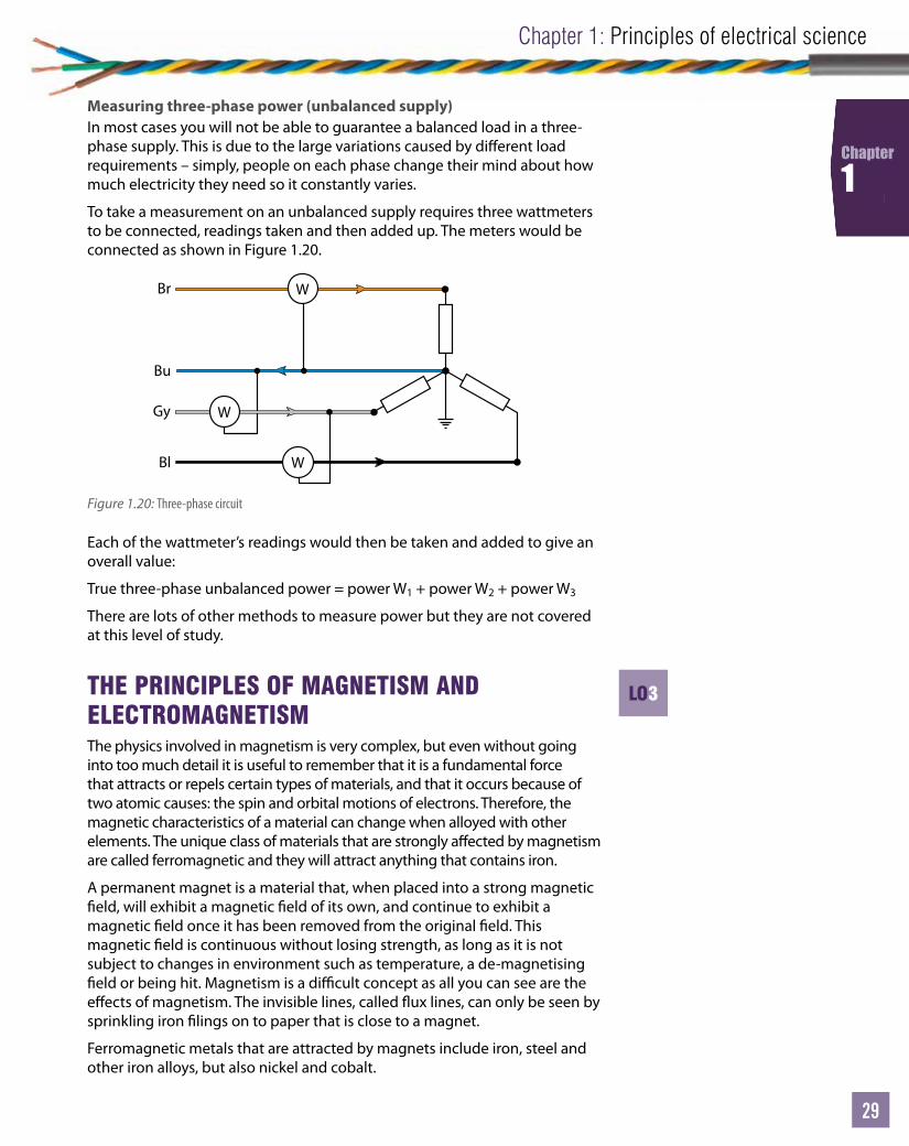
Each of the wattmeter’s readings would then be taken and added to give an overall value:
True three-phase unbalanced power = power W1 + power W2 + power W3
There are lots of other methods to measure power but they are not covered at this level of study.
THE PRINCIPLES OF MAGNETISM AND ELECTROMAGNETISMThe physics involved in magnetism is very complex, but even without going into too much detail it is useful to remember that it is a fundamental force that attracts or repels certain types of materials, and that it occurs because of two atomic causes: the spin and orbital motions of electrons. Therefore, the magnetic characteristics of a material can change when alloyed with other elements. The unique class of materials that are strongly a ected by magnetism are called ferromagnetic and they will attract anything that contains iron.
A permanent magnet is a material that, when placed into a strong magnetic eld, will exhibit a magnetic eld of its own, and continue to exhibit a magnetic eld once it has been removed from the original eld. This magnetic eld is continuous without losing strength, as long as it is not subject to changes in environment such as temperature, a de-magnetising eld or being hit. Magnetism is a di cult concept as all you can see are the e ects of magnetism. The invisible lines, called ux lines, can only be seen by sprinkling iron lings on to paper that is close to a magnet.
Ferromagnetic metals that are attracted by magnets include iron, steel and other iron alloys, but also nickel and cobalt.
Measuring three-phase power (unbalanced supply)In most cases you will not be able to guarantee a balanced load in a three-phase supply. This is due to the large variations caused by di erent load requirements – simply, people on each phase change their mind about how much electricity they need so it constantly varies.
To take a measurement on an unbalanced supply requires three wattmeters to be connected, readings taken and then added up. The meters would be connected as shown in Figure 1.20.
Br
Gy
Bu
Bl W
W
W
Figure 1.20: Three-phase circuit
LO3
Level 2 Electrical Installations (Buildings and Structures)
30
Chapter
1
Magnetic materials and applicationsIf you moved a ferromagnetic material such as a pin close to a permanent magnet, the pin would be strongly attracted to the magnet.
• So magnetic e ect can happen at a distance.
The pin is not initially magnetised but magnetic properties are induced into the pin.
• Magnetic induction never causes repulsion.
The material that the pin is made out of will determine if the pin stays magnetised long after it is removed from the permanent magnet. Some materials will stay magnetised, while others will lose it fairly quickly:
• Soft magnetic materials like stalloy, a soft iron alloy, can be magnetised and demagnetised easily. Typically, they are used in transformer cores and electromagnets.
• Hard magnetic materials like alnico and alcomax are very hard and can be made into very strong permanent magnets.
Rules of magnetismThere are several features that magnets display:
• Magnets have two poles, North and South.• The magnetic lines of force ( ux) never cross.• Flux lines always form a closed loop.• If the ux lines distort when brought close to another magnetic eld
they will always return to their original shape when moved away again.• Outside of the magnet, ux lines run North to South.• A magnet placed in a magnetic eld experiences a force on it.• The higher the concentration of ux lines, the stronger the magnet.• Like poles repel.• Unlike poles attract.
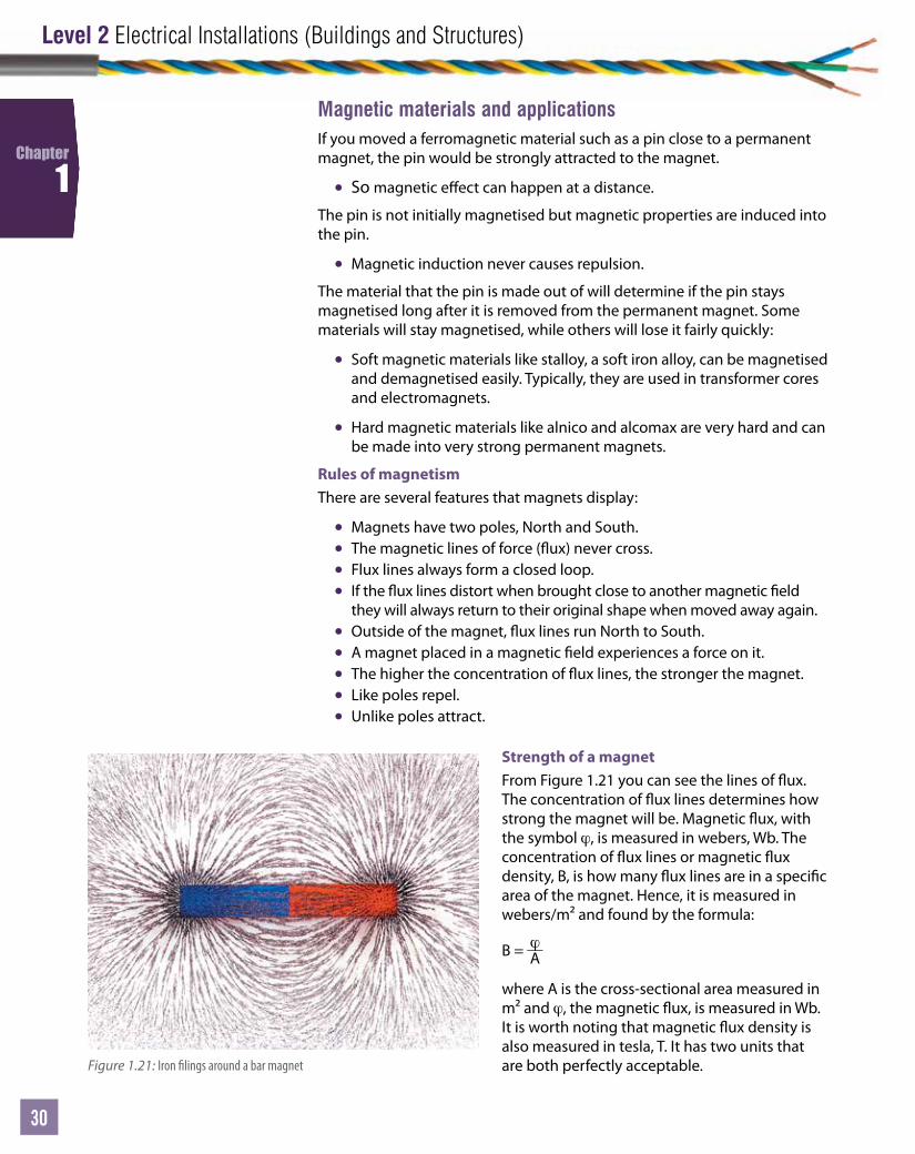
Figure 1.21: Iron lings around a bar magnet
Strength of a magnetFrom Figure 1.21 you can see the lines of ux. The concentration of ux lines determines how strong the magnet will be. Magnetic ux, with the symbol ϕ, is measured in webers, Wb. The concentration of ux lines or magnetic ux density, B, is how many ux lines are in a speci c area of the magnet. Hence, it is measured in webers/m² and found by the formula:
B = ϕA
where A is the cross-sectional area measured in m² and ϕ, the magnetic ux, is measured in Wb. It is worth noting that magnetic ux density is also measured in tesla, T. It has two units that are both perfectly acceptable.

Unit
31
Chapter 1: Principles of electrical science
31
31
Chapter
1
ElectromagnetismWhen current passes through a conductor, a magnetic eld is induced around that conductor. The strength of the magnetic eld is proportional to the amount of current passing through the conductor. It can only exist while the current is owing. Control of an electromagnet can be achieved by simply putting a switch into the circuit.
It is important for lots of applications to know the direction in which the magnetic eld is going. Motor movement is caused by the interaction of magnetic elds, so it is a good idea to know which way the motor will start spinning. The concentric circles of magnetic ux lines stretch along the whole length of a current-carrying conductor and the ux direction is relative to the direction of current, as can be seen in Figure 1.22.
Maxwell’s screw ruleAn easy way to work out which way the ux lines are running is to imagine putting a screw into a piece of wood. As the screw is turning clockwise it is going into the wood. The direction of the screw is the direction of the current ow (away from you and into the wood) and the clockwise rotation represents the rotation of ux lines, as per Figure 1.23 below. This is known as Maxwell’s screw rule and is named after the scientist who discovered it.
Worked example 1
Calculate the magnetic ux density of a magnet with a ux 2 Wb and cross-sectional area of 0.13 m².
B = ϕA
B = 20.13 = 15.38
Link
For more worked examples, go to www.pearsonfe.co.uk/ElectricalInstDiploma.
Activity 1.101 What cross-sectional area does a magnet need to have to produce a magnetic ux
density of 5 T when the magnetic ux is 5 Wb?2 What is the magnetic ux density of a magnet with a cross-sectional area of 0.3 m²
and a ux of 4 Wb?3 What is the magnetic ux of a 160 mT magnet with a cross-sectional area of 200 mm²?4 A magnet of ux 120 μWb and cross-sectional area 200 mm2 is required to have a
ux density of 1 T to be used as a re door magnet. Is this magnet strong enough to hold the re door open?
5 A motor requires a magnet with a ux density of 0.65 T. If the ux is 200 mWb, what is the cross-sectional area of the magnet?
Rotation of screw = Rotation of magnetic field
Direction of screw = Direction of current
Direction ofcurrent
Directionof flux
Figure 1.22: Lines of magnetic force set up around a conductor
Figure 1.23: The screw rule
Level 2 Electrical Installations (Buildings and Structures)
32
Chapter
1
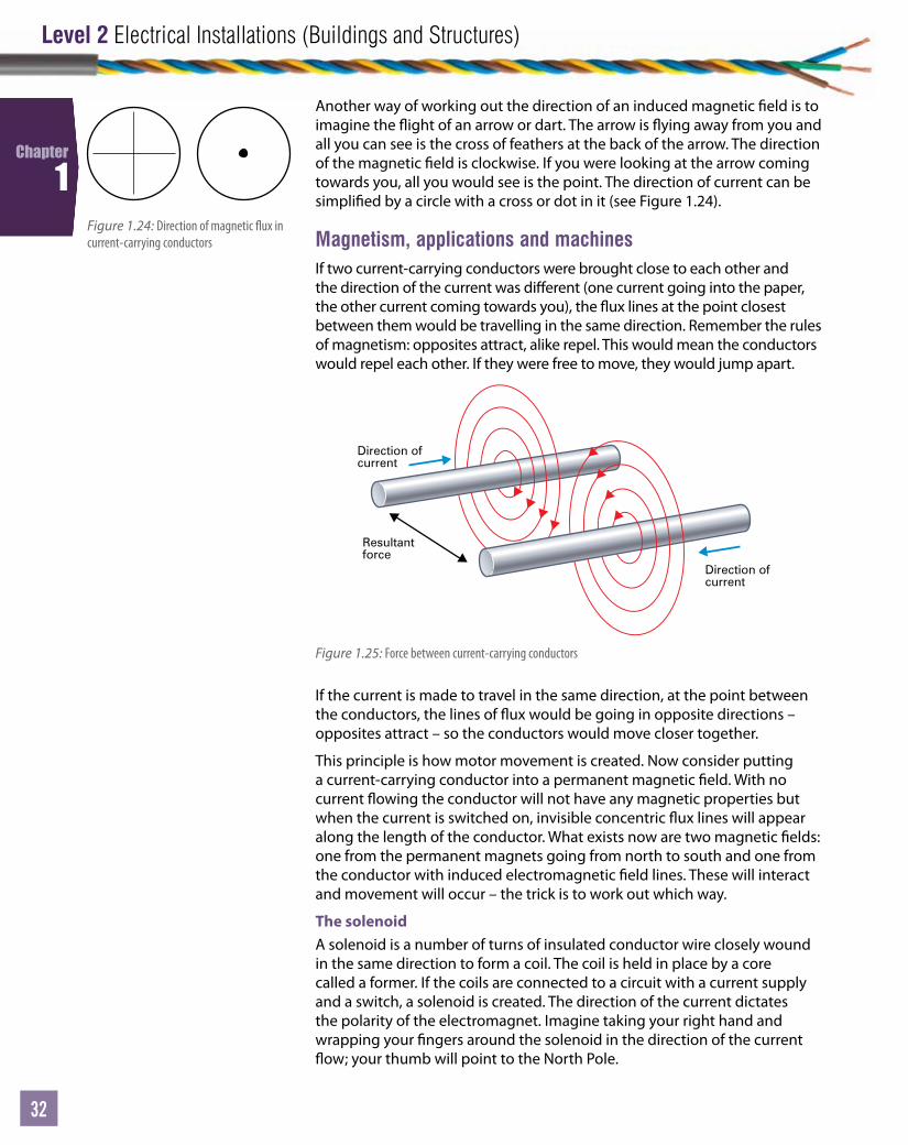
Another way of working out the direction of an induced magnetic eld is to imagine the ight of an arrow or dart. The arrow is ying away from you and all you can see is the cross of feathers at the back of the arrow. The direction of the magnetic eld is clockwise. If you were looking at the arrow coming towards you, all you would see is the point. The direction of current can be simpli ed by a circle with a cross or dot in it (see Figure 1.24).
Magnetism, applications and machinesIf two current-carrying conductors were brought close to each other and the direction of the current was di erent (one current going into the paper, the other current coming towards you), the ux lines at the point closest between them would be travelling in the same direction. Remember the rules of magnetism: opposites attract, alike repel. This would mean the conductors would repel each other. If they were free to move, they would jump apart.
Figure 1.24: Direction of magnetic ux in current-carrying conductors
If the current is made to travel in the same direction, at the point between the conductors, the lines of ux would be going in opposite directions – opposites attract – so the conductors would move closer together.
This principle is how motor movement is created. Now consider putting a current-carrying conductor into a permanent magnetic eld. With no current owing the conductor will not have any magnetic properties but when the current is switched on, invisible concentric ux lines will appear along the length of the conductor. What exists now are two magnetic elds: one from the permanent magnets going from north to south and one from the conductor with induced electromagnetic eld lines. These will interact and movement will occur – the trick is to work out which way.
The solenoidA solenoid is a number of turns of insulated conductor wire closely wound in the same direction to form a coil. The coil is held in place by a core called a former. If the coils are connected to a circuit with a current supply and a switch, a solenoid is created. The direction of the current dictates the polarity of the electromagnet. Imagine taking your right hand and wrapping your ngers around the solenoid in the direction of the current ow; your thumb will point to the North Pole.
Resultantforce
Direction ofcurrent
Direction ofcurrent
Figure 1.25: Force between current-carrying conductors
Unit
33
Chapter 1: Principles of electrical science
33
33
Chapter
1
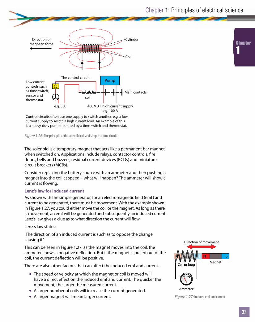
The solenoid is a temporary magnet that acts like a permanent bar magnet when switched on. Applications include relays, contactor controls, re doors, bells and buzzers, residual current devices (RCDs) and miniature circuit breakers (MCBs).
Consider replacing the battery source with an ammeter and then pushing a magnet into the coil at speed – what will happen? The ammeter will show a current is owing.
Lenz’s law for induced currentAs shown with the simple generator, for an electromagnetic eld (emf) and current to be generated, there must be movement. With the example shown in Figure 1.27, you could either move the coil or the magnet. As long as there is movement, an emf will be generated and subsequently an induced current. Lenz’s law gives a clue as to what direction the current will ow.
Lenz’s law states:
‘The direction of an induced current is such as to oppose the change causing it.’
This can be seen in Figure 1.27: as the magnet moves into the coil, the ammeter shows a negative de ection. But if the magnet is pulled out of the coil, the current de ection will be positive.
There are also other factors that can a ect the induced emf and current.
• The speed or velocity at which the magnet or coil is moved will have a direct e ect on the induced emf and current. The quicker the movement, the larger the measured current.
• A larger number of coils will increase the current generated.• A larger magnet will mean larger current.
Direction ofmagnetic force
Cylinder
Coil
400 V 3 F high current supplye.g. 100 A
e.g. 5 A
Control circuits often use one supply to switch another, e.g. a lowcurrent supply to switch a high current load. An example of thisis a heavy-duty pump operated by a time switch and thermostat.
Low currentcontrols suchas time switch,sensor andthermostat
Main contacts
The control circuit
coil
Pump
Figure 1.26: The principle of the solenoid coil and simple control circuit
NNNN S N S
Coil or loopMagnet
Ammeter
0+–
Coil or loop
Ammeter
0+–
Direction of movement
Figure 1.27: Induced emf and current
Level 2 Electrical Installations (Buildings and Structures)
34
Chapter
1
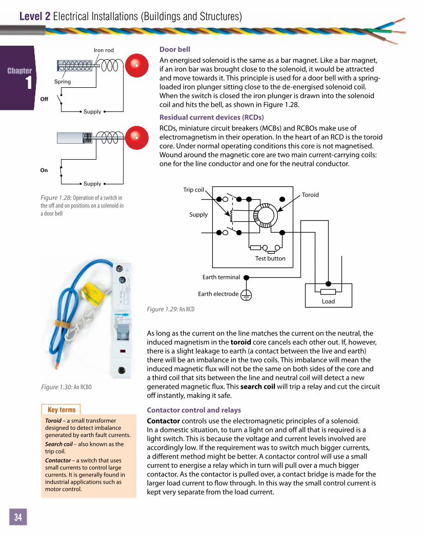
Door bellAn energised solenoid is the same as a bar magnet. Like a bar magnet, if an iron bar was brought close to the solenoid, it would be attracted and move towards it. This principle is used for a door bell with a spring-loaded iron plunger sitting close to the de-energised solenoid coil. When the switch is closed the iron plunger is drawn into the solenoid coil and hits the bell, as shown in Figure 1.28.
Residual current devices (RCDs)RCDs, miniature circuit breakers (MCBs) and RCBOs make use of electromagnetism in their operation. In the heart of an RCD is the toroid core. Under normal operating conditions this core is not magnetised. Wound around the magnetic core are two main current-carrying coils: one for the line conductor and one for the neutral conductor.
As long as the current on the line matches the current on the neutral, the induced magnetism in the toroid core cancels each other out. If, however, there is a slight leakage to earth (a contact between the live and earth) there will be an imbalance in the two coils. This imbalance will mean the induced magnetic ux will not be the same on both sides of the core and a third coil that sits between the line and neutral coil will detect a new generated magnetic ux. This search coil will trip a relay and cut the circuit o instantly, making it safe.
Contactor control and relaysContactor controls use the electromagnetic principles of a solenoid. In a domestic situation, to turn a light on and o all that is required is a light switch. This is because the voltage and current levels involved are accordingly low. If the requirement was to switch much bigger currents, a di erent method might be better. A contactor control will use a small current to energise a relay which in turn will pull over a much bigger contactor. As the contactor is pulled over, a contact bridge is made for the larger load current to ow through. In this way the small control current is kept very separate from the load current.
Figure 1.28: Operation of a switch in the o and on positions on a solenoid in a door bell
Toroid
Load
Earth terminal
Earth electrode
Trip coil
Supply
Test button
Figure 1.29: An RCD
Figure 1.30: An RCBO
Key terms
Toroid – a small transformer designed to detect imbalance generated by earth fault currents.Search coil – also known as the trip coil.Contactor – a switch that uses small currents to control large currents. It is generally found in industrial applications such as motor control.
Supply
Iron rod
Spring
Supply
Off
On

Unit
35
Chapter 1: Principles of electrical science
35
35
Chapter
1
In Figure 1.32 it can be seen under normal conditions the switch is open and is termed ‘normally open’. When the coil in the relay is energised the light is switched on. Contactor relays can be con gured in many di erent ways but remember contactors are still only simple switches and if you can follow a wiring diagram you will be able to wire a contactor.
Force on a conductorA current-carrying conductor will move with a certain force when placed in a magnetic eld. The force on a conductor is directly related to three things:
• the strength of the magnet (magnetic ux density or concentration of ux lines)
• the amount of current you pass through the conductor• the length of the conductor that you put between the
permanent magnetic poles.
The formula for force on a conductor is as follows:
Force, F = B × I × L
where F is force in newtons, B is magnetic ux density in Wb/m² or tesla, I is the current in amps and L is length in metres.
Current is often in mA and magnetic ux density is often in mWb/m², so be careful and convert rst before trying calculations.
To try and remember this equation think of ‘ForcefulBill’ or ‘Bill was not a nice man, he was very forceful’.
Figure 1.31: A relay
Coil Figure 1.32: One-way switch – o position
Coil Figure 1.33: One-way switch – on position
Worked example
A 3 m conductor is placed in a magnetic eld of 3 T when a current of 3 A is turned on. What force is exerted on the conductor?
F = B × I × L
F = 3 × 3 × 3 = 27 N
Link
For more worked examples, go to www.pearsonfe.co.uk/ElectricalInstDiploma.
Activity 1.111 Calculate how long a conductor is when placed inside a 4 T magnetic pole pair.
A force of 6 N is experienced when the current is 20.9 mA.
2 What force will a 0.6 m conductor experience if it has a 3 mA current owing through it and is placed in a 5 T magnetic ux?
3 Calculate the magnetic ux density of a 22 m current-carrying conductor that is carrying a current of 2 A and experiences a force of 3 N.
4 What current is owing in a conductive armature of 0.3 m length when it experiences a force of 0.68 N when moving through a 2 T magnetic eld?
5 How long does a conductor need to be to experience a force of 3 N when a current of 250 mA passes through it? The magnetic ux density is 350 mT.
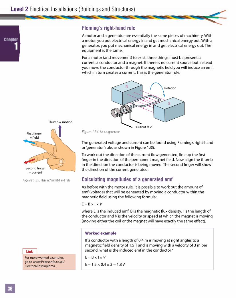
Level 2 Electrical Installations (Buildings and Structures)
36
Chapter
1
Fleming’s right-hand ruleA motor and a generator are essentially the same pieces of machinery. With a motor, you put electrical energy in and get mechanical energy out. With a generator, you put mechanical energy in and get electrical energy out. The equipment is the same.
For a motor (and movement) to exist, three things must be present: a current, a conductor and a magnet. If there is no current source but instead you move the conductor through the magnetic eld you will induce an emf, which in turn creates a current. This is the generator rule.
Rotation
Output (a.c.)
N
S
Figure 1.34: An a.c. generator
Thumb = motion
First nger= eld
Second nger= current
Figure 1.35: Fleming’s right-hand rule
The generated voltage and current can be found using Fleming’s right-hand or ‘generator’ rule, as shown in Figure 1.35.
To work out the direction of the current ow generated, line up the rst nger in the direction of the permanent magnet eld. Now align the thumb in the direction the conductor is being moved. The second nger will show the direction of the current generated.
Calculating magnitudes of a generated emfAs before with the motor rule, it is possible to work out the amount of emf (voltage) that will be generated by moving a conductor within the magnetic eld using the following formula:
E = B × I × V
where E is the induced emf, B is the magnetic ux density, l is the length of the conductor and V is the velocity or speed at which the magnet is moving (moving either the coil or the magnet will have exactly the same e ect).
Worked example
If a conductor with a length of 0.4 m is moving at right angles to a magnetic eld density of 1.5 T and is moving with a velocity of 3 m per second, what is the induced emf in the conductor?
E = B × I × V
E = 1.5 × 0.4 × 3 = 1.8 V
Link
For more worked examples, go to www.Pearsonfe.co.uk/ElectricalInstDiploma.
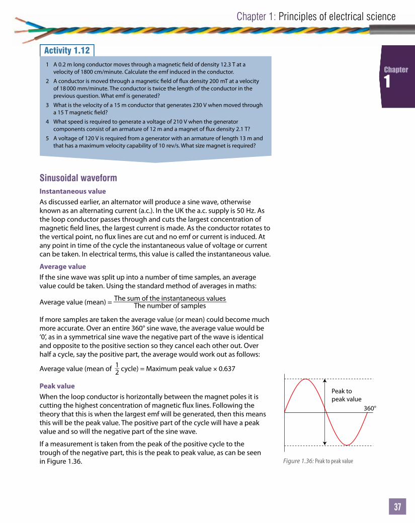
Unit
37
Chapter 1: Principles of electrical science
37
37
Chapter
1
Sinusoidal waveformInstantaneous valueAs discussed earlier, an alternator will produce a sine wave, otherwise known as an alternating current (a.c.). In the UK the a.c. supply is 50 Hz. As the loop conductor passes through and cuts the largest concentration of magnetic eld lines, the largest current is made. As the conductor rotates to the vertical point, no ux lines are cut and no emf or current is induced. At any point in time of the cycle the instantaneous value of voltage or current can be taken. In electrical terms, this value is called the instantaneous value.
Average valueIf the sine wave was split up into a number of time samples, an average value could be taken. Using the standard method of averages in maths:
Average value (mean) = The sum of the instantaneous valuesThe number of samples
If more samples are taken the average value (or mean) could become much more accurate. Over an entire 360° sine wave, the average value would be ‘0’, as in a symmetrical sine wave the negative part of the wave is identical and opposite to the positive section so they cancel each other out. Over half a cycle, say the positive part, the average would work out as follows:
Average value (mean of 12 cycle) = Maximum peak value × 0.637
Peak valueWhen the loop conductor is horizontally between the magnet poles it is cutting the highest concentration of magnetic ux lines. Following the theory that this is when the largest emf will be generated, then this means this will be the peak value. The positive part of the cycle will have a peak value and so will the negative part of the sine wave.
If a measurement is taken from the peak of the positive cycle to the trough of the negative part, this is the peak to peak value, as can be seen in Figure 1.36.
Activity 1.121 A 0.2 m long conductor moves through a magnetic eld of density 12.3 T at a
velocity of 1800 cm/minute. Calculate the emf induced in the conductor.
2 A conductor is moved through a magnetic eld of ux density 200 mT at a velocity of 18 000 mm/minute. The conductor is twice the length of the conductor in the previous question. What emf is generated?
3 What is the velocity of a 15 m conductor that generates 230 V when moved through a 15 T magnetic eld?
4 What speed is required to generate a voltage of 210 V when the generator components consist of an armature of 12 m and a magnet of ux density 2.1 T?
5 A voltage of 120 V is required from a generator with an armature of length 13 m and that has a maximum velocity capability of 10 rev/s. What size magnet is required?
Peak topeak value
360°
Figure 1.36: Peak to peak value
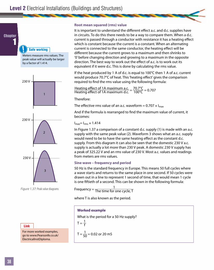
Level 2 Electrical Installations (Buildings and Structures)
38
Chapter
1
Worked example
What is the period for a 50 Hz supply?
T = 1f
T = 150 = 0.02 or 20 mS
Root mean squared (rms) valueIt is important to understand the di erent e ect a.c. and d.c. supplies have in circuits. To do this there needs to be a way to compare them. When a d.c. current is passed through a conductor with resistance it has a heating e ect which is constant because the current is a constant. When an alternating current is connected to the same conductor, the heating e ect will be di erent because the current grows to a maximum and then shrinks to ‘0’ before changing direction and growing to a maximum in the opposite direction. The best way to work out the e ect of a.c. is to work out its equivalent if it were d.c. This is done by calculating the rms value.
If the heat produced by 1 A of d.c. is equal to 100°C then 1 A of a.c. current would produce 70.7°C of heat. This ‘heating e ect’ gives the comparison required to nd the rms value using the following formula:
Heating effect of 1A maximum a.c.Heating e ect of 1A maximum d.c. = 70.7°C
100°C = 0.707
Therefore:
The e ective rms value of an a.c. waveform = 0.707 × Imax
And if the formula is rearranged to nd the maximum value of current, it becomes:
Imax= Irms × 1.414
In Figure 1.37 a comparison of a constant d.c. supply (1) is made with an a.c. supply with the same peak value (2). Waveform 3 shows what an a.c. supply would need to be to have the same heating e ect as the constant d.c. supply. From this diagram it can also be seen that the domestic 230 V a.c. supply is actually a lot more than 230 V peak. A domestic 230 V supply has a peak of 325.22 V and an rms value of 230 V. Most a.c. values and readings from meters are rms values.
Sine wave – frequency and period50 Hz is the standard frequency in Europe. This means 50 full cycles where a wave starts and returns to the same place in one second. If 50 cycles were drawn out in a line to represent 1 second of time, that would mean 1 cycle is one ftieth of a second. This can be shown in the following formula:
Frequency = 1The time for one cycle, T
where T is also known as the period.
Link
For more worked examples, go to www.Pearsonfe.co.uk/ElectricalInstDiploma.
Safe working
Meters measure rms values. The peak value will actually be larger by a factor of 1.414.
!
Figure 1.37: Peak value diagrams
230 V
1 2 3
230 V
1 2 3
230 V
1 2 3
230 V
1 2 3
230 V
1 2 3
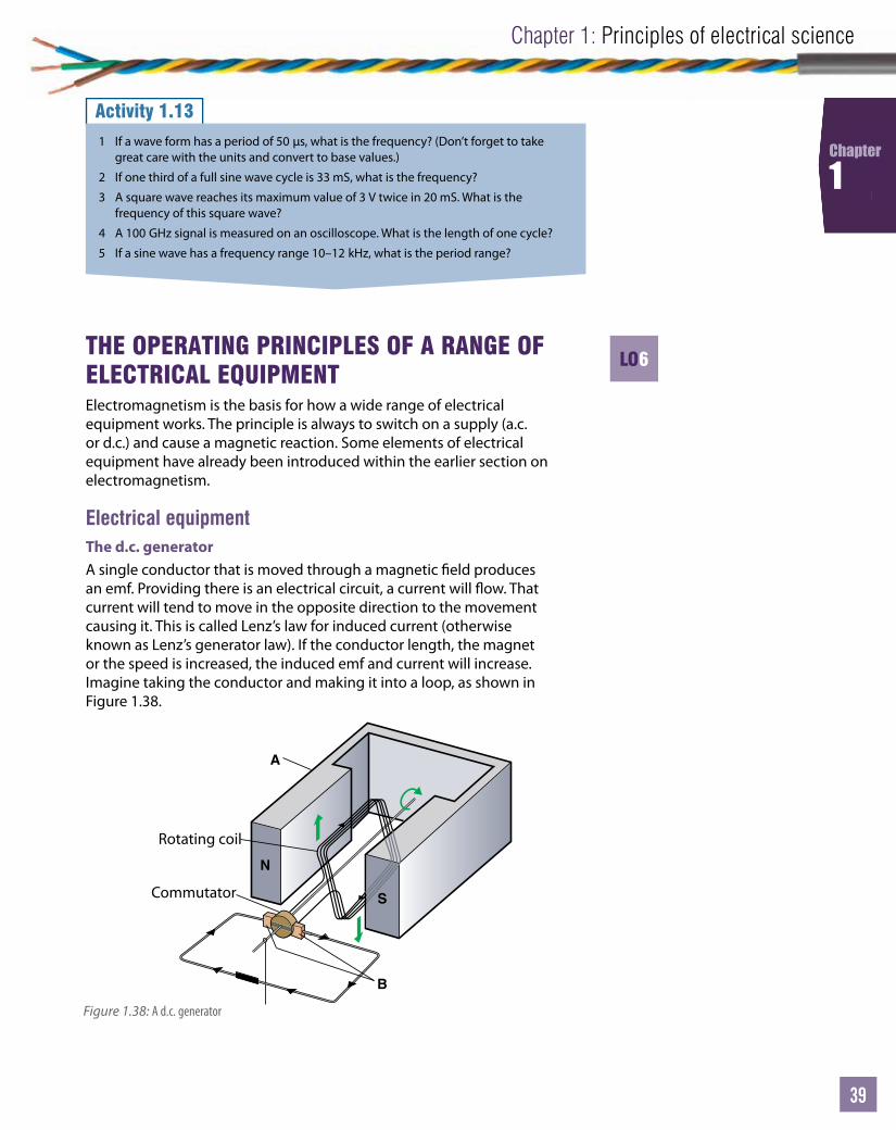
Unit
39
Chapter 1: Principles of electrical science
39
39
Chapter
1
THE OPERATING PRINCIPLES OF A RANGE OF ELECTRICAL EQUIPMENTElectromagnetism is the basis for how a wide range of electrical equipment works. The principle is always to switch on a supply (a.c. or d.c.) and cause a magnetic reaction. Some elements of electrical equipment have already been introduced within the earlier section on electromagnetism.
Electrical equipmentThe d.c. generatorA single conductor that is moved through a magnetic eld produces an emf. Providing there is an electrical circuit, a current will ow. That current will tend to move in the opposite direction to the movement causing it. This is called Lenz’s law for induced current (otherwise known as Lenz’s generator law). If the conductor length, the magnet or the speed is increased, the induced emf and current will increase. Imagine taking the conductor and making it into a loop, as shown in Figure 1.38.
Activity 1.131 If a wave form has a period of 50 µs, what is the frequency? (Don’t forget to take
great care with the units and convert to base values.)
2 If one third of a full sine wave cycle is 33 mS, what is the frequency?
3 A square wave reaches its maximum value of 3 V twice in 20 mS. What is the frequency of this square wave?
4 A 100 GHz signal is measured on an oscilloscope. What is the length of one cycle?
5 If a sine wave has a frequency range 10–12 kHz, what is the period range?
S
N
A
B
Rotating coil
Commutator
Figure 1.38: A d.c. generator
LO6

Level 2 Electrical Installations (Buildings and Structures)
40
Chapter
1
The circuit is now complete and the loop is rotating within the magnetic eld. The commutator allows the current to pass around the circuit in the same direction, as can be seen in Figure 1.41. As the loop rotates, the brushes keep contact with the moving commutator until the brushes reach the insulated divider. At this point the loop is about to start on the second half of its journey and the direction of the current changes. The commutator/brush arrangement allows the current to keep owing in the same direction as the loop passes the vertical position.
To make a larger emf and current, more loops of wire are required. For each extra loop, a further connection is required and this is achieved by adding more segments to the commutator. In reality, lots of loops and segments will make a much smoother d.c. current. An armature is made up of lots of loops formed around a core for strength.
The brushes are made of carbon for several reasons. Carbon, as it heats up with friction, has a negative temperature coe cient. This means that unlike most metals, as it gets hotter its resistance gets less, making it a better conductor. Carbon also self-lubricates to minimise friction. Springs behind the carbon push the brushes on to the commutator segments to keep a constant pressure and good contact. Timely maintenance is important to make sure the carbon brushes are replaced when they have worn down.
Rotation
N S
The coil can be moved around an axis by rotating it. As the conductor cuts the magnetic eld lines, an emf and current will be induced into the coil. If you look at Figures 1.39 and 1.40, you will notice one side of the loop is moving upwards and the other side is moving downwards to give the rotation.
As the loop reaches the horizontal position it cuts the highest density of ux lines that exist directly between the magnet poles. However, as the loop reaches the vertical position, it is moving parallel to the magnetic ux lines – not cutting any at all! From this you can see that most emf is generated when the coil is horizontal and little or no emf is generated when the coil is vertical. To connect the turning loop up to a circuit, a commutator is used. For a single loop generator, a two copper segment commutator is required. The commutator is split and separated by an insulated material.
Figure 1.39: Wire loop within a permanent magnetic eld
A B C D A +
–
0° 180° 360°0
N N S S N N S S N S
A(0°)
Position
B(90°)
Position
C(180°)
Position
D(270°)
Position
A(360°)
Position
Note the rotation of the commutator during the cycle
Copper segment
Figure 1.40: Voltage output for one complete revolution
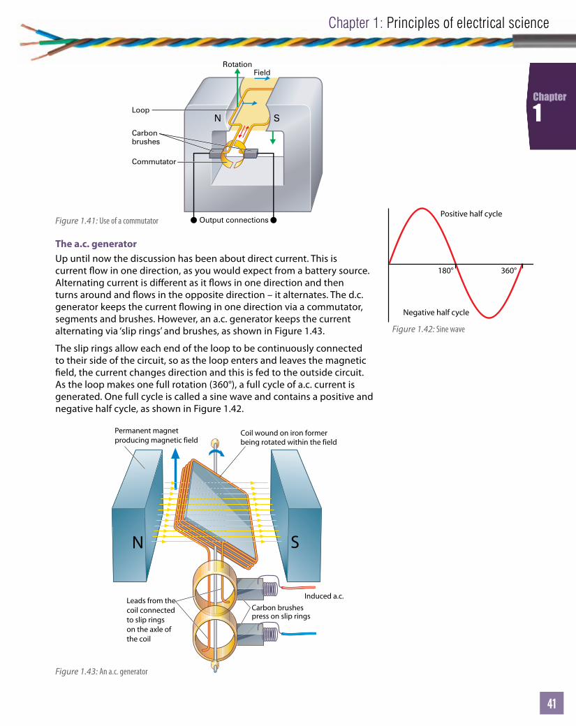
Unit
41
Chapter 1: Principles of electrical science
41
41
Chapter
1
The a.c. generatorUp until now the discussion has been about direct current. This is current ow in one direction, as you would expect from a battery source. Alternating current is di erent as it ows in one direction and then turns around and ows in the opposite direction – it alternates. The d.c. generator keeps the current owing in one direction via a commutator, segments and brushes. However, an a.c. generator keeps the current alternating via ‘slip rings’ and brushes, as shown in Figure 1.43.
The slip rings allow each end of the loop to be continuously connected to their side of the circuit, so as the loop enters and leaves the magnetic eld, the current changes direction and this is fed to the outside circuit. As the loop makes one full rotation (360°), a full cycle of a.c. current is generated. One full cycle is called a sine wave and contains a positive and negative half cycle, as shown in Figure 1.42.
Rotation
Loop
Commutator
Carbonbrushes
Output connections
Field
N S
Figure 1.41: Use of a commutatorPositive half cycle
Negative half cycle
180° 360°
Figure 1.42: Sine wave
Coil wound on iron formerbeing rotated within the field
Carbon brushes press on slip rings
Permanent magnetproducing magnetic field
Leads from thecoil connectedto slip ringson the axle ofthe coil
Induced a.c.
Figure 1.43: An a.c. generator

Level 2 Electrical Installations (Buildings and Structures)
42
Chapter
1
In the UK an a.c. generator will produce a sine wave that alternates 50 times a second. This is measured in hertz (Hz) and therefore the UK national supply is 50 Hz.
Fleming’s left-hand ‘motor’ ruleThe interaction that occurs is down to attracting and repulsion forces of magnetic ux lines.
N S
Figure 1.44: Current-carrying conductor between two magnetic poles
N S
Figure 1.45: Field caused by two magnetic poles
N S
Figure 1.46: Current-carrying conductor in a magnetic eld
First finger pointing in the direction of the Field (N to S)
SeCond finger pointing in the direction of the Current in the conductor
ThuMb points in the direction in which the conductor tends to Move
Figure 1.47: Fleming’s left-hand rule
As can be seen from these gures, the top of the conductor is experiencing a compression force as the ux lines are going in the same direction, hence repulsion. However, at the bottom of the conductor, the induced ux lines of the conductor and the permanent magnet are travelling in opposite directions. This causes attraction. At the top of the conductor there is a push and at the bottom a pulling force. This dual action will cause the conductor to be forced downwards – this is the d.c. motor principle.
A simple way to work out the direction of a current-carrying conductorin a magnetic eld is to use Fleming’s left-hand ‘motor’ rule, as seen in Figure 1.47.
Line up the rst nger with the permanent magnetic eld in the direction of North to South. The second nger is lined up with the direction of current ow. The direction of movement will now be shown by the direction of your thumb.
The operating principle of transformers Mutual inductance is the principle of how a transformer works. A changing magnetic ux caused by a changing current is required to set up a transformer e ect. This is why transformers are used with a.c. supplies and not d.c.
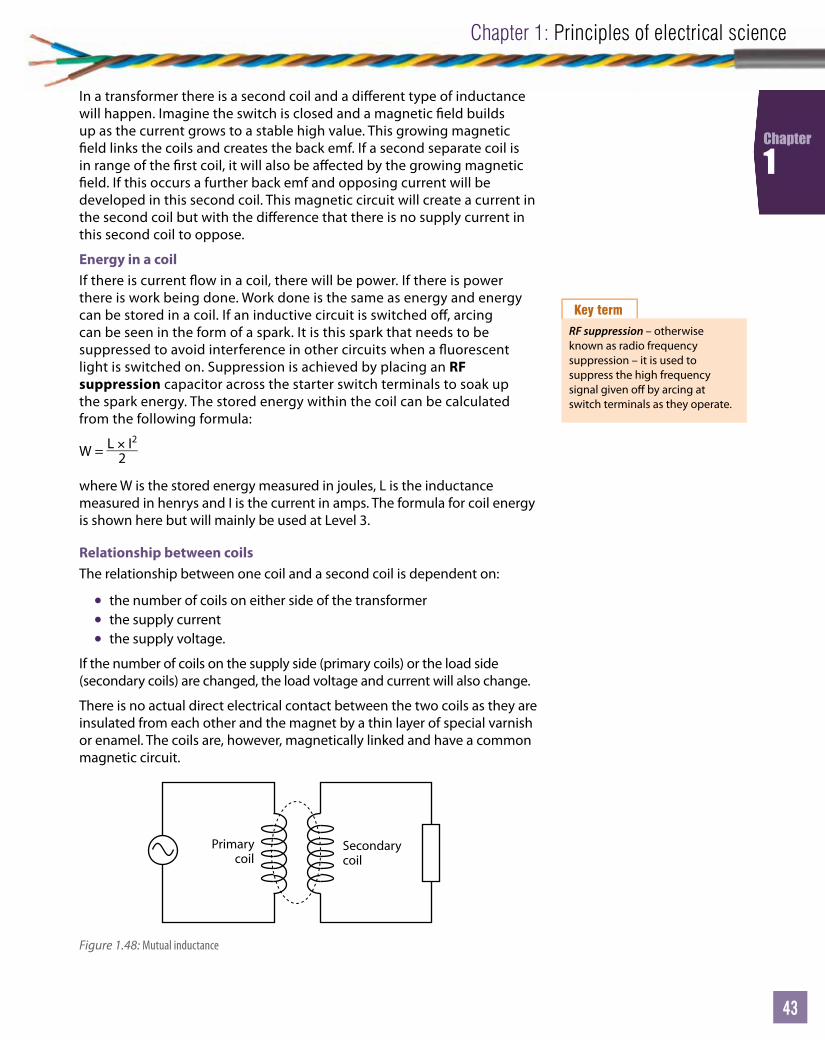
Unit
43
Chapter 1: Principles of electrical science
43
43
Chapter
1
In a transformer there is a second coil and a di erent type of inductance will happen. Imagine the switch is closed and a magnetic eld builds up as the current grows to a stable high value. This growing magnetic eld links the coils and creates the back emf. If a second separate coil is in range of the rst coil, it will also be a ected by the growing magnetic eld. If this occurs a further back emf and opposing current will be developed in this second coil. This magnetic circuit will create a current in the second coil but with the di erence that there is no supply current in this second coil to oppose.
Energy in a coilIf there is current ow in a coil, there will be power. If there is power there is work being done. Work done is the same as energy and energy can be stored in a coil. If an inductive circuit is switched o , arcing can be seen in the form of a spark. It is this spark that needs to be suppressed to avoid interference in other circuits when a uorescent light is switched on. Suppression is achieved by placing an RF suppression capacitor across the starter switch terminals to soak up the spark energy. The stored energy within the coil can be calculated from the following formula:
W = L × I2
2
where W is the stored energy measured in joules, L is the inductance measured in henrys and I is the current in amps. The formula for coil energy is shown here but will mainly be used at Level 3.
Relationship between coilsThe relationship between one coil and a second coil is dependent on:
• the number of coils on either side of the transformer• the supply current• the supply voltage.
If the number of coils on the supply side (primary coils) or the load side (secondary coils) are changed, the load voltage and current will also change.
There is no actual direct electrical contact between the two coils as they are insulated from each other and the magnet by a thin layer of special varnish or enamel. The coils are, however, magnetically linked and have a common magnetic circuit.
Key term
RF suppression – otherwise known as radio frequency suppression – it is used to suppress the high frequency signal given o by arcing at switch terminals as they operate.
Primary coil
Secondary coil
Figure 1.48: Mutual inductance
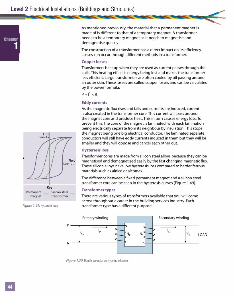
Level 2 Electrical Installations (Buildings and Structures)
44
Chapter
1
As mentioned previously, the material that a permanent magnet is made of is di erent to that of a temporary magnet. A transformer needs to be a temporary magnet as it needs to magnetise and demagnetise quickly.
The construction of a transformer has a direct impact on its e ciency. Losses can occur through di erent methods in a transformer.
Copper lossesTransformers heat up when they are used as current passes through the coils. This heating e ect is energy being lost and makes the transformer less e cient. Large transformers are often cooled by oil passing around an outer skin. These losses are called copper losses and can be calculated by the power formula:
P = I2 × R
Eddy currents As the magnetic ux rises and falls and currents are induced, current is also created in the transformer core. This current will pass around the magnet core and produce heat. This in turn causes energy loss. To prevent this, the core of the magnet is laminated, with each lamination being electrically separate from its neighbour by insulation. This stops the magnet being one big electrical conductor. The laminated separate conductors will still have eddy currents induced in them but they will be smaller and they will oppose and cancel each other out.
Hysteresis lossTransformer cores are made from silicon steel alloys because they can be magnetised and demagnetised easily by the fast changing magnetic ux. These silicon alloys have low hysteresis loss compared to harder ferrous materials such as alnico or alcomax.
The di erence between a xed permanent magnet and a silicon steel transformer core can be seen in the hysteresis curves (Figure 1.49).
Transformer typesThere are various types of transformers available that you will come across throughout a career in the building services industry. Each transformer type has a di erent purpose.
Fluxdensity
Permanentmagnet
KeySilicon steeltransformer
Fieldstrength
Figure 1.49: Hysteresis loop
IPVP NP NS VS
P
N
Primary winding Secondary winding
LOAD IS
Figure 1.50: Double wound, core-type transformer
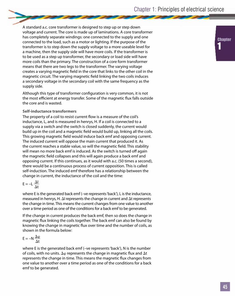
Unit
45
Chapter 1: Principles of electrical science
45
45
Chapter
1
A standard a.c. core transformer is designed to step up or step down voltage and current. The core is made up of laminations. A core transformer has completely separate windings: one connected to the supply and one connected to the load, such as a motor or lighting. If the purpose of the transformer is to step down the supply voltage to a more useable level for a machine, then the supply side will have more coils. If the transformer is to be used as a step up transformer, the secondary or load side will have more coils than the primary. The construction of a core form transformer means that there are two legs to the transformer. The varying voltage creates a varying magnetic eld in the core that links to the other coil in the magnetic circuit. The varying magnetic eld linking the two coils induces a secondary voltage in the secondary coil with the same frequency as the supply side.
Although this type of transformer con guration is very common, it is not the most e cient at energy transfer. Some of the magnetic ux falls outside the core and is wasted.
Self-inductance transformersThe property of a coil to resist current ow is a measure of the coil’s inductance, L, and is measured in henrys, H. If a coil is connected to a supply via a switch and the switch is closed suddenly, the current would build up in the coil and a magnetic eld would build up, linking all the coils. This growing magnetic eld would induce back emf and opposing current. The induced current will oppose the main current that produced it. As the current reaches a stable value, so will the magnetic eld. This stability will mean no more back emf is induced. As the switch is turned o again the magnetic eld collapses and this will again produce a back emf and opposing current. If this continues, as it would with a.c. (50 times a second), there would be a continuous process of current opposition. This is called self-induction. The induced emf therefore has a relationship between the change in current, the inductance of the coil and the time:
E = –L It
where E is the generated back emf (–ve represents ‘back’), L is the inductance, measured in henrys, H. I represents the change in current and t represents the change in time. This means the current changes from one value to another over a time period as one of the conditions for a back emf to be generated.
If the change in current produces the back emf, then so does the change in magnetic ux linking the coils together. The back emf can also be found by knowing the change in magnetic ux over time and the number of coils, as shown in the formula below:
E = –N t
where E is the generated back emf (–ve represents ‘back’), N is the number of coils, with no units. represents the change in magnetic ux and t represents the change in time. This means the magnetic ux changes from one value to another over a time period as one of the conditions for a back emf to be generated.
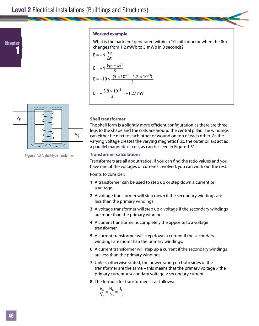
Level 2 Electrical Installations (Buildings and Structures)
46
Chapter
1
Shell transformerThe shell form is a slightly more e cient con guration as there are three legs to the shape and the coils are around the central pillar. The windings can either be next to each other or wound on top of each other. As the varying voltage creates the varying magnetic ux, the outer pillars act as a parallel magnetic circuit, as can be seen in Figure 1.51.
Transformer calculationsTransformers are all about ‘ratios’. If you can nd the ratio values and you have one of the voltages or currents involved, you can work out the rest.
Points to consider:
1 A transformer can be used to step up or step down a current or a voltage.
2 A voltage transformer will step down if the secondary windings are less than the primary windings.
3 A voltage transformer will step up a voltage if the secondary windings are more than the primary windings.
4 A current transformer is completely the opposite to a voltage transformer.
5 A current transformer will step down a current if the secondary windings are more than the primary windings.
6 A current transformer will step up a current if the secondary windings are less than the primary windings.
7 Unless otherwise stated, the power rating on both sides of the transformer are the same – this means that the primary voltage × the primary current = secondary voltage × secondary current.
8 The formula for transformers is as follows:
Vp
Vs =
Np
Ns =
Is
Ip
Worked example
What is the back emf generated within a 10 coil inductor when the ux changes from 1.2 mWb to 5 mWb in 3 seconds?
E = –N t
E = –N (2 – 1)
3
E = –10 × (5 × 10–3 – 1.2 × 10⁻³)3
E = – 3.8 × 10⁻³
3 = –1.27 mV
VP
VS
Figure 1.51: Shell-type transformer
Unit
47
Chapter 1: Principles of electrical science
47
47
Chapter
1
Worked example
A transformer has a primary voltage of 230 V and primary windings with 100 turns. The secondary windings are 50 turns. What is the secondary voltage?
Step 1What is this: a voltage or current transformer?It is a voltage transformer.
Step 2Is it a step up or step down voltage transformer? It is a step down transformer as there are fewer turns on the secondary windings.
Step 3What is the ratio?The ratio is 100 : 50.
To simplify a ratio, simply divide both sides by the smallest number, in this case 50, to give:10050
: 5050
= 2 : 1
This is a 2 : 1 step down voltage transformer.
Step 4Apply the ratio to the voltage to nd what the secondary voltage should be.230
2 = 115 V
Link
For more worked examples, go to www.pearsonfe.co.uk/ElectricalInstDiploma.
It is a good idea to draw a diagram and label it to determine what information you have and what you need to nd. The temptation with transformer questions is to do them in your head. This will come with time but the key is lots of practice – don’t take chances with something that is this simple but also equally simple to slip up on.
Activity 1.141 A transformer has a primary voltage of 230 V and a secondary of 12 V. If the primary
turns are 200, how many turns are there on the secondary side?
2 A core transformer has 3 A at the output and is supplied by 12 A, 400 V. What is the secondary voltage?
3 A shell transformer has a turns ratio of 20 : 1 and a secondary voltage of 23 V. What is the primary voltage?
4 A transformer is supplied with 200 V at 3 A. If the secondary current is 15 A, what is the secondary voltage?
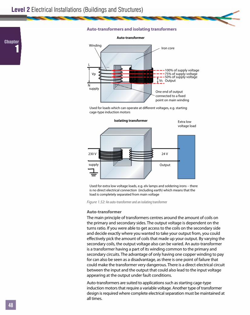
Level 2 Electrical Installations (Buildings and Structures)
48
Chapter
1
Auto-transformers and isolating transformers
100% of supply voltage75% of supply voltage50% of supply voltage
Vs
Vp
supply
supply
230 V 24 V
Winding
Auto-transformer
Isolating transformer Extra low voltage load
Used for loads which can operate at dierent voltages, e.g. startingcage-type induction motors
Used for extra low voltage loads, e.g. elv lamps and soldering irons – thereis no direct electrical connection (including earth) which means that theload is completely separated from main voltage
One end of outputconnected to a xedpoint on main winding
Iron core
L
NOutput
Output
Figure 1.52: An auto-transformer and an isolating transformer
Auto-transformerThe main principle of transformers centres around the amount of coils on the primary and secondary sides. The output voltage is dependent on the turns ratio. If you were able to get access to the coils on the secondary side and decide exactly where you wanted to take your output from, you could e ectively pick the amount of coils that made up your output. By varying the secondary coils, the output voltage also can be varied. An auto-transformer is a transformer having a part of its winding common to the primary and secondary circuits. The advantage of only having one copper winding to pay for can also be seen as a disadvantage, as there is one point of failure that could make the transformer very dangerous. There is a direct electrical circuit between the input and the output that could also lead to the input voltage appearing at the output under fault conditions.
Auto-transformers are suited to applications such as starting cage-type induction motors that require a variable voltage. Another type of transformer design is required where complete electrical separation must be maintained at all times.
Unit
49
Chapter 1: Principles of electrical science
49
49
Chapter
1
Isolating transformerWhere water is concerned, electrical separation is particularly important. Transformers are still required to bring voltages down to extra low voltage levels but the possibility of completing an electric circuit and getting a shock must be minimised. Applications such as shaving sockets are supplied via isolating transformers that do not share a common earth. The two sides of the transformer are electrically separated from earth and from other systems. This means that a fault cannot give rise to the risk of electric shock.
THE PRINCIPLES OF BASIC MECHANICSAs an electrician, other scienti c principles need to be understood if you are to make use of electricity e ciently. Basic mechanics will help determine the work, e ort and power required to move an object.
Calculating quantities of mechanical loadsMass and weightMass and weight are two terms that often get confused and misused. Mass is the amount of substance or ‘stu ’ that exists in an object. This amount of substance does not change unless you do something to the object (for example, break a bit o ). The value of mass is therefore a constant and does not change wherever it is, even if it is on the Moon. The standard unit for mass is the kilogram or kg (1 kg = 1 000 gm).
Weight is one of the most misused terms in science. If someone asks you: ‘How much do you weigh?’, generally you will give an answer in stones or kilograms – this is not strictly correct! Weight is a combined e ect of mass and gravity. Gravity or gravitational pull is an e ect that the Earth has on all things that have a mass. The further away from sea level, the weaker the gravitation pull. Gravity is something you could observe if you dropped your drill from the top of a ladder and it accelerated to the ground. If you hold a drill you are holding the mass of the drill but also you are overcoming the gravitational acceleration that the Earth is exerting on it. What you can feel is the true weight of the drill, or the force. This force is measured in newtons, N, and is given by the formula:
Force = Mass × Acceleration
F = ma
Using acceleration due to gravity, ‘a’ can be replaced with the constant for gravity, ‘g’, giving:
F = mg
Progress check 1.2
1 How do you calculate the energy stored in a coil?
2 De ne inductance in a coil.
3 What is the transformer formula?
Key term
Gravity – acceleration due to gravity can be taken as a constant value of 9.81 ms–2. If you took your drill to the Moon it would weigh approximately one sixth in comparison to its weight on Earth.
Worked example
A photovoltaic solar panel has a mass of 48 kg. What weight force would you need to consider when installing it on a roof?
M = 48 kgG = 9.81 ms-2
F = mgF = 48 × 9.81 = 470.88 N
Link
For more worked examples, go to www.pearsonfe.co.uk/ElectricalInstDiploma.
LO4
Level 2 Electrical Installations (Buildings and Structures)
50
Chapter
1
Potential energy (PE)Energy comes in many forms. Energy does not get lost – it just converts to other forms. Energy put into a machine or process always equals energy that comes out of the machine or process. Some energy is not very useful, such as vibration, smoke, sparks or heat.
Work and energyEvery time an object is moved from one place to another, work has been done. The amount of work done depends on the force used and distance you have moved the object either up and down or side to side. For this instance we are just considering moving an object horizontally (vertically will come later).
Using common sense, the following statements must be true.
• More force used = more work done.• Greater the distance moved = more work done.
The relationship between work, force and distance can be shown in the formula:
Work done (energy used) = Force × Distance
Activity 1.151 What is the force due to gravity on a control panel with a mass of 15 kg?
2 What is the mass of a cable drum with a weight force of 108.2 N?
3 How many cable drums of mass 27 kg each can a trolley rated at 1 kN carry in one trip?
Key term
Work done – this is the same as energy used. Both are measured in joules, J, and 1 joule of energy is said to have been used if a force of 1 N moves an object 1 m.
Worked example
How much work has been done if a force of 12 N moves a control panel 15 m across a room?
F = 12 ND = 15 mW = FdW = 12 × 15 = 180 J
Link
For more worked examples, go to www.pearsonfe.co.uk/ElectricalInstDiploma.
Activity 1.161 What energy do you use when moving a street light from a highways depot store to
your van? It requires a force of 16 N and the distance is 25 m.
2 What energy is required when loading your van with three cable drums? Each drum takes 10 N of force and the distance is 10 m.
3 How far do you move if the total work done moving your site lockup box is 2500 J and the force used is 3 N?
4 What energy will be spent moving a 200 kg transformer core 12 m into position for installation?
5 What energy will be used moving 7 × 25 kg photovoltaic panels 20 m from the delivery pallet to winch position?

Unit
51
Chapter 1: Principles of electrical science
51
51
Chapter
1
Worked example
Consider this – you have to drill a hole 1 500 mm above xed oor level ( ). What potential energy (PE) will there be if the 3.5 kg SDS drill is to be lifted from your tool box on the oor to the marked spot on the wall?
PE = mghm = 3.5 kgg = 9.81 ms–2
h = 1 500 mm = 1.5 m (convert to base unit of length, m)PE = 3.5 × 9.81 × 1.5 = 51.5 J
Link
For more worked examples, go to www.pearsonfe.co.uk/ElectricalInstDiploma.
Key term
Fixed oor level ( ) – the nished oor level that is the starting point for measurements. This term is often abbreviated to .
Up until now you have just considered moving an object across a oor – now imagine moving an object up a oor, vertically. Every object has potential energy or stored energy. An example might be a drill that is about to be picked up. This drill has potential energy – it also has a known mass (for example, a standard 36 V SDS cordless drill has a mass of around 3.5 kg). To be picked up, you will also have to overcome the gravitational pull of the Earth. The amount of potential energy is also related to how high the drill will be raised.
This can be shown by the formula:
PE = m × g × h
Energy and powerIf energy is expelled and work is done when moving an object a certain distance, what happens if the object is moved even quicker? Imagine you are moving two large boxes 20 m. You take your time to move the rst box – you are not out of breath and you are not sweating. However, by the time you get to the second box, you are in a hurry and you move it in half the time. You are out of breath and you are now sweating. That is because you have used much more power! So the general rule is the shorter the time you take to move an object, the greater the power you use. Power is related to the work done in the amount of time it took and is measured in watts, W.
Activity 1.171 Calculate the potential energy of a cable drum that has a mass of 50 kg and which is
to be lifted 0.75 m into the back of a truck.
2 Calculate the height a cable tray has been lifted if the potential energy is 1 kJ and the mass is 20 kg.
3 Calculate the mass of a tool chest that has a potential energy of 250 J and requires lifting 1.75 m back on to the store shelf.
4 Calculate the potential energy of a pallet of solar panels with a mass of 100 kg to be lifted on to a roof at a height of 6 m.
5 A control panel for a motor is to be lifted up a 30 m riser. The control panel is labelled up as 2000 N. What is the potential energy of the control panel?

Level 2 Electrical Installations (Buildings and Structures)
52
Chapter
1Worked example
A 25 kg drum of mineral-insulated cable has to be pushed into the storage lockup 30 m away. You have 2 minutes to complete the move as your supervisor wants to leave site – how much power will you use? (Keep this simple and ignore considerations such as slopes and friction – in reality these would need to be considered but not at this level.)
Step 1 – write down what you know/have been given:m = 25 kgd = 30 mt = 2 mins = 120 s (convert to base unit of time, s)F = mgW = Fd
P = Wt
Step 2 – what can you work out from the facts you have? F = mgF = 25 × 9.81 = 245.25 Nand:W = FdW = 245.25 × 30 = 7357.5 J (or 7.3575 kJ)so:P = W
t
P = 7357.5120
= 61.31 W
Link
For another worked example, go to www.pearsonfe.co.uk/ElectricalInstDiploma.
Activity 1.181 How much power will you use if you move a 50 kg crate of stripped copper 50 m to
the recycling bin in 5 minutes?
2 You use 500 kJ of energy moving a uorescent bulb crushing machine from the tailgate of a delivery truck to your electrical storage area which is 75 m away and it takes you half an hour. How much does it weigh?
3 How much power will you use if you move a conduit bending machine (mass of 20 kg) a distance of 30 m in 30 seconds?
4 How much power will you use moving a pallet of contactors with a mass of 78 kg from your van to the installation position 12.5 m away in 2 minutes?
5 You need to move a ground source heat pump 35 m from your secure lockup to the installation point. The pump weighs 75 kg and you have 20 minutes to do the task. How much power will you exert doing the move?
Power can be expressed as a relationship between work done and the time taken, using the formula:
Power, P = Work done (W)Time taken to do the work (t)
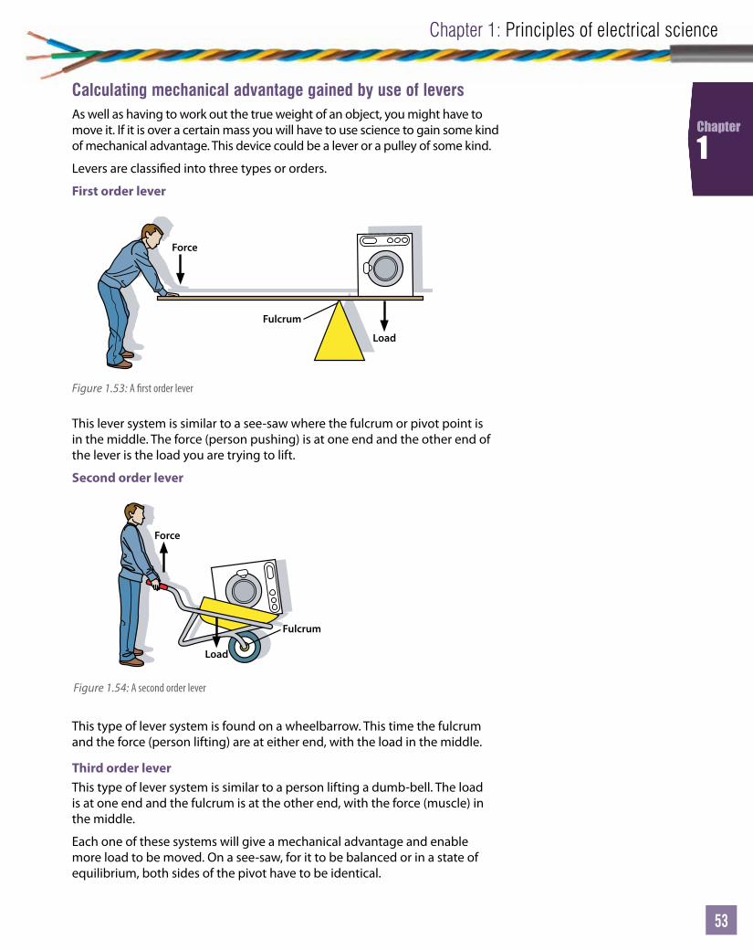
Unit
53
Chapter 1: Principles of electrical science
53
53
Chapter
1
Calculating mechanical advantage gained by use of leversAs well as having to work out the true weight of an object, you might have to move it. If it is over a certain mass you will have to use science to gain some kind of mechanical advantage. This device could be a lever or a pulley of some kind.
Levers are classi ed into three types or orders.
First order lever
Load
Force
Fulcrum
Figure 1.53: A rst order lever
This lever system is similar to a see-saw where the fulcrum or pivot point is in the middle. The force (person pushing) is at one end and the other end of the lever is the load you are trying to lift.
Second order lever
Force
Load
Fulcrum
Figure 1.54: A second order lever
This type of lever system is found on a wheelbarrow. This time the fulcrum and the force (person lifting) are at either end, with the load in the middle.
Third order leverThis type of lever system is similar to a person lifting a dumb-bell. The load is at one end and the fulcrum is at the other end, with the force (muscle) in the middle.
Each one of these systems will give a mechanical advantage and enable more load to be moved. On a see-saw, for it to be balanced or in a state of equilibrium, both sides of the pivot have to be identical.

Level 2 Electrical Installations (Buildings and Structures)
54
Chapter
1 Force
Load
Fulcrum
There is a rule that states the e ort × the length to the fulcrum must equal the load × the length to the fulcrum for it to be balanced. This means that if you are trying to lift something really heavy, it can be done if you move the fulcrum closer to the load. This can be calculated using the formula:
F1D1 = F2D2
where F1 is the e ort, F2 is the load force you are trying to lift, and D1 and D2 are the distances to the fulcrum from the person and the load respectively.
Figure 1.55: A third order lever
Link
For more worked examples, go to www.pearsonfe.co.uk/ElectricalInstDiploma.
Activity 1.191 A rst order lever is used to raise a motor o the ground. The lever is 2.75 m long and
you are 1.9 m from the fulcrum. The motor is 200 kg. What force will you exert?
2 The same scenario as Question 1, but this time the motor has increased to 300 kg. How much force will be required now?
Worked example
F2 = F1 × D1D2
F2 = 32.86 N (or 3.35 kg if you divide by gravity, 9.81)
F1110 N
D1230 mm
D2770 mm
F2?
Pulley systemsLevers are a good way of gaining mechanical advantage. Another way is to use a pulley system. There are several types of pulley system available.

Unit
55
Chapter 1: Principles of electrical science
55
55
Chapter
1
Fixed single pulley systemIn the single pulley system shown in Figure 1.55, a force of 2 kg × g (9.81) is required to overcome gravity. If the mass had to be moved 3 m, the person pulling the rope would need to pull in 3 m of rope. There is no real advantage apart from potentially convenience.
Moveable pulley systemWith a moveable pulley system, as shown in Figure 1.56, the mass of 2 kg is shared between the two ropes suspending it. This means that the e ort required to lift it is 1 kg × g = 9.81 N. In this system a mechanical advantage has been gained. This mechanical advantage (MA) can be calculated using the formula:
MA = LoadE ort
MA = 2 kg × 9.811 kg × 9.81
= 2
Multiple pulley systemsWhere more pulleys and ropes are used, greater mechanical advantage can be gained. To calculate your e ort, simply divide the load by the number of ropes that the mass is suspended by. In Figure 1.57, the mass is suspended by four ropes that share the 200 kg equally. Each rope is therefore subjected to 50 kg. Using this information, the applied force must be 50 kg × 9.81 = 490.5 N, which gives you an MA of 4.
EfficiencyE ciency is de ned as the ratio of useable output energy (or power) to the energy (or power) you have to put in. The symbol for e ciency is η (Greek, eta). Simply, no machine is perfect and no matter how much energy you put into it, not all of it will be converted to something useful like movement. Some energy or power will be lost in the form of heat, vibration or generation of noise or smoke.
E ciency is extremely important to an electrician, as you will need to know how much electricity or e ort to put into a machine to get the output you want. If there are too many losses or there is too much wasted energy, there may not be enough left to turn a motor or power a load. It is worth noting that it is impossible for a system to be 100 per cent e cient.
E ciency is a ratio and has no units but is commonly shown as a percentage. E ciency can be expressed with the formula:
E ciency, η = Useful output power (or energy)Input power (or energy)
× 100%
Worked example
If the input power to a motor is 1100 W and the output power is 800 W, what is the e ciency of the motor?
e ciency, η = 8001100
× 100% = 72.72%
Link
For more worked examples, go to www.pearsonfe.co.uk/ElectricalInstDiploma.
1 kg 1 kg1 kg × g
Applied force
2 kg2 kg
5050
5050
50
Applied force50 × 9.81 = 490.5 N
200 kg200 kg
3 m
Applied force
2 kg2 kg
Figure 1.55: A xed single pulley system
Figure 1.56: A moveable pulley system
Figure 1.57: A multiple pulley system

Level 2 Electrical Installations (Buildings and Structures)
56
Chapter
1
THE PRINCIPLES OF A.C. THEORYYou have looked at the d.c. world, including Ohm’s law and how current and voltage are related to resistance. In a d.c. circuit the analogy to water is very strong. If there is resistance then a larger pressure (voltage/potential di erence) is required to force the current through the obstruction (resistance). This holds true for the a.c. single-phase circuits as well. Three-phase a.c. circuits are the next logical step, which is why they are covered last (and slightly out of order with the running order of outcomes in the speci cation).
The effects of components in a.c. circuitsAn extra level of complexity comes into play with an a.c. circuit due to the way some components react to a varying supply. The reactions to an a.c. supply must be understood by an electrician when designing, testing or fault nding a circuit. An a.c. circuit is exactly that, an alternating circuit. This means that unlike a d.c. circuit, where current is pushed around a circuit in one direction, in an a.c. circuit the current changes direction 50 times a second (that is what 50 Hz means). In an a.c. circuit, the current starts at a value of ‘0’ and builds up to a maximum before returning to ‘0’ and repeating the process in a negative direction.
You have already seen that an a.c. supply acts in a slightly di erent way in comparison to a d.c. supply when connected to a load. In a d.c. circuit a capacitor acts as a total block to current due to the layer of insulation in the dielectric – all that can happen is the capacitor plates charge up to the same value as the supply battery. A coil of wire acts as a long piece of wire and hence has resistance when connected into a d.c. supply. In an a.c. circuit things are a little di erent.
If an a.c. circuit was perfect and just had resistance in it, the voltage and current sine waves would be completely in phase, that is they would reach maximum peak values at exactly the same time as shown in Figure 1.58 and also represented by the phasor diagram in Figure 1.59.
This is not that easy to achieve if there is anything that looks like a coil or capacitor in the a.c. circuit. Remember, two cables lying next to each other can be considered a capacitor.
Activity 1.201 A machine has losses of 3.1 kW and it requires 56 kW to run. What is the required
input power?
2 What is the e ciency of the above machine?
3 If the same machine is serviced and the overall e ciency improves by 1%, what is the new input power required?
4 A motor is 97.3% e cient and produces 16.7 kW of output power. What input power is required to achieve this?
5 A d.c. motor has a loss of 3.1 kW due to vibration and friction. If the input power is 22 kW, what is the e ciency of the motor?
Key term
Phasor – a phasor diagram is a slightly di erent representation of the sine wave. Imagine the phasor is rotating about a xed point as per the generator coil spinning in a magnetic eld. The direction of rotation is anticlockwise.
LO7
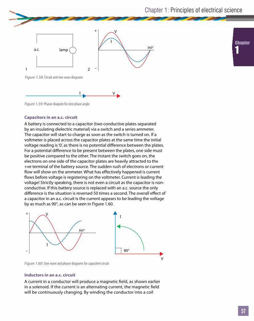
Unit
57
Chapter 1: Principles of electrical science
57
57
Chapter
1
Inductors in an a.c. circuitA current in a conductor will produce a magnetic eld, as shown earlier in a solenoid. If the current is an alternating current, the magnetic eld will be continuously changing. By winding the conductor into a coil
Capacitors in an a.c. circuitA battery is connected to a capacitor (two conductive plates separated by an insulating dielectric material) via a switch and a series ammeter. The capacitor will start to charge as soon as the switch is turned on. If a voltmeter is placed across the capacitor plates at the same time the initial voltage reading is ‘0’, as there is no potential di erence between the plates. For a potential di erence to be present between the plates, one side must be positive compared to the other. The instant the switch goes on, the electrons on one side of the capacitor plates are heavily attracted to the +ve terminal of the battery source. The sudden rush of electrons or current ow will show on the ammeter. What has e ectively happened is current ows before voltage is registering on the voltmeter. Current is leading the voltage! Strictly speaking, there is not even a circuit as the capacitor is non-conductive. If this battery source is replaced with an a.c. source the only di erence is the situation is reversed 50 times a second. The overall e ect of a capacitor in an a.c. circuit is the current appears to be leading the voltage by as much as 90°, as can be seen in Figure 1.60.
V +
–
360°
I
a.c. lamp
1 2
V I
Figure 1.58: Circuit and sine wave diagrams
Figure 1.59: Phasor diagram for zero phase angle
V
I
V +
–
360°
I
90°
Figure 1.60: Sine wave and phasor diagrams for capacitive circuitV
I
V +
–
360°
I
90°
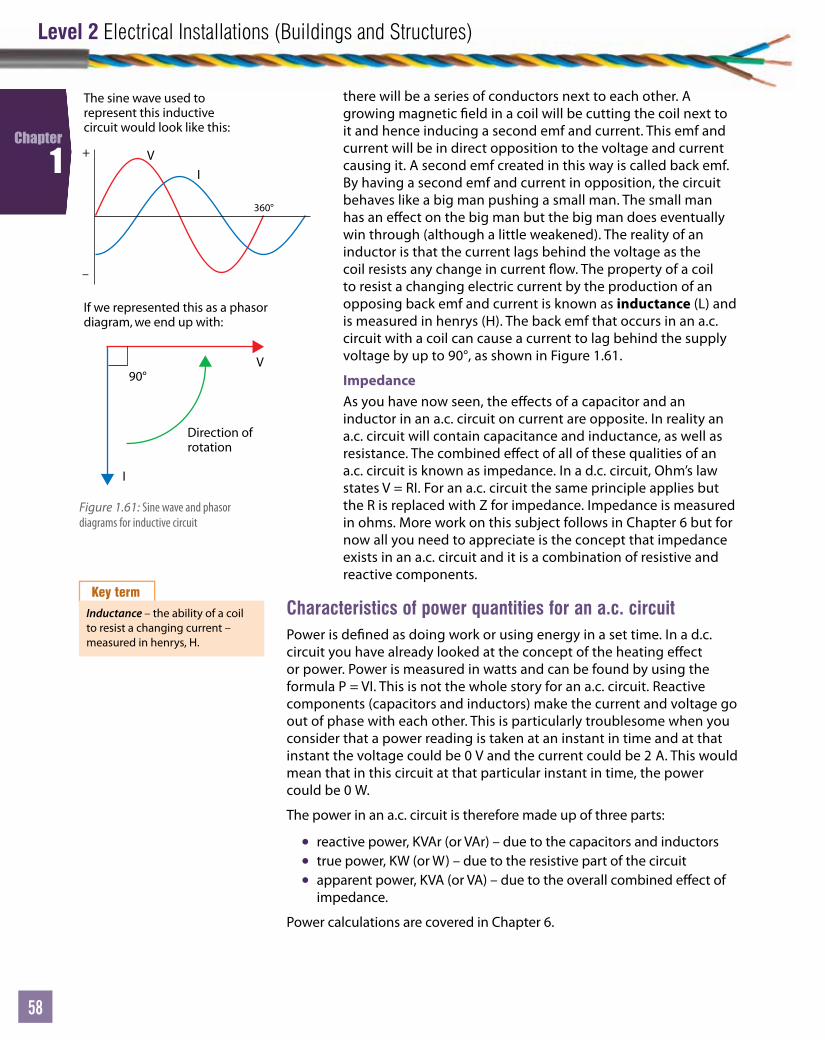
Level 2 Electrical Installations (Buildings and Structures)
58
Chapter
1
there will be a series of conductors next to each other. A growing magnetic eld in a coil will be cutting the coil next to it and hence inducing a second emf and current. This emf and current will be in direct opposition to the voltage and current causing it. A second emf created in this way is called back emf. By having a second emf and current in opposition, the circuit behaves like a big man pushing a small man. The small man has an e ect on the big man but the big man does eventually win through (although a little weakened). The reality of an inductor is that the current lags behind the voltage as the coil resists any change in current ow. The property of a coil to resist a changing electric current by the production of an opposing back emf and current is known as inductance (L) and is measured in henrys (H). The back emf that occurs in an a.c. circuit with a coil can cause a current to lag behind the supply voltage by up to 90°, as shown in Figure 1.61.
ImpedanceAs you have now seen, the e ects of a capacitor and an inductor in an a.c. circuit on current are opposite. In reality an a.c. circuit will contain capacitance and inductance, as well as resistance. The combined e ect of all of these qualities of an a.c. circuit is known as impedance. In a d.c. circuit, Ohm’s law states V = RI. For an a.c. circuit the same principle applies but the R is replaced with Z for impedance. Impedance is measured in ohms. More work on this subject follows in Chapter 6 but for now all you need to appreciate is the concept that impedance exists in an a.c. circuit and it is a combination of resistive and reactive components.
V
I
V +
–
360°
I
The sine wave used to represent this inductive circuit would look like this:
If we represented this as a phasordiagram, we end up with:
Direction of rotation
90°
Figure 1.61: Sine wave and phasor diagrams for inductive circuit
Key term
Inductance – the ability of a coil to resist a changing current – measured in henrys, H.
Characteristics of power quantities for an a.c. circuitPower is de ned as doing work or using energy in a set time. In a d.c. circuit you have already looked at the concept of the heating e ect or power. Power is measured in watts and can be found by using the formula P = VI. This is not the whole story for an a.c. circuit. Reactive components (capacitors and inductors) make the current and voltage go out of phase with each other. This is particularly troublesome when you consider that a power reading is taken at an instant in time and at that instant the voltage could be 0 V and the current could be 2 A. This would mean that in this circuit at that particular instant in time, the power could be 0 W.
The power in an a.c. circuit is therefore made up of three parts:
• reactive power, KVAr (or VAr) – due to the capacitors and inductors• true power, KW (or W) – due to the resistive part of the circuit• apparent power, KVA (or VA) – due to the overall combined e ect of
impedance.
Power calculations are covered in Chapter 6.
Unit
59
Chapter 1: Principles of electrical science
59
59
Chapter
1
Why power factor correction is required and how it may be achievedAn e cient a.c. circuit needs to draw the least amount of current possible for the job it is trying to do. The most e cient a.c. circuit only contains resistance. You have seen that a capacitor has the opposite e ect to an inductor on voltage and current. If a circuit contains resistance and inductors, the overall e ect on that circuit will be inductive. If a capacitor is added to this circuit, some of the inductive e ect can be balanced out. If it is very carefully calculated, a capacitor can be put into an a.c. circuit and make it seem as though it just contains resistance. If this were the case the voltage and current would be completely in phase with each other. The angle between the voltage and current in an a.c. circuit is known as the power factor angle. Power factor correction is achieved by placing a capacitor in parallel with an inductive load. The capacitor used in this kind of supply correction is known as a power factor correction capacitor.
Industrial sites may contain very large equipment that runs on a.c. supplies. Large industrial sites mean a large number of inductors in the form of machine windings, transformer coils and uorescent light chokes or ballasts. All of these ‘inductors’ will cause the site to have a large phase shift between the current and voltage (remember, a coil will cause current to lag behind voltage by up to 90°).
Power factor correction can be achieved by a number of di erent methods, including:
• capacitors• load correction• bulk correction• synchronous motor.
A typical example of pf or power factor correction would be a large site with banks of uorescent lights (discharge lighting). Each light contains an inductive coil or choke.
If the current and voltage sine waves were displayed using an oscilloscope, you would notice the voltage and current are out of phase. This leads to an overall e ect of more current being drawn from the supply than is required to power the lights. A power factor correction capacitor is therefore required in each uorescent tube to counter the e ect of the coil. For industrial sites it may be practical to monitor this as a whole installation and then correct the site rather than the individual equipment. This is known as load correction or bulk correction and can be automated with correction added as the power factor angle drifts in to unacceptable levels.
On a much larger scale, this type of correction is carried out on the electricity supplier’s network and again is automated.
Key terms
Power factor correction – also referred to as pf correction, it is the ability to bring the current in phase with the voltage.
Synchronous motor – power factor correction is used on large induction motors because it has a leading power factor.
Fluorescent – a uorescent tube inductive coil is also referred to as a choke or ballast.
Progress check 1.3
1 De ne what e ect a capacitor and inductor will have on an a.c. circuit.
2 What is impedance?
3 What is power factor and why does it need correction?
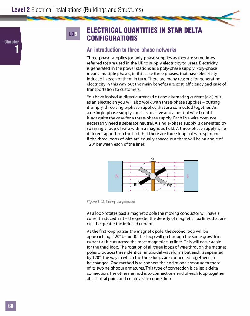
Level 2 Electrical Installations (Buildings and Structures)
60
Chapter
1
ELECTRICAL QU ANTITIES IN STAR DELTA CONFIGURATIONS
An introduction to three-phase networksThree-phase supplies (or poly-phase supplies as they are sometimes referred to) are used in the UK to supply electricity to users. Electricity is generated in the power stations as a poly-phase supply. Poly-phase means multiple phases, in this case three phases, that have electricity induced in each of them in turn. There are many reasons for generating electricity in this way but the main bene ts are cost, e ciency and ease of transportation to customers.
You have looked at direct current (d.c.) and alternating current (a.c.) but as an electrician you will also work with three-phase supplies – putting it simply, three single-phase supplies that are connected together. An a.c. single-phase supply consists of a live and a neutral wire but this is not quite the case for a three-phase supply. Each live wire does not necessarily need a separate neutral. A single-phase supply is generated by spinning a loop of wire within a magnetic eld. A three-phase supply is no di erent apart from the fact that there are three loops of wire spinning. If the three loops of wire are equally spaced out there will be an angle of 120° between each of the lines.
N S
Br
GyBl
Figure 1.62: Three-phase generation
As a loop rotates past a magnetic pole the moving conductor will have a current induced in it – the greater the density of magnetic ux lines that are cut, the greater the induced current.
As the rst loop passes the magnetic pole, the second loop will be approaching (120° behind). This loop will go through the same growth in current as it cuts across the most magnetic ux lines. This will occur again for the third loop. The rotation of all three loops of wire through the magnet poles produces three identical sinusoidal waveforms but each is separated by 120°. The way in which the three loops are connected together can be changed. One method is to connect the end of one armature to those of its two neighbour armatures. This type of connection is called a delta connection. The other method is to connect one end of each loop together at a central point and create a star connection.
LO5

Unit
61
Chapter 1: Principles of electrical science
61
61
Chapter
1
Delta connection
VPVL
IP
IBr
IBl
IGy
Figure 1.63: Delta connection
VL
IP
IBr
IN
IBl
IGy
VP
Figure 1.64: Star connection
A star con gured supply is the typical supply that can be found in your street. It consists of three separate line conductors, each with a separate supply on it. A star system also has a neutral and an earth conductor. You can see from Figure 1.64 that the centre point of the star is connected down to earth and also onwards connected to give an extra conductor – this is the neutral.
This type of connection has three lines only. Each end of the transformer phase is connected to another to form a triangle con guration. To get a supply voltage you connect between any two of the lines. There is only one level of voltage that can be found. You can see from Figure 1.63 that no earth or neutral are available on a delta con gured system.
The current owing through the transformer winding is called the phase current and the current owing through the line is called the line current. As the current ows through the line and gets to the junction with the other two phases, it has two other possible routes to ow down. This means the current must split. On a delta system there are two di erent values of current owing. The two di erent currents can be found by the formula IL = √3 × IP. On a delta system there is only one voltage so VL = VP.
Star connection

Level 2 Electrical Installations (Buildings and Structures)
62
Chapter
1
Transformers reducethe voltage to 33000 Vor 11 000 V for factories.
Transformers increase thevoltage to 400 000 volts . Thishelps to stop energy being wastedas heat in the transmission lines.
Transformers in locasub-stations reducethe voltage to 400/230Vfor homes, shopsand offices.
Power station
230 V 11kV
33kV11kV
400kV
l
Figure 1.65: The national grid
A star connection has an advantage over the delta because not only can you go across two lines to get a particular voltage, you can also connect between any line and a neutral. Connecting between a line and a neutral will give a di erent voltage. This means two di erent voltage levels are available on the star connected supply. If you connect between two lines you will get a line voltage. If you connect between a line and a neutral (e ectively across a single-phase) you will get the phase voltage. In a domestic street supply the line voltage would be 400 V and the phase voltage would be 230 V. These voltages can be found by the formula VL = √3 × VP .
The current owing through the phase winding on a star system is also called the phase current and the current owing through the line is called the line current. As the current ows along the line and reaches the junction with the phase winding, there is only one route so the line current and the phase current must be the same thing – it simply travels along the line, turns the corner and becomes the phase current. For this reason, IL = IP.
Unit
63
Chapter 1: Principles of electrical science
63
63
Chapter
1
The advantage of a star connected network is not only the di erent levels of voltage supply available but fewer neutrals are required. E ectively the three lines share the same neutral.
Three-phase supplies are the preferred way of local distribution to domestic streets and houses. If all the loads, i.e. the demands from houses split over a three-phase supply, are equal then the currents drawn on each of the lines are equal. If the currents are identical but 120° apart, the sum of these at any point in time is ‘zero’.
This means that if the currents stay balanced (i.e. equal) the current that ows down the neutral is also ‘zero’ and the neutral can also be made smaller. Reducing the size of the conductor saves money for the supply company. However, if the currents become unbalanced, the out-of-balance current will ow down the neutral. If this out-of-balance current gets too big, the neutral can heat up (one of the e ects of current ow in a conductor).
Safe working
If the lines are not balanced in a star supply, the neutral can heat up and fail. This is a common problem on developments where planning has not taken into account growth in demand for electricity.
!
Case study
A college experienced such a rapid growth in learners that extra temporary buildings were built to house them. The extra electricity required for heating, computers and workshop machinery led to the supply becoming unbalanced. The neutral heated up because one line in particular was supplying most of the extra current. When it snowed and even more electricity was required, the path of the underground supply cable melted the snow with the excessive heat produced. Eventually the supply transformer fuse blew, putting the whole college into darkness for a few hours! The supply was redesigned, balanced and a new supply was installed.
Key facts
1 For a star connected network, a balanced load is preferred as no current ows down the neutral and means the neutral can be small.
2 A star connected supply (three line and neutral) has an advantage over delta because of the neutral and the two di erent available voltages.
3 Delta has one voltage and two currents, star has one current and two voltages.
Progress check 1.4
1 What happens if a three-phase supply is not balanced?
2 Draw and label a star network.
3 Draw and label a delta network.

Level 2 Electrical Installations (Buildings and Structures)
64
Chapter
1
Knowledge check
Attempt all 15 multiple choice questions, which are based on the basic science covered in this chapter. If you are not successful in getting all of the answers correct, go back over the chapter and attempt them again.
1 What is the unit for magnetic ux density?
a Wbb Tc Hzd Ω
2 34 000 000 J can also be written as what?
a 34 MJb 340 kJc 3.4 MJd 34,000 MJ
3 72 × (3 × 3 + 3) can be simpli ed to what?
a 444b 120c 588d 882
4 If copper has a resistivity of 17.5 × 10⁻⁹, what is the resistance of a 25 m length of 2.5 mm2 conductor?
a 1.75 Ωb 0.175 Ωc 17.5 Ωd 175 Ω
5 What is the resistance of a series circuit with resistors of 3 Ω, 6 Ω, 9 Ω?
a 1.64 Ωb 162 Ωc 27 Ωd 18 Ω
6 A parallel circuit consists of two resistors: R1 = 2.5 Ω, R2 = 1.2 Ω. If the circuit is connected to a 12 V supply, what is the total circuit current?
a 10 Ab 1.5 Ac 15 mAd 15 A
7 A parallel circuit has four resistors of 1.7 MΩ, 2.3 MΩ, 2.9 MΩ, 5.7 MΩ. This parallel circuit is now connected to a 400 V supply. What is the total circuit current drawn by the loads?
a 617.3 Ab 6.3 Ac 16 Ad 0.617 mA
8 What is the magnetic ux density of a magnet with a cross-sectional area of 0.3 m2 and a ux of 4 Wb?
a 13.33 Tb 1.2 Tc 4.3 Td 43 mWb/m2
9 A 280 kg mass is suspended by four ropes on a moveable pulley system. What is the mechanical advantage?
a 5b 2c 4d 1
10 What force will a 0.6 m conductor experience if it has a 3 mA current owing through it when placed in a 5 T magnetic eld?
a 90 Tb 9.0 Tc 0.009 Td 900 T
11 A sine wave reaches the same peak value twice in 50 mS. What is the frequency of the sine wave?
a 50 Hzb 500 Hzc 200 Hzd 20 Hz
12 What energy has been used moving a 200 kg transformer core 12 m into position for installation?
a 23.544 kJb 2.44 kJc 16.67 kJd 16.67 J
13 A motor is 97.3% e cient and produces 16.7 kW of power at its output. What input power is required to achieve this?
a 16.25 kWb 19.4 kWc 17.16 kWd 1.6 MW
14 What is the best power factor?
a Unityb 0.99c 0.1d 0
15 A transformer has a turns ratio of 3 : 1 and a secondary current of 3 A. What is its primary current?
a 9 Ab 3 Ac 0.1 Ad 1 A