2-CHANNEL HIGH DEFINITION AUDIO CODEC WITH STAC9202 · data sheet 2-channel high definition audio...
135
DATA SHEET 2-CHANNEL HIGH DEFINITION AUDIO CODEC WITH STAC9202 IDT™ 2-CHANNEL HIGH DEFINITION AUDIO CODEC WITH DUAL DIGITAL MICROPHONE INTERFACES 1 STAC9202 V 1.2 01/08 IDT CONFIDENTIAL DESCRIPTION The STAC9202 is a high fidelity, 2-channel audio CODEC compli- ant with the High Definition Audio (HD Audio) specification defined by Intel. The STAC9202 implements direct interface to two digital microphones supporting advanced beam forming applications resulting in increased quality of applications requiring voice input. FEATURES • High-integration HD Audio Product • 2-channel PC Audio CODEC • Dual Digital Microphone interface • Two-Channel DACs and ADCs with 24-bit sample resolution • High performance ΣΔ technology • Sample rates up to 192 Hz • 100dB DAC SNR • Integrated Headphone Amps • Stereo Analog Microphone • Supports Stereo Microphone • Microphone Boost 0, 10, 20, 30, 40dB • Dual Digital Microphone Interface optimized for use with Akustica Digital Microphones • S/PDIF In and Out • Universal Jacks ™ Functionality for jack retasking • Adjustable VREF Out • Digital PC Beep to all outputs • +3.3 V, +4 V and +5 V analog power supply options • 48-pin LQFP Environmental Package DESCRIPTION The STAC9202 is a high fidelity, 2-channel, audio CODEC compliant with the High Definition Audio (HD Audio) specifi- cation defined by Intel. The STAC9202 provides high qual- ity, HD Audio capability to notebook and cost sensitive desktop PC applications. The STAC9202 incorporates IDT's proprietary ΣΔ technol- ogy to achieve a DAC SNR of 100 dB. The higher perfor- mance and quality of IDT’s audio solutions brings consumer electronics level performance to the notebook, desktop and media center PC. The STAC9202 provides stereo, 24-bit, full duplex resolu- tion supporting sample rates up to 192 KHz by the DAC and ADC. The STAC9202 SPDIF In/Out support sample rates of 96 KHz, 48 KHz and 44.1 KHz plus SPDIF_OUT supports 88.2 KHz. Additional sample rates are supported by the driver software. The STAC9202 supports flexible configurations including switchable Headphone Out and Universal Jacks™ func- tionality for jack detection and re-tasking. The SPDIF inter- face provides connectivity to Consumer Electronic equipment like Dolby Digital decoders, powered speakers, mini disk drives or to a home entertainment system. All analog I/O pairs support LINE_IN, LINE_OUT and MIC.
Transcript of 2-CHANNEL HIGH DEFINITION AUDIO CODEC WITH STAC9202 · data sheet 2-channel high definition audio...

DATA SHEET
2-CHANNEL HIGH DEFINITION AUDIO CODEC WITH STAC9202
IDT™ 2-CHANNEL HIGH DEFINITION AUDIO CODEC WITH DUAL DIGITAL MICROPHONE INTERFACES 1 STAC9202 V 1.2 01/08
IDT CONFIDENTIAL
DESCRIPTIONThe STAC9202 is a high fidelity, 2-channel audio CODEC compli-ant with the High Definition Audio (HD Audio) specification defined by Intel. The STAC9202 implements direct interface to two digital microphones supporting advanced beam forming applications resulting in increased quality of applications requiring voice input.
FEATURES• High-integration HD Audio Product• 2-channel PC Audio CODEC• Dual Digital Microphone interface
• Two-Channel DACs and ADCs with 24-bit sample resolution• High performance ΣΔ technology• Sample rates up to 192 Hz• 100dB DAC SNR
• Integrated Headphone Amps
• Stereo Analog Microphone• Supports Stereo Microphone• Microphone Boost 0, 10, 20, 30, 40dB
• Dual Digital Microphone Interface optimized for use with Akustica Digital Microphones
• S/PDIF In and Out
• Universal Jacks™ Functionality for jack retasking
• Adjustable VREF Out
• Digital PC Beep to all outputs
• +3.3 V, +4 V and +5 V analog power supply options
• 48-pin LQFP Environmental Package
DESCRIPTIONThe STAC9202 is a high fidelity, 2-channel, audio CODEC compliant with the High Definition Audio (HD Audio) specifi-cation defined by Intel. The STAC9202 provides high qual-ity, HD Audio capability to notebook and cost sensitive desktop PC applications.
The STAC9202 incorporates IDT's proprietary ΣΔ technol-ogy to achieve a DAC SNR of 100 dB. The higher perfor-mance and quality of IDT’s audio solutions brings consumer electronics level performance to the notebook, desktop and media center PC.
The STAC9202 provides stereo, 24-bit, full duplex resolu-tion supporting sample rates up to 192 KHz by the DAC and ADC. The STAC9202 SPDIF In/Out support sample rates of 96 KHz, 48 KHz and 44.1 KHz plus SPDIF_OUT supports 88.2 KHz. Additional sample rates are supported by the driver software.
The STAC9202 supports flexible configurations including switchable Headphone Out and Universal Jacks™ func-tionality for jack detection and re-tasking. The SPDIF inter-face provides connectivity to Consumer Electronic equipment like Dolby Digital decoders, powered speakers, mini disk drives or to a home entertainment system. All analog I/O pairs support LINE_IN, LINE_OUT and MIC.

STAC92022-CHANNEL HIGH DEFINITION AUDIO CODEC WITH DUAL DIGITAL MICROPHONE INTERFACES PC AUDIO
IDT™ 2-CHANNEL HIGH DEFINITION AUDIO CODEC WITH DUAL DIGITAL MICROPHONE INTERFACES 2 STAC9202 V 1.2 01/08
IDT CONFIDENTIAL
Table of Contents1. DESCRIPTION ...........................................................................................................................9
1.1. Overview ........................................................................................................................................... 91.2. Features .......................................................................................................................................... 10
2. CHARACTERISTICS ..............................................................................................................112.1. Audio Fidelity .................................................................................................................................. 112.2. Electrical Specifications ................................................................................................................... 112.3. STAC9202 5V Analog Performance Characteristics ....................................................................... 132.4. STAC9202 4V Analog Performance Characteristics ....................................................................... 142.5. STAC9202 3.3V Analog Performance Characteristics .................................................................... 142.6. Power Consumption ........................................................................................................................ 15
3. DETAILED DESCRIPTION ......................................................................................................163.1. SPDIF Input ..................................................................................................................................... 163.2. SPDIF Output .................................................................................................................................. 163.3. Digital Microphone Support ............................................................................................................. 163.4. Mono Out ......................................................................................................................................... 163.5. Headphone Drivers Restrictions ...................................................................................................... 163.6. Universal Jacks ............................................................................................................................... 17
4. FUNCTIONAL BLOCK DIAGRAM ..........................................................................................184.1. STAC9202 ....................................................................................................................................... 18
5. WIDGET DIAGRAM .................................................................................................................195.1. STAC9202 Widget Diagram ............................................................................................................ 195.2. STAC9202 Widget List ................................................................................................................... 205.3. Root Node (NID = 0x00) .................................................................................................................. 215.4. AFG Node (NID = 0x01) .................................................................................................................. 225.5. DAC0Cnvtr Node (NID = 0x02) ....................................................................................................... 375.6. ADC0Cnvtr Node (NID = 0x03) ....................................................................................................... 415.7. SPDIFinCnvtr Node (NID = 0x04) ................................................................................................... 465.8. SPDIFoutCnvtr Node (NID = 0x05) ................................................................................................. 525.9. DAC0Mux Node (NID = 0x06) ......................................................................................................... 575.10. DigInPin Node (NID = 0x07) .......................................................................................................... 605.11. DigOutPin Node (NID = 0x08) ....................................................................................................... 665.12. ADC0VolMux Node (NID = 0x09) .................................................................................................. 715.13. MasterVol Node (NID = 0x0E) ....................................................................................................... 755.14. InPortMux Node (NID = 0x0F) ....................................................................................................... 785.15. PortAPin Node (NID = 0x0A) ......................................................................................................... 825.16. PortDPin Node (NID = 0x0D) ........................................................................................................ 885.17. PortCPin Node (NID = 0x0C) ........................................................................................................ 935.18. PortBPin Node (NID = 0x0B) ......................................................................................................... 995.19. MonoOutPin Node (NID = 0x10) ................................................................................................. 1055.20. CDPin Node (NID = 0x11) ........................................................................................................... 1105.21. MonoOutMix Node (NID = 0x12) ................................................................................................. 1135.22. PCBeep Node (NID = 0x13) ........................................................................................................ 1155.23. ADC0InMux Node (NID = 0x14) .................................................................................................. 1185.24. DigMicPin Node (NID = 0x15) ..................................................................................................... 123
6. ORDERING INFORMATION ..................................................................................................1276.1. STAC9202 Options and Part Numbers ......................................................................................... 127
7. PIN INFORMATION ...............................................................................................................1287.1. STAC9202 Pin Diagram ................................................................................................................ 1287.2. Pin Table for STAC9202 ............................................................................................................... 128
8. PACKAGE DRAWINGS .........................................................................................................1318.1. 48-Pin LQFP .................................................................................................................................. 131
9. SOLDER REFLOW PROFILE ...............................................................................................1329.1. Standard Reflow Profile Data ........................................................................................................ 132

STAC92022-CHANNEL HIGH DEFINITION AUDIO CODEC WITH DUAL DIGITAL MICROPHONE INTERFACES PC AUDIO
IDT™ 2-CHANNEL HIGH DEFINITION AUDIO CODEC WITH DUAL DIGITAL MICROPHONE INTERFACES 3 STAC9202 V 1.2 01/08
IDT CONFIDENTIAL
9.2. Pb Free Process - Package Classification Reflow Temperatures ................................................. 13310. REVISION HISTORY ...........................................................................................................134
List of FiguresFigure 1. STAC9202 Functional Block Diagram ........................................................................................... 18Figure 2. STAC9202 Widget Diagram .......................................................................................................... 19Figure 3. STAC9202 Pin Diagram .............................................................................................................. 128Figure 4. 48-Pin LQFP Package Outline and Package Dimensions ........................................................... 131Figure 5. Solder Reflow Profile ................................................................................................................... 132
List of TablesTable 1. Digital Power Consumption ............................................................................................................. 15Table 2. 5 V Analog Power Consumption ...................................................................................................... 15Table 3. High Definition Audio Widget ........................................................................................................... 20Table 4. Root PnpID Command Verb Format ................................................................................................ 21Table 5. Root PnpID Command Response Format ....................................................................................... 21Table 6. Root RevID Command Verb Format ................................................................................................ 21Table 7. Root RevID Command Response Format ....................................................................................... 21Table 8. Root NodeInfo Command Verb Format ........................................................................................... 22Table 9. Root NodeInfo Command Response Format .................................................................................. 22Table 10. AFG Reset Command Verb Format .............................................................................................. 22Table 11. AFG Reset Command Response Format ...................................................................................... 23Table 12. AFG NodeInfo Command Verb Format ......................................................................................... 23Table 13. AFG NodeInfo Command Response Format ................................................................................. 23Table 14. AFG Type Command Verb Format ................................................................................................ 24Table 15. AFG Type Command Response Format ....................................................................................... 24Table 16. AFG GrpCap Command Verb Format ........................................................................................... 24Table 17. AFG GrpCap Command Response Format ................................................................................... 24Table 18. AFG FrmtCap Command Verb Format .......................................................................................... 25Table 19. AFG FrmtCap Command Response Format ................................................................................. 25Table 20. AFG StreamCap Command Verb Format ...................................................................................... 26Table 21. AFG StreamCap Command Response Format ............................................................................. 26Table 22. AFG PwrCap Command Verb Format ........................................................................................... 26Table 23. AFG PwrCap Command Response Format .................................................................................. 27Table 24. AFG GPIOCap Command Verb Format ........................................................................................ 27Table 25. AFG GPIOCap Command Response Format ................................................................................ 28Table 26. AFG OutAmpCap Command Verb Format .................................................................................... 28Table 27. AFG OutAmpCap Command Response Format ........................................................................... 28Table 28. AFG PwrState Command Verb Format ......................................................................................... 29Table 29. AFG PwrState Command Response Format ................................................................................. 29Table 30. AFG UnsolResp Command Verb Format ...................................................................................... 29Table 31. AFG UnsolResp Command Response Format .............................................................................. 30Table 32. AFG GPIO Command Verb Format ............................................................................................... 30Table 33. AFG GPIO Command Response Format ...................................................................................... 30Table 34. AFG GPIOEn Command Verb Format .......................................................................................... 31Table 35. AFG GPIOEn Command Response Format .................................................................................. 31Table 36. AFG GPIODir Command Verb Format .......................................................................................... 32Table 37. AFG GPIODir Command Response Format .................................................................................. 32Table 38. AFG GPIOWake Command Verb Format ...................................................................................... 33Table 39. AFG GPIOWake Command Response Format ............................................................................. 33

STAC92022-CHANNEL HIGH DEFINITION AUDIO CODEC WITH DUAL DIGITAL MICROPHONE INTERFACES PC AUDIO
IDT™ 2-CHANNEL HIGH DEFINITION AUDIO CODEC WITH DUAL DIGITAL MICROPHONE INTERFACES 4 STAC9202 V 1.2 01/08
IDT CONFIDENTIAL
Table 40. AFG GPIOUnsolEn Command Verb Format ................................................................................. 33Table 41. AFG GPIOUnsolEn Command Response Format ......................................................................... 34Table 42. AFG GPIOSticky Command Verb Format ..................................................................................... 34Table 43. AFG GPIOSticky Command Response Format ............................................................................. 35Table 44. AFG SysID Command Verb Format .............................................................................................. 35Table 45. AFG SysID Command Response Format ...................................................................................... 36Table 46. AFG DigMic Command Verb Format ............................................................................................. 36Table 47. AFG DigMic Command Response Format .................................................................................... 36Table 48. DAC0Cnvtr Frmt Command Verb Format ...................................................................................... 37Table 49. DAC0Cnvtr Frmt Command Response Format ............................................................................. 37Table 50. DAC0Cnvtr WCap Command Verb Format ................................................................................... 38Table 51. DAC0Cnvtr WCap Command Response Format .......................................................................... 38Table 52. DAC0Cnvtr PwrState Command Verb Format .............................................................................. 39Table 53. DAC0Cnvtr PwrState Command Response Format ...................................................................... 39Table 54. DAC0Cnvtr Stream Command Verb Format ................................................................................. 40Table 55. DAC0Cnvtr Stream Command Response Format ......................................................................... 40Table 56. ADC0Cnvtr Frmt Command Verb Format ...................................................................................... 41Table 57. ADC0Cnvtr Frmt Command Response Format ............................................................................. 41Table 58. ADC0Cnvtr WCap Command Verb Format ................................................................................... 42Table 59. ADC0Cnvtr WCap Command Response Format .......................................................................... 42Table 60. ADC0Cnvtr ConnLen Command Verb Format .............................................................................. 43Table 61. ADC0Cnvtr ConnLen Command Response Format ...................................................................... 43Table 62. ADC0Cnvtr ConnLst Command Verb Format ................................................................................ 44Table 63. ADC0Cnvtr ConnLst Command Response Format ....................................................................... 44Table 64. ADC0Cnvtr ProcState Command Verb Format ............................................................................. 44Table 65. ADC0Cnvtr ProcState Command Response Format ..................................................................... 44Table 66. ADC0Cnvtr PwrState Command Verb Format .............................................................................. 45Table 67. ADC0Cnvtr PwrState Command Response Format ...................................................................... 45Table 68. ADC0Cnvtr Stream Command Verb Format ................................................................................. 45Table 69. ADC0Cnvtr Stream Command Response Format ......................................................................... 45Table 70. SPDIFinCnvtr Frmt Command Verb Format .................................................................................. 46Table 71. SPDIFinCnvtr Frmt Command Response Format ......................................................................... 46Table 72. SPDIFinCnvtr WCap Command Verb Format ............................................................................... 47Table 73. SPDIFinCnvtr WCap Command Response Format ....................................................................... 47Table 74. SPDIFinCnvtr FrmtCap Command Verb Format ........................................................................... 48Table 75. SPDIFinCnvtr FrmtCap Command Response Format ................................................................... 48Table 76. SPDIFinCnvtr StreamCap Command Verb Format ....................................................................... 49Table 77. SPDIFinCnvtr StreamCap Command Response Format .............................................................. 50Table 78. SPDIFinCnvtr ConnLen Command Verb Format ........................................................................... 50Table 79. SPDIFinCnvtr ConnLen Command Response Format .................................................................. 50Table 80. SPDIFinCnvtr ConnLst Command Verb Format ............................................................................ 50Table 81. SPDIFinCnvtr ConnLst Command Response Format ................................................................... 51Table 82. SPDIFinCnvtr Stream Command Verb Format .............................................................................. 51Table 83. SPDIFinCnvtr Stream Command Response Format ..................................................................... 51Table 84. SPDIFinCnvtr DigCtl Command Verb Format ............................................................................... 51Table 85. SPDIFinCnvtr DigCtl Command Response Format ....................................................................... 52Table 86. SPDIFoutCnvtr Frmt Command Verb Format ................................................................................ 52Table 87. SPDIFoutCnvtr Frmt Command Response Format ....................................................................... 53Table 88. SPDIFoutCnvtr WCap Command Verb Format ............................................................................. 54Table 89. SPDIFoutCnvtr WCap Command Response Format .................................................................... 54Table 90. SPDIFoutCnvtr FrmtCap Command Verb Format ......................................................................... 55Table 91. SPDIFoutCnvtr FrmtCap Command Response Format ................................................................ 55Table 92. SPDIFoutCnvtr StreamCap Command Verb Format ..................................................................... 56Table 93. SPDIFoutCnvtr StreamCap Command Response Format ............................................................ 56Table 94. SPDIFoutCnvtr Stream Command Verb Format ........................................................................... 56

STAC92022-CHANNEL HIGH DEFINITION AUDIO CODEC WITH DUAL DIGITAL MICROPHONE INTERFACES PC AUDIO
IDT™ 2-CHANNEL HIGH DEFINITION AUDIO CODEC WITH DUAL DIGITAL MICROPHONE INTERFACES 5 STAC9202 V 1.2 01/08
IDT CONFIDENTIAL
Table 95. SPDIFoutCnvtr Stream Command Response Format ................................................................... 56Table 96. SPDIFoutCnvtr DigCtl Command Verb Format ............................................................................. 57Table 97. SPDIFoutCnvtr DigCtl Command Response Format ..................................................................... 57Table 98. DAC0Mux WCap Command Verb Format ..................................................................................... 57Table 99. DAC0Mux WCap Command Response Format ............................................................................ 58Table 100. DAC0Mux ConnLen Command Verb Format .............................................................................. 58Table 101. DAC0Mux ConnLen Command Response Format ...................................................................... 59Table 102. DAC0Mux ConnSel Command Verb Format ............................................................................... 59Table 103. DAC0Mux ConnSel Command Response Format ...................................................................... 59Table 104. DAC0Mux ConnLst Command Verb Format ............................................................................... 59Table 105. DAC0Mux ConnLst Command Response Format ....................................................................... 59Table 106. DAC0Mux LR Command Verb Format ........................................................................................ 60Table 107. DAC0Mux LR Command Response Format ................................................................................ 60Table 108. DigInPin WCap Command Verb Format ...................................................................................... 60Table 109. DigInPin WCap Command Response Format ............................................................................. 61Table 110. DigInPin Cap Command Verb Format ......................................................................................... 61Table 111. DigInPin Cap Command Response Format ................................................................................ 62Table 112. DigInPin PwrState Command Verb Format ................................................................................. 62Table 113. DigInPin PwrState Command Response Format ........................................................................ 62Table 114. DigInPin Ctl Command Verb Format ........................................................................................... 63Table 115. DigInPin Ctl Command Response Format ................................................................................... 63Table 116. DigInPin UnsolResp Command Verb Format .............................................................................. 63Table 117. DigInPin UnsolResp Command Response Format ..................................................................... 64Table 118. DigInPin Sense Command Verb Format ..................................................................................... 64Table 119. DigInPin Sense Command Response Format ............................................................................. 64Table 120. DigInPin EAPD Command Verb Format ...................................................................................... 65Table 121. DigInPin EAPD Command Response Format ............................................................................. 65Table 122. DigInPin Config Command Verb Format ..................................................................................... 65Table 123. DigInPin Config Command Response Format ............................................................................. 66Table 124. DigOutPin WCap Command Verb Format ................................................................................... 66Table 125. DigOutPin WCap Command Response Format .......................................................................... 66Table 126. DigOutPin Cap Command Verb Format ...................................................................................... 67Table 127. DigOutPin Cap Command Response Format .............................................................................. 67Table 128. DigOutPin ConnLen Command Verb Format .............................................................................. 68Table 129. DigOutPin ConnLen Command Response Format ...................................................................... 68Table 130. DigOutPin ConnSel Command Verb Format ............................................................................... 69Table 131. DigOutPin ConnSel Command Response Format ...................................................................... 69Table 132. DigOutPin ConnLst Command Verb Format ............................................................................... 69Table 133. DigOutPin ConnLst Command Response Format ....................................................................... 69Table 134. DigOutPin Ctl Command Verb Format ........................................................................................ 70Table 135. DigOutPin Ctl Command Response Format ................................................................................ 70Table 136. DigOutPin Config Command Verb Format .................................................................................. 70Table 137. DigOutPin Config Command Response Format .......................................................................... 70Table 138. ADC0VolMux VolRight Command Verb Format .......................................................................... 71Table 139. ADC0VolMux VolRight Command Response Format ................................................................. 71Table 140. ADC0VolMux VolLeft Command Verb Format ............................................................................ 72Table 141. ADC0VolMux VolLeft Command Response Format .................................................................... 72Table 142. ADC0VolMux WCap Command Verb Format .............................................................................. 72Table 143. ADC0VolMux WCap Command Response Format ..................................................................... 72Table 144. ADC0VolMux OutAmpCap Command Verb Format .................................................................... 73Table 145. ADC0VolMux OutAmpCap Command Response Format ........................................................... 73Table 146. ADC0VolMux ConnLen Command Verb Format ......................................................................... 74Table 147. ADC0VolMux ConnLen Command Response Format ................................................................ 74Table 148. ADC0VolMux ConnLst Command Verb Format .......................................................................... 74Table 149. ADC0VolMux ConnLst Command Response Format .................................................................. 74

STAC92022-CHANNEL HIGH DEFINITION AUDIO CODEC WITH DUAL DIGITAL MICROPHONE INTERFACES PC AUDIO
IDT™ 2-CHANNEL HIGH DEFINITION AUDIO CODEC WITH DUAL DIGITAL MICROPHONE INTERFACES 6 STAC9202 V 1.2 01/08
IDT CONFIDENTIAL
Table 150. MasterVol Right Command Verb Format ..................................................................................... 75Table 151. MasterVol Right Command Response Format ............................................................................ 75Table 152. MasterVol Left Command Verb Format ....................................................................................... 75Table 153. MasterVol Left Command Response Format .............................................................................. 75Table 154. MasterVol WCap Command Verb Format ................................................................................... 76Table 155. MasterVol WCap Command Response Format .......................................................................... 76Table 156. MasterVol ConnLen Command Verb Format .............................................................................. 77Table 157. MasterVol ConnLen Command Response Format ...................................................................... 77Table 158. MasterVol ConnLst Command Verb Format ................................................................................ 77Table 159. MasterVol ConnLst Command Response Format ....................................................................... 77Table 160. InPortMux VolRight Command Verb Format ............................................................................... 78Table 161. InPortMux VolRight Command Response Format ....................................................................... 78Table 162. InPortMux VolLeft Command Verb Format .................................................................................. 78Table 163. InPortMux VolLeft Command Response Format ......................................................................... 78Table 164. InPortMux WCap Command Verb Format ................................................................................... 78Table 165. InPortMux WCap Command Response Format .......................................................................... 79Table 166. InPortMux ConnLen Command Verb Format .............................................................................. 79Table 167. InPortMux ConnLen Command Response Format ...................................................................... 80Table 168. InPortMux AmpCap Command Verb Format ............................................................................... 80Table 169. InPortMux AmpCap Command Response Format ...................................................................... 80Table 170. InPortMux ConnSel Command Verb Format ............................................................................... 81Table 171. InPortMux ConnSel Command Response Format ...................................................................... 81Table 172. InPortMux ConnLst0 Command Verb Format ............................................................................. 81Table 173. InPortMux ConnLst0 Command Response Format ..................................................................... 81Table 174. InPortMux ConnLst4 Command Verb Format ............................................................................. 81Table 175. InPortMux ConnLst4 Command Response Format ..................................................................... 82Table 176. PortAPin WCap Command Verb Format ..................................................................................... 82Table 177. PortAPin WCap Command Response Format ............................................................................ 82Table 178. PortAPin Cap Command Verb Format ........................................................................................ 83Table 179. PortAPin Cap Command Response Format ................................................................................ 83Table 180. PortAPin ConnLen Command Verb Format ................................................................................ 84Table 181. PortAPin ConnLen Command Response Format ........................................................................ 84Table 182. PortAPin ConnLst Command Verb Format .................................................................................. 84Table 183. PortAPin ConnLst Command Response Format ......................................................................... 84Table 184. PortAPin Ctl Command Verb Format ........................................................................................... 85Table 185. PortAPin Ctl Command Response Format .................................................................................. 85Table 186. PortAPin UnsolResp Command Verb Format ............................................................................. 85Table 187. PortAPin UnsolResp Command Response Format ..................................................................... 85Table 188. PortAPin Sense Command Verb Format ..................................................................................... 86Table 189. PortAPin Sense Command Response Format ............................................................................ 86Table 190. PortAPin Config Command Verb Format ..................................................................................... 87Table 191. PortAPin Config Command Response Format ............................................................................ 87Table 192. PortDPin WCap Command Verb Format ..................................................................................... 88Table 193. PortDPin WCap Command Response Format ............................................................................ 88Table 194. PortDPin Cap Command Verb Format ........................................................................................ 89Table 195. PortDPin Cap Command Response Format ................................................................................ 89Table 196. PortDPin ConnLen Command Verb Format ................................................................................ 89Table 197. PortDPin ConnLen Command Response Format ........................................................................ 90Table 198. PortDPin ConnLst Command Verb Format ................................................................................. 90Table 199. PortDPin ConnLst Command Response Format ......................................................................... 90Table 200. PortDPin Ctl Command Verb Format .......................................................................................... 90Table 201. PortDPin Ctl Command Response Format .................................................................................. 91Table 202. PortDPin UnsolResp Command Verb Format ............................................................................. 91Table 203. PortDPin UnsolResp Command Response Format ..................................................................... 91Table 204. PortDPin Sense Command Verb Format ..................................................................................... 92

STAC92022-CHANNEL HIGH DEFINITION AUDIO CODEC WITH DUAL DIGITAL MICROPHONE INTERFACES PC AUDIO
IDT™ 2-CHANNEL HIGH DEFINITION AUDIO CODEC WITH DUAL DIGITAL MICROPHONE INTERFACES 7 STAC9202 V 1.2 01/08
IDT CONFIDENTIAL
Table 205. PortDPin Sense Command Response Format ............................................................................ 92Table 206. PortDPin Config Command Verb Format .................................................................................... 92Table 207. PortDPin Config Command Response Format ............................................................................ 93Table 208. PortCPin WCap Command Verb Format ..................................................................................... 93Table 209. PortCPin WCap Command Response Format ............................................................................ 93Table 210. PortCPin Cap Command Verb Format ........................................................................................ 94Table 211. PortCPin Cap Command Response Format ................................................................................ 94Table 212. PortCPin ConnLen Command Verb Format ................................................................................ 95Table 213. PortCPin ConnLen Command Response Format ........................................................................ 95Table 214. PortCPin ConnLst Command Verb Format ................................................................................. 96Table 215. PortCPin ConnLst Command Response Format ......................................................................... 96Table 216. PortCPin Ctl Command Verb Format .......................................................................................... 96Table 217. PortCPin Ctl Command Response Format .................................................................................. 96Table 218. PortCPin UnsolResp Command Verb Format ............................................................................. 97Table 219. PortCPin UnsolResp Command Response Format ..................................................................... 97Table 220. PortCPin Sense Command Verb Format ..................................................................................... 98Table 221. PortCPin Sense Command Response Format ............................................................................ 98Table 222. PortCPin Config Command Verb Format .................................................................................... 98Table 223. PortCPin Config Command Response Format ............................................................................ 99Table 224. PortBPin WCap Command Verb Format ..................................................................................... 99Table 225. PortBPin WCap Command Response Format ............................................................................ 99Table 226. PortBPin Cap Command Verb Format ...................................................................................... 100Table 227. PortBPin Cap Command Response Format .............................................................................. 100Table 228. PortBPin ConnLen Command Verb Format .............................................................................. 101Table 229. PortBPin ConnLen Command Response Format ...................................................................... 101Table 230. PortBPin ConnLst Command Verb Format ................................................................................ 102Table 231. PortBPin ConnLst Command Response Format ....................................................................... 102Table 232. PortBPin Ctl Command Verb Format ......................................................................................... 102Table 233. PortBPin Ctl Command Response Format ................................................................................ 102Table 234. PortBPin UnsolResp Command Verb Format ........................................................................... 103Table 235. PortBPin UnsolResp Command Response Format ................................................................... 103Table 236. PortBPin Sense Command Verb Format ................................................................................... 104Table 237. PortBPin Sense Command Response Format .......................................................................... 104Table 238. PortBPin Config Command Verb Format ................................................................................... 104Table 239. PortBPin Config Command Response Format .......................................................................... 105Table 240. MonoOutPin Vol Command Verb Format .................................................................................. 105Table 241. MonoOutPin Vol Command Response Format ......................................................................... 105Table 242. MonoOutPin WCap Command Verb Format ............................................................................. 106Table 243. MonoOutPin WCap Command Response Format ..................................................................... 106Table 244. MonoOutPin Cap Command Verb Format ................................................................................. 107Table 245. MonoOutPin Cap Command Response Format ........................................................................ 107Table 246. MonoOutPin ConnLen Command Verb Format ......................................................................... 108Table 247. MonoOutPin ConnLen Command Response Format ................................................................ 108Table 248. MonoOutPin ConnLst Command Verb Format .......................................................................... 108Table 249. MonoOutPin ConnLst Command Response Format ................................................................. 108Table 250. MonoOutPin Ctl Command Verb Format ................................................................................... 109Table 251. MonoOutPin Ctl Command Response Format .......................................................................... 109Table 252. MonoOutPin Config Command Verb Format ............................................................................. 109Table 253. MonoOutPin Config Command Response Format .................................................................... 109Table 254. CDPin WCap Command Verb Format ....................................................................................... 110Table 255. CDPin WCap Command Response Format .............................................................................. 110Table 256. CDPin Cap Command Verb Format .......................................................................................... 111Table 257. CDPin Cap Command Response Format .................................................................................. 111Table 258. CDPin Ctl Command Verb Format ............................................................................................ 112Table 259. CDPin Ctl Command Response Format .................................................................................... 112

STAC92022-CHANNEL HIGH DEFINITION AUDIO CODEC WITH DUAL DIGITAL MICROPHONE INTERFACES PC AUDIO
IDT™ 2-CHANNEL HIGH DEFINITION AUDIO CODEC WITH DUAL DIGITAL MICROPHONE INTERFACES 8 STAC9202 V 1.2 01/08
IDT CONFIDENTIAL
Table 260. CDPin Config Command Verb Format ...................................................................................... 112Table 261. CDPin Config Command Response Format .............................................................................. 113Table 262. MonoOutMix WCap Command Verb Format ............................................................................. 113Table 263. MonoOutMix WCap Command Response Format .................................................................... 114Table 264. MonoOutMix ConnLen Command Verb Format ........................................................................ 114Table 265. MonoOutMix ConnLen Command Response Format ................................................................ 115Table 266. MonoOutMix ConnLst Command Verb Format ......................................................................... 115Table 267. MonoOutMix ConnLst Command Response Format ................................................................. 115Table 268. PCBeep Vol Command Verb Format ......................................................................................... 115Table 269. PCBeep Vol Command Response Format ................................................................................ 116Table 270. PCBeep WCap Command Verb Format .................................................................................... 116Table 271. PCBeep WCap Command Response Format ........................................................................... 116Table 272. PCBeep OutAmpCap Command Verb Format .......................................................................... 117Table 273. PCBeep OutAmpCap Command Response Format ................................................................. 117Table 274. PCBeep Gen Command Verb Format ....................................................................................... 117Table 275. PCBeep Gen Command Response Format .............................................................................. 118Table 276. ADC0InMux WCap Command Verb Format .............................................................................. 118Table 277. ADC0InMux WCap Command Response Format ..................................................................... 118Table 278. ADC0InMux ConnLen Command Verb Format ......................................................................... 119Table 279. ADC0InMux ConnLen Command Response Format ................................................................. 119Table 280. ADC0InMux ConnSel Command Verb Format .......................................................................... 120Table 281. ADC0InMux ConnSel Command Response Format ................................................................. 120Table 282. ADC0InMux ConnLst Command Verb Format .......................................................................... 120Table 283. ADC0InMux ConnLst Command Response Format .................................................................. 120Table 284. ADC0InMux LR Command Verb Format ................................................................................... 121Table 285. ADC0InMux LR Command Response Format ........................................................................... 121Table 286. ADC0InMux OutAmpCap Command Verb Format .................................................................... 121Table 287. ADC0InMux OutAmpCap Command Response Format ........................................................... 121Table 288. ADC0InMux VolRight Command Verb Format .......................................................................... 122Table 289. ADC0InMux VolRight Command Response Format .................................................................. 122Table 290. ADC0InMux VolLeft Command Verb Format ............................................................................. 122Table 291. ADC0InMux VolLeft Command Response Format .................................................................... 122Table 292. DigMicPin WCap Command Verb Format ................................................................................. 123Table 293. DigMicPin WCap Command Response Format ........................................................................ 123Table 294. DigMicPin Cap Command Verb Format .................................................................................... 124Table 295. DigMicPin Cap Command Response Format ............................................................................ 124Table 296. DigMicPin Ctl Command Verb Format ....................................................................................... 125Table 297. DigMicPin Ctl Command Response Format .............................................................................. 125Table 298. DigMicPin Config Command Verb Format ................................................................................. 125Table 299. DigMicPin Config Command Response Format ........................................................................ 125

STAC92022-CHANNEL HIGH DEFINITION AUDIO CODEC WITH DUAL DIGITAL MICROPHONE INTERFACES PC AUDIO
IDT™ 2-CHANNEL HIGH DEFINITION AUDIO CODEC WITH DUAL DIGITAL MICROPHONE INTERFACES 9 STAC9202 V 1.2 01/08
IDT CONFIDENTIAL
1. DESCRIPTION
1.1. Overview
The STAC9202 is a high fidelity, 2-channel, audio CODEC compliant with the High Definition Audio(HD Audio) specification defined by Intel. The STAC9202 provides high quality, HD Audio capabilityto notebook and cost sensitive desktop PC applications.
The STAC9202 incorporates IDT's proprietary ΣΔ technology to achieve a DAC SNR of 100 dB. Thehigher performance and quality of IDT’s audio solutions brings consumer electronics level perfor-mance to the notebook, desktop and media center PC.
The STAC9202 provides stereo, 24-bit, full duplex resolution supporting sample rates up to 192 KHzby the DAC and ADC. The STAC9202 SPDIF_IN/SPDIF_OUT support sample rates of 96 KHz,48 KHz and 44.1 KHz plus SPDIF_OUT supports 88.2 KHz. Additional sample rates are supportedby the driver software.
The STAC9202 supports flexible configurations including switchable Headphone Out and UniversalJacks™ functionality for jack detection and re-tasking. The SPDIF interface provides connectivity toConsumer Electronic equipment like Dolby Digital decoders, powered speakers, mini disk drives orto a home entertainment system. All analog I/O pairs support LINE_IN, LINE_OUT and MIC.
MIC inputs can be programmed with 0/10/20/30/40dB boost. For more advanced configurations, theSTAC9202 has four General Purpose I/O (GPIO) pins. The STAC9202 also provides a single endedCD input for compatibility with DRM solutions and to support legacy OS issues.
The STAC9202 integrates a headphone amplifier which is available on Ports A and D. The head-phone amplifier is switchable between these two outputs for increased flexibility, enhanced userexperience, and reduced implementation costs.
The Universal Jack capabilities allow the CODECs to detect when audio devices are connected tothe CODEC, and allow the CODECs to be reconfigured to support these devices, regardless ofwhich port they are plugged into. SPDIF input sensing is also supported. The fully parametric IDTSoftEQ can be initiated upon headphone jack insertion and removal for protection of notebookspeakers.
Note: The Jack Detect circuit and component selection are critical for accurate detection of audio jacks on individual ports. Please see the IDT STAC9202 reference design for circuit implementation details.
The STAC9202 operates with a 3.3 V digital supply and a 3.3 V, 4 V and 5 V analog supply.
The STAC9202 is available in a 48-pin LQFP Environmental (ROHS) package.
The STAC9202 implements a direct interface to two digital microphones, supporting advanced beamforming applications resulting in increased quality of applications requiring voice input.

STAC92022-CHANNEL HIGH DEFINITION AUDIO CODEC WITH DUAL DIGITAL MICROPHONE INTERFACES PC AUDIO
IDT™ 2-CHANNEL HIGH DEFINITION AUDIO CODEC WITH DUAL DIGITAL MICROPHONE INTERFACES 10 STAC9202 V 1.2 01/08
IDT CONFIDENTIAL
1.2. Features• High-integration HD Audio Product
• Two-channel PC Audio CODEC • Dual Digital Microphone interface
• Two-Channel DACs and ADCs with 24-bit sample resolution• High performance ΣΔ technology• Sample rates up to 192 KHz• 100dB DAC SNR
• Integrated Headphone Amps• Stereo Analog Microphone
• Supports Stereo Mic• Microphone Boost 0, 10, 20, 30, 40dB
• Dual Digital Microphone Interface optimized for use with Akustica Digital Microphones• S/PDIF In and Out • Universal Jacks™ Functionality for jack retasking• Adjustable VREF Out• Digital PC Beep to all outputs• +3.3 V, 4 V and +5 V analog power supply options• 48-pin LQFP Environmental Package

STAC92022-CHANNEL HIGH DEFINITION AUDIO CODEC WITH DUAL DIGITAL MICROPHONE INTERFACES PC AUDIO
IDT™ 2-CHANNEL HIGH DEFINITION AUDIO CODEC WITH DUAL DIGITAL MICROPHONE INTERFACES 11 STAC9202 V 1.2 01/08
IDT CONFIDENTIAL
2. CHARACTERISTICS
2.1. Audio Fidelity
2.2. Electrical Specifications
2.2.1. Absolute Maximum Ratings
Stresses above the ratings listed below can cause permanent damage to the STAC9202. These ratings, which are standard values for IDT commercially rated parts, are stress ratings only. Functional operation of the device at these or any other conditions above those indicated in the operational sections of the specifications is not implied. Exposure to absolute maximum rating conditions for extended periods can affect product reliability. Electrical parameters are guaranteed only over the recommended operating temperature range.
2.2.2. Recommended Operation Conditions
DAC SNR: 100dBADC SNR: 90dB
Item Pin Maximum Rating
Analog maximum supply voltage AVdd 6 Volts
Digital maximum supply voltage DVdd 5.5 Volts
VREFOUT output current 5 mA
Voltage on any pin relative to ground Vss - 0.3 V to Vdd + 0.3 V
Operating temperature 0oC to +70oC
Storage temperature -55 oC to +125 oC
Soldering temperature260 oC for 10 seconds *Soldering temperature information for all available packages begins on page 132.
Parameter Min. Typ. Max. Units
Power Supply Voltage Digital - 3.3 V 3.135 3.3 3.465 V
Analog - 3.3 V 3.135 3.3 3.465 V
(Note: The +4 V Analog voltage is supported by the +5 V version of the STAC9202.) Analog - 4 V 3.8 4 4.2 V
Analog - 5 V 4.75 5 5.25 V
Ambient Operating Temperature 0 +70 °C
Case Temperature Tcase (48-LQFP) +90 °C

STAC92022-CHANNEL HIGH DEFINITION AUDIO CODEC WITH DUAL DIGITAL MICROPHONE INTERFACES PC AUDIO
IDT™ 2-CHANNEL HIGH DEFINITION AUDIO CODEC WITH DUAL DIGITAL MICROPHONE INTERFACES 12 STAC9202 V 1.2 01/08
IDT CONFIDENTIAL
ESD: The STAC9202 is an ESD (electrostatic discharge) sensitive device. The human body and test equipment can accumulate and discharge electrostatic charges up to 4000 Volts without detection. Even though the STAC9202 implements
internal ESD protection circuitry, proper ESD precautions should be followed to avoid damaging the functionality or performance.

STAC92022-CHANNEL HIGH DEFINITION AUDIO CODEC WITH DUAL DIGITAL MICROPHONE INTERFACES PC AUDIO
IDT™ 2-CHANNEL HIGH DEFINITION AUDIO CODEC WITH DUAL DIGITAL MICROPHONE INTERFACES 13 STAC9202 V 1.2 01/08
IDT CONFIDENTIAL
2.3. STAC9202 5V Analog Performance Characteristics(Tambient = 25 ºC, AVdd = 5.0 V ± 5%, DVdd = 3.3 V ± 5%, AVss = DVss = 0 V; 1 KHz input sine wave; SampleFrequency = 48 KHz; 0 dB = 1 VRMS, 10 KΩ / 50 pF load, Testbench Characterization BW: 20 Hz – 20 KHz, 0dB set-tings on all gain stages)
Min and Max performance targets are not included here. Specific system characteristics, such as layout, routing andexternal CODEC component selection influence the performance of the CODEC. To receive min/max levels for yoursystem, please send us a unit and IDT will perform a full audio test suite and provide you with the results.
Parameter Min Typ Max UnitFull Scale Input Voltage:
All Analog Inputs with out boost - 1.00 - Vrms
All Analog Inputs with boost (Note 1) - 0.03 - Vrms
Full Scale Output: PCM (DAC) to All Analog Outputs - 1.00 - Vrms
HEADPHONE_OUT (32 Ω load) per channel - 50 - mWpk
Dynamic Range: -60dB signal level (Note 2)
PCM to All Analog Outputs - 99 - dB
All Analog Inputs to A/D (1 VRMS Input Referenced) - 88 - dB
Analog Frequency Response (Note 3) 10 - 30,000 Hz
Total Harmonic Distortion + Noise (-3dB): (Note 4)
PCM to All Analog Outputs - -90 - dB
All Analog Inputs to A/D (-3dBV input Level) - -87 - dB
HEADPHONE_OUT (32 Ω load) - -87 - dB
HEADPHONE_OUT (10 KΩ load) - -90 - dB
SNR (idle channel) (Note 5)
DAC to All Analog Outputs - 100 - dB
All Analog Inputs to A/D with High Pass Filter enabled - 89 - dB
A/D & D/A Digital Filter Pass Band (Note 6) 20 - 19,200 Hz
A/D & D/A Digital Filter Transition Band 19,200 - 28,800 Hz
A/D & D/A Digital Filter Stop Band 28,800 - - Hz
A/D & D/A Digital Filter Stop Band Rejcn (Note 7) -100 - - dB
DAC Out-of-Band Rejection (Note 8) -55 - - dB
Group Delay (48 KHz sample rate) - - 1 ms
Power Supply Rejection Ratio (1 KHz) - -70 - dB
Power Supply Rejection Ratio (20 KHz) - -40 - dB
Any Analog Input to ADC (10 KHz Signal Frequency) Crosstalk - -90 - dB
Any Analog Input to ADC (1 KHz Signal Frequency) Crosstalk - -90 - dB

STAC92022-CHANNEL HIGH DEFINITION AUDIO CODEC WITH DUAL DIGITAL MICROPHONE INTERFACES PC AUDIO
IDT™ 2-CHANNEL HIGH DEFINITION AUDIO CODEC WITH DUAL DIGITAL MICROPHONE INTERFACES 14 STAC9202 V 1.2 01/08
IDT CONFIDENTIAL
1. With +30 dB Boost on, 1.00 Vrms with Boost off.2. Ratio of Full Scale signal to noise output with -60dB signal, measured “A weighted” over a 20 Hz to a 20 KHz
bandwidth. 3. ± 1dB limits for Line Output & 0 dB gain, at -20dBV4. Amplitude of THD+N, measured with A-weighting filter, over 20 Hz to 20 KHz bandwidth.5. Ratio of Full Scale signal to idle channel noise output is measured “A weighted” over a 20 Hz to a 20 KHz
bandwidth. (AES17-1991 Idle Channel Noise or EIAJ CP-307 Signal-to-noise Ratio).6. Peak-to-Peak Ripple over Passband meets ± 0.25dB limits, 48 KHz Sample Frequency. 7. Stop Band rejection determines filter requirements. Out-of-Band rejection determines audible noise.8. The integrated Out-of-Band noise generated by the DAC process, during normal PCM audio playback, over a
bandwidth 28.8 to 100 KHz, with respect to a 1 Vrms DAC output.
2.4. STAC9202 4V Analog Performance Characteristics
If you are interested in using the STAC9202 at 4V Analog, please contact IDT for more information.
2.5. STAC9202 3.3V Analog Performance Characteristics
If you are interested in using the STAC9202 at 3.3V Analog, please contact IDT for more information.
Spurious Tone Rejection - -100 - dB
Attenuation, Gain Step Size ANALOG - 1.5 - dB
Attenuation, Gain Step Size DIGITAL - 0.75 - dB
Input Impedance - 50 - KW
Input Capacitance - 15 - pF
VREFout - 0.5 X AVdd - V
VREF - 0.45X AVdd 0.5 V
Interchannel Gain Mismatch ADC - - 0.5 dB
Interchannel Gain Mismatch DAC - - - dB
Gain Drift - 100 - ppm/ºC
DAC Offset Voltage - 5 10 mV
Deviation from Linear Phase - 10 1 deg.
All Analog Outputs Load Resistance - 10 - KΩ
All Analog Outputs Load Capacitance - - 50 pF
HEADPHONE_OUT Load Resistance - 32 - Ω
HEADPHONE_OUT Load Capacitance - 100 - pF
Mute Attenuation - - - dB
PLL lock time - 96 200 μsec
PLL (or HD Audio Bit CLK) 24.576 MHz clock jitter - 100 300 psec
Parameter Min Typ Max Unit

STAC92022-CHANNEL HIGH DEFINITION AUDIO CODEC WITH DUAL DIGITAL MICROPHONE INTERFACES PC AUDIO
IDT™ 2-CHANNEL HIGH DEFINITION AUDIO CODEC WITH DUAL DIGITAL MICROPHONE INTERFACES 15 STAC9202 V 1.2 01/08
IDT CONFIDENTIAL
2.6. Power Consumption
2.6.1. Digital
2.6.2. 5V Analog
Table 1. Digital Power Consumption
Power State Typical Max units
D0 20 25 mA
D1 14 17 mA
D2 14 17 mA
D3 14 17 mA
Table 2. 5 V Analog Power Consumption
Power State Typical Max units
D0 30 36 mA
D1 12 26 mA
D2 12 26 mA
D3 11 26 mA

STAC92022-CHANNEL HIGH DEFINITION AUDIO CODEC WITH DUAL DIGITAL MICROPHONE INTERFACES PC AUDIO
IDT™ 2-CHANNEL HIGH DEFINITION AUDIO CODEC WITH DUAL DIGITAL MICROPHONE INTERFACES 16 STAC9202 V 1.2 01/08
IDT CONFIDENTIAL
3. DETAILED DESCRIPTION
3.1. SPDIF Input
SPDIF_IN can operate at 44.1 KHz, 48 KHz or 96 KHz and implements internal Jack Sensing. Asophisticated digital PLL allows automatic rate detection and accurate data recovery. The ability toaccept consumer SPDIF voltage levels directly eliminates the need for costly external receiver ICs.Advanced features such as record slot select and SPDIF_IN routing to the DAC allows for simulta-neous record and play.
3.2. SPDIF Output
SPDIF_OUT can operate at 44.1 KHz, 48 KHz, 88.2 KHz and 96 KHz as defined in the Intel HighDefinition Audio Specification with resolutions up to 24 bits. This insures compatibility with all con-sumer audio gear and allows for convenient integration into home theater systems and media centerPCs.
3.3. Digital Microphone Support
The STAC9202 has a three-pin digital microphone interface that accepts high-rate, single-bit datastreams from two digital microphones. Each microphone requires only one data line, and both micro-phones share a single clock line. This robust digital interface gives designers the flexibility to placethe microphones in the optimum physical location on a system (such as along the top of the screenbezel) and use a simple, 3-wire ribbon cable to directly connect the microphones to the STAC9202CODEC.
3.4. Mono Out
The MONO Output is connected to pin 37 and has independent volume and mute control (see theWidget listing for details). The MONO Output derives its input from the output of the summing nodethat drives PORT A and PORT D. The following analog signals feed the summing amplifier thatfeeds the MONO Out summing amplifier: • DAC Output: When enabled, both DAC Outputs are summed together.• Analog PC BEEP: Source from Pin 12 • ADC Input: Stereo analog feed into the stereo ADC input.
The signals of the stereo channels from the DAC are combined into a single analog signal with a-6dB degradation in signal strength.
3.5. Headphone Drivers Restrictions
It is not recommended that users operate both Port A and Port D as headphone drivers simulta-neously. The operation of the two ports as headphone drivers degrades the signal quality of bothoutputs.1
Note: 1) Headphone capabilities are on Port A (pins 39/41) and Port D (pins 35/36). Do NOT put headphone loads on both sets of pins at the same time.

STAC92022-CHANNEL HIGH DEFINITION AUDIO CODEC WITH DUAL DIGITAL MICROPHONE INTERFACES PC AUDIO
IDT™ 2-CHANNEL HIGH DEFINITION AUDIO CODEC WITH DUAL DIGITAL MICROPHONE INTERFACES 17 STAC9202 V 1.2 01/08
IDT CONFIDENTIAL
3.6. Universal Jacks
IDT’s Universal Jacks technology allows for flexibility in board design and implementation.
On the STAC9202, only one function can be selected at a time. A set of pins cannot be set as inputand output at the same time. However, the selected function can be changed at any time.
For the STAC9202 the Universal Jacks capabilities are as follows• All of the STAC9202 ports support:
• Line Out• Line In• Mic with 0/10/20/30/402 dB Mic Boost
• Ports A and D also support:• Headphone Out1
Note: 1) Headphone capabilities are on Port A (pins 39/41) and Port D (pins 35/36). Do NOT put headphone loads on both sets of pins at the same time.Note: 2) When the 40dB mic boost feature is enabled, additional gain increases greater than 6dB may result in significant audio quality degradation of the microphone audio input. In particular, when the 40dB MIC boost is active, the SNR, THD+N and DC offset will significantly degrade regardless of the input signal level.
STAC92022-CHANNEL HIGH DEFINITION AUDIO CODEC WITH DUAL DIGITAL MICROPHONE INTERFACES PC AUDIO
IDT™ 2-CHANNEL HIGH DEFINITION AUDIO CODEC WITH DUAL DIGITAL MICROPHONE INTERFACES 18 STAC9202 V 1.2 01/08
IDT CONFIDENTIAL
4. FUNCTIONAL BLOCK DIAGRAM
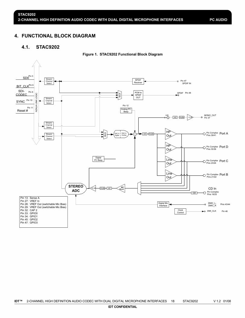
4.1. STAC9202Figure 1. STAC9202 Functional Block Diagram
MONO_OUTPin 37vol mute +0 dB
Pin ComplexPins 39/41
volStream/Channel Select
-6dBΣ
MU
X
Stream/Channel Select
SPDIF Receiver SPDIF IN
AZA
L IA
LI N
K L
OG
IC
mute
PCM to SPDIF OUTM
UX SPDIF
Pin 13: Sense APin 27: VREF InPin 28: VREF Out (switchable Mic Bias)Pin 29: VREF Out (switchable Mic Bias)Pin 32: CAP 2Pin 33: GPIO0Pin 34: GPIO1Pin 45: GPIO2Pin 47: GPIO3
Pin ComplexPins 35/36
Pin ComplexPins 23/24
Pin ComplexPins 21/22
Digital PC Beep
HPOut
LineOut
LineOut
HPOut
STEREOADC
volmute+22 dB
CD Pin ComplexPins 18/20
Stream/Channel Select
MICBoost
Stream/Channel Select
Port A
Port D
Port C
Port B
Pin 48
CD In
Pin 47SD0
BIT_CLKSDI-
CODEC
SYNC
Reset #
Pin 5
Pin 6
Pin 8
Pin 10
Pin 11
Σ
Analog PC Beep
Pin 12
DAC ADigital
DAC AAnalog
Digital Mic Interface
Clock Control Pin 46DMI_CLK
Pins 43/44DMIC_L, DMIC_R

STAC92022-CHANNEL HIGH DEFINITION AUDIO CODEC WITH DUAL DIGITAL MICROPHONE INTERFACES PC AUDIO
IDT™ 2-CHANNEL HIGH DEFINITION AUDIO CODEC WITH DUAL DIGITAL MICROPHONE INTERFACES 19 STAC9202 V 1.2 01/08
IDT CONFIDENTIAL
5. WIDGET DIAGRAM
5.1. STAC9202 Widget DiagramFigure 2. STAC9202 Widget Diagram
Aza
lia L
ink
SPDIF In Pin
7h
SPDIF OutPin
8h
Stereo Input
SPDIF IN
4h
Stereo ADC Input
3h
Stereo SPDIF Output
5h
Stereo DAC Output
2h
ADC Vol MuxV
olum
e
9h
SPDIFOut
SPDIF In
DAC
LR Swap
6h
0
1
1
0
2
Digital Analog
LR Swap
Volu
me/
Mut
e
Pin HP Out, LineOut,
LineIn, MIC
Ah
Pin HP Out, LineOut,
LineIn, MIC
Dh
Pin LineOut, LineIn,
MIC
Ch
Pin LineOut, LineIn,
MIC
Bh
Pin CD In
11h
PinMONO Out
10h
HP Out
Line Out
Line In
MIC
CD
MONO Out
HP: 0
HP: 0
Universal JackTM
Actual Pins 39/41
Universal JackTM
Actual Pins 35/36
Universal JackTM
Actual Pins 23/24
Universal JackTM
Actual Pins 21/22
Actual Pins 18/20
Actual Pin37
In P
ort M
ux
Fh
0, 10, 20, 30, 40dB Amp
Volu
me
Master Volume
Volu
me/
Mut
e
Eh
Actual Pin47
Actual Pin48
0 to -46.5
0 to +22.5
Digital PC Beep
13h
Port A
Port D
Port C
Port B
MonoMix
12h
Analog PC BeepPin 12
SD0 Pin 5
Bit CLK Pin 6
SDI Pin 8
SYNC Pin 10
Reset # Pin 11
Loop 3
Mixer
Pin 13: Sense APin 27: VREF InPin 28: VREF Out (switchable Mic Bias)Pin 32: CAP 2Pin 33: GPIO0Pin 34: GPIO1Pin 45: GPIO2Pin 47: GPIO3
3210
4
ADC In Mux
14h
Mut
e

STAC92022-CHANNEL HIGH DEFINITION AUDIO CODEC WITH DUAL DIGITAL MICROPHONE INTERFACES PC AUDIO
IDT™ 2-CHANNEL HIGH DEFINITION AUDIO CODEC WITH DUAL DIGITAL MICROPHONE INTERFACES 20 STAC9202 V 1.2 01/08
IDT CONFIDENTIAL
5.2. STAC9202 Widget List
Table 3. High Definition Audio Widget
ID Widget Name Description
00h Root Root Node
01h Audio Function Group Audio Function Group
02h DAC0 Stereo Ouput to DAC
03h ADC0 Stereo Input from ADC
04h SPDIF_IN Stereo Input for SPDIF_IN
05h SPDIF_OUT Stereo Output for SPDIF_OUT
06h DAC0Mux DAC Mux and Boost for outputs for DAC
07h DigPin1 Pin Widget for SPDIF_IN pin 47
08h DigPin0 Pin Widget for SPDIF_OUT pin 48
09h ADC0VolMux ADC0 Volume
0Eh MasterVolume Master Volume Controls
0Fh InPortMux Port Mux for ADC0
0Ah Port A Port A Pin Widget (Pins 39/41, configurable as HP, Line In, Line Out, Mic)
0Dh Port D Port D Pin Widget (Pins 35/36, configurable as HP, Line In, Line Out, Mic)
0Ch Port C Port C Pin Widget (Pins 23/24, configurable as Line Out, Mic)
0Bh Port B Port B Pin Widget (Pins 21/22, configurable as Line Out, Mic)
10h MonoOut Mono Output from DAC
11h CD CD Pin Widget pins 18/19/20
12h MonoOutMix Mixer for Mono Output
13h Digital PC Beep Digital PC Beep
14h ADC0InMux Input Mux for ADC converter
15h DigMicPin Pin Widget for Digital Microphone (Pins 43/44/46 configurable as a Mic)

STAC92022-CHANNEL HIGH DEFINITION AUDIO CODEC WITH DUAL DIGITAL MICROPHONE INTERFACES PC AUDIO
IDT™ 2-CHANNEL HIGH DEFINITION AUDIO CODEC WITH DUAL DIGITAL MICROPHONE INTERFACES 21 STAC9202 V 1.2 01/08
IDT CONFIDENTIAL
5.3. Root Node (NID = 0x00)
5.3.1. Root PnpID
5.3.2. Root RevID
Table 4. Root PnpID Command Verb Format
Verb ID Payload Response
Get F00 00 See bitfield table
Table 5. Root PnpID Command Response Format
Bit Bitfield Name RW Reset Description
[31:16] Vendor R 0x8384 Vendor ID = 8384h
[15:0] Device R 0x7630 Device ID for: STAC9202 = 7632
Table 6. Root RevID Command Verb Format
Verb ID Payload Response
Get F00 02 See bitfield table
Table 7. Root RevID Command Response Format
Bit Bitfield Name RW Reset Description
[31:24] Rsvd R 0x00 Reserved
[23:20] Major R 0x1 Major rev number of compliant HD Audio specification
[19:16] Minor R 0x0 Minor rev number of compliant HD Audio specification
[15:8] Vendor R 0x01 Vendor rev number for this device ID
[7:0] Stepping R 0x01 Vendor stepping number within the given Vendor RevID

STAC92022-CHANNEL HIGH DEFINITION AUDIO CODEC WITH DUAL DIGITAL MICROPHONE INTERFACES PC AUDIO
IDT™ 2-CHANNEL HIGH DEFINITION AUDIO CODEC WITH DUAL DIGITAL MICROPHONE INTERFACES 22 STAC9202 V 1.2 01/08
IDT CONFIDENTIAL
5.3.3. Root NodeInfo
5.4. AFG Node (NID = 0x01)
5.4.1. AFG Reset
Table 8. Root NodeInfo Command Verb Format
Verb ID Payload Response
Get F00 04 See bitfield table
Table 9. Root NodeInfo Command Response Format
Bit Bitfield Name RW Reset Description
[31:24] Rsvd2 R 0x00 Reserved
[23:16] StartNID R 0x01 Starting node number (NID) of first function group
[15:8] Rsvd1 R 0x00 Reserved
[7:0] TotalNodes R 0x01 Total number of nodes
Table 10. AFG Reset Command Verb Format
Verb ID Payload Response
Get 7FF 00 See bitfield table
Set1 7FF See bits [7:0] of bitfield table 0000_0000h

STAC92022-CHANNEL HIGH DEFINITION AUDIO CODEC WITH DUAL DIGITAL MICROPHONE INTERFACES PC AUDIO
IDT™ 2-CHANNEL HIGH DEFINITION AUDIO CODEC WITH DUAL DIGITAL MICROPHONE INTERFACES 23 STAC9202 V 1.2 01/08
IDT CONFIDENTIAL
5.4.2. AFG NodeInfo
Table 11. AFG Reset Command Response Format
Bit Bitfield Name RW Reset Description
[31:0] Response R 0x0 Reserved. Overlaps Execute.
[0] Execute W 0x0
Function Reset. Function Group reset is executed when the Set verb 7FF is written with 8-bit payload of 00h. The CODEC should issue a response to acknowledge receipt of the verb, and then reset the affected Function Group and all associated widgets to their power-on reset values. Some controls such as Configuration Default controls should not be reset. Overlaps Response.
Table 12. AFG NodeInfo Command Verb Format
Verb ID Payload Response
Get F00 04 See bitfield table
Table 13. AFG NodeInfo Command Response Format
Bit Bitfield Name RW Reset Description
[31:24] Rsvd2 R 0x0 Reserved
[23:16] StartNID R 0x02 Starting node number for function group subordinate nodes.
[15:8] Rsvd1 R 0x0 Reserved
[7:0] TotalNodes R 0x14 Total number of nodes. 14h = STAC9202

STAC92022-CHANNEL HIGH DEFINITION AUDIO CODEC WITH DUAL DIGITAL MICROPHONE INTERFACES PC AUDIO
IDT™ 2-CHANNEL HIGH DEFINITION AUDIO CODEC WITH DUAL DIGITAL MICROPHONE INTERFACES 24 STAC9202 V 1.2 01/08
IDT CONFIDENTIAL
5.4.3. AFG Type
5.4.4. AFG GrpCap
Table 14. AFG Type Command Verb Format
Verb ID Payload Response
Get F00 05 See bitfield table
Table 15. AFG Type Command Response Format
Bit Bitfield Name RW Reset Description
[31:9] Rsvd R 0x0 Reserved
[8] Unsol R 0x1
This node is capable of generating an unsolicited response, and will respond to the Unsolicited Response verb (Verb ID 708h).
[7:0] NodeType R 0x01 Node type = Audio Function Group
Table 16. AFG GrpCap Command Verb Format
Verb ID Payload Response
Get F00 08 See bitfield table
Table 17. AFG GrpCap Command Response Format
Bit Bitfield Name RW Reset Description
[31:17] Rsvd3 R 0x0 Reserved
[16] BeepGen R 0x1 Optional Beep Generator is present
[15:12] Rsvd2 R 0x0 Reserved
[11:8] InputDelay R 0xD
Typical latency = 13 frames. Number of samples between when the sample is received as an analog signal at the pin and when the digital representation is transmitted on the HD Audio link.

STAC92022-CHANNEL HIGH DEFINITION AUDIO CODEC WITH DUAL DIGITAL MICROPHONE INTERFACES PC AUDIO
IDT™ 2-CHANNEL HIGH DEFINITION AUDIO CODEC WITH DUAL DIGITAL MICROPHONE INTERFACES 25 STAC9202 V 1.2 01/08
IDT CONFIDENTIAL
5.4.5. AFG FrmtCap
[7:4] Rsvd1 R 0x0 Reserved
[3:0] OutputDelay R 0xD
Typical latency = 13 frames. Number of samples between when the signal is received from the HD Audio link and when it appears as an analog signal at the pin.
Table 18. AFG FrmtCap Command Verb Format
Verb ID Payload Response
Get F00 0A See bitfield table
Table 19. AFG FrmtCap Command Response Format
Bit Bitfield Name RW Reset Description
[31:21] Rsvd2 R 0x0 Reserved
[20] B32 R 0x0 32 bit audio formats are NOT supported
[19] B24 R 0x1 24 bit audio formats are supported
[18] B20 R 0x1 20 bit audio formats are supported
[17] B16 R 0x1 16 bit audio formats are supported
[16] B8 R 0x0 8 bit audio formats are NOT supported
[15:12] Rsvd1 R 0x0 Reserved
[11] R12 R 0x0 384 KHz rate (8/1*48 KHz) NOT supported
[10] R11 R 0x1 192.0 KHz rate (4/1*48 KHz) supported
[9] R10 R 0x1 176.4 KHz rate (4/1*44.1 KHz) supported
[8] R9 R 0x1 96.0 KHz rate (2/1*48 KHz) supported
[7] R8 R 0x1 88.2 KHz rate (2/1*44.1 KHz) supported
Table 17. AFG GrpCap Command Response Format
Bit Bitfield Name RW Reset Description

STAC92022-CHANNEL HIGH DEFINITION AUDIO CODEC WITH DUAL DIGITAL MICROPHONE INTERFACES PC AUDIO
IDT™ 2-CHANNEL HIGH DEFINITION AUDIO CODEC WITH DUAL DIGITAL MICROPHONE INTERFACES 26 STAC9202 V 1.2 01/08
IDT CONFIDENTIAL
5.4.6. AFG StreamCap
5.4.7. AFG PwrCap
[6] R7 R 0x1 48.0 KHz rate supported (REQUIRED)
[5] R6 R 0x1 44.1 KHz rate supported
[4] R5 R 0x0 32.0 KHz rate (2/3*48 KHz) NOT supported
[3] R4 R 0x0 22.05 KHz rate (1/2*44.1 KHz) NOT supported
[2] R3 R 0x0 16.0 KHz rate (1/3*48 KHz) NOT supported
[1] R2 R 0x0 11.025 KHz rate (1/4*44.0 KHz) NOT supported
[0] R1 R 0x0 8.0 KHz rate (1/6*48 KHz) NOT supported
Table 20. AFG StreamCap Command Verb Format
Verb ID Payload Response
Get F00 0B See bitfield table
Table 21. AFG StreamCap Command Response Format
Bit Bitfield Name RW Reset Description
[31:3] Rsvd R 0x0 Reserved
[2] NonPCM R 0x0 No support for non-PCM (AC3) data.
[1] Float32 R 0x0 No support for single-precision floating-point data.
[0] PCM R 0x1 PCM-formatted data supported.
Table 22. AFG PwrCap Command Verb Format
Verb ID Payload Response
Get F00 0F See bitfield table
Table 19. AFG FrmtCap Command Response Format
Bit Bitfield Name RW Reset Description

STAC92022-CHANNEL HIGH DEFINITION AUDIO CODEC WITH DUAL DIGITAL MICROPHONE INTERFACES PC AUDIO
IDT™ 2-CHANNEL HIGH DEFINITION AUDIO CODEC WITH DUAL DIGITAL MICROPHONE INTERFACES 27 STAC9202 V 1.2 01/08
IDT CONFIDENTIAL
5.4.8. AFG GPIOCap
Table 23. AFG PwrCap Command Response Format
Bit Bitfield Name RW Reset Description
[31:4] Rsvd R 0x0 Reserved
[3] D3 R 0x1
Power State D3 is supported. Allows for lowest possible power consuming state under software control (and still properly respond to a subsequent Power State command).
[2] D2 R 0x1
Power State D2 is supported. Allows for lowest possible power consuming state from which it can return to fully on state within 10 ms.
[1] D1 R 0x1
Power State D1 is supported. Allows for lowest possible power consuming state from which it can return to fully on state within 10 ms, excepting analog pass-through circuits which must remain fully on.
[0] D0 R 0x1 Power State D0 is supported. Node power state is fully on.
Table 24. AFG GPIOCap Command Verb Format
Verb ID Payload Response
Get F00 11 See bitfield table

STAC92022-CHANNEL HIGH DEFINITION AUDIO CODEC WITH DUAL DIGITAL MICROPHONE INTERFACES PC AUDIO
IDT™ 2-CHANNEL HIGH DEFINITION AUDIO CODEC WITH DUAL DIGITAL MICROPHONE INTERFACES 28 STAC9202 V 1.2 01/08
IDT CONFIDENTIAL
5.4.9. AFG OutAmpCap
Table 25. AFG GPIOCap Command Response Format
Bit Bitfield Name RW Reset Description
[31] GPIWake R 0x1
Wake capability. Assuming the Wake Enable Mask controls are enabled, GPIOs configured as inputs can cause a wake (generate a Status Change event on the link) when there is a change in level on the pin.
[30] GPIUnsol R 0x1
Unsolicited Response capability. Assuming the Unsolicited Enable Mask controls are enabled, GPIOs configured as inputs can generate an Unsolicited Response on the link when there is a change in level on the pin.
[29:24] Rsvd R 0x0 Reserved
[23:16] NumGPIs R 0x00 Number of GPI pins supported
[15:8] NumGPOs R 0x00 Number of GPO pins supported
[7:0] NumGPIOs R 0x04 Number of GPIO pins supported
Table 26. AFG OutAmpCap Command Verb Format
Verb ID Payload Response
Get F00 12 See bitfield table
Table 27. AFG OutAmpCap Command Response Format
Bit Bitfield Name RW Reset Description
[31] Mute R 0x1 Amplifier is capable of muting
[30:23] Rsvd3 R 0x0 Reserved
[22:16] StepSize R 0x05 Size of each step in the gain range = 1.5dB
[15] Rsvd2 R 0x0 Reserved

STAC92022-CHANNEL HIGH DEFINITION AUDIO CODEC WITH DUAL DIGITAL MICROPHONE INTERFACES PC AUDIO
IDT™ 2-CHANNEL HIGH DEFINITION AUDIO CODEC WITH DUAL DIGITAL MICROPHONE INTERFACES 29 STAC9202 V 1.2 01/08
IDT CONFIDENTIAL
5.4.10. AFG PwrState
5.4.11. AFG UnsolResp
[14:8] NumSteps R 0x1F Number of steps in the gain range = 31 (32 values, -46.5dB to +0dB)
[7] Rsvd1 R 0x0 Reserved
[6:0] Offset R 0x1F 0dB-step is programmed with this offset
Table 28. AFG PwrState Command Verb Format
Verb ID Payload Response
Get F05 00 See bitfield table
Set1 705 See bits [7:0] of bitfield table 0000_0000h
Table 29. AFG PwrState Command Response Format
Bit Bitfield Name RW Reset Description
[31:8] Rsvd2 R 0x0 Reserved
[7:4] Act R 0x2 PS-Act: Actual power state of referenced node.
[3:2] Rsvd1 R 0x0 Reserved
[1:0] Set RW 0x2
PS-Set: Current power setting of referenced node. 0: All Powered-On 1: D1 = > PR0, PR1 2: D2 = > PR0, PR1, PR2, PR6, EAPD 3: D3 = > PR6, PR5, PR3, PR2, PR1, PR0, EAPD Note: PR4 is not mapped in HD Audio
Table 30. AFG UnsolResp Command Verb Format
Verb ID Payload Response
Get F08 00 See bitfield table
Set1 708 See bits [7:0] of bitfield table 0000_0000h
Table 27. AFG OutAmpCap Command Response Format
Bit Bitfield Name RW Reset Description

STAC92022-CHANNEL HIGH DEFINITION AUDIO CODEC WITH DUAL DIGITAL MICROPHONE INTERFACES PC AUDIO
IDT™ 2-CHANNEL HIGH DEFINITION AUDIO CODEC WITH DUAL DIGITAL MICROPHONE INTERFACES 30 STAC9202 V 1.2 01/08
IDT CONFIDENTIAL
5.4.12. AFG GPIO
Table 31. AFG UnsolResp Command Response Format
Bit Bitfield Name RW Reset Description
[31:8] Rsvd2 R 0x0 Reserved
[7] En RW 0x0 Allow generation of Unsolicited Responses.
[6] Rsvd1 R 0x0 Reserved
[5:0] Tag RW 0x0Software programmable field returned in top six bits (31:26) of every Unsolicited Response generated by this node.
Table 32. AFG GPIO Command Verb Format
Verb ID Payload Response
Get F15 00 See bitfield table
Set1 715 See bits [7:0] of bitfield table 0000_0000h
Table 33. AFG GPIO Command Response Format
Bit Bitfield Name RW Reset Description
[31:4] Rsvd R 0x0 Reserved
[3] Data3 RW 0x0
Data for GPIO3 (Pin 47/EAPD). If this GPIO bit is configured as Sticky (edge-sensitive) input, it can be cleared by writing zero (one) here when the corresponding Polarity Control bit is zero (one).
[2] Data2 RW 0x0
Data for GPIO2 (Pin 45). If this GPIO bit is configured as Sticky (edge-sensitive) input, it can be cleared by writing zero (one) here when the corresponding Polarity Control bit is zero (one).

STAC92022-CHANNEL HIGH DEFINITION AUDIO CODEC WITH DUAL DIGITAL MICROPHONE INTERFACES PC AUDIO
IDT™ 2-CHANNEL HIGH DEFINITION AUDIO CODEC WITH DUAL DIGITAL MICROPHONE INTERFACES 31 STAC9202 V 1.2 01/08
IDT CONFIDENTIAL
5.4.13. AFG GPIOEn
[1] Data1 RW 0x0
Data for GPIO1 (Pin 34). If this GPIO bit is configured as Sticky (edge-sensitive) input, it can be cleared by writing zero (one) here when the corresponding Polarity Control bit is zero (one).
[0] Data0 RW 0x0
Data for GPIO0 (Pin 33). If this GPIO bit is configured as Sticky (edge-sensitive) input, it can be cleared by writing zero (one) here when the corresponding Polarity Control bit is zero (one).
Table 34. AFG GPIOEn Command Verb Format
Verb ID Payload Response
Get F16 00 See bitfield table
Set1 716 See bits [7:0] of bitfield table 0000_0000h
Table 35. AFG GPIOEn Command Response Format
Bit Bitfield Name RW Reset Description
[31:4] Rsvd R 0x0 Reserved
[3] Mask3 RW 0x0
Enable for GPIO3: 0 = pin is disabled (Hi-Z state); 1 = pin is enabled; behavior determined by GPIO Direction control
[2] Mask2 RW 0x0
Enable for GPIO2: 0 = pin is disabled (Hi-Z state); 1 = pin is enabled; behavior determined by GPIO Direction control
Table 33. AFG GPIO Command Response Format
Bit Bitfield Name RW Reset Description
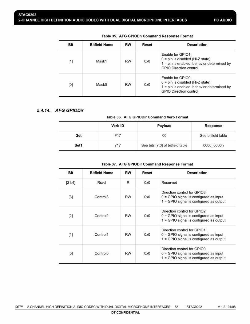
STAC92022-CHANNEL HIGH DEFINITION AUDIO CODEC WITH DUAL DIGITAL MICROPHONE INTERFACES PC AUDIO
IDT™ 2-CHANNEL HIGH DEFINITION AUDIO CODEC WITH DUAL DIGITAL MICROPHONE INTERFACES 32 STAC9202 V 1.2 01/08
IDT CONFIDENTIAL
5.4.14. AFG GPIODir
[1] Mask1 RW 0x0
Enable for GPIO1: 0 = pin is disabled (Hi-Z state); 1 = pin is enabled; behavior determined by GPIO Direction control
[0] Mask0 RW 0x0
Enable for GPIO0: 0 = pin is disabled (Hi-Z state); 1 = pin is enabled; behavior determined by GPIO Direction control
Table 36. AFG GPIODir Command Verb Format
Verb ID Payload Response
Get F17 00 See bitfield table
Set1 717 See bits [7:0] of bitfield table 0000_0000h
Table 37. AFG GPIODir Command Response Format
Bit Bitfield Name RW Reset Description
[31:4] Rsvd R 0x0 Reserved
[3] Control3 RW 0x0Direction control for GPIO3 0 = GPIO signal is configured as input 1 = GPIO signal is configured as output
[2] Control2 RW 0x0Direction control for GPIO2 0 = GPIO signal is configured as input 1 = GPIO signal is configured as output
[1] Control1 RW 0x0Direction control for GPIO1 0 = GPIO signal is configured as input 1 = GPIO signal is configured as output
[0] Control0 RW 0x0Direction control for GPIO0 0 = GPIO signal is configured as input 1 = GPIO signal is configured as output
Table 35. AFG GPIOEn Command Response Format
Bit Bitfield Name RW Reset Description

STAC92022-CHANNEL HIGH DEFINITION AUDIO CODEC WITH DUAL DIGITAL MICROPHONE INTERFACES PC AUDIO
IDT™ 2-CHANNEL HIGH DEFINITION AUDIO CODEC WITH DUAL DIGITAL MICROPHONE INTERFACES 33 STAC9202 V 1.2 01/08
IDT CONFIDENTIAL
5.4.15. AFG GPIOWake
5.4.16. AFG GPIOUnsolEn
Table 38. AFG GPIOWake Command Verb Format
Verb ID Payload Response
Get F18 00 See bitfield table
Set1 718 See bits [7:0] of bitfield table 0000_0000h
Table 39. AFG GPIOWake Command Response Format
Bit Bitfield Name RW Reset Description
[31:4] Rsvd R 0x0 Reserved
[3] En3 RW 0x0
Wake enable for GPIO3: 0 = wake-up event is disabled; 1 = when HD Audio link is powered down (RST# is asserted), a wake-up event will trigger a Status Change Request event on the link.
[2] En2 RW 0x0
Wake enable for GPIO2: 0 = wake-up event is disabled; 1 = when HD Audio link is powered down (RST# is asserted), a wake-up event will trigger a Status Change Request event on the link.
[1] En1 RW 0x0
Wake enable for GPIO1: 0 = wake-up event is disabled; 1 = when HD Audio link is powered down (RST# is asserted), a wake-up event will trigger a Status Change Request event on the link.
[0] En0 RW 0x0
Wake enable for GPIO0: 0 = wake-up event is disabled; 1 = when HD Audio link is powered down (RST# is asserted), a wake-up event will trigger a Status Change Request event on the link.
Table 40. AFG GPIOUnsolEn Command Verb Format
Verb ID Payload Response
Get F19 00 See bitfield table
Set1 719 See bits [7:0] of bitfield table 0000_0000h

STAC92022-CHANNEL HIGH DEFINITION AUDIO CODEC WITH DUAL DIGITAL MICROPHONE INTERFACES PC AUDIO
IDT™ 2-CHANNEL HIGH DEFINITION AUDIO CODEC WITH DUAL DIGITAL MICROPHONE INTERFACES 34 STAC9202 V 1.2 01/08
IDT CONFIDENTIAL
5.4.17. AFG GPIOSticky
Table 41. AFG GPIOUnsolEn Command Response Format
Bit Bitfield Name RW Reset Description
[31:4] Rsvd R 0x0 Reserved
[3] Mask3 RW 0x0
Unsolicited enable mask for GPIO3. If set, and the Unsolicited Response control for this widget has been enabled, an unsolicited response will be sent when GPIO3 is configured as input and changes state.
[2] Mask2 RW 0x0
Unsolicited enable mask for GPIO2. If set, and the Unsolicited Response control for this widget has been enabled, an unsolicited response will be sent when GPIO2 is configured as input and changes state.
[1] Mask1 RW 0x0
Unsolicited enable mask for GPIO1. If set, and the Unsolicited Response control for this widget has been enabled, an unsolicited response will be sent when GPIO1 is configured as input and changes state.
[0] Mask0 RW 0x0
Unsolicited enable mask for GPIO0. If set, and the Unsolicited Response control for this widget has been enabled, an unsolicited response will be sent when GPIO0 is configured as input and changes state.
Table 42. AFG GPIOSticky Command Verb Format
Verb ID Payload Response
Get F1A 00 See bitfield table
Set1 71A See bits [7:0] of bitfield table 0000_0000h

STAC92022-CHANNEL HIGH DEFINITION AUDIO CODEC WITH DUAL DIGITAL MICROPHONE INTERFACES PC AUDIO
IDT™ 2-CHANNEL HIGH DEFINITION AUDIO CODEC WITH DUAL DIGITAL MICROPHONE INTERFACES 35 STAC9202 V 1.2 01/08
IDT CONFIDENTIAL
5.4.18. AFG SysID
Table 43. AFG GPIOSticky Command Response Format
Bit Bitfield Name RW Reset Description
[31:4] Rsvd R 0x0 Reserved
[3] Mask3 RW 0x0
GPIO3 input type (when configured as input): 0 = Non-Sticky (level-sensitive)1 = Sticky (edge-sensitive)Sticky inputs are cleared by writing zero to corresponding bit of GPIO Data register. GPIOPolarity determines rising or falling edge sensitivity.
[2] Mask2 RW 0x0
GPIO2input type (when configured as input): 0 = Non-Sticky (level-sensitive)1 = Sticky (edge-sensitive)Sticky inputs are cleared by writing zero to corresponding bit of GPIO Data register. GPIOPolarity determines rising or falling edge sensitivity.
[1] Mask1 RW 0x0
GPIO1input type (when configured as input): 0 = Non-Sticky (level-sensitive)1 = Sticky (edge-sensitive)Sticky inputs are cleared by writing zero to corresponding bit of GPIO Data register. GPIOPolarity determines rising or falling edge sensitivity.
[0] Mask0 RW 0x0
GPIO0input type (when configured as input): 0 = Non-Sticky (level-sensitive)1 = Sticky (edge-sensitive)Sticky inputs are cleared by writing zero to corresponding bit of GPIO Data register. GPIOPolarity determines rising or falling edge sensitivity.
Table 44. AFG SysID Command Verb Format
Verb ID Payload Response
Get F20 00 See bitfield table
Set1 720 See bits [7:0] of bitfield table 0000_0000h
Set2 721 See bits [15:8] of bitfield table 0000_0000h
Set3 722 See bits [23:16] of bitfield table 0000_0000h
Set4 723 See bits [31:24] of bitfield table 0000_0000h

STAC92022-CHANNEL HIGH DEFINITION AUDIO CODEC WITH DUAL DIGITAL MICROPHONE INTERFACES PC AUDIO
IDT™ 2-CHANNEL HIGH DEFINITION AUDIO CODEC WITH DUAL DIGITAL MICROPHONE INTERFACES 36 STAC9202 V 1.2 01/08
IDT CONFIDENTIAL
5.4.19. AFG DigMic
Table 45. AFG SysID Command Response Format
Bit Bitfield Name RW Reset Description
[31:24] Subsystem3 RW 0x00 Subsystem ID. (Any non-zero value)
[23:16] Subsystem2 RW 0x00 Subsystem ID. (Any non-zero value)
[15:8] Subsystem1 RW 0x01 Subsystem ID. (Any non-zero value)
[7:0] Assembly RW 0x00 Assembly ID. (Not applicable to CODEC vendors)
Table 46. AFG DigMic Command Verb Format
Verb ID Payload Response
Get FEA 00 See bitfield table
Set1 7EA See bits [7:0] of bitfield table 0000_0000h
Table 47. AFG DigMic Command Response Format
Bit Bitfield Name RW Reset Description
[31:8] Rsvd R 0x0 Reserved
[7:6] PhAdj RW 0x0
Selects what phase of the DigMic clock the data should be latched: 0 = rising edge1 = center of high2 = falling edge3 = center of low
[5:4] Rate RW 0x2
Selects the DigMic rate: 0 = 4 MHz1 = 3 MHz2 = 2 MHz3 = 1 MHz
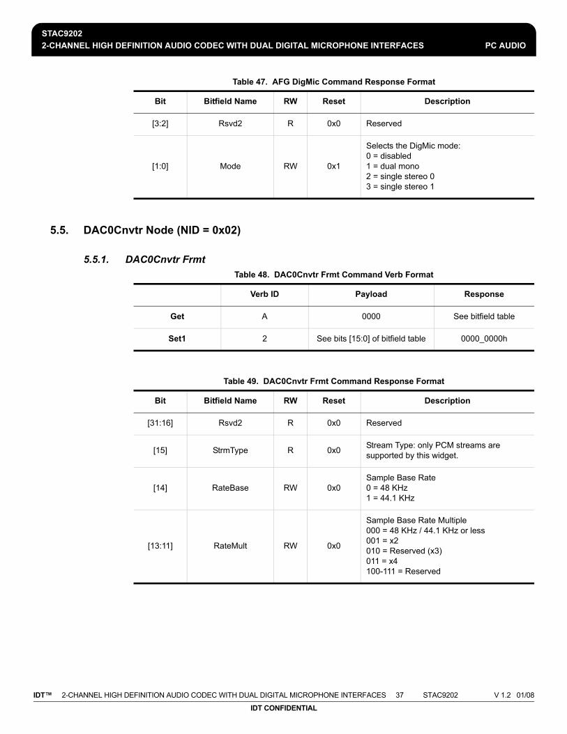
STAC92022-CHANNEL HIGH DEFINITION AUDIO CODEC WITH DUAL DIGITAL MICROPHONE INTERFACES PC AUDIO
IDT™ 2-CHANNEL HIGH DEFINITION AUDIO CODEC WITH DUAL DIGITAL MICROPHONE INTERFACES 37 STAC9202 V 1.2 01/08
IDT CONFIDENTIAL
5.5. DAC0Cnvtr Node (NID = 0x02)
5.5.1. DAC0Cnvtr Frmt
[3:2] Rsvd2 R 0x0 Reserved
[1:0] Mode RW 0x1
Selects the DigMic mode: 0 = disabled1 = dual mono2 = single stereo 03 = single stereo 1
Table 48. DAC0Cnvtr Frmt Command Verb Format
Verb ID Payload Response
Get A 0000 See bitfield table
Set1 2 See bits [15:0] of bitfield table 0000_0000h
Table 49. DAC0Cnvtr Frmt Command Response Format
Bit Bitfield Name RW Reset Description
[31:16] Rsvd2 R 0x0 Reserved
[15] StrmType R 0x0 Stream Type: only PCM streams are supported by this widget.
[14] RateBase RW 0x0Sample Base Rate 0 = 48 KHz 1 = 44.1 KHz
[13:11] RateMult RW 0x0
Sample Base Rate Multiple 000 = 48 KHz / 44.1 KHz or less 001 = x2 010 = Reserved (x3) 011 = x4 100-111 = Reserved
Table 47. AFG DigMic Command Response Format
Bit Bitfield Name RW Reset Description

STAC92022-CHANNEL HIGH DEFINITION AUDIO CODEC WITH DUAL DIGITAL MICROPHONE INTERFACES PC AUDIO
IDT™ 2-CHANNEL HIGH DEFINITION AUDIO CODEC WITH DUAL DIGITAL MICROPHONE INTERFACES 38 STAC9202 V 1.2 01/08
IDT CONFIDENTIAL
5.5.2. DAC0Cnvtr WCap
[10:8] RateDiv RW 0x0
Sample Base Rate Divisor 000 = Divide by 1 001 = Divide by 2 010 = Divide by 3 011 = Divide by 4 100 = Divide by 5 101 = Divide by 6 110 = Divide by 7 111 = Divide by 8
[7] Rsvd1 R 0x0 Reserved
[6:4] NumBits RW 0x3
Bits per Sample: 000 = 8 bits 001 = 16 bits 010 = 20 bits 011 = 24 bits 100-111 = Reserved
[3:0] NumChan RW 0x1
Number of Channels in each frame of the stream.0000 = 1 channel 0001 = 2 channels ... 1111 = 16 channels
Table 50. DAC0Cnvtr WCap Command Verb Format
Verb ID Payload Response
Get F00 09 See bitfield table
Table 51. DAC0Cnvtr WCap Command Response Format
Bit Bitfield Name RW Reset Description
[31:24] Rsvd2 R 0x0 Reserved
[23:20] Type R 0x0 Widget type = Audio Output
[19:16] Delay R 0xD Number of sample delays through widget
[15:12] Rsvd1 R 0x0 Reserved
Table 49. DAC0Cnvtr Frmt Command Response Format
Bit Bitfield Name RW Reset Description

STAC92022-CHANNEL HIGH DEFINITION AUDIO CODEC WITH DUAL DIGITAL MICROPHONE INTERFACES PC AUDIO
IDT™ 2-CHANNEL HIGH DEFINITION AUDIO CODEC WITH DUAL DIGITAL MICROPHONE INTERFACES 39 STAC9202 V 1.2 01/08
IDT CONFIDENTIAL
5.5.3. DAC0Cnvtr PwrState
[11] SwapCap R 0x0 No left/right channel swap capability
[10] PwrCntrl R 0x1 Power State control is supported
[9] DigitalStrm R 0x0 Widget supports an Analog stream
[8] ConnList R 0x0 No connection list is present
[7] UnsolCap R 0x0 No support for Unsolicited Response
[6] ProcWidget R 0x0 No Processing Controls parameter
[5] Stripe R 0x0 No support for striping
[4] FormatOvrd R 0x0 No format info; use default format parameters from Audio Function node instead
[3] AmpParamOvrd R 0x0 No amplifier info; use default amplifier parameters from Audio Function node instead
[2] OutAmpPrsnt R 0x0 No output amp
[1] InAmpPrsnt R 0x0 No input amp
[0] Stereo R 0x1 Stereo widget
Table 52. DAC0Cnvtr PwrState Command Verb Format
Verb ID Payload Response
Get F05 00 See bitfield table
Set1 705 See bits [7:0] of bitfield table 0000_0000h
Table 53. DAC0Cnvtr PwrState Command Response Format
Bit Bitfield Name RW Reset Description
[31:8] Rsvd2 R 0x0 Reserved
[7:4] Act R 0x3 PS-Act: Actual power state of referenced node.
Table 51. DAC0Cnvtr WCap Command Response Format
Bit Bitfield Name RW Reset Description

STAC92022-CHANNEL HIGH DEFINITION AUDIO CODEC WITH DUAL DIGITAL MICROPHONE INTERFACES PC AUDIO
IDT™ 2-CHANNEL HIGH DEFINITION AUDIO CODEC WITH DUAL DIGITAL MICROPHONE INTERFACES 40 STAC9202 V 1.2 01/08
IDT CONFIDENTIAL
5.5.4. DAC0Cnvtr Stream
[3:2] Rsvd1 R 0x0 Reserved
[1:0] Set RW 0x3
PS-Set: Current power setting of referenced node. 00 - Fully on. 01 - Fully on. 10 - Fully on. 11 - Powered down.
Table 54. DAC0Cnvtr Stream Command Verb Format
Verb ID Payload Response
Get F06 00 See bitfield table
Set1 706 See bits [7:0] of bitfield table 0000_0000h
Table 55. DAC0Cnvtr Stream Command Response Format
Bit Bitfield Name RW Reset Description
[31:8] Rsvd R 0x0 Reserved
[7:4] ID RW 0x0Software-programmable integer representing link stream ID used by the converter widget. By convention stream 0 is reserved as unused.
[3:0] Ch RW 0x0 Integer representing lowest channel used by converter.
Table 53. DAC0Cnvtr PwrState Command Response Format
Bit Bitfield Name RW Reset Description

STAC92022-CHANNEL HIGH DEFINITION AUDIO CODEC WITH DUAL DIGITAL MICROPHONE INTERFACES PC AUDIO
IDT™ 2-CHANNEL HIGH DEFINITION AUDIO CODEC WITH DUAL DIGITAL MICROPHONE INTERFACES 41 STAC9202 V 1.2 01/08
IDT CONFIDENTIAL
5.6. ADC0Cnvtr Node (NID = 0x03)
5.6.1. ADC0Cnvtr Frmt Table 56. ADC0Cnvtr Frmt Command Verb Format
Verb ID Payload Response
Get A 0000 See bitfield table
Set1 2 See bits [15:0] of bitfield table 0000_0000h
Table 57. ADC0Cnvtr Frmt Command Response Format
Bit Bitfield Name RW Reset Description
[31:16] Rsvd2 R 0x0 Reserved
[15] StrmType RW 0x0
Stream Type 0 = PCM 1 = Non-PCM (remaining bits in this verb have other meanings)
[14] RateBase RW 0x0Sample Base Rate 0 = 48 KHz 1 = 44.1 KHz
[13:11] RateMult RW 0x0
Sample Base Rate Multiple 000 = 48 KHz / 44.1 KHz or less 001 = x2 010 = Reserved (x3) 011 = x4 100-111 = Reserved
[10:8] RateDiv RW 0x0
Sample Base Rate Divisor 000 = Divide by 1 001 = Divide by 2 010 = Divide by 3 011 = Divide by 4 100 = Divide by 5 101 = Divide by 6 110 = Divide by 7 111 = Divide by 8
[7] Rsvd1 R 0x0 Reserved

STAC92022-CHANNEL HIGH DEFINITION AUDIO CODEC WITH DUAL DIGITAL MICROPHONE INTERFACES PC AUDIO
IDT™ 2-CHANNEL HIGH DEFINITION AUDIO CODEC WITH DUAL DIGITAL MICROPHONE INTERFACES 42 STAC9202 V 1.2 01/08
IDT CONFIDENTIAL
5.6.2. ADC0Cnvtr WCap
[6:4] NumBits RW 0x3
Bits per Sample 000 = 8 bits 001 = 16 bits 010 = 20 bits 011 = 24 bits 100-111 = Reserved
[3:0] NumChan RW 0x1
Number of Channels in each frame of the stream. 0000 = 1 channel 0001 = 2 channels ... 1111 = 16 channels
Table 58. ADC0Cnvtr WCap Command Verb Format
Verb ID Payload Response
Get F00 09 See bitfield table
Table 59. ADC0Cnvtr WCap Command Response Format
Bit Bitfield Name RW Reset Description
[31:24] Rsvd2 R 0x0 Reserved
[23:20] Type R 0x1 Widget type = Audio Input
[19:16] Delay R 0xD Number of sample delays through widget
[15:12] Rsvd1 R 0x0 Reserved
[11] SwapCap R 0x0 No left/right channel swap capability
[10] PwrCntrl R 0x1 Power State control is supported
[9] DigitalStrm R 0x0 Widget supports an Analog stream
[8] ConnList R 0x1 Connection list is present
[7] UnsolCap R 0x0 No support for Unsolicited Response
Table 57. ADC0Cnvtr Frmt Command Response Format
Bit Bitfield Name RW Reset Description

STAC92022-CHANNEL HIGH DEFINITION AUDIO CODEC WITH DUAL DIGITAL MICROPHONE INTERFACES PC AUDIO
IDT™ 2-CHANNEL HIGH DEFINITION AUDIO CODEC WITH DUAL DIGITAL MICROPHONE INTERFACES 43 STAC9202 V 1.2 01/08
IDT CONFIDENTIAL
5.6.3. ADC0Cnvtr ConnLen
[6] ProcWidget R 0x1 Software should query the Processing Controls parameter for this widget.
[5] Stripe R 0x0 No support for striping
[4] FormatOvrd R 0x0No format info; use default format parameters from Audio Function node instead
[3] AmpParamOvrd R 0x0No amplifier info; use default amplifier parameters from Audio Function node instead
[2] OutAmpPrsnt R 0x0 No output amp
[1] InAmpPrsnt R 0x0 No input amp
[0] Stereo R 0x1 Stereo widget
Table 60. ADC0Cnvtr ConnLen Command Verb Format
Verb ID Payload Response
Get F00 0E See bitfield table
Table 61. ADC0Cnvtr ConnLen Command Response Format
Bit Bitfield Name RW Reset Description
[31:8] Rsvd R 0x0 Reserved.
[7] LongForm R 0x0 Connection list uses short-form (7-bit) NID entries.
[6:0] N R 0x01 Number of NID entries in connection list.
Table 59. ADC0Cnvtr WCap Command Response Format
Bit Bitfield Name RW Reset Description

STAC92022-CHANNEL HIGH DEFINITION AUDIO CODEC WITH DUAL DIGITAL MICROPHONE INTERFACES PC AUDIO
IDT™ 2-CHANNEL HIGH DEFINITION AUDIO CODEC WITH DUAL DIGITAL MICROPHONE INTERFACES 44 STAC9202 V 1.2 01/08
IDT CONFIDENTIAL
5.6.4. ADC0Cnvtr ConnLst
5.6.5. ADC0Cnvtr ProcState
Table 62. ADC0Cnvtr ConnLst Command Verb Format
Verb ID Payload Response
Get F02 00 See bitfield table
Table 63. ADC0Cnvtr ConnLst Command Response Format
Bit Bitfield Name RW Reset Description
[31:24] Entry3 R 0x00 Unused list entry.
[23:16] Entry2 R 0x00 Unused list entry.
[15:8] Entry1 R 0x00 Unused list entry.
[7:0] Entry0 R 0x14 ADC0InMux
Table 64. ADC0Cnvtr ProcState Command Verb Format
Verb ID Payload Response
Get F03 00 See bitfield table
Set1 703 See bits [7:0] of bitfield table 0000_0000h
Table 65. ADC0Cnvtr ProcState Command Response Format
Bit Bitfield Name RW Reset Description
[31:8] Rsvd2 R 0x0 Reserved
[7] HPFOffsetDis RW 0x0High Pass Filter Offset Calculation Disable 0 = Calculation enabled. 1 = Calculation disabled.
[6:2] Rsvd1 R 0x0 Reserved
[1:0] HPFByp RW 0x1
Processing State = 00 (OFF): bypass the ADC high pass filter; Processing State = 01, 10, 11 (ON or BENIGN): ADC high pass filter is enabled.

STAC92022-CHANNEL HIGH DEFINITION AUDIO CODEC WITH DUAL DIGITAL MICROPHONE INTERFACES PC AUDIO
IDT™ 2-CHANNEL HIGH DEFINITION AUDIO CODEC WITH DUAL DIGITAL MICROPHONE INTERFACES 45 STAC9202 V 1.2 01/08
IDT CONFIDENTIAL
5.6.6. ADC0Cnvtr PwrState
5.6.7. ADC0Cnvtr Stream
Table 66. ADC0Cnvtr PwrState Command Verb Format
Verb ID Payload Response
Get F05 00 See bitfield table
Set1 705 See bits [7:0] of bitfield table 0000_0000h
Table 67. ADC0Cnvtr PwrState Command Response Format
Bit Bitfield Name RW Reset Description
[31:8] Rsvd2 R 0x0 Reserved
[7:4] Act R 0x3 PS-Act: Actual power state of referenced node.
[3:2] Rsvd1 R 0x0 Reserved
[1:0] Set RW 0x3
PS-Set: Current power setting of referenced node. 00 - Fully on. 01 - Fully on. 10 - Fully on. 11 - Powered down (default powered down)
Table 68. ADC0Cnvtr Stream Command Verb Format
Verb ID Payload Response
Get F06 00 See bitfield table
Set1 706 See bits [7:0] of bitfield table 0000_0000h
Table 69. ADC0Cnvtr Stream Command Response Format
Bit Bitfield Name RW Reset Description
[31:8] Rsvd R 0x0 Reserved

STAC92022-CHANNEL HIGH DEFINITION AUDIO CODEC WITH DUAL DIGITAL MICROPHONE INTERFACES PC AUDIO
IDT™ 2-CHANNEL HIGH DEFINITION AUDIO CODEC WITH DUAL DIGITAL MICROPHONE INTERFACES 46 STAC9202 V 1.2 01/08
IDT CONFIDENTIAL
5.7. SPDIFinCnvtr Node (NID = 0x04)
5.7.1. SPDIFinCnvtr Frmt
[7:4] ID RW 0x0Software-programmable integer representing link stream ID used by the converter widget. By convention stream 0 is reserved as unused.
[3:0] Ch RW 0x0 Integer representing lowest channel used by converter
Table 70. SPDIFinCnvtr Frmt Command Verb Format
Verb ID Payload Response
Get A 0000 See bitfield table
Set1 2 See bits [15:0] of bitfield table 0000_0000h
Table 71. SPDIFinCnvtr Frmt Command Response Format
Bit Bitfield Name RW Reset Description
[31:16] Rsvd2 R 0x0 Reserved
[15] StrmType RW 0x0
N/A.(Stream Type 0 = PCM 1 = Non-PCM)
[14] RateBase RW 0x0Sample Base Rate 0 = 48 KHz 1 = 44.1 KHz
[13:11] RateMult RW 0x0
Sample Base Rate Multiple 000 = 48 KHz / 44.1 KHz or less 001 = x2 010 = Reserved (x3) 011 = x4 100-111 = Reserved
Table 69. ADC0Cnvtr Stream Command Response Format
Bit Bitfield Name RW Reset Description

STAC92022-CHANNEL HIGH DEFINITION AUDIO CODEC WITH DUAL DIGITAL MICROPHONE INTERFACES PC AUDIO
IDT™ 2-CHANNEL HIGH DEFINITION AUDIO CODEC WITH DUAL DIGITAL MICROPHONE INTERFACES 47 STAC9202 V 1.2 01/08
IDT CONFIDENTIAL
5.7.2. SPDIFinCnvtr WCap
[10:8] RateDiv RW 0x0
Sample Base Rate Divisor 000 = Divide by 1 001 = Divide by 2 010 = Divide by 3 011 = Divide by 4 100 = Divide by 5 101 = Divide by 6 110 = Divide by 7 111 = Divide by 8
[7] Rsvd1 R 0x0 Reserved
[6:4] NumBits RW 0x3
Bits per Sample 000 = 8 bits 001 = 16 bits 010 = 20 bits 011 = 24 bits 100-111 = Reserved
[3:0] NumChan RW 0x1
Number of Channels in each frame of the stream. 0000 = 1 channel 0001 = 2 channels... 1111 = 16 channels
Table 72. SPDIFinCnvtr WCap Command Verb Format
Verb ID Payload Response
Get F00 09 See bitfield table
Table 73. SPDIFinCnvtr WCap Command Response Format
Bit Bitfield Name RW Reset Description
[31:24] Rsvd2 R 0x0 Reserved
[23:20] Type R 0x1 Widget type = Audio Input
[19:16] Delay R 0x4 Number of sample delays through widget
[15:12] Rsvd1 R 0x0 Reserved
Table 71. SPDIFinCnvtr Frmt Command Response Format
Bit Bitfield Name RW Reset Description

STAC92022-CHANNEL HIGH DEFINITION AUDIO CODEC WITH DUAL DIGITAL MICROPHONE INTERFACES PC AUDIO
IDT™ 2-CHANNEL HIGH DEFINITION AUDIO CODEC WITH DUAL DIGITAL MICROPHONE INTERFACES 48 STAC9202 V 1.2 01/08
IDT CONFIDENTIAL
5.7.3. SPDIFinCnvtr FrmtCap
[11] SwapCap R 0x0 No left/right channel swap capability
[10] PwrCntrl R 0x0 No support for Power State control
[9] DigitalStrm R 0x1 Widget supports a Digital stream
[8] ConnList R 0x1 Connection list is present
[7] UnsolCap R 0x0 No support for Unsolicited Response
[6] ProcWidget R 0x0 No Processing Controls parameter
[5] Stripe R 0x0 No support for striping
[4] FormatOvrd R 0x1 Widget contains format info; software should query
[3] AmpParamOvrd R 0x0 No amplifier info; use default amplifier parameters from Audio Function node instead
[2] OutAmpPrsnt R 0x0 No output amp
[1] InAmpPrsnt R 0x0 No input amp
[0] Stereo R 0x1 Stereo widget
Table 74. SPDIFinCnvtr FrmtCap Command Verb Format
Verb ID Payload Response
Get F00 0A See bitfield table
Table 75. SPDIFinCnvtr FrmtCap Command Response Format
Bit Bitfield Name RW Reset Description
[31:21] Rsvd2 R 0x0 Reserved
[20] B32 R 0x0 32 bit audio formats are NOT supported
[19] B24 R 0x1 24 bit audio formats are supported
Table 73. SPDIFinCnvtr WCap Command Response Format
Bit Bitfield Name RW Reset Description

STAC92022-CHANNEL HIGH DEFINITION AUDIO CODEC WITH DUAL DIGITAL MICROPHONE INTERFACES PC AUDIO
IDT™ 2-CHANNEL HIGH DEFINITION AUDIO CODEC WITH DUAL DIGITAL MICROPHONE INTERFACES 49 STAC9202 V 1.2 01/08
IDT CONFIDENTIAL
5.7.4. SPDIFinCnvtr StreamCap
[18] B20 R 0x1 20 bit audio formats are supported
[17] B16 R 0x1 16 bit audio formats are supported
[16] B8 R 0x0 8 bit audio formats are NOT supported
[15:12] Rsvd1 R 0x0 Reserved
[11] R12 R 0x0 384 KHz rate (8/1*48 KHz) NOT supported
[10] R11 R 0x0 192.0 KHz rate (4/1*48 KHz) NOT supported
[9] R10 R 0x0 176.4 KHz rate (4/1*44.1 KHz) NOT supported
[8] R9 R 0x1 96.0 KHz rate (2/1*48 KHz) supported
[7] R8 R 0x0 88.2 KHz rate (2/1*44.1 KHz) NOT supported
[6] R7 R 0x1 48.0 KHz rate supported (REQUIRED)
[5] R6 R 0x1 44.1 KHz rate supported
[4] R5 R 0x0 32.0 KHz rate (2/3*48 KHz) NOT supported
[3] R4 R 0x0 22.05 KHz rate (1/2*44.1 KHz) NOT supported
[2] R3 R 0x0 16.0 KHz rate (1/3*48 KHz) NOT supported
[1] R2 R 0x0 11.025 KHz rate (1/4*44.0 KHz) NOT supported
[0] R1 R 0x0 8.0 KHz rate (1/6*48 KHz) NOT supported
Table 76. SPDIFinCnvtr StreamCap Command Verb Format
Verb ID Payload Response
Get F00 0B See bitfield table
Table 75. SPDIFinCnvtr FrmtCap Command Response Format
Bit Bitfield Name RW Reset Description

STAC92022-CHANNEL HIGH DEFINITION AUDIO CODEC WITH DUAL DIGITAL MICROPHONE INTERFACES PC AUDIO
IDT™ 2-CHANNEL HIGH DEFINITION AUDIO CODEC WITH DUAL DIGITAL MICROPHONE INTERFACES 50 STAC9202 V 1.2 01/08
IDT CONFIDENTIAL
5.7.5. SPDIFinCnvtr ConnLen
5.7.6. SPDIFinCnvtr ConnLst
Table 77. SPDIFinCnvtr StreamCap Command Response Format
Bit Bitfield Name RW Reset Description
[31:3] Rsvd R 0x0 Reserved
[2] NonPCM R 0x1 Non-PCM data supported.
[1] Float32 R 0x0 No support for Float32 data.
[0] PCM R 0x1 PCM-formatted data supported.
Table 78. SPDIFinCnvtr ConnLen Command Verb Format
Verb ID Payload Response
Get F00 0E See bitfield table
Table 79. SPDIFinCnvtr ConnLen Command Response Format
Bit Bitfield Name RW Reset Description
[31:8] Rsvd R 0x0 Reserved.
[7] LongForm R 0x0 Connection list uses short-form (7-bit) NID entries.
[6:0] N R 0x01 Number of NID entries in connection list.
Table 80. SPDIFinCnvtr ConnLst Command Verb Format
Verb ID Payload Response
Get F02 00 See bitfield table

STAC92022-CHANNEL HIGH DEFINITION AUDIO CODEC WITH DUAL DIGITAL MICROPHONE INTERFACES PC AUDIO
IDT™ 2-CHANNEL HIGH DEFINITION AUDIO CODEC WITH DUAL DIGITAL MICROPHONE INTERFACES 51 STAC9202 V 1.2 01/08
IDT CONFIDENTIAL
5.7.7. SPDIFinCnvtr Stream
5.7.8. SPDIFinCnvtr DigCtl
Table 81. SPDIFinCnvtr ConnLst Command Response Format
Bit Bitfield Name RW Reset Description
[31:24] Entry3 R 0x00 Unused list entry.
[23:16] Entry2 R 0x00 Unused list entry.
[15:8] Entry1 R 0x00 Unused list entry.
[7:0] Entry0 R 0x07 DigIn Pin widget
Table 82. SPDIFinCnvtr Stream Command Verb Format
Verb ID Payload Response
Get F06 00 See bitfield table
Set1 706 See bits [7:0] of bitfield table 0000_0000h
Table 83. SPDIFinCnvtr Stream Command Response Format
Bit Bitfield Name RW Reset Description
[31:8] Rsvd R 0x0 Reserved
[7:4] ID RW 0x0Software-programmable integer representing link stream ID used by the converter widget. By convention stream 0 is reserved as unused.
[3:0] Ch RW 0x0 Integer representing lowest channel used by converter
Table 84. SPDIFinCnvtr DigCtl Command Verb Format
Verb ID Payload Response
Get F0D 00 See bitfield table

STAC92022-CHANNEL HIGH DEFINITION AUDIO CODEC WITH DUAL DIGITAL MICROPHONE INTERFACES PC AUDIO
IDT™ 2-CHANNEL HIGH DEFINITION AUDIO CODEC WITH DUAL DIGITAL MICROPHONE INTERFACES 52 STAC9202 V 1.2 01/08
IDT CONFIDENTIAL
5.8. SPDIFoutCnvtr Node (NID = 0x05)
5.8.1. SPDIFoutCnvtr Frmt
Set1 70D See bits [7:0] of bitfield table 0000_0000h
Set2 70E See bits [15:8] of bitfield table 0000_0000h
Table 85. SPDIFinCnvtr DigCtl Command Response Format
Bit Bitfield Name RW Reset Description
[31:15] Rsvd2 R 0x0 Reserved
[14:8] CC R 0x00 CC[6:0] - Category Code
[7] L R 0x0 L - Generation Level
[6] PRO R 0x0 PRO - Professional
[5] AUDIO R 0x0 /AUDIO - Non-Audio
[4] COPY R 0x0 COPY - Copyright
[3] PRE R 0x0 PRE - Preemphasis
[2] Rsvd1 R 0x0 Reserved (VCFG bit applies only to output streams)
[1] V R 0x0 V - Validity
[0] DigEn RW 0x0 DigEn - Digital Enable
Table 86. SPDIFoutCnvtr Frmt Command Verb Format
Verb ID Payload Response
Get A 0000 See bitfield table
Set1 2 See bits [15:0] of bitfield table 0000_0000h
Table 84. SPDIFinCnvtr DigCtl Command Verb Format
Verb ID Payload Response

STAC92022-CHANNEL HIGH DEFINITION AUDIO CODEC WITH DUAL DIGITAL MICROPHONE INTERFACES PC AUDIO
IDT™ 2-CHANNEL HIGH DEFINITION AUDIO CODEC WITH DUAL DIGITAL MICROPHONE INTERFACES 53 STAC9202 V 1.2 01/08
IDT CONFIDENTIAL
Table 87. SPDIFoutCnvtr Frmt Command Response Format
Bit Bitfield Name RW Reset Description
[31:16] Rsvd2 R 0x0 Reserved
[15] StrmType RW 0x0
Stream Type 0 = PCM 1 = Non-PCM(remaining bits in this verb have other meanings)
[14] RateBase RW 0x0Sample Base Rate 0 = 48 KHz 1 = 44.1 KHz
[13:11] RateMult RW 0x0
Sample Base Rate Multiple: 000 = 48 KHz / 44.1 KHz or less; 001 = x2; 010 = Reserved (x3); 011 = x4; 100-111 = Reserved
[10:8] RateDiv RW 0x0
Sample Base Rate Divisor 000 = Divide by 1 001 = Divide by 2 010 = Divide by 3 011 = Divide by 4 100 = Divide by 5 101 = Divide by 6 110 = Divide by 7 111 = Divide by 8
[7] Rsvd1 R 0x0 Reserved
[6:4] NumBits RW 0x3
Bits per Sample 000 = 8 bits 001 = 16 bits 010 = 20 bits 011 = 24 bits 100-111 = Reserved
[3:0] NumChan RW 0x1
Number of Channels in each frame of the stream. 0000 = 1 channel 0001 = 2 channels... 1111 = 16 channels

STAC92022-CHANNEL HIGH DEFINITION AUDIO CODEC WITH DUAL DIGITAL MICROPHONE INTERFACES PC AUDIO
IDT™ 2-CHANNEL HIGH DEFINITION AUDIO CODEC WITH DUAL DIGITAL MICROPHONE INTERFACES 54 STAC9202 V 1.2 01/08
IDT CONFIDENTIAL
5.8.2. SPDIFoutCnvtr WCap Table 88. SPDIFoutCnvtr WCap Command Verb Format
Verb ID Payload Response
Get F00 09 See bitfield table
Table 89. SPDIFoutCnvtr WCap Command Response Format
Bit Bitfield Name RW Reset Description
[31:24] Rsvd2 R 0x0 Reserved
[23:20] Type R 0x0 Widget type = Audio Output
[19:16] Delay R 0x4 Number of sample delays through widget
[15:12] Rsvd1 R 0x0 Reserved
[11] SwapCap R 0x0 No left/right channel swap capability
[10] PwrCntrl R 0x0 No support for Power State control
[9] DigitalStrm R 0x1 Widget supports a Digital stream
[8] ConnList R 0x0 No connection list is present
[7] UnsolCap R 0x0 No support for Unsolicited Response
[6] ProcWidget R 0x0 No Processing Controls parameter
[5] Stripe R 0x0 No support for striping
[4] FormatOvrd R 0x1 Widget contains format info; software should query
[3] AmpParamOvrd R 0x0 No amplifier info; use default amplifier parameters from Audio Function node instead
[2] OutAmpPrsnt R 0x0 No output amp
[1] InAmpPrsnt R 0x0 No input amp
[0] Stereo R 0x1 Stereo widget

STAC92022-CHANNEL HIGH DEFINITION AUDIO CODEC WITH DUAL DIGITAL MICROPHONE INTERFACES PC AUDIO
IDT™ 2-CHANNEL HIGH DEFINITION AUDIO CODEC WITH DUAL DIGITAL MICROPHONE INTERFACES 55 STAC9202 V 1.2 01/08
IDT CONFIDENTIAL
5.8.3. SPDIFoutCnvtr FrmtCap Table 90. SPDIFoutCnvtr FrmtCap Command Verb Format
Verb ID Payload Response
Get F00 0A See bitfield table
Table 91. SPDIFoutCnvtr FrmtCap Command Response Format
Bit Bitfield Name RW Reset Description
[31:21] Rsvd2 R 0x0 Reserved
[20] B32 R 0x0 32 bit audio formats are NOT supported
[19] B24 R 0x1 24 bit audio formats are supported
[18] B20 R 0x1 20 bit audio formats are supported
[17] B16 R 0x1 16 bit audio formats are supported
[16] B8 R 0x0 8 bit audio formats are NOT supported
[15:12] Rsvd1 R 0x0 Reserved
[11] R12 R 0x0 384 KHz rate (8/1*48 KHz) NOT supported
[10] R11 R 0x0 192.0 KHz rate (4/1*48 KHz) NOT supported
[9] R10 R 0x0 176.4 KHz rate (4/1*44.1 KHz) NOT supported
[8] R9 R 0x1 96.0 KHz rate (2/1*48 KHz) supported
[7] R8 R 0x1 88.2 KHz rate (2/1*44.1 KHz) supported
[6] R7 R 0x1 48.0 KHz rate supported (REQUIRED)
[5] R6 R 0x1 44.1 KHz rate supported
[4] R5 R 0x0 32.0 KHz rate (2/3*48 KHz) NOT supported
[3] R4 R 0x0 22.05 KHz rate (1/2*44.1 KHz) NOT supported
[2] R3 R 0x0 16.0 KHz rate (1/3*48 KHz) NOT supported
[1] R2 R 0x0 11.025 KHz rate (1/4*44.0 KHz) NOT supported
[0] R1 R 0x0 8.0 KHz rate (1/6*48 KHz) NOT supported

STAC92022-CHANNEL HIGH DEFINITION AUDIO CODEC WITH DUAL DIGITAL MICROPHONE INTERFACES PC AUDIO
IDT™ 2-CHANNEL HIGH DEFINITION AUDIO CODEC WITH DUAL DIGITAL MICROPHONE INTERFACES 56 STAC9202 V 1.2 01/08
IDT CONFIDENTIAL
5.8.4. SPDIFoutCnvtr StreamCap
5.8.5. SPDIFoutCnvtr Stream
Table 92. SPDIFoutCnvtr StreamCap Command Verb Format
Verb ID Payload Response
Get F00 0B See bitfield table
Table 93. SPDIFoutCnvtr StreamCap Command Response Format
Bit Bitfield Name RW Reset Description
[31:3] Rsvd R 0x0 Reserved
[2] NonPCM R 0x1 Non-PCM data supported.
[1] Float32 R 0x0 No support for Float32 data.
[0] PCM R 0x1 PCM-formatted data supported.
Table 94. SPDIFoutCnvtr Stream Command Verb Format
Verb ID Payload Response
Get F06 00 See bitfield table
Set1 706 See bits [7:0] of bitfield table 0000_0000h
Table 95. SPDIFoutCnvtr Stream Command Response Format
Bit Bitfield Name RW Reset Description
[31:8] Rsvd R 0x0 Reserved
[7:4] ID RW 0x0Software-programmable integer representing link stream ID used by the converter widget. By convention stream 0 is reserved as unused.
[3:0] Ch RW 0x0 Integer representing lowest channel used by converter

STAC92022-CHANNEL HIGH DEFINITION AUDIO CODEC WITH DUAL DIGITAL MICROPHONE INTERFACES PC AUDIO
IDT™ 2-CHANNEL HIGH DEFINITION AUDIO CODEC WITH DUAL DIGITAL MICROPHONE INTERFACES 57 STAC9202 V 1.2 01/08
IDT CONFIDENTIAL
5.8.6. SPDIFoutCnvtr DigCtl
5.9. DAC0Mux Node (NID = 0x06)
5.9.1. DAC0Mux WCap
Table 96. SPDIFoutCnvtr DigCtl Command Verb Format
Verb ID Payload Response
Get F0D 00 See bitfield table
Set1 70D See bits [7:0] of bitfield table 0000_0000h
Set2 70E See bits [15:8] of bitfield table 0000_0000h
Table 97. SPDIFoutCnvtr DigCtl Command Response Format
Bit Bitfield Name RW Reset Description
[31:16] Rsvd2 R 0x0 Reserved
[15] Rsvd1 R 0x0 Rsvd
[14:8] CC RW 0x00 CC[6:0] - Category Code
[7] L RW 0x0 L - Generation Level
[6] PRO RW 0x0 PRO - Professional
[5] AUDIO RW 0x0 /AUDIO - Non-Audio
[4] COPY RW 0x0 COPY - Copyright
[3] PRE RW 0x0 PRE - Preemphasis
[2] VCFG RW 0x0 VCFG - Validity Config
[1] V RW 0x0 V - Validity
[0] DigEn RW 0x0 DigEn - Digital Enable
Table 98. DAC0Mux WCap Command Verb Format
Verb ID Payload Response
Get F00 09 See bitfield table

STAC92022-CHANNEL HIGH DEFINITION AUDIO CODEC WITH DUAL DIGITAL MICROPHONE INTERFACES PC AUDIO
IDT™ 2-CHANNEL HIGH DEFINITION AUDIO CODEC WITH DUAL DIGITAL MICROPHONE INTERFACES 58 STAC9202 V 1.2 01/08
IDT CONFIDENTIAL
5.9.2. DAC0Mux ConnLen
Table 99. DAC0Mux WCap Command Response Format
Bit Bitfield Name RW Reset Description
[31:24] Rsvd2 R 0x0 Reserved
[23:20] Type R 0x3 Widget type = Audio Selector
[19:16] Delay R 0x0 Number of sample delays through widget
[15:12] Rsvd1 R 0x0 Reserved
[11] SwapCap R 0x1 Left and right channels can be swapped
[10] PwrCntrl R 0x0 No support for Power State control
[9] DigitalStrm R 0x0 Widget supports an Analog stream
[8] ConnList R 0x1 Connection list is present
[7] UnsolCap R 0x0 No support for Unsolicited Response
[6] ProcWidget R 0x0 No Processing Controls parameter.
[5] Stripe R 0x0 No support for striping
[4] FormatOvrd R 0x0 No format info; use default format parameters from Audio Function node instead
[3] AmpParamOvrd R 0x0 No amplifier info; use default amplifier parameters from Audio Function node instead
[2] OutAmpPrsnt R 0x0 No output amp
[1] InAmpPrsnt R 0x0 No input amp
[0] Stereo R 0x1 Stereo widget
Table 100. DAC0Mux ConnLen Command Verb Format
Verb ID Payload Response
Get F00 0E See bitfield table

STAC92022-CHANNEL HIGH DEFINITION AUDIO CODEC WITH DUAL DIGITAL MICROPHONE INTERFACES PC AUDIO
IDT™ 2-CHANNEL HIGH DEFINITION AUDIO CODEC WITH DUAL DIGITAL MICROPHONE INTERFACES 59 STAC9202 V 1.2 01/08
IDT CONFIDENTIAL
5.9.3. DAC0Mux ConnSel
5.9.4. DAC0Mux ConnLst
Table 101. DAC0Mux ConnLen Command Response Format
Bit Bitfield Name RW Reset Description
[31:8] Rsvd R 0x0 Reserved.
[7] LongForm R 0x0 Connection list uses short-form (7-bit) NID entries.
[6:0] N R 0x03 Number of NID entries in connection list.
Table 102. DAC0Mux ConnSel Command Verb Format
Verb ID Payload Response
Get F01 00 See bitfield table
Set1 701 See bits [7:0] of bitfield table 0000_0000h
Table 103. DAC0Mux ConnSel Command Response Format
Bit Bitfield Name RW Reset Description
[31:2] Rsvd R 0x0 Reserved
[1:0] Index RW 0x0 Connection select control index.
Table 104. DAC0Mux ConnLst Command Verb Format
Verb ID Payload Response
Get F02 00 See bitfield table
Table 105. DAC0Mux ConnLst Command Response Format
Bit Bitfield Name RW Reset Description
[31:24] Entry3 R 0x00 Unused list entry.
[23:16] Entry2 R 0x14 ADC0InMux widget.

STAC92022-CHANNEL HIGH DEFINITION AUDIO CODEC WITH DUAL DIGITAL MICROPHONE INTERFACES PC AUDIO
IDT™ 2-CHANNEL HIGH DEFINITION AUDIO CODEC WITH DUAL DIGITAL MICROPHONE INTERFACES 60 STAC9202 V 1.2 01/08
IDT CONFIDENTIAL
5.9.5. DAC0Mux LR
5.10. DigInPin Node (NID = 0x07)
5.10.1. DigInPin WCap
[15:8] Entry1 R 0x07 DigIn Pin widget.
[7:0] Entry0 R 0x02 DAC Analog converter widget.
Table 106. DAC0Mux LR Command Verb Format
Verb ID Payload Response
Get F0C 00 See bitfield table
Set1 70C See bits [7:0] of bitfield table 0000_0000h
Table 107. DAC0Mux LR Command Response Format
Bit Bitfield Name RW Reset Description
[31:3] Rsvd2 R 0x0 Reserved
[2] SwapEn RW 0x0 1 = swap left and right channels of this Widget.
[1:0] Rsvd1 R 0x0 Reserved
Table 108. DigInPin WCap Command Verb Format
Verb ID Payload Response
Get F00 09 See bitfield table
Table 105. DAC0Mux ConnLst Command Response Format
Bit Bitfield Name RW Reset Description

STAC92022-CHANNEL HIGH DEFINITION AUDIO CODEC WITH DUAL DIGITAL MICROPHONE INTERFACES PC AUDIO
IDT™ 2-CHANNEL HIGH DEFINITION AUDIO CODEC WITH DUAL DIGITAL MICROPHONE INTERFACES 61 STAC9202 V 1.2 01/08
IDT CONFIDENTIAL
5.10.2. DigInPin Cap
Table 109. DigInPin WCap Command Response Format
Bit Bitfield Name RW Reset Description
[31:24] Rsvd2 R 0x0 Reserved
[23:20] Type R 0x4 Widget type = Pin Complex
[19:16] Delay R 0x3 Number of sample delays through widget
[15:12] Rsvd1 R 0x0 Reserved
[11] SwapCap R 0x0 No left/right channel swap capability
[10] PwrCntrl R 0x1 Power State control is supported
[9] DigitalStrm R 0x1 Widget supports a Digital stream
[8] ConnList R 0x0 No connection list is present
[7] UnsolCap R 0x1 Unsolicited Response is supported
[6] ProcWidget R 0x0 No Processing Controls parameter
[5] Stripe R 0x0 No support for striping
[4] FormatOvrd R 0x0 N/A for pin complex
[3] AmpParamOvrd R 0x0 No amplifier info; use default amplifier parameters from Audio Function node instead
[2] OutAmpPrsnt R 0x0 No output amp
[1] InAmpPrsnt R 0x0 No input amp
[0] Stereo R 0x1 Stereo widget
Table 110. DigInPin Cap Command Verb Format
Verb ID Payload Response
Get F00 0C See bitfield table

STAC92022-CHANNEL HIGH DEFINITION AUDIO CODEC WITH DUAL DIGITAL MICROPHONE INTERFACES PC AUDIO
IDT™ 2-CHANNEL HIGH DEFINITION AUDIO CODEC WITH DUAL DIGITAL MICROPHONE INTERFACES 62 STAC9202 V 1.2 01/08
IDT CONFIDENTIAL
5.10.3. DigInPin PwrState
Table 111. DigInPin Cap Command Response Format
Bit Bitfield Name RW Reset Description
[31:17] Rsvd2 R 0x0 Reserved
[16] EapdCap R 0x1 This widget controls EAPD pin
[15:8] VRefCntrl R 0x00 VRef generation not supported by this pin complex.
[7] Rsvd1 R 0x0 Reserved
[6] BalancedIO R 0x0 Pin complex does not have balanced pins.
[5] InCap R 0x1 Pin complex is input capable.
[4] OutCap R 0x0 Pin complex is not output capable.(EAPD does not equal the output stream)
[3] HPhnDrvCap R 0x0 Pin does not have a headphone amplifier.
[2] PresDtctCap R 0x1 Pin complex can perform Presence Detect.
[1] TrigRqd R 0x0 N/A
[0] ImpSenseCap R 0x0 Pin complex does not support impedance sense.
Table 112. DigInPin PwrState Command Verb Format
Verb ID Payload Response
Get F05 00 See bitfield table
Set1 705 See bits [7:0] of bitfield table 0000_0000h
Table 113. DigInPin PwrState Command Response Format
Bit Bitfield Name RW Reset Description
[31:8] Rsvd2 R 0x0 Reserved
[7:4] Act R 0x3 PS-Act: Actual power state of referenced node.

STAC92022-CHANNEL HIGH DEFINITION AUDIO CODEC WITH DUAL DIGITAL MICROPHONE INTERFACES PC AUDIO
IDT™ 2-CHANNEL HIGH DEFINITION AUDIO CODEC WITH DUAL DIGITAL MICROPHONE INTERFACES 63 STAC9202 V 1.2 01/08
IDT CONFIDENTIAL
5.10.4. DigInPin Ctl
5.10.5. DigInPin UnsolResp
[3:2] Rsvd1 R 0x0 Reserved
[1:0] Set RW 0x3
PS-Set: Current power setting of referenced node. 00 - Fully on. 01 - Fully on. 10 - Fully on. 11 - Powered down (default powered down)
Table 114. DigInPin Ctl Command Verb Format
Verb ID Payload Response
Get F07 00 See bitfield table
Set1 707 See bits [7:0] of bitfield table 0000_0000h
Table 115. DigInPin Ctl Command Response Format
Bit Bitfield Name RW Reset Description
[31:6] Rsvd2 R 0x0 Reserved
[5] InEn RW 0x0 1 = (CODEC) input path of Pin Widget is enabled
[4:0] Rsvd1 R 0x0 Reserved
Table 116. DigInPin UnsolResp Command Verb Format
Verb ID Payload Response
Get F08 00 See bitfield table
Set1 708 See bits [7:0] of bitfield table 0000_0000h
Table 113. DigInPin PwrState Command Response Format
Bit Bitfield Name RW Reset Description

STAC92022-CHANNEL HIGH DEFINITION AUDIO CODEC WITH DUAL DIGITAL MICROPHONE INTERFACES PC AUDIO
IDT™ 2-CHANNEL HIGH DEFINITION AUDIO CODEC WITH DUAL DIGITAL MICROPHONE INTERFACES 64 STAC9202 V 1.2 01/08
IDT CONFIDENTIAL
5.10.6. DigInPin Sense
Table 117. DigInPin UnsolResp Command Response Format
Bit Bitfield Name RW Reset Description
[31:8] Rsvd2 R 0x00 Reserved
[7] En RW 0x0Allow generation of Unsolicited Responses. Unsolicited response events occur upon lock or loss-of-lock by SPDIF-in clock recovery circuit.
[6] Rsvd1 R 0x0 Reserved.
[5:0] Tag RW 0x00Software programmable field returned in top six bits (31:26) of every Unsolicited Response generated by this node.
Table 118. DigInPin Sense Command Verb Format
Verb ID Payload Response
Get F09 00 See bitfield table
Set1 709 See bits [7:0] of bitfield table 0000_0000h
Set2 709 See bits [7:0] of bitfield table 0000_0000h
Table 119. DigInPin Sense Command Response Format
Bit Bitfield Name RW Reset Description
[31] Present R 0x0
1 = something is plugged into jack associated with Pin Complex. For this widget, Presence Detect indicates that the SPDIF-in clock recovery circuit has locked onto a valid SPDIF-in sampling frequency. Any change in status will generate an Unsolicited Response, if enabled with verb 708.
[30:0] Rsvd R 0x0 Reserved. Impedance sense not supported for this Pin Complex.

STAC92022-CHANNEL HIGH DEFINITION AUDIO CODEC WITH DUAL DIGITAL MICROPHONE INTERFACES PC AUDIO
IDT™ 2-CHANNEL HIGH DEFINITION AUDIO CODEC WITH DUAL DIGITAL MICROPHONE INTERFACES 65 STAC9202 V 1.2 01/08
IDT CONFIDENTIAL
5.10.7. DigInPin EAPD
5.10.8. DigInPin Config
Table 120. DigInPin EAPD Command Verb Format
Verb ID Payload Response
Get F0C 00 See bitfield table
Set1 70C See bits [7:0] of bitfield table 0000_0000h
Table 121. DigInPin EAPD Command Response Format
Bit Bitfield Name RW Reset Description
[31:2] Rsvd2 R 0x0 Reserved
[1] Data RW 0x0
EAPD value reflected on the EAPD pin. 0 = power down external amp; 1 = power up external amp if PwrState < 0x2. If PwrState > = 0x2, Pin47 is Hi-Z. An external pull-down is required if EAPD must be low when Pin Widget is powered down.
[0] Rsvd1 R 0x0 Reserved
Table 122. DigInPin Config Command Verb Format
Verb ID Payload Response
Get F1C 00 See bitfield table
Set1 71C See bits [7:0] of bitfield table 0000_0000h
Set2 71D See bits [15:8] of bitfield table 0000_0000h
Set3 71E See bits [23:16] of bitfield table 0000_0000h
Set4 71F See bits [31:24] of bitfield table 0000_0000h

STAC92022-CHANNEL HIGH DEFINITION AUDIO CODEC WITH DUAL DIGITAL MICROPHONE INTERFACES PC AUDIO
IDT™ 2-CHANNEL HIGH DEFINITION AUDIO CODEC WITH DUAL DIGITAL MICROPHONE INTERFACES 66 STAC9202 V 1.2 01/08
IDT CONFIDENTIAL
5.11. DigOutPin Node (NID = 0x08)
5.11.1. DigOutPin WCap
Table 123. DigInPin Config Command Response Format
Bit Bitfield Name RW Reset Description
[31:30] Port RW 0x0External Port Connectivity of the Pin Complex. 0 = Port Complex is connected to a jack
[29:24] Location RW 0x01 Physical location of the jack. Optical jack at mainboard rear.
[23:20] Device RW 0xC Default Device, indicating intended use of jack. C = SPDIF In
[19:16] Connection RW 0x5 Connection Type. 5 = optical
[15:12] Color RW 0xE Color of physical jack. E = White
[11:8] Misc RW 0x1 Misc[0] = Jack Detect override.
[7:4] Assoc RW 0x5Default Association for Pin Complex groups. Reserved value 0000b should not be used. Value 1111b indicates lowest priority.
[3:0] Sequence RW 0x0 All Widgets in an association must have unique sequence number.
Table 124. DigOutPin WCap Command Verb Format
Verb ID Payload Response
Get F00 09 See bitfield table
Table 125. DigOutPin WCap Command Response Format
Bit Bitfield Name RW Reset Description
[31:24] Rsvd2 R 0x0 Reserved
[23:20] Type R 0x4 Widget type = Pin Complex

STAC92022-CHANNEL HIGH DEFINITION AUDIO CODEC WITH DUAL DIGITAL MICROPHONE INTERFACES PC AUDIO
IDT™ 2-CHANNEL HIGH DEFINITION AUDIO CODEC WITH DUAL DIGITAL MICROPHONE INTERFACES 67 STAC9202 V 1.2 01/08
IDT CONFIDENTIAL
5.11.2. DigOutPin Cap
[19:16] Delay R 0x0 Number of sample delays through widget
[15:12] Rsvd1 R 0x0 Reserved
[11] SwapCap R 0x0 No left/right channel swap capability
[10] PwrCntrl R 0x0 No support for Power State control
[9] DigitalStrm R 0x1 Widget supports a Digital stream
[8] ConnList R 0x1 Connection list is present
[7] UnsolCap R 0x0 No support for Unsolicited Response
[6] ProcWidget R 0x0 No Processing Controls parameter
[5] Stripe R 0x0 No support for striping
[4] FormatOvrd R 0x0 N/A for pin complex
[3] AmpParamOvrd R 0x0 No amplifier info; use default amplifier parameters from Audio Function node instead
[2] OutAmpPrsnt R 0x0 No output amp
[1] InAmpPrsnt R 0x0 No input amp
[0] Stereo R 0x1 Stereo widget
Table 126. DigOutPin Cap Command Verb Format
Verb ID Payload Response
Get F00 0C See bitfield table
Table 127. DigOutPin Cap Command Response Format
Bit Bitfield Name RW Reset Description
[31:17] Rsvd2 R 0x0 Reserved
[16] EapdCap R 0x0 This widget does not control EAPD pin
Table 125. DigOutPin WCap Command Response Format
Bit Bitfield Name RW Reset Description

STAC92022-CHANNEL HIGH DEFINITION AUDIO CODEC WITH DUAL DIGITAL MICROPHONE INTERFACES PC AUDIO
IDT™ 2-CHANNEL HIGH DEFINITION AUDIO CODEC WITH DUAL DIGITAL MICROPHONE INTERFACES 68 STAC9202 V 1.2 01/08
IDT CONFIDENTIAL
5.11.3. DigOutPin ConnLen
[15:8] VRefCntrl R 0x00 VRef generation N/A since pin complex is not input capable.
[7] Rsvd1 R 0x0 Reserved
[6] BalancedIO R 0x0 Pin complex does not have balanced pins.
[5] InCap R 0x0 Pin complex is not input capable.
[4] OutCap R 0x1 Pin complex is output capable.
[3] HPhnDrvCap R 0x0 Pin does not have a headphone amplifier.
[2] PresDtctCap R 0x0 Pin complex cannot perform Presence Detect.
[1] TrigRqd R 0x0 N/A
[0] ImpSenseCap R 0x0 Pin complex does not support impedance sense.
Table 128. DigOutPin ConnLen Command Verb Format
Verb ID Payload Response
Get F00 0E See bitfield table
Table 129. DigOutPin ConnLen Command Response Format
Bit Bitfield Name RW Reset Description
[31:8] Rsvd R 0x0 Reserved.
[7] LongForm R 0x0 Connection list uses short-form (7-bit) NID entries.
[6:0] N R 0x02 Number of NID entries in connection list.
Table 127. DigOutPin Cap Command Response Format
Bit Bitfield Name RW Reset Description

STAC92022-CHANNEL HIGH DEFINITION AUDIO CODEC WITH DUAL DIGITAL MICROPHONE INTERFACES PC AUDIO
IDT™ 2-CHANNEL HIGH DEFINITION AUDIO CODEC WITH DUAL DIGITAL MICROPHONE INTERFACES 69 STAC9202 V 1.2 01/08
IDT CONFIDENTIAL
5.11.4. DigOutPin ConnSel
5.11.5. DigOutPin ConnLst
Table 130. DigOutPin ConnSel Command Verb Format
Verb ID Payload Response
Get F01 00 See bitfield table
Set1 701 See bits [7:0] of bitfield table 0000_0000h
Table 131. DigOutPin ConnSel Command Response Format
Bit Bitfield Name RW Reset Description
[31:2] Rsvd R 0x0 Reserved
[1:0] Index RW 0x0 Connection select control index.
Table 132. DigOutPin ConnLst Command Verb Format
Verb ID Payload Response
Get F02 00 See bitfield table
Table 133. DigOutPin ConnLst Command Response Format
Bit Bitfield Name RW Reset Description
[31:24] Entry3 R 0x00 Unused list entry.
[23:16] Entry2 R 0x00 Unused list entry.
[15:8] Entry1 R 0x14 ADC0InMux widget.
[7:0] Entry0 R 0x05 SPDIF Out converter widget.

STAC92022-CHANNEL HIGH DEFINITION AUDIO CODEC WITH DUAL DIGITAL MICROPHONE INTERFACES PC AUDIO
IDT™ 2-CHANNEL HIGH DEFINITION AUDIO CODEC WITH DUAL DIGITAL MICROPHONE INTERFACES 70 STAC9202 V 1.2 01/08
IDT CONFIDENTIAL
5.11.6. DigOutPin Ctl
5.11.7. DigOutPin Config
Table 134. DigOutPin Ctl Command Verb Format
Verb ID Payload Response
Get F07 00 See bitfield table
Set1 707 See bits [7:0] of bitfield table 0000_0000h
Table 135. DigOutPin Ctl Command Response Format
Bit Bitfield Name RW Reset Description
[31:7] Rsvd2 R 0x0 Reserved
[6] OutEn RW 0x0 1 = (CODEC) output path of Pin Widget is enabled
[5:0] Rsvd1 R 0x0 Reserved
Table 136. DigOutPin Config Command Verb Format
Verb ID Payload Response
Get F1C 00 See bitfield table
Set1 71C See bits [7:0] of bitfield table 0000_0000h
Set2 71D See bits [15:8] of bitfield table 0000_0000h
Set3 71E See bits [23:16] of bitfield table 0000_0000h
Set4 71F See bits [31:24] of bitfield table 0000_0000h
Table 137. DigOutPin Config Command Response Format
Bit Bitfield Name RW Reset Description
[31:30] Port RW 0x0External Port Connectivity of the Pin Complex.0 = Port Complex is connected to a jack
[29:24] Location RW 0x01 Physical location of the jack. Optical jack at mainboard rear.

STAC92022-CHANNEL HIGH DEFINITION AUDIO CODEC WITH DUAL DIGITAL MICROPHONE INTERFACES PC AUDIO
IDT™ 2-CHANNEL HIGH DEFINITION AUDIO CODEC WITH DUAL DIGITAL MICROPHONE INTERFACES 71 STAC9202 V 1.2 01/08
IDT CONFIDENTIAL
5.12. ADC0VolMux Node (NID = 0x09)
5.12.1. ADC0VolMux VolRight
[23:20] Device RW 0x4 Default Device, indicating intended use of jack. 4 = SPDIF Out
[19:16] Connection RW 0x5 Connection Type. 5 = optical
[15:12] Color RW 0x1 Color of physical jack. 1 = Black
[11:8] Misc RW 0x1 Misc[0] = Jack Detect override.
[7:4] Assoc RW 0x3Default Association for Pin Complex groups. Reserved value 0000b should not be used. Value 1111b indicates lowest priority.
[3:0] Sequence RW 0x0 All Widgets in an association must have unique sequence number.
Table 138. ADC0VolMux VolRight Command Verb Format
Verb ID Payload Response
Get B80 00 See bitfield table
Set1 390 See bits [7:0] of bitfield table 0000_0000h
Table 139. ADC0VolMux VolRight Command Response Format
Bit Bitfield Name RW Reset Description
[31:4] Rsvd1 R 0x0 Reserved
[3:0] Gain RW 0x0 Amplifier gain step number
Table 137. DigOutPin Config Command Response Format
Bit Bitfield Name RW Reset Description

STAC92022-CHANNEL HIGH DEFINITION AUDIO CODEC WITH DUAL DIGITAL MICROPHONE INTERFACES PC AUDIO
IDT™ 2-CHANNEL HIGH DEFINITION AUDIO CODEC WITH DUAL DIGITAL MICROPHONE INTERFACES 72 STAC9202 V 1.2 01/08
IDT CONFIDENTIAL
5.12.2. ADC0VolMux VolLeft
5.12.3. ADC0VolMux WCap
Table 140. ADC0VolMux VolLeft Command Verb Format
Verb ID Payload Response
Get BA0 00 See bitfield table
Set1 3A0 See bits [7:0] of bitfield table 0000_0000h
Table 141. ADC0VolMux VolLeft Command Response Format
Bit Bitfield Name RW Reset Description
[31:4] Rsvd1 R 0x0 Reserved
[3:0] Gain RW 0x0 Amplifier gain step number
Table 142. ADC0VolMux WCap Command Verb Format
Verb ID Payload Response
Get F00 09 See bitfield table
Table 143. ADC0VolMux WCap Command Response Format
Bit Bitfield Name RW Reset Description
[31:24] Rsvd2 R 0x0 Reserved
[23:20] Type R 0x3 Widget type = Audio Selector
[19:16] Delay R 0x0 Number of sample delays through widget
[15:12] Rsvd1 R 0x0 Reserved
[11] SwapCap R 0x0 No left/right swap capability
[10] PwrCntrl R 0x0 No support for Power State control
[9] DigitalStrm R 0x0 Widget supports an Analog stream
[8] ConnList R 0x1 Connection list is present

STAC92022-CHANNEL HIGH DEFINITION AUDIO CODEC WITH DUAL DIGITAL MICROPHONE INTERFACES PC AUDIO
IDT™ 2-CHANNEL HIGH DEFINITION AUDIO CODEC WITH DUAL DIGITAL MICROPHONE INTERFACES 73 STAC9202 V 1.2 01/08
IDT CONFIDENTIAL
5.12.4. ADC0VolMux OutAmpCap
[7] UnsolCap R 0x0 No support for Unsolicited Response
[6] ProcWidget R 0x0 No Processing Controls parameter.
[5] Stripe R 0x0 No support for striping
[4] FormatOvrd R 0x0 No format info; use default format parameters from Audio Function node instead
[3] AmpParamOvrd R 0x1 This widget contains its own amplifier parameters.
[2] OutAmpPrsnt R 0x1 Output amp is present
[1] InAmpPrsnt R 0x0 No input amp
[0] Stereo R 0x1 Stereo widget
Table 144. ADC0VolMux OutAmpCap Command Verb Format
Verb ID Payload Response
Get F00 12 See bitfield table
Table 145. ADC0VolMux OutAmpCap Command Response Format
Bit Bitfield Name RW Reset Description
[31] Mute R 0x0 Amplifier is not capable of muting
[30:23] Rsvd3 R 0x0 Reserved
[22:16] StepSize R 0x05 Size of each step in the gain range = 1.5dB
[15] Rsvd2 R 0x0 Reserved
[14:8] NumSteps R 0x0F Number of steps in the gain range = 15 (16 values, 0dB to +22.5dB)
[7] Rsvd1 R 0x0 Reserved
[6:0] Offset R 0x00 0dB-step is programmed with this offset
Table 143. ADC0VolMux WCap Command Response Format
Bit Bitfield Name RW Reset Description

STAC92022-CHANNEL HIGH DEFINITION AUDIO CODEC WITH DUAL DIGITAL MICROPHONE INTERFACES PC AUDIO
IDT™ 2-CHANNEL HIGH DEFINITION AUDIO CODEC WITH DUAL DIGITAL MICROPHONE INTERFACES 74 STAC9202 V 1.2 01/08
IDT CONFIDENTIAL
5.12.5. ADC0VolMux ConnLen
5.12.6. ADC0VolMux ConnLst
Table 146. ADC0VolMux ConnLen Command Verb Format
Verb ID Payload Response
Get F00 0E See bitfield table
Table 147. ADC0VolMux ConnLen Command Response Format
Bit Bitfield Name RW Reset Description
[31:8] Rsvd R 0x0 Reserved
[7] LongForm R 0x0 Connection list uses short-form (7-bit) NID entries.
[6:0] N R 0x01 Number of NID entries in connection list.
Table 148. ADC0VolMux ConnLst Command Verb Format
Verb ID Payload Response
Get F02 00 See bitfield table
Table 149. ADC0VolMux ConnLst Command Response Format
Bit Bitfield Name RW Reset Description
[31:24] Entry3 R 0x00 Unused list entry.
[23:16] Entry2 R 0x00 Unused list entry.
[15:8] Entry1 R 0x00 Unused list entry.
[7:0] Entry0 R 0x0F Input Port (UnivJack) Mux widget.

STAC92022-CHANNEL HIGH DEFINITION AUDIO CODEC WITH DUAL DIGITAL MICROPHONE INTERFACES PC AUDIO
IDT™ 2-CHANNEL HIGH DEFINITION AUDIO CODEC WITH DUAL DIGITAL MICROPHONE INTERFACES 75 STAC9202 V 1.2 01/08
IDT CONFIDENTIAL
5.13. MasterVol Node (NID = 0x0E)
5.13.1. MasterVol Right
5.13.2. MasterVol Left
Table 150. MasterVol Right Command Verb Format
Verb ID Payload Response
Get B80 00 See bitfield table
Set1 390 See bits [7:0] of bitfield table 0000_0000h
Table 151. MasterVol Right Command Response Format
Bit Bitfield Name RW Reset Description
[31:8] Rsvd2 R 0x0 Reserved
[7] Mute RW 0x1 1 = mute is active
[6:5] Rsvd1 R 0x0 Reserved
[4:0] Gain RW 0x1F Amplifier gain step number
Table 152. MasterVol Left Command Verb Format
Verb ID Payload Response
Get BA0 00 See bitfield table
Set1 3A0 See bits [7:0] of bitfield table 0000_0000h
Table 153. MasterVol Left Command Response Format
Bit Bitfield Name RW Reset Description
[31:8] Rsvd2 R 0x0 Reserved
[7] Mute RW 0x1 1 = mute is active
[6:5] Rsvd1 R 0x0 Reserved
[4:0] Gain RW 0x1F Amplifier gain step number

STAC92022-CHANNEL HIGH DEFINITION AUDIO CODEC WITH DUAL DIGITAL MICROPHONE INTERFACES PC AUDIO
IDT™ 2-CHANNEL HIGH DEFINITION AUDIO CODEC WITH DUAL DIGITAL MICROPHONE INTERFACES 76 STAC9202 V 1.2 01/08
IDT CONFIDENTIAL
5.13.3. MasterVol WCap Table 154. MasterVol WCap Command Verb Format
Verb ID Payload Response
Get F00 09 See bitfield table
Table 155. MasterVol WCap Command Response Format
Bit Bitfield Name RW Reset Description
[31:24] Rsvd2 R 0x0 Reserved
[23:20] Type R 0x3 Widget type = Audio Selector
[19:16] Delay R 0x0 Number of sample delays through widget
[15:12] Rsvd1 R 0x0 Reserved
[11] SwapCap R 0x0 No left/right channel swap capability
[10] PwrCntrl R 0x0 No support for Power State control
[9] DigitalStrm R 0x0 Widget supports an Analog stream
[8] ConnList R 0x1 Connection list is present
[7] UnsolCap R 0x0 No support for Unsolicited Response
[6] ProcWidget R 0x0 No Processing Controls parameter.
[5] Stripe R 0x0 No support for striping
[4] FormatOvrd R 0x0 No format info; use default format parameters from Audio Function node instead
[3] AmpParamOvrd R 0x0 No amplifier info; use default amplifier parameters from Audio Function node instead
[2] OutAmpPrsnt R 0x1 Output amp is present
[1] InAmpPrsnt R 0x0 No input amp
[0] Stereo R 0x1 Stereo widget

STAC92022-CHANNEL HIGH DEFINITION AUDIO CODEC WITH DUAL DIGITAL MICROPHONE INTERFACES PC AUDIO
IDT™ 2-CHANNEL HIGH DEFINITION AUDIO CODEC WITH DUAL DIGITAL MICROPHONE INTERFACES 77 STAC9202 V 1.2 01/08
IDT CONFIDENTIAL
5.13.4. MasterVol ConnLen
5.13.5. MasterVol ConnLst
Table 156. MasterVol ConnLen Command Verb Format
Verb ID Payload Response
Get F00 0E See bitfield table
Table 157. MasterVol ConnLen Command Response Format
Bit Bitfield Name RW Reset Description
[31:8] Rsvd R 0x0 Reserved
[7] LongForm R 0x0 Connection list uses short-form (7-bit) NID entries.
[6:0] N R 0x01 Number of NID entries in connection list.
Table 158. MasterVol ConnLst Command Verb Format
Verb ID Payload Response
Get F02 00 See bitfield table
Table 159. MasterVol ConnLst Command Response Format
Bit Bitfield Name RW Reset Description
[31:24] Entry3 R 0x00 Unused list entry.
[23:16] Entry2 R 0x00 Unused list entry.
[15:8] Entry1 R 0x00 Unused list entry.
[7:0] Entry0 R 0x06 DAC Mux widget.

STAC92022-CHANNEL HIGH DEFINITION AUDIO CODEC WITH DUAL DIGITAL MICROPHONE INTERFACES PC AUDIO
IDT™ 2-CHANNEL HIGH DEFINITION AUDIO CODEC WITH DUAL DIGITAL MICROPHONE INTERFACES 78 STAC9202 V 1.2 01/08
IDT CONFIDENTIAL
5.14. InPortMux Node (NID = 0x0F)
5.14.1. InPortMux VolRight
5.14.2. InPortMux VolLeft
5.14.3. InPortMux WCap
Table 160. InPortMux VolRight Command Verb Format
Verb ID Payload Response
Get B80 00 See bitfield table
Set1 390 See bits [7:0] of bitfield table 0000_0000h
Table 161. InPortMux VolRight Command Response Format
Bit Bitfield Name RW Reset Description
[31:3] Rsvd R 0x0 Reserved
[2:0] Gain RW 0x0 Amplifier gain step number
Table 162. InPortMux VolLeft Command Verb Format
Verb ID Payload Response
Get BA0 00 See bitfield table
Set1 3A0 See bits [7:0] of bitfield table 0000_0000h
Table 163. InPortMux VolLeft Command Response Format
Bit Bitfield Name RW Reset Description
[31:3] Rsvd R 0x0 Reserved
[2:0] Gain RW 0x0 Amplifier gain step number
Table 164. InPortMux WCap Command Verb Format
Verb ID Payload Response
Get F00 09 See bitfield table

STAC92022-CHANNEL HIGH DEFINITION AUDIO CODEC WITH DUAL DIGITAL MICROPHONE INTERFACES PC AUDIO
IDT™ 2-CHANNEL HIGH DEFINITION AUDIO CODEC WITH DUAL DIGITAL MICROPHONE INTERFACES 79 STAC9202 V 1.2 01/08
IDT CONFIDENTIAL
5.14.4. InPortMux ConnLen
Table 165. InPortMux WCap Command Response Format
Bit Bitfield Name RW Reset Description
[31:24] Rsvd2 R 0x0 Reserved
[23:20] Type R 0x3 Widget type = Audio Selector
[19:16] Delay R 0x0 Number of sample delays through widget
[15:12] Rsvd1 R 0x0 Reserved
[11] SwapCap R 0x0 No left/right channel swap capability
[10] PwrCntrl R 0x0 No support for Power State control
[9] DigitalStrm R 0x0 Widget supports an Analog stream
[8] ConnList R 0x1 Connection list is present
[7] UnsolCap R 0x0 No support for Unsolicited Response
[6] ProcWidget R 0x0 No Processing Controls parameter.
[5] Stripe R 0x0 No support for striping
[4] FormatOvrd R 0x0 No format info; use default format parameters from Audio Function node instead
[3] AmpParamOvrd R 0x1 This widget contains its own amplifier parameters.
[2] OutAmpPrsnt R 0x1 Output amp is present
[1] InAmpPrsnt R 0x0 No input amp
[0] Stereo R 0x1 Stereo widget
Table 166. InPortMux ConnLen Command Verb Format
Verb ID Payload Response
Get F00 0E See bitfield table

STAC92022-CHANNEL HIGH DEFINITION AUDIO CODEC WITH DUAL DIGITAL MICROPHONE INTERFACES PC AUDIO
IDT™ 2-CHANNEL HIGH DEFINITION AUDIO CODEC WITH DUAL DIGITAL MICROPHONE INTERFACES 80 STAC9202 V 1.2 01/08
IDT CONFIDENTIAL
5.14.5. InPortMux AmpCap
Table 167. InPortMux ConnLen Command Response Format
Bit Bitfield Name RW Reset Description
[31:8] Rsvd R 0x0 Reserved
[7] LongForm R 0x0 Connection list uses short-form (7-bit) NID entries.
[6:0] N R 0x05 Number of NID entries in connection list.
Table 168. InPortMux AmpCap Command Verb Format
Verb ID Payload Response
Get F00 12 See bitfield table
Table 169. InPortMux AmpCap Command Response Format
Bit Bitfield Name RW Reset Description
[31] Mute R 0x0 No mute capability
[30:23] Rsvd3 R 0x0 Reserved
[22:16] StepSize R 0x27 Size of each step in the gain range = 10dB
[15] Rsvd2 R 0x0 Reserved
[14:8] NumSteps R 0x04 Number of steps in the gain range = 4 (5 values, 0dB to +40dB)
[7] Rsvd1 R 0x0 Reserved
[6:0] Offset R 0x00 0dB-step is programmed with this offset

STAC92022-CHANNEL HIGH DEFINITION AUDIO CODEC WITH DUAL DIGITAL MICROPHONE INTERFACES PC AUDIO
IDT™ 2-CHANNEL HIGH DEFINITION AUDIO CODEC WITH DUAL DIGITAL MICROPHONE INTERFACES 81 STAC9202 V 1.2 01/08
IDT CONFIDENTIAL
5.14.6. InPortMux ConnSel
5.14.7. InPortMux ConnLst0
5.14.8. InPortMux ConnLst4
Table 170. InPortMux ConnSel Command Verb Format
Verb ID Payload Response
Get F01 00 See bitfield table
Set1 701 See bits [7:0] of bitfield table 0000_0000h
Table 171. InPortMux ConnSel Command Response Format
Bit Bitfield Name RW Reset Description
[31:3] Rsvd R 0x0 Reserved
[2:0] Index RW 0x0 Connection select control index.
Table 172. InPortMux ConnLst0 Command Verb Format
Verb ID Payload Response
Get F02 00 See bitfield table
Table 173. InPortMux ConnLst0 Command Response Format
Bit Bitfield Name RW Reset Description
[31:24] Entry3 R 0x0A Port A pin widget.
[23:16] Entry2 R 0x0D Port D pin widget.
[15:8] Entry1 R 0x0C Port C pin widget.
[7:0] Entry0 R 0x0B Port B pin widget.
Table 174. InPortMux ConnLst4 Command Verb Format
Verb ID Payload Response
Get F02 04 See bitfield table

STAC92022-CHANNEL HIGH DEFINITION AUDIO CODEC WITH DUAL DIGITAL MICROPHONE INTERFACES PC AUDIO
IDT™ 2-CHANNEL HIGH DEFINITION AUDIO CODEC WITH DUAL DIGITAL MICROPHONE INTERFACES 82 STAC9202 V 1.2 01/08
IDT CONFIDENTIAL
5.15. PortAPin Node (NID = 0x0A)
5.15.1. PortAPin WCap
Table 175. InPortMux ConnLst4 Command Response Format
Bit Bitfield Name RW Reset Description
[31:24] Entry3 R 0x00 Unused list entry.
[23:16] Entry2 R 0x00 Unused list entry.
[15:8] Entry1 R 0x00 Unused list entry.
[7:0] Entry0 R 0x11 CDin pin widget.
Table 176. PortAPin WCap Command Verb Format
Verb ID Payload Response
Get F00 09 See bitfield table
Table 177. PortAPin WCap Command Response Format
Bit Bitfield Name RW Reset Description
[31:24] Rsvd2 R 0x0 Reserved
[23:20] Type R 0x4 Widget type = Pin Complex
[19:16] Delay R 0x0 Number of sample delays through widget
[15:12] Rsvd1 R 0x0 Reserved
[11] SwapCap R 0x0 No left/right channel swap capability
[10] PwrCntrl R 0x0 No support for Power State control
[9] DigitalStrm R 0x0 Widget supports an Analog stream
[8] ConnList R 0x1 Connection list is present
[7] UnsolCap R 0x1 Unsolicited Response is supported
[6] ProcWidget R 0x0 No Processing Controls parameter

STAC92022-CHANNEL HIGH DEFINITION AUDIO CODEC WITH DUAL DIGITAL MICROPHONE INTERFACES PC AUDIO
IDT™ 2-CHANNEL HIGH DEFINITION AUDIO CODEC WITH DUAL DIGITAL MICROPHONE INTERFACES 83 STAC9202 V 1.2 01/08
IDT CONFIDENTIAL
5.15.2. PortAPin Cap
[5] Stripe R 0x0 No support for striping
[4] FormatOvrd R 0x0 N/A for pin complex
[3] AmpParamOvrd R 0x0 No amplifier info; use default amplifier parameters from Audio Function node instead.
[2] OutAmpPrsnt R 0x0 No output amp
[1] InAmpPrsnt R 0x0 No input amp
[0] Stereo R 0x1 Stereo widget
Table 178. PortAPin Cap Command Verb Format
Verb ID Payload Response
Get F00 0C See bitfield table
Table 179. PortAPin Cap Command Response Format
Bit Bitfield Name RW Reset Description
[31:17] Rsvd2 R 0x0 Reserved
[16] EapdCap R 0x0 This widget does not control EAPD pin
[15:8] VRefCntrl R 0x00 VRef generation not supported by this pin complex.
[7] Rsvd1 R 0x0 Reserved
[6] BalancedIO R 0x0 Pin complex does not have balanced pins.
[5] InCap R 0x1 Pin complex is input capable.
[4] OutCap R 0x1 Pin complex is output capable.
[3] HPhnDrvCap R 0x1 Pin complex has headphone amplifier.
[2] PresDtctCap R 0x1 Pin complex can perform Presence Detect.
Table 177. PortAPin WCap Command Response Format
Bit Bitfield Name RW Reset Description

STAC92022-CHANNEL HIGH DEFINITION AUDIO CODEC WITH DUAL DIGITAL MICROPHONE INTERFACES PC AUDIO
IDT™ 2-CHANNEL HIGH DEFINITION AUDIO CODEC WITH DUAL DIGITAL MICROPHONE INTERFACES 84 STAC9202 V 1.2 01/08
IDT CONFIDENTIAL
5.15.3. PortAPin ConnLen
5.15.4. PortAPin ConnLst
[1] TrigRqd R 0x1 Trigger is required for impedance measurement
[0] ImpSenseCap R 0x1 Pin complex supports impedance sense.
Table 180. PortAPin ConnLen Command Verb Format
Verb ID Payload Response
Get F00 0E See bitfield table
Table 181. PortAPin ConnLen Command Response Format
Bit Bitfield Name RW Reset Description
[31:8] Rsvd R 0x0 Reserved.
[7] LongForm R 0x0 Connection list uses short-form (7-bit) NID entries.
[6:0] N R 0x01 Number of NID entries in connection list.
Table 182. PortAPin ConnLst Command Verb Format
Verb ID Payload Response
Get F02 00 See bitfield table
Table 183. PortAPin ConnLst Command Response Format
Bit Bitfield Name RW Reset Description
[31:24] Entry3 R 0x00 Unused list entry.
[23:16] Entry2 R 0x00 Unused list entry.
[15:8] Entry1 R 0x00 Unused list entry.
[7:0] Entry0 R 0x0E Master Volume widget.
Table 179. PortAPin Cap Command Response Format
Bit Bitfield Name RW Reset Description

STAC92022-CHANNEL HIGH DEFINITION AUDIO CODEC WITH DUAL DIGITAL MICROPHONE INTERFACES PC AUDIO
IDT™ 2-CHANNEL HIGH DEFINITION AUDIO CODEC WITH DUAL DIGITAL MICROPHONE INTERFACES 85 STAC9202 V 1.2 01/08
IDT CONFIDENTIAL
5.15.5. PortAPin Ctl
5.15.6. PortAPin UnsolResp
Table 184. PortAPin Ctl Command Verb Format
Verb ID Payload Response
Get F07 00 See bitfield table
Set1 707 See bits [7:0] of bitfield table 0000_0000h
Table 185. PortAPin Ctl Command Response Format
Bit Bitfield Name RW Reset Description
[31:8] Rsvd2 R 0x0 Reserved
[7] HPhnEn RW 0x0 1 = enable the low impedance amplifier associated with the output
[6] OutEn RW 0x0 1 = (CODEC) output path of Pin Widget is enabled
[5] InEn RW 0x0 1 = (CODEC) input path of Pin Widget is enabled
[4:0] Rsvd1 R 0x0 Reserved
Table 186. PortAPin UnsolResp Command Verb Format
Verb ID Payload Response
Get F08 00 See bitfield table
Set1 708 See bits [7:0] of bitfield table 0000_0000h
Table 187. PortAPin UnsolResp Command Response Format
Bit Bitfield Name RW Reset Description
[31:8] Rsvd2 R 0x00 Reserved
[7] En RW 0x0Allow generation of Unsolicited Responses. Unsolicited response events occur upon jack-insertion OR completion of a Jack-Sense cycle.

STAC92022-CHANNEL HIGH DEFINITION AUDIO CODEC WITH DUAL DIGITAL MICROPHONE INTERFACES PC AUDIO
IDT™ 2-CHANNEL HIGH DEFINITION AUDIO CODEC WITH DUAL DIGITAL MICROPHONE INTERFACES 86 STAC9202 V 1.2 01/08
IDT CONFIDENTIAL
5.15.7. PortAPin Sense
[6] Rsvd1 R 0x0 Reserved
[5:0] Tag RW 0x00Software programmable field returned in top six bits (31:26) of every Unsolicited Response generated by this node.
Table 188. PortAPin Sense Command Verb Format
Verb ID Payload Response
Get F09 00 See bitfield table
Set1 709 See bits [7:0] of bitfield table 0000_0000h
Set2 709 See bits [7:0] of bitfield table 0000_0000h
Table 189. PortAPin Sense Command Response Format
Bit Bitfield Name RW Reset Description
[31] Present R 0x0 1 = something is plugged into jack associated with Pin Complex.
[30:0] Impedance R 0x7FFF_FFFF
Measured impedance of the widget. A value of all 1's indicates that a valid sense reading is not available, or the sense measurement is busy if it has been recently triggered. Overlaps RightCh.
[0] RightCh W 0x0 Set 1 = perform impedance sensing on right channel or ring of the connector
[0] LeftCh W 0x0 Set 0 = perform impedance sensing on left channel or tip of the connector
Table 187. PortAPin UnsolResp Command Response Format
Bit Bitfield Name RW Reset Description

STAC92022-CHANNEL HIGH DEFINITION AUDIO CODEC WITH DUAL DIGITAL MICROPHONE INTERFACES PC AUDIO
IDT™ 2-CHANNEL HIGH DEFINITION AUDIO CODEC WITH DUAL DIGITAL MICROPHONE INTERFACES 87 STAC9202 V 1.2 01/08
IDT CONFIDENTIAL
5.15.8. PortAPin Config Table 190. PortAPin Config Command Verb Format
Verb ID Payload Response
Get F1C 00 See bitfield table
Set1 71C See bits [7:0] of bitfield table 0000_0000h
Set2 71D See bits [15:8] of bitfield table 0000_0000h
Set3 71E See bits [23:16] of bitfield table 0000_0000h
Set4 71F See bits [31:24] of bitfield table 0000_0000h
Table 191. PortAPin Config Command Response Format
Bit Bitfield Name RW Reset Description
[31:30] Port RW 0x0External Port Connectivity of the Pin Complex. 0 = Port Complex is connected to a jack
[29:24] Location RW 0x02 Physical location of the jack. 02h = Mainboard, Front
[23:20] Device RW 0x2 Default Device, indicating intended use of jack. 2 = HP Out
[19:16] Connection RW 0x1 Connection Type. 1 = 1/8 inch jack
[15:12] Color RW 0x4 Color of physical jack. 4 = Green
[11:8] Misc RW 0x0 Misc[0] = Jack Detect override.
[7:4] Assoc RW 0x1Default Association for Pin Complex groups. Reserved value 0000b should not be used. Value 1111b indicates lowest priority.
[3:0] Sequence RW 0xF All Widgets in an association must have unique sequence number.

STAC92022-CHANNEL HIGH DEFINITION AUDIO CODEC WITH DUAL DIGITAL MICROPHONE INTERFACES PC AUDIO
IDT™ 2-CHANNEL HIGH DEFINITION AUDIO CODEC WITH DUAL DIGITAL MICROPHONE INTERFACES 88 STAC9202 V 1.2 01/08
IDT CONFIDENTIAL
5.16. PortDPin Node (NID = 0x0D)
5.16.1. PortDPin WCap Table 192. PortDPin WCap Command Verb Format
Verb ID Payload Response
Get F00 09 See bitfield table
Table 193. PortDPin WCap Command Response Format
Bit Bitfield Name RW Reset Description
[31:24] Rsvd2 R 0x0 Reserved
[23:20] Type R 0x4 Widget type = Pin Complex
[19:16] Delay R 0x0 Number of sample delays through widget
[15:12] Rsvd1 R 0x0 Reserved
[11] SwapCap R 0x0 No left/right channel swap capability
[10] PwrCntrl R 0x0 No support for Power State control
[9] DigitalStrm R 0x0 Widget supports an Analog stream
[8] ConnList R 0x1 Connection list is present
[7] UnsolCap R 0x1 Unsolicited Response is supported
[6] ProcWidget R 0x0 No Processing Controls parameter
[5] Stripe R 0x0 No support for striping
[4] FormatOvrd R 0x0 N/A for pin complex
[3] AmpParamOvrd R 0x0 No amplifier info; use default amplifier parameters from Audio Function node instead.
[2] OutAmpPrsnt R 0x0 No output amp
[1] InAmpPrsnt R 0x0 No input amp
[0] Stereo R 0x1 Stereo widget

STAC92022-CHANNEL HIGH DEFINITION AUDIO CODEC WITH DUAL DIGITAL MICROPHONE INTERFACES PC AUDIO
IDT™ 2-CHANNEL HIGH DEFINITION AUDIO CODEC WITH DUAL DIGITAL MICROPHONE INTERFACES 89 STAC9202 V 1.2 01/08
IDT CONFIDENTIAL
5.16.2. PortDPin Cap
5.16.3. PortDPin ConnLen
Table 194. PortDPin Cap Command Verb Format
Verb ID Payload Response
Get F00 0C See bitfield table
Table 195. PortDPin Cap Command Response Format
Bit Bitfield Name RW Reset Description
[31:17] Rsvd2 R 0x0 Reserved2
[16] EapdCap R 0x0 This widget does not control EAPD pin
[15:8] VRefCntrl R 0x00 VRef generation not supported by this pin complex.
[7] Rsvd1 R 0x0 Reserved
[6] BalancedIO R 0x0 Pin complex does not have balanced pins.
[5] InCap R 0x1 Pin complex is input capable.
[4] OutCap R 0x1 Pin complex is output capable.
[3] HPhnDrvCap R 0x1 Pin complex has headphone amplifier.
[2] PresDtctCap R 0x1 Pin complex can perform Presence Detect.
[1] TrigRqd R 0x1 Trigger is required for impedance measurement
[0] ImpSenseCap R 0x1 Pin complex supports impedance sense.
Table 196. PortDPin ConnLen Command Verb Format
Verb ID Payload Response
Get F00 0E See bitfield table

STAC92022-CHANNEL HIGH DEFINITION AUDIO CODEC WITH DUAL DIGITAL MICROPHONE INTERFACES PC AUDIO
IDT™ 2-CHANNEL HIGH DEFINITION AUDIO CODEC WITH DUAL DIGITAL MICROPHONE INTERFACES 90 STAC9202 V 1.2 01/08
IDT CONFIDENTIAL
5.16.4. PortDPin ConnLst
5.16.5. PortDPin Ctl
Table 197. PortDPin ConnLen Command Response Format
Bit Bitfield Name RW Reset Description
[31:8] Rsvd R 0x0 Reserved.
[7] LongForm R 0x0 Connection list uses short-form (7-bit) NID entries.
[6:0] N R 0x01 Number of NID entries in connection list.
Table 198. PortDPin ConnLst Command Verb Format
Verb ID Payload Response
Get F02 00 See bitfield table
Table 199. PortDPin ConnLst Command Response Format
Bit Bitfield Name RW Reset Description
[31:24] Entry3 R 0x00 Unused list entry.
[23:16] Entry2 R 0x00 Unused list entry.
[15:8] Entry1 R 0x00 Unused list entry.
[7:0] Entry0 R 0x0E Master Volume widget.
Table 200. PortDPin Ctl Command Verb Format
Verb ID Payload Response
Get F07 00 See bitfield table
Set1 707 See bits [7:0] of bitfield table 0000_0000h

STAC92022-CHANNEL HIGH DEFINITION AUDIO CODEC WITH DUAL DIGITAL MICROPHONE INTERFACES PC AUDIO
IDT™ 2-CHANNEL HIGH DEFINITION AUDIO CODEC WITH DUAL DIGITAL MICROPHONE INTERFACES 91 STAC9202 V 1.2 01/08
IDT CONFIDENTIAL
5.16.6. PortDPin UnsolResp
Table 201. PortDPin Ctl Command Response Format
Bit Bitfield Name RW Reset Description
[31:8] Rsvd2 R 0x0 Reserved
[7] HPhnEn RW 0x0 1 = enable the low impedance amplifier associated with the output
[6] OutEn RW 0x0 1 = (CODEC) output path of Pin Widget is enabled
[5] InEn RW 0x0 1 = (CODEC) input path of Pin Widget is enabled
[4:0] Rsvd1 R 0x0 Reserved
Table 202. PortDPin UnsolResp Command Verb Format
Verb ID Payload Response
Get F08 00 See bitfield table
Set1 708 See bits [7:0] of bitfield table 0000_0000h
Table 203. PortDPin UnsolResp Command Response Format
Bit Bitfield Name RW Reset Description
[31:8] Rsvd2 R 0x00 Reserved
[7] En RW 0x0
Allow generation of Unsolicited Responses. Unsolicited response events occur upon jack-insertion OR completion of a Jack-Sense cycle.
[6] Rsvd1 R 0x0 Reserved
[5:0] Tag RW 0x00Software programmable field returned in top six bits (31:26) of every Unsolicited Response generated by this node.

STAC92022-CHANNEL HIGH DEFINITION AUDIO CODEC WITH DUAL DIGITAL MICROPHONE INTERFACES PC AUDIO
IDT™ 2-CHANNEL HIGH DEFINITION AUDIO CODEC WITH DUAL DIGITAL MICROPHONE INTERFACES 92 STAC9202 V 1.2 01/08
IDT CONFIDENTIAL
5.16.7. PortDPin Sense
5.16.8. PortDPin Config
Table 204. PortDPin Sense Command Verb Format
Verb ID Payload Response
Get F09 00 See bitfield table
Set1 709 See bits [7:0] of bitfield table 0000_0000h
Set2 709 See bits [7:0] of bitfield table 0000_0000h
Table 205. PortDPin Sense Command Response Format
Bit Bitfield Name RW Reset Description
[31] Present R 0x0 1 = something is plugged into jack associated with Pin Complex.
[30:0] Impedance R 0x7FFF_FFFF
Measured impedance of the widget. A value of all 1's indicates that a valid sense reading is not available, or the sense measurement is busy if it has been recently triggered. Overlaps RightCh.
[0] RightCh W 0x0 Set 1 = perform impedance sensing on right channel or ring of the connector
[0] LeftCh W 0x0 Set 0 = perform impedance sensing on left channel or tip of the connector
Table 206. PortDPin Config Command Verb Format
Verb ID Payload Response
Get F1C 00 See bitfield table
Set1 71C See bits [7:0] of bitfield table 0000_0000h
Set2 71D See bits [15:8] of bitfield table 0000_0000h
Set3 71E See bits [23:16] of bitfield table 0000_0000h
Set4 71F See bits [31:24] of bitfield table 0000_0000h

STAC92022-CHANNEL HIGH DEFINITION AUDIO CODEC WITH DUAL DIGITAL MICROPHONE INTERFACES PC AUDIO
IDT™ 2-CHANNEL HIGH DEFINITION AUDIO CODEC WITH DUAL DIGITAL MICROPHONE INTERFACES 93 STAC9202 V 1.2 01/08
IDT CONFIDENTIAL
5.17. PortCPin Node (NID = 0x0C)
5.17.1. PortCPin WCap
Table 207. PortDPin Config Command Response Format
Bit Bitfield Name RW Reset Description
[31:30] Port RW 0x0External Port Connectivity of the Pin Complex. 0 = Port Complex is connected to a jack
[29:24] Location RW 0x01 Physical location of the jack. 01h = Mainboard, Rear
[23:20] Device RW 0x0 Default Device, indicating intended use of jack. 0 = Line Out
[19:16] Connection RW 0x1 Connection Type. 1 = 1/8 inch jack
[15:12] Color RW 0x4 Color of physical jack. 4 = Green
[11:8] Misc RW 0x0 Misc[0] = Jack Detect override.
[7:4] Assoc RW 0x1Default Association for Pin Complex groups. Reserved value 0000b should not be used. Value 1111b indicates lowest priority.
[3:0] Sequence RW 0x0 All Widgets in an association must have unique sequence number.
Table 208. PortCPin WCap Command Verb Format
Verb ID Payload Response
Get F00 09 See bitfield table
Table 209. PortCPin WCap Command Response Format
Bit Bitfield Name RW Reset Description
[31:24] Rsvd2 R 0x0 Reserved
[23:20] Type R 0x4 Widget type = Pin Complex

STAC92022-CHANNEL HIGH DEFINITION AUDIO CODEC WITH DUAL DIGITAL MICROPHONE INTERFACES PC AUDIO
IDT™ 2-CHANNEL HIGH DEFINITION AUDIO CODEC WITH DUAL DIGITAL MICROPHONE INTERFACES 94 STAC9202 V 1.2 01/08
IDT CONFIDENTIAL
5.17.2. PortCPin Cap
[19:16] Delay R 0x0 Number of sample delays through widget
[15:12] Rsvd1 R 0x0 Reserved
[11] SwapCap R 0x0 No left/right channel swap capability
[10] PwrCntrl R 0x0 No support for Power State control
[9] DigitalStrm R 0x0 Widget supports an Analog stream
[8] ConnList R 0x1 Connection list is present
[7] UnsolCap R 0x1 Unsolicited Response is supported
[6] ProcWidget R 0x0 No Processing Controls parameter
[5] Stripe R 0x0 No support for striping
[4] FormatOvrd R 0x0 N/A for pin complex
[3] AmpParamOvrd R 0x0 No amplifier info; use default amplifier parameters from Audio Function node instead.
[2] OutAmpPrsnt R 0x0 No output amp
[1] InAmpPrsnt R 0x0 No input amp
[0] Stereo R 0x1 Stereo widget
Table 210. PortCPin Cap Command Verb Format
Verb ID Payload Response
Get F00 0C See bitfield table
Table 211. PortCPin Cap Command Response Format
Bit Bitfield Name RW Reset Description
[31:17] Rsvd2 R 0x0 Reserved2
[16] EapdCap R 0x0 This widget does not control EAPD pin
Table 209. PortCPin WCap Command Response Format
Bit Bitfield Name RW Reset Description

STAC92022-CHANNEL HIGH DEFINITION AUDIO CODEC WITH DUAL DIGITAL MICROPHONE INTERFACES PC AUDIO
IDT™ 2-CHANNEL HIGH DEFINITION AUDIO CODEC WITH DUAL DIGITAL MICROPHONE INTERFACES 95 STAC9202 V 1.2 01/08
IDT CONFIDENTIAL
5.17.3. PortCPin ConnLen
[15:8] VRefCntrl R 0x17
VRef generation is supported by this pin complex, and the following voltages can be produced on the associated VRef pin: 80% Avdd; 50% Avdd; GND; Hi-Z (required since pin complex is output capable)
[7] Rsvd1 R 0x0 Reserved
[6] BalancedIO R 0x0 Pin complex does not have balanced pins.
[5] InCap R 0x1 Pin complex is input capable.
[4] OutCap R 0x1 Pin complex is output capable.
[3] HPhnDrvCap R 0x0 Pin does not have a headphone amplifier.
[2] PresDtctCap R 0x1 Pin complex can perform Presence Detect.
[1] TrigRqd R 0x1 Trigger is required for impedance measurement
[0] ImpSenseCap R 0x1 Pin complex supports impedance sense.
Table 212. PortCPin ConnLen Command Verb Format
Verb ID Payload Response
Get F00 0E See bitfield table
Table 213. PortCPin ConnLen Command Response Format
Bit Bitfield Name RW Reset Description
[31:8] Rsvd R 0x0 Reserved
[7] LongForm R 0x0 Connection list uses short-form (7-bit) NID entries.
[6:0] N R 0x01 Number of NID entries in connection list.
Table 211. PortCPin Cap Command Response Format
Bit Bitfield Name RW Reset Description

STAC92022-CHANNEL HIGH DEFINITION AUDIO CODEC WITH DUAL DIGITAL MICROPHONE INTERFACES PC AUDIO
IDT™ 2-CHANNEL HIGH DEFINITION AUDIO CODEC WITH DUAL DIGITAL MICROPHONE INTERFACES 96 STAC9202 V 1.2 01/08
IDT CONFIDENTIAL
5.17.4. PortCPin ConnLst
5.17.5. PortCPin Ctl
Table 214. PortCPin ConnLst Command Verb Format
Verb ID Payload Response
Get F02 00 See bitfield table
Table 215. PortCPin ConnLst Command Response Format
Bit Bitfield Name RW Reset Description
[31:24] Entry3 R 0x00 Unused list entry.
[23:16] Entry2 R 0x00 Unused list entry.
[15:8] Entry1 R 0x00 Unused list entry.
[7:0] Entry0 R 0x0E Master Volume widget.
Table 216. PortCPin Ctl Command Verb Format
Verb ID Payload Response
Get F07 00 See bitfield table
Set1 707 See bits [7:0] of bitfield table 0000_0000h
Table 217. PortCPin Ctl Command Response Format
Bit Bitfield Name RW Reset Description
[31:7] Rsvd2 R 0x0 Reserved
[6] OutEn RW 0x0 1 = (CODEC) output path of Pin Widget is enabled
[5] InEn RW 0x1 1 = (CODEC) input path of Pin Widget is enabled

STAC92022-CHANNEL HIGH DEFINITION AUDIO CODEC WITH DUAL DIGITAL MICROPHONE INTERFACES PC AUDIO
IDT™ 2-CHANNEL HIGH DEFINITION AUDIO CODEC WITH DUAL DIGITAL MICROPHONE INTERFACES 97 STAC9202 V 1.2 01/08
IDT CONFIDENTIAL
5.17.6. PortCPin UnsolResp
[4:3] Rsvd1 R 0x0 Reserved
[2:0] VRefSelect RW 0x0
VRefEn: Selects one of the possible states for the VRef signal associated with the Pin Widget. If the value written to this control does not correspond to a supported value defined in the VRefCntrl field of the Pin Capabilities parameter (0C), then this control will take the value of 000b (Hi-Z).
Table 218. PortCPin UnsolResp Command Verb Format
Verb ID Payload Response
Get F08 00 See bitfield table
Set1 708 See bits [7:0] of bitfield table 0000_0000h
Table 219. PortCPin UnsolResp Command Response Format
Bit Bitfield Name RW Reset Description
[31:8] Rsvd2 R 0x00 Reserved
[7] En RW 0x0
Allow generation of Unsolicited Responses. Unsolicited response events occur upon jack-insertion OR completion of a Jack-Sense cycle.
[6] Rsvd1 R 0x0 Reserved
[5:0] Tag RW 0x00Software programmable field returned in top six bits (31:26) of every Unsolicited Response generated by this node.
Table 217. PortCPin Ctl Command Response Format
Bit Bitfield Name RW Reset Description

STAC92022-CHANNEL HIGH DEFINITION AUDIO CODEC WITH DUAL DIGITAL MICROPHONE INTERFACES PC AUDIO
IDT™ 2-CHANNEL HIGH DEFINITION AUDIO CODEC WITH DUAL DIGITAL MICROPHONE INTERFACES 98 STAC9202 V 1.2 01/08
IDT CONFIDENTIAL
5.17.7. PortCPin Sense
5.17.8. PortCPin Config
Table 220. PortCPin Sense Command Verb Format
Verb ID Payload Response
Get F09 00 See bitfield table
Set1 709 See bits [7:0] of bitfield table 0000_0000h
Set2 709 See bits [7:0] of bitfield table 0000_0000h
Table 221. PortCPin Sense Command Response Format
Bit Bitfield Name RW Reset Description
[31] Present R 0x0 1 = something is plugged into jack associated with Pin Complex.
[30:0] Impedance R 0x7FFF_FFFF
Measured impedance of the widget. A value of all 1's indicates that a valid sense reading is not available, or the sense measurement is busy if it has been recently triggered. Overlaps RightCh.
[0] RightCh W 0x0 Set 1 = perform impedance sensing on right channel or ring of the connector
[0] LeftCh W 0x0 Set 0 = perform impedance sensing on left channel or tip of the connector
Table 222. PortCPin Config Command Verb Format
Verb ID Payload Response
Get F1C 00 See bitfield table
Set1 71C See bits [7:0] of bitfield table 0000_0000h
Set2 71D See bits [15:8] of bitfield table 0000_0000h
Set3 71E See bits [23:16] of bitfield table 0000_0000h
Set4 71F See bits [31:24] of bitfield table 0000_0000h

STAC92022-CHANNEL HIGH DEFINITION AUDIO CODEC WITH DUAL DIGITAL MICROPHONE INTERFACES PC AUDIO
IDT™ 2-CHANNEL HIGH DEFINITION AUDIO CODEC WITH DUAL DIGITAL MICROPHONE INTERFACES 99 STAC9202 V 1.2 01/08
IDT CONFIDENTIAL
5.18. PortBPin Node (NID = 0x0B)
5.18.1. PortBPin WCap
Table 223. PortCPin Config Command Response Format
Bit Bitfield Name RW Reset Description
[31:30] Port RW 0x0 External Port Connectivity of the Pin Complex. 0 = Port Complex is connected to a jack
[29:24] Location RW 0x01 Physical location of the jack. 03h = Mainboard, Rear
[23:20] Device RW 0x8 Default Device, indicating intended use of jack. 8 = Line In
[19:16] Connection RW 0x1 Connection Type. 1 = 1/8 inch jack
[15:12] Color RW 0x3 Color of physical jack. 3 = Blue
[11:8] Misc RW 0x0 Misc[0] = Jack Detect override.
[7:4] Assoc RW 0x2Default Association for Pin Complex groups. Reserved value 0000b should not be used. Value 1111b indicates lowest priority.
[3:0] Sequence RW 0x1 All Widgets in an association must have unique sequence number.
Table 224. PortBPin WCap Command Verb Format
Verb ID Payload Response
Get F00 09 See bitfield table
Table 225. PortBPin WCap Command Response Format
Bit Bitfield Name RW Reset Description
[31:24] Rsvd2 R 0x0 Reserved
[23:20] Type R 0x4 Widget type = Pin Complex
[19:16] Delay R 0x0 Number of sample delays through widget

STAC92022-CHANNEL HIGH DEFINITION AUDIO CODEC WITH DUAL DIGITAL MICROPHONE INTERFACES PC AUDIO
IDT™ 2-CHANNEL HIGH DEFINITION AUDIO CODEC WITH DUAL DIGITAL MICROPHONE INTERFACES 100 STAC9202 V 1.2 01/08
IDT CONFIDENTIAL
5.18.2. PortBPin Cap
[15:12] Rsvd1 R 0x0 Reserved
[11] SwapCap R 0x0 No left/right channel swap capability
[10] PwrCntrl R 0x0 No support for Power State control
[9] DigitalStrm R 0x0 Widget supports an Analog stream
[8] ConnList R 0x1 Connection list is present
[7] UnsolCap R 0x1 Unsolicited Response is supported
[6] ProcWidget R 0x0 No Processing Controls parameter
[5] Stripe R 0x0 No support for striping
[4] FormatOvrd R 0x0 N/A for pin complex
[3] AmpParamOvrd R 0x0 No amplifier info; use default amplifier parameters from Audio Function node instead.
[2] OutAmpPrsnt R 0x0 No output amp
[1] InAmpPrsnt R 0x0 No input amp
[0] Stereo R 0x1 Stereo widget
Table 226. PortBPin Cap Command Verb Format
Verb ID Payload Response
Get F00 0C See bitfield table
Table 227. PortBPin Cap Command Response Format
Bit Bitfield Name RW Reset Description
[31:17] Rsvd2 R 0x0 Reserved
[16] EapdCap R 0x0 This widget does not control EAPD pin
Table 225. PortBPin WCap Command Response Format
Bit Bitfield Name RW Reset Description

STAC92022-CHANNEL HIGH DEFINITION AUDIO CODEC WITH DUAL DIGITAL MICROPHONE INTERFACES PC AUDIO
IDT™ 2-CHANNEL HIGH DEFINITION AUDIO CODEC WITH DUAL DIGITAL MICROPHONE INTERFACES 101 STAC9202 V 1.2 01/08
IDT CONFIDENTIAL
5.18.3. PortBPin ConnLen
[15:8] VRefCntrl R 0x17
VRef generation is supported by this pin complex, and the following voltages can be produced on the associated VRef pin: 80% Avdd; 50% Avdd; GND; Hi-Z (required since pin complex is output capable)
[7] Rsvd1 R 0x0 Reserved
[6] BalancedIO R 0x0 Pin complex does not have balanced pins.
[5] InCap R 0x1 Pin complex is input capable.
[4] OutCap R 0x1 Pin complex is output capable.
[3] HPhnDrvCap R 0x0 Pin does not have a headphone amplifier.
[2] PresDtctCap R 0x1 Pin complex can perform Presence Detect.
[1] TrigRqd R 0x1 Trigger is required for impedance measurement
[0] ImpSenseCap R 0x1 Pin complex supports impedance sense.
Table 228. PortBPin ConnLen Command Verb Format
Verb ID Payload Response
Get F00 0E See bitfield table
Table 229. PortBPin ConnLen Command Response Format
Bit Bitfield Name RW Reset Description
[31:8] Rsvd R 0x0 Reserved.
[7] LongForm R 0x0 Connection list uses short-form (7-bit) NID entries.
[6:0] N R 0x01 Number of NID entries in connection list.
Table 227. PortBPin Cap Command Response Format
Bit Bitfield Name RW Reset Description

STAC92022-CHANNEL HIGH DEFINITION AUDIO CODEC WITH DUAL DIGITAL MICROPHONE INTERFACES PC AUDIO
IDT™ 2-CHANNEL HIGH DEFINITION AUDIO CODEC WITH DUAL DIGITAL MICROPHONE INTERFACES 102 STAC9202 V 1.2 01/08
IDT CONFIDENTIAL
5.18.4. PortBPin ConnLst
5.18.5. PortBPin Ctl
Table 230. PortBPin ConnLst Command Verb Format
Verb ID Payload Response
Get F02 00 See bitfield table
Table 231. PortBPin ConnLst Command Response Format
Bit Bitfield Name RW Reset Description
[31:24] Entry3 R 0x00 Unused list entry.
[23:16] Entry2 R 0x00 Unused list entry.
[15:8] Entry1 R 0x00 Unused list entry.
[7:0] Entry0 R 0x0E Master Volume widget.
Table 232. PortBPin Ctl Command Verb Format
Verb ID Payload Response
Get F07 00 See bitfield table
Set1 707 See bits [7:0] of bitfield table 0000_0000h
Table 233. PortBPin Ctl Command Response Format
Bit Bitfield Name RW Reset Description
[31:7] Rsvd2 R 0x0 Reserved
[6] OutEn RW 0x0 1 = (CODEC) output path of Pin Widget is enabled
[5] InEn RW 0x1 1 = (CODEC) input path of Pin Widget is enabled

STAC92022-CHANNEL HIGH DEFINITION AUDIO CODEC WITH DUAL DIGITAL MICROPHONE INTERFACES PC AUDIO
IDT™ 2-CHANNEL HIGH DEFINITION AUDIO CODEC WITH DUAL DIGITAL MICROPHONE INTERFACES 103 STAC9202 V 1.2 01/08
IDT CONFIDENTIAL
5.18.6. PortBPin UnsolResp
[4:3] Rsvd1 R 0x0 Reserved
[2:0] VRefSelect RW 0x0
VRefEn: Selects one of the possible states for the VRef signal associated with the Pin Widget. If the value written to this control does not correspond to a supported value defined in the VRefCntrl field of the Pin Capabilities parameter (0C), then this control will take the value of 000b (Hi-Z).
Table 234. PortBPin UnsolResp Command Verb Format
Verb ID Payload Response
Get F08 00 See bitfield table
Set1 708 See bits [7:0] of bitfield table 0000_0000h
Table 235. PortBPin UnsolResp Command Response Format
Bit Bitfield Name RW Reset Description
[31:8] Rsvd2 R 0x00 Reserved
[7] En RW 0x0Allow generation of Unsolicited Responses. Unsolicited response events occur upon jack-insertion OR completion of a Jack-Sense cycle.
[6] Rsvd1 R 0x0 Reserved
[5:0] Tag RW 0x00Software programmable field returned in top six bits (31:26) of every Unsolicited Response generated by this node.
Table 233. PortBPin Ctl Command Response Format
Bit Bitfield Name RW Reset Description

STAC92022-CHANNEL HIGH DEFINITION AUDIO CODEC WITH DUAL DIGITAL MICROPHONE INTERFACES PC AUDIO
IDT™ 2-CHANNEL HIGH DEFINITION AUDIO CODEC WITH DUAL DIGITAL MICROPHONE INTERFACES 104 STAC9202 V 1.2 01/08
IDT CONFIDENTIAL
5.18.7. PortBPin Sense
5.18.8. PortBPin Config
Table 236. PortBPin Sense Command Verb Format
Verb ID Payload Response
Get F09 00 See bitfield table
Set1 709 See bits [7:0] of bitfield table 0000_0000h
Set2 709 See bits [7:0] of bitfield table 0000_0000h
Table 237. PortBPin Sense Command Response Format
Bit Bitfield Name RW Reset Description
[31] Present R 0x0 1 = something is plugged into jack associated with Pin Complex.
[30:0] Impedance R 0x7FFF_FFFF
Measured impedance of the widget. A value of all 1's indicates that a valid sense reading is not available, or the sense measurement is busy if it has been recently triggered. Overlaps RightCh.
[0] RightCh W 0x0 Set 1 = perform impedance sensing on right channel or ring of the connector
[0] LeftCh W 0x0 Set 0 = perform impedance sensing on left channel or tip of the connector
Table 238. PortBPin Config Command Verb Format
Verb ID Payload Response
Get F1C 00 See bitfield table
Set1 71C See bits [7:0] of bitfield table 0000_0000h
Set2 71D See bits [15:8] of bitfield table 0000_0000h
Set3 71E See bits [23:16] of bitfield table 0000_0000h
Set4 71F See bits [31:24] of bitfield table 0000_0000h

STAC92022-CHANNEL HIGH DEFINITION AUDIO CODEC WITH DUAL DIGITAL MICROPHONE INTERFACES PC AUDIO
IDT™ 2-CHANNEL HIGH DEFINITION AUDIO CODEC WITH DUAL DIGITAL MICROPHONE INTERFACES 105 STAC9202 V 1.2 01/08
IDT CONFIDENTIAL
5.19. MonoOutPin Node (NID = 0x10)
5.19.1. MonoOutPin Vol
Table 239. PortBPin Config Command Response Format
Bit Bitfield Name RW Reset Description
[31:30] Port RW 0x0 External Port Connectivity of the Pin Complex. 0 = Port Complex is connected to a jack
[29:24] Location RW 0x02 Physical location of the jack. 02h = Mainboard, Front
[23:20] Device RW 0xA Default Device, indicating intended use of jack. A = Mic In
[19:16] Connection RW 0x1 Connection Type. 1 = 1/8 inch jack
[15:12] Color RW 0x9 Color of physical jack. 9 = Pink
[11:8] Misc RW 0x0 Misc[0] = Jack Detect override.
[7:4] Assoc RW 0x2Default Association for Pin Complex groups. Reserved value 0000b should not be used. Value 1111b indicates lowest priority.
[3:0] Sequence RW 0x0 All Widgets in an association must have unique sequence number.
Table 240. MonoOutPin Vol Command Verb Format
Verb ID Payload Response
Get BA0 00 See bitfield table
Set1 3A0 See bits [7:0] of bitfield table 0000_0000h
Table 241. MonoOutPin Vol Command Response Format
Bit Bitfield Name RW Reset Description
[31:8] Rsvd2 R 0x0 Reserved
[7] Mute RW 0x1 1 = mute is active

STAC92022-CHANNEL HIGH DEFINITION AUDIO CODEC WITH DUAL DIGITAL MICROPHONE INTERFACES PC AUDIO
IDT™ 2-CHANNEL HIGH DEFINITION AUDIO CODEC WITH DUAL DIGITAL MICROPHONE INTERFACES 106 STAC9202 V 1.2 01/08
IDT CONFIDENTIAL
5.19.2. MonoOutPin WCap
[6:5] Rsvd1 R 0x0 Reserved
[4:0] Gain RW 0x1F Mono (left) amplifier gain step number
Table 242. MonoOutPin WCap Command Verb Format
Verb ID Payload Response
Get F00 09 See bitfield table
Table 243. MonoOutPin WCap Command Response Format
Bit Bitfield Name RW Reset Description
[31:24] Rsvd2 R 0x0 Reserved
[23:20] Type R 0x4 Widget type = Pin Complex
[19:16] Delay R 0x0 Number of sample delays through widget
[15:12] Rsvd1 R 0x0 Reserved
[11] SwapCap R 0x0 No left/right channel swap capability
[10] PwrCntrl R 0x0 No support for Power State control
[9] DigitalStrm R 0x0 Widget supports an Analog stream
[8] ConnList R 0x1 Connection list is present
[7] UnsolCap R 0x0 No support for Unsolicited Response
[6] ProcWidget R 0x0 No Processing Controls parameter
[5] Stripe R 0x0 No support for striping
[4] FormatOvrd R 0x0 N/A for pin complex
[3] AmpParamOvrd R 0x0 No amplifier info; use default amplifier parameters from Audio Function node instead.
[2] OutAmpPrsnt R 0x1 Output amp is present
Table 241. MonoOutPin Vol Command Response Format
Bit Bitfield Name RW Reset Description

STAC92022-CHANNEL HIGH DEFINITION AUDIO CODEC WITH DUAL DIGITAL MICROPHONE INTERFACES PC AUDIO
IDT™ 2-CHANNEL HIGH DEFINITION AUDIO CODEC WITH DUAL DIGITAL MICROPHONE INTERFACES 107 STAC9202 V 1.2 01/08
IDT CONFIDENTIAL
5.19.3. MonoOutPin Cap
[1] InAmpPrsnt R 0x0 No input amp
[0] Stereo R 0x0 Mono widget
Table 244. MonoOutPin Cap Command Verb Format
Verb ID Payload Response
Get F00 0C See bitfield table
Table 245. MonoOutPin Cap Command Response Format
Bit Bitfield Name RW Reset Description
[31:17] Rsvd2 R 0x0 Reserved
[16] EapdCap R 0x0 This widget does not control EAPD pin
[15:8] VRefCntrl R 0x00 VRef generation N/A since pin complex is not input capable.
[7] Rsvd1 R 0x0 Reserved
[6] BalancedIO R 0x0 Pin complex does not have balanced pins.
[5] InCap R 0x0 Pin complex is not input capable.
[4] OutCap R 0x1 Pin complex is output capable.
[3] HPhnDrvCap R 0x0 Pin does not have a headphone amplifier.
[2] PresDtctCap R 0x0 Pin complex cannot perform Presence Detect.
[1] TrigRqd R 0x0 N/A
[0] ImpSenseCap R 0x0 Pin complex does not support impedance sense.
Table 243. MonoOutPin WCap Command Response Format
Bit Bitfield Name RW Reset Description

STAC92022-CHANNEL HIGH DEFINITION AUDIO CODEC WITH DUAL DIGITAL MICROPHONE INTERFACES PC AUDIO
IDT™ 2-CHANNEL HIGH DEFINITION AUDIO CODEC WITH DUAL DIGITAL MICROPHONE INTERFACES 108 STAC9202 V 1.2 01/08
IDT CONFIDENTIAL
5.19.4. MonoOutPin ConnLen
5.19.5. MonoOutPin ConnLst
Table 246. MonoOutPin ConnLen Command Verb Format
Verb ID Payload Response
Get F00 0E See bitfield table
Table 247. MonoOutPin ConnLen Command Response Format
Bit Bitfield Name RW Reset Description
[31:8] Rsvd R 0x0 Reserved
[7] LongForm R 0x0 Connection list uses short-form (7-bit) NID entries.
[6:0] N R 0x01 Number of NID entries in connection list.
Table 248. MonoOutPin ConnLst Command Verb Format
Verb ID Payload Response
Get F02 00 See bitfield table
Table 249. MonoOutPin ConnLst Command Response Format
Bit Bitfield Name RW Reset Description
[31:24] Entry3 R 0x00 Unused list entry.
[23:16] Entry2 R 0x00 Unused list entry.
[15:8] Entry1 R 0x00 Unused list entry.
[7:0] Entry0 R 0x12 MonoOut Mix widget.

STAC92022-CHANNEL HIGH DEFINITION AUDIO CODEC WITH DUAL DIGITAL MICROPHONE INTERFACES PC AUDIO
IDT™ 2-CHANNEL HIGH DEFINITION AUDIO CODEC WITH DUAL DIGITAL MICROPHONE INTERFACES 109 STAC9202 V 1.2 01/08
IDT CONFIDENTIAL
5.19.6. MonoOutPin Ctl
5.19.7. MonoOutPin Config
Table 250. MonoOutPin Ctl Command Verb Format
Verb ID Payload Response
Get F07 00 See bitfield table
Set1 707 See bits [7:0] of bitfield table 0000_0000h
Table 251. MonoOutPin Ctl Command Response Format
Bit Bitfield Name RW Reset Description
[31:7] Rsvd2 R 0x0 Reserved
[6] OutEn RW 0x0 1 = (CODEC) output path of Pin Widget is enabled
[5:0] Rsvd1 R 0x0 Reserved
Table 252. MonoOutPin Config Command Verb Format
Verb ID Payload Response
Get F1C 00 See bitfield table
Set1 71C See bits [7:0] of bitfield table 0000_0000h
Set2 71D See bits [15:8] of bitfield table 0000_0000h
Set3 71E See bits [23:16] of bitfield table 0000_0000h
Set4 71F See bits [31:24] of bitfield table 0000_0000h
Table 253. MonoOutPin Config Command Response Format
Bit Bitfield Name RW Reset Description
[31:30] Port RW 0x1 External Port Connectivity of the Pin Complex. 1 = no physical connection
[29:24] Location RW 0x10 Physical location of the jack. 10h = Internal, N/A

STAC92022-CHANNEL HIGH DEFINITION AUDIO CODEC WITH DUAL DIGITAL MICROPHONE INTERFACES PC AUDIO
IDT™ 2-CHANNEL HIGH DEFINITION AUDIO CODEC WITH DUAL DIGITAL MICROPHONE INTERFACES 110 STAC9202 V 1.2 01/08
IDT CONFIDENTIAL
5.20. CDPin Node (NID = 0x11)
5.20.1. CDPin WCap
[23:20] Device RW 0x0 Default Device, indicating intended use of jack. 0 = Line Out
[19:16] Connection RW 0x7 Connection Type. 7 = Other Analog
[15:12] Color RW 0x0 Color of physical jack. 0 = Unknown
[11:8] Misc RW 0x1 Misc[0] = Jack Detect override.
[7:4] Assoc RW 0xFDefault Association for Pin Complex groups. Reserved value 0000b should not be used. Value 1111b indicates lowest priority.
[3:0] Sequence RW 0x0 All Widgets in an association must have unique sequence number.
Table 254. CDPin WCap Command Verb Format
Verb ID Payload Response
Get F00 09 See bitfield table
Table 255. CDPin WCap Command Response Format
Bit Bitfield Name RW Reset Description
[31:24] Rsvd2 R 0x0 Reserved
[23:20] Type R 0x4 Widget type = Pin Complex
[19:16] Delay R 0x0 Number of sample delays through widget
[15:12] Rsvd1 R 0x0 Reserved
[11] SwapCap R 0x0 No left/right channel swap capability
[10] PwrCntrl R 0x0 No support for Power State control
[9] DigitalStrm R 0x0 Widget supports an Analog stream
Table 253. MonoOutPin Config Command Response Format
Bit Bitfield Name RW Reset Description

STAC92022-CHANNEL HIGH DEFINITION AUDIO CODEC WITH DUAL DIGITAL MICROPHONE INTERFACES PC AUDIO
IDT™ 2-CHANNEL HIGH DEFINITION AUDIO CODEC WITH DUAL DIGITAL MICROPHONE INTERFACES 111 STAC9202 V 1.2 01/08
IDT CONFIDENTIAL
5.20.2. CDPin Cap
[8] ConnList R 0x0 No connection list is present
[7] UnsolCap R 0x0 No support for Unsolicited Response
[6] ProcWidget R 0x0 No Processing Controls parameter
[5] Stripe R 0x0 No support for striping
[4] FormatOvrd R 0x0 N/A for pin complex
[3] AmpParamOvrd R 0x0 No amplifier info; use default amplifier parameters from Audio Function node instead.
[2] OutAmpPrsnt R 0x0 No output amp
[1] InAmpPrsnt R 0x0 No input amp
[0] Stereo R 0x1 Stereo widget
Table 256. CDPin Cap Command Verb Format
Verb ID Payload Response
Get F00 0C See bitfield table
Table 257. CDPin Cap Command Response Format
Bit Bitfield Name RW Reset Description
[31:17] Rsvd2 R 0x0 Reserved
[16] EapdCap R 0x0 This widget does not control EAPD pin
[15:8] VRefCntrl R 0x00 VRef generation not supported by this pin complex.
[7] Rsvd1 R 0x0 Reserved
[6] BalancedIO R 0x0 Pin complex does not have balanced pins.
[5] InCap R 0x1 Pin complex is input capable.
Table 255. CDPin WCap Command Response Format
Bit Bitfield Name RW Reset Description

STAC92022-CHANNEL HIGH DEFINITION AUDIO CODEC WITH DUAL DIGITAL MICROPHONE INTERFACES PC AUDIO
IDT™ 2-CHANNEL HIGH DEFINITION AUDIO CODEC WITH DUAL DIGITAL MICROPHONE INTERFACES 112 STAC9202 V 1.2 01/08
IDT CONFIDENTIAL
5.20.3. CDPin Ctl
5.20.4. CDPin Config
[4] OutCap R 0x0 Pin complex is not output capable.
[3] HPhnDrvCap R 0x0 Pin does not have a headphone amplifier.
[2] PresDtctCap R 0x0 Pin complex cannot perform Presence Detect.
[1] TrigRqd R 0x0 N/A
[0] ImpSenseCap R 0x0 Pin complex does not support impedance sense.
Table 258. CDPin Ctl Command Verb Format
Verb ID Payload Response
Get F07 00 See bitfield table
Set1 707 See bits [7:0] of bitfield table 0000_0000h
Table 259. CDPin Ctl Command Response Format
Bit Bitfield Name RW Reset Description
[31:6] Rsvd2 R 0x0 Reserved
[5] InEn RW 0x1 1 = (CODEC) input path of Pin Widget is enabled (un-muted)
[4:0] Rsvd1 R 0x0 Reserved
Table 260. CDPin Config Command Verb Format
Verb ID Payload Response
Get F1C 00 See bitfield table
Set1 71C See bits [7:0] of bitfield table 0000_0000h
Table 257. CDPin Cap Command Response Format
Bit Bitfield Name RW Reset Description

STAC92022-CHANNEL HIGH DEFINITION AUDIO CODEC WITH DUAL DIGITAL MICROPHONE INTERFACES PC AUDIO
IDT™ 2-CHANNEL HIGH DEFINITION AUDIO CODEC WITH DUAL DIGITAL MICROPHONE INTERFACES 113 STAC9202 V 1.2 01/08
IDT CONFIDENTIAL
5.21. MonoOutMix Node (NID = 0x12)
5.21.1. MonoOutMix WCap
Set2 71D See bits [15:8] of bitfield table 0000_0000h
Set3 71E See bits [23:16] of bitfield table 0000_0000h
Set4 71F See bits [31:24] of bitfield table 0000_0000h
Table 261. CDPin Config Command Response Format
Bit Bitfield Name RW Reset Description
[31:30] Port RW 0x2 External Port Connectivity of the Pin Complex. 2 = fixed function device
[29:24] Location RW 0x10 Physical location of the jack. 10h = Internal, N/A
[23:20] Device RW 0x3 Default Device, indicating intended use of jack. 3 = CD
[19:16] Connection RW 0x3 Connection Type. 3 = ATAPI internal
[15:12] Color RW 0x0 Color of physical jack. 0 = Unknown
[11:8] Misc RW 0x1 Misc[0] = Jack Detect override.
[7:4] Assoc RW 0x2Default Association for Pin Complex groups. Reserved value 0000b should not be used. Value 1111b indicates lowest priority.
[3:0] Sequence RW 0x2 All Widgets in an association must have unique sequence number.
Table 262. MonoOutMix WCap Command Verb Format
Verb ID Payload Response
Get F00 09 See bitfield table
Table 260. CDPin Config Command Verb Format
Verb ID Payload Response

STAC92022-CHANNEL HIGH DEFINITION AUDIO CODEC WITH DUAL DIGITAL MICROPHONE INTERFACES PC AUDIO
IDT™ 2-CHANNEL HIGH DEFINITION AUDIO CODEC WITH DUAL DIGITAL MICROPHONE INTERFACES 114 STAC9202 V 1.2 01/08
IDT CONFIDENTIAL
5.21.2. MonoOutMix ConnLen
Table 263. MonoOutMix WCap Command Response Format
Bit Bitfield Name RW Reset Description
[31:24] Rsvd2 R 0x0 Reserved
[23:20] Type R 0x2 Widget type = Audio Mixer
[19:16] Delay R 0x0 Number of sample delays through widget
[15:12] Rsvd1 R 0x0 Reserved
[11] SwapCap R 0x0 Swapping of left and right channels not supported
[10] PwrCntrl R 0x0 No support for Power State control
[9] DigitalStrm R 0x0 Widget supports an Analog stream
[8] ConnList R 0x1 Connection list is present
[7] UnsolCap R 0x0 No support for Unsolicited Response
[6] ProcWidget R 0x0 No Processing Controls parameter.
[5] Stripe R 0x0 No support for striping
[4] FormatOvrd R 0x0 No format info; use default format parameters from Audio Function node instead
[3] AmpParamOvrd R 0x0 No amplifier info; use default amplifier parameters from Audio Function node instead
[2] OutAmpPrsnt R 0x0 No output amp
[1] InAmpPrsnt R 0x0 No input amp
[0] Stereo R 0x0 Mono widget
Table 264. MonoOutMix ConnLen Command Verb Format
Verb ID Payload Response
Get F00 0E See bitfield table

STAC92022-CHANNEL HIGH DEFINITION AUDIO CODEC WITH DUAL DIGITAL MICROPHONE INTERFACES PC AUDIO
IDT™ 2-CHANNEL HIGH DEFINITION AUDIO CODEC WITH DUAL DIGITAL MICROPHONE INTERFACES 115 STAC9202 V 1.2 01/08
IDT CONFIDENTIAL
5.21.3. MonoOutMix ConnLst
5.22. PCBeep Node (NID = 0x13)
5.22.1. PCBeep Vol
Table 265. MonoOutMix ConnLen Command Response Format
Bit Bitfield Name RW Reset Description
[31:8] Rsvd R 0x0 Reserved.
[7] LongForm R 0x0 Connection list uses short-form (7-bit) NID entries.
[6:0] N R 0x01 Number of NID entries in connection list.
Table 266. MonoOutMix ConnLst Command Verb Format
Verb ID Payload Response
Get F02 00 See bitfield table
Table 267. MonoOutMix ConnLst Command Response Format
Bit Bitfield Name RW Reset Description
[31:24] Entry3 R 0x00 Unused list entry.
[23:16] Entry2 R 0x00 Unused list entry.
[15:8] Entry1 R 0x00 Unused list entry.
[7:0] Entry0 R 0x06 DAC Mux widget.
Table 268. PCBeep Vol Command Verb Format
Verb ID Payload Response
Get BA0 00 See bitfield table
Set1 3A0 See bits [7:0] of bitfield table 0000_0000h

STAC92022-CHANNEL HIGH DEFINITION AUDIO CODEC WITH DUAL DIGITAL MICROPHONE INTERFACES PC AUDIO
IDT™ 2-CHANNEL HIGH DEFINITION AUDIO CODEC WITH DUAL DIGITAL MICROPHONE INTERFACES 116 STAC9202 V 1.2 01/08
IDT CONFIDENTIAL
5.22.2. PCBeep WCap
Table 269. PCBeep Vol Command Response Format
Bit Bitfield Name RW Reset Description
[31:8] Rsvd2 R 0x0 Reserved
[7] Mute RW 0x1 1 = mute is active
[6:2] Rsvd1 R 0x0 Reserved
[1:0] Gain RW 0x3 Mono (left) amplifier gain step number
Table 270. PCBeep WCap Command Verb Format
Verb ID Payload Response
Get F00 09 See bitfield table
Table 271. PCBeep WCap Command Response Format
Bit Bitfield Name RW Reset Description
[31:24] Rsvd3 R 0x0 Reserved
[23:20] Type R 0x7 Widget type = Beep Generator
[19:4] Rsvd2 R 0x0 Reserved
[3] AmpParamOvrd R 0x1 This widget contains its own amplifier parameters.
[2] OutAmpPrsnt R 0x1 Output amp is present
[1] InAmpPrsnt R 0x0 N/A
[0] Stereo R 0x0 Mono widget

STAC92022-CHANNEL HIGH DEFINITION AUDIO CODEC WITH DUAL DIGITAL MICROPHONE INTERFACES PC AUDIO
IDT™ 2-CHANNEL HIGH DEFINITION AUDIO CODEC WITH DUAL DIGITAL MICROPHONE INTERFACES 117 STAC9202 V 1.2 01/08
IDT CONFIDENTIAL
5.22.3. PCBeep OutAmpCap
5.22.4. PCBeep Gen
Table 272. PCBeep OutAmpCap Command Verb Format
Verb ID Payload Response
Get F00 12 See bitfield table
Table 273. PCBeep OutAmpCap Command Response Format
Bit Bitfield Name RW Reset Description
[31] Mute R 0x1 Amplifier is capable of muting
[30:23] Rsvd3 R 0x0 Reserved
[22:16] StepSize R 0x17 Size of each step in the gain range = 6 dB
[15] Rsvd2 R 0x0 Reserved
[14:8] NumSteps R 0x03 Number of steps in the gain range = 3 (4 values, -18dB to 0dB)
[7] Rsvd1 R 0x0 Reserved
[6:0] Offset R 0x03 0dB-step is programmed with this offset
Table 274. PCBeep Gen Command Verb Format
Verb ID Payload Response
Get F0A 00 See bitfield table
Set1 70A See bits [7:0] of bitfield table 0000_0000h

STAC92022-CHANNEL HIGH DEFINITION AUDIO CODEC WITH DUAL DIGITAL MICROPHONE INTERFACES PC AUDIO
IDT™ 2-CHANNEL HIGH DEFINITION AUDIO CODEC WITH DUAL DIGITAL MICROPHONE INTERFACES 118 STAC9202 V 1.2 01/08
IDT CONFIDENTIAL
5.23. ADC0InMux Node (NID = 0x14)
5.23.1. ADC0InMux WCap
Table 275. PCBeep Gen Command Response Format
Bit Bitfield Name RW Reset Description
[31:8] Rsvd R 0x0 Reserved
[7:0] Divider RW 0x00
Enable internal PC-Beep generation. Divider = 00h - disables internal PC Beep generation and enables normal operation of the CODEC. Divider not 00h - generates the beep tone on all Pin Complexes that are currently configured as outputs. The HD Audio spec states that the beep tone:frequency = (48 KHz HD Audio SYNC rate) / (4*Divider), producing tones from 47 Hz to 12 KHz (logarithmic scale). Instead, this part generates tones with frequency = 48000 * (257 - Divider) / 1024, yielding a linear range from 12 KHz to 93.75 Hz in steps of 46.875 Hz. If JackSenseVSR[Rate2x], then the beep tones generated have:frequency = 48000 * (513 - Divider) / 1024, yielding a range of 24 KHz to 12093.75 Hz in steps of 46.875 Hz.
Table 276. ADC0InMux WCap Command Verb Format
Verb ID Payload Response
Get F00 09 See bitfield table
Table 277. ADC0InMux WCap Command Response Format
Bit Bitfield Name RW Reset Description
[31:24] Rsvd2 R 0x0 Reserved
[23:20] Type R 0x3 Widget type = Audio Selector
[19:16] Delay R 0x0 Number of sample delays through widget
[15:12] Rsvd1 R 0x0 Reserved
[11] SwapCap R 0x1 Left and right channels can be swapped

STAC92022-CHANNEL HIGH DEFINITION AUDIO CODEC WITH DUAL DIGITAL MICROPHONE INTERFACES PC AUDIO
IDT™ 2-CHANNEL HIGH DEFINITION AUDIO CODEC WITH DUAL DIGITAL MICROPHONE INTERFACES 119 STAC9202 V 1.2 01/08
IDT CONFIDENTIAL
5.23.2. ADC0InMux ConnLen
[10] PwrCntrl R 0x0 No support for Power State control
[9] DigitalStrm R 0x0 Widget supports an Analog stream
[8] ConnList R 0x1 Connection list is present
[7] UnsolCap R 0x0 No support for Unsolicited Response
[6] ProcWidget R 0x0 No Processing Controls parameter.
[5] Stripe R 0x0 No support for striping
[4] FormatOvrd R 0x0 No format info; use default format parameters from Audio Function node instead
[3] AmpParamOvrd R 0x1 This widget contains its own amplifier parameters.
[2] OutAmpPrsnt R 0x1 Output amp is present
[1] InAmpPrsnt R 0x0 No input amp
[0] Stereo R 0x1 Stereo widget
Table 278. ADC0InMux ConnLen Command Verb Format
Verb ID Payload Response
Get F00 0E See bitfield table
Table 279. ADC0InMux ConnLen Command Response Format
Bit Bitfield Name RW Reset Description
[31:8] Rsvd R 0x0 Reserved
[7] LongForm R 0x0 Connection list uses short-form (7-bit) NID entries.
[6:0] N R 0x02Number of NID entries in connection list. 2h if Dig Mic is available, 1h if it is disabled by bond option.
Table 277. ADC0InMux WCap Command Response Format
Bit Bitfield Name RW Reset Description

STAC92022-CHANNEL HIGH DEFINITION AUDIO CODEC WITH DUAL DIGITAL MICROPHONE INTERFACES PC AUDIO
IDT™ 2-CHANNEL HIGH DEFINITION AUDIO CODEC WITH DUAL DIGITAL MICROPHONE INTERFACES 120 STAC9202 V 1.2 01/08
IDT CONFIDENTIAL
5.23.3. ADC0InMux ConnSel
5.23.4. ADC0InMux ConnLst
Table 280. ADC0InMux ConnSel Command Verb Format
Verb ID Payload Response
Get F01 00 See bitfield table
Set1 701 See bits [7:0] of bitfield table 0000_0000h
Table 281. ADC0InMux ConnSel Command Response Format
Bit Bitfield Name RW Reset Description
[31:2] Rsvd R 0x0 Reserved
[1:0] Index RW 0x0 Connection select control index.
Table 282. ADC0InMux ConnLst Command Verb Format
Verb ID Payload Response
Get F02 00 See bitfield table
Table 283. ADC0InMux ConnLst Command Response Format
Bit Bitfield Name RW Reset Description
[31:24] Entry3 R 0x00 Unused list entry
[23:16] Entry2 R 0x00 Unused list entry
[15:8] Entry1 R 0x15 Dig Mic pin widget (15h) if Dig Mic is available, 0h if it is disabled by bond option.
[7:0] Entry0 R 0x09 ADC0VolMux

STAC92022-CHANNEL HIGH DEFINITION AUDIO CODEC WITH DUAL DIGITAL MICROPHONE INTERFACES PC AUDIO
IDT™ 2-CHANNEL HIGH DEFINITION AUDIO CODEC WITH DUAL DIGITAL MICROPHONE INTERFACES 121 STAC9202 V 1.2 01/08
IDT CONFIDENTIAL
5.23.5. ADC0InMux LR
5.23.6. ADC0InMux OutAmpCap
Table 284. ADC0InMux LR Command Verb Format
Verb ID Payload Response
Get F0C 00 See bitfield table
Set1 70C See bits [7:0] of bitfield table 0000_0000h
Table 285. ADC0InMux LR Command Response Format
Bit Bitfield Name RW Reset Description
[31:3] Rsvd2 R 0x0 Reserved
[2] SwapEn RW 0x0 1 = swap left and right channels of this Widget.
[1:0] Rsvd1 R 0x0 Reserved
Table 286. ADC0InMux OutAmpCap Command Verb Format
Verb ID Payload Response
Get F00 12 See bitfield table
Table 287. ADC0InMux OutAmpCap Command Response Format
Bit Bitfield Name RW Reset Description
[31] Mute R 0x1 Amplifier is capable of muting
[30:23] Rsvd3 R 0x0 Reserved
[22:16] StepSize R 0x00 Size of each step in the gain range, N/A since there are no steps
[15] Rsvd2 R 0x0 Reserved
[14:8] NumSteps R 0x00 No steps, gain is fixed at 0dB
[7] Rsvd1 R 0x0 Reserved
[6:0] Offset R 0x00 0dB-step is programmed with this offset

STAC92022-CHANNEL HIGH DEFINITION AUDIO CODEC WITH DUAL DIGITAL MICROPHONE INTERFACES PC AUDIO
IDT™ 2-CHANNEL HIGH DEFINITION AUDIO CODEC WITH DUAL DIGITAL MICROPHONE INTERFACES 122 STAC9202 V 1.2 01/08
IDT CONFIDENTIAL
5.23.7. ADC0InMux VolRight
5.23.8. ADC0InMux VolLeft
Table 288. ADC0InMux VolRight Command Verb Format
Verb ID Payload Response
Get B80 00 See bitfield table
Set1 390 See bits [7:0] of bitfield table 0000_0000h
Table 289. ADC0InMux VolRight Command Response Format
Bit Bitfield Name RW Reset Description
[31:8] Rsvd2 R 0x0 Reserved
[7] Mute RW 0x1 1 = mute is active
[6:0] Rsvd1 R 0x0 Reserved
Table 290. ADC0InMux VolLeft Command Verb Format
Verb ID Payload Response
Get BA0 00 See bitfield table
Set1 3A0 See bits [7:0] of bitfield table 0000_0000h
Table 291. ADC0InMux VolLeft Command Response Format
Bit Bitfield Name RW Reset Description
[31:8] Rsvd2 R 0x0 Reserved
[7] Mute RW 0x1 1 = mute is active
[6:0] Rsvd1 R 0x0 Reserved

STAC92022-CHANNEL HIGH DEFINITION AUDIO CODEC WITH DUAL DIGITAL MICROPHONE INTERFACES PC AUDIO
IDT™ 2-CHANNEL HIGH DEFINITION AUDIO CODEC WITH DUAL DIGITAL MICROPHONE INTERFACES 123 STAC9202 V 1.2 01/08
IDT CONFIDENTIAL
5.24. DigMicPin Node (NID = 0x15)
5.24.1. DigMicPin WCap Table 292. DigMicPin WCap Command Verb Format
Verb ID Payload Response
Get F00 09 See bitfield table
Table 293. DigMicPin WCap Command Response Format
Bit Bitfield Name RW Reset Description
[31:24] Rsvd2 R 0x0 Reserved
[23:20] Type R 0x4 Widget type = Pin Complex
[19:16] Delay R 0x0 Number of sample delays through widget
[15:12] Rsvd1 R 0x0 Reserved
[11] SwapCap R 0x0 No left/right channel swap capability
[10] PwrCntrl R 0x0 No support for Power State control
[9] DigitalStrm R 0x0
Widget supports an Analog stream (Since the digital microphone input is a SDM signal that needs to be processed by the digital filters, it is not a true bit for bit digital stream like I2S or SPDIF where samples are passed through unchanged.)
[8] ConnList R 0x0 No connection list is present
[7] UnsolCap R 0x0 No support for Unsolicited Response
[6] ProcWidget R 0x0 No Processing Controls parameter
[5] Stripe R 0x0 No support for striping
[4] FormatOvrd R 0x0 N/A for pin complex
[3] AmpParamOvrd R 0x0 No amplifier info; use default amplifier parameters from Audio Function node instead.
[2] OutAmpPrsnt R 0x0 No output amp

STAC92022-CHANNEL HIGH DEFINITION AUDIO CODEC WITH DUAL DIGITAL MICROPHONE INTERFACES PC AUDIO
IDT™ 2-CHANNEL HIGH DEFINITION AUDIO CODEC WITH DUAL DIGITAL MICROPHONE INTERFACES 124 STAC9202 V 1.2 01/08
IDT CONFIDENTIAL
5.24.2. DigMicPin Cap
[1] InAmpPrsnt R 0x0 No input amp
[0] Stereo R 0x1 Stereo widget
Table 294. DigMicPin Cap Command Verb Format
Verb ID Payload Response
Get F00 0C See bitfield table
Table 295. DigMicPin Cap Command Response Format
Bit Bitfield Name RW Reset Description
[31:17] Rsvd2 R 0x0 Reserved
[16] EapdCap R 0x0 This widget does not control EAPD pin
[15:8] VRefCntrl R 0x00 VRef generation not supported by this pin complex.
[7] Rsvd1 R 0x0 Reserved
[6] BalancedIO R 0x0 Pin complex does not have balanced pins.
[5] InCap R 0x1 Pin complex is input capable.
[4] OutCap R 0x0 Pin complex is not output capable.
[3] HPhnDrvCap R 0x0 Pin does not have a headphone amplifier.
[2] PresDtctCap R 0x0 Pin complex cannot perform Presence Detect.
[1] TrigRqd R 0x0 N/A
[0] ImpSenseCap R 0x0 Pin complex does not support impedance sense.
Table 293. DigMicPin WCap Command Response Format
Bit Bitfield Name RW Reset Description

STAC92022-CHANNEL HIGH DEFINITION AUDIO CODEC WITH DUAL DIGITAL MICROPHONE INTERFACES PC AUDIO
IDT™ 2-CHANNEL HIGH DEFINITION AUDIO CODEC WITH DUAL DIGITAL MICROPHONE INTERFACES 125 STAC9202 V 1.2 01/08
IDT CONFIDENTIAL
5.24.3. DigMicPin Ctl
5.24.4. DigMicPin Config
Table 296. DigMicPin Ctl Command Verb Format
Verb ID Payload Response
Get F07 00 See bitfield table
Set1 707 See bits [7:0] of bitfield table 0000_0000h
Table 297. DigMicPin Ctl Command Response Format
Bit Bitfield Name RW Reset Description
[31:6] Rsvd2 R 0x0 Reserved
[5] InEn RW 0x0 1 = (CODEC) input path of Pin Widget is enabled
[4:0] Rsvd1 R 0x0 Reserved
Table 298. DigMicPin Config Command Verb Format
Verb ID Payload Response
Get F1C 00 See bitfield table
Set1 71C See bits [7:0] of bitfield table 0000_0000h
Set2 71D See bits [15:8] of bitfield table 0000_0000h
Set3 71E See bits [23:16] of bitfield table 0000_0000h
Set4 71F See bits [31:24] of bitfield table 0000_0000h
Table 299. DigMicPin Config Command Response Format
Bit Bitfield Name RW Reset Description
[31:30] Port RW 0x1 External Port Connectivity of the Pin Complex. 1 = no physical connection
[29:24] Location RW 0x10 Physical location of the jack. 10h = Internal, N/A
[23:20] Device RW 0xA Default Device, indicating intended use of jack. A = Mic In

STAC92022-CHANNEL HIGH DEFINITION AUDIO CODEC WITH DUAL DIGITAL MICROPHONE INTERFACES PC AUDIO
IDT™ 2-CHANNEL HIGH DEFINITION AUDIO CODEC WITH DUAL DIGITAL MICROPHONE INTERFACES 126 STAC9202 V 1.2 01/08
IDT CONFIDENTIAL
[19:16] Connection RW 0x0 Connection Type. 0 = Unknown
[15:12] Color RW 0x0 Color of physical jack. 0 = Unknown
[11:8] Misc RW 0x1 Misc[0] = Jack Detect override.
[7:4] Assoc RW 0xFDefault Association for Pin Complex groups.Reserved value 0000b should not be used. Value 1111b indicates lowest priority.
[3:0] Sequence RW 0x1 All Widgets in an association must have unique sequence number.
Table 299. DigMicPin Config Command Response Format
Bit Bitfield Name RW Reset Description

STAC92022-CHANNEL HIGH DEFINITION AUDIO CODEC WITH DUAL DIGITAL MICROPHONE INTERFACES PC AUDIO
IDT™ 2-CHANNEL HIGH DEFINITION AUDIO CODEC WITH DUAL DIGITAL MICROPHONE INTERFACES 127 STAC9202 V 1.2 01/08
IDT CONFIDENTIAL
6. ORDERING INFORMATION
6.1. STAC9202 Options and Part Numbers
The +4 V Analog voltage is supported by the +5 V version of the STAC9202..
NOTE: When ordering these parts the “yy” will be replaced with the CODEC revision. Add an “R” to the end of any ofthese part numbers for delivery on Tape and Reel. The minimum order quantity for Tape and Reel is 2,000 units forboth package options.
Part Order Number Voltage DAC SNR Pkg PinsSTAC9202X5TAEyy 5 V / 4 V 100dB 48 LQFPSTAC9202X3TAEyy 3.3 V 100dB 48 LQFP

STAC92022-CHANNEL HIGH DEFINITION AUDIO CODEC WITH DUAL DIGITAL MICROPHONE INTERFACES PC AUDIO
IDT™ 2-CHANNEL HIGH DEFINITION AUDIO CODEC WITH DUAL DIGITAL MICROPHONE INTERFACES 128 STAC9202 V 1.2 01/08
IDT CONFIDENTIAL
7. PIN INFORMATION
7.1. STAC9202 Pin DiagramFigure 3. STAC9202 Pin Diagram
7.2. Pin Table for STAC9202
Pin Name Pin Function I/O Internal Pull-up/Pull-down
PinLocation
NC No Connect None None 1
NC No Connect None None 2
NC No Connect None None 3
DVSS Digital Ground I(Digital) None 4
SDATA_OUT HD Audio Serial Data output (inbound stream) I/O(Digital) None 5
BIT_CLK HD Audio Bit Clock I(Digital) None 6
123456789101112
13 14 15 16 17 18 19 20 21 22 23 24
48 LQ FP
N CN CN C
D V S SS D O
B ITC LKD V S S
S D I-C O D E CD V D D 2
S Y N CR E S E T#
P C B E E P
P O R TD _RP O R TD _LG P IO 1G P IO 0C A P 2N CN CV R E FO U T -CV R E FO U T -BV R E FFILTA V S S 1A V D D 1
SE
NS
E_A NC
NC NC
NC
CD
_L
CD
_GN
D
CD
_R
PO
RTB
_L
PO
RTB
_R
PO
RTC
_L
PO
RTC
_R
SP
DIF
OU
T
SP
DIF
IN/ E
AP
D/G
PIO
3
DM
IC_C
LK
GP
IO2
DM
IC_R
DM
IC_L
AV
SS
2
PO
RTA
_R
NC
PO
RTA
_L
AV
DD
2
MO
NO
363534333231302928272625
48 47 46 45 44 43 42 41 40 39 38 37

STAC92022-CHANNEL HIGH DEFINITION AUDIO CODEC WITH DUAL DIGITAL MICROPHONE INTERFACES PC AUDIO
IDT™ 2-CHANNEL HIGH DEFINITION AUDIO CODEC WITH DUAL DIGITAL MICROPHONE INTERFACES 129 STAC9202 V 1.2 01/08
IDT CONFIDENTIAL
DVSS Digital Ground I(Digital) None 7
SDATA_IN/ CODEC HD Audio Serial Data input for the CODEC (outbound stream) O(Digital) None 8
DVDD_CORE2 Digital Vdd = 3.3 V I(Digital) None 9
SYNC HD Audio Frame Sync I(Digital) None 10
RESET# HD Audio Reset I(Digital) None 11
PCBEEP PC Beep I(Analog) None 12
SENSE_A Jack insertion detection Ports A, B, C, D I(Analog) None 13
NC No Connect None None 14
NC No Connect None None 15
NC No Connect None None 16
NC No Connect None None 17
CD-L CD Audio Left Channel I(Analog) None 18
CD-GND CD Audio Analog Ground I(Analog) None 19
CD-R CD Audio Right Channel I(Analog) None 20
PORT-B_L Input/Output of Left DAC0 I/O(Analog) None 21
PORT-B_R Input/Output of Right DAC0 I/O(Analog) None 22
PORT-C_L Input/Output of Left DAC0 I/O(Analog) None 23
PORT-C_R Input/Output of Right DAC0 I/O(Analog) None 24
AVDD1 Analog Vdd = 5.0 V or 3.3 V I(Analog) None 25
AVSS1 Analog Ground I(Analog) None 26
VREF FILT Analog Virtual Ground O(Analog) None 27
VREFOUT-B Reference Voltage out drive(intended for microphone bias) for Port B O(Analog) None 28
VREFOUT-C Reference Voltage out drive(intended for microphone bias) for Port C O(Analog) None 29
NC No Connect None None 30
NC No Connect None None 31
CAP2 ADC reference Cap O(Analog) None 32
GPIO0 General Purpose I/O tied to AVDD50K internal pull-up to AVddgnda I/O(Digital) Pull-up 50 KΩ
or more33
GPIO1 General Purpose I/O tied to AVDD50K internal pull-up to AVddgnda I/O(Digital) Pull-up 50 KΩ
or more34
PORT-D_L Input/Output of Left DAC0 I/O(Analog) None 35
PORT-D_R Input/Output of Right DAC0 I/O(Analog) None 36
MONO Mono Out from DAC O(Analog) None 37
AVDD2 Analog Vdd = 5.0 V or 3.3 V I(Analog) None 38
PORT-A_L Input/Output of Left DAC0 I/O(Analog) None 39
Pin Name Pin Function I/O Internal Pull-up/Pull-down
PinLocation

STAC92022-CHANNEL HIGH DEFINITION AUDIO CODEC WITH DUAL DIGITAL MICROPHONE INTERFACES PC AUDIO
IDT™ 2-CHANNEL HIGH DEFINITION AUDIO CODEC WITH DUAL DIGITAL MICROPHONE INTERFACES 130 STAC9202 V 1.2 01/08
IDT CONFIDENTIAL
NC No Connect None None 40
PORT-A_R Input/Output of Right DAC0 I/O(Analog) None 41
AVSS3 Analog Ground I(Analog) None 42
DMIC_L Digital Mic Input Left Channel I(Digital) None 43
DMIC_R Digital Mic Input Right Channel I(Digital) None 44
GPIO2 General Purpose I/O tied to AVDD50K internal pull-up to AVddgnda I/O(Digital) Pull-up 50 KΩ
or more45
DMIC_CLK Digital Mic Ouput Clock O(Digital) None 46
SPDIFIN/EAPD/GPIO3 SPDIF Input, External Amplifier Power Down, General Purpose I/O I/O(Digital) None 47
S/PDIF_OUT SPDIF digital output (50K internal pull-down) O(Digital) 50 KΩ internal pull-down
48
Pin Name Pin Function I/O Internal Pull-up/Pull-down
PinLocation

STAC92022-CHANNEL HIGH DEFINITION AUDIO CODEC WITH DUAL DIGITAL MICROPHONE INTERFACES PC AUDIO
IDT™ 2-CHANNEL HIGH DEFINITION AUDIO CODEC WITH DUAL DIGITAL MICROPHONE INTERFACES 131 STAC9202 V 1.2 01/08
IDT CONFIDENTIAL
8. PACKAGE DRAWINGS
8.1. 48-Pin LQFPFigure 4. 48-Pin LQFP Package Outline and Package Dimensions
KeyLQFP Dimensions in mm
Min Nom MaxA 1.40 1.50 1.60
A1 0.05 0.10 0.15A2 1.35 1.40 1.45D 8.80 9.00 9.20D1 6.90 7.00 7.10E 8.80 9.00 9.20
E1 6.90 7.00 7.10L 0.45 0.60 0.75e 0.50C 0.09 - 0.20b 0.17 0.22 0.27
48 pin LQFPE E1
DD1
Pin 1
b
A
A2
A1
c
e

STAC92022-CHANNEL HIGH DEFINITION AUDIO CODEC WITH DUAL DIGITAL MICROPHONE INTERFACES PC AUDIO
IDT™ 2-CHANNEL HIGH DEFINITION AUDIO CODEC WITH DUAL DIGITAL MICROPHONE INTERFACES 132 STAC9202 V 1.2 01/08
IDT CONFIDENTIAL
9. SOLDER REFLOW PROFILE
9.1. Standard Reflow Profile Data
Note: These devices can be hand soldered at 360 oC for 3 to 5 seconds.
FROM: IPC / JEDEC J-STD-020C “Moisture/Reflow Sensitivity Classification for Nonhermetic Solid State Surface Mount Devices” (www.jedec.org/download).
Figure 5. Solder Reflow Profile
Profile Feature Pb Free AssemblyAverage Ramp-Up Rate (Tsmax - Tp) 3 oC / second max
PreheatTemperature Min (Tsmin)
Temperature Max (Tsmax)Time (tsmin - tsmax)
150 oC200 oC60 - 180 seconds
Time maintained above Temperature (TL)Time (tL)
217 oC60 - 150 seconds
Peak / Classification Temperature (Tp) See “Package Classification Reflow Temperatures” on page 133.
Time within 5 oC of actual Peak Temperature (tp) 20 - 40 seconds
Ramp-Down rate 6 oC / second max
Time 25 oC to Peak Temperature 8 minutes max
Note: All temperatures refer to topside of the package, measured on the package body surface.

STAC92022-CHANNEL HIGH DEFINITION AUDIO CODEC WITH DUAL DIGITAL MICROPHONE INTERFACES PC AUDIO
IDT™ 2-CHANNEL HIGH DEFINITION AUDIO CODEC WITH DUAL DIGITAL MICROPHONE INTERFACES 133 STAC9202 V 1.2 01/08
IDT CONFIDENTIAL
9.2. Pb Free Process - Package Classification Reflow Temperatures
Package Type MSL Reflow Temperature
LQFP 48-pin 3 260 oC*

STAC92022-CHANNEL HIGH DEFINITION AUDIO CODEC WITH DUAL DIGITAL MICROPHONE INTERFACES PC AUDIO
IDT™ 2-CHANNEL HIGH DEFINITION AUDIO CODEC WITH DUAL DIGITAL MICROPHONE INTERFACES 134 STAC9202 V 1.2 01/08
IDT CONFIDENTIAL
10.REVISION HISTORY
Revision Date Description of Change
0.1 May 2005 Initial Release
0.5 August 2005 Updated 5 V Analog Performance Characteristics numbers. Updated 48 Pin Reflow Profile Table. This is a visual change only. No content was changed.
0.8 September 2005 Updated Power Consumption numbers. Added in Contact IDT note for 4 V and 3.3 V Analog AC numbers. Added updated note 4 on AC table. Added note 2 for 40dB mic boost.
1.0 November 2006 Updated logo
1.1 26 October 2006 Released in IDT format.
1.2 January 2008 Removed STAC9202D option as EOL issued.

© 2006 Integrated Device Technology, Inc. All rights reserved. Product specifications subject to change without notice. IDT and the IDT logo are trademarks of Integrated DeviceTechnology, Inc. Accelerated Thinking is a service mark of Integrated Device Technology, Inc. All other brands, product names and marks are or may be trademarks or registeredtrademarks used to identify products or services of their respective owners.
Corporate HeadquartersIntegrated Device Technology, Inc.6024 Silver Creek Valley RoadSan Jose, CA 95138United States800 345 7015+408 284 8200 (outside U.S.)
EuropeIDT Europe, LimitedPrime HouseBarnett Wood LaneLeatherhead, SurreyUnited Kingdom KT22 7DE+44 1372 363 339
For Sales800-345-7015408-284-8200Fax: 408-284-2775
For Tech [email protected]
Innovate with IDT audio for high fidelity. Contact:
www.IDT.com
STAC92022-CHANNEL HIGH DEFINITION AUDIO CODEC WITH DUAL DIGITAL MICROPHONE INTERFACES PC AUDIO