2-14567253-18905-845 509015 4-1 - E.ON Energy · 2014-08-20 · WTG Erection Temporary Laydown...
35
4-1 CONSTRUCTION METHOD STATEMENT
Transcript of 2-14567253-18905-845 509015 4-1 - E.ON Energy · 2014-08-20 · WTG Erection Temporary Laydown...

4-1CONSTRUCTION METHOD STATEMENT
HEALTH & SAFETY ENVIRONMENT QUALITY
Form Number: ENV002 Form Title: ENVIRONMENTAL ASPECTS AND IMPACTS TABLE
Issue Number: 6 Issue Date: December 2010 Approved by: David Gibson Page 1 of 8
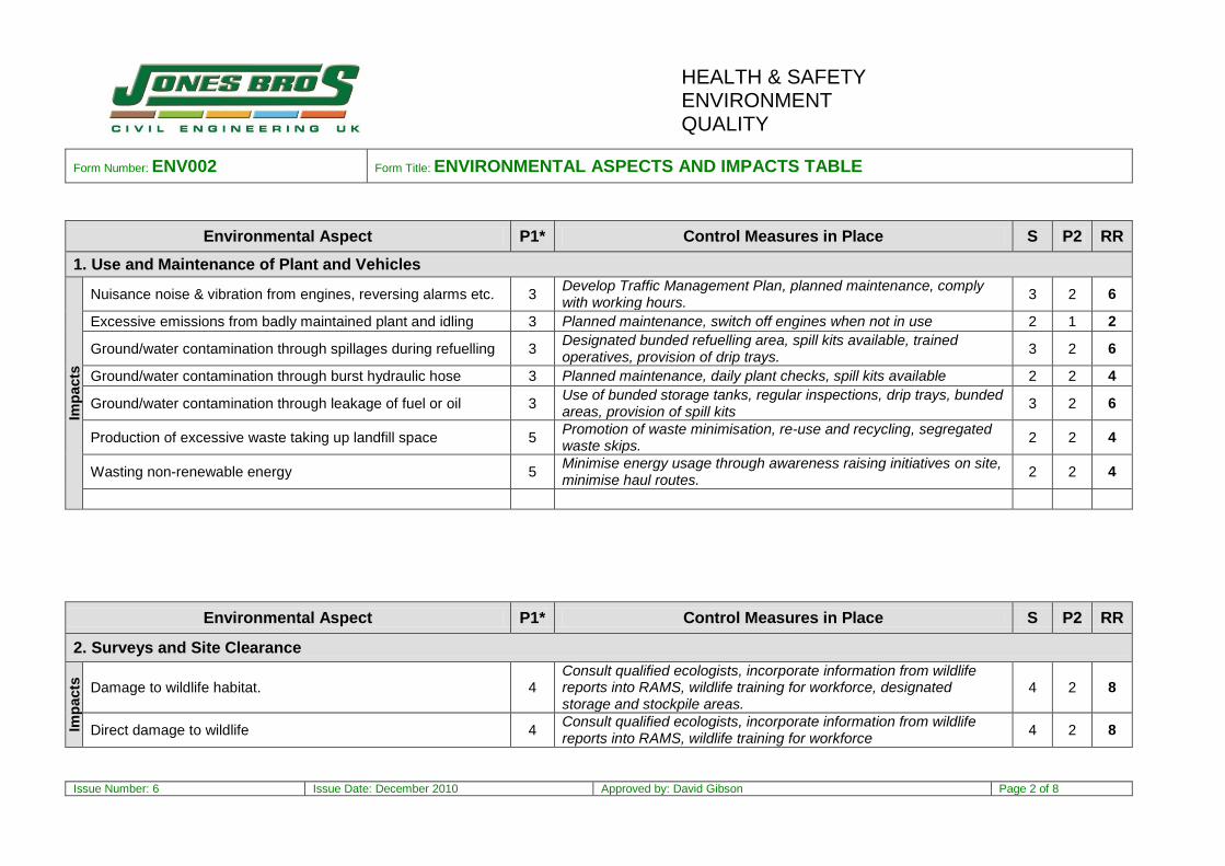
P1* = The Probability of the Impact affecting the environmental receptor without control measures in place P2 = The Probability of the Impact affecting the environmental receptor once control measures are in place
REVIEW: This document shall be reviewed as often as is required to ensure that it accurately reflects the hazards, risks and control measures of the project. Its accuracy is confirmed monthly on the Attestation Form (GEN009), by the Contracts Manager.
Date Reviewed
Name of Reviewer Nature of Changes Signed
CONTRACT NAME CONTRACT
NUMBER SITE START
DATE SITE MANAGER CONTRACTS MANAGER
Strathy Wood Wind Farm TBA TBA Alan Manuel Mike O’Connor
Severity (S) Probability (P) Risk Rating (RR)
0 = No environmental impact 0 = Highly unlikely 0 - Insignificant
1 = Very minor impact 1 = Very unlikely 1 – 3 - Low
2 = Minor impact 2 = Unlikely 4 – 10 - Medium
3 = Significant impact 3 = Likely Above 10 - High
4 = Major impact 4 = Very likely
5 = Global impact 5 = Almost certain Calculation SxP2=RR
HEALTH & SAFETY ENVIRONMENT QUALITY
Form Number: ENV002 Form Title: ENVIRONMENTAL ASPECTS AND IMPACTS TABLE
Issue Number: 6 Issue Date: December 2010 Approved by: David Gibson Page 2 of 8
Environmental Aspect P1* Control Measures in Place S P2 RR
1. Use and Maintenance of Plant and Vehicles
Imp
acts
Nuisance noise & vibration from engines, reversing alarms etc. 3 Develop Traffic Management Plan, planned maintenance, comply with working hours.
3 2 6
Excessive emissions from badly maintained plant and idling 3 Planned maintenance, switch off engines when not in use 2 1 2
Ground/water contamination through spillages during refuelling 3 Designated bunded refuelling area, spill kits available, trained operatives, provision of drip trays.
3 2 6
Ground/water contamination through burst hydraulic hose 3 Planned maintenance, daily plant checks, spill kits available 2 2 4
Ground/water contamination through leakage of fuel or oil 3 Use of bunded storage tanks, regular inspections, drip trays, bunded areas, provision of spill kits
3 2 6
Production of excessive waste taking up landfill space 5 Promotion of waste minimisation, re-use and recycling, segregated waste skips.
2 2 4
Wasting non-renewable energy 5 Minimise energy usage through awareness raising initiatives on site, minimise haul routes.
2 2 4
Environmental Aspect P1* Control Measures in Place S P2 RR
2. Surveys and Site Clearance
Imp
acts
Damage to wildlife habitat. 4 Consult qualified ecologists, incorporate information from wildlife reports into RAMS, wildlife training for workforce, designated storage and stockpile areas.
4 2 8
Direct damage to wildlife 4 Consult qualified ecologists, incorporate information from wildlife reports into RAMS, wildlife training for workforce
4 2 8

HEALTH & SAFETY ENVIRONMENT QUALITY
Form Number: ENV002 Form Title: ENVIRONMENTAL ASPECTS AND IMPACTS TABLE
Issue Number: 6 Issue Date: December 2010 Approved by: David Gibson Page 3 of 8
Environmental Aspect P1* Control Measures in Place S P2 RR
Damage to designated qualifying habitat 4 Consult qualified ecologists, agree measures with SNH, physical barriers site awareness , designated storage and stockpile areas, incorporate information into RAMS.
4 2 8
Spread of invasive species 3 Consult qualified ecologists, incorporate information from wildlife reports into RAMS, wildlife training for workforce
3 2 6
Nuisance dust, noise and/or vibration to people and wildlife 4 Damping down dust, comply with working hours, use of noise reduced plant and equipment, maintain haul roads, comply with speed limits
3 2 6
Production of excessive waste taking up landfill space 5 Promotion of waste minimisation, re-use and recycling, felled trees to be collected by Forestry commission.
2 2 4
Environmental Aspect P1* Control Measures in Place S P2 RR
3. Earthworks
Imp
acts
Damage to designated qualifying habitat 4 Define designated areas, agree measures with SNH, physical barriers site awareness , manage operations, designated storage and stockpile areas, incorporate information into RAMS.
4 2 8
Water pollution due to silt run-off during rainfall 4
Minimise area of disturbed land, create water settlement/storage areas, divert clean water round site, seal stockpiles to prevent sediment transportation, plan work around rainfall forecast, provide silt fencing, watercourse monitoring
4 2 8
Water pollution due to pumping silt contaminated water 4 Create water settlement/storage areas, install silt fencing, watercourse monitoring
4 2 8
Damaging topsoil through poor handling and storage 3 Minimise handling, manage stockpiles, minimise activity durations, incorporate good practice into RAMS, training for workforce
2 2 4
Mixing topsoil and subsoil 3 Manage operations, Discrete Stockpiling to be undertaken, Incorporate good practice into RAMS, training for workforce
2 2 4
Nuisance dust 4 Damping down dust, maintain haul roads, comply with speed limits. 3 2 6
HEALTH & SAFETY ENVIRONMENT QUALITY
Form Number: ENV002 Form Title: ENVIRONMENTAL ASPECTS AND IMPACTS TABLE
Issue Number: 6 Issue Date: December 2010 Approved by: David Gibson Page 4 of 8
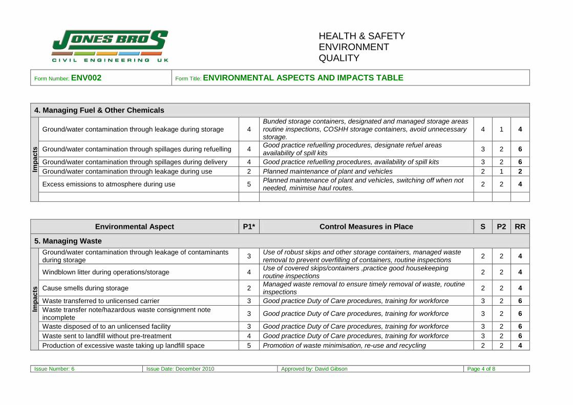
4. Managing Fuel & Other Chemicals
Imp
acts
Ground/water contamination through leakage during storage 4 Bunded storage containers, designated and managed storage areas routine inspections, COSHH storage containers, avoid unnecessary storage.
4 1 4
Ground/water contamination through spillages during refuelling 4 Good practice refuelling procedures, designate refuel areas availability of spill kits
3 2 6
Ground/water contamination through spillages during delivery 4 Good practice refuelling procedures, availability of spill kits 3 2 6
Ground/water contamination through leakage during use 2 Planned maintenance of plant and vehicles 2 1 2
Excess emissions to atmosphere during use 5 Planned maintenance of plant and vehicles, switching off when not needed, minimise haul routes.
2 2 4
Environmental Aspect P1* Control Measures in Place S P2 RR
5. Managing Waste
Imp
acts
Ground/water contamination through leakage of contaminants during storage
3 Use of robust skips and other storage containers, managed waste removal to prevent overfilling of containers, routine inspections
2 2 4
Windblown litter during operations/storage 4 Use of covered skips/containers ,practice good housekeeping routine inspections
2 2 4
Cause smells during storage 2 Managed waste removal to ensure timely removal of waste, routine inspections
2 2 4
Waste transferred to unlicensed carrier 3 Good practice Duty of Care procedures, training for workforce 3 2 6
Waste transfer note/hazardous waste consignment note incomplete
3 Good practice Duty of Care procedures, training for workforce 3 2 6
Waste disposed of to an unlicensed facility 3 Good practice Duty of Care procedures, training for workforce 3 2 6
Waste sent to landfill without pre-treatment 4 Good practice Duty of Care procedures, training for workforce 3 2 6
Production of excessive waste taking up landfill space 5 Promotion of waste minimisation, re-use and recycling 2 2 4
HEALTH & SAFETY ENVIRONMENT QUALITY
Form Number: ENV002 Form Title: ENVIRONMENTAL ASPECTS AND IMPACTS TABLE
Issue Number: 6 Issue Date: December 2010 Approved by: David Gibson Page 5 of 8
Environmental Aspect P1* Control Measures in Place S P2 RR
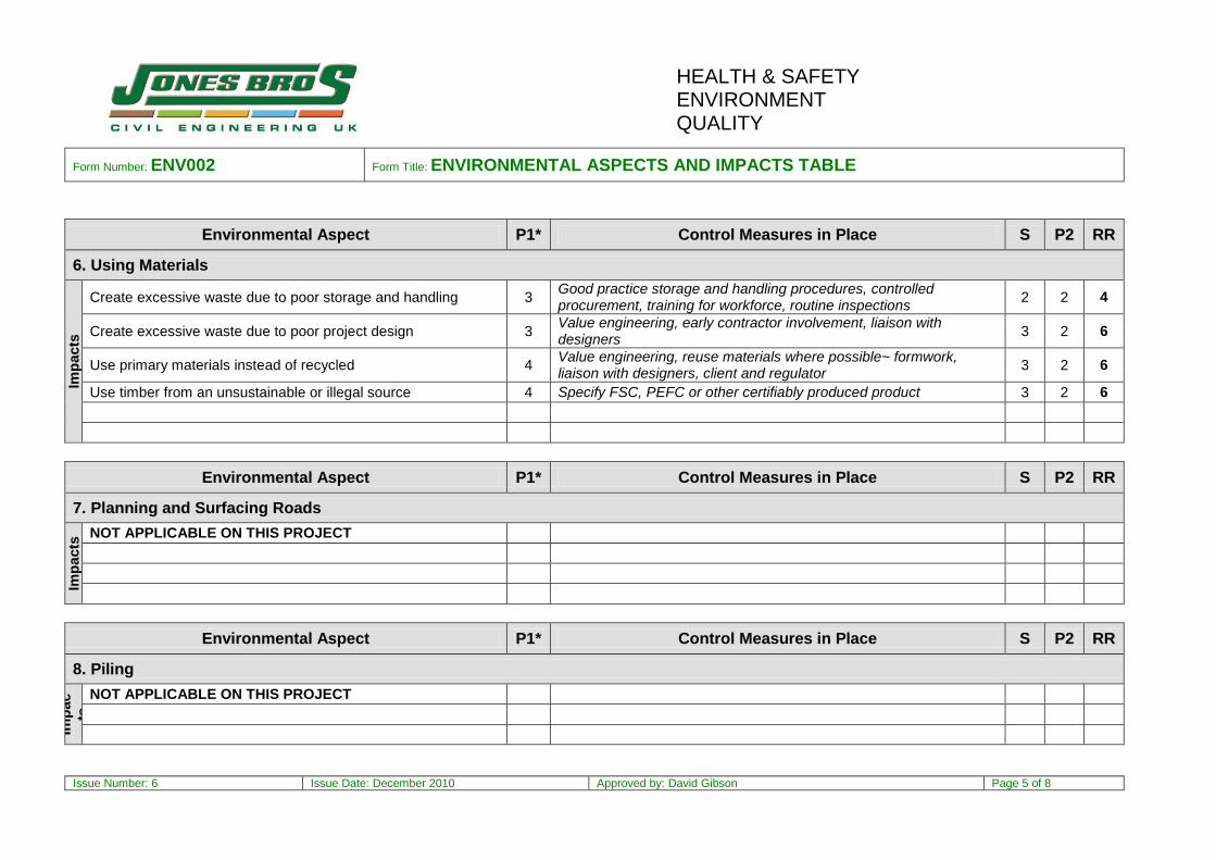
6. Using Materials
Imp
acts
Create excessive waste due to poor storage and handling 3 Good practice storage and handling procedures, controlled procurement, training for workforce, routine inspections
2 2 4
Create excessive waste due to poor project design 3 Value engineering, early contractor involvement, liaison with designers
3 2 6
Use primary materials instead of recycled 4 Value engineering, reuse materials where possible~ formwork, liaison with designers, client and regulator
3 2 6
Use timber from an unsustainable or illegal source 4 Specify FSC, PEFC or other certifiably produced product 3 2 6
Environmental Aspect P1* Control Measures in Place S P2 RR
7. Planning and Surfacing Roads
Imp
acts
NOT APPLICABLE ON THIS PROJECT
Environmental Aspect P1* Control Measures in Place S P2 RR
8. Piling
Imp
ac
ts
NOT APPLICABLE ON THIS PROJECT
HEALTH & SAFETY ENVIRONMENT QUALITY
Form Number: ENV002 Form Title: ENVIRONMENTAL ASPECTS AND IMPACTS TABLE
Issue Number: 6 Issue Date: December 2010 Approved by: David Gibson Page 6 of 8
Environmental Aspect P1* Control Measures in Place S P2 RR
Environmental Aspect P1* Control Measures in Place S P2 RR
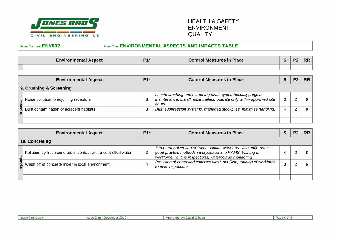
9. Crushing & Screening
Imp
acts
Noise pollution to adjoining receptors 3 Locate crushing and screening plant sympathetically, regular maintenance, install noise baffles, operate only within approved site hours.
3 2 6
Dust contamination of adjacent habitats 3 Dust suppression systems, managed stockpiles, minimise handling. 4 2 8
Environmental Aspect P1* Control Measures in Place S P2 RR
10. Concreting
Imp
acts
Pollution by fresh concrete in contact with a controlled water 3 Temporary diversion of River , isolate work area with cofferdams, good practice methods incorporated into RAMS, training of workforce, routine inspections, watercourse monitoring
4 2 8
Wash off of concrete mixer in local environment 4 Provision of controlled concrete wash out Skip, training of workforce, routine inspections
3 2 6
HEALTH & SAFETY ENVIRONMENT QUALITY
Form Number: ENV002 Form Title: ENVIRONMENTAL ASPECTS AND IMPACTS TABLE
Issue Number: 6 Issue Date: December 2010 Approved by: David Gibson Page 7 of 8
Environmental Aspect P1* Control Measures in Place S P2 RR
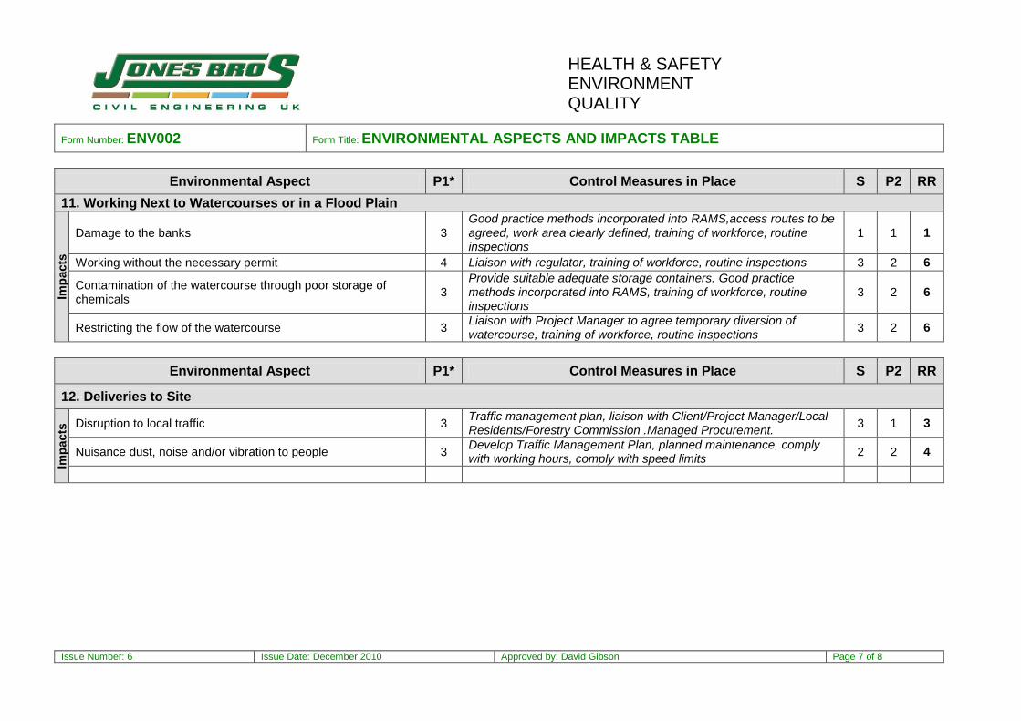
11. Working Next to Watercourses or in a Flood Plain
Imp
acts
Damage to the banks 3 Good practice methods incorporated into RAMS,access routes to be agreed, work area clearly defined, training of workforce, routine inspections
1 1 1
Working without the necessary permit 4 Liaison with regulator, training of workforce, routine inspections 3 2 6
Contamination of the watercourse through poor storage of chemicals
3 Provide suitable adequate storage containers. Good practice methods incorporated into RAMS, training of workforce, routine inspections
3 2 6
Restricting the flow of the watercourse 3 Liaison with Project Manager to agree temporary diversion of watercourse, training of workforce, routine inspections
3 2 6
Environmental Aspect P1* Control Measures in Place S P2 RR
12. Deliveries to Site
Imp
acts
Disruption to local traffic 3 Traffic management plan, liaison with Client/Project Manager/Local Residents/Forestry Commission .Managed Procurement.
3 1 3
Nuisance dust, noise and/or vibration to people 3 Develop Traffic Management Plan, planned maintenance, comply with working hours, comply with speed limits
2 2 4
HEALTH & SAFETY ENVIRONMENT QUALITY
Form Number: ENV002 Form Title: ENVIRONMENTAL ASPECTS AND IMPACTS TABLE
Issue Number: 6 Issue Date: December 2010 Approved by: David Gibson Page 8 of 8
Environmental Aspect P1* Control Measures in Place S P2 RR
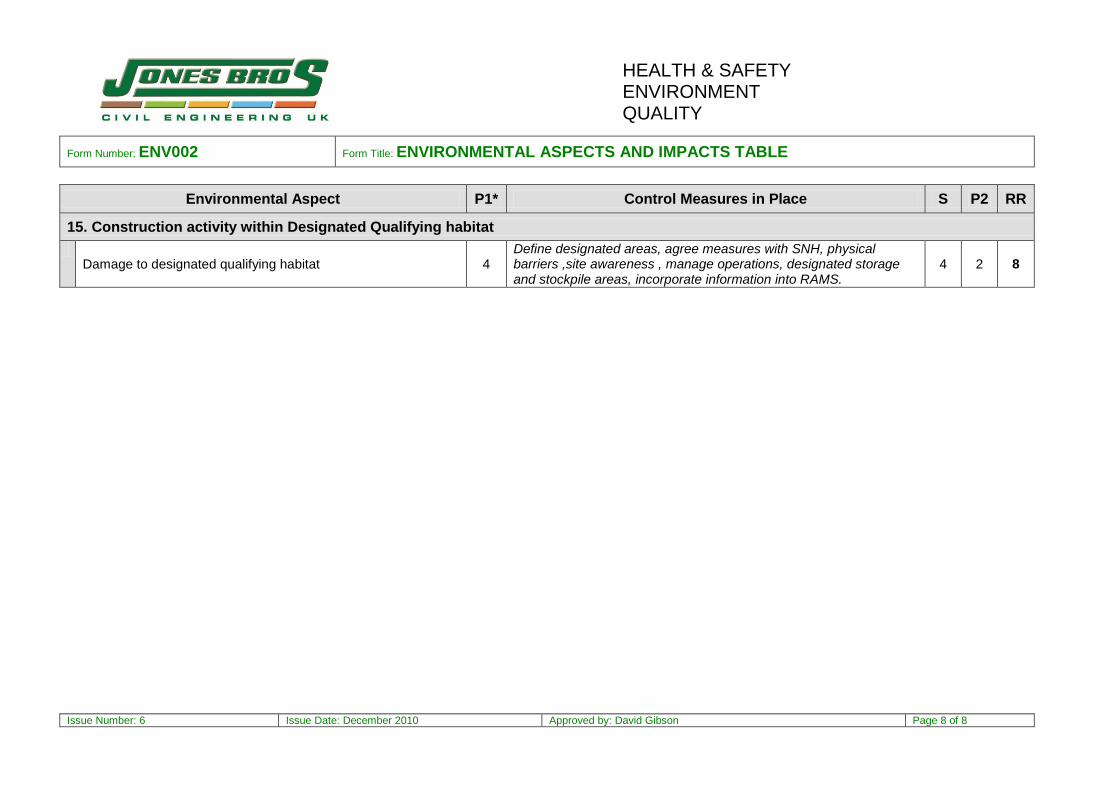
15. Construction activity within Designated Qualifying habitat
Damage to designated qualifying habitat 4
Define designated areas, agree measures with SNH, physical barriers ,site awareness , manage operations, designated storage and stockpile areas, incorporate information into RAMS.
4 2 8

Strathy Wood ~ WTG 14,18,22 & 23
Programme Title: Notes: Programme no: Revision:
Drawn By: Date Drawn: Revision Date: 28th October 2013
03
October 2013Mike O'Connor
MOC/001
Conceptual Programme
ID1
2
3
4
5
6
7
8
9
10
11
12
13
14
15
16
17
18
19
20
21
22
23
24
25
26
27
28
29
30
31
32
33
34
35
36
37
38
39
40
41
42
43
44
45
46
47
48
49
50
51
52
53
54
55
56
57
58
59
60
61
62
63
64
65
66
67
68
Name Southern access Track Construction
Access Track and hardstanding Construction
Temporary Access Track~ To By Pass WTG 14
Temporary Access Track~ To by Pass WTG 18
Wind Turbine Generator Foundation 14 Construction
Setting Out & define qualifying area boundary
Vegtation Strip within defined area
Excavation to formation inc 1 in 1 cut slopes
Installation of Cable Ducts
Blinding to base
Fabricate Bolt Set
Fabricate cage to Kicker Level
Pour Base Concrete
Shutter to upstand
Pour Upstand
Strip shutters and structural backfill
Reinstate working area
WTG Component delivery
WTG Erection
Temporary Laydown ,establish and removal
Wind Turbine Generator Foundation 18 Construction
Setting Out & define qualifying area boundary
Vegtation Strip within defined area
Excavation to formation inc 1 in 1 cut slopes
Installation of Cable Ducts
Blinding to base
Fabricate Bolt Set
Fabricate cage to Kicker Level
Pour Base Concrete
Shutter to upstand
Pour Upstand
Strip shutters and structural backfill
Reinstate working area
WTG Component delivery
WTG Erection
Temporary Laydown ,establish and removal
Wind Turbine Generator Foundation 22 Construction
Setting Out & define qualifying area boundary
Vegtation Strip within defined area
Excavation to formation inc 1 in 1 cut slopes
Installation of Cable Ducts
Blinding to base
Fabricate Bolt Set
Fabricate cage to Kicker Level
Pour Base Concrete
Shutter to upstand
Pour Upstand
Strip shutters and structural backfill
Reinstate working area
WTG Component delivery
WTG Erection
Temporary Laydown ,establish and removal
Wind Turbine Generator Foundation 23 Construction
Setting Out & define qualifying area boundary
Vegtation Strip within defined area
Excavation to formation inc 1 in 1 cut slopes
Installation of Cable Ducts
Blinding to base
Fabricate Bolt Set
Fabricate cage to Kicker Level
Pour Base Concrete
Shutter to upstand
Pour Upstand
Strip shutters and structural backfill
Reinstate working area
WTG Component delivery
WTG Erection
Temporary Laydown ,establish and removal
Dur75d
50d
58d
63d
62d
2d
1d
3d
2d
1d
2d
7d
1d
1d
1d
3d
4d
5d
5d
12d
61d
2d
1d
3d
2d
1d
2d
7d
1d
1d
1d
3d
4d
5d
5d
12d
49d
2d
2d
3d
2d
1d
2d
7d
1d
1d
1d
3d
4d
5d
5d
12d
60d
2d
1d
3d
2d
1d
2d
7d
1d
1d
1d
3d
4d
5d
5d
12d
Start03 Mar 14
03 Mar 14
05 Mar 14
19 Mar 14
03 Mar 14
03 Mar 14
05 Mar 14
06 Mar 14
11 Mar 14
13 Mar 14
17 Mar 14
19 Mar 14
28 Mar 14
02 Apr 14
03 Apr 14
07 Apr 14
10 Apr 14
12 May 14
19 May 14
12 May 14
18 Mar 14
18 Mar 14
20 Mar 14
21 Mar 14
26 Mar 14
28 Mar 14
31 Mar 14
02 Apr 14
11 Apr 14
16 Apr 14
17 Apr 14
22 Apr 14
25 Apr 14
26 May 14
02 Jun 14
26 May 14
05 Jun 14
05 Jun 14
09 Jun 14
11 Jun 14
16 Jun 14
18 Jun 14
19 Jun 14
23 Jun 14
02 Jul 14
07 Jul 14
08 Jul 14
09 Jul 14
14 Jul 14
28 Jul 14
04 Aug 14
28 Jul 14
07 May 14
07 May 14
09 May 14
12 May 14
15 May 14
19 May 14
20 May 14
22 May 14
02 Jun 14
05 Jun 14
06 Jun 14
11 Jun 14
16 Jun 14
14 Jul 14
21 Jul 14
14 Jul 14
Finish13 Jun 14
09 May 14
23 May 14
13 Jun 14
27 May 14
04 Mar 14
05 Mar 14
10 Mar 14
12 Mar 14
13 Mar 14
18 Mar 14
27 Mar 14
28 Mar 14
02 Apr 14
03 Apr 14
09 Apr 14
15 Apr 14
16 May 14
23 May 14
27 May 14
10 Jun 14
19 Mar 14
20 Mar 14
25 Mar 14
27 Mar 14
28 Mar 14
01 Apr 14
10 Apr 14
11 Apr 14
16 Apr 14
17 Apr 14
24 Apr 14
30 Apr 14
30 May 14
06 Jun 14
10 Jun 14
12 Aug 14
06 Jun 14
10 Jun 14
13 Jun 14
17 Jun 14
18 Jun 14
20 Jun 14
01 Jul 14
02 Jul 14
07 Jul 14
08 Jul 14
11 Jul 14
17 Jul 14
01 Aug 14
08 Aug 14
12 Aug 14
29 Jul 14
08 May 14
09 May 14
14 May 14
16 May 14
19 May 14
21 May 14
30 May 14
02 Jun 14
05 Jun 14
06 Jun 14
13 Jun 14
19 Jun 14
18 Jul 14
25 Jul 14
29 Jul 14
March 2014 April 2014 May 2014 June 2014 July 2014 August 2014 September 201403 10 17 24 31 07 14 21 28 05 12 19 26 02 09 16 23 30 07 14 21 28 04 11 18 25 01
w1 w2 w3 w4 w5 w6 w7 w8 w9 w10 w11 w12 w13 w14 w15 w16 w17 w18 w19 w20 w21 w22 w23 w24 w25 w26 w27
Southern access Track Construction
Access Track and hardstanding Construction
Temporary Access Track~ To By Pass WTG 14
Temporary Access Track~ To by Pass WTG 18
Wind Turbine Generator Foundation 14 Construction
Setting Out & define qualifying area boundary
Vegtation Strip within defined area
Excavation to formation inc 1 in 1 cut slopes
Installation of Cable Ducts
Blinding to base
Fabricate Bolt Set
Fabricate cage to Kicker Level
Pour Base Concrete
Shutter to upstand
Pour Upstand
Strip shutters and structural backfill
Reinstate working area
WTG Component delivery
WTG Erection
Temporary Laydown ,establish and removal
Wind Turbine Generator Foundation 18 Construction
Setting Out & define qualifying area boundary
Vegtation Strip within defined area
Excavation to formation inc 1 in 1 cut slopes
Installation of Cable Ducts
Blinding to base
Fabricate Bolt Set
Fabricate cage to Kicker Level
Pour Base Concrete
Shutter to upstand
Pour Upstand
Strip shutters and structural backfill
Reinstate working area
WTG Component delivery
WTG Erection
Temporary Laydown ,establish and removal
Wind Turbine Generator Foundation 22 Construction
Setting Out & define qualifying area boundary
Vegtation Strip within defined area
Excavation to formation inc 1 in 1 cut slopes
Installation of Cable Ducts
Blinding to base
Fabricate Bolt Set
Fabricate cage to Kicker Level
Pour Base Concrete
Shutter to upstand
Pour Upstand
Strip shutters and structural backfill
Reinstate working area
WTG Component delivery
WTG Erection
Temporary Laydown ,establish and removal
Wind Turbine Generator Foundation 23 Construction
Setting Out & define qualifying area boundary
Vegtation Strip within defined area
Excavation to formation inc 1 in 1 cut slopes
Installation of Cable Ducts
Blinding to base
Fabricate Bolt Set
Fabricate cage to Kicker Level
Pour Base Concrete
Shutter to upstand
Pour Upstand
Strip shutters and structural backfill
Reinstate working area
WTG Component delivery
WTG Erection
Temporary Laydown ,establish and removal

Strathy Wood Wind Farm
Construction Method Statement

Construction Method Statement
Contents 1.0 Introduction & Scope 2.0 Access and Mobilisation 3.0 Environmental Management 4.0 Traffic Management 5.0 Borrow Pits 6.0 Access Tracks 7.0 Construction ~ Northern Access Track 8.0 Construction ~ Southern Access Track 9.0 Proposed Turning Area CH 2440 10.0 Proposed Temporary Bypasses 11.0 Wind Turbine Generator Foundations Appendices 1 Example Environmental Risk Assessment 2 Conceptual Construction Programme

1.0 Introduction & Scope
1.1 The proposed Strathy Wood Windfarm development is located in an area formally used as forestry and is accessed via an existing access track travelling North to South from Strathy Wood North to Strathy Wood South. The landscape to each side of this existing access track has been designated as an SAC, Special Area of Conservation.
1.2 This Construction Method Statement addresses the methodology required
to construct the elements of the Project that are adjoining the SAC, in particular the improvement of access tracks, provision of watercourse crossings and construction of turbine bases with associated hard stands . Specifically the Northern access track, Southern access track and Turbine„s 14, 18, 22 and 23.
1.3 The following principles will be adopted:
Undertake construction activities within areas of non-qualifying habitat.
Minimise encroachment and subsequent loss of qualifying habitat.
Maximise opportunity to re-establish area‟s that would re-generate into areas of qualifying habitat.
2.0 Access and Mobilisation
2.1 The proposed development site is situated approximately 8.5km south of the village of Strathy and the A836 trunk road, Sutherland. All access to the site is via the A836, thereafter access is shared with isolated local properties and access to the Strathy North wind farm development. 2.2 Strathy North is currently under construction and the access track between the A836 and that Site entrance has already been improved. 2.3 The remainder of the track is passable but continued heavy usage is not desirable until the required improvements have been undertaken. 2.4 It is anticipated that access to the proposed Contractors compound area, indicated on Figure 1-2 Site Layout, of Vol 3 of the ES. will be facilitated via the existing access track. Thereafter improvements will be undertaken using materials won from the on site borrow pit indicated on the above referenced drawing.
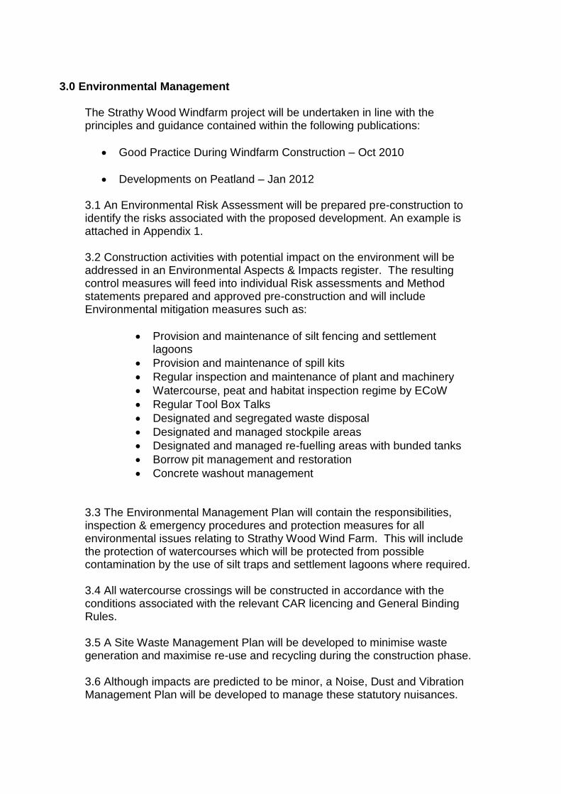
3.0 Environmental Management
The Strathy Wood Windfarm project will be undertaken in line with the principles and guidance contained within the following publications:
Good Practice During Windfarm Construction – Oct 2010
Developments on Peatland – Jan 2012 3.1 An Environmental Risk Assessment will be prepared pre-construction to identify the risks associated with the proposed development. An example is attached in Appendix 1.
3.2 Construction activities with potential impact on the environment will be addressed in an Environmental Aspects & Impacts register. The resulting control measures will feed into individual Risk assessments and Method statements prepared and approved pre-construction and will include Environmental mitigation measures such as:
Provision and maintenance of silt fencing and settlement lagoons
Provision and maintenance of spill kits
Regular inspection and maintenance of plant and machinery
Watercourse, peat and habitat inspection regime by ECoW
Regular Tool Box Talks
Designated and segregated waste disposal
Designated and managed stockpile areas
Designated and managed re-fuelling areas with bunded tanks
Borrow pit management and restoration
Concrete washout management 3.3 The Environmental Management Plan will contain the responsibilities, inspection & emergency procedures and protection measures for all environmental issues relating to Strathy Wood Wind Farm. This will include the protection of watercourses which will be protected from possible contamination by the use of silt traps and settlement lagoons where required. 3.4 All watercourse crossings will be constructed in accordance with the conditions associated with the relevant CAR licencing and General Binding Rules. 3.5 A Site Waste Management Plan will be developed to minimise waste generation and maximise re-use and recycling during the construction phase. 3.6 Although impacts are predicted to be minor, a Noise, Dust and Vibration Management Plan will be developed to manage these statutory nuisances.

The local Environmental Health Officer will be consulted on the proposed control measures and their suggestions will be incorporated into the plan. 3.7 Due to the complex and comprehensive ecological issues this project contains, an Environmental Management Plan will be developed with the relevant consultants to outline how the various habitats and species will be protected and where possible, enhanced. This will include:
Lines of communication;
Responsibilities;
All mitigation measures;
Monitoring regime;
Links to other Plans within the Environmental Management Plan, including the Peat Management Plan.
3.8 A detailed Peat Management Plan, building on Appendix 11.7 of the ES, describing the resource and measures taken to minimise the impact on it, will be developed during the course of the preconstruction stage. 3.9 A strict method of refuelling will be implemented which will prevent any possible diesel fuel/oils escaping and again possibly contaminating the site. This will include designated fuelling areas. A Pollution Control Plan will be developed during the construction phase of the works which will contain procedures for dealing with emergencies. The plan will be submitted to SEPA for approval, be communicated to the workforce by Toolbox talk and be displayed in the Site Offices and adjacent to fuel bowsers and watercourses. The information contained within the Pollution Control Plan shall include the following,
Site layout Plan.
Emergency Contact List including spill management company .
List of polluting materials
Control Measures
Procedures in the event of an incident.
Incident Report Forms.
COSHH Inventory.
Spill Kit Inventory.
Toolbox talk and training register.
4.0 Traffic Management
4.1 A Traffic Management Plan will be developed pre-construction to ensure that all planned traffic movements can be accommodated throughout the construction phase of the Project. Proposed delivery schedules will be

accommodated within the TMP to ensure safe access is available and the Construction programme is not disrupted.
4.2 Opportunities exist to provide passing places for construction traffic within the non-qualifying habitat areas beside the existing track. Potential opportunities can be identified pre-construction, as indicated on Figures 4-24, 4-25 and 4-9 respectively. Final verification will be undertaken on site with regard suitability of levels. No- qualifying areas that may provide passing place opportunity are located at the following chainages on the Northern access track: CH 110.0, 250.0, 500.0, 800.0, 980.0, 1380.0, 1550.0, 1720.0, 1860.0, 1950.0, 2160.0, 2270.0 , 2500.0 and 2800.0. On the Southern access track opportunity exists at CH 490.0, 620.0, 1000.0, 1400.0, 1600.0 and 2080.0 . 4.3 These passing places will be clearly defined and signed with physical barriers established pre-construction to define the adjacent designated qualifying habitat areas. 4.4 Temporary access tracks will be established to facilitate access during permanent work activities, on the Northern access track at watercourse crossings requiring replacement bridges and on the Southern access track when WTG 14 and WTG 18 are constructed.
4.5 Access tracks will have a strict speed limit enforced during the construction phase to minimise dust migration from materials used in the access track construction into adjacent designated qualifying habitat areas. 4.6 The TMP will incorporate both construction and delivery phases of the Project to ensure efficient utilisation of the passing places constructed. 4.7 The TMP will be issued to suppliers in advance of attendance to site, briefed to site personnel during the site induction and displayed in the site welfare units.
5.0 Borrow Pits 5.1 A number of potential sources of rock have been identified within the proposed Project area during initial site inspections. The development of these borrow pits will be undertaken in accordance with the guidelines described in the Contract documentation. 5.2 Once identified on site the area to be developed will have the existing overburden of soils/peat and vegetation removed by excavator and carefully stockpiled in horizons for re-use as restoration material. 5.3 The drilling and blasting element of the Project will be undertaken by a competent specialist contractor. A site specific blast proposal will be developed which will detail the drill patterns, drill depths and number of holes to be drilled at each location.
This blast proposal will take into consideration the anticipated fracture pattern, blast radius and the end product required. 5.4 A blasting Risk Assessment and Method Statement will be prepared and submitted together with a specific Risk Assessment and Method statement that will be developed with the appointed specialist contractor prior to any blast taking place. 5.5 Upon completion a restoration plan for the borrow pits shall be developed and agreed with SEPA and SNH. Previously stockpiled excavated materials will be used in the restoration in addition to the surplus arisings from the borrow pit operation. Peat shall be systematically placed in the same horizon sequence of the excavation with the peat turves containing the seed bank being placed uppermost.
6.0 Access Tracks 6.1 The existing access track will require upgrading to comply with the minimum requirements specified by the wind turbine generator manufacturers. There are currently three suppliers under consideration,
Vestas V90 3Mw
Nordex N100 2.5 Mw
Siemens 101 3 Mw
Upgrading of the existing access track is dictated by the following criteria required for component deliveries;
a) Minimum width requirements and minimum turning radius,
both of which effect the horizontal alignment. b) Maximum gradients will dictate the vertical alignment. c) Minimum load bearing capacity which will dictate the strength
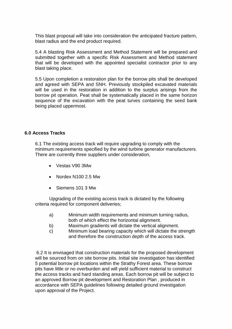
and therefore the construction depth of the access track. 6.2 It is envisaged that construction materials for the proposed development will be sourced from on site borrow pits. Initial site investigation has identified 5 potential borrow pit locations within the Strathy Forest area. These borrow pits have little or no overburden and will yield sufficient material to construct the access tracks and hard standing areas. Each borrow pit will be subject to an approved Borrow pit development and Restoration Plan , produced in accordance with SEPA guidelines following detailed ground investigation upon approval of the Project.
6.3 The construction sequence for the access tracks will be;
Set out and define the boundaries of qualifying and non-qualifying habitat.
Identify and set out areas of non –qualifying habitat that will provide space to construct passing places and turning areas.
Set out lengths of access track improvement.
Construct the passing bays.
Upgrade the access track.
6.4 A full topographical survey will be undertaken pre-commencement to confirm the proposed design. Horizontal and vertical alignment will be optimised to achieve minimum Specification requirements for the turbine manufacturers within the designated non-qualifying areas.
6.5 At present it is anticipated that the existing access track construction will be supplemented and widened using a geo-grid and 300mm depth of additional granular material. A typical construction detail is indicated on Figure 4-10.
6.6 Once the alignments are set out and agreed the boundary between the designated non-qualifying habitat and qualifying habitat will be physically defined and passing places identified.
6.7 In areas where construction materials will not migrate into the qualifying habitat,ie where access track construction is in cut, the boundary will be defined by posts and warning tape. Where there is a possibility of construction materials migrating into the qualifying habitat, ie access track construction in fill, then the boundary will be defined by a substantial “catch” fence, such as a chain link complete with silt netting on the construction side of the fence. The catch fence will be restrained and supplemented at the base by a small linear bund formed from the excavated arisings from the access track alterations. These fences will eliminate the possibility of construction materials rolling downhill and into the designated qualifying habitat. They will be regularly inspected and maintained.
6.8 All works will utilise the existing access track as a working platform and will not commence until the boundaries are established.
6.9 The access tracks covered by this report can be defined as two clear elements.
Firstly, the Northern access track i.e. through the SAC south of the Dallangwell turn off to Strathy North and the entrance to the main site. The new track section and improvement of the existing access track between the public road and the Dallangwell turn off is currently being constructed for access into Strathy North. This will be the main route into Strathy wood where the majority of the proposed turbines and the potential borrow pits are located. Progress along this section of access track will dictate access to the main site.
Secondly, the Southern access track, located outwith the commercial forest area ,transiting the SAC and terminating at Strathy South. This
section of track affords access only to four of the proposed turbine locations and consequently will not affect any other activities on site.
6.10 The protection of the qualifying habitat is extremely important and the control measures will be briefed to the workforce in a number of ways through induction, toolbox talks, daily briefings,risk assessments, method statements and information posters displayed in the all site accommodation units. Passing Places and Turning areas 6.10 During construction and operation of the proposed development, passing places and turning areas are required as the access track width will not facilitate the passing of two vehicles, early construction will ensure efficient traffic management which in turn will facilitate the commencement of activities at other locations on site. There is opportunity to provide sufficient areas for this purpose by utilising areas within the non qualifying habitat. 6.11 Where opportunity exists, we will create suitable habitat within areas of non qualifying habitat by translocating site-won vegetation. This will encourage the re-establishment of qualifying habitat and contribute to the off-setting of habitat loss. 6.12 Once a potential passing place is identified, the existing vegetation will be removed by excavator using a ditching bucket. This vegetation will be carefully stockpiled within the non designated area for later re-use. 6.13 The footprint of the passing place will be set out and granular material transported from the on -site borrow pits, deposited, spread and compacted. Subsoil will be placed between the passing place footprint and the boundary of the non qualifying area followed by the replacement of the previously excavated vegetation.

This site of former material extraction lies within the designated non-qualifying habitat on the Northern access road. It has potential uses , once existing vegetation is removed, as a turning area, passing bay, materials stockpile,( ie stripped peat turves for re-use ) or the location for a settlement lagoon.
7.0 Construction ~ Northern Access Track
7.1 It is proposed to upgrade the Northern access track utilising materials won from on site borrow pit identified near the compound area on Figure 1-2 Site Layout, of Vol 3 of the ES , this initial borrow pit will be developed immediately following mobilisation. Materials will be crushed and graded at the borrow pit location and transported by dumpers to the point of deposition. Anticipated operations are the widening of the existing track and strengthening of the existing construction. 7.2 Access track widening operations will progress from the compound area northwards to tie into the upgraded track at Dallangewell junction and be restricted to one side of the access track in order to provide potential local stockpile areas for removed turves on the opposite side of the track. 7.3 A 360 degree excavator with ditching bucket will progress from the start chainage, supervised by a banks man, removing vegetation and sub soils from within the designated non-qualifying habitat to expose a suitable formation layer.

7.4 Where turves exist, the peat turves will be excavated and stockpiled separately for re-use during the reinstatement. The removed turves will be stockpiled on raised mats, such as pallets placed on the existing vegetation within the opposite non-qualifying area in order to minimise handling and preserve the integrity of the turf. The turves will be placed vegetation uppermost, in a single layer. Construction will be programmed such that a section of access track is completed within the working day, this will allow the turves to be replaced and the storage pallets moved to the next section. This will ensure preservation of both the turf and the underlying vegetation. 7.5 Surplus and unsuitable arisings from this operation will be loaded into attending dumpers and transported to the designated stockpile areas. Subject to Planning approval the stockpile areas will be as per temporary stockpile areas identified on Figure 11.1, the surplus material will be incorporated in the borrow pit restoration.
7.6 Sufficient resource will be allocated to the operation to ensure efficient progress, attending dumpers removing surplus material to the borrow pit stockpiles will return with suitable material won from the borrow pit.
7.7 The transported granular material will be deposited and levelled by the excavator and compacted by self propelled smooth drum roller .The compacted material in turn trimmed to the required profile by the 360 degree excavator. Surplus material from the trimming operation will be loaded into attending dumpers for re-use.
7.8 Where the pre-commencement investigation has identified the need to strengthen the access track construction, the existing access road surface will be broken by the excavator and geogrid will be manually deployed. Granular material from the on site borrow pits will be placed and compacted by the excavator to the required construction depth. Trimming of the compacted material will take place as described above.
7.9 Once the trimmed profile is complete the previously removed turves will be re-placed, vegetation uppermost, to encourage re-generation and mitigate the run off of fines from the newly constructed access road. 7.10 Each section of access track improvement will be programmed such that the vegetation strip and excavation will not exceed the length of track that can be improved and reinstated within the working day. This will eliminate unnecessary and prolonged stockpiling and mitigate the effect of exposed granular construction materials.
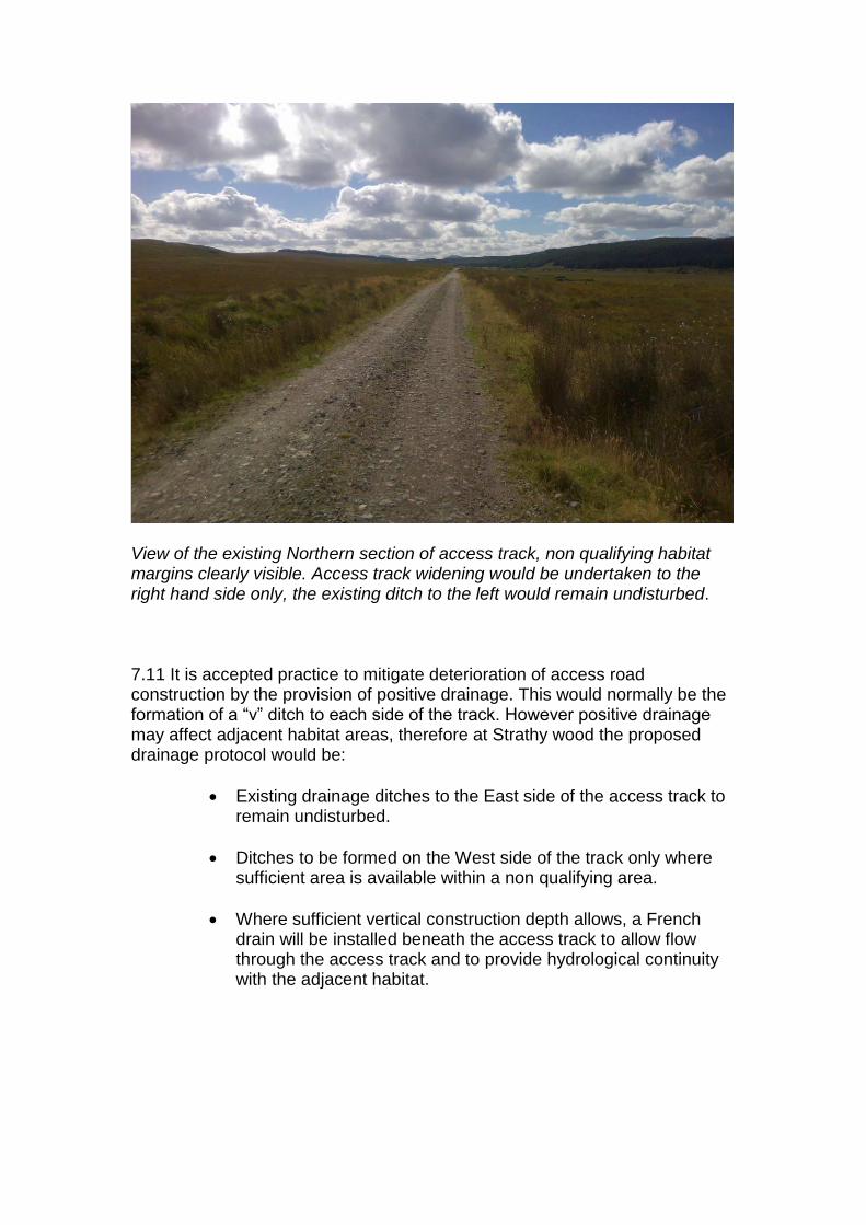
View of the existing Northern section of access track, non qualifying habitat margins clearly visible. Access track widening would be undertaken to the right hand side only, the existing ditch to the left would remain undisturbed. 7.11 It is accepted practice to mitigate deterioration of access road construction by the provision of positive drainage. This would normally be the formation of a “v” ditch to each side of the track. However positive drainage may affect adjacent habitat areas, therefore at Strathy wood the proposed drainage protocol would be:
Existing drainage ditches to the East side of the access track to remain undisturbed.
Ditches to be formed on the West side of the track only where sufficient area is available within a non qualifying area.
Where sufficient vertical construction depth allows, a French drain will be installed beneath the access track to allow flow through the access track and to provide hydrological continuity with the adjacent habitat.

7.12 A number of watercourses have been identified along the Northern access track that will require replacement bridging due to the width and load bearing specifications of the Wind Turbine manufacturers. 7.13 In order to avoid “in river” works to the existing structures it is proposed to construct load bearing abutments within the existing access track and place a modular steel structure over the existing structure. The vertical alignments on both approaches will be altered to suit. The replacement structure would over span the existing structure, avoiding demolition and potential in river works. A Schematic representation is shown on Figure 4-27. 7.14 Whilst the structure upgrading was ongoing access would need to be maintained. This would be facilitated by the provision of a second modular steel structure placed on temporary supports at each bank within the non-qualifying area. Access to the temporary structure would be via a temporary access track constructed as a floating construction ie a geotextile and geogrid is manually deployed onto the existing vegetation. Granular fill is transported from the borrow pits, deposited, spread and compacted. 7.15 The temporary arrangement will remain in place until the permanent abutments are cast and strong enough to bear the modular structure. The temporary structure is then removed along with the access track. The geotextile is removed to re-expose the vegetation below. A schematic representation of access track construction on the Northern access track is shown on figure 4-21.
8.0 Construction ~ Southern Access Track 8.1 Lengths of the Southern access track to be improved will be identified and clearly defined prior to the commencement of construction operations, as with the North the minimum track width, load bearing capacity and horizontal alignment will dictate the improvement areas.
8.2 In addition the proposed location of four Wind Turbine Generators adjacent to the access track requires access track construction to incorporate associated crane hardstand areas.
8.3 The width of the identified non-qualifying habitat area is significantly larger on the Southern access track from chainage 1000 Southward due to previous development of the land pre-designation.
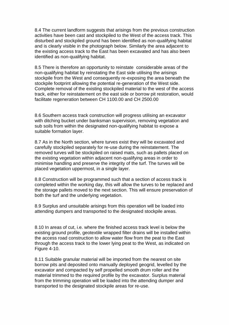
8.4 The current landform suggests that arisings from the previous construction activities have been cast and stockpiled to the West of the access track. This disturbed and stockpiled ground has been identified as non-qualifying habitat and is clearly visible in the photograph below. Similarly the area adjacent to the existing access track to the East has been excavated and has also been identified as non-qualifying habitat. 8.5 There is therefore an opportunity to reinstate considerable areas of the non-qualifying habitat by reinstating the East side utilising the arisings stockpile from the West and consequently re-exposing the area beneath the stockpile footprint allowing the potential re-generation of the West side. Complete removal of the existing stockpiled material to the west of the access track, either for reinstatement on the east side or borrow pit restoration, would facilitate regeneration between CH 1100.00 and CH 2500.00
8.6 Southern access track construction will progress utilising an excavator with ditching bucket under banksman supervision, removing vegetation and sub soils from within the designated non-qualifying habitat to expose a suitable formation layer.
8.7 As in the North section, where turves exist they will be excavated and carefully stockpiled separately for re-use during the reinstatement. The removed turves will be stockpiled on raised mats, such as pallets placed on the existing vegetation within adjacent non-qualifying areas in order to minimise handling and preserve the integrity of the turf. The turves will be placed vegetation uppermost, in a single layer.
8.8 Construction will be programmed such that a section of access track is completed within the working day, this will allow the turves to be replaced and the storage pallets moved to the next section. This will ensure preservation of both the turf and the underlying vegetation. 8.9 Surplus and unsuitable arisings from this operation will be loaded into attending dumpers and transported to the designated stockpile areas.
8.10 In areas of cut, i.e. where the finished access track level is below the existing ground profile, geotextile wrapped filter drains will be installed within the access road construction to allow water flow from the peat to the East through the access track to the lower lying peat to the West, as indicated on Figure 4-10.
8.11 Suitable granular material will be imported from the nearest on site borrow pits and deposited onto manually deployed geogrid, levelled by the excavator and compacted by self propelled smooth drum roller and the material trimmed to the required profile by the excavator. Surplus material from the trimming operation will be loaded into the attending dumper and transported to the designated stockpile areas for re-use.

8.12 A key part of the works will be the restoration of historical impacts along the access track. Once the access track for the wind farm has been improved the historic stockpiled material to the West of the track, dating from the original construction of the track a number of decades ago, will be removed and if deemed suitable, deposited in the non qualifying area to the East of the track. There is a drainage channel along the eastern side of the track. The aim is to infill the area of non-qualifying habitat to restore both sides of the track to qualifying habitat. To allow cross track drainage new geotextile wrapped filter drains will be installed within the access road construction. Particular care will be taken to remove the historic stockpiled material along the original vegetation line to facilitate appropriate revegetation from any viable seed bank that may remain.
8.13 Once the trimmed profile is complete, previously recovered turves will be placed, vegetation uppermost, to encourage re-generation and mitigate increases in run off.
View of the Southern access track at Ch 1950, looking North. The mound of deposited ground to the West is thought to have been generated from the original access track construction and is identified as non qualifying. The majority of this material can be relocated to the East of the access track into the non qualifying area in order to encourage regeneration.

A schematic representation of access track construction on the Southern access track is shown on Figure 4-22.
9.0 Proposed Turning Area CH 2440 9.1 Access track construction will continue beyond the proposed location of Wind Turbine generator No 23 in order to construct a turning area and temporary component parking area within an area identified as non-qualifying. Large articulated vehicles will need a turning area having delivered components. 9.2 Setting out will be undertaken as defined by the Specification, vegetation and turves where present will be stockpiled locally within adjacent areas of non-qualifying habitat. 9.3 Any further materials generated as a result of exposing a suitable formation will be transported by attending dumper to the designated stockpile area. 9.4 Suitable granular fill will be transported from the on-site borrow pits, spread and compacted as previously described. If the construction requires, geogrid will be manually deployed and granular material placed and compacted prior to final trim of the track edge and replacement of the locally stockpiled vegetation.
10.0 Proposed Temporary bypasses. 10.1 During the construction of the foundations for WTG 14 and WTG 18,
access south will be restricted. There is the opportunity in both cases to facilitate access southwards and therefore allow the continuation of the access track upgrade with the construction of a temporary access tracks within the adjoining Strathy forest area. Areas identified as non qualifying area adjoin the undesignated commercial forest area in a number of locations, the provision of a temporary access track across these areas will allow construction traffic to transit South and undertake construction of WTG 23 and WTG 22, as shown on Figure 1-2 Site Layout.
10.2 Granular site won material would be placed on geogrid, spread and
compacted to the correct tie-in levels and utilised for the construction period of WTG 14 and WTG 18 only. Upon completion of the WTG bases the permanent access track would be established and the temporary access road would be removed from the non qualifying area.
10.3 The proposed durations of these activities and the provision of temporary access tracks are indicated on the conceptual construction Programme, attached in Appendix 2.
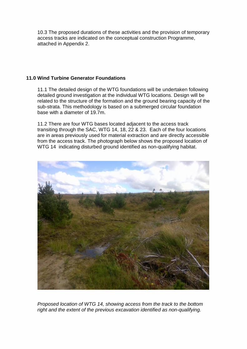
11.0 Wind Turbine Generator Foundations 11.1 The detailed design of the WTG foundations will be undertaken following detailed ground investigation at the individual WTG locations. Design will be related to the structure of the formation and the ground bearing capacity of the sub-strata. This methodology is based on a submerged circular foundation base with a diameter of 19.7m. 11.2 There are four WTG bases located adjacent to the access track transiting through the SAC, WTG 14, 18, 22 & 23. Each of the four locations are in areas previously used for material extraction and are directly accessible from the access track. The photograph below shows the proposed location of WTG 14 indicating disturbed ground identified as non-qualifying habitat.
Proposed location of WTG 14, showing access from the track to the bottom right and the extent of the previous excavation identified as non-qualifying.

11.3 Each WTG Base has a series of common activities and therefore the construction methodology can be applied to all four bases. The depth of excavation and working area footprint will vary depending on elevation in respect to existing ground levels and structural stability of the ground conditions encountered. In designing infrastructure on the non-qualifying corridor site specific topographic data has been used to better inform this initial design in three dimensions. Nevertheless, detailed ground investigation works will be required to inform detailed design work prior to construction. 11.4 The footprint of each WTG base together with typical sections indicating the effect on adjoining areas of qualifying habitat within the SAC is shown on the following drawings :
Turbine Ref Figure Ref OGL SAC GL Formation Level
WTG 14 4-13 & 4-17 136.00 140.00 133.00
WTG 18 4-14 & 4-18 152.00 154.00 149.00
WTG 22 4-15 & 4-19 149.50 151.00 146.50
WTG 23 4-16 & 4-20 162.00 165.00 159.00
11.5 The construction sequence is common to all four turbines and is defined as follows:
The definition, fencing off and signage of the qualifying habitat boundary.
The location of the foundation footprint and working area within the defined non-qualifying boundary.
The establishment of a retaining gabion basket structure if required.
The excavation to design formation.
The import and placement of graded structural fill from on site borrow pits.
The installation of cable ducts.
The placement of concrete blinding layer.
The fabrication of the turbine bolt set.
The fabrication of the reinforcement cage to the turbine foundation base.
The placement of structural concrete to the base.
The placement of the upstand shutter.
The placement of structural concrete to the upstand.
The installation of the earth mat.
Backfill of the base
Completion of the crane pads and hardstand including laydown areas.

A schematic representation of this sequence is indicated on figure 4-23 11.6 The Wind Turbine Generators are to be located in areas identified as non-qualifying habitat. However, adjacent areas are qualifying habitat and are higher ground. The boundary between the two habitats has already been defined by survey and is presented in the Ecology chapter. At the time of construction the boundary will be agreed with the on-site ECoW and defined prior to excavation commencing. 11.7 The footprint of the base, consisting of a 19.7m diameter structure together with a 2m working area around the foundation, will be set out in accordance with the detail design. The depth of excavation to formation level will be determined during the detailed design process. It will not be greater than 3 m below existing ground level. Therefore the initial design presented here is a realistic worst case scenario as the foundation excavation may not be as deep as 3m and hence actual areas of permanent direct and indirect effects may be less than predicted from this design work. Excavation side slopes will be established at a gradient of 1 in 1. Therefore the working footprint for a turbine foundation will be 370 m2 based on a diameter of 29.5m at top of plinth level. (The plinth is the central stub of the foundation that forms the highest point of the foundation and is where the bolt ring is located.) However, the actual land take required will vary from these conceptual distances which assume flat ground depending on the level differential with the adjoining land. The actual „cut line‟ for excavation will be determined by the level difference between the adjoining existing land and the design plinth level. 11.8 The foundation construction will be undertaken at a lower level than that of the surrounding peat area of qualifying habitat. Existing ground conditions must be assessed at this stage to determine the stability of the ground. If investigation confirms the ground is stable the area will be excavated at cut slopes of 1 in 1 in order to minimise the footprint and no further temporary works will be required. If the existing ground is not stable at 1in 1, to mitigate against peat slippage and consequential loss of qualifying habitat an allowance will be incorporated to allow the construction of a gabion basket retaining structure. 11.9 Access to the footprint will always be from the access track. Initially all vegetation will be removed from the identified footprint by excavator, material loaded and transported to designated stockpile areas adjacent to the on site borrow pits. Gabion Baskets 11.10 The use of a gabion basket retaining structure will only be employed if the existing ground cannot be self supporting when cut to a gradient of 1 in 1. The existing eastern face of the non-qualifying habitat area is to be excavated to a slope of 1 in 1 and a suitable founding level prepared with the excavator. Gabion baskets will be located at the toe of the cut 1 in 1 slope and manually

filled with suitable granular material won from the on site borrow pits. Once placed and filled the residual void behind will be filled with free granular material won from the borrow pits. 11.11As levels dictate, a second level of gabion baskets will be placed and filled on top of the first, as detailed by the structural Engineer. The hydrological integrity of the qualifying area at the interface between the peat and underlying strata will be retained by positioning an impermeable membrane behind the gabion baskets. Excavation 11.12 Excavation from existing ground level to design formation will be undertaken by excavator, utilising a hydraulic breaker as ground conditions dictate. The excavated material will be transported by attending dumpers to the designated stockpile areas adjacent to the borrow pits in Strathy Wood. The extended areas for crane pads and blade storage, constructed as part of the access track construction, will be utilised for work areas and vehicle turning during the excavation operation.
Excavation drainage 11.13 While excavation for the foundation is undertaken it will be necessary to provide drainage in order to manage water ingress to the excavation. For these four turbines it is particularly important to minimise and mitigate any adverse impact on drainage and additional land take to install drainage. To do this the following methods will be used to manage drainage of these four turbine excavations, during the period of the excavation:
No new cut-off drains on upslope side of excavations;
Establish shallow surface water ditches at the toe of the excavation, discharging via a settlement pond into existing non-qualifying habitat.
Establish settlement ponds within non-qualifying habitat (most likely within existing drain on east side of track) using silt management including straw bales and curtain traps.
Install a temporary impermeable membrane to retain water within the existing habitat.
Structural Fill 11.14 Once Formation level is achieved, tests will be undertaken to determine the bearing capacity of the ground. If proved suitable, the formation will be prepared with the self propelled roller. If the ground is not suitable or uneven, then processed structural fill will be transported from the on site borrow pits and placed and compacted in the foundation footprint. The fill will be proven by further testing.

Ducts 11.15 HDPE ducts must then be installed below the formation level along the agreed route. It is anticipated the cable route will be within the non qualifying margin adjacent to the access road and therefore the ducts will be installed from the track, eastward to the centre of the base. The duct trench will be excavated, arisings transported to stockpile by attending dumper and the trench sanded with suitable material brought back from the borrow pit on the return load. Ducts will be placed and surrounded in concrete. Concrete will be produced on site at the on site batching plant located within Strathy wood compound. Once batched, the concrete will be transported to WTG 14 by mixer and deposited into the trench from the access track. Concrete wagons will wash out in a designated washout skip located in a bunded area on the adjacent hardstand within the non- qualifying habitat. Wash out water will be removed from the skip for treatment.
Cabling 11.16 Cable runs will be required from each turbine back to the on-site sub-station. The cable run will include HV cable, SCADA communications cable and an earth wire. For these four turbines it is proposed to install the cables in a trench adjacent to the track and within the non-qualifying habitat. The trench required for the cables is typically 1.5m wide and 1m deep and will be installed utilising an excavator working from the access track.. At the WTGs 14, 18 and 22 there is limited, if any, apparent lateral space for an additional cable trench. Where the cable run passes these three turbines it will be necessary to install the cabling under the new track alignment, and the q1 crane pad, where the crane pad also acts as the track. These specific lengths will be ducted for additional protection where they will be trafficked by WTG component delivery loads. Should Strathy South wind farm be consented and built prior to Strathy Wood there will be a need to ensure there is no conflict between the installed Strathy South export cables and the cables required for WTG 14,18, 22 and 23. It is anticipated that the existing close working between SSE and Eon will continue to ensure detailed cable design for Strathy South integrates the needs of Strathy Wood cabling. Should directional drill or open trench techniques be adopted within the Strathy South development, there is an opportunity to install sufficient spare ducts at that time to accommodate the requirements of Strathy wood. Blinding 11.17 The foundation footprint is now set out on the prepared formation and the blinding shutter fixed in place manually. All access to the work area is from the access track only. Blinding concrete will be produced on site at the on site batching plant located within Strathy wood compound. Once batched the concrete is transported by mixer and deposited into the footprint from the access track. Concrete wagons will wash out in a designated washout skip located in a bunded area on the adjacent hardstand.
Bolt Ring 11.18 The turbine bolt ring will be transported to the blinded base by wagon and placed on the cured blinding by excavator. The bolt set is then assembled manually utilising the excavator for mechanical assistance. Once constructed it will be centrally positioned using an all terrain crane operating from the access road.
Reinforcement 11.19 Steel reinforcement will be delivered to the WTG hard stand by articulated lorry and unloaded by the excavator. All materials will be stored on the completed hard stand. The reinforcement will then be manually transported and placed by the steel fixers and the base cage constructed. Once complete, the circumference of the base will be shuttered using permanent shuttering. The shuttering will be backfilled with suitable material transported from the on site borrow pits and placed using the excavator. Once the reach of the excavator is exceeded the remainder of the fill will be placed by a mini excavator tracking within the 2m working area around the circumference. The placed material is compacted by vibrating plate or suitably sized self propelled roller.
Structural Base Concrete 11.20 Structural concrete is produced on site at the on site batching plant located within Strathy wood compound. Once batched the concrete is transported by mixer and deposited into the base by a lorry mounted concrete pump situated on the adjacent access track. Approximately 360 m3 of concrete will be required for the base pour. Concrete wagons will wash out in a designated washout skip located in a bunded area on the adjacent hardstand. The pour will be managed to ensure concrete wagons utilise previously constructed passing places to avoid “stacking” at the point of discharge. Upstand Shutter. 11.21 The upstand shutter is a pre-fabricated segmental steel unit that is transported and placed on the upstand kicker following satisfactory curing of the base concrete by the excavator. In order to facilitate access to the bolt ring, suitable fill is placed onto the cured base. The excavator will transport the segmental units from the access track and position them around the bolt ring upstand where they will be manually fixed and positioned. Upstand Concrete 11.22 Structural concrete is produced on site at the on site batching plant located within Strathy wood compound. The batched concrete is transported by mixer and deposited into the base by a lorry mounted concrete pump situated on the adjacent access track. Approximately 38 m3 of concrete will be required for the upstand pour. Concrete wagons will wash out in a designated washout skip located in a bunded area on the adjacent hardstand.

Earth Mat 11.23 The earth mat required for the electrical installation is manually installed as an integral part of the structural backfill to the base. Backfill 11.24 Following the appropriate curing period the upstand shutters are dismantled and removed by the excavator and transported for re-use on the next programmed pour. Suitable granular fill is transported from the on site borrow pits to the base location and deposited by excavator working inwards from the access track. The material is compacted by self propelled roller. As the backfill operation progresses, if gabion baskets were employed as ground stabilisation, they will be systematically removed from the base footprint and replaced with fill. Vegetation can then be replaced around the margins of the base construction and a surface water ditch established to allow surface water flow around the base and into the adjacent land areas.
Proposed location of WTG 18, showing the area identified as non-qualifying in the foreground. Crane Pads and Hard standings 11.25 Crane pads and hard standings are to be undertaken as an integral part of the access track construction, however the crane pad cannot be completed until the concrete base is cured and backfilled.

11.26 Material will be transported and compacted as described previously, the finished level of the crane pad will be dictated by the access road level, as an integral part of the construction and the level of the WTG base. Levels will be set in order to minimise effect on adjacent areas of qualifying habitat. 11.27 Surface water run-off will be captured in surface water drainage installed according to falls around the perimeter of the crane pad and into the drainage ditches adjacent to the access tracks. The ditches will be formed as “summit and valley” in order to arrest flow and allow percolation into the adjacent habitats. Temporary lay down areas. 11.28 Temporary laydown areas are required during the Wind Turbine delivery and erection phase of the construction. They are to be located nearby to the crane hardstand within the lifting radius of the crane. 11.29 For component delivery such as blades the lay down can be provided by timber sleepers directly on the existing surface, the duration of the requirement is short term, as soon as the blades are lifted the lay down will be removed. 11.30 Hardstandings are required for crane assembly, these are to be granular well compacted material. Located within non-qualifying areas the vegetation will be removed and granular material placed and compacted. Once the turbine construction process has been completed the temporary hard stands will be removed and vegetation replaced. Durations are indicated on the conceptual programme attached in appendix 2. WTG Erection 11.31 Once the foundations are cured and structural fill has been placed the wind turbine components can be delivered and erected. The construction sequence of these four turbines is indicated on the conceptual construction programme, attached in appendix 2. The strength gain of the structural concrete dictates the availability of the foundation to erect components, as a minimum a 28 day strength must be achieved. Due to accessibility along the southern track the construction sequence of the bases will dictate the availability to erect in relation to concrete strength. Therefore it is anticipated the erection sequence will be WTG14, WTG18, WTG 23 and WTG 22. The primary crane will occupy the q1 crane pad. To erect the full boom it is necessary to connect extension sections while the boom is level with the ground. For this process two temporary support areas are required (q4). The q4 areas are therefore only required shortly before the crane arrives on the pad and for disassembly before it leaves i.e. no more than 12 days. To minimise the potential for vegetation crushing the q4 supports are proposed to be of straw bales or stacked rail sleepers. 11.32 Once the crane is ready to lift components into place delivery vehicles will drive along the track to between q2 and q1. The q2 area hosts the

secondary crane. The two cranes off load the component and directly install it. It is possible that the three blades will be positioned beside the crane on temporary supports (q5). If q5 supports are used they can again be either straw bale or sleepers to ensure minimal vegetation crushing and would in place for no more than 12 days. 11.33 Once component delivery vehicles are off loaded they need to drive south to the turning area to be able to turn and exit the site. Standard construction techniques ensure that the q1 area, with the crane, is offset from the track to enable empty delivery vehicles to drive through to a turning area. However, for these four WTGs there is insufficient width in the available non-qualifying habitat corridor to construct the track beside q1. For WTG 14 and 18 there is temporary bypass tracking proposed to facilitate ongoing civils work and short sections of bog mat would be utilised to connect the main track to the temporary bypass where there was qualifying habitat. At WTG 22 and 23 it is proposed that temporary bog mat is installed to enable the empty delivery vehicles to pass the crane en route to the turning area and return to exit the site. The bog mat would be place only for the duration of component deliveries to that turbine i.e. up to 12 days, and probably less. Reinstatement and Restoration 11.34 A key objective of the construction works on the Southern track is to restore as much as possible of the damage to the SAC that resulted from the construction of the existing track. As mentioned at 8.5 above the aim is, where appropriate, to move the bund of spoil from the west side of the track to infill the ditch on the east side with the remainder being used within the borrow pit restoration programme. This restoration work (undertaken as part of the Southern track improvement works) as a realistic worst case is expected to be able to restore the length of track between Chainage 1100.00 and 2500.00. 11.35 Restoration adjacent to the wind turbine locations will be undertaken prior to erection however once erection has been completed and plant has vacated the area the temporary laydown areas will be removed and additional restoration undertaken as required. 11.36 Once reinstatement is complete it will be possible for exceptional loads to pass the turbines on the Southern track with a minimum off-set of 2m from towers. This will ensure that any replacement components required for T23 or Strathy South can be delivered once Strathy Wood is operational.