1tRIPr Precision Strip-tillage Machine Operators Manual ...
89
1tRIPr Precision Strip-tillage Machine Operators Manual Part #125-000-02
Transcript of 1tRIPr Precision Strip-tillage Machine Operators Manual ...

1tRIPrPrecision Strip-tillage MachineOperators Manual
Part #125-000-02

INTRODUCTION
The Orthman 1tRIPr® preplant tillage tool combines the three principals of successful precision strip tillage:
1. Ideal Seedbed Preparation.For a quick start and robust germination, the 1tRIPr® maximizes existing soil moisture and increases water infiltration to create a warm, consistant seedbed with uniform seed-to-soil contact
2. Precision Nutrient Placement.The 1tRIPr® works with dry, liquid, or NH3 fertilizers, and its independent row-depth control allows a precise placement of multiple nutrients at variable depths for uptake timing.
3. Optimal Root Zone Conditioning.The 1tRIPr® creates an ideal environment throughout the growing cylcle by shattering compaction in the root-zone, eliminating subsoil voids and cavities, and creating twice as many beneficial pores for improved below-ground development.
Orthman’s parallel linkage provides a robust foundation and allows the row unit to operate independently of the toolbar for consistant depth control and fertilizer placement in uneven field conditions.
The rugged depth band coulter cuts through surface and sub-surface residue to eliminate interference with the shank while it simultanously maintains a precise control of seedbed depth.
The auto-reset linkage allows the row unit to be tripped up and over underground obstructions, and then automatically reset.
An adjustable row cleaner features rugged notched disc blades to remove plant residue from the strip, clearing a path for rear tooling and the subsequent planter operation.
Orthman’s precision tillage shank shatters compaction, eliminates subsoil voids, increases water infiltration, and promotes vigorous root growth through all stages of seed development.
Depth-controlled and with-adjustable wavy coulters provide “lift and pinch” tillage to capture loosened soil and create a firm consistent strip.
The 1tRIPr® rolling basket features adjustable down pressure to help break up remaining clods and ensure smooth planter operation.
This manual is considered to be an integral component of the 1tRIPr® and is designed to educate the owner and/or operator(s) regarding safety, operation, maintenance, troubleshooting, and component identification. All personnel involved in the operation of this implement are responsible for reading and understanding entire manual content. This manual is designed to keep the operator safe and knowledgeable as well as prolong the life of the implement and maximize field efficiency. This manual should accompany the implement if it were ever to be sold.
We would like to thank you for placing your confidence in Orthman Mfg., Inc. Your 1tRIPr® is manufactured to meet the highest standards and is built with precision and strength to increase your agricultural operation’s dependability and profitability.
Thank you for choosing Orthman.
1 - 1

INTRODUCTION
To The Dealer:Inspect the implement thoroughly after assembly to be certain it is functioning properly before delivering it to the customer. The following checklist is a reminder of points to cover. Check off each item as it is found satisfactory or after proper adjustment is made.
Pre-Delivery Checklist
1. All Hardware properly tightened.
2. Lubrication of grease fittings.
3. All decals properly located and readable.
4. All implement tools and options are installed and set.
5. Check overall condition of implement.
6. Make sure Operator’s manual is included.
Date Set Up. Signature.
DeliveryReview the operator’s manual with the customer. Explain the following:
1. Introduce the machine to the customer. Give the customer this manual and encourage them to read it.2. Make the customer aware of all the safety precautions that must be exercised when using and transporting this machine.3. Make customer aware of the different tooling options available.4. This machine does not come set to run in the field from the factory. The Field settings section in this manual is meant to help set the machine for optimal performance. Explain all operating adjustments.5. Explain to the customer that the life expectancy of this machine depends on regular maintenance as directed in this manual.6. Tell the customer to use the proper tools for service and make them aware of Orthman parts availability.7. Write machine model number and serial number in the spaces provided below.
Date delivered. Signature.
Model Number.
Serial Number.
1 - 2

INTRODUCTION
WARRANTY
Orthman Mfg., Inc. warrants the whole goods products it manufactures to be free from defects in material or workmanship for a period of one (1) year from the date of sale of the product(s) to the original user. Products not manufactured, but supplied by Orthman Mfg., Inc. on Orthman products, are subject to, conform with, and are limited to the warranty of our suppliers.
Orthman Mfg., Inc. warrants the parts it manufactures to be free from defects in material or workmanship for a period of ninety (90) days from the date of delivery of the product(s) to the original user. Products not manufactured, but supplied by Orthman Mfg., Inc. on Orthman products, are subject to, conform with, and are limited to the warranty of our suppliers.
Warranty of Orthman whole goods and/or parts applies only to material and workmanship. Misuse, misapplication, neglect, alteration, accident, normal wear, or acts of God affecting Orthman products are not eligible for warranty.
Warranty of serial numbered goods will only be considered if the product has a completed Warranty Registration on file at Orthman. This Warranty Registration must be completed and returned to Orthman within thirty (30) days of the sale of the product(s) to the original user. No serial numbered goods or related parts and/or labor will be warranted without a Warranty Registration on file. Warranty issues falling within the first thirty days of a product’s use will be handled at the discretion of Orthman. Warranty of parts will not require a Warranty Registration, but proof of date of delivery of the product to the original customer must be provided.
WARRANTY CLAIMS: A warranty claim and request to return defective product(s) must be presented to the Orthman Service Department by the selling dealer describing the defect in material or workmanship of an Orthman product(s) within ten (10) days of its discovery. This claim may be made via phone, e-mail, fax, or written request. Claims for warranty of serial numbered goods must include the Orthman product serial number and model number. Claims for warranty of partswill not require a product serial number or model number, but must be identified by an Orthman part number. Claims for warranty of whole goods or parts must also include proof of date of sale of the product to the original customer by an Orthman dealer.
The Orthman Service Department will proceed in making a preliminary decision as to the eligibility of the claim for warranty consideration. After the Orthman Service Department deems it necessary to proceed with warranty consideration, a Return Goods Authorization (RGA) will be completed by the Orthman Service Department in conjunction with the selling dealer. Upon completion of the RGA, the defective product(s) must be returned to Orthman to ensure warranty consideration. Defective product(s) must be returned to Orthman by either the selling dealer or the customer. Customer delivery of defective product(s) must be approved by Orthman and the selling dealer prior to delivery. The defective product(s) in question must be sent, freight prepaid, within sixty (60) days of the discovery of the product(s) failure and initial warranty claim. Replacement product(s) may be sent to the selling dealer, directly to the customer, or picked up at the Orthman facility. Replacement product(s), sent directly to the customer or picked up must be approved by Orthman and the selling dealer. At the discretion of the Orthman Service Department, replacement product(s) may be sent prior to, or after, the Orthman Service Department receives the defective product(s).
Any variation in the above procedure is at the sole discretion of the Orthman Service Department.No products will be accepted at Orthman without all proper paperwork completed including Warranty Registration and RGA(s).
Parts returned to Orthman without proper authorization will be returned to the sender at the sender’s expense.
Orthman agrees to handle all warranty claims in a timely manner and will inform dealers of any revisions or modifications to the Orthman Warranty Policy. Eligible warranty claims will be processed by Orthman within sixty (60) days of receiving failed product(s) or a valid service or repair labor claim. Eligible warranty claims regarding returned product(s) or service and/or repair labor will be paid through a credit memo issued to the appropriate dealer’s account as determined by the Orthman Service Department.
If a warranty claim is found to be ineligible for warranty coverage, the Orthman Service Department will be responsible to inform the dealer in order to determine the course of action to be taken. Orthman reserves the right to make changes in specification and design without notice and without incurring any obligations to owners of products previously sold.
© Copyright 2010Orthman Manufacturing Inc.Lexington, NebraskaAll rights reserved.
Orthman provides this manual without warranty of any kind, expressed or implied. This manual reflects the product at the time of publication. All information within is based upon current information on the publication date. Orthman assumes no responsibility for damages incurred due to the use of the illustrations, information, and specifications within this publication.
1 - 3

INTRODUCTION
TABLE OF CONTENTS
INTRODUCTION General Information -1tRIPr®. .........................................................................................................................................................1 - 1 Delivery Checklist. ..........................................................................................................................................................................1 - 2 Warranty Information ....................................................................................................................................................................1 - 3 Table of Contents ............................................................................................................................................................................1 - 4
IMPORTANT SAFETY INFORMATION Farm Safety.....................................................................................................................................................................................2 - 1 Your Protection - Equipment Safety - Safety Alert Symbol ............................................................................................................2 - 3 Signal Words - Shutdown and Storage ...........................................................................................................................................2 - 4 Safe Transport - Warning and Safety Lights ...................................................................................................................................2 - 5 Safe Operation - No Riders ..............................................................................................................................................................2 - 6 Practice Safe Maintenance..............................................................................................................................................................2 - 7 Practice Safe Maintenance - Prepare for Emergencies ...................................................................................................................2 - 8 Anhydrous Ammonia - Liquid Fertilizer Precautions - Safety Never Hurts .....................................................................................2 - 9 Safety Decals ................................................................................................................................................................................2 - 10 Orthman Decals ............................................................................................................................................................................ 2 - 11 Orthman Serial Tag .......................................................................................................................................................................2 - 12
PREPARATION AND SETUP Shipping Configuration...................................................................................................................................................................3 - 1 Preparing the 1tRIPr® - Implement-to-Tractor Connection ............................................................................................................3 - 2 Standard Row UnitComponent Identification ................................................................................................................................3 - 3
TOOLING OPTIONS AND INSTALLATION Row Unit Mount - Installation ........................................................................................................................................................4 - 1 Row Unit Set-Back Clamp - Installation ..........................................................................................................................................4 - 2 Rolling Basket Assembly - Installation ...........................................................................................................................................4 - 3 Mole Shank Assembly .....................................................................................................................................................................4 - 4 Dry Mole Shank Assembly ..............................................................................................................................................................4 - 5 Mole Knife Assembly ......................................................................................................................................................................4 - 6 NH3 Knife Assembly........................................................................................................................................................................4 - 7 Shallow Tillage Assembly ..............................................................................................................................................................4 - 8 Tillage Shank Assembly (mole shank and mole knife) - Installation ...............................................................................................4 - 9 Mole Shank Assembly Fertilizer Tube - Installation ......................................................................................................................4 - 10 Mole Shank Assembly Adjustable Dry Fertilizer Boot - Installation .............................................................................................. 4 - 11 Dry Mole Shank Assembly Adjustable Dry Fertilizer Boot - Installation .......................................................................................4 - 12 Air Diffuser and Air Diffuser Mount - Installation .........................................................................................................................4 - 13 Mole Knife Assembly Fertilizer Tube - Installation .......................................................................................................................4 - 14 Shin Cap - Installation...................................................................................................................................................................4 - 15 Auto Reset Trip Linkage - Installation ...........................................................................................................................................4 - 16
1 - 4

INTRODUCTIONTABLE OF CONTENTS
FIELD SETTINGS Toolbar Height and Orientation .......................................................................................................................................................5 - 1 Row Unit Depth ..............................................................................................................................................................................5 - 2 Row Unit Down Pressure ................................................................................................................................................................5 - 3 Row Cleaner Assembly Depth .........................................................................................................................................................5 - 4 Row Cleaner Assembly Width .........................................................................................................................................................5 - 5 Tillage Shank (mole shank and mole knife) Assembly Depth .........................................................................................................5 - 6 Wavy Coulter Assembly Depth and Width ......................................................................................................................................5 - 8 Wavy Coulter Assembly Fore and Aft ..............................................................................................................................................5 - 9 Rolling Basket Down Pressure .......................................................................................................................................................5 - 10 Standard Shear Bolt Protected Tail ................................................................................................................................................ 5 - 11 Adjustable Liquid Tubes ................................................................................................................................................................5 - 13 Adjustable Dry Fertilizer Boot .......................................................................................................................................................5 - 15 Automatic Reset Linkage ..............................................................................................................................................................5 - 18 Spring / Set Screw Setting Chart ...................................................................................................................................................5 - 20
TROUBLESHOOTING Row unit tooling does not penetrate soil. Wing row units float upward ........................................................................................6 - 1 Row unit plugs with field residue between the depth band coulter assembly and row cleaner assembly .................................... 6 - 2 Row unit plugs with field residue between the row cleaner assembly and tillage shank ...............................................................6 - 3 Row unit plugs with field residue between the tillage shank and wavy coulters ...........................................................................6 - 4 Field residue plugs between row units ...........................................................................................................................................6 - 5 Row unit tripping or shear bolt problems...........................................................................................................................................6 - 6
MAINTENANCE Practice Safe Maintenance ..............................................................................................................................................................7 - 1 Torque Specifications ......................................................................................................................................................................7 - 2 Lubrication .....................................................................................................................................................................................7 - 3 Lubrication - Implement Inspection ...............................................................................................................................................7 - 4 Implement Storage .........................................................................................................................................................................7 - 5 Notes...............................................................................................................................................................................................7 - 6
PARTS IDENTIFICATION Row Unit Assembly .........................................................................................................................................................................8 - 1 Mount and Parallel Linkage Assembly ............................................................................................................................................8 - 2 Depth Band Coulter Assembly .........................................................................................................................................................8 - 3 Row Cleaner Assembly ....................................................................................................................................................................8 - 4 Mole Shank Assembly .....................................................................................................................................................................8 - 5 Dry Mole Shank Assembly ...............................................................................................................................................................8 - 6 Shallow Tillage Assembly ................................................................................................................................................................8 - 7 Mole Knife & NH3 Knife Assembly ...................................................................................................................................................8 - 8 Wavy Coulter Assembly ...................................................................................................................................................................8 - 9 Trip Linkage Assembly...................................................................................................................................................................8 - 10 Rolling Basket Assembly ............................................................................................................................................................... 8 - 11 Sin Cap, Diffuser, Set-Back Clamp Assembly.................................................................................................................................8 - 12 Roller Assembly .............................................................................................................................................................................8 - 13 Coastal Plains Row Unit Special Parts Assembly ...........................................................................................................................8 - 14
1 - 5

SAFETY INFORMATIONFarm Safety
Contrary to the popular image of fresh air and peaceful surroundings, a farm is not a hazard-free work setting.Every year, thousands of farm workers are injured and hundreds more die in farming accidents. According to the National Safety Council, agriculture is the most hazardous industry in the nation.
How You Can Improve Farm Safety
You can start by increasing your awareness of farming hazards and making a conscious effort to prepare for emergency situations including fires, vehicle accidents, electrical shocks from equipment and wires, and chemical exposures. Be especially alert to hazards that may affect children and the elderly. Minimize hazards by carefully selecting the products you buy to ensure that you provide good tools and equipment. Always use seat belts when operating tractors, and establish and maintain good housekeeping practices. Here are some other steps you can take to reduce illnesses and injuries on the farm:
• Read and follow instructions in equipment operator’s manuals and on product labels.• Inspect equipment routinely for problems that may cause accidents.• Discuss safety hazards and emergency procedures with your workers.• Install approved rollover protective structures, protective enclosures, or protective frames on tractors.• Make sure that guards on farm equipment are replaced after maintenance.• Review and follow instructions in material safety data sheets (MSDSs) and on labels that come with chemical products and communicate information on these hazards to your workers.
Health and Safety Hazards on Farms
Farm workers including farm families and migrant workers are exposed to hazards such as the following:
Danger Potential Effect or Injury PreventionChemicals/Pes-ticides
Skin and respiratory injury or death MSDS and proper Personal Protective Equipment. Review Manufacturers data sheets
Cold Illness, Frostbite or death Dress properly for the day.
Dust Respiratory injury or explosive combinations Be aware of your surroundings and activity
Electricity Shock, burns, fire, death Use a qualified professional for wiring dangerous electrical devices. Never overload a circuit. Replace damaged electrical devices or cords. Electrical tape will not insulate you from injury.
Grain bins, Silos Entrapment, Suffocation, Explosion from formation of dangerous gases and poisoning.
Make sure the bin is properly ventilated and maintained. Never walk the grain.
Hand tools Injury including cuts abrasions, electrocution, strains, sprains and death
Make sure you hand tools are in good condition. Never leave a damaged tooling accessible for someone else to use.
Highway traffic Collisions resulting in injury or death Follow regulations, stay alert. Avoid alcohol and use of communication devices while driving
Lifting & lifting devices
Back injury, sprains, strains. Falling material resulting in being struck or crushed by heavy material
Use proper lifting technique. Get help when the load is too heavy. Inspect chains, straps or cables routine-ly to make sure they are in good condition.
Livestock handling Serious injury or death resulting from being pinned struck or trampled.
Always make sure you have adequate room and an escape route
Machinery/Equip-ment
Cuts, abrasions, amputations, death. Thoroughly read and understand your Owners Equipment Manual. Never operate the equipment without guards in place. Make sure the equipment can not be energized or otherwise put into operation while you are working on it.
Manure pits Explosion from formation of dangerous gases. Suffo-cation. Poisoning
Proper maintenance.
Mud Sprains, strains, entrapment and suffocation. Eye injury and skin irritation.
Proper Personal Protective Equipment. In some conditions a “Spotter” may be needed.
Noise Hearing damage Personal Protective Equipment.
Ponds Drowning Wear a life preserver and make sure help is readily available.
Slips/Trips/Falls Sprains, strains, back and neck injury, bone breaks or death
Keep work area free from clutter and organized. If working on anything elevated make sure you have appropriate guarding and/or fall protection such as a harness and lanyard.
Sun/Heat Sun burn, Heat Stroke, shock, death Use common sense on excessively hot days, use sun screen, wear a hat and stay hydrated.
Toxic gases Skin and respiratory injury or death. Explosion. MSDS and proper Personal Protective Equipment. Review Manufacturers data sheets
Tractors Cuts, abrasions, amputations, death. Thoroughly read and understand your Owners Equipment Manual. Never operate the equipment without guards in place. Anti-roll over devices.
Wells Electrocution, amputation, death Avoid contact with water while working on an electrical device. Always be sure the equipment can/will not be energized during repair or maintenance. Make sure all guarding is in place.
Severe Weather Electrocution, “struck by” injuries, death Move to a safe place. Lightening, hail and tornadoes are unpredictable.
Orthman Manufacturing, Inc. does not limit the potential effects or injuries nor prevention measures to those listed above. They are provided solely as a guideline to making your farm life safer. Always consult your Owner/Operators Manual for specific tool and equipment safety requirements.
2 - 1

SAFETY INFORMATIONHigh Risk Factors on Farms
The following factors may increase risk of injury or illness for farm workers:
• Age – Injury rates are highest among children age 15 and under and adults over 65.
• Equipment and Machinery – Most farm accidents and fatalities involve machinery. Proper machine guarding and doing equipment maintenance according to manufacturers’ recommendations can help prevent accidents.
• Protective Equipment – Using protective equipment, such as seat belts on tractors, and personal protective equipment (such as safety gloves, coveralls, boots, hats, aprons, goggles, face shields) could significantly reduce farming injuries.
• Take precautions to prevent entrapment and suffocation caused by unstable surfaces of grain storage bins, silos, or hoppers. Never “walk the grain.”
• Be aware that methane gas, carbon dioxide, ammonia, and hydrogen sulfide can form in unventilated grain silos and manure pits and can suffocate or poison workers or explode.
• Take advantage of safety equipment, such as bypass starter covers, power take-off master shields, and slow-moving vehicle emblems.
• Medical Care – Hospitals and emergency medical care are typically not readily accessible in rural areas near farms.
The Benefits of Improved Safety and Health Practices
Orthman Manufacturing Provides this document in the hope that everyone that has a job to do, does it SAFELY. Our goal and yours should be to end each day in the best possible health. Better safety and health practices reduce fatalities, injuries, and illnesses as well as associated costs such as workers’ compensation insurance premiums, lost production, and medical expenses. A safer and more healthful workplace improves morale and productivity.
2 - 2

SAFETY INFORMATION
FOR YOUR PROTECTION
READ AND UNDERSTAND THE ENTIRE CONTENT OF THIS MANUAL BEFORE OPERATING OR SERVICING IMPLEMENT. Read and understand all operator manuals for the machinery used in conjunction with your Orthman equipment.
• Carefully READ ALL SAFETY DECALS in this manual as well as on the imple-ment. Keep implement clean so decals are easily visible. Keep all safety decals in good, clean, and legible condition. Immediately replace damaged and/or missing decals. Replacement decals are available from your Orthman dealer.
• Learn to operate the implement and all components properly. Do not let others operate implement without proper instruction. Unauthorized implement modifications may impair function and safety. If you do not understand any content in this manual or need assistance, contact your Orthman dealer.
EQUIPMENT SAFETY GUIDELINES
Operator safety is the primary concern when designing an Orthman implement. Orthman integrates as many safety features into the implement as possible. You can avoid many hazards and possible accidents by observing precautions in this safety section.
• Insist that yourself and personnel working with and around you follow all safety precau-tions. Be cautious when working with or around implement to avoid injury.
SAFETY ALERT SYMBOL
The SAFETY ALERT SYMBOL warns of potential hazards to personal safety and that extra precautions must be taken. When you see this symbol, carefully read the message(s) that follow. Follow all recommended precautions and safe operating practices in this manual.
NOTE: Hazard control and accident prevention are dependent upon the safety awareness and proper training of personnel involved in the operation of this implement.
CAUTION
OPERATOR’S
MANUAL
2 - 3

SAFETY INFORMATION
BE AWARE OF SIGNAL WORDS
SIGNAL WORDS designate a degree or level of HAZARD seriousness.These signal words include:
DANGER indicates a hazardous situation that, if not avoided, will result in death or serious injury. DANGER is limited to extreme situations, typically for machine compo-nents which for functional purposes, cannot be guarded.
WARNING indicates a potentially hazardous situation that, if not avoided, could result in death or serious injury. WARNING includes hazards that are exposed when safety guards are removed. Warning may also be used to alert against unsafe practices.
CAUTION indicates a potentially hazardous situation that, if not avoided, may result in minor or moderate injury. CAUTION may also be used to alert against unsafe practices.
SHUTDOWN AND STORAGE
AVOID CRUSHING. Make sure all personnel are clear of the implement. Lower implement to the ground, place tractor in park, turn off engine, and remove key.
USE BAR STANDS AND CYLINDER STOPS TO SUPPORT THE IMPLEMENT. Store implement on a clean, dry, and level surface. An uneven surface could cause implement to shift or fall, resulting in injury or death, as well as implement damage. Securely support all implement components that must be raised. Store implement away from human activity.
DANGER
WARNING
off
RED
ORANGE
YELLOW
CAUTION
WARNING
DANGER
2 - 4

SAFETY INFORMATION
SAFE TRANSPORT
• Engage transport locking devices prior to transport.
• Plan your route to avoid traffic. Yield to traffic in all situations.
• Maximum transport speed is 20 mph (32 kph). Various conditions will require reduced speed. Travel at speeds that allow for adequate control of stopping and steering.
AVOID ELECTROCUTION. Be aware of overhead power lines. Contact or close proximity to power lines can result in injury or death. Use extreme care when operating implement near power lines.
• Know implement transport height and gross weight. Avoid overhead obstructions not allowing your transport height. Do not use bridges rated below combined implement and tractor weight.
• Make sure a slow moving vehicle (SMV) placard is mounted to the implement and is easily visible to other motorists.
• Make allowances for implement size when transporting. Sudden braking can cause a towed load to swerve and/or rollover. Never use independent braking with implement in tow as loss of control and/or rollover can result. Reduce speed if towed implement is not equipped with brakes.
• Do not coast. Always keep tractor or towing device in gear to provide engine braking when traveling downhill.
• Comply with state and local laws governing implement transport.
WARNING AND SAFETY LIGHTS
• Oversized implements and slow moving vehicles create a hazard when transported on public roads.
• Make sure all warning, safety lights, and turning signals are working and clean. Use safety lighting when using public roads day and night. Replace missing or damaged lights immediately. Comply with state and local laws governing implement safety lighting.
• A safety lighting package, conforming to implement lighting standard ANSI/ASAE S279.12, if not supplied with, is available for addition to your equipment. Contact your Orthman dealer for safety lighting package information. Refer to toolbar operator’s manual for safety lighting package installation and adjustment.
SMV
STOP
DANGER
CAUTION
2 - 5
SAFETY INFORMATION
WARNING
WARNING
CAUTION
OPERATOR’S
MANUAL
SAFE OPERATION
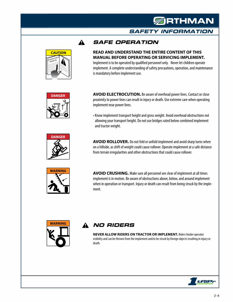
READ AND UNDERSTAND THE ENTIRE CONTENT OF THIS MANUAL BEFORE OPERATING OR SERVICING IMPLEMENT. Implement is to be operated by qualified personnel only. Never let children operate implement. A complete understanding of safety precautions, operation, and maintenance is mandatory before implement use.
AVOID ELECTROCUTION. Be aware of overhead power lines. Contact or close proximity to power lines can result in injury or death. Use extreme care when operating implement near power lines.
• Know implement transport height and gross weight. Avoid overhead obstructions not allowing your transport height. Do not use bridges rated below combined implement and tractor weight.
AVOID ROLLOVER. Do not fold or unfold implement and avoid sharp turns when on a hillside, as shift of weight could cause rollover. Operate implement at a safe distance from terrain irregularities and other obstructions that could cause rollover.
AVOID CRUSHING. Make sure all personnel are clear of implement at all times implement is in motion. Be aware of obstructions above, below, and around implement when in operation or transport. Injury or death can result from being struck by the imple-ment.
NO RIDERSNEVER ALLOW RIDERS ON TRACTOR OR IMPLEMENT. Riders hinder operator visibility and can be thrown from the implement and/or be struck by foreign objects resulting in injury or death.
DANGER
DANGER
2 - 6
SAFETY INFORMATION
PRACTICE SAFE MAINTENANCE
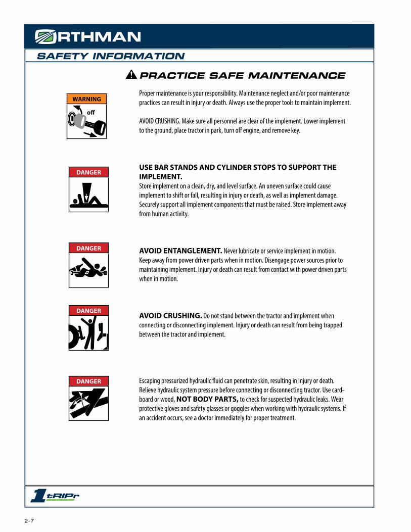
Proper maintenance is your responsibility. Maintenance neglect and/or poor maintenance practices can result in injury or death. Always use the proper tools to maintain implement.
AVOID CRUSHING. Make sure all personnel are clear of the implement. Lower implement to the ground, place tractor in park, turn off engine, and remove key.
USE BAR STANDS AND CYLINDER STOPS TO SUPPORT THE IMPLEMENT.Store implement on a clean, dry, and level surface. An uneven surface could cause implement to shift or fall, resulting in injury or death, as well as implement damage. Securely support all implement components that must be raised. Store implement away from human activity.
AVOID ENTANGLEMENT. Never lubricate or service implement in motion. Keep away from power driven parts when in motion. Disengage power sources prior to maintaining implement. Injury or death can result from contact with power driven parts when in motion.
AVOID CRUSHING. Do not stand between the tractor and implement when connecting or disconnecting implement. Injury or death can result from being trapped between the tractor and implement.
Escaping pressurized hydraulic fluid can penetrate skin, resulting in injury or death. Relieve hydraulic system pressure before connecting or disconnecting tractor. Use card-board or wood, NOT BODY PARTS, to check for suspected hydraulic leaks. Wear protective gloves and safety glasses or goggles when working with hydraulic systems. If an accident occurs, see a doctor immediately for proper treatment.
DANGER
WARNING
off
DANGER
DANGER
DANGER
2 - 7

SAFETY INFORMATION
CAUTION
CAUTION
DANGER
DANGER
PRACTICE SAFE MAINTENANCE
• Never operate a combustion engine in an enclosed area. Make sure there is adequate ventilation. Exhaust fumes can cause asphyxiation.
• Service tires safely. Tire and rim separation can result in serious injury or death. Do not over inflate tires. Only mount or dismount tires if you possess the proper equipment, otherwise contact a trained professional. Always maintain correct tire pressure. Inspect tires and wheels daily. Do not operate tires with inadequate pressure, cuts, visible dam-age, or missing hardware.
• Be extremely careful working around unshielded sharp edges. Injury may result from contact with sharp edges.
• Keep all parts in good condition and properly installed. Replace damaged or missing parts immediately.
• Remove tools and unused parts prior to implement operation.
PREPARE FOR EMERGENCIES
• Be prepared for a fire. Keep a readily accessible fire extinguisher at all times.
• Keep a readily accessible stocked first aid kit and emergency phone numbers for your doctor, hospital, ambulance, and fire department.
• Wear protective clothing and equipment. Wear clothing appropriate for the situation. Protect your eyes, ears, hands, and feet with the use of protective goggles, ear plugs, gloves, boots, etc.
9 1 1
2 - 8

SAFETY INFORMATION
ANHYDROUS AMMONIA - NH3
LIQUID FERTILIZER
ANHYDROUS AMMONIA (NH3) AND LIQUID FERTILIZER APPEARS HARM-
LESS. DIRECT EXPOSURE TO NH3 OR LIQUID FERTILIZER IS EXTREMELY
DANGEROUS AND CAN RESULT IN INJURY AND/OR DEATH.
• Keep a clean supply of water readily accessible in case of exposure to NH3 or liquid fertlizer.
• Wear protective goggles and gloves when working with NH3 or liquid fertilizer. Be sure all
persons involved in the operation are properly trained concerning the dangers and precau-
tions involved in the application of NH3 or liquid fertilizer.
• If you choose to apply NH3 or liquid fertilizer, it is advisable to consult documented informa-
tion regarding safe handling and application of NH3 or liquid fertilizer. Information is avail-
able from the following recognized sources:
1. American National Standards Institute - www.ansi.org - (212) 642-4900
2. Material Safety Data Sheets - MSDS - www.msdsonline.com
3. National Safety Council - www.nsc.org/necas
4. The Fertilizer Institute - www.tfi.org
5. United States Department of Transportation - D.O.T. - www.dot.gov
6. Compressed Gas Association - www.cganet.com
SAFETY NEVER HURTS
READ AND UNDERSTAND THE ENTIRE CONTENT OF THIS MANUAL BEFORE
OPERATING OR SERVICING IMPLEMENT.
• Understand all implement functions.
• Never stand between tractor and implement when connecting or disconnecting implement.
• Be aware of all surroundings before moving implement.
• Operate implement from operator’s seat only.
• Never mount or dismount a moving tractor.
• Never leave engine running when implement is unattended.
• Keep away from power driven parts when in motion.
• Make sure all personnel are clear before lowering implement to the ground.
DANGER
CAUTION
OPERATOR’S
MANUAL
2 - 9
SAFETY INFORMATION
RE
AD
MA
NU
AL
IMP
OR
TAN
T
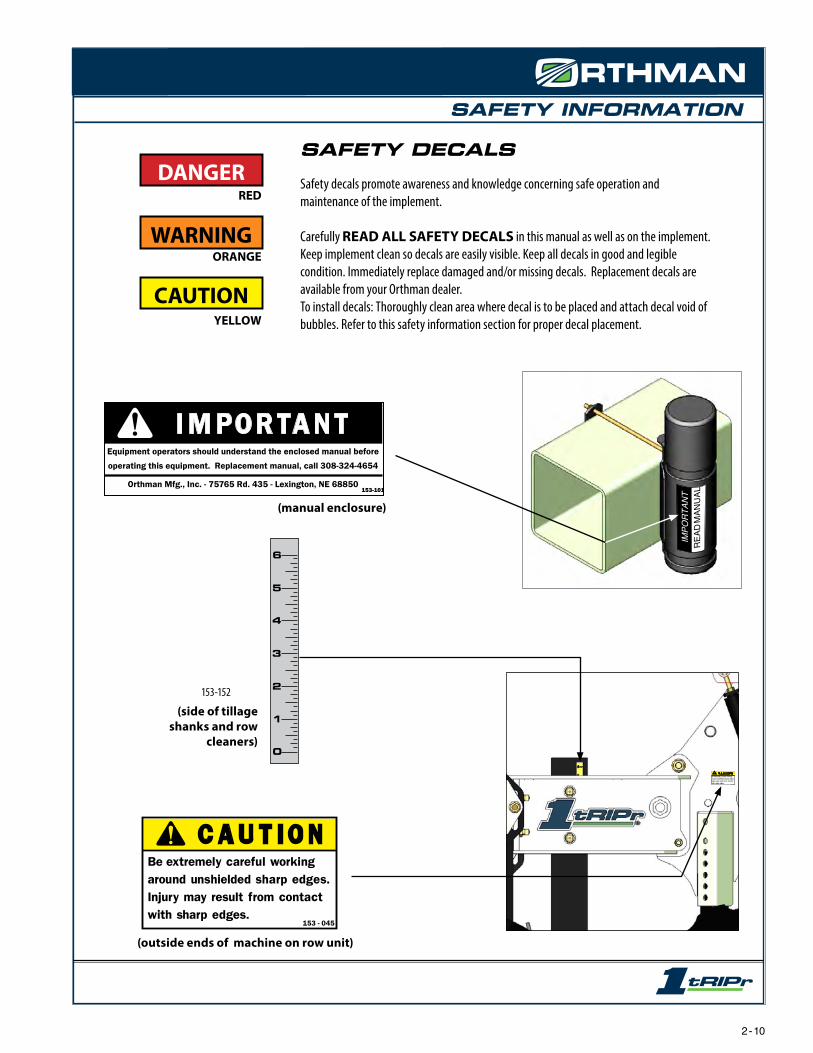
SAFETY DECALS
Safety decals promote awareness and knowledge concerning safe operation and maintenance of the implement.
Carefully READ ALL SAFETY DECALS in this manual as well as on the implement. Keep implement clean so decals are easily visible. Keep all decals in good and legible condition. Immediately replace damaged and/or missing decals. Replacement decals are available from your Orthman dealer.To install decals: Thoroughly clean area where decal is to be placed and attach decal void of bubbles. Refer to this safety information section for proper decal placement.
153-152
0
1
2
3
4
5
6
(side of tillage shanks and row
cleaners)
RED
ORANGE
YELLOW
CAUTION
WARNING
DANGER
C A U T I O NBe extremely careful working around unshielded sharp edges. Injury may result from contact with sharp edges.
153 - 045
153-045.indd 1 1/12/2005 8:49:28 AM
(outside ends of machine on row unit)
(manual enclosure)
2 - 10

SAFETY INFORMATION
ORTHMAN DECALS
153-430(front right and rear left of toolbar)
(outer side of outer row units)
(front left and rear right of toolbar)153-431
153-432
2 - 11

SAFETY INFORMATION
ORTHMAN SERIAL TAG
The Orthman serial tag contains valuable information. The model and serial numbers provide Orthman dealers and the Orthman Service Department with the exact specifica-tions of your implement if any warranty or service issues need to be addressed.
(serial tag location on rigid toolbar)
(serial tag location on single 7 sq. folding toolbar)
153-011
L E X I N G T O N , N E B R A S K A
MODEL
3 0 8 - 3 2 4 - 4 6 5 4
SERIAL# #
(serial tag location on double 7 sq. folding toolbar)
2 - 12

PREPARATION AND SETUP
SHIPPING CONFIGURATIONThe majority of the 1tRIPr® is assembled at Orthman Mfg., Inc. The 1tRIPr® is assembled in an appropriate shipping configuration to ensure transport safety and efficiency from the manufacturer. Installation of optional tooling (if applicable) and adjustment of installed tooling is necessary prior to an initial field trial.
The 1tRIPr® does not come set for field use from the factory. Please refer to Field Settings section of this manual for proper settings.
The shipping configuration provides even implement weight distribution between the depth band coulter assembly and the wavy coulter assemblies. The row cleaner assembly and the tillage shank assembly do not bear implement weight, as illustrated above.
Prior to off-season storage, it is recommended to restore the 1tRIPr® row units to the shipping configura-tion illustrated above to avoid placing weight on the row cleaner or tillage shank assembly. When storing in-season, lower implement very slowly to avoid sharp impact between the storage surface and the tillage shank assembly foot piece.
NOTE: The tillage shank assembly foot piece consists of a hard material to decrease wear and improve field performance. Due to material hardness, sharp impact, excessive weight, etc. can damage the tillage shank assembly foot piece.
Shipping/Storage Surface
Row Cleaner Assembly
Tillage Shank Assembly
CAUTION
C A U T I O NBe extremely careful working around unshielded sharp edges. Injury may result from contact with sharp edges.
153 - 045
153-045.indd 1 1/12/2005 8:49:28 AM
3 - 1
PREPARATION AND SETUP
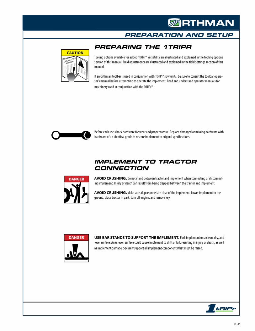
PREPARING THE 1TRIPRTooling options available for added 1tRIPr® versatility are illustrated and explained in the tooling options section of this manual. Field adjustments are illustrated and explained in the field settings section of this manual.
If an Orthman toolbar is used in conjunction with 1tRIPr® row units, be sure to consult the toolbar opera-tor’s manual before attempting to operate the implement. Read and understand operator manuals for machinery used in conjunction with the 1tRIPr®.
Before each use, check hardware for wear and proper torque. Replace damaged or missing hardware with hardware of an identical grade to restore implement to original specifications.
IMPLEMENT TO TRACTOR CONNECTIONAVOID CRUSHING. Do not stand between tractor and implement when connecting or disconnect-ing implement. Injury or death can result from being trapped between the tractor and implement.
AVOID CRUSHING. Make sure all personnel are clear of the implement. Lower implement to the ground, place tractor in park, turn off engine, and remove key.
USE BAR STANDS TO SUPPORT THE IMPLEMENT. Park implement on a clean, dry, and level surface. An uneven surface could cause implement to shift or fall, resulting in injury or death, as well as implement damage. Securely support all implement components that must be raised.
DANGER
DANGER
CAUTION
OPERATOR’S
MANUAL
3 - 2

PREPARATION AND SETUP
STANDARD ROW UNITCOMPONENT IDENTIFICATION
7
10
54
98
6
2
1
3
DIRECTION OF TRAVEL
RIGHT
LEFT
3
NOTE: Right and left as illustrated above and referenced from this point on, is determined by facing the same direction the implement will travel while in use.
1. TOOLBAR. Proven Orthman toolbar design provides unmatched strength.2. MOUNT. A wrap- around mount provides a robust row unit foundation.3. PARALLEL LINKAGES. Parallel linkages allow the row unit to operate independently of the toolbar for consistant depth control in uneven field conditions.4. DOWN PRESSURE SPRINGS. Four adjustable down pressure springs per row unit supply down pressure to assist with row unit tooling soil penetration.5. MAINFRAME. The row unit mainframe serves as the primary mount for row unit tooling.6. DEPTH BAND COULTER ASSEMBLY. The depth band cuts through surface and sub-surface residue to eliminate interference with the shank while it simultanously maintains a precise control of seed-bed depth.7. TAIL SECTION. The tail section houses adjustable tooling.8. ROW CLEANER ASSEMBLY. The row cleaner features rugged notched disc blades to remove plant residue front the strip, clearing a path for rear tooling and the subsequent planter operation.9. TILLAGE SHANK ASSEMBLY. The tillage shank shatters compaction, eliminates subsoil voids, increases water infiltration, and promotes vigorous root growth through all stages of seed develop-ment.10. WAVY COULTER ASSEMBLIES. Wavy coulter assemblies provide “lift and pinch” tillage to capture loosened soil and create a firm consistent strip.
3 - 3


TOOLING OPTIONS AND INSTALLATION
INDIVIDUAL ROW UNITSIn most cases the 1tRIPr® is purchased as a machine and row units will be factory installed to the toolbar. Individual 1tRIPr® row units can be purchased seperate of a toolbar. Use the instructions below to properly mount the 1tRIPr® row unit to a 7 sq. toolbar.
MOUNTING OF ROW UNITSAVOID CRUSHING. Make sure all personnel are clear of the implement. Lower implement to the ground, place tractor in park, turn off engine, and remove key.
USE BAR STANDS TO SUPPORT THE IMPLEMENT. Park implement on a clean, dry, and level surface. An uneven surface could cause implement to shift or fall, resulting in personal injury or death, as well as implement damage. Securely support all implement components that must be raised. Remove buildup of grease, oil, or debris prior to installing row unit mounts.
DANGER
CAUTION
C A U T I O NBe extremely careful working around unshielded sharp edges. Injury may result from contact with sharp edges.
153 - 045
153-045.indd 1 1/12/2005 8:49:28 AM
1. Remove mount from front of parallel lingage of row unit.2. Leave wedge bolt installed, slightly start threads into wedge and position on toolbar. (fig. 1)3. Install U-bolts and snug up evenly top and bottom on each nut until mount is snug on toolbar. (fig. 2)4. Tighten wedge bolt until wedge moves up the ramp and becomes tight against the bottom of the toolbar. (fig. 3) Mount ears should come tight against top of toolbar at this time. (fig. 4) If mount ears do not come tight against top of bar, loosen U-bolts slightly and retry.5. Finish tightening U-bolt nuts evenly. U-bolt nuts are locking nuts and may tighten slowly.6. Install row unit parallel linkage to mount. (fig. 4)7. When properly installed, mount should be square and top ears of mount should both contact top side of toolbar. (fig. 4)8. After initial break in period of field operation, check all hardware for tightness.
NOTE: Recommended tools: Impact wrench, 1 1/8” impact socket, 1 1/8” end wrench. U-bolt flange nuts are locking nuts and tighten slowly.
ParallelLinkage
U-BoltsMount
Fig. 1 Fig. 2 Fig. 3 Fig. 4
Wedge
Wedge Bolt
U-Bolt Nuts
Ramp
Mount Ears
4 - 1

TOOLING OPTIONS AND INSTALLATION
ROW UNIT SET-BACK CLAMPRow unit set-back clamps are recommended on 1tRIPr® machines set at 22” row spacing, and become necessary on machines set at 20” row spacing. Row unit set-back clamps are typically installed on every other row unit across the machine.
MOUNTING SET-BACK CLAMPAVOID CRUSHING. Make sure all personnel are clear of the implement. Lower implement to the ground, place tractor in park, turn off engine, and remove key.
USE BAR STANDS TO SUPPORT THE IMPLEMENT. Park implement on a clean, dry, and level surface. An uneven surface could cause implement to shift or fall, resulting in personal injury or death, as well as implement damage. Securely support all implement components that must be raised. Remove buildup of grease, oil, or debris prior to installing the row unit set-back clamp.
DANGER
CAUTION
1. Remove row unit from traditional mount at front of parallel linkage.2. Remove standard row unit mount. Save Internal Bushings for re-use.3. Install row unit set-back clamp with clamp bolts. Snug clamp bolts tight.4. Use 2 adjustment bolts and washers (if necessary) to set the hole to hole distance to 14”.5. Tighten set-back clamp bolts and adjustment bolts to proper torque (pg. 7 - 2)6. Re-install Busings from original row unit mount into set-back clamp.7. Re-install Row unit parallel linkage to set-back clamp. Grease pivot bushings.
NOTE: Recommended tools: Impact wrench, 1 1/8” impact socket, 1 1/8 end wrenches, 3/4 washers.
C A U T I O NBe extremely careful working around unshielded sharp edges. Injury may result from contact with sharp edges.
153 - 045
153-045.indd 1 1/12/2005 8:49:28 AM
4 - 2
Set-Back Clamp
Bushings
AdjustmentBolt
14”
ClampBolts
TOOLING OPTIONS AND INSTALLATION
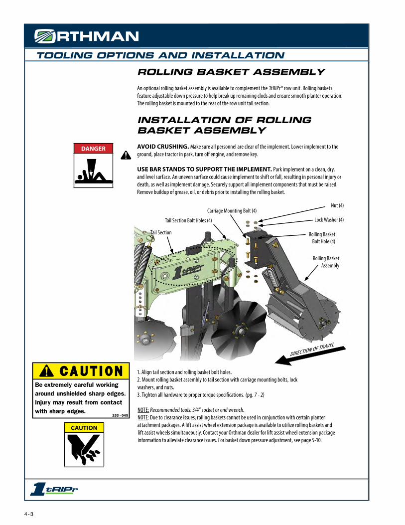
ROLLING BASKET ASSEMBLYAn optional rolling basket assembly is available to complement the 1tRIPr® row unit. Rolling baskets feature adjustable down pressure to help break up remaining clods and ensure smooth planter operation. The rolling basket is mounted to the rear of the row unit tail section.
INSTALLATION OF ROLLING BASKET ASSEMBLYAVOID CRUSHING. Make sure all personnel are clear of the implement. Lower implement to the ground, place tractor in park, turn off engine, and remove key.
USE BAR STANDS TO SUPPORT THE IMPLEMENT. Park implement on a clean, dry, and level surface. An uneven surface could cause implement to shift or fall, resulting in personal injury or death, as well as implement damage. Securely support all implement components that must be raised. Remove buildup of grease, oil, or debris prior to installing the rolling basket.
Carriage Mounting Bolt (4)
Rolling BasketAssembly
Nut (4)
Lock Washer (4)Tail Section Bolt Holes (4)
Rolling BasketBolt Hole (4)
Tail Section
1. Align tail section and rolling basket bolt holes.2. Mount rolling basket assembly to tail section with carriage mounting bolts, lock washers, and nuts.3. Tighten all hardware to proper torque specifications. (pg. 7 - 2)
NOTE: Recommended tools: 3/4” socket or end wrench. NOTE: Due to clearance issues, rolling baskets cannot be used in conjunction with certain planter attachment packages. A lift assist wheel extension package is available to utilize rolling baskets and lift assist wheels simultaneously. Contact your Orthman dealer for lift assist wheel extension package information to alleviate clearance issues. For basket down pressure adjustment, see page 5-10.
DIRECTION OF TRAVEL
DANGER
CAUTION
C A U T I O NBe extremely careful working around unshielded sharp edges. Injury may result from contact with sharp edges.
153 - 045
153-045.indd 1 1/12/2005 8:49:28 AM
4 - 3

TOOLING OPTIONS AND INSTALLATION
MOLE SHANKThe mole shank assembly is integral in achieving all 3 principals of strip-till planting. Ideal Seedbed Preperation, Precision Nutrient Placement and Optimal Root-Zone Conditioning.
NOTE: A depth indicator allows for uniform mole shank assembly depth between row units. Depth indicator decal does not reflect actual tillage depth. Use depth indicator decal as a tool to achieve uniform depth across the implement.
Two adjustable fertilizer tube(s) allow precision fertilizer placement at two seperate depths, if desired, while being protected by hard-surfaced plates.
Precision fertilizer placement provides crop plants with timely fertilizer access to maximize development from germination through maturity.
If combining strip-tillage and planting operations with a Combo Caddy or attachment package, lateral offset of the 1tRIPr® row unit relative to seed placement is recommended to allow fertilizer placement without detriment to seed germination.
NOTE: Refer to (pg. 4 - 9) for mole shank assembly installation instructions.Refer to (pg. 4 - 10 & 4 - 11) for fertilizer tube adjustment/installation instructions.
Depth Indicator
Shank
Foot Piece
Pin Holes(used to support fertilizer tube(s)
Fertilizer Tubes
4 - 4
TOOLING OPTIONS AND INSTALLATION
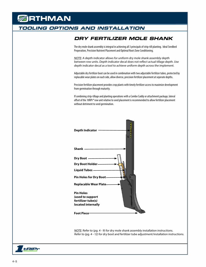
DRY FERTILIZER MOLE SHANKThe dry mole shank assembly is integral in achieving all 3 principals of strip-till planting. Ideal Seedbed Preperation, Precision Nutrient Placement and Optimal Root-Zone Conditioning.
NOTE: A depth indicator allows for uniform dry mole shank assembly depth between row units. Depth indicator decal does not reflect actual tillage depth. Use depth indicator decal as a tool to achieve uniform depth across the implement.
Adjustable dry fertilizer boot can be used in combination with two adjustable fertilizer tubes, protected by replacable wear plates on each side, allow diverse, precision fertilizer placement at seperate depths.
Precision fertilizer placement provides crop plants with timely fertilizer access to maximize development from germination through maturity.
If combining strip-tillage and planting operations with a Combo Caddy or attachment package, lateral offset of the 1tRIPr® row unit relative to seed placement is recommended to allow fertilizer placement without detriment to seed germination.
NOTE: Refer to (pg. 4 - 9) for dry mole shank assembly installation instructions.Refer to (pg. 4 - 12) for dry boot and fertilizer tube adjustment/installation instructions.
Depth Indicator
Shank
Foot Piece
Pin Holes(used to support fertilizer tube(s)located internally
Dry Boot
Liquid Tubes
Dry Boot Holder
Pin Holes for Dry Boot
Replacable Wear Plate
4 - 5

TOOLING OPTIONS AND INSTALLATION
MOLE KNIFE ASSEMBLYThe mole knife assembly is a lower disturbance option of strip-till planting, and aids in Seedbed Preperation, Precision Nutrient Placement and Root-Zone Conditioning.
NOTE: A depth indicator allows for uniform mole knife assembly depth between row units. Depth indicator decal does not reflect actual tillage depth. Use depth indicator decal as a tool to achieve uniform depth across the implment.
Fertilizer tube(s) allow precision fertilizer placement at two depths, if desired. Precision fertilizer placement provides crop plants with timely fertilizer access to maximize development from germination through maturity.
If combining strip-tillage and planting operations with a Combo Caddy or attachment package, lateral offset of the 1tRIPr® row unit relative to seed placement is recommended to allow fertilizer placement without detriment to seed germination.
NOTE: Refer to (pg. 4 - 9) for mole knife assembly installation instructions.Contact your Orthman dealer for additional fertilizer tubes to place fertilizer at two depths.
Depth Indicator
1” x 4” Shank
Mole Knife
Pin Holes(used to support fertilizer tube)
Fertilizer Knife Clamp
Fertilizer Tube
Shear Bolt
4 - 6

TOOLING OPTIONS AND INSTALLATION
NH3 KNIFE ASSEMBLYThe NH3 knife assembly is a option of strip-till planting for Precision NH3 Placement.
NOTE: A depth indicator allows for uniform NH3 knife assembly depth between row units. Depth indicator decal does not reflect actual tillage depth. Use depth indicator decal as a tool to achieve uniform depth across the implment.
Fertilizer tube allows precision fertilizer placement. Precision fertilizer placement provides crop plants with timely fertilizer access to maximize development from germination through maturity.
If combining strip-tillage and planting operations with a Combo Caddy or attachment package, lateral offset of the 1tRIPr® row unit relative to seed placement is recommended to allow fertilizer placement without detriment to seed germination.
NOTE: Refer to (pg. 4 - 9) for NH3 knife assembly installation instructions.
Depth Indicator
1” x 4” Shank
NH3 Knife
Fertilizer Knife Clamp
Fertilizer Tube
Shear Bolt
4 - 7

TOOLING OPTIONS AND INSTALLATION
SHALLOW TILLAGE ASSEMBLYThe shallow tillage tool assembly is a lower disturbance option that aids in Seedbed Preperation.
NOTE: A depth indicator allows for uniform shallow tillage tool assembly depth between row units. Depth indicator decal does not reflect actual tillage depth. Use depth indicator decal as a tool to achieve uniform depth across the implment.
NOTE: Refer to (pg. 4 - 9) for shallow tillage assembly installation instructions.
Depth Indicator
1” x 4” Shank
Wavy Coulters
4 - 8

TOOLING OPTIONS AND INSTALLATION
(MOLE SHANK ASSEMBLY PICTURED)1. Loosen jam nuts and set bolts to provide adequate shank housing clearance for the shank to be inserted in the
bottom side of the tail.2. Insert shank into shank housing. 3. Tighten set bolts and jam nuts to secure tillage shank assembly to tail section.4. Tighten hardware to proper torque specifications. (pg. 7 - 2)
NOTE: A depth indicator allows for uniform tillage shank assembly depth between row units. Depth indicator decal does not reflect actual tillage depth. Use depth indicator decal as a tool to achieve uniform depth across the implement.
NOTE: Tail Flange nuts are welded to both sides of the tail. Jam nuts and set bolts can be moved to the opposite side for ease of adjustment.
NOTE: Recommended tools: Jam Nut - 15/16 end wrench, Set Bolt - 5/8 eight point socket. (3/4 end wrench will substitute for the 5/8 eight point socket, although not recommended)
INSTALLATION1X4 SHANK ASSEMBLY(MOLE SHANKS, KNIVES AND SHALLOW TILLAGE)
AVOID CRUSHING. Make sure all personnel are clear of the implement. Lower implement to support blocks to attain proper shank installation height, place tractor in park, turn off engine, and remove key.
USE BAR STANDS TO SUPPORT THE IMPLEMENT. Park implement on a clean, dry, and level surface. An uneven surface could cause implement to shift or fall, resulting in personal injury or death, as well as implement damage. Securely support all implement components that must be raised. Remove buildup of grease, oil, or debris prior to installing the tillage shank.
DIRECTION OF TRAVEL
Shank Housing
Tail Section
Flange Nut (2)(welded to tail) Jam Nut (2)
Set Bolt (2)
DANGER
CAUTION
1X4 Shank
C A U T I O NBe extremely careful working around unshielded sharp edges. Injury may result from contact with sharp edges.
153 - 045
153-045.indd 1 1/12/2005 8:49:28 AM
4 - 9

TOOLING OPTIONS AND INSTALLATION
INSTALLATIONMOLE SHANK ASSEMBLY FERTILIZER TUBEIf you choose to apply NH3 or liquid fertilizer, it is advisable to consult documented information regarding safe handling and application of NH3 or liquid fertilizer. Refer to recognized sources. (pg. 2 - 9)
AVOID CRUSHING. Make sure all personnel are clear of the implement. Lower implement to support blocks to attain proper shank installation height for fertilizer tubes, place tractor in park, turn off engine, and remove key.
USE BAR STANDS TO SUPPORT THE IMPLEMENT. Park implement on a clean, dry, and level surface. An uneven surface could cause implement to shift or fall, resulting in personal injury or death, as well as implement damage. Securely support all implement components that must be raised. Remove buildup of grease, oil, or debris prior to installing the fertilizer tubes.
1. Distinguish roll pin holes for desired fertilizer placement depth.2. Insert fertilizer tubes between side plates.3. Align desired roll pin holes and fertilizer tube mount tab.4. Insert roll pin through side plate roll pin holes and fertilizer tube mount tab to secure fertilizer tube.
NOTE: The uppermost roll pin holes and upper roll pin may be used to support the upper portion of the fertilizer tube.
Shank
Roll PinHoles
Fertilizer Tubes
Fertilizer TubeMount Tab
Side Plate
Roll Pin
Direction of Travel
DANGER
CAUTION
DANGER
Cross-Sectionof mole shank
C A U T I O NBe extremely careful working around unshielded sharp edges. Injury may result from contact with sharp edges.
153 - 045
153-045.indd 1 1/12/2005 8:49:28 AM
4 - 10

TOOLING OPTIONS AND INSTALLATION
INSTALLATION - MOLE SHANK ASSEMBLY WITH OPTIONAL DRY FERTILIZER BOOTIf you choose to apply NH3 or liquid fertilizer, or dry fertilizer it is advisable to consult documented information regarding safe handling and application of NH3 or liquid fertilizer. Refer to recognized sources. (pg. 2 - 9)
AVOID CRUSHING. Make sure all personnel are clear of the implement. Lower implement to support blocks to attain proper shank installation height for fertilizer tubes, place tractor in park, turn off engine, and remove key.
USE BAR STANDS TO SUPPORT THE IMPLEMENT. Park implement on a clean, dry, and level surface. An uneven surface could cause implement to shift or fall, resulting in personal injury or death, as well as implement damage. Securely support all implement components that must be raised. Remove buildup of grease, oil, or debris prior to installing the fertilizer boot.
1. Distinguish roll pin holes for desired fertilizer placement depth.2. Insert fertilizer tube, and or dry fertilizer boot between side plates.3. Align desired roll pin holes and fertilizer tube mount tab.4. Insert roll pin through side plate roll pin holes and fertilizer tube and or dry fertilizer boot mount tabs to
secure tube and or boot.
NOTE: the uppermost roll pin holes and upper roll pin may be used to support the upper portion of the fertilizer tube and or boot.
Shank
Roll PinHoles
Fertilizer Tube
Fertilizer TubeMount Tab
Side Plate
Roll PinDirection of Travel
CAUTION
Cross-Section of mole shank with optional dry boot
Dry Boot
Dry Boot Holder
DANGER
DANGER
C A U T I O NBe extremely careful working around unshielded sharp edges. Injury may result from contact with sharp edges.
153 - 045
153-045.indd 1 1/12/2005 8:49:28 AM
4 - 11

TOOLING OPTIONS AND INSTALLATION
INSTALLATIONDRY MOLE SHANK ASSEMBLY FERTILIZER TUBE AND BOOTIf you choose to apply NH3 or liquid fertilizer, it is advisable to consult documented information regarding safe handling and application of NH3 or liquid fertilizer. Refer to recognized sources. (pg. 2 - 9)
AVOID CRUSHING. Make sure all personnel are clear of the implement. Lower implement to support blocks to attain proper shank installation height for fertilizer tubes, place tractor in park, turn off engine, and remove key.
USE BAR STANDS TO SUPPORT THE IMPLEMENT. Park implement on a clean, dry, and level surface. An uneven surface could cause implement to shift or fall, resulting in personal injury or death, as well as implement damage. Securely support all implement components that must be raised. Remove buildup of grease, oil, or debris prior to installing the fertilizer tubes.
1. Remove replacable side plates to access roll pin holes.2. Distinguish roll pin holes for desired fertilizer placement depth.3. Insert fertilizer tubes between side plates.4. Align desired roll pin holes and fertilizer tube mount tab.5. Insert roll pin through side plate roll pin holes and fertilizer tube and or dry fertilizer boot holder to secure tube and or boot.6. Install roll pin between replacable side plates to secure lower end of dry boot.
NOTE: The uppermost roll pin holes and upper roll pin may be used to support the upper portion of the fertilizer tube.
Shank
Roll PinHoles
Fertilizer Tubes
Fertilizer TubeMount Tab
Replacable Side Plate
Roll Pin
Direction of Travel
DANGER
CAUTION
DANGER
Cross-Sectionof dry mole shank
Roll Pin
Roll Pin
Dry Boot Holder
Dry Boot
C A U T I O NBe extremely careful working around unshielded sharp edges. Injury may result from contact with sharp edges.
153 - 045
153-045.indd 1 1/12/2005 8:49:28 AM
4 - 12

TOOLING OPTIONS AND INSTALLATION
INSTALLATION - AIR DIFFUSER AND AIR DIFFUSER MOUNTThere are two different types of Orthman Air Diffuser mounts.
Mount style 1 is only for use with 1tRIPr® row units that have been produced in 2009 or later. To install this mount remove two 5/16” carriage bolts from the Diffuser and mount package. Align two square bolt holes on mount bracket with two square bolt holes on row unit tail. Tighten with 1/2” end wrench. This mount can be utilized on either side of the tail. The Air Diffuser and mount package comes from Orthman Manufacturing ready to install on the left side of the 1tRIPr® row unit tail. Diffuser mount will need to be removed from the diffuser and flipped over to be installed on the right side.
Mount style 2 is for use with any 1tRIPr® row unit ever produced, and will most likely be received if you have purchased an Orthman Atlas Lifting Cart, or other machine lifting device. This is due to the fact the purchasers of these lifting devices may already own 1tRIPr® machines produced before 2009 that do not have the mount holes in the tail for mount style 1. Contact Orthman Manufacturing for Diffuser mount options. To install this mount, loosen jam nuts and set screws and slide the round part over the top of the left or right round wavy coulter shank, set the preferred angle, and then re-tighten the set screws and jam nuts. This Air Diffuser and mount package may come assembled from Orthman Manufacturing ready to install on the left side of the 1tRIPr® row unit. Diffuser mount may need to be removed from the diffuser and flipped over to be installed on the right side.
4 - 13

TOOLING OPTIONS AND INSTALLATION
DIRECTION OF TRAVEL
Fertilizer Tube
Fertilizer Tube Mount Tab
Roll Pin
Roll Pin Holes (3 per side plate)
Shank
1. Distinguish roll pin holes for desired fertilizer placement depth.2. Insert fertilizer tube between side plates. (see inset)3. Align desired roll pin holes and fertilizer tube mount tab.4. Insert roll pin through side plate roll pin holes and fertilizer tube mount tab to secure fertil-
izer tube.
INSTALLATION - MOLE KNIFE ASSEMBLY FERTILIZER TUBEIf you choose to apply NH3, it is advisable to consult documented information regarding safe handling and application of NH3. Refer to recognized sources. (pg. 2 - 9)
AVOID CRUSHING. Make sure all personnel are clear of the implement. Lower implement to the ground, place tractor in park, turn off engine, and remove key.
USE BAR STANDS TO SUPPORT THE IMPLEMENT. Park implement on a clean, dry, and level surface. An uneven surface could cause implement to shift or fall, resulting in personal injury or death, as well as implement damage. Securely support all implement components that must be raised. Remove buildup of grease, oil, or debris prior to installing the mole knife.
Inset
Side Plates
DANGER
CAUTION
DANGER
C A U T I O NBe extremely careful working around unshielded sharp edges. Injury may result from contact with sharp edges.
153 - 045
153-045.indd 1 1/12/2005 8:49:28 AM
4 - 14

TOOLING OPTIONS AND INSTALLATION
INSTALLATION MOLE SHANK SHIN CAPAVOID CRUSHING. Make sure all personnel are clear of the implement. Lower implement to the ground, place tractor in park, turn off engine, and remove key.
USE BAR STANDS TO SUPPORT THE IMPLEMENT. Park implement on a clean, dry, and level surface. An uneven surface could cause implement to shift or fall, resulting in personal injury or death, as well as implement damage. Securely support all implement components that must be raised. Remove buildup of grease, oil, or debris prior to installing the mole knife.
DANGER
1. Remove upper roll pin from foot piece. (be careful not to strike foot piece ear with hammer)2. Fit shin cap over top ear of foot piece and align holes.3. Insert bolt thru shin cap, foot piece, and shank using washers on each side.
4. Tighten hardware, being careful not to overtighten so much to break foot piece ear.
CAUTION
Properly Installed
Shin Cap Package
Roll Pin
C A U T I O NBe extremely careful working around unshielded sharp edges. Injury may result from contact with sharp edges.
153 - 045
153-045.indd 1 1/12/2005 8:49:28 AM
4 - 15

TOOLING OPTIONS AND INSTALLATION
Linkage BaseMounting Holes
Trip LinkagePivot Points
INSTALLATION - AUTOMATIC RESET TRIP LINKAGEOne of the most innovative Orthman 1tRIPr® row unit accessories is the Automatic Reset Trip Linkage. This allows the row unit to be tripped by underground obstructions and then automatically reset. This helps protect the shank and wavy coulter tooling. The Automatic Reset “AR” Linkage will be installed on your 1tRIPr® machine from the factory if ordered with that option. The AR Linkage can also be ordered as a package and adapted to any standard row unit made in 2009 or later.
AVOID CRUSHING. Make sure all personnel are clear of the implement. Lower implement to the ground, place tractor in park, turn off engine, and remove key.
USE BAR STANDS TO SUPPORT THE IMPLEMENT. Park implement on a clean, dry, and level surface. An uneven surface could cause implement to shift or fall, resulting in personal injury or death, as well as implement damage. Securely support all implement components that must be raised. Remove buildup of grease, oil, or debris prior to adjusting.
If installing the AR linkage to a 1tRIPr® row unit please follow these instructions.If AR linkage is already installed onto your machine’s row units, please advance to the AR linkage field settings section.
1. Locate the trip linkage pivot points on the tail and mainframe sections, and the linkage base mounting holes on the tail.
Remove main frame pivot
Bolt/nut and crush sleeve
Main pivot bolt/nutand crush sleeve Remove carriage
bolts (8) and nuts.
Base Plate
2. The AR Linkage package you receive should be mostly assembled. Remove the ¾”x 3 1/2” long main frame pivot bolt and crush sleeve. Also remove the eight ½” x 1 ¼” carriage bolts that are in the base plate. Locate the 1” x 5” long main pivot bolt with nut and crush sleeve.
DANGER
4 - 16
TOOLING OPTIONS AND INSTALLATION
AVOID CRUSHING. Make sure all personnel are clear of the implement. Lower implement to the ground, place tractor in park, turn off engine, and remove key.
USE BAR STANDS TO SUPPORT THE IMPLEMENT. Park implement on a clean, dry, and level surface. An uneven surface could cause implement to shift or fall, resulting in personal injury or death, as well as implement damage. Securely support all implement components that must be raised. Remove buildup of grease, oil, or debris prior to adjusting.
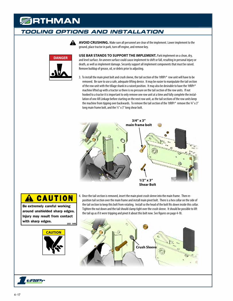
3. To install the main pivot bolt and crush sleeve, the tail section of the 1tRIPr® row unit will have to be removed. Be sure to use a safe, adequate lifting device. It may be easier to manipulate the tail section of the row unit with the tillage shank in a raised position. It may also be desirable to have the 1tRIPr® machine lifted up with a tractor so there is no pressure on the tail section of the row units. If not hooked to a tractor it is important to only remove one row unit at a time and fully complete the instal-lation of one AR Linkage before starting on the next row unit, as the tail sections of the row units keep the machine from tipping over backwards. To remove the tail section of the 1tRIPr® remove the ¾” x 3” long main frame bolt, and the ½” x 3” long shear bolt.
4. Once the tail section is removed, insert the main pivot crush sleeve into the main frame. Then re-position tail section over the main frame and install main pivot bolt. There is a hex collar on the side of the tail section to keep this bolt from rotating. Install so the head of the bolt fits down inside this collar. Tighten the nut down and the tail should clamp tight over the crush sleeve. It should be possible to lift the tail up as if it were tripping and pivot it about this bolt now. See figures on page 4-18.
3/4” x 3”main frame bolt
1/2” x 3”Shear Bolt
Crush Sleeve
DANGER
CAUTION
C A U T I O NBe extremely careful working around unshielded sharp edges. Injury may result from contact with sharp edges.
153 - 045
153-045.indd 1 1/12/2005 8:49:28 AM
4- 17

TOOLING OPTIONS AND INSTALLATION
Main pivothex collarDANGER
4 - 18

TOOLING OPTIONS AND INSTALLATION
AVOID CRUSHING. Make sure all personnel are clear of the implement. Lower implement to the ground, place tractor in park, turn off engine, and remove key.
USE BAR STANDS TO SUPPORT THE IMPLEMENT. Park implement on a clean, dry, and level surface. An uneven surface could cause implement to shift or fall, resulting in personal injury or death, as well as implement damage. Securely support all implement components that must be raised. Remove buildup of grease, oil, or debris prior to adjusting.
5. After checking that the tail section will pivot and the pivot bolt is tightened it is advisable to re-install ¾” x 3” long main frame bolt. This will keep the tail positioned properly for the rest of the installation and serve as a safety pin so the unit will not accidentally trip while someone is working on it. Be sure to remove this bolt when installation is completed or trip linkage will not function.
Trip Linkage Assembly
Install Crush Sleeve
6. Install crush sleeve into main frame, and then lower trip linkage assembly onto the tail section. Line up the eight bolt holes in the tail section plate and install 8 carriage bolts.
Re-install for safety during installation
DANGER
4 - 19

TOOLING OPTIONS AND INSTALLATION
Measure and return spring tension to the factory provided dis-tance once complete
Front linkage pivot bolt
Remove this bolt once completeSpring tension bolts
7. Once the carriage bolts are tightened it may be necessary to loosen the spring tension bolts, and/or use an alignment punch to install the front linkage pivot bolt.
Be sure to measure distance of spring tension before loosening it in order to return it to its factory setting once the front linkage pivot bolt is installed.
Once trip linkage mounting bolts are tight and spring tension is returned to factory setting, remove ¾” x 3” long main frame bolt that was installed for safety in step 5. The AR Linkage installation is now complete.
AVOID CRUSHING. Make sure all personnel are clear of the implement. Lower implement to the ground, place tractor in park, turn off engine, and remove key.
USE BAR STANDS TO SUPPORT THE IMPLEMENT. Park implement on a clean, dry, and level surface. An uneven surface could cause implement to shift or fall, resulting in personal injury or death, as well as implement damage. Securely support all implement components that must be raised. Remove buildup of grease, oil, or debris prior to adjusting.
DANGER
4 - 20
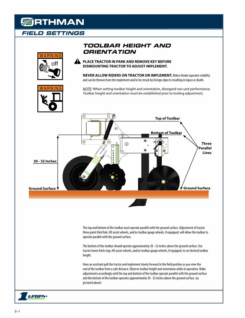
FIELD SETTINGS
Ground Surface
30 - 32 Inches
Three Parallel
Lines
Top of Toolbar
Bottom of Toolbar
Ground Surface
The top and bottom of the toolbar must operate parallel with the ground surface. Adjustment of tractor three point third link, lift assist wheels, and/or toolbar gauge wheels, if equipped, will allow the toolbar to operate parallel with the ground surface.
The bottom of the toolbar should operate approximately 30 - 32 inches above the ground surface. Use tractor lower hitch stop, lift assist wheels, and/or toolbar gauge wheels, if equipped, to set desired toolbar height.
Have an assistant pull the tractor and implement slowly forward in the field position as you view the end of the toolbar from a safe distance. Observe toolbar height and orientation while in operation. Make adjustments accordingly until the top and bottom of the toolbar operate parallel with the ground surface and the bottom of the toolbar operates approximately 30 - 32 inches above the ground surface. (as pictured above)
TOOLBAR HEIGHT AND ORIENTATIONPLACE TRACTOR IN PARK AND REMOVE KEY BEFOREDISMOUNTING TRACTOR TO ADJUST IMPLEMENT.
NEVER ALLOW RIDERS ON TRACTOR OR IMPLEMENT. Riders hinder operator visibility and can be thrown from the implement and/or be struck by foreign objects resulting in injury or death.
NOTE: When setting toolbar height and orientation, disregard row unit performance. Toolbar height and orientation must be established prior to tooling adjustment.
W A R N I N G
offW A R N I N G
5 - 1

FIELD SETTINGS
30 - 32 Inches
Bottom of Toolbar - parallel to ground surface
Ground Surface
Linkage - parallel to ground surface or slightly angled down
TOOLBAR HEIGHT AND ORIENTATIONPLACE TRACTOR IN PARK AND REMOVE KEY BEFOREDISMOUNTING TRACTOR TO ADJUST IMPLEMENT.
NEVER ALLOW RIDERS ON TRACTOR OR IMPLEMENT. Riders hinder operator visibility and can be thrown from the implement and/or be struck by foreign objects resulting in injury or death.
After desired toolbar height and orientation is established, set tractor lower hitch stop, lift assist wheels, and/or toolbar gauge wheels, if equipped.
NOTE: Larger implements may require lift assist wheels and/or toolbar gauge wheels to support toolbar weight. Lift assist wheels and/or toolbar gauge wheels displace a portion of toolbar weight to allow maximum parallel linkage travel.
NOTE: Smaller implements may operate without lift assist wheels and/or toolbar gauge wheels. The tractor hitch will bear a portion of the toolbar weight by setting a lower hitch stop on the tractor three point hitch control.
ROW UNIT DEPTHEffectively, the depth band coulter assembly provides consistent row unit tooling depth by governing soil penetration. Adjustable down pressure springs supply row unit down pressure to assist with row unit soil penetration. Parallel linkages, with the ability to travel vertically, allow row units to operate independent of the toolbar. The depth band, down pressure springs, and parallel linkages should allow the toolbar to serve as a towing device, allowing uniform tillage despite terrain variations.
For the toolbar to serve as a towing device, the ground surface, the toolbar and linkage must generally operate parallel to one another when in the field position. (In most field conditions the linkage will operate at a slight downward angle.) The depth band coulter assembly should allow the toolbar to operate at the desired height and provide consistent row unit tooling depth by governing soil penetration. It is important to arrive at the setting illustrated above so further tooling adjustments will be uniform.
WARNING
off
WARNING
5 - 2
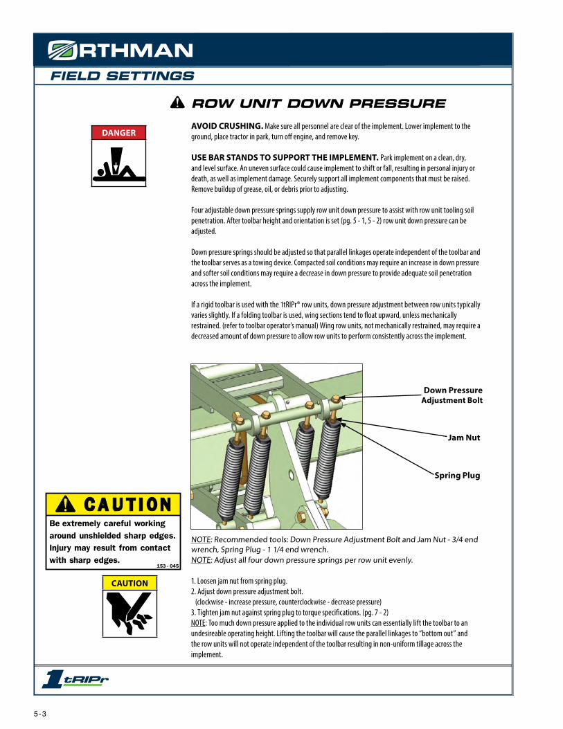
FIELD SETTINGS
ROW UNIT DOWN PRESSUREAVOID CRUSHING. Make sure all personnel are clear of the implement. Lower implement to the ground, place tractor in park, turn off engine, and remove key.
USE BAR STANDS TO SUPPORT THE IMPLEMENT. Park implement on a clean, dry, and level surface. An uneven surface could cause implement to shift or fall, resulting in personal injury or death, as well as implement damage. Securely support all implement components that must be raised. Remove buildup of grease, oil, or debris prior to adjusting.
Four adjustable down pressure springs supply row unit down pressure to assist with row unit tooling soil penetration. After toolbar height and orientation is set (pg. 5 - 1, 5 - 2) row unit down pressure can be adjusted.
Down pressure springs should be adjusted so that parallel linkages operate independent of the toolbar and the toolbar serves as a towing device. Compacted soil conditions may require an increase in down pressure and softer soil conditions may require a decrease in down pressure to provide adequate soil penetration across the implement.
If a rigid toolbar is used with the 1tRIPr® row units, down pressure adjustment between row units typically varies slightly. If a folding toolbar is used, wing sections tend to float upward, unless mechanically restrained. (refer to toolbar operator’s manual) Wing row units, not mechanically restrained, may require a decreased amount of down pressure to allow row units to perform consistently across the implement.
NOTE: Recommended tools: Down Pressure Adjustment Bolt and Jam Nut - 3/4 end wrench, Spring Plug - 1 1/4 end wrench.NOTE: Adjust all four down pressure springs per row unit evenly.
1. Loosen jam nut from spring plug.2. Adjust down pressure adjustment bolt. (clockwise - increase pressure, counterclockwise - decrease pressure)3. Tighten jam nut against spring plug to torque specifications. (pg. 7 - 2)NOTE: Too much down pressure applied to the individual row units can essentially lift the toolbar to an undesireable operating height. Lifting the toolbar will cause the parallel linkages to “bottom out” and the row units will not operate independent of the toolbar resulting in non-uniform tillage across the implement.
Down Pressure Adjustment Bolt
Spring Plug
Jam Nut
DANGER
CAUTION
C A U T I O NBe extremely careful working around unshielded sharp edges. Injury may result from contact with sharp edges.
153 - 045
153-045.indd 1 1/12/2005 8:49:28 AM
5 - 3

FIELD SETTINGS
ROW CLEANER ASSEMBLY DEPTH
The row cleaner assembly reduces field residue directly behind the depth band coulter assembly prior to the arrival of rearward tooling. The row cleaner assembly can be vertically pin adjusted in 1/4 inch incre-ments.
AVOID CRUSHING. Make sure all personnel are clear of the implement. Lower implement to the ground, place tractor in park, turn off engine, and remove key.
USE BAR STANDS TO SUPPORT THE IMPLEMENT. Park implement on a clean, dry, and level surface. An uneven surface could cause implement to shift or fall, resulting in injury or death, as well as implement damage. Securely support all implement components that must be raised. Remove buildup of grease, oil, or debris prior to adjusting the trash opener assembly.
NOTE: Recommended row cleaner depth is approximately 1/2 inch below soil surface to gently remove surface residue with minimal soil disturbance. Row cleaners are often removed when operating in a low residue cover crop such as
drilled wheat, alfalfa, beans, etc.
1. Remove hairpin from depth adjustment pin.2. Physically support weight of row cleaner assembly.3. Remove depth adjustment pin from tail section and shank.4. Vertically adjust row cleaner assembly to desired depth.5. Insert depth adjustment pin through receiver tube. Replace hairpin in depth adjustment pin.
NOTE: A depth indicator allows for uniform row cleaner assembly depth between row units. Depth indicator decal does not reflect actual tillage depth. Use depth indicator decal as a tool to achieve uniform depth across the implement.
Hairpin
Inset (left side view)
Tail Section
Shank
Row Cleaner AssemblyDIRECTION OF TRAVEL
(right side view)
Depth Adjustment Pin
DANGER
CAUTION
C A U T I O NBe extremely careful working around unshielded sharp edges. Injury may result from contact with sharp edges.
153 - 045
153-045.indd 1 1/12/2005 8:49:28 AM
5 - 4
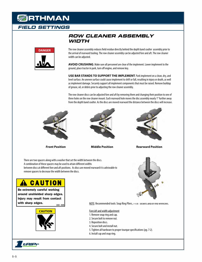
FIELD SETTINGS
Middle Position Rearward PositionFront Position
ROW CLEANER ASSEMBLY WIDTH
The row cleaner assembly reduces field residue directly behind the depth band coulter assembly prior to the arrival of rearward tooling. The row cleaner assembly can be adjusted fore and aft. The row cleaner width can be adjusted.
AVOID CRUSHING. Make sure all personnel are clear of the implement. Lower implement to the ground, place tractor in park, turn off engine, and remove key.
USE BAR STANDS TO SUPPORT THE IMPLEMENT. Park implement on a clean, dry, and level surface. An uneven surface could cause implement to shift or fall, resulting in injury or death, as well as implement damage. Securely support all implement components that must be raised. Remove buildup of grease, oil, or debris prior to adjusting the row cleaner assembly.
The row cleaner discs can be adjusted fore and aft by removing them and changing their position to one of three holes on the row cleaner mount. Each rearward hole moves the disc assembly nearly 1” further away from the depth band coulter. As the discs are moved rearward the distance between the discs will increase.
There are two spacers along with a washer that set the width between the discs.A combination of these spacers may be used to attain different widths between discs at different fore and aft positions. As discs are moved rearward it is adviseable to remove spacers to decrease the width between the discs.
NOTE: Recommended tools: Snap Ring Pliers, 1-1/8” sockets and/or end wrenches.
Fore/aft and width adjustment1. Remove snap ring and cap.2. Secure bolt to remove nut.3. Reposition discs.4. Secure bolt and install nut.5. Tighten all hardware to proper tourque specifications (pg. 7-2).6. Install cap and snap ring.
DANGER
CAUTION
C A U T I O NBe extremely careful working around unshielded sharp edges. Injury may result from contact with sharp edges.
153 - 045
153-045.indd 1 1/12/2005 8:49:28 AM
5 - 5
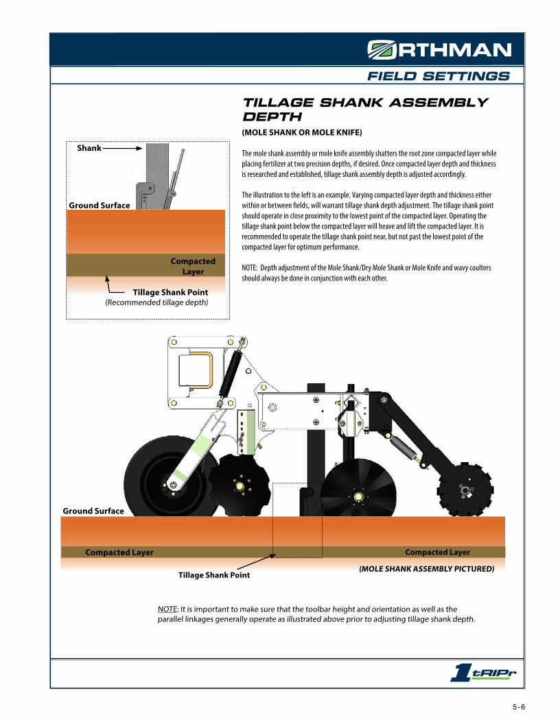
FIELD SETTINGS
Ground Surface
Compacted Layer Compacted Layer
Tillage Shank Point(MOLE SHANK ASSEMBLY PICTURED)
TILLAGE SHANK ASSEMBLY DEPTH(MOLE SHANK OR MOLE KNIFE)
The mole shank assembly or mole knife assembly shatters the root zone compacted layer while placing fertilizer at two precision depths, if desired. Once compacted layer depth and thickness is researched and established, tillage shank assembly depth is adjusted accordingly.
The illustration to the left is an example. Varying compacted layer depth and thickness either within or between fields, will warrant tillage shank depth adjustment. The tillage shank point should operate in close proximity to the lowest point of the compacted layer. Operating the tillage shank point below the compacted layer will heave and lift the compacted layer. It is recommended to operate the tillage shank point near, but not past the lowest point of the compacted layer for optimum performance.
NOTE: Depth adjustment of the Mole Shank/Dry Mole Shank or Mole Knife and wavy coulters should always be done in conjunction with each other.
NOTE: It is important to make sure that the toolbar height and orientation as well as the parallel linkages generally operate as illustrated above prior to adjusting tillage shank depth.
Compacted Layer
Shank
Tillage Shank Point(Recommended tillage depth)
Ground Surface
5 - 6
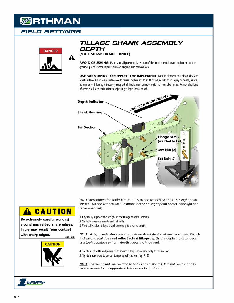
FIELD SETTINGS
TILLAGE SHANK ASSEMBLY DEPTH(MOLE SHANK OR MOLE KNIFE)
AVOID CRUSHING. Make sure all personnel are clear of the implement. Lower implement to the ground, place tractor in park, turn off engine, and remove key.
USE BAR STANDS TO SUPPORT THE IMPLEMENT. Park implement on a clean, dry, and level surface. An uneven surface could cause implement to shift or fall, resulting in injury or death, as well as implement damage. Securely support all implement components that must be raised. Remove buildup of grease, oil, or debris prior to adjusting tillage shank depth.
NOTE: Recommended tools: Jam Nut - 15/16 end wrench, Set Bolt - 5/8 eight point socket. (3/4 end wrench will substitute for the 5/8 eight point socket, although not recommended)
1. Physically support the weight of the tillage shank assembly.2. Slightly loosen jam nuts and set bolts.3. Vertically adjust tillage shank assembly to desired depth.
NOTE: A depth indicator allows for uniform shank depth between row units. Depth indicator decal does not reflect actual tillage depth. Use depth indicator decal as a tool to achieve uniform depth across the implment.
4. Tighten set bolts and jam nuts to secure tillage shank assembly to tail section.5. Tighten hardware to proper torque specifications. (pg. 7- 2)
NOTE: Tail Flange nuts are welded to both sides of the tail. Jam nuts and set bolts can be moved to the opposite side for ease of adjustment.
DIRECTION OF TRAVEL
Shank Housing
Tail Section
Flange Nut (2)(welded to tail) Jam Nut (2)
Set Bolt (2)
Depth Indicator
DANGER
CAUTION
C A U T I O NBe extremely careful working around unshielded sharp edges. Injury may result from contact with sharp edges.
153 - 045
153-045.indd 1 1/12/2005 8:49:28 AM
5 - 7

FIELD SETTINGS
WAVY COULTER ASSEMBLYDEPTH AND WIDTHWavy coulter assemblies provide “lift and pinch” action to incorporate field residue, till, and firm the seedbed.
AVOID CRUSHING. Make sure all personnel are clear of the implement. Lower implement to the ground, place tractor in park, turn off engine, and remove key.
USE BAR STANDS TO SUPPORT THE IMPLEMENT. Park implement on a clean, dry, and level surface. An uneven surface could cause implement to shift or fall, resulting in injury or death, as well as implement damage. Securely support all implement components that must be raised. Remove buildup of grease, oil, or debris prior to adjusting wavy coulter assembly.
NOTE: Recommended tools: Jam Nut and Front Flange Nut - 15/16 end wrench, Set Bolt - 5/8 eight point socket, (3/4 end wrench will substitute for the 5/8 eight point socket, although not recommended)
DEPTH ADJUSTMENT1. Physically support the weight of the wavy coulter assembly.2. Slightly loosen shank clamp front flange nut.3. Vertically adjust wavy coulter assembly to desired depth.4. Tighten front flange nut to torque specifications. (pg. 7 - 2)WIDTH ADJUSTMENT1. Slightly loosen left hand and right hand jam nuts and set bolts.2. Laterally adjust wavy coulter assemblies and diamond cross tubes to desired width.3. Tighten left hand and right hand set bolts and jam nuts.4. Tighten all hardware to proper torque specifications. (pg. 7 - 2)
Diamond Cross Tube
Shank Clamp
Front Flange
Nut
DIRECTION OF TRAVEL
Set Bolts and Jam Nuts
RIght Hand Wavy Coulter Assembly
Left Hand Wavy Coulter Assembly
Diamond Cross Tube
Shank Clamp
Front Flange Nut
DIRECTION OF TRAVEL
Clamp
DANGER
CAUTION
C A U T I O NBe extremely careful working around unshielded sharp edges. Injury may result from contact with sharp edges.
153 - 045
153-045.indd 1 1/12/2005 8:49:28 AM
5 - 8
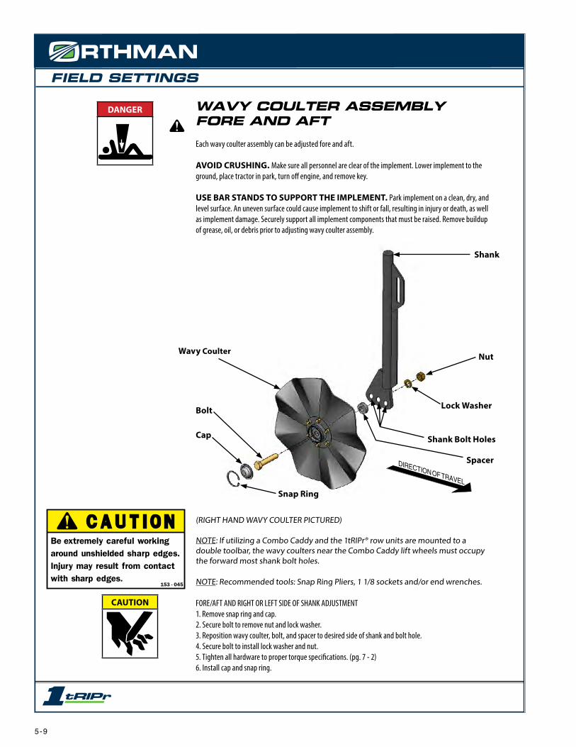
FIELD SETTINGS
DIRECTION OF TRAVEL
Wavy Coulter
Shank
Shank Bolt Holes
Nut
Lock Washer
Spacer
Bolt
Cap
Snap Ring
WAVY COULTER ASSEMBLY FORE AND AFTEach wavy coulter assembly can be adjusted fore and aft.
AVOID CRUSHING. Make sure all personnel are clear of the implement. Lower implement to the ground, place tractor in park, turn off engine, and remove key.
USE BAR STANDS TO SUPPORT THE IMPLEMENT. Park implement on a clean, dry, and level surface. An uneven surface could cause implement to shift or fall, resulting in injury or death, as well as implement damage. Securely support all implement components that must be raised. Remove buildup of grease, oil, or debris prior to adjusting wavy coulter assembly.
(RIGHT HAND WAVY COULTER PICTURED)
NOTE: If utilizing a Combo Caddy and the 1tRIPr® row units are mounted to a double toolbar, the wavy coulters near the Combo Caddy lift wheels must occupy the forward most shank bolt holes.
NOTE: Recommended tools: Snap Ring Pliers, 1 1/8 sockets and/or end wrenches.
FORE/AFT AND RIGHT OR LEFT SIDE OF SHANK ADJUSTMENT1. Remove snap ring and cap.2. Secure bolt to remove nut and lock washer. 3. Reposition wavy coulter, bolt, and spacer to desired side of shank and bolt hole.4. Secure bolt to install lock washer and nut.5. Tighten all hardware to proper torque specifications. (pg. 7 - 2)6. Install cap and snap ring.
DANGER
CAUTION
C A U T I O NBe extremely careful working around unshielded sharp edges. Injury may result from contact with sharp edges.
153 - 045
153-045.indd 1 1/12/2005 8:49:28 AM
5 - 9

FIELD SETTINGS
(VIEW LOOKING FROM SIDE OF THE ROW UNIT)
NOTE: Recommended tools: Down Pressure Adjustment Bolt andJam Nut - 3/4 end wrench, Spring Plug - 1 1/4 end wrench.
1. Loosen jam nut from spring plug.2. Adjust down pressure adjustment bolt. (clockwise - increase pressure, counterclockwise - decrease pressure)3. Tighten jam nut against spring plug to torque specifications. (pg. 7 - 2)
NOTE: Spring hook bolt can be removed and basket assembly can be flipped over on top of row unit for narrower shipping widths.
DIRECTION OF TRAVEL
Down Pressure Spring
Rolling BasketAssembly
Down Pressure Adjustment Bolt
Jam NutSpring Plug
Tail Section
Spring Hook Bolt
ROLLING BASKET DOWN PRESSUREAn optional rolling basket assembly is available to complement the 1tRIPr® row unit. Rolling baskets reduce clod size to decrease soil variability, retain existing soil moisture, firm, and complete the optimum seedbed. Rolling baskets are mounted to the rear of the row unit tail section. For mounting instructions see page 4 - 3.
AVOID CRUSHING. Make sure all personnel are clear of the implement. Lower implement to the ground, place tractor in park, turn off engine, and remove key.
USE BAR STANDS TO SUPPORT THE IMPLEMENT. Park implement on a clean, dry, and level surface. An uneven surface could cause implement to shift or fall, resulting in injury or death, as well as implement damage. Securely support all implement components that must be raised. Remove buildup of grease, oil, or debris prior to adjusting rolling basket down pressure.
DANGER
CAUTION
C A U T I O NBe extremely careful working around unshielded sharp edges. Injury may result from contact with sharp edges.
153 - 045
153-045.indd 1 1/12/2005 8:49:28 AM
5 - 10

FIELD SETTINGS
Main Frame
Pivot Bolt
Tail
Shear Bolt
STANDARD SHEAR BOLT PROTECTED TAILAVOID CRUSHING. Make sure all personnel are clear of the implement. Lower implement to the ground, place tractor in park, turn off engine, and remove key.
USE BAR STANDS TO SUPPORT THE IMPLEMENT. Park implement on a clean, dry, and level surface. An uneven surface could cause implement to shift or fall, resulting in injury or death, as well as implement damage. Securely support all implement components that must be raised. Remove buildup of grease, oil, or debris prior to adjusting.
The Standard 1tRIPr® row unit comes with a shear bolt protected tail. The tail is mounted to the main frame with two bolts. The lower bolt is a ½” coarse thread by 3” long grade 5 bolt. This is the shear bolt. It is installed with a ½” hex nut and ½” lock washer. The upper bolt is ¾” x 3” long grade 5 bolt with a ¾” flanged lock nut. This is the pivot bolt.
DANGER
5 - 11
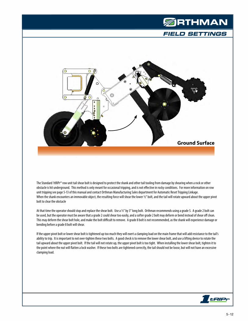
FIELD SETTINGS
Ground Surface
The Standard 1tRIPr® row unit tail shear bolt is designed to protect the shank and other tail tooling from damage by shearing when a rock or other obstacle is hit underground. This method is only meant for occasional tripping, and is not effective in rocky conditions. For more information on row unit tripping see page 5-13 of this manual and contact Orthman Manufacturing Sales department for Automatic Reset Tripping Linkage.When the shank encounters an immovable object, the resulting force will shear the lower ½” bolt, and the tail will rotate upward about the upper pivot bolt to clear the obstacle
At that time the operator should stop and replace the shear bolt. Use a ½” by 3” long bolt. Orthman recommends using a grade 5. A grade 2 bolt can be used, but the operator must be aware that a grade 2 could shear too easily, and a softer grade 2 bolt may deform or bend instead of shear off clean. This may deform the shear bolt hole, and make the bolt difficult to remove. A grade 8 bolt is not recommended, as the shank will experience damage or bending before a grade 8 bolt will shear.
If the upper pivot bolt or lower shear bolt is tightened up too much they will exert a clamping load on the main frame that will add resistance to the tail’s ability to trip. It is important to not over-tighten these two bolts. A good check is to remove the lower shear bolt, and use a lifting device to rotate the tail upward about the upper pivot bolt. If the tail will not rotate up, the upper pivot bolt is too tight. When installing the lower shear bolt, tighten it to the point where the nut will flatten a lock washer. If these two bolts are tightened correctly, the tail should not be loose, but will not have an excessive clamping load.
5 - 12

FIELD SETTINGS
Top HolesTube Retainer
Ground Surface
9 Inches 8 Inches
4 Inches
Ground Surface
ADJUSTABLE LIQUID TUBESIf you choose to apply NH3 or liquid fertilizer, or dry fertilizer it is advisable to consult documented information regarding safe handling and application of NH3 or liquid fertilizer. Refer to recognized sources. (pg. 2 - 9)
The Orthman 1tRIPr® Mole Shank Assembly can be used to place fertilizer at 2 different depths simultane-ously, and depending on your fertilizer setup could be used to apply 2 different rates of fertilizer in the strip at precisely 2 different depths.
The lowest setting is 1” above the deepest part of the mole point. The holes in the side plate are arranged in 1” increments vertically. This will help you calculate at what depth you are applying fertilizer. For example: If you have your shank set to till at a depth of 9”, the fertilizer tubes shown in the image below would be applying fertilizer at depths of 8” and 4”. The top holes are used to retain the liquid fertilizer tube or tubes. Use the innermost hole for retention if you are only utilizing one fertilizer tube, and use the outermost hole for retention if you are utilizing dual fertilizer tubes.
The example shown is the current factory setting from Orthman Manufacturing, and is only recommended as a starting point for the user. Your specific soil conditions, fertilizer placement points and fertilizer amounts will vary due to your own agronomic requirements.
The tops of the fertilizer tubes may need to be bent or formed at the top for better fit up to the end user’s fertilizer hose routing and hose clamps. Use caution when forming fertilizer tubes as to not kink the tube.
NOTE: The example shown is just one possible setting. Your specific soil condi-tions, fertilizer placement points and fertilizer amounts will vary due to your own agronomic requirements.
NOTE: If applying two different types of fertilizer, like NH3 through one tube and liquid fertilizer through the other tube it is the responsibility of the user to ad-equately insulate, or add additional space between the tubes in order that the NH3 does not freeze the liquid fertilizer tube.
DANGER
5 - 13
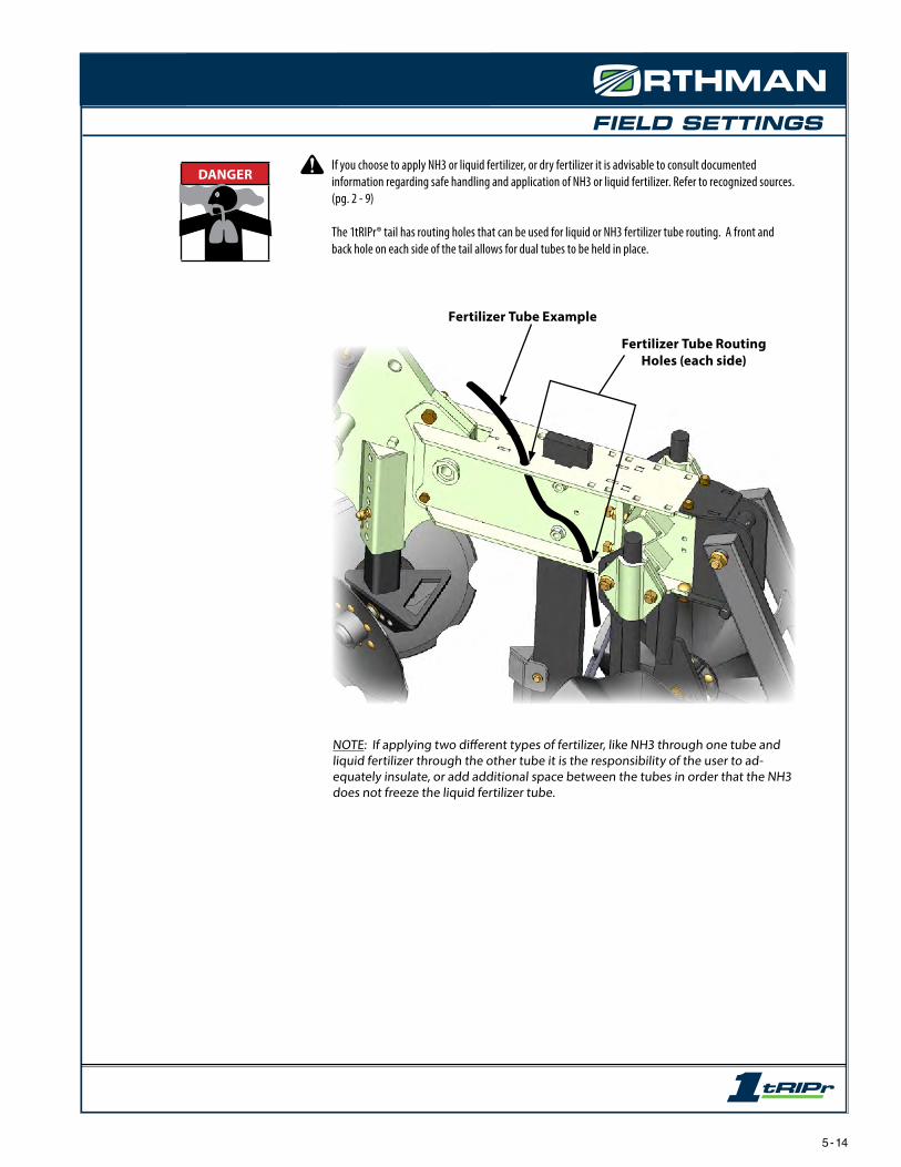
FIELD SETTINGS
If you choose to apply NH3 or liquid fertilizer, or dry fertilizer it is advisable to consult documented information regarding safe handling and application of NH3 or liquid fertilizer. Refer to recognized sources. (pg. 2 - 9)
The 1tRIPr® tail has routing holes that can be used for liquid or NH3 fertilizer tube routing. A front and back hole on each side of the tail allows for dual tubes to be held in place.
NOTE: If applying two different types of fertilizer, like NH3 through one tube and liquid fertilizer through the other tube it is the responsibility of the user to ad-equately insulate, or add additional space between the tubes in order that the NH3 does not freeze the liquid fertilizer tube.
Fertilizer Tube Example
Fertilizer Tube Routing Holes (each side)
DANGER
5 - 14
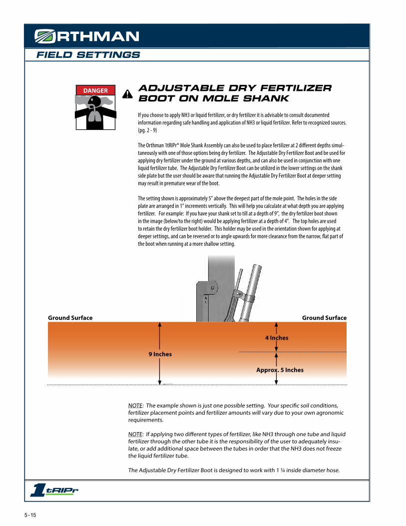
FIELD SETTINGS
Ground Surface
9 Inches
4 Inches
Ground Surface
ADJUSTABLE DRY FERTILIZER BOOT ON MOLE SHANK
If you choose to apply NH3 or liquid fertilizer, or dry fertilizer it is advisable to consult documented information regarding safe handling and application of NH3 or liquid fertilizer. Refer to recognized sources. (pg. 2 - 9)
The Orthman 1tRIPr® Mole Shank Assembly can also be used to place fertilizer at 2 different depths simul-taneously with one of those options being dry fertilizer. The Adjustable Dry Fertilizer Boot and be used for applying dry fertilizer under the ground at various depths, and can also be used in conjunction with one liquid fertilizer tube. The Adjustable Dry Fertilizer Boot can be utilized in the lower settings on the shank side plate but the user should be aware that running the Adjustable Dry Fertilizer Boot at deeper setting may result in premature wear of the boot.
The setting shown is approximately 5” above the deepest part of the mole point. The holes in the side plate are arranged in 1” increments vertically. This will help you calculate at what depth you are applying fertilizer. For example: If you have your shank set to till at a depth of 9”, the dry fertilizer boot shown in the image (below/to the right) would be applying fertilizer at a depth of 4”. The top holes are used to retain the dry fertilizer boot holder. This holder may be used in the orientation shown for applying at deeper settings, and can be reversed or to angle upwards for more clearance from the narrow, flat part of the boot when running at a more shallow setting.
NOTE: The example shown is just one possible setting. Your specific soil conditions, fertilizer placement points and fertilizer amounts will vary due to your own agronomic requirements.
NOTE: If applying two different types of fertilizer, like NH3 through one tube and liquid fertilizer through the other tube it is the responsibility of the user to adequately insu-late, or add additional space between the tubes in order that the NH3 does not freeze the liquid fertilizer tube.
The Adjustable Dry Fertilizer Boot is designed to work with 1 ¼ inside diameter hose.
Approx. 5 Inches
DANGER
5 - 15

FIELD SETTINGS
Ground Surface
9 Inches
5 Inches
Ground Surface
ADJUSTABLE DRY FERTILIZER BOOT ON DRY MOLE SHANK
If you choose to apply NH3 or liquid fertilizer, or dry fertilizer it is advisable to consult documented information regarding safe handling and application of NH3 or liquid fertilizer. Refer to recognized sources. (pg. 2 - 9)
The Orthman 1tRIPr® Dry Mole Shank Assembly can be used to place fertilizer at 3 different depths simul-taneously with one of those options being dry fertilizer. The Adjustable Dry Fertilizer Boot and be used for applying dry fertilizer under the ground at various depths, and can also be used in conjunction with one or two liquid fertilizer tubes. The Adjustable Dry Fertilizer Boot can be utilized in the lower settings on the shank side plate but the user should be aware that running the Adjustable Dry Fertilizer Boot at deeper setting will restrict the ability to run in conjunction with liquid or NH3 tubes.
The lowest liquid or NH3 setting is 1” above the deepest part of the mole point. The holes for adjusting these tubes are arranged in 1” increments vertically. This will help you calculate at what depth you are ap-plying fertilizer. For example: If you have your shank set to till at a depth of 9”, the fertilizer tubes shown in the image below would be applying fertilizer at depths of 8” and 4”. The adjustable dry boot is shown in the image below at a shallow setting. 1” incremental adjustment can be made by moving the dry boot holder up or down holes secured by a roll pin. Flipping the dry boot holder the opposite direction will give it the ability to reach deeper. The setscrew can be used for sub-inch adjustment.
NOTE: The example shown is just one possible setting. Your specific soil conditions, fertilizer placement points and fertilizer amounts will vary due to your own agronomic requirements.
NOTE: If applying two different types of fertilizer, like NH3 through one tube and liquid fertilizer through the other tube it is the responsibility of the user to adequately insu-late, or add additional space between the tubes in order that the NH3 does not freeze the liquid fertilizer tube.
The Adjustable Dry Fertilizer Boot is designed to work with 1 ¼ inside diameter hose.
DANGER
8 Inches
2 Inches
5 - 16

FIELD SETTINGS
If utilizing an Orthman Air Diffuser it can be orientated as shown in the picture below. The Air Diffuser can be mounted on either side of the row unit tail. The Air Diffuser is designed to work with an input hose size of 2” inside diameter. The output hose size is 1 ¼ inside diameter to match up with the Adjustable Dry Fertilizer Boot.
Orthman Diffuserand Diffuser Mount
5 - 17

FIELD SETTINGS
AUTOMATIC RESET LINKAGE
The Automatic Reset Linkage is engineered as a significant upgrade from a standard shear bolt for row unit and shank protection. When a rock or other obstacle is hit underground the row unit tail (that includes shank, wavy coulters and optional basket) can trip up and out of the ground. When the obstacle is passed over, four powerful reset springs, will drive the 1tRIPr® shank back into the ground, in most conditions. The Automatic Reset Linkage helps to protect valuable tooling from breaking and bending in rough and rocky soil conditions. The AR Linkage may help, but will not prevent damage from occasional glancing blows.
Ground Surface
Ground Surface
5 - 18

FIELD SETTINGS
The AR Linkage comes set from the factory to trip easily, and will need adjusted to adapt to your specific operating conditions. It is important that the user understand how the AR Linkage works and the results of the different adjustments. The image below identifies the important geometry points and adjustment locations. Without the AR Linkage, the tail would be free to rotate about point “D”. The Linkage installed keeps the tail from rotating about point “D” by creating a brace between points “A” and “B”. That brace is made of two links and has the ability to buckle in the middle at point “C”. When the shank encounters an immovable object, the resulting force will buckle the linkage at point “C” allowing the tail to rotate upward about point “D” un-til the obstacle is cleared. The upward rotation of the tail, and the buckling of the linkage causes the four reset springs to become stretched. The spring force stored in the stretched springs provides the power necessary to rotate the tail downward, which in turn drives the shank back into the ground and snaps the linkage back into place.
If you visualize a straight line between points “A” and point “B”, the distance point “C” is away from that straight line directly effects how difficult it is to buckle the trip linkage.The closer point “C” is to that line the more difficult it is to trip. The further away point “C” is from that line the easier it is to trip. Our factory setting from Orthman Mfg. puts this point “C” further from that line so it trips easily. Our factory setting (or distance “X” is ¾”) Operators are encouraged to adjust this setting by loosening the jam nut under point “C” and adjusting the set bolt. (with 15/16 wrenches) One full turn of this set bolt represents about 1/8”. It may only be necessary to move the set bolt ¼ to ½ a turn to achieve the correct offset distance for your soil and desired tripping operation.
5 - 19
Point ADistance “X”(Distance Point C is away from a straight line from A to B)
Point B
Point C
Sprint tensiondistance setting “Y”
Adjustable Screw for setting “X”
Point D
The preset tension in the four reset springs will affect two things. The amount of force available to drive the shank back into the ground from the tripped position, and the amount of force required to trip the linkage. A higher spring tension will increase both of these. The factory setting of the spring tension (or factory setting “Y”) is set to be 2”. This measurement may vary slightly due to differences in spring cut lengths and spring plug castings. This measure-ment is taken from the flat surface of the cast spring plug to the nearest flat surface of the ½” flat washer. To adjust the spring tension, loosen the jam nut that is up tight against the spring plug, and while holding the spring from rotating, screw in or out each of the four bolts equally, and then re-tighten the jam nut to prevent the springs from coming loose.

FIELD SETTINGS
SPRING SETTING “Y”factory 2” 1 7/8” 1 3/4” 1 5/8” 1 1/2”
SET S
CR
EW
SETTIN
GS
“X
” factory setting 3/4 2863 3181 3340 3817 3817
1/4 of a turn out 23/32 3181 3340 3658 3897 3897
1/2 of a turn out 11/16 3260 3578 3817 3976 3976
3/4 of a turn etc. 21/32 3340 3658 3976 4056 4135
5/8 3578 3897 4135 4374 4612
19/32 3817 3976 4374 4612 4771
9/16 3976 4056 4612 4771 4851
17/32 3976 4374 4771 4851 5248
1/2 3976 4771 4930 5407 5567
15/32 3976 4851 5407 5567 5885
7/16 3976 4851 5567 5646 6759
13/32 3976 4851 5964 6362 7157
3/8 3976 4851 6759 6998 7634
11/32 3976 4851 6998 7793 7952
5/16 3976 4851 7555 8032 8747
9/32 3976 4851 7714 8747 9622
screw removed 1/4 3976 4851 7952 9702 10338
This table has been created to help understand the effects that the set screw setting “X” and spring setting “Y” settings have on the AR Linkage’s ability to trip. The spring settings across the top represent different options for spring setting “Y”. Coordinate those with the numbers on the left of the chart that represent set screw setting “X”. The numbers shown in the chart represent the estimated amount of force (in pounds) that is required to trip the tail when the shank is at the deepest setting. For instance: With the factory set screw setting of ¾”, and the factory spring setting of 2” it will take approx. 2,850 pounds of force at the foot piece of the shank at its lowest setting to trip the row unit tail. As you can see, as the spring setting “Y” is de-creased (tightened up), and as the set screw setting “X” is decreased (unscrewed), the force required to trip is increased. This will make it more difficult for the row unit to trip when it encounters an obstacle.
Orthman Manufacturing encourages the operator to start out at this factory setting, where the row unit tail will most likely trip very easily. From that point you can adjust the set screw and the reset springs to attain the AR linkage setting that works well for you.
The standard version of the 1tRIPr® without the AR linkage is equipped with a shear bolt (pg. 5-11, 5-12). The amount of force it takes to shear this bolt is slightly over 8,000 lbs. Notice that the chart has values that exceed the 8,000 lb. mark. Orthman Manufacturing recommends using extreme caution when setting the AR Linkage to a setting above 8,000 lbs. Using a setting that exceeds the 8,000 lb. mark is likely to increase the chances of damaging the shank in the event an obstacle is encountered.
1 full turn out
2 full turns out
3 full turns out
5 - 20
see below
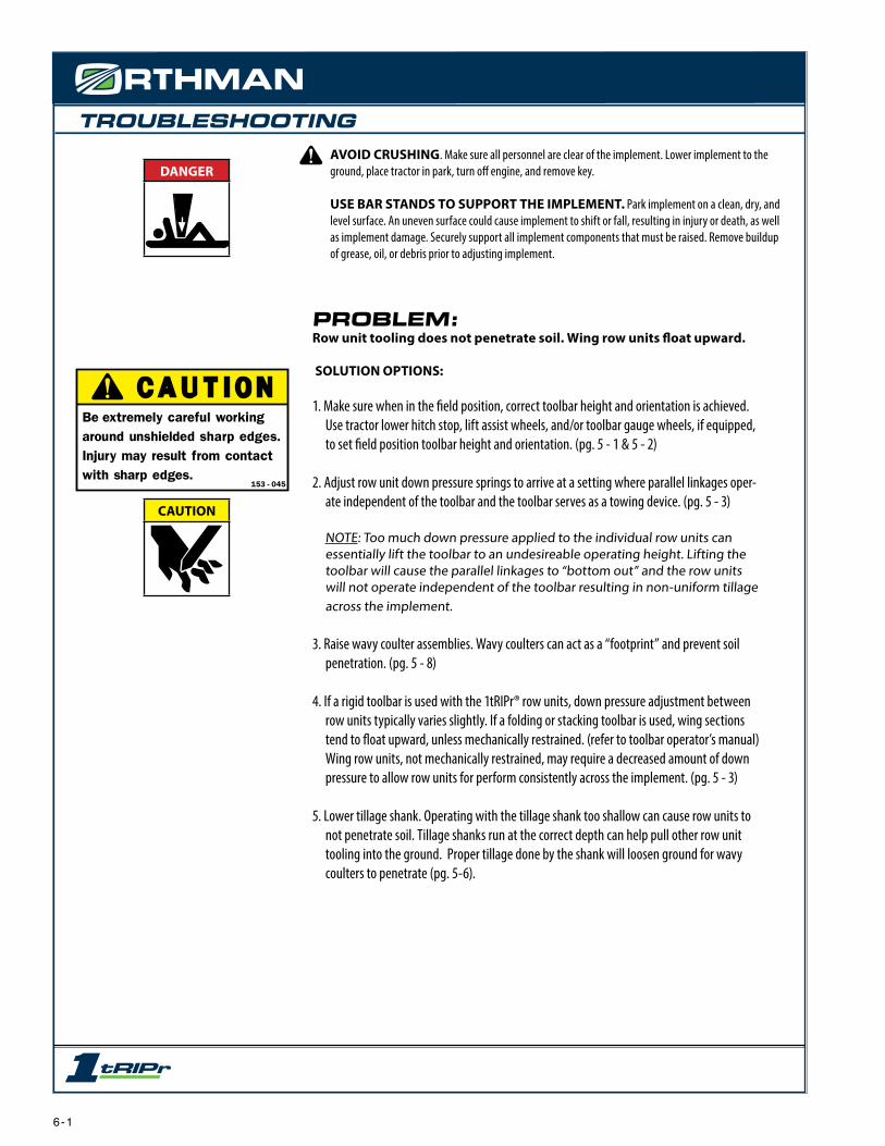
TROUBLESHOOTINGAVOID CRUSHING. Make sure all personnel are clear of the implement. Lower implement to the ground, place tractor in park, turn off engine, and remove key.
USE BAR STANDS TO SUPPORT THE IMPLEMENT. Park implement on a clean, dry, and level surface. An uneven surface could cause implement to shift or fall, resulting in injury or death, as well as implement damage. Securely support all implement components that must be raised. Remove buildup of grease, oil, or debris prior to adjusting implement.
DANGER
CAUTION
C A U T I O NBe extremely careful working around unshielded sharp edges. Injury may result from contact with sharp edges.
153 - 045
153-045.indd 1 1/12/2005 8:49:28 AM
PROBLEM:Row unit tooling does not penetrate soil. Wing row units float upward.
SOLUTION OPTIONS:
1. Make sure when in the field position, correct toolbar height and orientation is achieved. Use tractor lower hitch stop, lift assist wheels, and/or toolbar gauge wheels, if equipped, to set field position toolbar height and orientation. (pg. 5 - 1 & 5 - 2)
2. Adjust row unit down pressure springs to arrive at a setting where parallel linkages oper-ate independent of the toolbar and the toolbar serves as a towing device. (pg. 5 - 3)
NOTE: Too much down pressure applied to the individual row units can essentially lift the toolbar to an undesireable operating height. Lifting the toolbar will cause the parallel linkages to “bottom out” and the row units will not operate independent of the toolbar resulting in non-uniform tillage across the implement.
3. Raise wavy coulter assemblies. Wavy coulters can act as a “footprint” and prevent soil penetration. (pg. 5 - 8)
4. If a rigid toolbar is used with the 1tRIPr® row units, down pressure adjustment between row units typically varies slightly. If a folding or stacking toolbar is used, wing sections tend to float upward, unless mechanically restrained. (refer to toolbar operator’s manual) Wing row units, not mechanically restrained, may require a decreased amount of down pressure to allow row units for perform consistently across the implement. (pg. 5 - 3)
5. Lower tillage shank. Operating with the tillage shank too shallow can cause row units to not penetrate soil. Tillage shanks run at the correct depth can help pull other row unit tooling into the ground. Proper tillage done by the shank will loosen ground for wavy coulters to penetrate (pg. 5-6).
6 - 1

TROUBLESHOOTINGAVOID CRUSHING. Make sure all personnel are clear of the implement. Lower implement to the ground, place tractor in park, turn off engine, and remove key.
USE BAR STANDS TO SUPPORT THE IMPLEMENT. Park implement on a clean, dry, and level surface. An uneven surface could cause implement to shift or fall, resulting in injury or death, as well as implement damage. Securely support all implement components that must be raised. Remove buildup of grease, oil, or debris prior to adjusting implement.
DANGER
CAUTION
C A U T I O NBe extremely careful working around unshielded sharp edges. Injury may result from contact with sharp edges.
153 - 045
153-045.indd 1 1/12/2005 8:49:28 AM
PROBLEM:Row unit plugs with field residue between the depth band coulter assem-bly and trash opener assembly.
SOLUTION OPTIONS:
1. Proper toolbar height and orientation setting should ensure maximum depth band coulter cutting depth. Make sure the coulter is penetrating soil in order that the depth band governs soil penetration (pg. 5 - 1 & 5 - 2).
2. Wet or damp field conditions can adversely affect the performance of the 1tRIPr® row unit. Typically, wet or damp field conditions do not allow residue to pass through the row unit as effectively as drier conditions.
3. Alter ground speed to change rate at which field residue passes through row unit tooling. Slower ground speeds generally reduce plugging by allowing residue to smoothly pass through row unit tooling.
4. Slightly raise row cleaner assembly to reduce residue in contact with the trash opener assembly (pg. 5 - 4).
5. Remove and store row cleaner assembly (pg. 5 - 4).
6. Adjust row cleaner width (pg. 5-5).
7. Adjust row cleaner distance fore and aft (pg. 5-5).
6 - 2

TROUBLESHOOTINGAVOID CRUSHING. Make sure all personnel are clear of the implement. Lower implement to the ground, place tractor in park, turn off engine, and remove key.
USE BAR STANDS TO SUPPORT THE IMPLEMENT. Park implement on a clean, dry, and level surface. An uneven surface could cause implement to shift or fall, resulting in injury or death, as well as implement damage. Securely support all implement components that must be raised. Remove buildup of grease, oil, or debris prior to adjusting implement.
DANGER
CAUTION
C A U T I O NBe extremely careful working around unshielded sharp edges. Injury may result from contact with sharp edges.
153 - 045
153-045.indd 1 1/12/2005 8:49:28 AM
PROBLEM:Row unit plugs with field residue between the trash opener assembly and tillage shank.
SOLUTION OPTIONS:
1. Slightly lower row cleaner assembly to reduce the amount of field residue in front of the tillage shank. (pg. 5 - 4)
2. Proper toolbar height and orientation setting should ensure maximum depth band coulter cutting depth. Make sure the coulter is penetrating soil in order that the depth band governs soil penetration. (pg. 5 - 1 & 5 - 2)
3. Alter ground speed to change rate at which field residue passes through row unit tooling. Slower ground speeds generally reduce plugging by allowing residue to smoothly pass through row unit tooling.
4. Wet or damp field conditions can adversely effect the performance of the 1tRIPr® row unit. Typically, wet or damp field conditions do not allow residue to pass through the row unit as effectively as drier conditions.
6. Adjust row cleaner width (pg. 5-5).
7. Adjust row cleaner distance fore and aft (pg. 5-5).
6 - 3

TROUBLESHOOTINGAVOID CRUSHING. Make sure all personnel are clear of the implement. Lower implement to the ground, place tractor in park, turn off engine, and remove key.
USE BAR STANDS TO SUPPORT THE IMPLEMENT. Park implement on a clean, dry, and level surface. An uneven surface could cause implement to shift or fall, resulting in injury or death, as well as implement damage. Securely support all implement components that must be raised. Remove buildup of grease, oil, or debris prior to adjusting implement.
DANGER
CAUTION
C A U T I O NBe extremely careful working around unshielded sharp edges. Injury may result from contact with sharp edges.
153 - 045
153-045.indd 1 1/12/2005 8:49:28 AM
PROBLEM:Row unit plugs with field residue between the tillage shank and wavy coulters.
SOLUTION OPTIONS:
1. Slightly increase wavy coulter tillage width. Increasing tillage width should allow residue to pass between the wavy coulters (pg. 5 - 8).
NOTE: It is not recommended for wavy coulter tillage width to exceed the width at which trash openers remove residue. If wavy coulter tillage zone exceeds the residue free strip, wavy coulters are more likely to plug as well as not penetrate soil.
2. Increase distance between tillage shank assembly and wavy coulter assemblies by adjust-ing wavy coulter assemblies fore and aft (pg. 5 - 9).
NOTE: Increasing distance relationship between row unit tooling usually increases the ability of field residue to pass through the row unit without plugging.
3. Alter ground speed to change rate at which field residue passes through row unit tooling. Slower ground speeds generally reduce plugging by allowing residue to smoothly pass through row unit tooling.
4. Wet or damp field conditions can adversely effect the performance of the 1tRIPr® row unit. Typically, wet or damp field conditions do not allow residue to pass through the row unit as effectively as drier conditions.
6 - 4

TROUBLESHOOTINGAVOID CRUSHING. Make sure all personnel are clear of the implement. Lower implement to the ground, place tractor in park, turn off engine, and remove key.
USE BAR STANDS TO SUPPORT THE IMPLEMENT. Park implement on a clean, dry, and level surface. An uneven surface could cause implement to shift or fall, resulting in injury or death, as well as implement damage. Securely support all implement components that must be raised. Remove buildup of grease, oil, or debris prior to adjusting implement.
DANGER
CAUTION
C A U T I O NBe extremely careful working around unshielded sharp edges. Injury may result from contact with sharp edges.
153 - 045
153-045.indd 1 1/12/2005 8:49:28 AM
PROBLEM:Field residue plugs between row units.
SOLUTION OPTIONS:
1. Slightly raise row cleaner assembly to reduce the amount of field residue passing between row units (pg. 5 - 4).
2. Alter ground speed to change rate at which field residue passes through row unit tooling. Slower ground speeds generally reduce plugging by allowing residue to smoothly pass through row unit tooling.
3. Decrease wavy coulter tillage width. Decreasing tillage width should allow more clearance between row units (pg. 5 - 8).
4. Increase distance between tillage shank assembly and wavy coulter assemblies by adjust-ing wavy coulter assemblies fore and aft (pg. 5 - 9).
NOTE: Increasing distance relationship between row unit tooling usually increases the ability of field residue to pass through the row unit without plugging.
5. Wet or damp field conditions can adversely effect the performance of the 1tRIPr® row unit. Typically, wet or damp field conditions do not allow residue to pass through the row unit as effectively as drier conditions.
6. Adjust row cleaner width (pg. 5-5).
7. Adjust row cleaner distance fore and aft (pg. 5-5).
6 - 5

TROUBLESHOOTINGAVOID CRUSHING. Make sure all personnel are clear of the implement. Lower implement to the ground, place tractor in park, turn off engine, and remove key.
USE BAR STANDS TO SUPPORT THE IMPLEMENT. Park implement on a clean, dry, and level surface. An uneven surface could cause implement to shift or fall, resulting in injury or death, as well as implement damage. Securely support all implement components that must be raised. Remove buildup of grease, oil, or debris prior to adjusting implement.
DANGER
CAUTION
C A U T I O NBe extremely careful working around unshielded sharp edges. Injury may result from contact with sharp edges.
153 - 045
153-045.indd 1 1/12/2005 8:49:28 AM
PROBLEM:Row unit does not trip or trips too easily.Shear bolt will not shear or shears too easily.
SOLUTION OPTIONS:
1. Row unit does not trip or trips too easily. A. Check to see it tipping mechanism is installed correctly (pg. 4 - 16 to 4-20). B. Reference field settings on (pg. 5 - 18 to 5 - 20).
2. Shear bolt will not shear or shears too easily. A. Reference field settings on (pg. 5 - 11 to 5 - 12).
6 - 6

MAINTENANCE
PRACTICE SAFE MAINTENANCE
Proper maintenance is your responsibility. Maintenance neglect and/or poor maintenance practices can result in injury or death. Always use the proper tools to maintain implement.
AVOID CRUSHING. Make sure all personnel are clear of the implement.Lower implement to the ground, place tractor in park, turn off engine, and remove key.
USE BAR STANDS AND CYLINDER STOPS TO SUPPORT THE IMPLEMENT. Park implement on a clean, dry, and level surface. An uneven surface could cause implement to shift or fall, resulting in injury or death, as well as implement damage. Securely support all implement components that must be raised. Remove buildup of grease, oil, or debris prior to maintaining implement.
AVOID ENTANGLEMENT. Never lubricate or service implement in motion. Keep away from power driven parts when in motion. Disengage power sources prior to maintain-ing implement. Injury or death can result from contact with power driven parts when in motion.
AVOID CRUSHING. Do not stand between the tractor and implement when connect-ing or disconnecting implement. Injury or death can result from being trapped between the tractor and implement.
Escaping pressurized hydraulic fluid can penetrate skin, resulting in injury or death. Relieve hydraulic system pressure before connecting or disconnecting tractor. Use cardboard or wood, NOT BODY PARTS, to check for suspected hydraulic leaks. Wear protective gloves and safety glasses or goggles when working with hydraulic systems. If an accident occurs, see a doctor immediately for proper treatment.
DANGER
DANGER
DANGER
DANGER
WARNING
off
7 - 1

MAINTENANCE
7 - 2
TORQUE SPECIFICATIONSUnified Inch Bolt and Screw Torque Values
Bolt or Screw
Size
SAE Grade 1 SAE Grade 2a SAE Grade 5, 5.1 or 5.2 SAE Grade 8 or 8.2
Lubricatedb Dryc Lubricatedb Dryc Lubricatedb Dryc Lubricatedb Dryc
N•m lb-in N•m lb-in N•m lb-in N•m lb-in N•m lb-in N•m lb-in N•m lb-in N•m lb-in
1/4 3.7 33 4.7 42 6 53 7.5 66 9.5 84 12 106 13.5 120 17 150
N•m lb-ft N•m lb-ft
5/16 7.7 68 9.8 86 12 106 15.5 137 19.5 172 25 221 28 20.5 35 26
N•m lb-ft N•m lb-ft
3/8 13.5 120 17.5 155 22 194 27 240 35 26 44 32.5 49 36 63 46
N•m lb-ft N•m lb-ft N•m lb-ft
7/16 22 194 28 20.5 35 26 44 32.5 56 41 70 52 80 59 100 74
N•m lb-ft
1/2 34 25 42 31 53 39 67 49 85 63 110 80 120 88 155 115
9/16 48 35.5 60 45 76 56 95 70 125 92 155 115 175 130 220 165
5/8 67 49 85 63 105 77 135 100 170 125 215 160 240 175 308 225
3/4 120 88 150 110 190 140 240 175 300 220 380 280 425 315 540 400
7/8 190 140 240 175 190 140 240 175 490 360 615 455 690 510 870 640
1 285 210 360 265 285 210 360 265 730 540 920 680 1030 760 1300 960
1-1/8 400 300 510 375 400 300 510 375 910 670 1150 850 1450 1075 1850 1350
1-1/4 570 420 725 535 570 420 725 535 1280 945 1630 1200 2050 1500 2600 1920
1-3/8 750 550 950 700 750 550 950 700 1700 1250 2140 1580 2700 2000 3400 2500
1-1/2 990 730 1250 930 990 730 1250 930 2250 1650 2850 2100 3600 2650 4550 3350
Torque values listed are for general use only, based on the strength of the bolt or screw. DO NOT use these values if a different torque value or tightening procedure is given for a specific application. For plastic insert or crimped steel type lock nuts, for stainless steel fasteners, or for nuts on U-bolts, see the tightening instructions for the specific application. Shear bolts are designed to fail under predetermined loads. Always replace shear bolts with identical grade.
Replace fasteners with the same or higher grade. If higher grade fasteners are used, tighten these to the strength of the original. Make sure fastener threads are clean and that you properly start thread engagement. When possible, lubricate plain or zinc plated fasteners other than lock nuts, wheel bolts or wheel nuts, unless different instructions are given for the specific application.
a Grade 2 applies for hex cap screws (not hex bolts) up to 6. in (152 mm) long. Grade 1 applies for hex cap screws over 6 in. (152 mm) long, and for all other types of bolts and screws of any length.b “Lubricated” means coated with a lubricant such as engine oil, fasteners with phosphate and oil coatings, or 7/8 in. and larger fasteners with JDM F13C zinc flake coating.
c “Dry” means plain or zinc plated without any lubrication, or 1/4 to 3/4 in. fasteners with JDM F13B zinc flake coating.
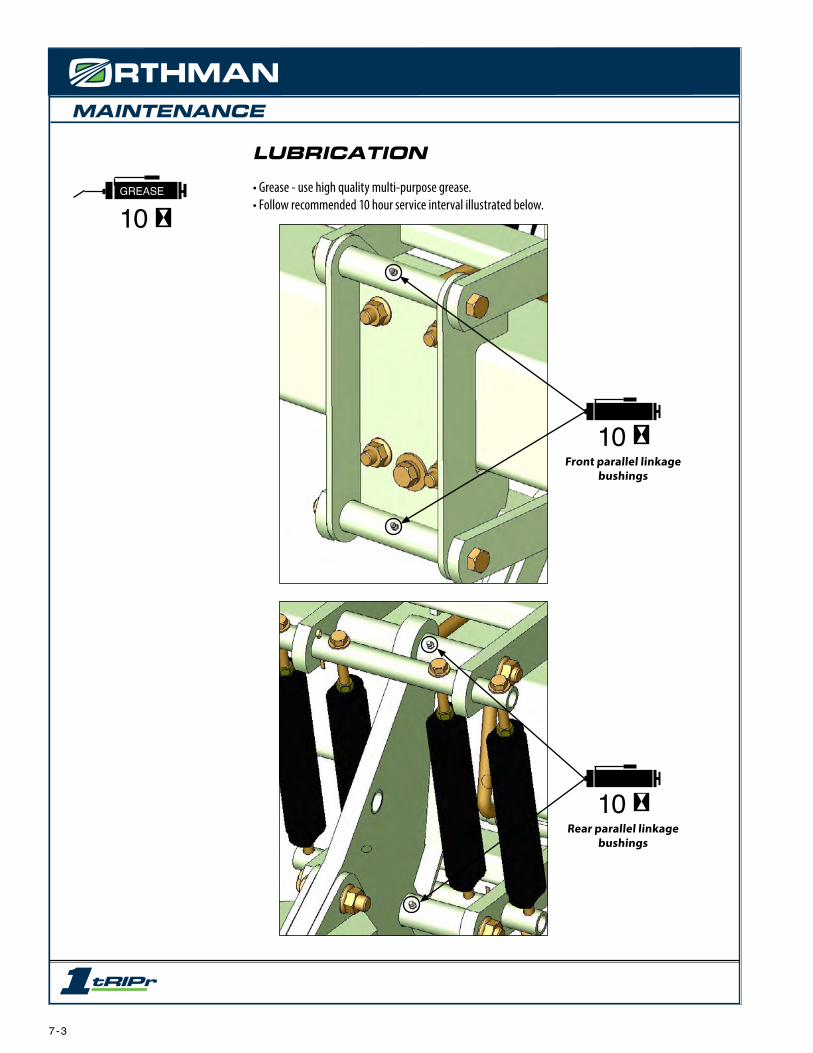
MAINTENANCE
7 - 3
LUBRICATION
• Grease - use high quality multi-purpose grease. • Follow recommended 10 hour service interval illustrated below.
GREASE
10
10Front parallel linkage
bushings
10Rear parallel linkage
bushings
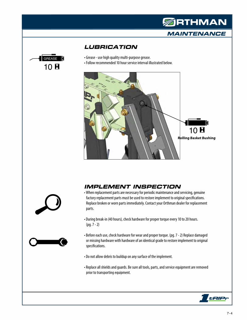
MAINTENANCE
7 - 4
LUBRICATION
• Grease - use high quality multi-purpose grease. • Follow recommended 10 hour service interval illustrated below.
GREASE
10
10Rolling Basket Bushing
IMPLEMENT INSPECTION• When replacement parts are necessary for periodic maintenance and servicing, genuine
factory replacement parts must be used to restore implement to original specifications. Replace broken or worn parts immediately. Contact your Orthman dealer for replacement parts.
• During break-in (40 hours), check hardware for proper torque every 10 to 20 hours. (pg. 7 - 2)
• Before each use, check hardware for wear and proper torque. (pg. 7 - 2) Replace damaged or missing hardware with hardware of an identical grade to restore implement to original specifications.
• Do not allow debris to buildup on any surface of the implement.
• Replace all shields and guards. Be sure all tools, parts, and service equipment are removed prior to transporting equipment.

MAINTENANCE
IMPLEMENT STORAGE
• Clean and touch up paint seasonally to avoid corrosion and rust. Contact your Orthman dealer for touch up paint.
• Inspect all safety and Orthman decals and replace if missing or damaged. Contact your Orthman dealer for replacement decals. (pg. 2 - 10, 2 - 11)
• Grease all zerks regardless of hourly interval prior to storage. (pg. 7 - 3, 7 - 4)
• Check all hardware according to torque specifications prior to storage. (pg. 7 - 2)
• Replace all worn or damaged parts prior to storage.
• Store inside if possible. Storing implement inside will prolong the life of the components.
AVOID CRUSHING. Make sure all personnel are clear of the implement. Lower implement to the ground, place tractor in park, turn off engine, and remove key.
Storing implement on the ground will relieve the tractor three point hitch of hydraulic pres-sure.Hydraulic systems tend to settle, endangering anything underneath the implement.
USE BAR STANDS TO SUPPORT THE IMPLEMENT. Store implement on a clean, dry, and level surface. An uneven surface could cause implement to shift or fall, resulting in injury or death, as well as implement damage. Securely support all implement components that must be raised. Store implement away from human activity.
DANGER
WARNING
off
7 - 5

NOTES
7 - 6

PARTS IDENTIFICATION
2
34
5
1
67
8
8
8
8
9
10
11
12
14
14
13
15 16
17
18
1819
20
2122
23
24
25
8 - 1
MAIN FRAME AND TAIL ASSEMBLYKey Part # Description Qty Notes Key Part # Description Qty Notes
1 385-854 Scraper Assembly 1 Includes items #2 thru 5 14 100-122 Bolt 1 1/2” x 3”, Grade 5
2 100-003 Carriage bolt 2 5/16” x 1”, Grade 5 15 108-020 Lock washer 1 1/2”
3 108-006 Flat washer 2 5/16” 16 102-007 Nut 1 1/2”
4 108-017 Lock washer 2 5/16” 17 106-160 Set screw 2 5/8” x 2 1/2”, Square head
5 102-004 Nut 2 5/16” 18 102-016 Jam nut 6 5/18”
6 100-274 Bolt 1 3/4” x 9 1/2”, Grade 8 19 106-149 Set screw 4 5/8” x 1 1/2”, Square head
7 387-150 Main Frame 1 Includes #8 thru 11 20 100-031 Carriage bolt 4 5/8” x 1 3/4”, Grade 5
8 134-067 Bushing 4 1 1/4” x 1” x 2 1/2” split 21 387-115 Cross Tube 2 ---
9 110-001 Grease fitting 2 1/4” Straight 22 313-293 Cap 2 ---
10 134-017 Bushing 1 1 3/4” x 1 1/2” x 1” split 23 102-108 Flanged nut 2 3/4”
11 134-034 Bushing 1 1 1/4” x 1” x 1” split 24 102-029 Lock nut 2 5/8”
12 100-160 Bolt 1 3/4” x 3”, Grade 5 25 387-100 Tail 1 ---
13 102-121 Flanged nut 2 3/4” x 3”, Grade 5

PARTS IDENTIFICATION
1514
14
1613
11
10
13 11
12
1
1
1
1
2
2
2
2
3
3
3
3
4
44
4
4
19
20
7
17
18
18
6
5
8
9
21
22
MOUNT AND PARALLEL LINKAGE ASSEMBLYKey Part # Description Qty Notes Key Part # Description Qty Notes
1 100-176 Bolt 4 3/4” x 10 1/2”, Grade 8 12 100-288 Bolt 4 1/2” x 3 1/2” Full thread, Grade 5
2 385-140 Bushing 4 1”OD x 3/4”ID x 8” 13 102-007 Nut 8 1/2”
3 134-067 Bushing 8 1” x 1 1/4” x 2 1/2”, Split 14 340-029 Spring Plug 8 ---
4 102-121 Lock nut 9 3/4” Serrated flange 15 317-925 Spring 4 2”OD x 10” spring
5 110-001 Grease fitting 3 1/4”-28, straight 16 311-401 Spring Assembly 4 Includes items #14 & 15
6 387-525 Wedge Mount 1 Includes items #3 & 5 17 104-030 Cotter pin 4 3/16” x 2”
7 315-031 U-bolt 2 3/4”, For 7” x 7” bar 18 387-310 Trunion Tube 2 Upper and Lower (13 3/8 long)
8 387-521 Wedge 1 Tapped and Plated 19 385-095 Parallel Linkage 1 Lower
9 100-490 Bolt 1 3/4” x 4” Full Thread, Grade 5 20 385-093 Parallel Linkage 1 Upper
10 100-124 Bolt 4 1/2” x 3 1/4”, Grade 5 21 108-022 Lock washer 1 3/4”
11 108-001 Flat washer 8 1/2” SAE 22 108-011 Flat washer 1 3/4”
8 - 2

PARTS IDENTIFICATION
1
3
4
3
5
6
5
78
2
DEPTH BAND COULTER ASSEMBLYKey Part # Description Qty. Notes
1 100-118 Bolt 4 1/2” x 2”, Grade 5
2 385-950 Hub assembly 1 4 bolt, 3/4 bolt hub Includes items # 3 and 4
3 120-041 Bearing 2 3/4” ID x 1.8505 OD bearing
4 385-945 Spacer 1 1 1/4 OD x .813 ID x 5.768 long
5 385-167 Depth Band 2 15 1/4” Diameter, conical
6 166-033 Disc 1 22” Smooth
7 312-131 Plate 1 Depth band reinforcing plate
8 102-119 Lock nut 4 1/2”, Smooth flange
- 385-493 Depth Band Assembly 1 Includes Items #1 thru 8
8 - 3
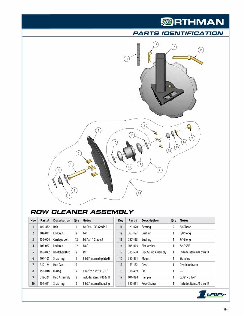
PARTS IDENTIFICATION
1
3
5
10
1111
10
4
1213
142
8
7
6
15
17
16
9
18
19
ROW CLEANER ASSEMBLYKey Part # Description Qty Notes Key Part # Description Qty Notes
1 100-472 Bolt 2 3/4” x 4 1/4”, Grade 5 11 120-070 Bearing 2 3/4” bore
2 102-031 Lock nut 2 3/4” 12 387-127 Bushing 1 5/8” long
3 100-004 Carriage bolt 12 3/8” x 1”, Grade 5 13 387-128 Bushing 1 7/16 long
4 102-027 Lock nut 12 3/8” 14 108-003 Flat washer 1 3/4” SAE
5 166-042 Knotched Disc 2 16” 15 385-590 Disc & Hub Assembly 1 Includes items #1 thru 14
6 104-105 Snap ring 2 2 3/8” Internal (plated) 16 385-831 Mount 1 Standard
7 319-126 Hub Cap 2 --- 17 153-152 Decal 1 Depth indicator
8 150-018 O-ring 2 2 1/2” x 2 3/8” x 3/16” 18 313-469 Pin 1 ---
9 312-321 Hub Assembly 2 Includes items #10 & 11 19 104-094 Hair pin 1 5/32” x 3 1/4”
10 104-061 Snap ring 2 2 3/8” Internal housing - 387-051 Row Cleaner 1 Includes Items #1 thru 17
8 - 4

PARTS IDENTIFICATION
MOLE SHANK ASSEMBLYKey Part # Description Qty Notes Key Part # Description Qty Notes
1 387-130 Shank 1 1” x 4” Mole Shank 6 385-552 Chemical Tube 2 ---
2 164-057 Mole Point 1 1 1/16” Wide Footpiece 7 387-060 Mole Shank 1 Includes Items #1 thru 6
3 104-008 Roll pin 1 5/16” x 1 3/4” Spiral 8 387-135 Dry Boot 1 Stainless Steel
4 104-117 Roll pin 4 5/16” x 1” Spiral 9 387-138 Boot Holder 1 Stainless Steel
5 153-152 Decal 1 Depth Indicator 10 635-016 Dry Boot Package 1 Includes Items #4, 8 & 9
1
2
3
444
4
5
6
6
4
4
9
10
7
8
8 - 5

PARTS IDENTIFICATION
DRY MOLE SHANK ASSEMBLYKey Part # Description Qty Notes Key Part # Description Qty Notes
1 387-200 Shank 1 1” x 4” Dry Mole Shank 8 387-209 Dry Boot 1 Stainless Steel
2 164-057 Mole Point 1 1 1/16” Wide Footpiece 9 387-206 Holder 1 Dry Boot Holder
3 387-205 Wear Plate 1 Right 10 104-246 Roll pin 2 5/16” x 3/4” Spiral
4 387-204 Wear Plate 1 Left 11 153-152 Decal 1 Depth Indicator
5 385-522 Chemical Tube 2 --- 12 106-190 Screw 6 Flat Socket Head 3/8” x 3/4”
6 104-039 Roll pin 3 5/16” x 1 3/4” Spiral 13 104-221 Roll pin 1 5/16” x 2” Spiral
7 106-091 Set screw 1 SQ. head 1/4-20 x 1” 14 387-059 Dry Mole Shank - Full Assembly
2
1
11
79
8
5
5
12
3
610
10
6
6
4
6
13
14
8 - 6

PARTS IDENTIFICATION
SHALLOW TILLAGE ASSEMBLYKey Part # Description Qty Notes Key Part # Description Qty Notes
1387-251 Shank 1 1” x 4” 9 100-202 Bolt 1 3/4” x 3 3/4”, Grade 5
387-028 Shank 1 1” x 3” 10 120-070 Bearing 1 3/4” bore
2 387-034 Hub Assembly 2 Includes Items #5 thru 14 11 100-043 Carriage bolt 4 1/2” x 1”, Grade 5
3 320766 Wavy Coulter 2 18” (13 waves) 4 bolt 12 312-057 Spacer 1 1/2”
4 153-152 Decal 1 Depth Indicator 13 108-022 Lock washer 1 3/4”
5 104-105 Snap ring 3 2 3/8” Internal, Plated 14 102-009 Nut 1 3/4”
6 319-126 Hub Cap 1 --- 15 387-250 Complete Assembly 1 1” x 4” shank
7 150-018 O-Ring 2 2 1/2” OD x 2 1/8” ID 16 387-029 Complete Assembly 1 1” x 3” shank
8 102-028 Lock nut 4 1/2”
1
3
9
8
6
2
5
5
10
10
5
11
12
1413
2
3
7
4
15
FULL ASSEMBLIES
16
8 - 7

PARTS IDENTIFICATION
MOLE KNIFE & NH3 KNIFE ASSEMBLIESKey Part # Description Qty Notes Key Part # Description Qty Notes
1 100-121 Bolt 2 1/2” x 2 3/4”, Grade 5 9 317-301 Adaptor plate 1 Left
2 108-020 Lock washer 4 1/2” 10 317-212 Adaptor plate 1 Right
3 102-007 Nut 4 1/2” 11 104-117 Roll pin 2 5/16”
4 100-119 Bolt 2 1/2” x 2 1/4”, Grade 5 12 385-577 Mole Knife 1 B-33 Fertilizer Mole Knife
5 310-012 Clamp Package 1 Includes Items # 1-4 and 9-10 13 176-003 Knife 1 NH3
6 311-047 Shank 1 1” x 4” 14 635-014 Mole Knife Package - Complete Assembly
7 153-152 Decal 1 Depth Indicator 15 635-017 NH3 Knife Package - Compete Assembly
8 385-552 Chemical Tube 1 ---
13
12
1
1
4
4
3
2109
5
6
7
11
8
1514
8 - 8

PARTS IDENTIFICATION
1
2
3
4
56
7
89
11
11
12
12
13
14
15
10
16
WAVY COULTER ASSEMBLYKey Part # Description Qty Notes Key Part # Description Qty Notes
1 100-004 Carriage bolt 6 3/8” x 1”, Grade 5 9 102-009 Nut 1 3/4”, Grade 5
2 102-027 Lock nut 6 3/8” 10 312-319 Hub Assembly 1 Includes items #11 & 12
3 166-040 Wavy Coulter 1 17 1/2” 11 104-061 Snap ring 2 2 3/8” Internal housing
4 104-105 Snap Ring 1 2 3/8” Internal (plated) 12 120-164 Bearing 2 3/4” bore
5 319-126 Hub Cap 1 --- 13 312-057 Spacer 1 ---
6 150-018 O-ring 1 2 1/2” x 2 3/8” x 3/16” 14 312-096 Shank 1 Right Side (longer shank 23” shaft)
7 100-202 Bolt 1 3/4” x 3 3/4”, Grade 5 15 312-097 Shank 1 Left Side (shorter shank 19” shaft)
8 108-022 Lock washer 1 3/4” 16 385-545 Hub & Disc Assy. - Includes items #1 thru 13
8 - 9

PARTS IDENTIFICATION
19
18
20
17
16
1423
22
21
1
2
3
4
4
4
5
5
5
6
7
8
9
10
11
11
13
15
24
2425
2612
28
28
29
30
27
TRIP LINKAGE ASSEMBLYKey Part # Description Qty Notes Key Part # Description Qty Notes
1 385-808 Bottom linkage 1 --- 16 104-039 Roll pin 1 5/16” x 1 1/4” Spiral
2 100-602 Bolt 1 5/8” Fine thread x 1 1/2” Full thread 17 385-843 Sleeve 1 ---
3 102-163 Jam nut 1 5/8” Fine thread 18 340-029 Plug 1 ---
4 100-323 Bolt 3 3/4” x 3 1/2”, Grade 8 19 317-921 Spring 1 ---
5 102-031 Lock nut 3 3/4” 20 317-920 Spring & Plug 4 Includes Items #18 & 19
6 100-187 Bolt 1 1” x 5”, Grade 5 21 102-015 Jam nut 4 1/2”
7 102-020 Lock nut 1 1” Nylock, Grade 2 22 108-001 Flat washer 4 1/2”
8 100-012 Carriage bolt 8 1/2” x 1 1/4”, Grade 5 23 100-288 Bolt 4 1/2” x 3 1/2”, Grade 5
9 102-028 Lock nut 8 1/2” 24 387-085 Crush Sleeve 2 .995 OD x .760 ID x 1.469 long
10 387-082 Mount 1 Includes Item #11 25 387-084 Crush Sleeve 1 .995 OD x .760 ID x 1.188 long
11 134-111 Bushing 2 1 1/4” OD x 1” ID x 1 1/4” long 26 387-086 Crush Sleeve 1 1.495 OD x 1.005 ID x 1.038 long
12 387-150 Main Frame 1 Includes Items #27 thru 30 27 134-017 Bushing 1 1 3/4 OD x 1 1/2 ID x 1” long
13 387-080 Top linkage 1 Includes Item #11 28 134-067 Bushing 4 1 1/4” OD x 1” ID x 2 1/2” long
14 385-829 Pin 1 --- 29 110-001 Grease Zerk 2 1/4” Straight
15 387-100 Tail 1 --- 30 134-034 Bushing 1 1 1/4” OD x 1” ID x 1” long
8 - 10

PARTS IDENTIFICATION
1
2
3
4
5
6
7
8
9
10
11
12
13
14
1516
17
18
10
19
2021
22
2323
24
25
26
ROLLING BASKET ASSEMBLYKey Part # Description Qty Notes Key Part # Description Qty Notes
1
327-201
Basket Frame 1
Standard frame for 14” W basket 12 100-058 Carriage bolt 4 1/2” x 1 1/2”, Grade 5
13 100-226 Bolt 1 1/2” x 5”, Grade 5
327-211 Narrow basket frame for 8” W basket 14 108-001 Flat washer 1 1/2” SAE
2
327-050
Basket 1
Standard 14” W basket with flat bars 15 327-205 Spring 1 Includes Items #16-17
16 340-029 Plug 1 Spring Drilled
327-178 8” W basket with flat bars (for narrow rows) 17 327-206 Spring 3 .362 Wire
327-171 14” W basket with berm promoting (curved) cleats 18 120-010 Bearing 2 1” bore
3 100-289 Bolt 1 3/4” x 10”, Grade 8 19 100-003 Carriage bolt 6 5/16” x 1”, Grade 5
4 102-121 Flange nut 1 3/4” locking 20 108-006 Flat washer 6 5/16”
5 100-158 Bolt 1 3/4” x 2 1/2”, Grade 5 21 108-017 Lock washer 6 5/16”
6 104-030 Cotter pin 4 3/16” x 2” 22 102-004 Nut 6 5/16”
7 110-001 Grease fitting 1 1/4” 23 120-012 Flangette 4 3 Bolt - 2 3/8” diameter
8 327-207 Basket Mount 1 --- 24 327-155 Trunion Shaft 1 ---
9 327-154 Bushing 1 --- 25 108-022 Lock washer 1 3/4”
10 102-007 Nut 5 1/2” 26 102-009 Nut 1 3/4”
11 108-020 Lock washer 4 1/2”
8 - 11

PARTS IDENTIFICATION
SHIN CAP DIFFUSER SETBACK CLAMPKey Part # Description Qty Notes Key Part # Description Qty Notes
1 387-090 Shin Cap Package - Includes Items #2 thru 5 10 100-174 Bolt 6 3/4” x 9”, Grade 5
2 108-006 Flat washer 2 5/16” 11 100-157 Bolt 2 3/4” x 2 1/4”, Grade 5
3 108-017 Lock washer 1 5/16” 12 108-022 Lock washer 8 3/4”
4 100-092 Bolt 1 5/16” x 3”, Grade 5 13 102-009 Nut 8 3/4”
5 102-004 Nut 1 5/16” 14 387-338 Bottom Clamp 1 Includes Items #16 & 17
6 387-142 Diffuser & Mount - Assembly 15 387-341 Top Clamp 1 Includes Items #16 & 17
7 100-100 Bolt 4 5/16” x 3/4”, Grade 5 16 110-001 Grease fitting 2 1/4” Straight
8 102-107 Flange nut 4 5/16” serrated 17 134-067 Bushing 4 1 1/4” x 1” x 2 1/2” Split
9 387-337 Setback Clamp - Includes Items #10 thru 17
2
2
3
4
5
1
8
7
6
10
12
13
12
13
11
14
1516
16
1717
17
17
9
8 - 12

PARTS IDENTIFICATION1
2
3
4
5
6
6
7
89 10
11
12
22
13
14
6
1516
183
4
19
20
2119
19
43
17
23
24
2526
27
28
29
ROLLER ASSEMBLYKey Part # Description Qty Notes Key Part # Description Qty Notes
1 385-480 Mount 1 --- 17 385-953 Trash Guard 2 ---
2 110-001 Grease Fitting 1 1/4” Straight 18 100-212 Bolt 2 1/2” x 4”, Grade 5
3 102-007 Nut 10 1/2” 19 108-009 Flat washer 8 1/2”
4 108-020 Lock washer 10 1/2”20
314-458 Scraper 1 26” long (for 5 tires)
5 100-012 Carriage bolt 4 1/2” x 1 1/4”, Grade 5 314-461 Scraper 1 17 3/4” long (for 3 tires)
6 104-030 Cotter pin 6 3/16” x 2” 21 100-118 Bolt 2 1/2” x 2”, Grade 5
7 385-937 Pin 1 ---22
385-926 Frame 1 for 5 tires
8 327-156 Pin 1 --- 314-471 Frame 1 for 3 tires
9 327-154 Bushing 1 --- 23 120-217 Bearing 2 1”
10 100-289 Bolt 1 1 3/4” x 1 1/2” x 1” split 24 100-480 Cap Screw 6 Socket Head Button 3/8”
11 102-121 Flange lock nut 1 3.4” 25 108-018 Lock washer 6 3/8”
12 100-160 Bolt 1 3/4” x 3”, Grade 5 26 314-261 Roller End Plate 2 ---
13 102-121 Flanged nut 2 3/4” x 3”, Grade 527
314-457 Roller 1 for 5 tires
14 102-008 Nut 1 5/8” 314-470 Roller 1 for 3 tires
15 385-936 Pin 1 --- 28 190-071 Tire 4 or 2 Smooth crown 4” x 12”
16 108-002 Flat washer 1 5/8” SAE 29 190-092 Tire 1 Dual rib 4” x 12”
8 - 13

PARTS IDENTIFICATION
8
7
5
6
2
3
4
1
9
10
11
12
COASTAL PLAINS SPECIAL ITEMSKey Part # Description Qty. Notes
1 190-058 Wheel & Tire 2 Laminated, 4 bolt
2 170-073 Hub Assembly 2 4 bolt
3 100-119 Bolt 2 1/2” x 2 1/4”, Grade 5
4 102-028 Lock nut 2 1/2”
5 385-923 Shank 1 Coastal Plains Press Wheel Shank, Right side
6 385-914 Shank 1 Coastal Plains Press Wheel Shank, Left side
7 100-615 Ribbed Carriage Bolt 1 Special for Coastal Plains. For use only on row cleaner hubs with round holes
8 166-008 Coulter 1 Depth band coulter for Coastal Plains
9 385-920 Press Wheel Mount 1 Standard Right 9” long tube
10 385-911 Press Wheel Mount 1 Standard Left 9 5/8” long tube
11 387-240 Press Wheel Mount 1 Special Right 13” long tube
12 387-241 Press Wheel Mount 1 Special Left 13 5/8” long tube
8 - 14

Orthman ManufacturingLexington, NE 68850 USAorthman.com