1mrk502035-Uen - En Commissioning Manual Generator Protection Reg650 Iec
128
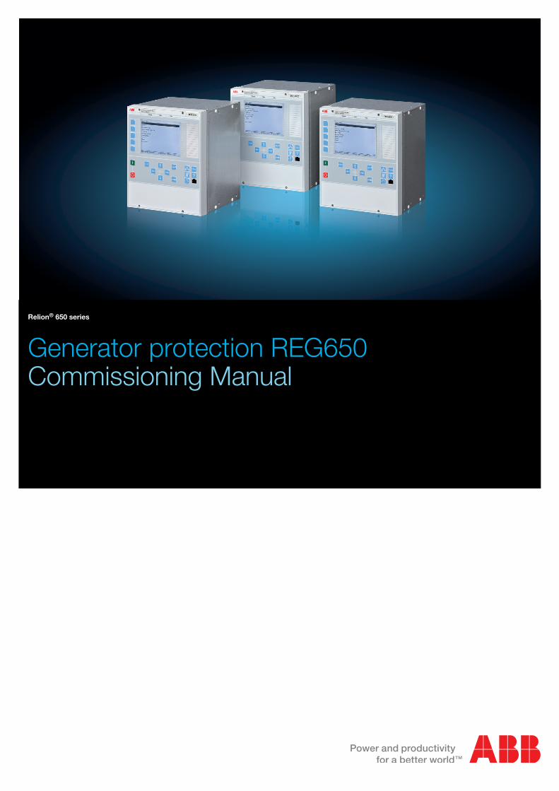
Relion ® 650 series Generator protection REG650 Commissioning Manual
-
Upload
oo-haryatko -
Category
Documents
-
view
44 -
download
2
description
ELEC ENG HB
Transcript of 1mrk502035-Uen - En Commissioning Manual Generator Protection Reg650 Iec
Relion® 650 series
Generator protection REG650Commissioning Manual

Document ID: 1MRK 502 035-UENIssued: February 2011
Revision: -Product version: 1.1
© Copyright 2011 ABB. All rights reserved
CopyrightThis document and parts thereof must not be reproduced or copied without writtenpermission from ABB, and the contents thereof must not be imparted to a thirdparty, nor used for any unauthorized purpose.
The software or hardware described in this document is furnished under a licenseand may be used or disclosed only in accordance with the terms of such license.
TrademarksABB and Relion are registered trademarks of ABB Group. All other brand orproduct names mentioned in this document may be trademarks or registeredtrademarks of their respective holders.
WarrantyPlease inquire about the terms of warranty from your nearest ABB representative.
ABB AB
Substation Automation Products
SE-721 59 Västerås
Sweden
Telephone: +46 (0) 21 32 50 00
Facsimile: +46 (0) 21 14 69 18
http://www.abb.com/substationautomation

ConformityThis product complies with the directive of the Council of the EuropeanCommunities on the approximation of the laws of the Member States relating toelectromagnetic compatibility (EMC Directive 2004/108/EC) and concerningelectrical equipment for use within specified voltage limits (Low-voltage directive2006/95/EC). This conformity is the result of tests conducted by ABB inaccordance with the product standards EN 50263 and EN 60255-26 for the EMCdirective, and with the product standards EN 60255-1 and EN 60255-27 for the lowvoltage directive. The IED is designed in accordance with the internationalstandards of the IEC 60255 series.

DisclaimerThe data, examples and diagrams in this manual are included solely for the conceptor product description and are not to be deemed as a statement of guaranteedproperties. All persons responsible for applying the equipment addressed in thismanual must satisfy themselves that each intended application is suitable andacceptable, including that any applicable safety or other operational requirementsare complied with. In particular, any risks in applications where a system failure and/or product failure would create a risk for harm to property or persons (including butnot limited to personal injuries or death) shall be the sole responsibility of theperson or entity applying the equipment, and those so responsible are herebyrequested to ensure that all measures are taken to exclude or mitigate such risks.
This document has been carefully checked by ABB but deviations cannot becompletely ruled out. In case any errors are detected, the reader is kindly requestedto notify the manufacturer. Other than under explicit contractual commitments, inno event shall ABB be responsible or liable for any loss or damage resulting fromthe use of this manual or the application of the equipment.
Safety information
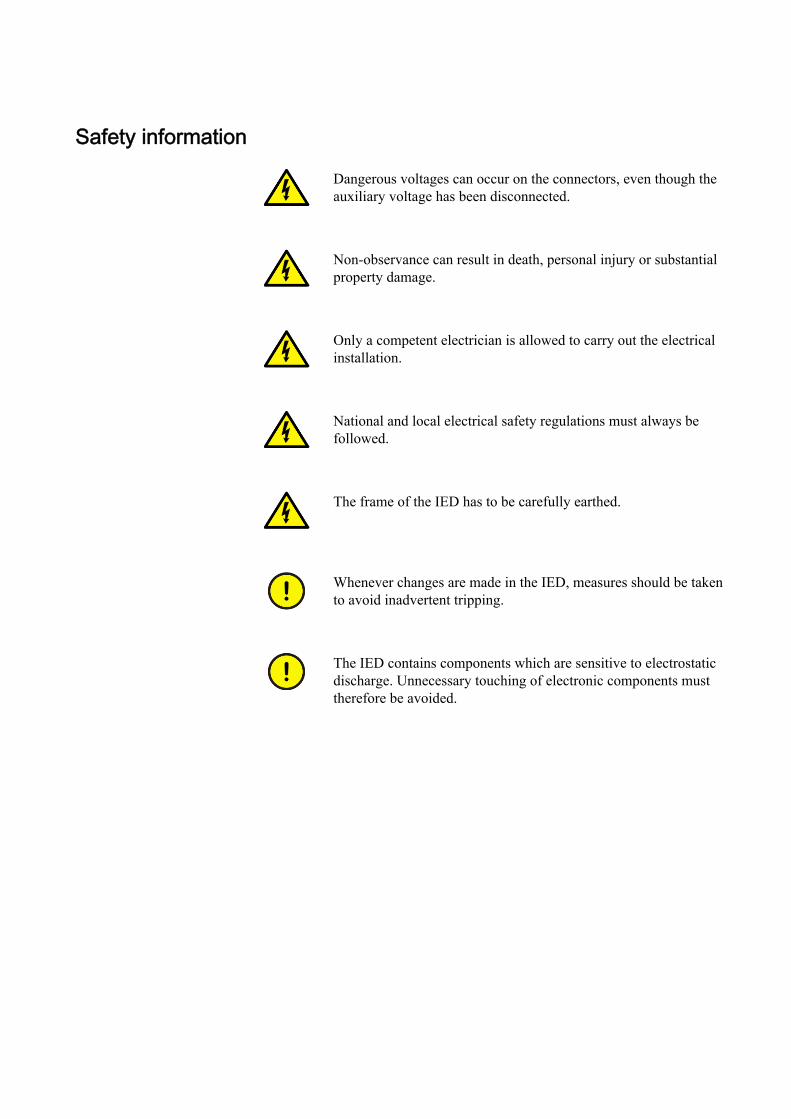
Dangerous voltages can occur on the connectors, even though theauxiliary voltage has been disconnected.
Non-observance can result in death, personal injury or substantialproperty damage.
Only a competent electrician is allowed to carry out the electricalinstallation.
National and local electrical safety regulations must always befollowed.
The frame of the IED has to be carefully earthed.
Whenever changes are made in the IED, measures should be takento avoid inadvertent tripping.
The IED contains components which are sensitive to electrostaticdischarge. Unnecessary touching of electronic components musttherefore be avoided.

Table of contents
Section 1 Introduction.......................................................................7This manual........................................................................................7Intended audience..............................................................................7Product documentation.......................................................................8
Product documentation set............................................................8Document revision history.............................................................9Related documents........................................................................9
Symbols and conventions.................................................................10Safety indication symbols............................................................10Manual conventions.....................................................................11
Section 2 Available functions.........................................................13Main protection functions..................................................................13Back-up protection functions............................................................13Control and monitoring functions......................................................14Designed to communicate................................................................16Basic IED functions..........................................................................17
Section 3 Starting up......................................................................19Factory and site acceptance testing.................................................19Commissioning checklist..................................................................19Checking the power supply..............................................................20Energizing the IED............................................................................20
Checking the IED operation.........................................................20IED start-up sequence.................................................................20
Setting up communication between PCM600 and the IED...............21Writing an application configuration to the IED.................................25Checking CT circuits.........................................................................26Checking VT circuits.........................................................................26Checking the RTXP test switch .......................................................27Checking binary input and output circuits.........................................28
Binary input circuits.....................................................................28Binary output circuits...................................................................28
Checking optical connections...........................................................28
Section 4 Establishing connection and verifying the IEC 61850station communication....................................................29Setting the station communication....................................................29Verifying the communication............................................................29
Table of contents
1Commissioning Manual
Section 5 Testing IED operation.....................................................31Preparing the IED to verify settings..................................................31Activating test mode.........................................................................33Preparing the connection to the test equipment...............................33Connecting test equipment to the IED..............................................34Releasing the function to be tested..................................................35Verifying analog primary and secondary measurement...................35Testing protection functionality.........................................................37
Section 6 Testing functionality........................................................39Testing disturbance report................................................................39
Introduction..................................................................................39Disturbance report settings..........................................................39
Identifying the function to test in the technical referencemanual .............................................................................................39Testing differential protection functions............................................40
Transformer differential protection T3WPDIF .............................40Verifying the settings..............................................................40Completing the test................................................................41
High impedance differential protection HZPDIF .........................41Verifying the settings..............................................................41Completing the test................................................................42
Generator differential protection GENPDIF ................................42Verifying the settings..............................................................42Completing the test................................................................43
Testing impedance protection functions...........................................43Underimpedance protection for generators andtransformers ZGPDIS .................................................................43
Distance protection zones ZGPDIS........................................44Phase-to-phase faults............................................................44
Loss of excitation LEXPDIS ........................................................45Verifying the settings..............................................................45Completing the test................................................................46
Out-of-step OOSPPAM...............................................................47Verifying the settings..............................................................47
Load encroachment LEPDIS ......................................................50Measuring the operate limit of set values...............................51Completing the test................................................................51
Testing current protection functions.................................................51Four step phase overcurrent protection OC4PTOC....................51
Verifying the settings..............................................................51Completing the test................................................................52
Four step residual overcurrent protection EF4PTOC .................53
Table of contents
2Commissioning Manual
Four step directional residual overcurrent protection ............53Four step non-directional residual overcurrentprotection................................................................................54Completing the test................................................................54
Sensitive directional residual overcurrent and powerprotection SDEPSDE ..................................................................54
Measuring the operate and time limit for set values...............54Completing the test................................................................59
Thermal overload protection, two time constants TRPTTR ........59Checking operate and reset values........................................59Completing the test................................................................60
Breaker failure protection CCRBRF............................................60Checking the phase current operate value, IP>.....................61Checking the residual (earth fault) current operate valueIN> set below IP>...................................................................61Checking the re-trip and back-up times..................................61Verifying the re-trip mode.......................................................62Verifying the back-up trip mode..............................................62Verifying the case RetripMode = Contact...............................63Verifying the function mode Current&Contact........................64Completing the test................................................................65
Pole discordance protection CCRPLD........................................65Verifying the settings..............................................................65Completing the test................................................................65
Directional underpower protection GUPPDUP ...........................66Verifying the settings..............................................................66Completing the test................................................................67
Directional overpower protection GOPPDOP .............................68Verifying the settings..............................................................68Completing the test................................................................69
Accidental energizing protection for synchronous generatorAEGGAPC...................................................................................69
Verifying the settings..............................................................69Negative-sequence time overcurrent protection formachines NS2PTOC ..................................................................69
Verifying settings by secondary injection...............................70Voltage-restrained time overcurrent protection VR2PVOC ........71
Verifying the settings..............................................................72Completing the test................................................................73
Testing voltage protection functions.................................................73Two step undervoltage protection UV2PTUV .............................73
Verifying the setting................................................................73Completing the test................................................................74
Two step overvoltage protection OV2PTOV ...............................74
Table of contents
3Commissioning Manual
Verifying the settings..............................................................74Completing the test................................................................74
Two step residual overvoltage protection ROV2PTOV ..............74Verifying the settings..............................................................75Completing the test................................................................75
Overexcitation protection OEXPVPH .........................................75Verifying the settings..............................................................75Completing the test................................................................76
100% Stator earth fault protection, 3rd harmonic basedSTEFPHIZ ..................................................................................76
Testing....................................................................................76Verifying settings....................................................................78Completing the test................................................................78
Rotor earth fault protection 64R..................................................79Testing frequency protection functions.............................................79
Underfrequency protection SAPTUF ..........................................79Verifying the settings..............................................................79Completing the test................................................................80
Overfrequency protection SAPTOF ............................................80Verifying the settings..............................................................81Completing the test................................................................81
Rate-of-change frequency protection SAPFRC ..........................82Verifying the settings..............................................................82Completing the test................................................................82
Testing secondary system supervision functions.............................83Fuse failure supervision SDDRFUF............................................83
Checking that the binary inputs and outputs operate asexpected ................................................................................83Measuring the operate value for the negative sequencefunction ..................................................................................84Measuring the operate value for the zero-sequencefunction ..................................................................................84Checking the operation of the du/dt and di/dt basedfunction ..................................................................................85Completing the test................................................................85
Testing control functions...................................................................86Synchrocheck, energizing check, and synchronizingSESRSYN...................................................................................86
Testing the synchronizing function.........................................88Testing the synchrocheck check............................................88Testing the energizing check..................................................91Testing the voltage selection..................................................92Completing the test................................................................92
Testing logic functions......................................................................93
Table of contents
4Commissioning Manual
Tripping logic SMPPTRC ............................................................93Three phase operating mode.................................................93Circuit breaker lockout............................................................93Completing the test................................................................94
Testing monitoring functions.............................................................94Event counter CNTGGIO.............................................................94
Testing metering functions...............................................................94Pulse counter PCGGIO...............................................................94
Exit test mode...................................................................................95
Section 7 Commissioning and maintenance of the faultclearing system..............................................................97Commissioning and maintenance of the fault clearing system.........97
Installation and commissioning....................................................97Commissioning tests...................................................................98Periodic maintenance tests.........................................................98
Visual inspection....................................................................99Maintenance tests..................................................................99
Section 8 Troubleshooting ...........................................................103Fault tracing....................................................................................103
Identifying hardware errors........................................................103Identifying runtime errors...........................................................103Identifying communication errors...............................................103
Checking the communication link operation.........................104Checking the time synchronization.......................................104
Running the display test............................................................104Indication messages.......................................................................105
Internal faults.............................................................................105Warnings...................................................................................105Additional indications.................................................................106
Correction procedures....................................................................106Changing and setting the password..........................................106Identifying IED application problems.........................................106
Inspecting the wiring.............................................................107
Section 9 Glossary.......................................................................111
Table of contents
5Commissioning Manual

6
Section 1 Introduction
1.1 This manual
The commissioning manual contains instructions on how to commission the IED.The manual can also be used by system engineers and maintenance personnel forassistance during the testing phase. The manual provides procedures for checkingof external circuitry and energizing the IED, parameter setting and configuration aswell as verifying settings by secondary injection. The manual describes the processof testing an IED in a substation which is not in service. The chapters are organizedin chronological order in which the IED should be commissioned.
1.2 Intended audience
This manual addresses the personnel responsible for commissioning, maintenanceand taking the IED in and out of normal service.
The commissioning personnel must have a basic knowledge of handling electronicequipment. The commissioning and maintenance personnel must be wellexperienced in using protection equipment, test equipment, protection functionsand the configured functional logics in the IED.
1MRK 502 035-UEN - Section 1Introduction
7Commissioning Manual
1.3 Product documentation
1.3.1 Product documentation set
Pla
nnin
g &
pur
chas
e
Eng
inee
ring
Inst
allin
g
Com
mis
sion
ing
Ope
ratio
n
Mai
nten
ance
Dec
omm
issi
onin
gde
inst
allin
g&
dis
posa
l
Application manual
Operation manual
Installation manual
Service manual
Engineering manual
Commissioning manual
Communication protocolmanual
Technical manual
Pla
nnin
g &
pur
chas
e
Eng
inee
ring
Inst
allin
g
Com
mis
sion
ing
Ope
ratio
n
Mai
nten
ance
Dec
omm
issi
onin
gde
inst
allin
g&
dis
posa
l
Pla
nnin
g &
pur
chas
e
Eng
inee
ring
Inst
allin
g
Com
mis
sion
ing
Ope
ratio
n
Mai
nten
ance
Dec
omm
issi
onin
gde
inst
allin
g&
dis
posa
l
Application manualApplication manual
Operation manualOperation manual
Installation manualInstallation manual
Service manualService manual
Engineering manualEngineering manual
Commissioning manualCommissioning manual
Communication protocolmanualCommunication protocolmanual
Technical manualTechnical manual
en07000220.vsd
IEC07000220 V1 EN
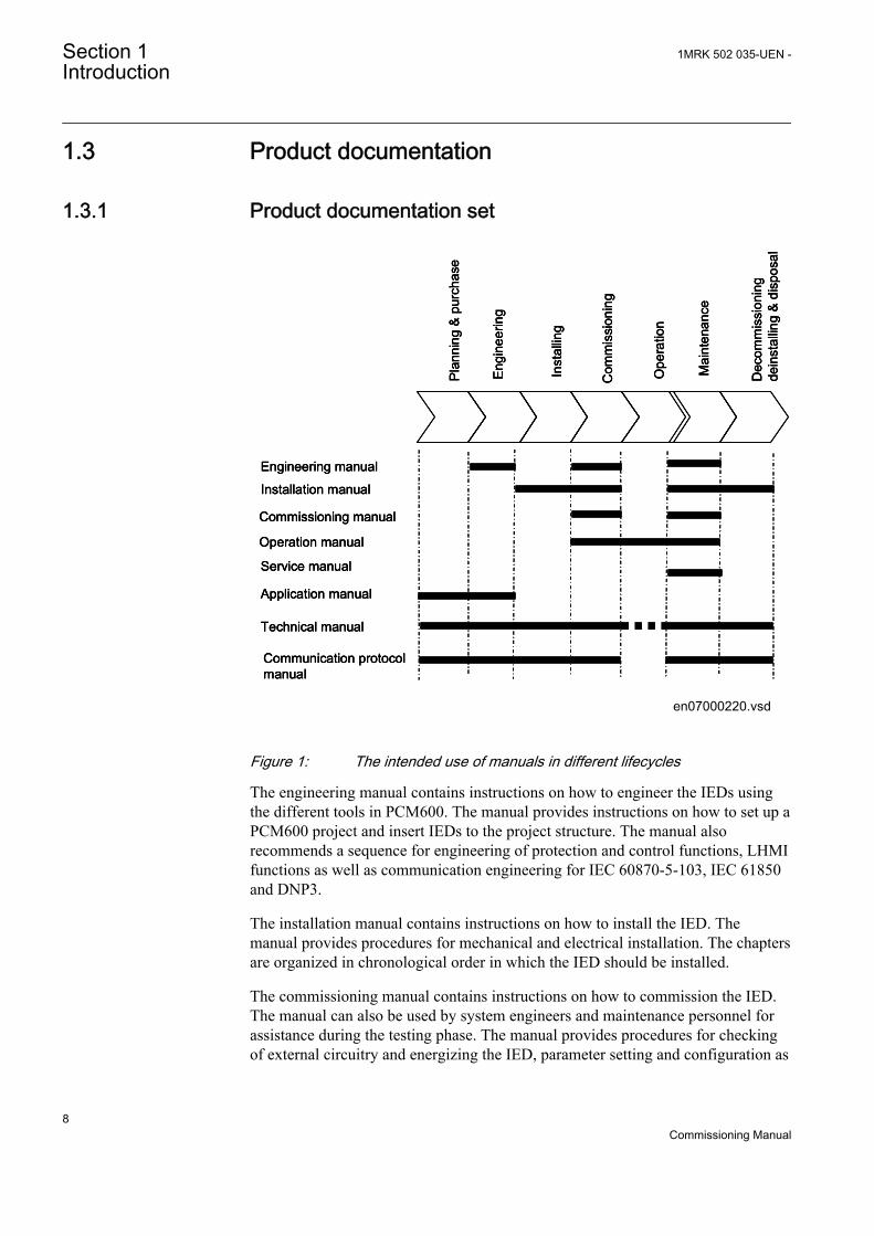
Figure 1: The intended use of manuals in different lifecycles
The engineering manual contains instructions on how to engineer the IEDs usingthe different tools in PCM600. The manual provides instructions on how to set up aPCM600 project and insert IEDs to the project structure. The manual alsorecommends a sequence for engineering of protection and control functions, LHMIfunctions as well as communication engineering for IEC 60870-5-103, IEC 61850and DNP3.
The installation manual contains instructions on how to install the IED. Themanual provides procedures for mechanical and electrical installation. The chaptersare organized in chronological order in which the IED should be installed.
The commissioning manual contains instructions on how to commission the IED.The manual can also be used by system engineers and maintenance personnel forassistance during the testing phase. The manual provides procedures for checkingof external circuitry and energizing the IED, parameter setting and configuration as
Section 1 1MRK 502 035-UEN -Introduction
8Commissioning Manual
well as verifying settings by secondary injection. The manual describes the processof testing an IED in a substation which is not in service. The chapters are organizedin chronological order in which the IED should be commissioned.
The operation manual contains instructions on how to operate the IED once it hasbeen commissioned. The manual provides instructions for monitoring, controllingand setting the IED. The manual also describes how to identify disturbances andhow to view calculated and measured power grid data to determine the cause of afault.
The service manual contains instructions on how to service and maintain the IED.The manual also provides procedures for de-energizing, de-commissioning anddisposal of the IED.
The application manual contains application descriptions and setting guidelinessorted per function. The manual can be used to find out when and for what purposea typical protection function can be used. The manual can also be used whencalculating settings.
The technical manual contains application and functionality descriptions and listsfunction blocks, logic diagrams, input and output signals, setting parameters andtechnical data sorted per function. The manual can be used as a technical referenceduring the engineering phase, installation and commissioning phase, and duringnormal service.
The communication protocol manual describes a communication protocolsupported by the IED. The manual concentrates on vendor-specific implementations.
The point list manual describes the outlook and properties of the data pointsspecific to the IED. The manual should be used in conjunction with thecorresponding communication protocol manual.
The service manual is not available yet.
1.3.2 Document revision historyDocument revision/date Product series version History-/February 2011 1.1 First release
1.3.3 Related documentsDocuments related to REG650 Identity numberApplication manual 1MRK 502 033-UEN
Technical manual 1MRK 502 034-UEN
Commissioning manual 1MRK 502 035-UEN
Table continues on next page
1MRK 502 035-UEN - Section 1Introduction
9Commissioning Manual
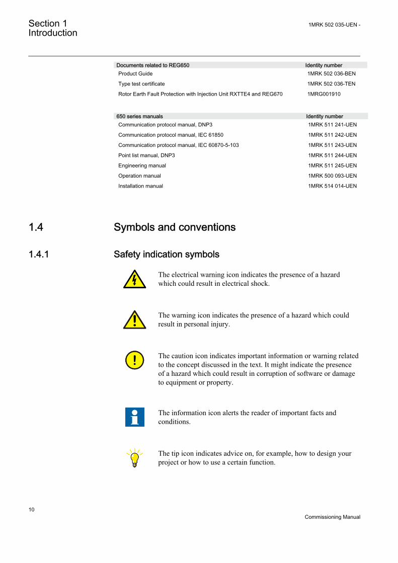
Documents related to REG650 Identity numberProduct Guide 1MRK 502 036-BEN
Type test certificate 1MRK 502 036-TEN
Rotor Earth Fault Protection with Injection Unit RXTTE4 and REG670 1MRG001910
650 series manuals Identity numberCommunication protocol manual, DNP3 1MRK 511 241-UEN
Communication protocol manual, IEC 61850 1MRK 511 242-UEN
Communication protocol manual, IEC 60870-5-103 1MRK 511 243-UEN
Point list manual, DNP3 1MRK 511 244-UEN
Engineering manual 1MRK 511 245-UEN
Operation manual 1MRK 500 093-UEN
Installation manual 1MRK 514 014-UEN
1.4 Symbols and conventions
1.4.1 Safety indication symbols
The electrical warning icon indicates the presence of a hazardwhich could result in electrical shock.
The warning icon indicates the presence of a hazard which couldresult in personal injury.
The caution icon indicates important information or warning relatedto the concept discussed in the text. It might indicate the presenceof a hazard which could result in corruption of software or damageto equipment or property.
The information icon alerts the reader of important facts andconditions.
The tip icon indicates advice on, for example, how to design yourproject or how to use a certain function.
Section 1 1MRK 502 035-UEN -Introduction
10Commissioning Manual
Although warning hazards are related to personal injury, it is necessary tounderstand that under certain operational conditions, operation of damagedequipment may result in degraded process performance leading to personal injuryor death. Therefore, comply fully with all warning and caution notices.
1.4.2 Manual conventionsConventions used in IED manuals. A particular convention may not be used in thismanual.
• Abbreviations and acronyms in this manual are spelled out in the glossary. Theglossary also contains definitions of important terms.
• Push button navigation in the LHMI menu structure is presented by using thepush button icons, for example:To navigate between the options, use and .
• HMI menu paths are presented in bold, for example:Select Main menu/Settings.
• LHMI messages are shown in Courier font, for example:To save the changes in non-volatile memory, select Yes and press .
• Parameter names are shown in italics, for example:The function can be enabled and disabled with the Operation setting.
• The ^ character in front of an input or output signal name in the function blocksymbol given for a function, indicates that the user can set an own signal namein PCM600.
• The * character after an input or output signal name in the function blocksymbol given for a function, indicates that the signal must be connected toanother function block in the application configuration to achieve a validapplication configuration.
1MRK 502 035-UEN - Section 1Introduction
11Commissioning Manual

12
Section 2 Available functions
Note that not all functions included in the tables below havecommissioning information available.
2.1 Main protection functions
IEC 61850/Function blockname
ANSI Function description Generator
REG
650
(B01
)G
en d
iff
REG
650
(B05
)G
en+T
rafo
diff
Differential protection
T3WPDIF 87T Transformer differential protection, three winding 1
HZPDIF 87 1Ph High impedance differential protection 1 1
GENPDIF 87G Generator differential protection 1
Impedance protection
ZGPDIS 21G Underimpedance protection for generators and transformers 1 1
LEXPDIS 40 Loss of excitation 1 1
OOSPPAM 78 Out-of-step protection 1 1
LEPDIS Load encroachment 1 1
2.2 Back-up protection functions
IEC 61850/Function blockname
ANSI Function description Generator
REG
650
(B01
)G
en d
iff
REG
650
(B05
)G
en+T
rafo
diff
Current protection
OC4PTOC 51/67 Four step directional phase overcurrent protection 2 2
EF4PTOC 51N/67N Four step directional residual overcurrent protection 2 2
SDEPSDE 67N Sensitive directional residual overcurrent and power protection 1 1
Table continues on next page
1MRK 502 035-UEN - Section 2Available functions
13Commissioning Manual
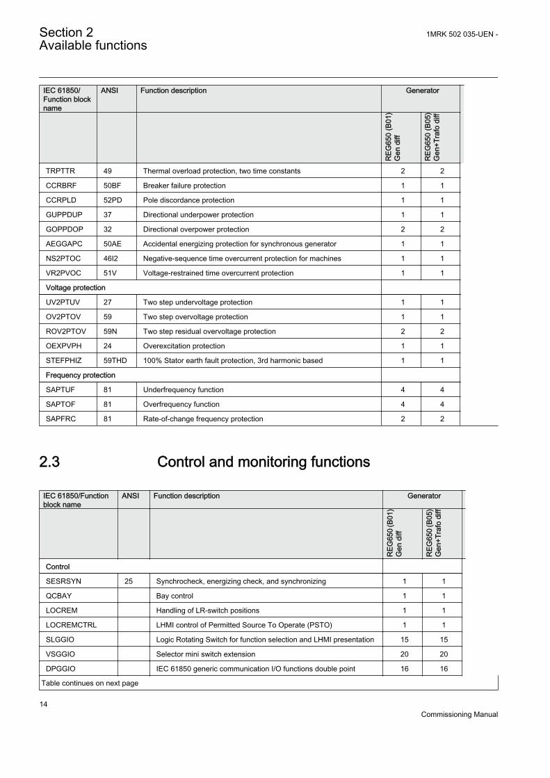
IEC 61850/Function blockname
ANSI Function description Generator
REG
650
(B01
)G
en d
iff
REG
650
(B05
)G
en+T
rafo
diff
TRPTTR 49 Thermal overload protection, two time constants 2 2
CCRBRF 50BF Breaker failure protection 1 1
CCRPLD 52PD Pole discordance protection 1 1
GUPPDUP 37 Directional underpower protection 1 1
GOPPDOP 32 Directional overpower protection 2 2
AEGGAPC 50AE Accidental energizing protection for synchronous generator 1 1
NS2PTOC 46I2 Negative-sequence time overcurrent protection for machines 1 1
VR2PVOC 51V Voltage-restrained time overcurrent protection 1 1
Voltage protection
UV2PTUV 27 Two step undervoltage protection 1 1
OV2PTOV 59 Two step overvoltage protection 1 1
ROV2PTOV 59N Two step residual overvoltage protection 2 2
OEXPVPH 24 Overexcitation protection 1 1
STEFPHIZ 59THD 100% Stator earth fault protection, 3rd harmonic based 1 1
Frequency protection
SAPTUF 81 Underfrequency function 4 4
SAPTOF 81 Overfrequency function 4 4
SAPFRC 81 Rate-of-change frequency protection 2 2
2.3 Control and monitoring functions
IEC 61850/Functionblock name
ANSI Function description Generator
REG
650
(B01
)G
en d
iff
REG
650
(B05
)G
en+T
rafo
diff
Control
SESRSYN 25 Synchrocheck, energizing check, and synchronizing 1 1
QCBAY Bay control 1 1
LOCREM Handling of LR-switch positions 1 1
LOCREMCTRL LHMI control of Permitted Source To Operate (PSTO) 1 1
SLGGIO Logic Rotating Switch for function selection and LHMI presentation 15 15
VSGGIO Selector mini switch extension 20 20
DPGGIO IEC 61850 generic communication I/O functions double point 16 16
Table continues on next page
Section 2 1MRK 502 035-UEN -Available functions
14Commissioning Manual
IEC 61850/Functionblock name
ANSI Function description Generator
REG
650
(B01
)G
en d
iff
REG
650
(B05
)G
en+T
rafo
diff
SPC8GGIO Single point generic control 8 signals 5 5
AUTOBITS AutomationBits, command function for DNP3.0 3 3
I103CMD Function commands for IEC60870-5-103 1 1
I103IEDCMD IED commands for IEC60870-5-103 1 1
I103USRCMD Function commands user defined for IEC60870-5-103 4 4
I103GENCMD Function commands generic for IEC60870-5-103 50 50
I103POSCMD IED commands with position and select for IEC60870-5-103 50 50
Secondary system supervision
SDDRFUF Fuse failure supervision 1 1
TCSSCBR Breaker close/trip circuit monitoring 3 3
Logic
SMPPTRC 94 Tripping logic 6 6
TMAGGIO Trip matrix logic 12 12
OR Configurable logic blocks, OR gate 283 283
INVERTER Configurable logic blocks, Inverter gate 140 140
PULSETIMER Configurable logic blocks, Pulse timer 40 40
GATE Configurable logic blocks, Controllable gate 40 40
XOR Configurable logic blocks, exclusive OR gate 40 40
LOOPDELAY Configurable logic blocks, loop delay 40 40
TIMERSET Configurable logic blocks, timer function block 40 40
AND Configurable logic blocks, AND gate 280 280
SRMEMORY Configurable logic blocks, set-reset memory flip-flop gate 40 40
RSMEMORY Configurable logic blocks, reset-set memory flip-flop gate 40 40
FXDSIGN Fixed signal function block 1 1
B16I Boolean 16 to Integer conversion 16 16
B16IFCVI Boolean 16 to Integer conversion with logic node representation 16 16
IB16A Integer to Boolean 16 conversion 16 16
IB16FCVB Integer to Boolean 16 conversion with logic node representation 16 16
Monitoring
CVMMXN Measurements 6 6
CMMXU Phase current measurement 10 10
VMMXU Phase-phase voltage measurement 6 6
CMSQI Current sequence component measurement 6 6
VMSQI Voltage sequence measurement 6 6
VNMMXU Phase-neutral voltage measurement 6 6
Table continues on next page
1MRK 502 035-UEN - Section 2Available functions
15Commissioning Manual
IEC 61850/Functionblock name
ANSI Function description Generator
REG
650
(B01
)G
en d
iff
REG
650
(B05
)G
en+T
rafo
diff
CNTGGIO Event counter 5 5
DRPRDRE Disturbance report 1 1
AxRADR Analog input signals 4 4
BxRBDR Binary input signals 6 6
SPGGIO IEC 61850 generic communication I/O functions 64 64
SP16GGIO IEC 61850 generic communication I/O functions 16 inputs 16 16
MVGGIO IEC 61850 generic communication I/O functions 16 16
MVEXP Measured value expander block 66 66
SPVNZBAT Station battery supervision 1 1
SSIMG 63 Insulation gas monitoring function 2 2
SSIML 71 Insulation liquid monitoring function 2 2
SSCBR Circuit breaker condition monitoring 1 1
I103MEAS Measurands for IEC60870-5-103 1 1
I103MEASUSR Measurands user defined signals for IEC60870-5-103 3 3
I103AR Function status auto-recloser for IEC60870-5-103 1 1
I103EF Function status earth-fault for IEC60870-5-103 1 1
I103FLTPROT Function status fault protection for IEC60870-5-103 1 1
I103IED IED status for IEC60870-5-103 1 1
I103SUPERV Supervison status for IEC60870-5-103 1 1
I103USRDEF Status for user defined signals for IEC60870-5-103 20 20
Metering
PCGGIO Pulse counter logic 16 16
ETPMMTR Function for energy calculation and demand handling 3 3
2.4 Designed to communicate
IEC 61850/Function blockname
ANSI Function description Generator
REG
650
(B01
)G
en d
iff
REG
650
(B05
)G
en+T
rafo
diff
Station communication
IEC 61850 communication protocol, LAN1 1 1
DNP3.0 for TCP/IP communication protocol, LAN1 1 1
Table continues on next page
Section 2 1MRK 502 035-UEN -Available functions
16Commissioning Manual
IEC 61850/Function blockname
ANSI Function description Generator
REG
650
(B01
)G
en d
iff
REG
650
(B05
)G
en+T
rafo
diff
IEC61870-5-103 IEC60870-5-103 serial communication via ST 1 1
GOOSEINTLKRCV Horizontal communication via GOOSE for interlocking 59 59
GOOSEBINRCV GOOSE binary receive 4 4
ETHFRNTETHLAN1GATEWAY
Ethernet configuration of front port, LAN1 port and gateway
GOOSEDPRCV GOOSE function block to receive a double point value 32 32
GOOSEINTRCV GOOSE function block to receive an integer value 32 32
GOOSEMVRCV GOOSE function block to receive a mesurand value 16 16
GOOSESPRCV GOOSE function block to receive a single point value 64 64
2.5 Basic IED functions
IEC 61850/Functionblock name
Function description
Basic functions included in all products
INTERRSIG Self supervision with internal event list 1
SELFSUPEVLST Self supervision with internal event list 1
SNTP Time synchronization 1
TIMESYNCHGEN Time synchronization 1
DTSBEGIN, DTSEND,TIMEZONE
Time synchronization, daylight saving 1
IRIG-B Time synchronization 1
SETGRPS Setting group handling 1
ACTVGRP Parameter setting groups 1
TESTMODE Test mode functionality 1
CHNGLCK Change lock function 1
TERMINALID IED identifiers 1
PRODINF Product information 1
PRIMVAL Primary system values 1
SMAI_20_1-12 Signal matrix for analog inputs 2
3PHSUM Summation block 3 phase 12
GBASVAL Global base values for settings 6
ATHSTAT Authority status 1
ATHCHCK Authority check 1
FTPACCS FTP access with password 1
Table continues on next page
1MRK 502 035-UEN - Section 2Available functions
17Commissioning Manual

IEC 61850/Functionblock name
Function description
DOSFRNT Denial of service, frame rate control for front port 1
DOSLAN1 Denial of service, frame rate control for LAN1 1
DOSSCKT Denial of service, socket flow control 1
Section 2 1MRK 502 035-UEN -Available functions
18Commissioning Manual
Section 3 Starting up
3.1 Factory and site acceptance testing
Testing the proper IED operation is carried out at different occasions, for example:
• Acceptance testing• Commissioning testing• Maintenance testing
This manual describes the workflow and the steps to carry out the commissioningtesting.
Factory acceptance testing (FAT) is typically done to verify that the IED andconfiguration meets the requirements by the utility or industry. This test is the mostcomplex and in depth, as it is done to familiarize the user to a new protection or toverify a new configuration. The complexity of this testing depends on several factors.
• New IED type• New configuration• Pre-configured• Modified existing configuration
Site acceptance testing (SAT or commissioning testing) is typically done to verifythat the new installed IED is correctly set and connected to the power system. SATrequires that the acceptance testing has been performed and that the applicationconfiguration is verified.
Maintenance testing is a periodical verification that the IED is healthy and hascorrect settings depending on changes in the power system. There are also othertypes of maintenance testing.
3.2 Commissioning checklist
Before starting up commissioning at site, check that the following items are available.
• Single line diagram• Protection block diagram• Circuit diagram• Setting list and configuration• RJ-45 Ethernet cable (CAT 5)• Three-phase test kit or other test equipment depending on the complexity of
the configuration and functions to be tested.
1MRK 502 035-UEN - Section 3Starting up
19Commissioning Manual
• PC with PCM600 installed along with the connectivity packagescorresponding to the IED used
• Administration rights on the PC to set up IP addresses• Product documentation (engineering manual, installation manual,
commissioning manual, operation manual, technical manual andcommunication protocol manual)
3.3 Checking the power supply
Check that the auxiliary supply voltage remains within the permissible inputvoltage range under all operating conditions. Check that the polarity is correctbefore powering the IED.
3.4 Energizing the IED
3.4.1 Checking the IED operationCheck all connections to external circuitry to ensure that the installation was madecorrectly, before energizing the IED and carrying out the commissioning procedures.
Energize the power supply of the IED to start it up. This could be done in numberof ways, from energizing a whole cubicle to energizing a single IED. Set the IEDtime if no time synchronization source is configured.Check also the self-supervision function in Main menu/Diagnostics/Internal events or Main menu/Diagnostics/IED status/General menu in local HMI to verify that the IEDoperates properly.
3.4.2 IED start-up sequenceThe following sequence is expected when the IED is energized.
• The green Ready LED starts instantly flashing and the ABB logo is shown onthe LCD.
• After approximately 30 seconds, "Starting" is shown on the LCD.• Within 90 seconds, the main menu is shown on the LCD and the green Ready
LED shows a steady light, which indicates a successful startup.
The start-up times depend on the size of the applicationconfiguration. Application configuration with less functionalitymeans shorter start-up times.
Section 3 1MRK 502 035-UEN -Starting up
20Commissioning Manual
If the green Ready LED continues to flash after startup, the IED has detected aninternal error. Navigate via Main menu/Diagnostics/IED status/General toinvestigate the fault.
3.5 Setting up communication between PCM600 andthe IED
The communication between the IED and PCM600 is independent of the usedcommunication protocol within the substation or to the NCC.
The communication media is always Ethernet and the used protocol is TCP/IP.
Each IED has an Ethernet interface connector on the front and on the rear side. TheEthernet connector can be used for communication with PCM600.
When an Ethernet-based station protocol is used, PCM600 communication can usethe same Ethernet port and IP address.
For the connection of PCM600 to the IED, two basic variants have to be considered.
• Direct point-to-point link between PCM600 and the IED front port.• Indirect link via a station LAN or from remote via a network.
The physical connection and the IP address must be configured in both cases toenable communication.
The communication procedures are the same in both cases.
1. If needed, set the IP address for the IEDs.2. Set up the PC or workstation for a direct link (point-to-point), or3. Connect the PC or workstation to the LAN/WAN network.4. Configure the IED IP addresses in the PCM600 project for each IED to match
the IP addresses of the physical IEDs.
Setting up IP addressesThe IP address and the corresponding mask must be set via the LHMI for eachavailable Ethernet interface in the IED. Each Ethernet interface has a defaultfactory IP address when the complete IED is delivered. This is not given when anadditional Ethernet interface is installed or an interface is replaced.
• The default IP address for the IED front port is 10.1.150.3 and thecorresponding subnetwork mask is 255.255.255.0, which can be set via thelocal HMI path Main menu/Configuration/Communication/TCP-IPconfiguration/1:ETHFRNT.
• The default IP address for the IED rear port is 192.168.1.10 and thecorresponding subnetwork mask is 255.255.255.0, which can be set via the
1MRK 502 035-UEN - Section 3Starting up
21Commissioning Manual
local HMI path Main menu/Configuration/Communication/TCP-IPconfiguration/1:ETHLAN1 and Rear OEM - port CD.
The front and rear port IP addresses cannot belong to the samesubnet or communication will fail. It is recommended to change theIP address of the front port, if the front and rear port are set to thesame subnet.
Setting up the PC or workstation for point-to-point access to IEDsfront portA special cable is needed to connect two physical Ethernet interfaces togetherwithout a hub, router, bridge or switch in between. The Tx and Rx signal wiresmust be crossed in the cable to connect Tx with Rx on the other side and viceversa. These cables are known as null-modem cables or cross-wired cables. Themaximum length should be about 2 m. The connector type is RJ-45.
IEC09000096-1-en.vsd
PCM600
Tx Tx
Rx Rx
RJ-45IED
IEC09000096 V1 EN
Figure 2: Point-to-point link between IED and PCM600 using a null-modemcable
The following description is an example valid for standard PCs using MicrosoftWindows operating system. The example is taken from a Laptop with one Ethernetinterface.
Administrator rights are requested to change the PC communicationsetup. Some PCs have the feature to automatically detect that Txsignals from the IED are received on the Tx pin on the PC. Thusstraight (standard) Ethernet cable can be used.
When a computer is connected to the IED and the setting DHCPServer is set to Onvia the local HMI path Main menu/Configuration/Communication/TCP-IPconfiguration/1:ETHFRNT/DHCPServer, the IEDs DHCP server for the frontport assigns an IP address for the computer. The computer must be configured toobtain its IP address automatically as described in the following procedure.
1. Select Network Connections in the PC.
Section 3 1MRK 502 035-UEN -Starting up
22Commissioning Manual
IEC09000355-1-en.vsdIEC09000355 V1 EN
Figure 3: Select: Network connections
2. Select Properties in the status window.
IEC09000356-1-en.vsdIEC09000356 V1 EN
Figure 4: Right-click Local Area Connection and select Properties
3. Select the TCP/IP protocol from the list of configured components using thisconnection and click Properties.
1MRK 502 035-UEN - Section 3Starting up
23Commissioning Manual
IEC09000357-1-en.vsdIEC09000357 V1 EN
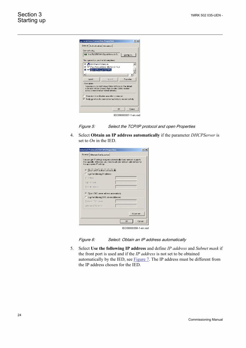
Figure 5: Select the TCP/IP protocol and open Properties
4. Select Obtain an IP address automatically if the parameter DHCPServer isset to On in the IED.
IEC09000358-1-en.vsdIEC09000358 V1 EN
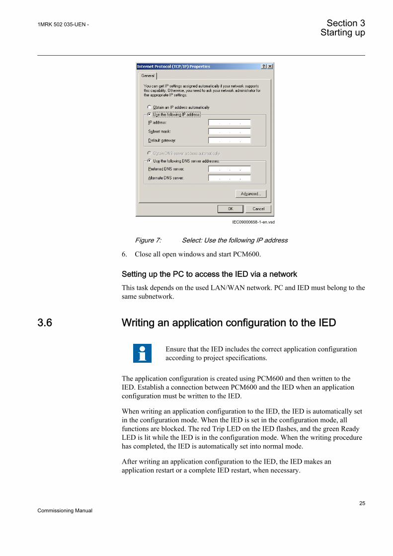
Figure 6: Select: Obtain an IP address automatically
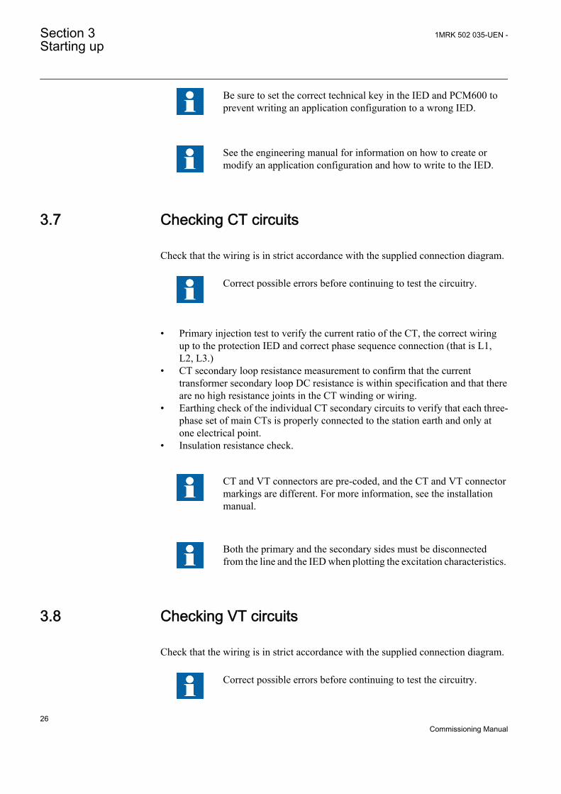
5. Select Use the following IP address and define IP address and Subnet mask ifthe front port is used and if the IP address is not set to be obtainedautomatically by the IED, see Figure 7. The IP address must be different fromthe IP address chosen for the IED.
Section 3 1MRK 502 035-UEN -Starting up
24Commissioning Manual
IEC09000658-1-en.vsdIEC09000658 V1 EN
Figure 7: Select: Use the following IP address
6. Close all open windows and start PCM600.
Setting up the PC to access the IED via a networkThis task depends on the used LAN/WAN network. PC and IED must belong to thesame subnetwork.
3.6 Writing an application configuration to the IED
Ensure that the IED includes the correct application configurationaccording to project specifications.
The application configuration is created using PCM600 and then written to theIED. Establish a connection between PCM600 and the IED when an applicationconfiguration must be written to the IED.
When writing an application configuration to the IED, the IED is automatically setin the configuration mode. When the IED is set in the configuration mode, allfunctions are blocked. The red Trip LED on the IED flashes, and the green ReadyLED is lit while the IED is in the configuration mode. When the writing procedurehas completed, the IED is automatically set into normal mode.
After writing an application configuration to the IED, the IED makes anapplication restart or a complete IED restart, when necessary.
1MRK 502 035-UEN - Section 3Starting up
25Commissioning Manual
Be sure to set the correct technical key in the IED and PCM600 toprevent writing an application configuration to a wrong IED.
See the engineering manual for information on how to create ormodify an application configuration and how to write to the IED.
3.7 Checking CT circuits
Check that the wiring is in strict accordance with the supplied connection diagram.
Correct possible errors before continuing to test the circuitry.
• Primary injection test to verify the current ratio of the CT, the correct wiringup to the protection IED and correct phase sequence connection (that is L1,L2, L3.)
• CT secondary loop resistance measurement to confirm that the currenttransformer secondary loop DC resistance is within specification and that thereare no high resistance joints in the CT winding or wiring.
• Earthing check of the individual CT secondary circuits to verify that each three-phase set of main CTs is properly connected to the station earth and only atone electrical point.
• Insulation resistance check.
CT and VT connectors are pre-coded, and the CT and VT connectormarkings are different. For more information, see the installationmanual.
Both the primary and the secondary sides must be disconnectedfrom the line and the IED when plotting the excitation characteristics.
3.8 Checking VT circuits
Check that the wiring is in strict accordance with the supplied connection diagram.
Correct possible errors before continuing to test the circuitry.
Section 3 1MRK 502 035-UEN -Starting up
26Commissioning Manual
Test the circuitry.
• Polarity check• VT circuit voltage measurement (primary injection test)• Earthing check• Phase relationship• Insulation resistance check
The polarity check verifies the integrity of circuits and the phase relationships. Thecheck must be performed as close to the IED as possible.
The primary injection test verifies the VT ratio and the wiring all the way from theprimary system to the IED. Injection must be performed for each phase-to-neutralcircuit and each phase-to-phase pair. In each case, voltages in all phases andneutral are measured.
3.9 Checking the RTXP test switch
The RTXP test switch is designed to provide the means of safe testing of the IED.This is achieved by the electromechanical design of the test switch and test plughandle. When the test plug handle is inserted, it first blocks the trip and alarmcircuits then it short circuits the CT secondary circuit and opens the VT secondarycircuits making the IED available for secondary injection.
When pulled out, the test handle is mechanically stopped in half withdrawnposition. In this position, the current and voltage enter the protection, but the alarmand trip circuits are still isolated. Before removing the test handle, check that notrip or alarms are present in the IED.
Not until the test handle is completely removed, the trip and alarm circuits arerestored for operation.
By pulling in all cables, verify that the contact sockets have beencrimped correctly and that they are fully inserted. Never do thiswith current circuits in service.
Current circuit
1. Verify that the contacts are of current circuit type.2. Verify that the short circuit jumpers are located in the correct slots.
Voltage circuit
1MRK 502 035-UEN - Section 3Starting up
27Commissioning Manual
1. Verify that the contacts are of voltage circuit type.2. Check that no short circuit jumpers are located in the slots dedicated for voltage.
Trip and alarm circuits
1. Check that the correct types of contacts are used.
3.10 Checking binary input and output circuits
3.10.1 Binary input circuitsPreferably, disconnect the binary input connector from the binary input cards.Check all connected signals so that both input level and polarity are in accordancewith the IED specifications.
3.10.2 Binary output circuitsPreferably, disconnect the binary output connector from the binary output cards.Check all connected signals so that both load and polarity are in accordance withIED specifications.
3.11 Checking optical connections
Check that the Tx and Rx optical connections are correct.
An IED equipped with optical connections requires a minimumdepth of 180 mm for plastic fiber cables and 275 mm for glass fibercables. Check the allowed minimum bending radius from theoptical cable manufacturer.
Section 3 1MRK 502 035-UEN -Starting up
28Commissioning Manual
Section 4 Establishing connection and verifying theIEC 61850 station communication
4.1 Setting the station communication
To enable IEC 61850 station communication:
• The IEC 61850-8-1 station communication functionality must be on in thelocal HMI. Navigate to Main menu/Configuration/Communication/Stationcommunication/1:IEC61850-8-1 and set the parameter Operation to On.
• To enable GOOSE communication the Operation parameter for thecorresponding GOOSE function blocks (GOOSEBINRCV andGOOSEINTLKRCV) must be set to On in the application configuration.
• To enable GOOSE communication via the front port the parameter GOOSE inMain menu/Configuration/Communication/Station communication/IEC61850-8-1 must be set to Front. To enable GOOSE communication viarear port the parameter GOOSE must be set to LAN1.
4.2 Verifying the communication
Connect your PC to the nearby switch and ping the connected IED and theSubstation Master PC, to verify that the communication is working (up to thetransport layer).
The best way to verify the communication up to the application layer is to use aprotocol analyzer, for example, an Ethereal that is connected to the substation bus,and monitor the communication."
1MRK 502 035-UEN - Section 4Establishing connection and verifying the IEC 61850 station communication
29Commissioning Manual

30
Section 5 Testing IED operation
5.1 Preparing the IED to verify settings
If a test switch is included, start preparation by making the necessary connectionsto the test switch. This means connecting the test equipment according to a specificand designated IED terminal diagram.
Put the IED into the test mode to facilitate the test of individual functions andprevent unwanted operation caused by other functions. The test switch should thenbe connected to the IED.
Verify that analog input signals from the analog input module are measured andrecorded correctly by injecting currents and voltages required by the specific IED.
To make testing even more effective, use PCM600. PCM600 includes the Signalmonitoring tool, which is useful in reading the individual currents and voltages,their amplitudes and phase angles. In addition, PCM600 contains the Disturbancehandling tool. The content of reports generated by the Disturbance handling toolcan be configured which makes the work more efficient. For example, the tool maybe configured to only show time tagged events and to exclude analog informationand so on.
Check the disturbance report settings to ensure that the indications are correct.
For test functions and test and signal parameter names, see the technical manual.The correct initiation of the disturbance recorder is made on start and/or release ortrip from a function. Also check that the wanted recordings of analogue (real andcalculated) and binary signals are achieved.
The IEDs in the 650 series can have between 1 to 4 individual parameter settinggroups prepared with full sets of different parameters for all functions. The purposeof these groups is to be able to handle different power system load conditions tooptimize the parameters settings of the different functions for these different powersystems conditions (for example summer/winter and day/night).
Parameters can be entered into different setting groups. Make sureto test functions for the same parameter setting group. If needed,repeat the tests for all different setting groups used. The differencebetween testing the first parameter setting group and the remainingis that there is no need for testing the connections.
During testing, observe that the right testing method, that corresponds to the actualparameters set in the activated parameter setting group, is used.
1MRK 502 035-UEN - Section 5Testing IED operation
31Commissioning Manual
In the local HMI the sensitive directional earth fault protection SDEPSDEparameter group 4 is active indicated by the * next to #4 and the test of theSDEPSDE must be performed according to the instructions given for the settingOpMode and setting value 3I03U0cosfi.
Set and configure the function(s) before testing. Most functions are highly flexibleand permit a choice of functional and tripping modes. The various modes arechecked at the factory as part of the design verification. In certain cases, onlymodes with a high probability of coming into operation need to be checked whencommissioned to verify the configuration and settings.
Requirements for testing the function.
• Calculated settings• Valid configuration diagram for the IED• Valid terminal diagram for the IED• Technical manual• Three-phase test equipment
Content of the technical manual.
• Application and functionality summaries• Function blocks• Logic diagrams• Input and output signals• A list of setting parameters• Technical data for the function
The test equipment should be able to provide a three-phase supply of currents andthree-phase voltage. The magnitude and angle of currents (and voltages) should bepossible to vary. Check that the IED is prepared for test before starting the testsession. Consider the logic diagram of the function when performing the test.
The response from a test can be viewed in different ways.
• Binary output signals• Service values in the local HMI (logical signal or phasors)• A PC with PCM600 (configuration software) in debug mode
Do not switch off the auxiliary power supply to the IED beforechanges such as setting parameter or local/remote control statechanges are saved.
A mechanism for limiting the number of writings per time period is included in theIED to prevent the flash memory to be worn out due to too many writings. As aconsequence it may take up to an hour to save changes. If the auxiliary power isinterrupted before a change is saved, that change is lost.
Section 5 1MRK 502 035-UEN -Testing IED operation
32Commissioning Manual
5.2 Activating test mode
Put the IED into the test mode before testing. The test mode blocks all functions inthe IED, and the individual functions to be tested can be unblocked to preventunwanted operation caused by other functions. In this way, it is possible to testslower back-up measuring functions without the interference from faster measuringfunctions. Test mode is indicated when the yellow Start LED flashes.
Procedure
1. Select Main menu/Tests/IED test mode/1:TESTMODE2. Set parameter TestMode to On.3. Save the changes.
As a consequence, the yellow Start LED starts flashing as a reminder andremains flashing until the test mode is switched off.
5.3 Preparing the connection to the test equipment
The IED can be equipped with a test switch of type RTXP8, RTXP18 or RTXP24.The test switch and its associated test plug handle (RTXH8, RTXH18 or RTXH24)are a part of the COMBITEST system, which provides secure and convenienttesting of the IED.
When using the COMBITEST, preparations for testing are automatically carriedout in the proper sequence, that is, for example, blocking of tripping circuits, shortcircuiting of CT’s, opening of voltage circuits, making IED terminals available forsecondary injection. Terminals 1 and 8, 1 and 18 as well as 1 and 12 of the testswitches RTXP8, RTXP18 and RTXP24 respectively are not disconnected as theysupply DC power to the protection IED.
The RTXH test-plug handle leads may be connected to any type of test equipmentor instrument. When a number of protection IEDs of the same type are tested, thetest-plug handle only needs to be moved from the test switch of one protection IEDto the test switch of the other, without altering the previous connections.
Use COMBITEST test system to prevent unwanted tripping when the handle iswithdrawn, since latches on the handle secure it in the half withdrawn position. Inthis position, all voltages and currents are restored and any reenergizing transientsare given a chance to decay before the trip circuits are restored. When the latchesare released, the handle can be completely withdrawn from the test switch,restoring the trip circuits to the protection IED.
If a test switch is not used, take measures according to provided circuit diagrams.
Never disconnect the secondary connection of a current transformercircuit without short-circuiting the transformer's secondarywinding. Operating a current transformer with the secondary
1MRK 502 035-UEN - Section 5Testing IED operation
33Commissioning Manual
winding open will cause a massive potential build up that maydamage the transformer and injure humans.
5.4 Connecting test equipment to the IED
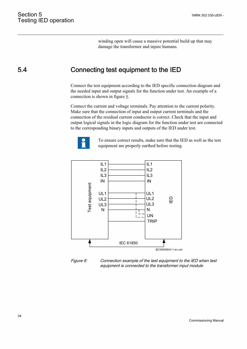
Connect the test equipment according to the IED specific connection diagram andthe needed input and output signals for the function under test. An example of aconnection is shown in figure 8.
Connect the current and voltage terminals. Pay attention to the current polarity.Make sure that the connection of input and output current terminals and theconnection of the residual current conductor is correct. Check that the input andoutput logical signals in the logic diagram for the function under test are connectedto the corresponding binary inputs and outputs of the IED under test.
To ensure correct results, make sure that the IED as well as the testequipment are properly earthed before testing.
IL1IL2IL3IN
UL1UL2UL3
N
IL1IL2IL3
UL1
IN
TRIP
Test
equ
ipm
ent
IEDUL2
UL3NUN
IEC 61850IEC09000643-1-en.vsd
IEC09000643 V1 EN
Figure 8: Connection example of the test equipment to the IED when testequipment is connected to the transformer input module
Section 5 1MRK 502 035-UEN -Testing IED operation
34Commissioning Manual
5.5 Releasing the function to be tested
Release or unblock the function to be tested. This is done to ensure that only thefunction or the chain of functions to be tested are in operation and that otherfunctions are prevented from operating. Release the tested function(s) by settingthe corresponding Blocked parameter under Function test modes to No in the localHMI.
When testing a function in this blocking feature, remember that not only the actualfunction must be activated, but the whole sequence of interconnected functions(from measuring inputs to binary output contacts), including logic must beactivated. Before starting a new test mode session, scroll through every function toensure that only the function to be tested (and the interconnected ones) have theparameters Blocked and eventually EvDisable set to No and Yes respectively.Remember that a function is also blocked if the BLOCK input signal on thecorresponding function block is active, which depends on the configuration. Ensurethat the logical status of the BLOCK input signal is equal to 0 for the function to betested. Event function blocks can also be individually blocked to ensure that noevents are reported to a remote station during the test. This is done by setting theparameter EvDisable to Yes.
Any function is blocked if the corresponding setting in the localHMI under Main menu/Tests/Function test modes menu remainsOn, that is, the parameter Blocked is set to Yes and the parameterTestMode under Main menu/Tests/IED test mode remains active.All functions that were blocked or released in a previous test modesession, that is, the parameter Test mode is set to On, are reset whena new test mode session is started.
Procedure
1. Click the Function test modes menu.The Function test modes menu is located in the local HMI under Main menu/Tests/Function test modes.
2. Browse to the function instance that needs to be released.3. Set parameter Blocked for the selected function to No.
5.6 Verifying analog primary and secondarymeasurement
Verify that the connections are correct and that measuring and scaling is donecorrectly. This is done by injecting current and voltage to the IED.
1MRK 502 035-UEN - Section 5Testing IED operation
35Commissioning Manual
Apply input signals as needed according to the actual hardware andthe application configuration made in PCM600.
1. Inject a symmetrical three-phase voltage and current at rated value.2. Compare the injected value with the measured values.
The voltage and current phasor menu in the local HMI is located under Mainmenu/Measurements/Analog primary values and Main menu/Measurements/Analog secondary values.
3. Compare the frequency reading with the set frequency and the direction of thepower.The frequency and active power are located under Main menu/Tests/Function status/Monitoring/CVMMXN/1:CVMMXN/Outputs. Thennavigate to the bottom of the list to find the frequency.
Check both analog primary and secondary values, becausethen the CT and VT ratios entered into the IED are also checked.
These checks shall be repeated for Analog primary values.4. Inject an unsymmetrical three-phase voltage and current, to verify that phases
are correctly connected.
If some setting deviates, check the analog input settings under
Main menu/Configuration/Analog modules
Measured values such as current and voltages as well as active, reactive andapparent power, power factor phase angles as well as positive and negative andzero sequence currents and voltages are available in the local HMI under Mainmenu/Tests/Function status/Monitoring.
Navigate to the measurement function that contains the quantity to be checked.
Table 1: Measurement functions
Function Quantity DescriptionCMMXU IL1 to IL3 amplitude, range and angle
CMSQI 3I0; I1 and I2 amplitude, range and angle
CVMMXN S; P; Q; PF; Ilag; Ilead; U; I andf
amplitude, range and angle
VMMXU UL12 to UL31 i.e. phase-to-phase
amplitude, range and angle
VMSQI 3U0; U1 and U2 amplitude, range and angle
VNMMXU UL1 to UL3 i.e. phase-to-neutral amplitude, range and angle
Section 5 1MRK 502 035-UEN -Testing IED operation
36Commissioning Manual
Also the Signal Monitoring tool in PCM600 can be used to read the measuredvalues. In many cases it is more convenient to use PCM600 since, among manythings, reports on measured values can be exported from the Signal Monitoringtool to other tools (for example, MS Excel) for further analysis.
5.7 Testing protection functionality
Each protection function must be tested individually by secondary injection.
• Verify operating levels (trip) and timers.• Verify alarm and blocking signals.• Use the disturbance handling tool in PCM600 to evaluate that the protection
function has received the correct data and responded correctly (signaling andtiming).
• Use the event viewer tool in PCM600 to check that only expected events haveoccurred.
1MRK 502 035-UEN - Section 5Testing IED operation
37Commissioning Manual

38
Section 6 Testing functionality
6.1 Testing disturbance report
6.1.1 IntroductionThe following sub-functions are included in the disturbance report function:
• Disturbance recorder• Event list• Event recorder• Trip value recorder• Indications
If the disturbance report is set on, then its sub-functions are also set up and so it isnot possible to only switch these sub-functions off. The disturbance report functionis switched off (parameter Operation = Off) in PCM600 or the local HMI underMain menu/Settings/IED Settings/Monitoring/Disturbance report/1:DRPRDRE.
6.1.2 Disturbance report settingsWhen the IED is in test mode, the disturbance report can be made active orinactive. If the disturbance recorder is turned on during test mode, recordings willbe made. When test mode is switched off all recordings made during the testsession are cleared.
Setting OpModeTest for the control of the disturbance recorder during test modeare located on the local HMI under Main menu/Settings/IED Settings/Monitoring/Disturbance report/1:DRPRDRE.
6.2 Identifying the function to test in the technicalreference manual
Use the technical manual to identify function blocks, logic diagrams, input andoutput signals, setting parameters and technical data.
1MRK 502 035-UEN - Section 6Testing functionality
39Commissioning Manual
6.3 Testing differential protection functions
6.3.1 Transformer differential protection T3WPDIFPrepare the IED for verification of settings as outlined in 5.1 "Preparing the IED toverify settings".
Values of the logical signals for T3WPDIF are available on the local HMI underMain menu/Tests/Function status/Differential/T3WPDIF(87T,Id)/1:T3WPDIF. The Signal Monitoring in PCM600 shows the same signals that areavailable on the local HMI.
6.3.1.1 Verifying the settings
1. Go to Main menu/Test/Function test modes/Differential protection andmake sure that the restricted earth fault protection, low impedance functionREFPDIF is set to Off and that the four step residual overcurrent functionEF4PTOC under Main menu/Test/Function test modes/Current protectionis set to Off, since they are configured to the same current transformer inputsas the transformer differential protection. Make sure that the transformerdifferential functions T2WPDIF or T3WPDIF are unblocked.
2. Connect the test set for injection of three-phase currents to the currentterminals of the IED, which are connected to the CTs on the HV side of thepower transformer.
3. Increase the current in phase L1 until the protection function operates andnote the operating current.
4. Check that trip and alarm contacts operate according to the configuration logic.5. Decrease the current slowly from operate value and note the reset value.
Depending of the power transformer vector group (Yd and so on), the single-phase injection current will be different for a factor k from the three-phasestart, see step 7. This factor k can have one of the following three values: 1,00or 1,50 or 1,732.
6. Check in the same way the function by injecting current in phases L2 and L3respectively. Phase L2 and L3 start shall be the same as for phase L1.
7. Inject a symmetrical three-phase current and note the operate value.8. Connect the timer and set the current to twice the operate value.9. Switch on the current and note the operate time.10. Check in the same way the functioning of the measuring circuits connected to
the CTs on the LV side and other current inputs to the transformer differentialprotection.
11. Finally check that trip information is stored in the event menu.12. If available on the test set a second harmonic current of about 20% (assumes
15% setting on I1/I2ratio parameter) can be added to the fundamental tone inphase L1. Increase the current in phase L1 above the start value measured instep 6. Repeat test with current injection in phases L2 and L3 respectively.
Section 6 1MRK 502 035-UEN -Testing functionality
40Commissioning Manual
Note that during this test setting SOTFMode must be set to Off.
The balancing of currents flowing into and out of the differential zone istypically checked by primary testing when suitable supply facilities exist onsite.Fifth harmonic blocking can be tested in a similar way. Note, the blockinglevel for the fifth harmonic is 10% higher than the I5/I1Ratio setting.
6.3.1.2 Completing the test
Continue to test another function or end the testing by setting the parameterTestMode to Off under Main menu/Tests/IED test mode/1:TESTMODE. Ifanother function is tested, then set the parameter Blocked to No under Main menu/Tests/Function test modes/Differential/T3WPDIF(87T,Id)/1:T3WPDIF for thefunction, or for each individual function in a chain, to be tested next. Remember toset the parameter Blocked to Yes, for each individual function that has been tested.
6.3.2 High impedance differential protection HZPDIFPrepare the IED for verification of settings as outlined in 5.1 "Preparing the IED toverify settings".
Values of the logical signals for HZPDIF are available on the local HMI underMain menu/Tests/Function status/Differential/HZPDIF(87,IdN)/X:HZPDIF.The Signal Monitoring in PCM600 shows the same signals that are available on thelocal HMI.
6.3.2.1 Verifying the settings
1. Connect single-phase or three-phase test set to inject the operating voltage.The injection shall be on the primary side of the stabilizing resistor.
As the operating voltage is adjusted on the stabilizing resistorand with the setting of the resistor value in the function this isessential for the measurement of the expected value. Normallya slightly higher operating value is no problem as thesensitivity is not influenced much.
2. Connect the trip contact to the test set to stop the test set for measurement oftrip times below.
3. Increase the voltage and make note of the operate value U>Trip. This is donewith manual test and without trip of the test set.
4. Reduce the voltage slowly and make note of the reset value. The reset valuemust be high for this function.
1MRK 502 035-UEN - Section 6Testing functionality
41Commissioning Manual
5. Check the operating time by injecting a voltage corresponding to 1.2 ·U>Trip level. Make note of the measured trip time.
6. If required, verify the trip time at another voltage. Normally 2 · U>Trip isselected.
7. If used, measure the alarm level operating value. Increase the voltage andmake note of the operate value U>Alarm. This is done with manual test andwithout trip of the test set.
8. Measure the operating time on the alarm output by connecting the stop of thetest set to an output from tAlarm. Inject a voltage 1.2 · U>Alarm and measurethe alarm time.
9. Check that trip and alarm outputs operate accordingly to the configuration logic.10. Finally check that start and alarm information is stored in the event menu and
if a serial connection to the SA is available verify that the correct and only therequired signals are presented on the local HMI and on the SCADA system.
Information on how to use the event menu is found in the operator'smanual.
6.3.2.2 Completing the test
Continue to test another function or end the testing by setting the parameterTestMode to Off under Main menu/Tests/IED test mode/1:TESTMODE. Ifanother function is tested, then set the parameter Blocked to No under Main menu/Tests/Function test modes/Differential/HZPDIF(87,IdN)/X:HZPDIF for thefunction, or for each individual function in a chain, to be tested next. Remember toset the parameter Blocked to Yes, for each individual function that has been tested.
6.3.3 Generator differential protection GENPDIFPrepare the IED for verification of settings as outlined in 5.1 "Preparing the IED toverify settings".
Values of the logical signals for GENPDIF are available on the local HMI underMain menu/Tests/Function status/Differential/GENPDIF(87G,IdG)/1:GENPDIF. The Signal Monitoring in PCM600 shows the same signals that areavailable on the local HMI.
6.3.3.1 Verifying the settings
1. Go to Main menu/Test/Function test modes/Differential protection andmake sure all other functions, configured to the same current transformer
Section 6 1MRK 502 035-UEN -Testing functionality
42Commissioning Manual
inputs as the generator differential protection, are set off. Make sure that thegenerator differential function is unblocked.
2. Connect the test set for injection of three-phase current to the current IEDs,which are connected to the CTs on the HV side of the generator.
3. Increase the current in phase L1 until the protection function operates andnote the operating current.
4. Check that trip and alarm contacts operate according to the configuration logic.5. Decrease the current slowly from operate value and note the reset value.6. Check in the same way the function by injecting current in phases L2 and L3.7. Inject a symmetrical three-phase current and note the operate value.8. Connect the timer and set the current to twice the operate value.9. Switch on the current and note the operate time.10. Check in the same way the functioning of the measuring circuits connected to
the CTs on the neutral point side of the generator.11. Finally check that trip information is stored in the event menu.
Information on how to use the event menu is found in theoperator’s manual.
12. If available on the test set a second-harmonic current of about 20% (assumes15% setting on I1/I2 ratio parameter) can be added to the fundamental tone inphase L1. Increase the current in phase L1 above the start value measured instep 3. Repeat test with current injection in phases L2 and L3 respectively.Fifth-harmonic blocking can be tested in a similar way.The balancing of currents flowing into and out of the differential zone istypically checked by primary testing.
6.3.3.2 Completing the test
Continue to test another function or end the testing by setting the parameterTestMode to Off under Main menu/Tests/IED test mode/1:TESTMODE. Ifanother function is tested, then set the parameter Blocked to No under Main menu/Tests/Function test modes/Differential/GENPDIF(87G,IdG)/1:GENPDIF forthe function, or for each individual function in a chain, to be tested next.Remember to set the parameter Blocked to Yes, for each individual function thathas been tested.
6.4 Testing impedance protection functions
6.4.1 Underimpedance protection for generators andtransformers ZGPDIS
Values of the logical signals for ZGPDIS are available on the local HMI underMain menu/Tests/Function status/Impedance/ZGPDIS(21G,Z<)/1:ZGPDIS.
1MRK 502 035-UEN - Section 6Testing functionality
43Commissioning Manual
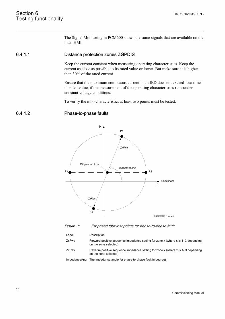
The Signal Monitoring in PCM600 shows the same signals that are available on thelocal HMI.
6.4.1.1 Distance protection zones ZGPDIS
Keep the current constant when measuring operating characteristics. Keep thecurrent as close as possible to its rated value or lower. But make sure it is higherthan 30% of the rated current.
Ensure that the maximum continuous current in an IED does not exceed four timesits rated value, if the measurement of the operating characteristics runs underconstant voltage conditions.
To verify the mho characteristic, at least two points must be tested.
6.4.1.2 Phase-to-phase faults
jX
ROhm/phase
ImpedanceAng
ZxFwd
ZxRev
P1
P2P3
P4
Midpoint of circle
IEC09000173_1_en.vsd
IEC09000173 V1 EN
Figure 9: Proposed four test points for phase-to-phase fault
Label Description
ZxFwd Forward positive sequence impedance setting for zone x (where x is 1- 3 dependingon the zone selected).
ZxRev Reverse positive sequence impedance setting for zone x (where x is 1- 3 dependingon the zone selected).
ImpedanceAng The Impedance angle for phase-to-phase fault in degrees.
Section 6 1MRK 502 035-UEN -Testing functionality
44Commissioning Manual
Table 2: Test points for phase-to-phase
Testpoints
X R
P1 ZxFwd · sin(ImpedanceAng) ZxFwd · cos(ImpedanceAng)
P2 (ZxFwd-ZxRev)/2 · sin(ImpedanceAng) ZxFwd/2 · (1+cos(ImpedanceAng)+ ZxRev/2 · (1-cos(ImpedanceAng)
P3 (ZxFwd-ZxRev)/2 · sin(ImpedanceAng) -ZxFwd/2 · (1-cos(ImpedanceAng) -ZxRev/2 ·(1+cos(ImpedanceAng)
P4 -ZxRev · sin(ImpedanceAng) -ZxRev · cos(ImpedanceAng)
Change the magnitude and angle of phase-to-phase voltage to achieve impedancesat test points p1, p2 and p3. For each test point, observe that the output signals,START and STZx are activated where x refers to the actual phase to be tested.After the timer tZx (where x is 1-3 depending on selected zone) for the actual zonehas elapsed, also the signals TRIP and TRZx (where x is 1-3 depending on selectedzone) shall be activated.
6.4.2 Loss of excitation LEXPDISPrepare the IED for verification of settings as outlined in 5.1 "Preparing the IED toverify settings".
Values of the logical signals for LEXPDIS are available on the local HMI underMain menu/Tests/Function status/Impedance/LEXPDIS(40)/1:LEXPDIS. TheSignal Monitoring in PCM600 shows the same signals that are available on thelocal HMI.
6.4.2.1 Verifying the settings
The test is done by means of injection of three phase current and three phasevoltage from a modern test device. This test device shall be able to give voltageand current corresponding to the set apparent impedance.
1. Feed the IED with current and voltage corresponding to the apparentimpedance: Test #1, as shown in figure 10. Read the analog outputs for R andX and check that this reading corresponds to the injected impedance. No startor trip signals shall be activated.
2. Feed the IED with current and voltage corresponding to the apparentimpedance: Test #2, as shown in figure 10. Read the analog outputs for R andX and check that this reading corresponds to the injected impedance. No startor trip signals shall be activated.
3. Feed the IED with current and voltage corresponding to the apparentimpedance: Test #3, as shown in figure 10. Read the analog outputs for R andX and check that this reading corresponds to the injected impedance. Thesignals START and STZ2 shall be activated instantaneously and the signalsTRIP and TRZ2 shall be activated after the set delay tZ2.
1MRK 502 035-UEN - Section 6Testing functionality
45Commissioning Manual
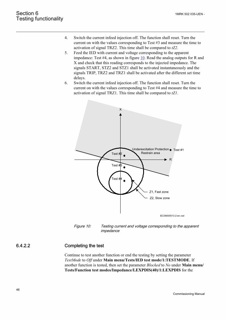
4. Switch the current infeed injection off. The function shall reset. Turn thecurrent on with the values corresponding to Test #3 and measure the time toactivation of signal TRZ2. This time shall be compared to tZ2.
5. Feed the IED with current and voltage corresponding to the apparentimpedance: Test #4, as shown in figure 10. Read the analog outputs for R andX and check that this reading corresponds to the injected impedance. Thesignals START, STZ2 and STZ1 shall be activated instantaneously and thesignals TRIP, TRZ2 and TRZ1 shall be activated after the different set timedelays.
6. Switch the current infeed injection off. The function shall reset. Turn thecurrent on with the values corresponding to Test #4 and measure the time toactivation of signal TRZ1. This time shall be compared to tZ1.
IEC06000513-2-en.vsd
R
X
Underexcitation Protection Restrain area
Z1, Fast zone
Z2, Slow zone
Test #1Test #2
Test #3
Test #4
IEC06000513 V2 EN
Figure 10: Testing current and voltage corresponding to the apparentimpedance
6.4.2.2 Completing the test
Continue to test another function or end the testing by setting the parameterTestMode to Off under Main menu/Tests/IED test mode/1:TESTMODE. Ifanother function is tested, then set the parameter Blocked to No under Main menu/Tests/Function test modes/Impedance/LEXPDIS(40)/1:LEXPDIS for the
Section 6 1MRK 502 035-UEN -Testing functionality
46Commissioning Manual
function, or for each individual function in a chain, to be tested next. Remember toset the parameter Blocked to Yes, for each individual function that has been tested.
6.4.3 Out-of-step OOSPPAMPrepare the IED for verification of settings as outlined in 5.1 "Preparing the IED toverify settings".
Values of the logical signals for OOSPPAM are available on the local HMI underMain menu/Tests/Function status/Impedance/OOSPPAM(78)/1:OOSPPAM.The Signal Monitoring in PCM600 shows the same signals that are available on thelocal HMI.
6.4.3.1 Verifying the settings
The commissioning procedure requires only one calculation and it must be donewhen all the settings have already been determined. The procedure is described inthe section Setting guidelines for the Out-of-step protection function.
Suppose that the voltages, the currents and the impedances ForwardR, ForwardX,ReverseR and ReverseX are equal to those in the example as described in the Figure6 in the section Setting guidelines for the Out-of-step protection function.
1. Calculate the magnitude of a fundamental frequency current I that results inthe measured reactance ForwardX, as shown in point A in Figure 11.
I A U ForwardX
I A kV Ohm
I A
gen[ ] =
[ ] =
[ ] =
/ /
. / / .
3
13 8 3 0 565
14107
IECEQUATION2321 V1 EN (Equation 1)2. Three symmetrical fundamental frequency phase voltages must be fed to IED,
with magnitudes proportional to Ugen / √(3), that is, taking into the account theactual PT ratio in the IED. If three symmetrical fundamental frequencycurrents, proportional to I = 14107 A, that is, taking into the account the CTratio, are fed to the IED, and they all lag their phase voltages by 90 electricaldegrees, OOSPPAM function must measure a reactance equal to ForwardX,that is, 58.38 percent of Zbase, corresponding to 0.565 Ohm. This reactance isconstant and stationary, as shown in point A in Figure 11. The voltages and thecurrents must be programmed for a signal generator, for example, Omicron.Voltages (instantaneous values) of the fundamental frequency, that is, 50 Hz or60 Hz, must be as follows. Example for fundamental frequency 50 Hz:
u U tL phase1 2 2 50 0= ⋅ ⋅ ⋅ ⋅ ⋅( )sin .π
IECEQUATION2328 V1 EN (Equation 2)
u U tL phase2 2 2 50 0 2 3= ⋅ ⋅ ⋅ ⋅ ⋅ − ⋅( )sin . /π π
IECEQUATION2329 V1 EN (Equation 3)
1MRK 502 035-UEN - Section 6Testing functionality
47Commissioning Manual
u U tL phase3 2 2 50 0 4 3= ⋅ ⋅ ⋅ ⋅ − ⋅( )sin . /π π
IECEQUATION2330 V1 EN (Equation 4)
Where Uphase = Ugen / √(3) = 13800 V / √(3) = 7967.4 Volts. The actual PTratio must be applied to this primary value of the phase voltage, so that theactual value of the secondary input voltage applied to IED can be calculated.The three symmetrical currents of the fundamental frequency, 50 Hz (or 60Hz), must be as follows:
i I tL1 2 2 50 0 2= ⋅ ⋅ ⋅ ⋅ ⋅ −( )sin . /π π
IECEQUATION2325 V1 EN (Equation 5)
i I tL2 2 2 50 0 2 2 3= ⋅ ⋅ ⋅ ⋅ ⋅ − − ⋅( )sin . / /π π π
IECEQUATION2326 V1 EN (Equation 6)
i I tL3 2 2 50 0 2 4 3= ⋅ ⋅ ⋅ ⋅ ⋅ − − ⋅( )sin . / /π π π
IECEQUATION2327 V1 EN (Equation 7)
Where I = Ugen / √(3) / ForwardX = 14107 A. The actual CT ratio must beapplied to this primary current so that correct value of the secondary injectedcurrent can be calculated.Expected result: The function must measure a reactance X = ForwardX =58.38 percent of Zbase, which corresponds to 0.565 Ohm. The TRIP signalmust remain FALSE (0).
3. In the last step of the commissioning procedure, apart from the fundamentalfrequency current described above, another current component must beinjected, with a frequency equal to the nominal frequency ± 1.000 Hz. Fornominal frequency 50 Hz, first 49. 000 Hz and then 51.000 Hz. The magnitudeof this additional current component must be 0.9 times current I. If thesymmetrical additional current component in all three phases has 49.000 Hz,the trajectory of the complex impedance has to be exactly as illustrated inFigure 11. The complex impedance Z(R, X) travels from the right side towardsthe left side, as shown in Figure 11. The Boolean output signal GENMODEmust be set to TRUE (1) as shown in Figure 12. If the X-line is set in a way, sothat the zone 2 begins on the power transformer HV-side terminals, asdescribed in Figure 11, then all the pole slips occur in zone 2, and this can beobserved as the Boolean output TRIPZ2, which must be periodically (with 1Hz) set to TRUE (1), and then reset to FALSE (0). The output trip must be setto TRUE (1) and persist at that value under this test. If the additionalcomponent of the current is 51.000 Hz, the complex impedance Z(R, X)travels from the left side towards the right side and the Boolean output signalMOTMODE has to be set to TRUE (1). The rest of the signals must be asunder the 49 Hz test.If a signal generator (for example, Omicron) is to be programmed for theabove description that is, commissioning test, then the currents must be asfollows (while the voltages remain as in step 2):Currents (instantaneous values) with two components, of which one has thefundamental frequency, that is, 50 Hz or 60 Hz, must be as follows. Examplefor fundamental frequency 50 Hz:
Section 6 1MRK 502 035-UEN -Testing functionality
48Commissioning Manual
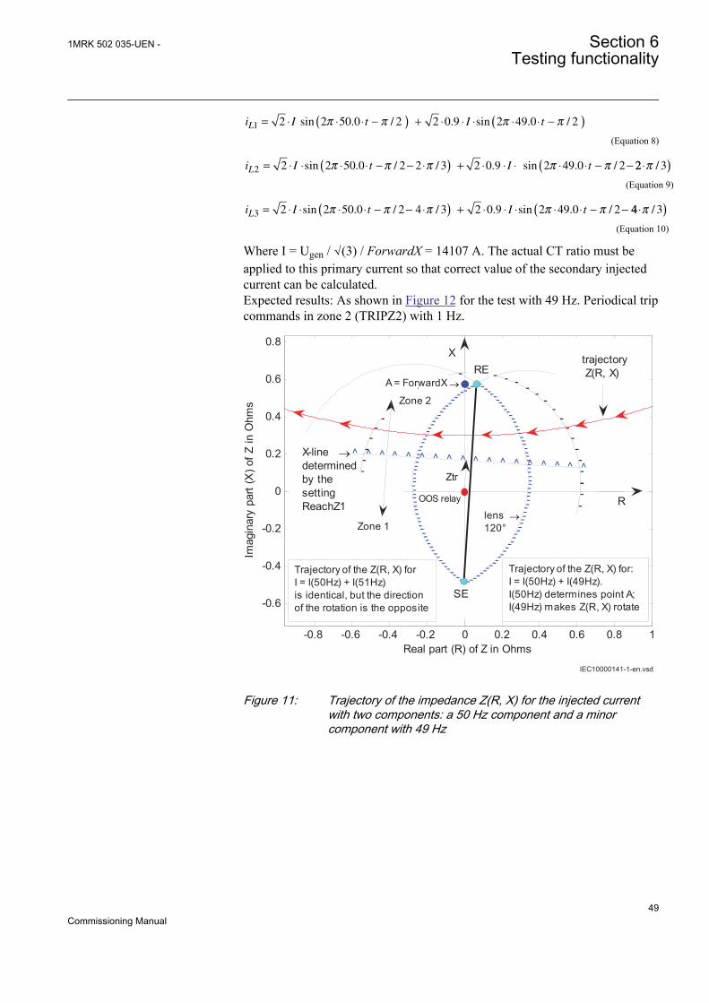
i I t I tL1 2 2 50 0 2 2 0 9 2 49 0 2= ⋅ ⋅ ⋅ −( ) + ⋅ ⋅ ⋅ ⋅ ⋅ −( )sin . / . sin . /π π π π
IECEQUATION2322 V1 EN (Equation 8)
i I t I tL2 2 2 50 0 2 2 3 2 0 9 2 49 0 2= ⋅ ⋅ ⋅ ⋅ − − ⋅( ) + ⋅ ⋅ ⋅ ⋅ ⋅ − −sin . / / . sin . /π π π π π 22 3⋅( )π /
IECEQUATION2323 V1 EN (Equation 9)
i I t I tL3 2 2 50 0 2 4 3 2 0 9 2 49 0 2= ⋅ ⋅ ⋅ ⋅ − − ⋅( ) + ⋅ ⋅ ⋅ ⋅ ⋅ − −sin . / / . sin . /π π π π π 44 3⋅( )π /
IECEQUATION2324 V1 EN (Equation 10)
Where I = Ugen / √(3) / ForwardX = 14107 A. The actual CT ratio must beapplied to this primary current so that correct value of the secondary injectedcurrent can be calculated.Expected results: As shown in Figure 12 for the test with 49 Hz. Periodical tripcommands in zone 2 (TRIPZ2) with 1 Hz.
IEC10000141-1-en.vsd
-0.8 -0.6 -0.4 -0.2 0 0.2 0.4 0.6 0.8 1
-0.6
-0.4
-0.2
0
0.2
0.4
0.6
0.8
-------------------------------------------------------------------
------
-----
------------------------------
------
------
Real part (R) of Z in Ohms
Imag
inar
y pa
rt (X
) of Z
in O
hms
^ ^ ^ ^ ^ ^ ^ ^ ^ ^ ^ ^ ^ ^ ^ ^ ^ ^---
--
--
----------------
--
--
---- -
--
--
--
--
--------------
--
--
----
trajectory Z(R, X)
R
Trajectory of the Z(R, X) for:I = I(50Hz) + I(49Hz).I(50Hz) determines point A;I(49Hz) makes Z(R, X) rotate
SE
Zone 1
Trajectory of the Z(R, X) forI = I(50Hz) + I(51Hz)is identical, but the directionof the rotation is the opposite
OOS relay
Ztr
lens →120°
X-line →determinedby the settingReachZ1
REA = ForwardX →
Zone 2
Zone 1
X
IEC10000141 V1 EN
Figure 11: Trajectory of the impedance Z(R, X) for the injected currentwith two components: a 50 Hz component and a minorcomponent with 49 Hz
1MRK 502 035-UEN - Section 6Testing functionality
49Commissioning Manual
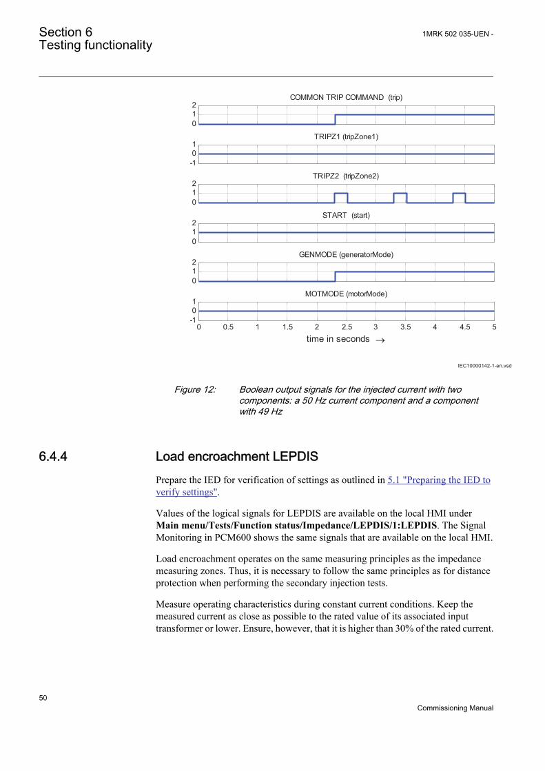
IEC10000142-1-en.vsd
012
COMMON TRIP COMMAND (trip)
-101
TRIPZ1 (tripZone1)
012
TRIPZ2 (tripZone2)
012
START (start)
012
GENMODE (generatorMode)
0 0.5 1 1.5 2 2.5 3 3.5 4 4.5 5-101
time in seconds →
MOTMODE (motorMode)
IEC10000142 V1 EN
Figure 12: Boolean output signals for the injected current with twocomponents: a 50 Hz current component and a componentwith 49 Hz
6.4.4 Load encroachment LEPDISPrepare the IED for verification of settings as outlined in 5.1 "Preparing the IED toverify settings".
Values of the logical signals for LEPDIS are available on the local HMI underMain menu/Tests/Function status/Impedance/LEPDIS/1:LEPDIS. The SignalMonitoring in PCM600 shows the same signals that are available on the local HMI.
Load encroachment operates on the same measuring principles as the impedancemeasuring zones. Thus, it is necessary to follow the same principles as for distanceprotection when performing the secondary injection tests.
Measure operating characteristics during constant current conditions. Keep themeasured current as close as possible to the rated value of its associated inputtransformer or lower. Ensure, however, that it is higher than 30% of the rated current.
Section 6 1MRK 502 035-UEN -Testing functionality
50Commissioning Manual
Ensure that the maximum continuous current of an IED does not exceed four timesits rated value, if the measurement of the operating characteristics runs underconstant voltage conditions.
6.4.4.1 Measuring the operate limit of set values
The load encroachment function has no outputs of its own. It canonly be checked together with the impedance function.
1. Supply the IED with healthy conditions for at least two seconds.2. Apply the fault condition and slowly decrease the measured impedance to
find the operate value for of the phase-to-earth and phase-to-phase loops.
6.4.4.2 Completing the test
Continue to test another function or end the testing by setting the parameterTestMode to Off under Main menu/Tests/IED test mode/1:TESTMODE. Ifanother function is tested, then set the parameter Blocked to No under Main menu/Tests/Function test modes/Impedance/LEPDIS/1:LEPDIS for the function, orfor each individual function in a chain, to be tested next. Remember to set theparameter Blocked to Yes, for each individual function that has been tested.
6.5 Testing current protection functions
6.5.1 Four step phase overcurrent protection OC4PTOCPrepare the IED for verification of settings as outlined in 5.1 "Preparing the IED toverify settings".
Values of the logical signals for OC4PTOC are available on the local HMI underMain menu/Tests/Function status/Current/OC4PTOC(51_67,4I>)/1:OC4PTOC. The Signal Monitoring in PCM600 shows the same signals that areavailable on the local HMI.
6.5.1.1 Verifying the settings
1. Connect the test set for appropriate current injection to the appropriate IEDphases.If there is any configuration logic that is used to enable or block any of thefour available overcurrent steps, make sure that the step under test is enabled,for example end fault protection.
1MRK 502 035-UEN - Section 6Testing functionality
51Commissioning Manual
Connect the symmetrical three-phase injection current into phases L1, L2 andL3.
2. Connect the test set for the appropriate three-phase voltage injection to theIED phases L1, L2 and L3. The protection shall be fed with a symmetrical three-phase voltage.
3. Set the injected polarizing voltage slightly larger than the set minimumpolarizing voltage (default is 5% of UBase) and set the injection current to lagthe appropriate voltage by an angle of 55° if forward directional function isselected.If 1 out of 3 currents for operation is chosen: The voltage angle of phase L1 isthe reference.The voltage angle of phase L1 is the reference.If reverse directional function is selected, set the injection current to lag thepolarizing voltage by an angle equal to 235° (equal to 55° + 180°).
4. Increase the injected current and note the operated value of the tested step ofthe function.
5. Decrease the current slowly and note the reset value.6. If the test has been performed by injection of current in phase L1, repeat the
test when injecting current into phases L2 and L3 with polarizing voltageconnected to phases L2 respectively L3 (1 out of 3 currents for operation).
7. If the test has been performed by injection of current in phases L1 – L2,repeat the test when injecting current into phases L2 – L3 and L3 – L1 withappropriate phase angle of injected currents.
8. Block higher set stages when testing lower set stages according to below.9. Connect a trip output contact to a timer.10. Set the injected current to 200% of the operate level of the tested stage,
switch on the current and check the time delay.For inverse time curves, check the operate time at a current equal to 110% ofthe operate current for txMin.
11. Check that all trip and start contacts operate according to the configuration(signal matrixes)
12. Reverse the direction of the injected current and check that the protectiondoes not operate.
13. Repeat the above described tests for the higher set stages.14. Finally check that start and trip information is stored in the event menu.
Check of the non-directional phase overcurrent function. Thisis done in principle as instructed above, without applying anypolarizing voltage.
6.5.1.2 Completing the test
Continue to test another function or end the testing by setting the parameterTestMode to Off under Main menu/Tests/IED test mode/1:TESTMODE. Ifanother function is tested, then set the parameter Blocked to No under Main menu/Tests/Function test modes/Current/OC4PTOC(51_67,4I>)/1:OC4PTOC forthe function, or for each individual function in a chain, to be tested next.
Section 6 1MRK 502 035-UEN -Testing functionality
52Commissioning Manual
Remember to set the parameter Blocked to Yes, for each individual function thathas been tested.
6.5.2 Four step residual overcurrent protection EF4PTOCPrepare the IED for verification of settings as outlined in 5.1 "Preparing the IED toverify settings".
Values of the logical signals for EF4PTOC are available on the local HMI underMain menu/Tests/Function status/Current/EF4PTOC(51N67N,4IN>)/X:EF4PTOC. The Signal Monitoring in PCM600 shows the same signals that areavailable on the local HMI.
6.5.2.1 Four step directional residual overcurrent protection
1. Connect the test set for single current injection to the appropriate IED terminals.Connect the injection current to terminals L1 and neutral, or to terminals Nand neutral.
2. Set the injected polarizing voltage slightly larger than the set minimumpolarizing voltage (default 1% of Ur) and set the injection current to lag thevoltage by an angle equal to the set reference characteristic angle (AngleRCA)if the forward directional function is selected.If reverse directional function is selected, set the injection current to lag thepolarizing voltage by an angle equal to RCA+ 180°.
3. Increase the injected current and note the value at which the studied step ofthe function operates.
4. Decrease the current slowly and note the reset value.5. If the test has been performed by injection of current in phase L1, repeat the
test when injecting current into terminals L2 and L3 with a polarizing voltageconnected to terminals L2 respectively L3.
6. Block lower set steps when testing higher set steps according to theinstructions that follow.
7. Connect a trip output contact to a timer.8. Set the injected current to 200% of the operate level of the tested step, switch
on the current and check the time delay.For inverse time curves, check the operate time at a current equal to 110% ofthe operate current for txMin.
9. Check that all trip and start contacts operate according to the configuration(signal matrixes)
10. Reverse the direction of the injected current and check that the step does notoperate.
11. Check that the protection does not operate when the polarizing voltage is zero.12. Repeat the above described tests for the higher set steps.13. Finally, check that start and trip information is stored in the event menu.
1MRK 502 035-UEN - Section 6Testing functionality
53Commissioning Manual
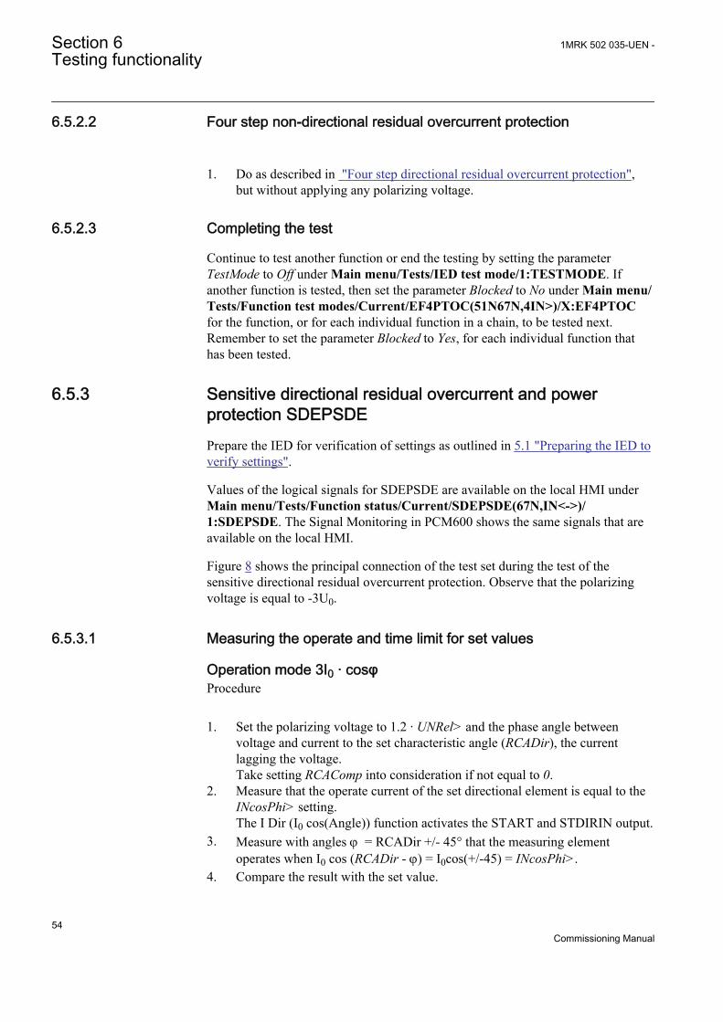
6.5.2.2 Four step non-directional residual overcurrent protection
1. Do as described in "Four step directional residual overcurrent protection",but without applying any polarizing voltage.
6.5.2.3 Completing the test
Continue to test another function or end the testing by setting the parameterTestMode to Off under Main menu/Tests/IED test mode/1:TESTMODE. Ifanother function is tested, then set the parameter Blocked to No under Main menu/Tests/Function test modes/Current/EF4PTOC(51N67N,4IN>)/X:EF4PTOCfor the function, or for each individual function in a chain, to be tested next.Remember to set the parameter Blocked to Yes, for each individual function thathas been tested.
6.5.3 Sensitive directional residual overcurrent and powerprotection SDEPSDEPrepare the IED for verification of settings as outlined in 5.1 "Preparing the IED toverify settings".
Values of the logical signals for SDEPSDE are available on the local HMI underMain menu/Tests/Function status/Current/SDEPSDE(67N,IN<->)/1:SDEPSDE. The Signal Monitoring in PCM600 shows the same signals that areavailable on the local HMI.
Figure 8 shows the principal connection of the test set during the test of thesensitive directional residual overcurrent protection. Observe that the polarizingvoltage is equal to -3U0.
6.5.3.1 Measuring the operate and time limit for set values
Operation mode 3I0 · cosφProcedure
1. Set the polarizing voltage to 1.2 · UNRel> and the phase angle betweenvoltage and current to the set characteristic angle (RCADir), the currentlagging the voltage.Take setting RCAComp into consideration if not equal to 0.
2. Measure that the operate current of the set directional element is equal to theINcosPhi> setting.The I Dir (I0 cos(Angle)) function activates the START and STDIRIN output.
3. Measure with angles j = RCADir +/- 45° that the measuring elementoperates when I0 cos (RCADir - j) = I0cos(+/-45) = INcosPhi>.
4. Compare the result with the set value.
Section 6 1MRK 502 035-UEN -Testing functionality
54Commissioning Manual
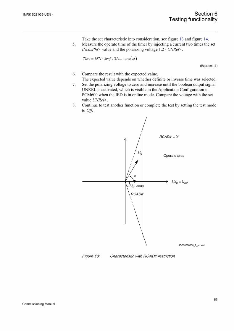
Take the set characteristic into consideration, see figure 13 and figure 14.5. Measure the operate time of the timer by injecting a current two times the set
INcosPhi> value and the polarizing voltage 1.2 · UNRel>.
( )0/ 3 costestTinv kSN Sref I j= × ×
IECEQUATION2402 V1 EN (Equation 11)
6. Compare the result with the expected value.The expected value depends on whether definite or inverse time was selected.
7. Set the polarizing voltage to zero and increase until the boolean output signalUNREL is activated, which is visible in the Application Configuration inPCM600 when the IED is in online mode. Compare the voltage with the setvalue UNRel>.
8. Continue to test another function or complete the test by setting the test modeto Off.
Operate area
ROADir
IEC06000650_2_en.vsd
= o0RCADir
03I
j
03 × jI cos- =03 refU U
IEC06000650 V2 EN
Figure 13: Characteristic with ROADir restriction
1MRK 502 035-UEN - Section 6Testing functionality
55Commissioning Manual
-3U0=Uref
Operate area
Instrumenttransformerangle error
3I0 (prim) 3I0 (to prot)
a
Characteristic afterangle compensation
RCAcomp
en06000651.vsd
RCADir = 0º
IEC06000651 V2 EN
Figure 14: Explanation of RCAcomp
Operation mode 3I0 · 3U0 · cosφ
1. Set the polarizing voltage to 1.2 · UNRel> and the phase angle betweenvoltage and current to the set characteristic angle (RCADir), the currentlagging the voltage.
2. Measure that the operate power is equal to the SN> setting for the setdirectional element.Note that for operation, both the injected current and voltage must be greaterthan the set values INRel> and UNRel> respectively.The function activates the START and STDIRIN outputs.
3. Measure with angles j = RCADir +/- 45° that the measuring element operateswhen 3I0 · 3U0 · cos (RCADir - j) = 3I0 · 3U0 · cos(+/-45) = SN>.
4. Compare the result with the set value. Take the set characteristic intoconsideration, see figure 13 and figure 14.
5. Measure the operate time of the timer by injecting 1.2 · UNRel> and a currentto get two times the set SN> operate value.
Section 6 1MRK 502 035-UEN -Testing functionality
56Commissioning Manual
( )0 0/ 3 3 costest testTinv kSN Sref I U j= × × ×
IECEQUATION2403 V1 EN (Equation 12)
6. Compare the result with the expected value.The expected value depends on whether definite or inverse time was selected.
7. Continue to test another function or complete the test by setting the test modeto Off.
Operation mode 3I0 and φ
1. Set the polarizing voltage to 1.2 · UNRel> and the phase angle betweenvoltage and current to the set characteristic angle (RCADir), the currentlagging the voltage.
2. Measure that the operate power is equal to the INDir> setting for the setdirectional element.
Note that for operation, both the injected current and voltagemust be greater than the set values INRel> and UNRel>respectively.
The function activates the START and STDIRIN output.3. Measure with angles j around RCADir +/- ROADir.4. Compare the result with the set values, refer to figure 15 for example
characteristic.5. Measure the operate time of the timer by injecting a current to get two times
the set SN> operate value.
( )0 0/ 3 3 costest testTinv kSN Sref I U j= × × ×
IECEQUATION2403 V1 EN (Equation 13)
6. Compare the result with the expected value.The expected value depends on whether definite or inverse time was selected.
7. Continue to test another function or complete the test by setting the test modeto Off.
1MRK 502 035-UEN - Section 6Testing functionality
57Commissioning Manual

-3U08080
Operate area
3I0
en06000652.vsd
RCADir = 0º
ROADir = 80º
IEC06000652 V2 EN
Figure 15: Example characteristic
Non-directional earth fault current protectionProcedure
1. Measure that the operate current is equal to the INNonDir> setting.The function activates the START and STDIRIN output.
2. Measure the operate time of the timer by injecting a current to get two timesthe set INNonDir> operate value.
3. Compare the result with the expected value.The expected value depends on whether definite time tINNonDir or inversetime was selected.
4. Continue to test another function or complete the test by setting the test modeto Off.
Residual overvoltage release and protectionProcedure
1. Measure that the operate voltage is equal to the UN> setting.The function activates the START and STUN signals.
2. Measure the operate time by injecting a voltage 1.2 timers set UN> operatevalue.
3. Compare the result with the set tUN operate value.4. Inject a voltage 0.8 · UNRel> and a current high enough to operate the
directional function at the chosen angle.5. Increase the voltage until the directional function is released.6. Compare the measured value with the set UNRel> operate value.
Section 6 1MRK 502 035-UEN -Testing functionality
58Commissioning Manual
6.5.3.2 Completing the test
Continue to test another function or end the testing by setting the parameterTestMode to Off under Main menu/Tests/IED test mode/1:TESTMODE. Ifanother function is tested, then set the parameter Blocked to No under Main menu/Tests/Function test modes/Current/SDEPSDE(67N,IN<->)/1:SDEPSDE for thefunction, or for each individual function in a chain, to be tested next. Remember toset the parameter Blocked to Yes, for each individual function that has been tested.
6.5.4 Thermal overload protection, two time constants TRPTTRPrepare the IED for verification of settings as outlined in 5.1 "Preparing the IED toverify settings".
Values of the logical signals for TRPTTR are available on the local HMI underMain menu/Tests/Function status/Current/TRPTTR(49,T>)/X:TRPTTR. TheSignal Monitoring in PCM600 shows the same signals that are available on thelocal HMI.
6.5.4.1 Checking operate and reset values
1. Connect symmetrical three-phase currents to the appropriate current terminalsof the IED.
2. Set the Time constant 1 (Tau1) and Time Constant 2 (Tau2) temporarily to 1minute.
3. Set the three-phase injection currents slightly lower than the set operate valueof stage IBase1, increase the current in phase L1 until stage IBase1 operatesand note the operate value.
Observe the maximum permitted overloading of the currentcircuits in the IED.
4. Decrease the current slowly and note the reset value.
Check in the same way as the operate and reset values of IBase1 for phasesL2 and L3.
5. Activate the digital input for cooling input signal to switch over to basecurrent IBase2.
6. Check for all three phases the operate and reset values for IBase2 in the sameway as described above for stage IBase1
7. Deactivate the digital input signal for stage IBase2.8. Set the time constant for IBase1 in accordance with the setting plan.9. Set the injection current for phase L1 to 1.50 · IBase1.10. Connect a trip output contact to the timer and monitor the output of contacts
ALARM1 and ALARM2 to digital inputs in test equipment.
1MRK 502 035-UEN - Section 6Testing functionality
59Commissioning Manual
Read the heat content in the thermal protection from the local HMI and waituntil the content is zero.
11. Switch on the injection current and check that ALARM1 and ALARM2contacts operate at the set percentage level and that the operate time fortripping is in accordance with the set Time Constant 1 (Tau1).With setting Itr = 101%IBase1 and injection current 1.50 · IBase1, the triptime from zero content in the memory shall be 0.60 · Time Constant 1 (Tau1).
12. Check that all trip and alarm contacts operate according to the configurationlogic.
13. Switch off the injection current and check from the service menu readings ofthermal status and LOCKOUT that the lockout resets at the set percentage ofheat content.
14. Activate the digital input for cooling input signal to switch over to basecurrent IBase2.Wait 5 minutes to empty the thermal memory and set Time Constant 2 (Tau2)in accordance with the setting plan.
15. Test with injection current 1.50 · IBase2 the thermal alarm level, the operatetime for tripping and the lockout reset in the same way as described for stageIBase1.
16. Finally check that start and trip information is stored in the event menu.
6.5.4.2 Completing the test
Continue to test another function or end the testing by setting the parameterTestMode to Off under Main menu/Tests/IED test mode/1:TESTMODE. Ifanother function is tested, then set the parameter Blocked to No under Main menu/Tests/Function test modes/Current/TRPTTR(49,T>)/X:TRPTTR for thefunction, or for each individual function in a chain, to be tested next. Remember toset the parameter Blocked to Yes, for each individual function that has been tested.
6.5.5 Breaker failure protection CCRBRFPrepare the IED for verification of settings as outlined in 5.1 "Preparing the IED toverify settings".
Values of the logical signals for CCRBRF are available on the local HMI underMain menu/Tests/Function status/Current/CCRBRF(50BF)/1:CCRBRF. TheSignal Monitoring in PCM600 shows the same signals that are available on thelocal HMI.
The Breaker failure protection function CCRBRF should normally be tested inconjunction with some other function that provides a start signal. An externalSTART signal can also be used.
To verify the settings in the most common back-up trip mode 1 out of 3, it issufficient to test phase-to-earth faults.
At mode 2 out of 4 the phase current setting, IP> can be checked by single-phaseinjection where the return current is connected to the summated current input. The
Section 6 1MRK 502 035-UEN -Testing functionality
60Commissioning Manual
value of residual (earth fault) current IN set lower than IP> is easiest checked in back-up trip mode 1 out of 4.
6.5.5.1 Checking the phase current operate value, IP>
Check the current level IP> where setting FunctionMode=Current and settingBuTripMode=1 out of 3 or 2 out of 4 as set under Main menu/Settings/IEDSettings/Current/CCRBRF(50BF)/1:CCRBRF.
1. Apply the fault condition, including START of CCRBRF, with a currentbelow set IP>.
2. Repeat the fault condition and increase the current in steps until a trip occurs.3. Compare the result with the set IP>.4. Disconnect AC and START input signals.
Note! If NoI>check or Retrip off is set, only back-up trip canbe used to check set IP>.
6.5.5.2 Checking the residual (earth fault) current operate value IN> setbelow IP>
Check the low set IN> current where setting FunctionMode = Current and settingBuTripMode = 1 out of 4 as set under Main menu/Settings/IED Settings/Current/CCRBRF(50BF)/1:CCRBRF.
1. Apply the fault condition, including START of CCRBRF, with a current justbelow set IN>Pickup_N.
2. Repeat the fault condition and increase the current in steps until trip appears.3. Compare the result with the set IN>.4. Disconnect AC and START input signals.
6.5.5.3 Checking the re-trip and back-up times
The check of the set times can be made in connection with the check of operatevalues above.
Choose the applicable function and trip mode, such as FunctionMode = Currentand setting RetripMode = No CBPos. Check as set under Main menu/Settings/IED Settings/Current/CCRBRF(50BF)/1:CCRBRF.
1. Apply the fault condition, including start of CCRBRF, well above the setcurrent value. Measure time from START of CCRBRF.
2. Check the re-trip t1 and back-up trip times t2.3. Disconnect AC and START input signals.
1MRK 502 035-UEN - Section 6Testing functionality
61Commissioning Manual
6.5.5.4 Verifying the re-trip mode
Choose the mode below, which corresponds to the actual case.
In the cases below it is assumed that FunctionMode = Current as set under Mainmenu/Settings/IED Settings/Current/CCRBRF(50BF)/1:CCRBRF.
Checking the case without re-trip, RetripMode = Retrip Off
1. Set RetripMode = Retrip Off.2. Apply the fault condition, including start of CCRBRF, well above the set
current value.3. Verify that no re-trip, but back-up trip is achieved after set time.4. Disconnect AC and START input signals.
Checking the re-trip with current check, RetripMode = CB Pos Check
1. Set RetripMode = CB Pos Check.2. Apply the fault condition, including start of CCRBRF, well above the set
current value.3. Verify that re-trip is achieved after set time t1 and back-up trip after time t24. Apply the fault condition, including start of CCRBRF, with current below set
current value.5. Verify that no re-trip, and no back-up trip is obtained.6. Disconnect AC and START input signals.
Checking re-trip without current check, RetripMode = No CBPos Check
1. Set RetripMode = No CBPos Check.2. Apply the fault condition, including start of CCRBRF, without any current.3. Verify that re-trip is achieved after set time t1, and back-up trip after time t2.4. Apply the fault condition, including start of CCRBRF, with current below set
current value.5. Verify that re-trip is achieved after set time t1, but no back-up trip is obtained.6. Disconnect AC and START input signals.
6.5.5.5 Verifying the back-up trip mode
In the cases below it is assumed that FunctionMode = Current is selected.
Checking that back-up tripping is not achieved at normal CB trippingUse the actual tripping modes. The case below applies to re-trip with current check.
Section 6 1MRK 502 035-UEN -Testing functionality
62Commissioning Manual
1. Apply the fault condition, including start of CCRBRF, with phase currentwell above set value IP.
2. Arrange switching the current off, with a margin before back-up trip time, t2.It may be made at issue of re-trip command.
3. Check that re-trip is achieved, if selected, but no back-up trip.4. Disconnect AC and START input signals.
The normal mode BuTripMode = 1 out of 3 should have been verified in the testsabove. In applicable cases the modes 1 out of 4 and 2 out of 4 can be checked.Choose the mode below, which corresponds to the actual case.
Checking the case BuTripMode = 1 out of 4It is assumed that the earth-fault current setting IN> is below phase current settingIP>.
1. Set BuTripMode = 1 out of 4.2. Apply the fault condition, including start of CCRBRF, with one-phase current
below set IP> but above IN>. The residual earth fault should then be aboveset IN>.
3. Verify that back-up trip is achieved after set time. If selected, re-trip shouldalso appear.
4. Disconnect AC and START input signals.
Checking the case BuTripMode = 2 out of 4The earth-fault current setting IN> may be equal to or below phase-current settingIP>.
1. Set BuTripMode = 2 out of 4.2. Apply the fault condition, including start of CCRBRF, with one-phase current
above set IP> and residual (earth fault) above set IN>. It can be obtained byapplying a single-phase current.
3. Verify that back-up trip is achieved after set time. If selected, re-trip shouldalso appear.
4. Apply the fault condition, including start of CCRBRF, with at least one-phasecurrent below set IP> and residual (earth fault) above set IN>. The currentmay be arranged by feeding three- (or two-) phase currents with equal phaseangle (I0-component) below IP>, but of such value that the residual (earthfault) current (3I0) will be above set value IN>.
5. Verify that back-up trip is not achieved.6. Disconnect AC and START input signals.
6.5.5.6 Verifying the case RetripMode = Contact
It is assumed that re-trip without current check is selected, RetripMode = Contact.
1MRK 502 035-UEN - Section 6Testing functionality
63Commissioning Manual
1. Set FunctionMode = Contact2. Apply input signal for CB closed to input CBCLDL1 (2 or 3)CBCLD3. Apply input signal, for start of CCRBRF. The value of current could be low.4. Verify that phase-selection re-trip and back-up trip are achieved after set times.5. Disconnect the start signal. Keep the CB closed signal.6. Apply input signal, for start of CCRBRF. The value of current could be low.7. Arrange disconnection of CB closed signal well before set back-up trip time
t2.8. Verify that back-up trip is not achieved.9. Disconnect injected AC and START input signals.
6.5.5.7 Verifying the function mode Current&Contact
To be made only when FunctionMode = Current&Contact is selected.
Checking the case with fault current above set value IP>The operation shall be as in FunctionMode = Current.
1. Set FunctionMode = Current&Contact.2. Leave the inputs for CB close inactivated. These signals should not influence.3. Apply the fault condition, including start of CCRBRF, with current above the
set IP> value.4. Check that the re-trip, if selected, and back-up trip commands are achieved.5. Disconnect injected AC and START input signals.
Checking the case with fault current below set value I>BlkContThe case shall simulate a case where the fault current is very low and operationwill depend on CB position signal from CB auxiliary contact. It is suggested that re-trip without current check is used, setting RetripMode = No CBPos Check.
1. Set FunctionMode = Current&Contact.2. Apply input signal for CB closed to relevant input or inputs CBCLDL1 (2 or 3)3. Apply the fault condition with input signal(s) for start of CCRBRF. The value
of current should be below the set value I>BlkCont4. Verify that phase-selection re-trip (if selected) and back-up trip are achieved
after set times. Failure to trip is simulated by keeping the signal(s) CB closedactivated.
5. Disconnect the AC and the START signal(s). Keep the CB closed signal(s).6. Apply the fault and the start again. The value of current should be below the
set value I>BlkCont.7. Arrange disconnection of BC closed signal(s) well before set back-up trip
time t2. It simulates a correct CB tripping.8. Verify that back-up trip is not achieved. Re-trip can appear for example, due
to selection “Re-trip without current check”.9. Disconnect injected AC and START input signals.
Section 6 1MRK 502 035-UEN -Testing functionality
64Commissioning Manual
6.5.5.8 Completing the test
Continue to test another function or end the testing by setting the parameterTestMode to Off under Main menu/Tests/IED test mode/1:TESTMODE. Ifanother function is tested, then set the parameter Blocked to No under Main menu/Tests/Function test modes/Current/CCRBRF(50BF)/X:CCRBRF for thefunction, or for each individual function in a chain, to be tested next. Remember toset the parameter Blocked to Yes, for each individual function that has been tested.
6.5.6 Pole discordance protection CCRPLDPrepare the IED for verification of settings as outlined in 5.1 "Preparing the IED toverify settings".
Values of the logical signals for CCRPLD are available on the local HMI underMain menu/Tests/Function status/Current/CCRPLD(52PD)/X:CCRPLD. TheSignal Monitoring in PCM600 shows the same signals that are available on thelocal HMI.
6.5.6.1 Verifying the settings
1. When CCRPLD is set for external, set setting ContSel to On under Mainmenu/Settings/IED Settings/Current/CCRPLD/1:CCRPLD to activate thelogic that detects pole discordance when external pole discordance signalingis used (input EXTPDIND) in the application configuration.
2. Activate the input EXTPDIND on CCRPLD function block, and measure theoperating time of CCRPLD.
3. Compare the measured time with the set value tTrip.4. Reset the EXTPDIND input.5. When CCRPLD is set for unsymmetrical current detection with CB
monitoring, set setting CurrSel under Main menu/Settings/IED Settings/Current/CCRPLD/1:CCRPLD to On.Use the TRIP signal from the configured binary output to stop the timer.
6. Repeat point 4 and 5 using OPENCMD instead of CLOSECMD. Set all threecurrents to 110% of CurrRelLevel. Activate CLOSECMD.NO TRIP signal should appear due to symmetrical condition.
6.5.6.2 Completing the test
Continue to test another function or end the testing by setting the parameterTestMode to Off under Main menu/Tests/IED test mode/1:TESTMODE. Ifanother function is tested, then set the parameter Blocked to No under Main menu/Tests/Function test modes/Current/CCRPLD(52PD)/X:CCRPLD for thefunction, or for each individual function in a chain, to be tested next. Remember toset the parameter Blocked to Yes, for each individual function that has been tested.
1MRK 502 035-UEN - Section 6Testing functionality
65Commissioning Manual
6.5.7 Directional underpower protection GUPPDUPPrepare the IED for verification of settings as outlined in 5.1 "Preparing the IED toverify settings".
Values of the logical signals for GUPPDUP are available on the local HMI underMain menu/Tests/Function status/Current/GUPPDUP(37,P<)/1:GUPPDUP.The Signal Monitoring in PCM600 shows the same signals that are available on thelocal HMI.
6.5.7.1 Verifying the settings
The underpower protection shall be set to values according to the real set values tobe used.
The test is made by means of injection of voltage and current where the amplitudeof both current and voltage and the phase angle between the voltage and currentcan be controlled. During the test the analog outputs of active and reactive powershall be monitored.
1. Connect the test set for injection of voltage and current corresponding to themode to be used in the application. If a three-phase test set is available thiscould be used for all the modes. If a single-phase current/voltage test set isavailable the test set should be connected to a selected input for one-phasecurrent and voltage.Use the formulas stated in Table 3 for the different calculation modes used.The set mode Mode can be found on the local HMI under Main menu/Settings/IED Settings/Current/GUPPDUP(37,P<)/1:GUPPDUP/General.
Table 3: Calculation modes
Set value: Mode Formula used for complex power calculationL1, L2, L3 * * *
1 1 2 2 3 3L L L L L LS U I U I U I= × + × + ×
EQUATION1697 V1 EN (Equation 14)
Arone * *1 2 1 2 3 3L L L L L LS U I U I= × - ×
EQUATION1698 V1 EN (Equation 15)
PosSeq *3 PosSeq PosSeqS U I= × ×
EQUATION1699 V1 EN (Equation 16)
L1L2 * *1 2 1 2( )L L L LS U I I= × -
EQUATION1700 V1 EN (Equation 17)
Table continues on next page
Section 6 1MRK 502 035-UEN -Testing functionality
66Commissioning Manual
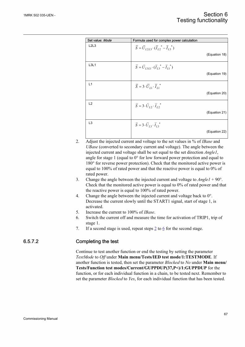
Set value: Mode Formula used for complex power calculationL2L3 * *
2 3 2 3( )L L L LS U I I= × -
EQUATION1701 V1 EN (Equation 18)
L3L1 * *3 1 3 1( )L L L LS U I I= × -
EQUATION1702 V1 EN (Equation 19)
L1 *1 13 L LS U I= × ×
EQUATION1703 V1 EN (Equation 20)
L2 *2 23 L LS U I= × ×
EQUATION1704 V1 EN (Equation 21)
L3 *3 33 L LS U I= × ×
EQUATION1705 V1 EN (Equation 22)
2. Adjust the injected current and voltage to the set values in % of IBase andUBase (converted to secondary current and voltage). The angle between theinjected current and voltage shall be set equal to the set direction Angle1,angle for stage 1 (equal to 0° for low forward power protection and equal to180° for reverse power protection). Check that the monitored active power isequal to 100% of rated power and that the reactive power is equal to 0% ofrated power.
3. Change the angle between the injected current and voltage to Angle1 + 90°.Check that the monitored active power is equal to 0% of rated power and thatthe reactive power is equal to 100% of rated power.
4. Change the angle between the injected current and voltage back to 0°.Decrease the current slowly until the START1 signal, start of stage 1, isactivated.
5. Increase the current to 100% of IBase.6. Switch the current off and measure the time for activation of TRIP1, trip of
stage 1.7. If a second stage is used, repeat steps 2 to 6 for the second stage.
6.5.7.2 Completing the test
Continue to test another function or end the testing by setting the parameterTestMode to Off under Main menu/Tests/IED test mode/1:TESTMODE. Ifanother function is tested, then set the parameter Blocked to No under Main menu/Tests/Function test modes/Current/GUPPDUP(37,P<)/1:GUPPDUP for thefunction, or for each individual function in a chain, to be tested next. Remember toset the parameter Blocked to Yes, for each individual function that has been tested.
1MRK 502 035-UEN - Section 6Testing functionality
67Commissioning Manual
6.5.8 Directional overpower protection GOPPDOPPrepare the IED for verification of settings as outlined in 5.1 "Preparing the IED toverify settings".
Values of the logical signals for GOPPDOP are available on the local HMI underMain menu/Tests/Function status/Current/GOPPDOP(32,P>)/X:GOPPDOP.The Signal Monitoring in PCM600 shows the same signals that are available on thelocal HMI.
6.5.8.1 Verifying the settings
The overpower protection shall be set to values according to the real set values tobe used. The test is made by means of injection of voltage and current where theamplitude of both current and voltage and the phase angle between the voltage andcurrent can be controlled. During the test the analog outputs of active and reactivepower shall be monitored.
1. Connect the test set for injection of voltage and current corresponding to themode to be used in the application. If a three phase test set is available thiscould be used for all the modes. If a single phase current/voltage test set isavailable the test set should be connected to a selected input for one phasecurrent and voltage.Use the formulas stated in Table 3 for the different calculation modes used.The set mode Mode can be found under Main menu/Settings/IED Settings/Current/GOPPDOP(32,P>)/1:GOPPDOP/General.
2. Adjust the injected current and voltage to the set rated values in % of IBaseand UBase (converted to secondary current and voltage). The angle betweenthe injected current and voltage shall be set equal to the set direction Angle1,angle for stage 1 (equal to 0° for low forward power protection and equal to180° for reverse power protection). Check that the monitored active power isequal to 100% of rated power and that the reactive power is equal to 0% ofrated power.
3. Change the angle between the injected current and voltage to Angle1 + 90°.Check that the monitored active power is equal to 0% of rated power and thatthe reactive power is equal to 100% of rated power.
4. Change the angle between the injected current and voltage back to Angle1value. Increase the current slowly from 0 until the START1 signal, start ofstage 1, is activated. Check the injected power and compare it to the set valuePower1, power setting for stage 1 in % of Sbase.
5. Increase the current to 100% of IBase and switch the current off.6. Switch the current on and measure the time for activation of TRIP1, trip of
stage 1.7. If a second stage is used, repeat steps 2 to 6 for the second stage.
Section 6 1MRK 502 035-UEN -Testing functionality
68Commissioning Manual
6.5.8.2 Completing the test
Continue to test another function or end the testing by setting the parameterTestMode to Off under Main menu/Tests/IED test mode/1:TESTMODE. Ifanother function is tested, then set the parameter Blocked to No under Main menu/Tests/Function test modes/Current/GOPPDOP(32,P>)/X:GOPPDOP for thefunction, or for each individual function in a chain, to be tested next. Remember toset the parameter Blocked to Yes, for each individual function that has been tested.
6.5.9 Accidental energizing protection for synchronous generatorAEGGAPCPrepare the IED for verification of settings as outlined in 5.1 "Preparing the IED toverify settings".
Values of the logical signals for AEGGAPC are available on the local HMI underMain menu/Tests/Function status/Current/AEGGAPC(50AE,U<&I>)/1:AEGGAPC. The Signal Monitoring in PCM600 shows the same signals that areavailable on the local HMI.
6.5.9.1 Verifying the settings
1. Connect the test set for three-phase current injection and for three phasevoltage injection to the appropriate IED terminals.
2. Inject zero voltage to the IED.3. Increase the injected symmetric three phase current slowly and note the
operated value (start value).4. Decrease the current slowly and note the reset value.5. Connect a trip output contact to a timer.6. Set the injected current to 200% of the operate level, switch on the current
and check the time delay.7. Check that all trip and start contacts operate according to the configuration
(signal matrises).8. Finally check that start and trip information is stored in the event menu.9. Inject rated symmetric three phase voltage to the IED.10. Set the injected current to 200% of the operate level, switch on the current.
The function shall not start and trip.11. Inject 95% of the set ArmU< value symmetric three-phase voltage to the IED.12. Set the injected current to 200% of the operate level, switch on the current.
The function shall start and trip.
6.5.10 Negative-sequence time overcurrent protection formachines NS2PTOC
1MRK 502 035-UEN - Section 6Testing functionality
69Commissioning Manual
Prepare the IED for verification of settings as outlined in 5.1 "Preparing the IED toverify settings".
Values of the logical signals for NS2PTOC are available on the local HMI underMain menu/Tests/Function status/Current/NS2PTOC(46I2,2I2>)/1:NS2PTOC. The Signal Monitoring in PCM600 shows the same signals that areavailable on the local HMI.
6.5.10.1 Verifying settings by secondary injection
1. Connect the test set for injection of three-phase currents to the appropriatecurrent terminals of the IED.
2. Go to Main menu/Settings/IED Settings/Current/NS2PTOC(46I2,2I2>)/1:NS2PTOC/General and make sure that the function is enabled, that isOperation is set to On.
3. Inject current into IEDs in such a way that negative sequence component iscreated and then verify that negative sequence component of the injectedcurrents is calculated correctly by the function. See example below for 1 Arated current transformer.
4. Inject pure negative sequence current, that is, phase currents with exactlysame magnitude, reversed sequence and exactly 120° phase displaced into theIED with an initial value below negative sequence current start level. Nooutput signals should be activated.Note: If it is difficult to obtain pure negative sequence current for thesecondary injection test, a current corresponding to the two phase short-circuit condition can be used. A two phase short-circuit gives a negativesequence current of a magnitude: magnitude = (1/√3) · fault current.
5. Increase the injected current and note the value at which the step 1 of thefunction operates. Start signal ST1 must be activated when amplitude of thenegative sequence current lies slightly above the start level I2-1>.Corresponding trip signals TR1 and TRIP is activated after the pre-set timedelay has expired.Note: Block or disable operation of step 2 when testing step 1 if the injectedcurrent activates the step 2.
6. Decrease the current slowly and note the reset value.7. Connect a trip output contact to a timer.8. Set the current to 200 % of the start level of the step 1, switch on the current
and check the definite time delay for trip signals TR1 and TRIP. Once themeasured negative sequence current exceeds the set atart level I2-1>, thesettable definite timer t1 starts to count and trip signals is released after theset time delay has elapsed. The same test must be carried out to check theaccuracy of definite time delay for ALARM signal.Note: The output ALARM is operated by START signal.
9. If inverse time is selected the trip signals TR1 and TRIP operates after a timecorresponding to the formula:
Section 6 1MRK 502 035-UEN -Testing functionality
70Commissioning Manual
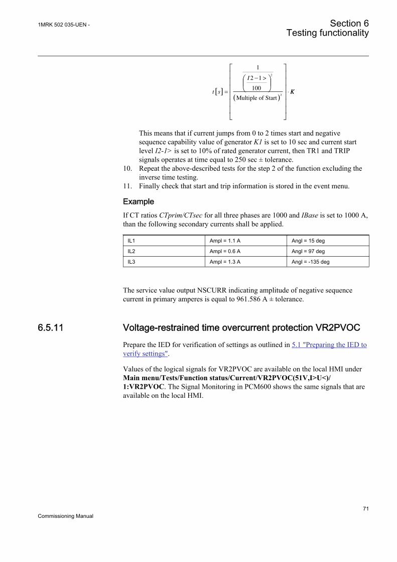
t s
I
[ ]
( )
=
− >
⋅
1
2 1
100
2
2
Multiple of Start
KK
This means that if current jumps from 0 to 2 times start and negativesequence capability value of generator K1 is set to 10 sec and current startlevel I2-1> is set to 10% of rated generator current, then TR1 and TRIPsignals operates at time equal to 250 sec ± tolerance.
10. Repeat the above-described tests for the step 2 of the function excluding theinverse time testing.
11. Finally check that start and trip information is stored in the event menu.
ExampleIf CT ratios CTprim/CTsec for all three phases are 1000 and IBase is set to 1000 A,than the following secondary currents shall be applied.
IL1 Ampl = 1.1 A Angl = 15 deg
IL2 Ampl = 0.6 A Angl = 97 deg
IL3 Ampl = 1.3 A Angl = -135 deg
The service value output NSCURR indicating amplitude of negative sequencecurrent in primary amperes is equal to 961.586 A ± tolerance.
6.5.11 Voltage-restrained time overcurrent protection VR2PVOCPrepare the IED for verification of settings as outlined in 5.1 "Preparing the IED toverify settings".
Values of the logical signals for VR2PVOC are available on the local HMI underMain menu/Tests/Function status/Current/VR2PVOC(51V,I>U<)/1:VR2PVOC. The Signal Monitoring in PCM600 shows the same signals that areavailable on the local HMI.
1MRK 502 035-UEN - Section 6Testing functionality
71Commissioning Manual
6.5.11.1 Verifying the settings
Built-in overcurrent feature (non-directional)
1. Go to Main menu/Test/Function test modes/Current protection and makesure that VR2PVOC to be tested is unblocked and other functions that mightdisturb the evaluation of the test are blocked.
2. Connect the test set for injection of three-phase currents to the appropriatecurrent terminals of the IED.
3. Inject three-phase current(s). Increase the current(s) until the functionoperates and check against the set operate value, for example when voltage isreduced to 50% of rated the overcurrent start shall be 50% of the current startvalue for rated voltage.
4. Decrease the current slowly and check the reset value.5. Connect a TRIP output contact to the timer.6. Set the current to 200% of the operate value, switch on the current and check
the time delay.For inverse time curves, check the operate time at a current equal to 110% ofthe operate current at tMin.
7. Check that TRIP and START contacts operate according to the configurationlogic.
8. Finally check that START and TRIP information is stored in the event menu.
Information on how to use the event menu is found in theoperators manual.
Overcurrent feature with voltage restraint
1. Connect the test set for injection of three-phase currents and three-phasevoltages to the appropriate current and voltage terminals of the IED.
2. Inject the rated voltage during the next steps in order for function to operateproperly.
3. Inject three-phase current(s) and voltage(s).Overall check in principle as non-directional overcurrent feature.
4. Operate value measurementThe relevant voltage restraining value must also be injected from the test setand the influence on the operate value has to be calculated when testing theoperate value is completed.
5. Operate time measurementDefinite times may be tested as above. For inverse time characteristics theSTART value, to which the overcurrent ratio has to be calculated, is theactual start value as got with actual restraining from the voltage restrainingquantity.
Section 6 1MRK 502 035-UEN -Testing functionality
72Commissioning Manual
6.5.11.2 Completing the test
Continue to test another function or end the testing by setting the parameterTestMode to Off under Main menu/Tests/IED test mode/1:TESTMODE. Ifanother function is tested, then set the parameter Blocked to No under Main menu/Tests/Function test modes/Current/VR2PVOC(51V,I>U<)/1:VR2PVOC forthe function, or for each individual function in a chain, to be tested next.Remember to set the parameter Blocked to Yes, for each individual function thathas been tested.
6.6 Testing voltage protection functions
6.6.1 Two step undervoltage protection UV2PTUVPrepare the IED for verification of settings as outlined in 5.1 "Preparing the IED toverify settings".
Values of the logical signals for UV2PTUV are available on the local HMI underMain menu/Tests/Function status/Voltage/UV2PTUV(27,2U<)/1:UV2PTUV.The Signal Monitoring in PCM600 shows the same signals that are available on thelocal HMI.
6.6.1.1 Verifying the setting
Verification of START value and time delay to operate for Step1
1. Check that the IED settings are appropriate, especially the START value, thedefinite time delay and the 1 out of 3 operation mode.
2. Supply the IED with three-phase voltages at their rated values.3. Slowly decrease the voltage in one of the phases, until the START signal
appears.4. Note the operate value and compare it with the set value.5. Increase the measured voltage to rated load conditions.6. Check that the START signal resets.7. Instantaneously decrease the voltage in one phase to a value about 20% lower
than the measured operate value.8. Measure the time delay for the TRIP signal, and compare it with the set value.
Extended testing
1. The test above can now be repeated for step 2.2. The tests above can be repeated for 2 out of 3 and for 3 out of 3 operation mode.3. The tests above can be repeated to check security, that is, the START and
operate signals, that are not supposed to appear, - do not.4. The tests above can be repeated to check the time to reset.5. The tests above can be repeated to test the inverse time characteristic.
1MRK 502 035-UEN - Section 6Testing functionality
73Commissioning Manual
6.6.1.2 Completing the test
Continue to test another function or end the testing by setting the parameterTestMode to Off under Main menu/Tests/IED test mode/1:TESTMODE. Ifanother function is tested, then set the parameter Blocked to No under Main menu/Tests/Function test modes/Voltage/UV2PTUV(27,2U<)/1:UV2PTUV for thefunction, or for each individual function in a chain, to be tested next. Remember toset the parameter Blocked to Yes, for each individual function that has been tested.
6.6.2 Two step overvoltage protection OV2PTOVPrepare the IED for verification of settings as outlined in 5.1 "Preparing the IED toverify settings".
Values of the logical signals for OV2PTOV are available on the local HMI underMain menu/Tests/Function status/Voltage/OV2PTOV(59,2U>)/1:OV2PTOV.The Signal Monitoring in PCM600 shows the same signals that are available on thelocal HMI.
6.6.2.1 Verifying the settings
1. Apply single-phase voltage below the set value U1>.2. Slowly increase the voltage until the ST1 signal appears.3. Note the operate value and compare it with the set value.4. Switch the applied voltage off.5. Set and apply about 20% higher voltage than the measured operate value for
one phase.6. Measure the time delay for the TR1 signal and compare it with the set value.7. Repeat the test for step 2.
6.6.2.2 Completing the test
Continue to test another function or end the testing by setting the parameterTestMode to Off under Main menu/Tests/IED test mode/1:TESTMODE. Ifanother function is tested, then set the parameter Blocked to No under Main menu/Tests/Function test modes/Voltage/OV2PTOV(59,2U>)/1:OV2PTOV for thefunction, or for each individual function in a chain, to be tested next. Remember toset the parameter Blocked to Yes, for each individual function that has been tested.
6.6.3 Two step residual overvoltage protection ROV2PTOVPrepare the IED for verification of settings as outlined in 5.1 "Preparing the IED toverify settings".
Values of the logical signals for ROV2PTOV are available on the local HMI underMain menu/Tests/Function status/Voltage/ROV2PTOV(59N,2UN>)/
Section 6 1MRK 502 035-UEN -Testing functionality
74Commissioning Manual
1:ROV2PTOV. The Signal Monitoring in PCM600 shows the same signals thatare available on the local HMI.
6.6.3.1 Verifying the settings
1. Apply the single-phase voltage either to a single phase voltage input or to aresidual voltage input with the start value below the set value U1>.
2. Slowly increase the value until ST1 appears.3. Note the operate value and compare it with the set value.4. Switch the applied voltage off.5. Set and apply about 20% higher voltage than the measured operate value for
one phase.6. Measure the time delay for the TR1 signal and compare it with the set value.7. Repeat the test for step 2.
6.6.3.2 Completing the test
Continue to test another function or end the testing by setting the parameterTestMode to Off under Main menu/Tests/IED test mode/1:TESTMODE. Ifanother function is tested, then set the parameter Blocked to No under Main menu/Tests/Function test modes/Voltage/ROV2PTOV(59N,2UN>)/1:ROV2PTOVfor the function, or for each individual function in a chain, to be tested next.Remember to set the parameter Blocked to Yes, for each individual function thathas been tested.
6.6.4 Overexcitation protection OEXPVPHPrepare the IED for verification of settings as outlined in 5.1 "Preparing the IED toverify settings".
Values of the logical signals for OEXPVPH are available on the local HMI underMain menu/Tests/Function status/Voltage/OEXPVPH(24,U/f>)/1:OEXPVPH.The Signal Monitoring in PCM600 shows the same signals that are available on thelocal HMI.
6.6.4.1 Verifying the settings
1. Enable function.2. Connect a symmetrical three-phase voltage input from the test set to the
appropriate connection terminals of the overexcitation protection OEXPVPH.OEXPVPH is conveniently tested using rated frequency for the injectionvoltage and increasing the injection voltage to get the desired overexcitationlevel.
3. Connect the alarm contact to the timer and set the time delay tAlarmtemporarily to zero.
1MRK 502 035-UEN - Section 6Testing functionality
75Commissioning Manual
4. Increase the voltage and note the operate value V/Hz>.5. Reduce the voltage slowly and note the reset value.6. Set the alarm time delay to the correct value according to the setting plan and
check the time delay, injecting a voltage corresponding to 1.2 · V/Hz>.7. Connect a trip output contact to the timer and temporarily set the time delay
tMin to 0.5s.8. Increase the voltage and note the V/Hz>> operate value9. Reduce the voltage slowly and note the reset value.10. Set the time delay to the correct value according to the setting plan and check
the time delay tMin, injecting a voltage corresponding to 1.2 · V/Hz>>.11. Check that trip and alarm contacts operate according to the configuration logic.12. Finally check that START and TRIP information is stored in the event menu.
6.6.4.2 Completing the test
Continue to test another function or end the testing by setting the parameterTestMode to Off under Main menu/Tests/IED test mode/1:TESTMODE. Ifanother function is tested, then set the parameter Blocked to No under Main menu/Tests/Function test modes/Voltage/OEXPVPH(24,U/f>)/1:OEXPVPH for thefunction, or for each individual function in a chain, to be tested next. Remember toset the parameter Blocked to Yes, for each individual function that has been tested.
6.6.5 100% Stator earth fault protection, 3rd harmonic basedSTEFPHIZPrepare the IED for verification of settings as outlined in 5.1 "Preparing the IED toverify settings".
Values of the logical signals for STEFPHIZ are available on the local HMI underMain menu/Tests/Function status/Voltage/STEFPHIZ(59THD)/1:STEFPHIZ.The Signal Monitoring in PCM600 shows the same signals that are available on thelocal HMI.
6.6.5.1 Testing
The protection function uses measurement of the third-harmonic voltages in theneutral point of the generator and on the generator terminal (broken delta voltagetransformer connection to the IED).
The test set shall be capable to generate third-harmonic voltages. One voltage(UN3) is connected to the residual voltage input related to the terminal side of thegenerator. The second voltage (UN3) is connected to the voltage input related to theneutral of the generator. The angle between the injected third-harmonic voltagesshall be adjustable.
Section 6 1MRK 502 035-UEN -Testing functionality
76Commissioning Manual
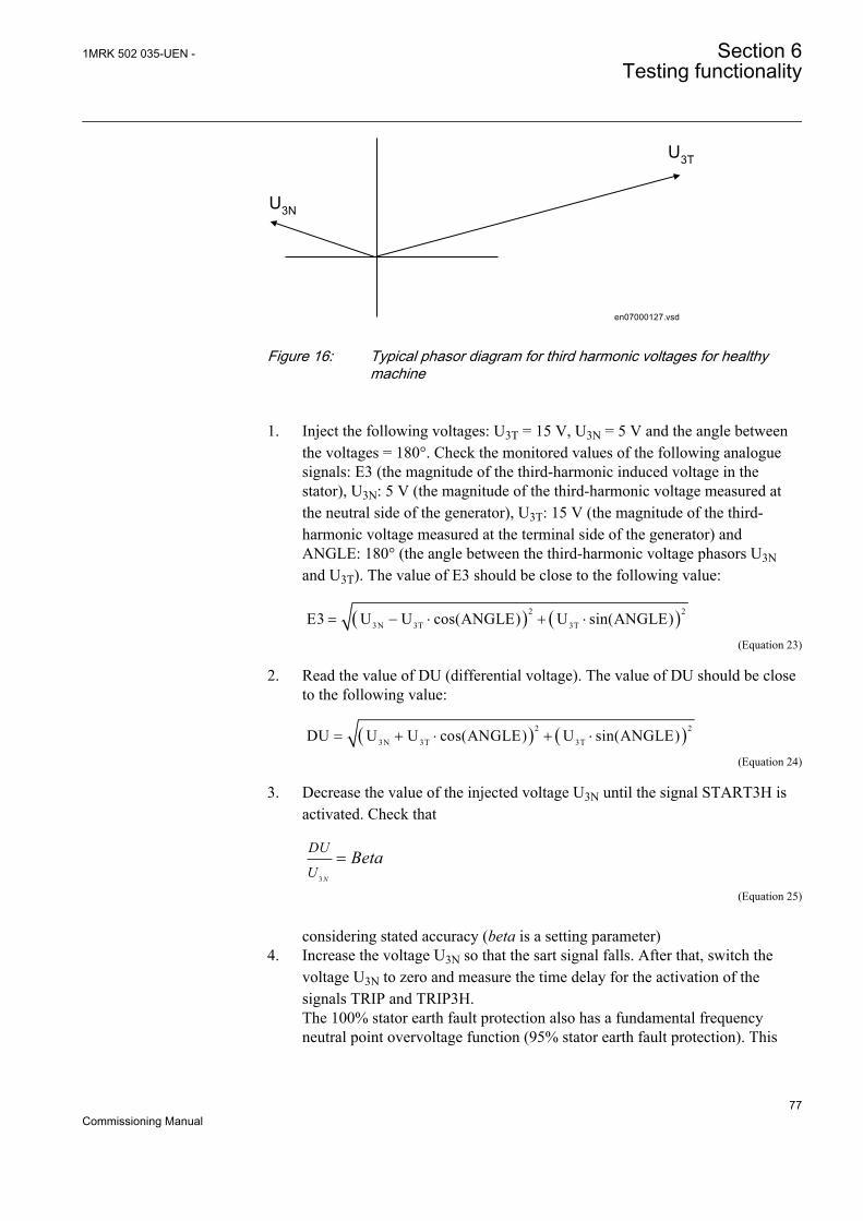
en07000127.vsd
U3N
U3T
IEC07000127 V1 EN
Figure 16: Typical phasor diagram for third harmonic voltages for healthymachine
1. Inject the following voltages: U3T = 15 V, U3N = 5 V and the angle betweenthe voltages = 180°. Check the monitored values of the following analoguesignals: E3 (the magnitude of the third-harmonic induced voltage in thestator), U3N: 5 V (the magnitude of the third-harmonic voltage measured atthe neutral side of the generator), U3T: 15 V (the magnitude of the third-harmonic voltage measured at the terminal side of the generator) andANGLE: 180° (the angle between the third-harmonic voltage phasors U3Nand U3T). The value of E3 should be close to the following value:
( ) ( )2 2
3N 3T 3TE3 U U cos(ANGLE) U sin(ANGLE)= - × + ×
EQUATION2070 V1 EN (Equation 23)
2. Read the value of DU (differential voltage). The value of DU should be closeto the following value:
( ) ( )2 2
3N 3T 3TDU U U cos(ANGLE) U sin(ANGLE)= + × + ×
EQUATION2071 V1 EN (Equation 24)
3. Decrease the value of the injected voltage U3N until the signal START3H isactivated. Check that
3 N
DU
UBeta=
EQUATION2072 V2 EN (Equation 25)
considering stated accuracy (beta is a setting parameter)4. Increase the voltage U3N so that the sart signal falls. After that, switch the
voltage U3N to zero and measure the time delay for the activation of thesignals TRIP and TRIP3H.The 100% stator earth fault protection also has a fundamental frequencyneutral point overvoltage function (95% stator earth fault protection). This
1MRK 502 035-UEN - Section 6Testing functionality
77Commissioning Manual
part of the protection can be tested separately by means of fundamentalfrequency voltage injection from a test equipment.
6.6.5.2 Verifying settings
1. With the generator rotating at rated speed but not connected: check the valueof the following analogue signals: E3 (the magnitude of the 3rd harmonicinduced voltage in the stator), U3N (the magnitude of the third-harmonicvoltage measured at the neutral side of the generator), U3T (the magnitude ofthe third-harmonic voltage measured at the terminal side of the generator) andANGLE (the angle between the third-harmonic voltage phasors U3N andU3T). The value of E3 should be close to the following value:
( ) ( )2 2
3N 3T 3TE3 U U cos(ANGLE) U sin(ANGLE)= - × + ×
EQUATION2076 V1 EN (Equation 26)
Make sure that ANGLE has a value bigger than 125°2. Read the value of DU (differential voltage). The value of DU should be close
to the following value:
( ) ( )2 2
3N 3T 3TDU U U cos(ANGLE) U sin(ANGLE)= + × + ×
EQUATION2078 V1 EN (Equation 27)
3. Read the value of BU (bias voltage: Beta ·U3N). The ratio DU/BU should bewell below 1 for a non-faulted generator.
4. After synchronization of the generator the ratio DU/BU is checked fordifferent load levels of the generator. These different monitoring of loadlevels should be the base for the setting of beta.If the function is used with the option of neutral point measurement only thetest is performed by check of this voltage. The operate value should be abovethe measured residual third-harmonic voltage in the neutral point at normaloperation (non-faulted generator).
6.6.5.3 Completing the test
Continue to test another function or end the testing by setting the parameterTestMode to Off under Main menu/Tests/IED test mode/1:TESTMODE. Ifanother function is tested, then set the parameter Blocked to No under Main menu/Tests/Function test modes/Voltage/STEFPHIZ(59THD)/1:STEFPHIZ for thefunction, or for each individual function in a chain, to be tested next. Remember toset the parameter Blocked to Yes, for each individual function that has been tested.
Section 6 1MRK 502 035-UEN -Testing functionality
78Commissioning Manual
6.6.6 Rotor earth fault protection 64RGenerator rotor winding and its associated dc supply electric circuit is typicallyfully insulated from the earth (that is, ground). Therefore single connection of thiscircuit to earth will not cause flow of any substantial current. However if secondearth fault appears in this circuit circumstances can be quit serious. Depending onthe location of these two faults such operating condition may cause:
• Partial or total generator loss of field• Large dc current flow through rotor magnetic circuit• Rotor vibration• Rotor displacement sufficient to cause stator mechanical damage
Therefore practically all bigger generators have some dedicated protection which iscapable to detect the first earth fault in the rotor circuit and then, depending on thefault resistance, either just to give an alarm to the operating personnel or actually togive stop command to the machine.
Rotor earth fault protection can be integrated in REG650 among allother protection functions typically required for generatorprotection. Instruction 1MRG001910 gives an example of a testingprocedure by using COMBIFLEX injection unit RXTTE4.
6.7 Testing frequency protection functions
6.7.1 Underfrequency protection SAPTUFPrepare the IED for verification of settings as outlined in 5.1 "Preparing the IED toverify settings".
Values of the logical signals for SAPTUF are available on the local HMI underMain menu/Tests/Function status/Frequency/SAPTUF(81,f<)/X:SAPTUF. TheSignal Monitoring in PCM600 shows the same signals that are available on thelocal HMI.
6.7.1.1 Verifying the settings
Verification of START value and time delay to operate
1. Check that the IED settings are appropriate, especially the START value andthe definite time delay.
2. Supply the IED with three-phase voltages at their rated values.3. Slowly decrease the frequency of the applied voltage, until the START signal
appears.
1MRK 502 035-UEN - Section 6Testing functionality
79Commissioning Manual
4. Note the operate value and compare it with the set value.5. Increase the frequency until rated operating levels are reached.6. Check that the START signal resets.7. Instantaneously decrease the frequency of the applied voltage to a value about
20% lower than the operate value.8. Measure the time delay of the TRIP signal, and compare it with the set value.
Extended testing
1. The test above can be repeated to check the time to reset.2. The tests above can be repeated to test the frequency dependent inverse time
characteristic.
Verification of the low voltage magnitude blocking
1. Check that the IED settings are appropriate, especially the StartFrequencyand the tDelay and the MinValFreqMeas in the SMAI preprocessing function.
2. Supply the IED with three-phase voltages at rated values.3. Slowly decrease the magnitude of the applied voltage, until the BLKDMAGN
signal appears.4. Note the voltage magnitude value and compare it with the SMAI set value
MinValFreqMeas.5. Slowly decrease the frequency of the applied voltage, to a value below
StartFrequency.6. Check that the START signal does not appear.7. Wait for a time corresponding to tDelay, and check that the TRIP signal does
not appear.
6.7.1.2 Completing the test
Continue to test another function or end the testing by setting the parameterTestMode to Off under Main menu/Tests/IED test mode/1:TESTMODE. Ifanother function is tested, then set the parameter Blocked to No under Main menu/Tests/Function test modes/Frequency/SAPTUF(81,f<)/X:SAPTUF for thefunction, or for each individual function in a chain, to be tested next. Remember toset the parameter Blocked to Yes, for each individual function that has been tested.
6.7.2 Overfrequency protection SAPTOFPrepare the IED for verification of settings as outlined in 5.1 "Preparing the IED toverify settings".
Values of the logical signals for SAPTOF are available on the local HMI underMain menu/Tests/Function status/Frequency/SAPTOF(81,f>)/X:SAPTOF. TheSignal Monitoring in PCM600 shows the same signals that are available on thelocal HMI.
Section 6 1MRK 502 035-UEN -Testing functionality
80Commissioning Manual
6.7.2.1 Verifying the settings
Verification of START value and time delay to operate
1. Check that the settings in the IED are appropriate, especially the STARTvalue and the definite time delay.
2. Supply the IED with three-phase voltages at their rated values.3. Slowly increase the frequency of the applied voltage, until the START signal
appears.4. Note the operate value and compare it with the set value.5. Decrease the frequency to rated operating conditions.6. Check that the START signal resets.7. Instantaneously increase the frequency of the applied voltage to a value about
20% higher than the operate value.8. Measure the time delay for the TRIP signal, and compare it with the set value.
Extended testing
1. The test above can be repeated to check the time to reset.
Verification of the low voltage magnitude blocking
1. Check that you have appropriate settings in the IED, especially theStartFrequency, TtDelay and the MinValFreqMeas in the SMAIpreprocessing function
2. Supply the IED with three-phase voltages at their rated values.3. Slowly decrease the magnitude of the applied voltage, until the BLKDMAGN
signal appears.4. Note the voltage magnitude value and compare it with the set value,
MinValFreqMeas.5. Slowly increase the frequency of the applied voltage, to a value above
StartFrequency.6. Check that the START signal does not appear.7. Wait for a time corresponding to tDelay, and make sure that the TRIP signal
does not appear.
6.7.2.2 Completing the test
Continue to test another function or end the testing by setting the parameterTestMode to Off under Main menu/Tests/IED test mode/1:TESTMODE. Ifanother function is tested, then set the parameter Blocked to No under Main menu/Tests/Function test modes/Frequency/SAPTOF(81,f>)/X:SAPTOF for thefunction, or for each individual function in a chain, to be tested next. Remember toset the parameter Blocked to Yes, for each individual function that has been tested.
1MRK 502 035-UEN - Section 6Testing functionality
81Commissioning Manual
6.7.3 Rate-of-change frequency protection SAPFRCPrepare the IED for verification of settings as outlined in 5.1 "Preparing the IED toverify settings".
Values of the logical signals for SAPFRC are available on the local HMI underMain menu/Tests/Function status/Frequency/SAPFRC(81,df/dt)/X:SAPFRC.The Signal Monitoring in PCM600 shows the same signals that are available on thelocal HMI.
6.7.3.1 Verifying the settings
Verification of START value and time delay to operate
1. Check that the appropriate settings are available in the IED, especially theSTART value and the definite time delay. Set StartFreqGrad, to a rathersmall negative value.
2. Supply the IED with three-phase voltages at their rated values.3. Slowly decrease the frequency of the applied voltage, with an increasing rate-
of-change that finally exceeds the setting of StartFreqGrad, and check thatthe START signal appears.
4. Note the operate value and compare it with the set value.5. Increase the frequency to rated operating conditions, and zero rate-of-change.6. Check that the START signal resets.7. Instantaneously decrease the frequency of the applied voltage to a value about
20% lower than the nominal value.8. Measure the time delay for the TRIP signal, and compare it with the set value.
Extended testing
1. The test above can be repeated to check a positive setting of StartFreqGrad.2. The tests above can be repeated to test the RESTORE signal, when the
frequency recovers from a low value.
6.7.3.2 Completing the test
Continue to test another function or end the testing by setting the parameterTestMode to Off under Main menu/Tests/IED test mode/1:TESTMODE. Ifanother function is tested, then set the parameter Blocked to No under Main menu/Tests/Function test modes/Frequency/SAPFRC(81,df/dt)/X:SAPFRC for thefunction, or for each individual function in a chain, to be tested next. Remember toset the parameter Blocked to Yes, for each individual function that has been tested.
Section 6 1MRK 502 035-UEN -Testing functionality
82Commissioning Manual
6.8 Testing secondary system supervision functions
6.8.1 Fuse failure supervision SDDRFUFPrepare the IED for verification of settings as outlined in 5.1 "Preparing the IED toverify settings".
Values of the logical signals for SDDRFUF are available on the local HMI underMain menu/Tests/Function status/Secondary system supervision/SDDRFUF/1:SDDRFUF. The Signal Monitoring in PCM600 shows the same signals that areavailable on the local HMI.
The verification is divided in two main parts. The first part is common to all fusefailure supervision options, and checks that binary inputs and outputs operate asexpected according to actual configuration. In the second part the relevant setoperate values are measured.
6.8.1.1 Checking that the binary inputs and outputs operate as expected
1. Simulate normal operating conditions with the three-phase currents in phasewith their corresponding phase voltages and with all of them equal to theirrated values.
2. Connect the nominal dc voltage to the DISCPOS binary input.• The signal BLKU should appear with almost no time delay.• No signals BLKZ and 3PH should appear on the IED.• Only the distance protection function can operate.• Undervoltage-dependent functions must not operate.
3. Disconnect the dc voltage from the DISCPOS binary input terminal.4. Connect the nominal dc voltage to the MCBOP binary input.
• The BLKU and BLKZ signals should appear without any time delay.• All undervoltage-dependent functions must be blocked.
5. Disconnect the dc voltage from the MCBOP binary input terminal.6. Disconnect one of the phase voltages and observe the logical output signals
on the binary outputs of the IED. BLKU and BLKZ signals shouldsimultaneously appear.BLKU and BLKZ signals should simultaneously appear.
7. After more than 5 seconds disconnect the remaining two-phase voltages andall three currents.• There should be no change in the high status of the output signals
BLKU and BLKZ.• The signal 3PH will appear.
8. Establish normal voltage and current operating conditions simultaneously andobserve the corresponding output signals.They should change to logical 0 as follows:
1MRK 502 035-UEN - Section 6Testing functionality
83Commissioning Manual
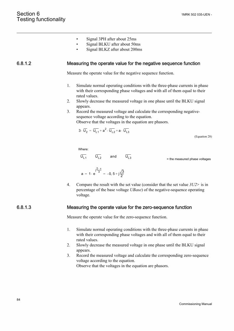
• Signal 3PH after about 25ms• Signal BLKU after about 50ms• Signal BLKZ after about 200ms
6.8.1.2 Measuring the operate value for the negative sequence function
Measure the operate value for the negative sequence function.
1. Simulate normal operating conditions with the three-phase currents in phasewith their corresponding phase voltages and with all of them equal to theirrated values.
2. Slowly decrease the measured voltage in one phase until the BLKU signalappears.
3. Record the measured voltage and calculate the corresponding negative-sequence voltage according to the equation.Observe that the voltages in the equation are phasors.
3 U2× UL1 a2 UL2 a+× UL3×+=
EQUATION707 V1 EN (Equation 28)
Where:
UL1 UL2 and UL3EQUATION708 V1 EN
= the measured phase voltages
a 1 ej 2 p×
3-----------
× 0 5 j 32
-------+,–= =EQUATION709 V1 EN
4. Compare the result with the set value (consider that the set value 3U2> is inpercentage of the base voltage UBase) of the negative-sequence operatingvoltage.
6.8.1.3 Measuring the operate value for the zero-sequence function
Measure the operate value for the zero-sequence function.
1. Simulate normal operating conditions with the three-phase currents in phasewith their corresponding phase voltages and with all of them equal to theirrated values.
2. Slowly decrease the measured voltage in one phase until the BLKU signalappears.
3. Record the measured voltage and calculate the corresponding zero-sequencevoltage according to the equation.Observe that the voltages in the equation are phasors.
Section 6 1MRK 502 035-UEN -Testing functionality
84Commissioning Manual
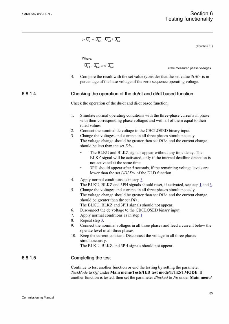
3 U0× UL1 UL2 UL3+ +=
IEC00000276 V1 EN (Equation 31)
Where:
UL1 , UL2 and UL3
IEC00000275 V1 EN
= the measured phase voltages.
4. Compare the result with the set value (consider that the set value 3U0> is inpercentage of the base voltage of the zero-sequence operating voltage.
6.8.1.4 Checking the operation of the du/dt and di/dt based function
Check the operation of the du/dt and di/dt based function.
1. Simulate normal operating conditions with the three-phase currents in phasewith their corresponding phase voltages and with all of them equal to theirrated values.
2. Connect the nominal dc voltage to the CBCLOSED binary input.3. Change the voltages and currents in all three phases simultaneously.
The voltage change should be greater then set DU> and the current changeshould be less than the set DI<.• The BLKU and BLKZ signals appear without any time delay. The
BLKZ signal will be activated, only if the internal deadline detection isnot activated at the same time.
• 3PH should appear after 5 seconds, if the remaining voltage levels arelower than the set UDLD< of the DLD function.
4. Apply normal conditions as in step 3.The BLKU, BLKZ and 3PH signals should reset, if activated, see step 1 and 3.
5. Change the voltages and currents in all three phases simultaneously.The voltage change should be greater than set DU> and the current changeshould be greater than the set DI<.The BLKU, BLKZ and 3PH signals should not appear.
6. Disconnect the dc voltage to the CBCLOSED binary input.7. Apply normal conditions as in step 1.8. Repeat step 3.9. Connect the nominal voltages in all three phases and feed a current below the
operate level in all three phases.10. Keep the current constant. Disconnect the voltage in all three phases
simultaneously.The BLKU, BLKZ and 3PH signals should not appear.
6.8.1.5 Completing the test
Continue to test another function or end the testing by setting the parameterTestMode to Off under Main menu/Tests/IED test mode/1:TESTMODE. Ifanother function is tested, then set the parameter Blocked to No under Main menu/
1MRK 502 035-UEN - Section 6Testing functionality
85Commissioning Manual
Tests/Function test modes/Secondary system supervision/SDDRFUF/1:SDDRFUF for the function, or for each individual function in a chain, to betested next. Remember to set the parameter Blocked to Yes, for each individualfunction that has been tested.
6.9 Testing control functions
The save of persistent parts of function block states/values topersistent memory uses an exponential back-off algorithm, whichrapidly increases the time between save operations when there arefrequent changes in such states/values. This means, that when e.g. apulse counter is exercised periodically, the time between saves ofits counter value to persistent memory will occur more and moreseldom until there is one hour between save operations. If the IEDis restarted by turning auxiliary power off and back on, then up toone hour of counter value increments will be lost. This back-offalgorithm is necessary to avoid wearing out the FLASH memorythat is used to save the states/values. When changing parametervalues using LHMI or PST, there is a save of this type of memorybefore rebooting, so in this case normally no information is lost.When there are long periods of inactivity, the time between saveoperations decreases slowly again, until it reaches the minimumtime between saves, which is approximately once per second. Aftercommissioning is complete, the possible loss of information shouldnot be an issue, since in normal operation an IED is switched offextremely seldom. But during certain tests, if the IED is rebooted,then data of this kind will sometimes revert back to old values.
6.9.1 Synchrocheck, energizing check, and synchronizingSESRSYN
This section contains instructions on how to test the synchrocheck and energizingcheck for single CB.
Prepare the IED for verification of settings as outlined in 5.1 "Preparing the IED toverify settings".
Values of the logical signals for SESRSYN are available on the local HMI underMain menu/Tests/Function status/Control/SESRSYN(25,SYNC)/X:SESRSYN.The Signal Monitoring in PCM600 shows the same signals that are available on thelocal HMI.
Section 6 1MRK 502 035-UEN -Testing functionality
86Commissioning Manual
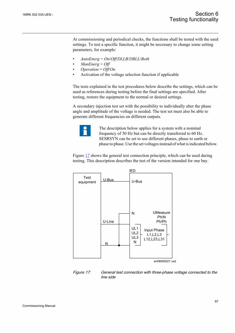
At commissioning and periodical checks, the functions shall be tested with the usedsettings. To test a specific function, it might be necessary to change some settingparameters, for example:
• AutoEnerg = On/Off/DLLB/DBLL/Both• ManEnerg = Off• Operation = Off/On• Activation of the voltage selection function if applicable
The tests explained in the test procedures below describe the settings, which can beused as references during testing before the final settings are specified. Aftertesting, restore the equipment to the normal or desired settings.
A secondary injection test set with the possibility to individually alter the phaseangle and amplitude of the voltage is needed. The test set must also be able togenerate different frequencies on different outputs.
The description below applies for a system with a nominalfrequency of 50 Hz but can be directly transferred to 60 Hz.SESRSYN can be set to use different phases, phase to earth orphase to phase. Use the set voltages instead of what is indicated below.
Figure 17 shows the general test connection principle, which can be used duringtesting. This description describes the test of the version intended for one bay.
Testequipment
UMeasurePh/NPh/Ph
en08000027.vsd
U-Bus
U-Line
N
IED
U-Bus
N
UL1UL2UL3
N
Input PhaseL1,L2,L3
L12,L23,L31
IEC08000027 V1 EN
Figure 17: General test connection with three-phase voltage connected to theline side
1MRK 502 035-UEN - Section 6Testing functionality
87Commissioning Manual
6.9.1.1 Testing the synchronizing function
This section is applicable only if the synchronizing function is included.
The voltage inputs used are:
ULine UL1, UL2 or UL3voltage inputs on the IED
U-Bus Bus voltage input on the IED
Testing the frequency differenceThe frequency difference is in the example set at 0.20 Hz on the local HMI, and thetest should verify that operation is achieved when the FreqDiffMax frequencydifference is lower than 0.20 Hz. The test procedure below will depend on thesettings used.
1. Apply voltages1.1. U-Line = 100% UBase and f-line = 50.0 Hz1.2. U-Bus = 100% UBase and f-bus = 50.2 Hz
2. Check that a closing pulse is submitted and at closing angle less than 2degrees from phase equality. Modern test sets will evaluate this automatically.
3. Repeat with3.1. U-Bus = 100% UBase and f-bus = 50.25 Hz3.2. Verify that the function does not operate when frequency difference is
above limit.4. Repeat with different frequency differences for example, 100 mHz with f-bus
nominal and line leading and for example 20 mHz (or just aboveFreqDiffMin) to verify that independent of frequency difference the closingpulse occurs within 2 degrees.
5. Verify that the closing command is not issued when the frequency differenceis less than the set value FreqDiffMin.
6.9.1.2 Testing the synchrocheck check
During the test of SESRSYN for a single bay arrangement, these voltage inputs areused:
U-Line UL1, UL2 or UL3 voltage input on the IED
U-Bus Bus voltage input on the IED
Testing the voltage differenceSet the voltage difference at 15% UBase on the local HMI, and the test shouldcheck that operation is achieved when the voltage difference UDiffSC is lower than15% UBase.
Section 6 1MRK 502 035-UEN -Testing functionality
88Commissioning Manual
The settings used in the test shall be final settings. The test shall be adapted to sitesetting values instead of values in the example below.
Test with no voltage difference between the inputs.
Test with a voltage difference higher than the set UDiffSC
1. Apply voltages U-Line (for example) = 80% UBase and U-Bus = 80% UBase.2. Check that the AUTOSYOK and MANSYOK outputs are activated.3. The test can be repeated with different voltage values to verify that the
function operates within the set UDiffSC. Check with both U-Line and U-Busrespectively lower than the other.
4. Increase the U-Bus to 110% UBase, and the U-Line = 90% UBase and alsothe opposite condition.
5. Check that the two outputs for manual and auto synchronism are not activated.
Testing the phase angle differenceThe phase angle differences PhaseDiffM and PhaseDiffA respectively are set totheir final settings and the test should verify that operation is achieved when thephase angle difference is lower than this value both leading and lagging.
Test with no voltage difference
1. Apply voltages U-Line (for example) = 100% UBase and U-Bus = 100%UBase, with a phase difference equal to 0 degrees and a frequency differencelower than FreqDiffA and FreqDiffM
2. Check that the AUTOSYOK and MANSYOK outputs are activated.The test can be repeated with other phase difference values to verify that thefunction operates for values lower than the set ones, PhaseDiffM andPhaseDiffA. By changing the phase angle on the voltage connected to U-Bus,between ± dφ degrees, the user can check that the two outputs are activatedfor a phase difference lower than the set value. It should not operate for othervalues. See figure 18.
1MRK 502 035-UEN - Section 6Testing functionality
89Commissioning Manual
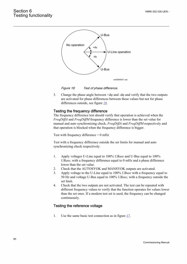
+dj
-dj
U-Bus
U-Line operation
U-Bus
No operation
en05000551.vsdIEC05000551 V1 EN
Figure 18: Test of phase difference.
3. Change the phase angle between +dφ and -dφ and verify that the two outputsare activated for phase differences between these values but not for phasedifferences outside, see figure 18.
Testing the frequency differenceThe frequency difference test should verify that operation is achieved when theFreqDiffA and FreqDiffM frequency difference is lower than the set value formanual and auto synchronizing check, FreqDiffA and FreqDiffM respectively andthat operation is blocked when the frequency difference is bigger.
Test with frequency difference = 0 mHz
Test with a frequency difference outside the set limits for manual and autosynchronizing check respectively.
1. Apply voltages U-Line equal to 100% UBase and U-Bus equal to 100%UBase, with a frequency difference equal to 0 mHz and a phase differencelower than the set value.
2. Check that the AUTOSYOK and MANSYOK outputs are activated.3. Apply voltage to the U-Line equal to 100% UBase with a frequency equal to
50 Hz and voltage U-Bus equal to 100% UBase, with a frequency outside theset limit.
4. Check that the two outputs are not activated. The test can be repeated withdifferent frequency values to verify that the function operates for values lowerthan the set ones. If a modern test set is used, the frequency can be changedcontinuously.
Testing the reference voltage
1. Use the same basic test connection as in figure 17.
Section 6 1MRK 502 035-UEN -Testing functionality
90Commissioning Manual
The voltage difference between the voltage connected to U-Bus and U-Lineshould be 0%, so that the AUTOSYOK and MANSYOK outputs areactivated first.
2. Change the U-Line voltage connection to U-Line2 without changing thesetting on the local HMI. Check that the two outputs are not activated.
6.9.1.3 Testing the energizing check
During the test of the energizing check function for a single bay arrangement, thesevoltage inputs are used:
U-Line UL1, UL2 or UL3 voltage input on the IED
U-Bus Bus voltage input on the IED
GeneralWhen testing the energizing check function for the applicable bus, arrangementshall be done for the energizing check functions. The voltage is selected byactivation of different inputs in the voltage selection logic.
The test shall be performed according to the settings for the station. Test thealternatives below that are applicable.
Testing the dead line live bus (DLLB)The test should verify that the energizing check function operates for a low voltageon the U-Line and for a high voltage on the U-Bus. This corresponds to theenergizing of a dead line to a live bus.
1. Apply a single-phase voltage 100% UBase to the U-Bus, and a single-phasevoltage 30% UBase to the U-Line.
2. Check that the AUTOENOK and MANENOK outputs are activated.3. Increase the U-Line to 60% UBase and U-Bus to be equal to 100% UBase.
The outputs should not be activated.4. The test can be repeated with different values on the U-Bus and the U-Line.
Testing the dead bus live line (DBLL)The test should verify that the energizing check function operates for a low voltageon the U-Bus and for a high voltage on the U-Line. This corresponds to anenergizing of a dead bus to a live line.
1. Verify the local HMI settings AutoEnerg or ManEnerg to be DBLL.2. Apply a single-phase voltage of 30% UBase to the U-Bus and a single-phase
voltage of 100% UBase to the U-Line.3. Check that the AUTOENOK and MANENOK outputs are activated.4. Decrease the U-Line to 60% UBase and keep the U-Bus equal to 30% UBase.
The outputs should not be activated.5. The test can be repeated with different values on the U-Bus and the U-Line.
1MRK 502 035-UEN - Section 6Testing functionality
91Commissioning Manual
Testing both directions (DLLB or DBLL)
1. Verify the local HMI settings AutoEnerg or ManEnerg to be Both.2. Apply a single-phase voltage of 30% UBase to the U-Line and a single-phase
voltage of 100% UBase to the U-Bus.3. Check that the AUTOENOK and MANENOK outputs are activated.4. Change the connection so that the U-Line is equal to100% UBase and the U-
Bus is equal to 30% UBase. The outputs should still be activated.5. The test can be repeated with different values on the U-Bus and the U-Line.
Testing the dead bus dead line (DBDL)The test should verify that the energizing check function operates for a low voltageon both the U-Bus and the U-Line, that is, closing of the breaker in a non-energizedsystem. Test is valid only when this function is used.
1. Verify the local HMI setting AutoEnerg to be Off and ManEnerg to be DBLL.2. Set the parameter ManEnergDBDL to On.3. Apply a single-phase voltage of 30% UBase to the U-Bus and a single-phase
voltage of 30% UBase to the U-Line.4. Check that the MANENOK output is activated.5. Increase the U-Bus to 80% UBase and keep the U-Line equal to 30% UBase.
The outputs should not be activated.6. Repeat the test with ManEnerg set to DLLB with different values on the U-
Bus and the U-Line voltage.
6.9.1.4 Testing the voltage selection
Testing the voltage selection for single CB arrangementsThis test should verify that the correct voltage is selected for the measurement inthe energizing check function used in a double-bus arrangement. Apply a single-phase voltage of 100% UBase to the U-Line and a single-phase voltage of 100%UBase to the U-Bus.
If the UB1/2OK inputs for the fuse failure are used, they must be activated, duringtests below. Also verify that deactivation prevents operation and gives an alarm.
1. Connect the signals above to binary inputs and binary outputs.2. Connect the voltage inputs to the analog inputs used for each bus or line
depending of the type of busbar arrangement and verify that correct outputsignals are generated.
6.9.1.5 Completing the test
Continue to test another function or end the testing by setting the parameterTestMode to Off under Main menu/Tests/IED test mode/1:TESTMODE. Ifanother function is tested, then set the parameter Blocked to No under Main menu/
Section 6 1MRK 502 035-UEN -Testing functionality
92Commissioning Manual
Tests/Function test modes/Control/SESRSYN(25,SYNC)/X:SESRSYN for thefunction, or for each individual function in a chain, to be tested next. Remember toset the parameter Blocked to Yes, for each individual function that has been tested.
6.10 Testing logic functions
6.10.1 Tripping logic SMPPTRCPrepare the IED for verification of settings as outlined in 5.1 "Preparing the IED toverify settings".
Values of the logical signals for SMPPTRC are available on the local HMI underMain menu/Tests/Function status/Logic/SMPPTRC(94,1->0)/X:SMPPTRC.The Signal Monitoring in PCM600 shows the same signals that are available on thelocal HMI.
This function is functionality tested together with other protection functions (earth-fault overcurrent protection, and so on) within the IED. It is recommended that thefunction is tested together with the autorecloser function, or when a separateexternal unit is used for reclosing purposes. The testing is preferably done inconjunction with the protection system and autorecloser function.
6.10.1.1 Three phase operating mode
1. Check that AutoLock and TripLockout are both set to Off.2. Initiate a three-phase fault
An adequate time interval between the faults should be considered, toovercome a reclaim time caused by the possible activation of the Autorecloserfunction SMBRREC. The function must issue a three-phase trip in all cases,when trip is initiated by any protection or some other built-in or externalfunction. The functional TRIP output signal must always appear.
6.10.1.2 Circuit breaker lockout
The following tests should be carried out when the built-in lockout function is usedin addition to possible other tests, which depends on the complete configuration ofan IED.
1. Check that AutoLock and TripLockout are both set to Off.2. Initiate a three-phase fault.
The functional output TRIP should be active at each fault. The outputCLLKOUT must not be set.
3. Activate the automatic lockout function, set AutoLock = On and repeatBeside the TRIP outputs, CLLKOUT should be set.
1MRK 502 035-UEN - Section 6Testing functionality
93Commissioning Manual
4. Reset the lockout signal by shortly thereafter activating the reset lockout(RSTLKOUT) signal.
5. Activate the TRIP signal lockout function, set TripLockout = On and repeat.The output TRIP must be active and stay active after each fault, CLLKOUTmust be set.
6. Repeat. Reset the lockout.All functional outputs should reset.
7. Deactivate the TRIP signal lockout function, set TripLockout = Off and theautomatic lockout function, set AutoLock = Offif not needed.
6.10.1.3 Completing the test
Continue to test another function or end the testing by setting the parameterTestMode to Off under Main menu/Tests/IED test mode/1:TESTMODE. Ifanother function is tested, then set the parameter Blocked to No under Main menu/Tests/Function test modes/Logic/SMPPTRC(94,1->0)/X:SMPPTRC for thefunction, or for each individual function in a chain, to be tested next. Remember toset the parameter Blocked to Yes, for each individual function that has been tested.
6.11 Testing monitoring functions
6.11.1 Event counter CNTGGIOThe event counter function CNTGGIO can be tested by connecting a binary inputto the counter under test and from outside apply pulses to the counter. The speed ofpulses must not exceed 10 per second. Normally the counter will be tested inconnection with tests on the function that the counter is connected to, such as triplogic. When configured, test it together with the function that operates it. Trig thefunction and check that the counter result is the same the number of operations.
6.12 Testing metering functions
6.12.1 Pulse counter PCGGIOThe test of the Pulse counter function PCGGIO requires the Parameter Setting toolin PCM600 or an appropriate connection to the local HMI with the necessaryfunctionality. A known number of pulses with different frequencies are connectedto the pulse counter input. The test should be performed with settings Operation =On or Operation = Off and the function blocked or unblocked. The pulse countervalue is then checked in PCM600 or on the local HMI.
Section 6 1MRK 502 035-UEN -Testing functionality
94Commissioning Manual

6.13 Exit test mode
The following procedure is used to return to normal operation.
1. Navigate to the test mode folder.2. Change the On setting to Off. Press the 'E' key and the left arrow key.3. Answer YES, press the 'E' key and exit the menus.
1MRK 502 035-UEN - Section 6Testing functionality
95Commissioning Manual

96
Section 7 Commissioning and maintenance of thefault clearing system
7.1 Commissioning and maintenance of the faultclearing system
About this chapterThis chapter discusses maintenance tests and other periodic maintenance measures.
7.1.1 Installation and commissioningThe protection IED is in an on-guard situation where the IED can be inactive forseveral years and then suddenly be required to operate within fractions of a second.This means that maintenance testing with certain time intervals should beperformed to detect failures of the protection IED or the surrounding circuits. Thisis a complement to the advanced self supervision in the modern protection IED.
IEDs are not expected to deteriorate with usage but extreme conditions, such asmechanical shocks, AC or DC transients, high ambient temperatures, and high airhumidity always have a certain likelihood of causing damages.
Delivered equipment undergoes extensive testing and quality control in the ABBmanufacturing program. All types of IEDs and their integral components have beensubject to extensive laboratory testing during the development and design work.Prior to series production of a specific IED, it is type tested according to nationaland international standards. Each individual IED in normal production isindividually tested and calibrated before delivery.
Protection IEDs installed in an apparatus cubicle shall be checked in various waysbefore delivery. Insulation test (to check for bad wiring) and complete testing of allequipment with injection of currents and voltages is performed.
During the design of the station, certain steps shall be taken to limit the risk offailures, for example, all IED coils are connected to negative potential to earth toprevent contact corrosion due to electrolyte.
Certain circuits are continuously supervised to improve their availability. Examplesof such supervisions are:
1MRK 502 035-UEN - Section 7Commissioning and maintenance of the fault clearing system
97Commissioning Manual
• Trip circuit supervision• Protection DC supply supervision• DC system earth fault supervision• Busbar protection CT-circuit supervision
Protection IEDs shall be encapsulated according to environment requirements. Intropical climates, cubicles are provided with glass-door and ventilation louvres.Heaters for anti-condensation, often thermostatically controlled, are provided.Cubicle power-loss is limited not to exceed protection IED temperature limits,which is 55°C according to the IEC standard.
7.1.2 Commissioning testsDuring commissioning all protection functions shall be verified with the settingvalues used at each plant. The commissioning tests must include verification of allcircuits by green-lining the circuit diagrams and the configuration diagrams for theused functions.
Further, the settings for protection functions are tested and recorded carefully asoutlined for the future periodic maintenance tests.
The final testing includes primary verification of all directional functions whereload currents is checked on the local HMI and in PCM600. The amplitudes andangles of all currents and voltages should be checked and the symmetry verified.
Directional functions have information about the measured direction and, forexample, measured impedance. These values must be checked and verified ascorrect with the export or import of power available.
Finally, final trip tests must be performed. This involves activation of protectionfunctions or tripping outputs with the circuit breaker closed and the tripping of thebreaker verified. When several breakers are involved, each breaker must bechecked individually and it must be verified that the other involved breakers arenot tripped at the same time.
7.1.3 Periodic maintenance testsThe periodicity of all tests depends on several factors, for example the importanceof the installation, environment conditions, simple or complex equipment, static orelectromechanical IEDs, and so on.
The normal maintenance praxis of the user should be followed. However ABBproposal is to test:
Every second to third year
Section 7 1MRK 502 035-UEN -Commissioning and maintenance of the fault clearing system
98Commissioning Manual
• Visual inspection of all equipment.• Removal of dust on ventilation louvres and IEDs if necessary.• Periodic maintenance test for protection IEDs of object where no redundant
protections are provided.
Every four to six years
• Periodic maintenance test for protection IEDs of objects with redundantprotection system.
First maintenance test should always be carried out after the firsthalf year of service.
When protection IEDs are combined with built-in control, the testinterval can be increased drastically, up to for instance 15 years,because the IED continuously reads service values, operates thebreakers, and so on.
7.1.3.1 Visual inspection
Prior to testing, the protection IEDs should be inspected to detect any visibledamage that may have occurred (for example, dirt or moisture deposits,overheating). Should burned contacts be observed when inspecting the IEDs, adiamond file or an extremely fine file can be used to polish the contacts. Emerycloth or similar products must not be used as insulating grains of abrasive may bedeposited on the contact surfaces and cause failure.
Make sure that all IEDs are equipped with covers.
7.1.3.2 Maintenance tests
To be made after the first half year of service, then with the cycle as proposedabove and after any suspected maloperation or change of the IED setting.
Testing of protection IEDs shall preferably be made with the primary circuit de-energized. The IED cannot protect the circuit during testing. Trained personnelmay test one IED at a time on live circuits where redundant protection is installedand de-energization of the primary circuit is not allowed.
ABB protection IEDs are preferably tested by aid of components from theCOMBITEST testing system described in information B03-9510 E. Maincomponents are RTXP 8/18/24 test switch located to the left in each protection IEDand RTXH 8/18/24 test handle, which is inserted in test switch at secondarytesting. All necessary operations such as opening of trip circuits, short-circuiting ofcurrent circuits and opening of voltage circuits are automatically performed in the
1MRK 502 035-UEN - Section 7Commissioning and maintenance of the fault clearing system
99Commissioning Manual
right order to allow for simple and safe secondary testing even with the object inservice.
PreparationBefore starting maintenance testing, the test engineers should scrutinize applicablecircuit diagrams and have the following documentation available:
• Test instructions for protection IEDs to be tested• Test records from previous commissioning and maintenance tests• List of valid settings• Blank test records to fill in measured values
RecordingIt is of utmost importance to carefully record the test results. Special test sheetscovering the frequency of test, date of test and achieved test values should be used.IED setting list and protocols from previous tests should be available and all resultsshould be compared for differences. At component failures, spare equipment isused and set to the requested value. A note of the exchange is made and the newmeasured values are recorded. Test records for several years of testing should bestored in a common file for a station, or a part of a station, to give a simpleoverview of the period of testing and achieved test values. These test records arevaluable when analysis of service disturbances shall be done.
Secondary injectionThe periodic maintenance test is done by secondary injection from a portable testset. Each protection shall be tested according to the secondary injection testinformation for the specific protection IED. Only the setting values adopted shallbe checked for each protection function. If the discrepancy between obtained valueand requested set value is too big the setting should be adjusted, the new valuerecorded and a note should be made in the test record.
Alarm testWhen inserting the test handle the alarm and event signalling is normally blocked.This is done in the IED by setting the event reporting to Off during the test. Thiscan be done when the test handle is inserted or the IED is set to test mode from thelocal HMI. At the end of the secondary injection test it should be checked that theevent and alarm signalling is correct by activating the events and performing someselected tests.
Self supervision checkOnce secondary testing has been completed, it should be checked that no self-supervision signals are activated continuously or sporadically. Especially check thetime synchronization system, GPS or other, and communication signals, bothstation communication and remote communication, for example, the linedifferential communication system.
Section 7 1MRK 502 035-UEN -Commissioning and maintenance of the fault clearing system
100Commissioning Manual
Trip circuit checkWhen the protection IED undergoes an operational check, a tripping pulse isnormally obtained on one or more of the output contacts and preferably on the testswitch. The healthy circuit is of utmost importance for the protection operation. Ifthe circuit is not provided with a continuous trip-circuit supervision, it is possibleto check that circuit is really closed when the test-plug handle has been removed byusing a high-ohmic voltmeter and measuring between the plus and the trip outputon the panel. The measurement is then done through the tripping magnet of thecircuit breaker and therefore the complete tripping circuit is checked.
Note, that the breaker must be closed.
Please observe that the test system does not have its built-insecurity during this test. If the instrument should be set on Ampinstead of Volts, the circuit breaker naturally is tripped, therefore,greatest care is necessary.
Trip circuit from trip IEDs to circuit breaker is often supervised by trip-circuitsupervision. It can then be checked that a circuit is healthy by opening trippingoutput terminals in the cubicle. When the terminal is opened, an alarm shall beachieved on the signal system after a delay of some seconds.
However, remember to close the circuit directly after the test andtighten the terminal carefully!
Measurement of service currentsAfter a maintenance test it is recommended to measure the service currents andservice voltages recorded by the protection IED. The service values are checked onthe local HMI or in PCM600. Ensure that the correct values and angles betweenvoltages and currents are recorded. Also check the direction of directionalfunctions such as Distance and directional overcurrent functions.
For transformer differential protection, the achieved differential current value isdependent on the tap changer position and can vary between less than 1% up toperhaps 10% of rated current. For line differential functions, the capacitivecharging currents can normally be recorded as a differential current.
The zero-sequence current to earth-fault protection IEDs should be measured. Thecurrent amounts normally very small but normally it is possible to see if the currentcircuit is "alive".
The neutral-point voltage to an earth-fault protection IED is checked. The voltageis normally 0.1 to 1V secondary. However, voltage can be considerably higher due
1MRK 502 035-UEN - Section 7Commissioning and maintenance of the fault clearing system
101Commissioning Manual
to harmonics. Normally a CVT secondary can have around 2.5 - 3% third-harmonicvoltage.
RestoringMaintenance is very important to improve the availability of the protection systemby detecting failures before the protection is required to operate. There is howeverlittle point in testing healthy equipment and then putting it back into service withan open terminal, with a removed fuse or open miniature circuit breaker with anopen connection, wrong setting, and so on.
Thus a list should be prepared of all items disturbed during test so that all can beput back into service quickly and without overlooking something. It should be putback into service item by item and signed by the responsible engineer.
Section 7 1MRK 502 035-UEN -Commissioning and maintenance of the fault clearing system
102Commissioning Manual
Section 8 Troubleshooting
8.1 Fault tracing
8.1.1 Identifying hardware errors
1. Check the module with an error.• Check the general IED status in Main menu/Diagnostics/IED status/
General for a faulty hardware module.• Check the history of changes in internal event list in Main menu/
Diagnostics/Internal Events.2. Inspect the IED visually.
• Inspect the IED visually to find any physical error causes.• If you can find some obvious physical damage, contact ABB for repair
or replacement actions.3. Check whether the error is external or internal.
• Check that the error is not caused by external origins.• Remove the wiring from the IED and test the input and output operation
with an external test device.• If the problem remains, contact ABB for repair or replacement actions.
8.1.2 Identifying runtime errors
1. Check the error origin from IED's internal event list Main menu/Diagnostics/IED status/General.
2. Reboot the IED and recheck the supervision events to see if the fault hascleared.
3. In case of persistent faults, contact ABB for corrective actions.
8.1.3 Identifying communication errorsCommunication errors are normally communication interruptions orsynchronization message errors due to communication link breakdown.
• Check the IEC61850 and DNP3 communication status in internal event list inMain menu/Diagnostics/IED Status/General.
• In case of persistent faults originating from IED's internal faults such ascomponent breakdown, contact ABB for repair or replacement actions.
1MRK 502 035-UEN - Section 8Troubleshooting
103Commissioning Manual
8.1.3.1 Checking the communication link operation
There are several different communication links on the product. First check that allcommunication ports that are used for communication are turned on.
1. Check the front communication port RJ-45.1.1. Check that the uplink LED is lit with a steady green light.
The uplink LED is located on the LHMI above the RJ-45communication port on the left. The port is used for direct electricalcommunication to a PC connected via a crossed-over Ethernet cable.
1.2. Check the communication status of the front port via the LHMI in Mainmenu/Test/Function status/Communication/1:DOSFRNT/Outputs.Check that the LINKUP value is 1, that is, the communication isworking. When the value is 0, there is no communication link.
The rear port connector X0 is used for connecting an externalHMI to the IED. If the LINKUP value is 0 for front port, thereis no communication link via port X0. Do not use rear portconnector X0 if the IED is equipped with an LHMI.
2. Check the communication status of the rear port X1 via the LHMI in Mainmenu/Test/Function status/Communication/1:DOSLAN1/Outputs.The X1 communication port on the rear side of the IED is for optical Ethernetvia LC connector or electrical via RJ-45 connector of the IEC 61850-8-1station bus communication.• Check that the LINKUP value is 1, that is, the communication is
working. When the value is 0, there is no communication link.
8.1.3.2 Checking the time synchronization
• Select Main menu/Diagnostics/IED status/General and check the status ofthe time synchronization on Time Synch.The Time synch value is Ready when the synchronization is in order. Note thatthe time synchronization source has to be activated. Otherwise the value isalways Ready.
8.1.4 Running the display testTo run the display test, either use the push buttons or start the test via the menu.
• Select Main menu/Tests/LED test.• Press or simultaneously and .
All the LEDs are tested by turning them on simultaneously. The display showsa set of patterns so that all the pixels are activated. After the test, the displayreturns to normal state.
Section 8 1MRK 502 035-UEN -Troubleshooting
104Commissioning Manual
8.2 Indication messages
8.2.1 Internal faultsWhen the Ready LED indicates an internal fault by flashing, the messageassociated with the fault is found in the internal event list in the LHMI menu Mainmenu/Diagnostics/Internal events. The message includes the date, time,description and signal state for the fault. The internal event list is not updateddynamically. The list is updated by leaving the Internal events menu and thenselecting it again. The current status of the internal fault signals can also bechecked via the LHMI in Main menu/Diagnostics/IED status.
Different actions are taken depending on the severity of the fault. After the fault isfound to be permanent, the IED stays in internal fault mode. The IED continues toperform internal tests during the fault situation.
When a fault appears, the fault indication message is to be recorded and statedwhen ordering service.
Table 4: Internal fault indications
Fault indication Additional informationInternal FaultReal Time Clock Error
Hardware error with the real time clock.
Internal FaultRuntime Exec. Error
One or more of the application threadsare not working properly.
Internal FaultSW Watchdog Error
This signal will be activated when theterminal has been under too heavyload for at least 5 minutes.
Internal FaultRuntime App Error
One or more of the application threadsare not in an expected state.
Internal FaultFile System Error
A file system error has occurred.
Internal FaultTRM-Error
A TRM card error has occurred. Theinstance number is displayed at theend of the fault indication.
Internal FaultCOM-Error
A COM card error has occurred. Theinstance number is displayed at theend of the fault indication.
Internal FaultPSM-Error
A PSM card error has occurred. Theinstance number is displayed at theend of the fault indication.
8.2.2 WarningsThe warning message associated with the fault is found in the internal event list inthe LHMI menu Main menu/Diagnostics/Internal events. The message includesthe date, time, description and signal state for the fault. The current status of the
1MRK 502 035-UEN - Section 8Troubleshooting
105Commissioning Manual
internal fault signals can also be checked via the LHMI in Main menu/Diagnostics/IED status/General.
When a fault appears, record the fault indication message and state it whenordering service.
Table 5: Warning indications
Warning indication Additional informationWarningIEC 61850 Error
IEC 61850 has not succeededin some actions such asreading the configuration file,startup etc.
WarningDNP3 Error
Error in DNP3 communication.
8.2.3 Additional indicationsThe additional indication messages do not activate internal fault or warning.
The messages are listed in the LHMI menu under the event list. The signal statusdata is found under the IED status and in the internal event list.
Table 6: Additional indications
Warning indication Additional informationTime Synch Error Source of the time synchronization is lost or time
system has made a time reset.
BATTERY1 Error Auxiliary power is disconnected.
Settings Changed Settings have been changed.
Setting Groups Changed Setting group has been changed.
8.3 Correction procedures
8.3.1 Changing and setting the passwordThe password can only be set with PCM600.
For more information, see PCM600 documentation.
8.3.2 Identifying IED application problemsNavigate to the appropriate menu in the LHMI to identify possible problems.
Section 8 1MRK 502 035-UEN -Troubleshooting
106Commissioning Manual
• Check that the function is on.• Check that the correct setting group (1 to 4) is activated.• Check the blocking.• Check the mode.• Check the measurement value.• Check the connection to trip and disturbance recorder functions.• Check the channel settings.
8.3.2.1 Inspecting the wiring
The physical inspection of wiring connections often reveals the wrong connectionfor phase currents or voltages. However, even though the phase current or voltageconnections to IED terminals might be correct, wrong polarity of one or moremeasurement transformers can cause problems.
• Check the current or voltage measurements and their phase information fromMain menu/Measurements/Analog primary values or Analog secondaryvoltages.
• Check that the phase information and phase shift between phases is correct.• Correct the wiring if needed.
• Change the parameter Negation in Configuration/Analog modules/3PhaseAnalogGroup/1:SMAI_20_n (n= the number of the SMAIused).
Changing the Negation parameter is not recommendedwithout special skills.
• In PCM600, change the parameter CTStarPointn (n= the number on thecurrent input) under the parameter settings for each current input.
• Check the actual state of the connected binary inputs.• In LHMI, select Main menu/Tests/Binary input values/Binary input
modules. Then navigate to the board with the actual binary input to bechecked.
• With PCM600, right-click the product and select Signal Monitoring.Then navigate to the actual I/O board and to the binary input in question.The activated input signal is indicated with a yellow-lit diode.
• Measure output contacts using the voltage drop method of applying at least theminimum contact load given for the output relays in the technical data, forexample 100 mA at 24 V AC/DC.
Output relays, especially power output relays, are designed forbreaking high currents. Due to this, layers of high resistancemay appear on the surface of the contacts. Do not determineproper functionality of connectivity or contact resistance bymeasuring with a regular hand-held ohm meter.
1MRK 502 035-UEN - Section 8Troubleshooting
107Commissioning Manual
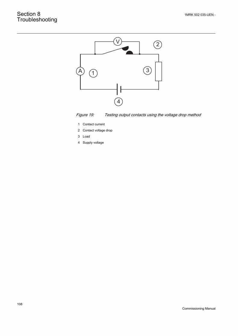
A1
2
3
4
V
GUID-BBAEAF55-8D01-4711-A71D-BBC76B60BA3D V1 EN
Figure 19: Testing output contacts using the voltage drop method
1 Contact current
2 Contact voltage drop
3 Load
4 Supply voltage
Section 8 1MRK 502 035-UEN -Troubleshooting
108Commissioning Manual
V1
2
A
GUID-31DF5495-91F1-4A4B-8FD5-50625038961E V1 EN
Figure 20: Testing a trip contact
1 Trip contact under test
2 Current limiting resistor
• To check the status of the output circuits driving the output relay via theLHMI, select Main menu/Tests/Binary output values/Binary outputmodules and then navigate to the board with the actual binary output to bechecked.
• Test and change the relay state manually.1. To set the IED to test mode, select Main menu/Tests/IED
testmode1:TESTMODE/TestMode and set the parameter to On.2. To operate or force the output relay to operate, select and then navigate
to the board with the actual binary output relay to be operated/forced.3. Select the BOn_PO to be operated/forced and use and or to
operate the actual output relay.In PCM600, only the result of these operations can be checked by right-clicking the product and selecting Signal Monitoring tool and then
1MRK 502 035-UEN - Section 8Troubleshooting
109Commissioning Manual
navigating to the actual I/O-board and the binary input in question. Theactivated output signal is indicated with a yellow-lit diode. EachBOn_PO is represented by two signals. The first signal in LHMI is theactual value 1 or 0 of the output, and in PCM600 a lit or dimmed diode.The second signal is the status Normal or Forced. Forced status is onlyachieved when the BO is set to Forced or operated on the LHMI.
Set the parameter TestMode to Off after completing thesetests. The Start LED stops flashing when the relay is nolonger in test mode.
An initially high contact resistance does not cause problems as it is reduced quicklyby the electrical cleaning effect of fritting and thermal destruction of layers,bringing the contact resistance back to the mOhm range. As a result, practically thefull voltage is available at the load.
Section 8 1MRK 502 035-UEN -Troubleshooting
110Commissioning Manual
Section 9 Glossary
AC Alternating current
ACT Application configuration tool within PCM600
A/D converter Analog-to-digital converter
ADBS Amplitude deadband supervision
AI Analog input
ANSI American National Standards Institute
AR Autoreclosing
ASCT Auxiliary summation current transformer
ASD Adaptive signal detection
AWG American Wire Gauge standard
BI Binary input
BOS Binary outputs status
BR External bistable relay
BS British Standards
CAN Controller Area Network. ISO standard (ISO 11898) forserial communication
CB Circuit breaker
CCITT Consultative Committee for International Telegraph andTelephony. A United Nations-sponsored standards bodywithin the International Telecommunications Union.
CCVT Capacitive Coupled Voltage Transformer
Class C Protection Current Transformer class as per IEEE/ ANSI
CMPPS Combined megapulses per second
CMT Communication Management tool in PCM600
CO cycle Close-open cycle
Codirectional Way of transmitting G.703 over a balanced line. Involvestwo twisted pairs making it possible to transmit informationin both directions
COMTRADE Standard format according to IEC 60255-24
Contra-directional Way of transmitting G.703 over a balanced line. Involvesfour twisted pairs, two of which are used for transmittingdata in both directions and two for transmitting clock signals
1MRK 502 035-UEN - Section 9Glossary
111Commissioning Manual
CPU Central processor unit
CR Carrier receive
CRC Cyclic redundancy check
CROB Control relay output block
CS Carrier send
CT Current transformer
CVT Capacitive voltage transformer
DAR Delayed autoreclosing
DARPA Defense Advanced Research Projects Agency (The USdeveloper of the TCP/IP protocol etc.)
DBDL Dead bus dead line
DBLL Dead bus live line
DC Direct current
DFC Data flow control
DFT Discrete Fourier transform
DHCP Dynamic Host Configuration Protocol
DIP-switch Small switch mounted on a printed circuit board
DI Digital input
DLLB Dead line live bus
DNP Distributed Network Protocol as per IEEE/ANSI Std.1379-2000
DR Disturbance recorder
DRAM Dynamic random access memory
DRH Disturbance report handler
DSP Digital signal processor
DTT Direct transfer trip scheme
EHV network Extra high voltage network
EIA Electronic Industries Association
EMC Electromagnetic compatibility
EMF (Electric Motive Force)
EMI Electromagnetic interference
EnFP End fault protection
EPA Enhanced performance architecture
ESD Electrostatic discharge
FCB Flow control bit; Frame count bit
Section 9 1MRK 502 035-UEN -Glossary
112Commissioning Manual
FOX 20 Modular 20 channel telecommunication system for speech,data and protection signals
FOX 512/515 Access multiplexer
FOX 6Plus Compact time-division multiplexer for the transmission ofup to seven duplex channels of digital data over optical fibers
G.703 Electrical and functional description for digital lines used bylocal telephone companies. Can be transported overbalanced and unbalanced lines
GCM Communication interface module with carrier of GPSreceiver module
GDE Graphical display editor within PCM600
GI General interrogation command
GIS Gas-insulated switchgear
GOOSE Generic object-oriented substation event
GPS Global positioning system
HDLC protocol High-level data link control, protocol based on the HDLCstandard
HFBR connectortype
Plastic fiber connector
HMI Human-machine interface
HSAR High speed autoreclosing
HV High-voltage
HVDC High-voltage direct current
IDBS Integrating deadband supervision
IEC International Electrical Committee
IEC 60044-6 IEC Standard, Instrument transformers – Part 6:Requirements for protective current transformers fortransient performance
IEC 61850 Substation automation communication standard
IEEE Institute of Electrical and Electronics Engineers
IEEE 802.12 A network technology standard that provides 100 Mbits/s ontwisted-pair or optical fiber cable
IEEE P1386.1 PCI Mezzanine Card (PMC) standard for local bus modules.References the CMC (IEEE P1386, also known as CommonMezzanine Card) standard for the mechanics and the PCIspecifications from the PCI SIG (Special Interest Group) forthe electrical EMF (Electromotive force).
IED Intelligent electronic device
1MRK 502 035-UEN - Section 9Glossary
113Commissioning Manual
I-GIS Intelligent gas-insulated switchgear
Instance When several occurrences of the same function are availablein the IED, they are referred to as instances of that function.One instance of a function is identical to another of the samekind but has a different number in the IED user interfaces.The word "instance" is sometimes defined as an item ofinformation that is representative of a type. In the same wayan instance of a function in the IED is representative of atype of function.
IP 1. Internet protocol. The network layer for the TCP/IPprotocol suite widely used on Ethernet networks. IP is aconnectionless, best-effort packet-switching protocol. Itprovides packet routing, fragmentation and reassemblythrough the data link layer.2. Ingression protection, according to IEC standard
IP 20 Ingression protection, according to IEC standard, level 20
IP 40 Ingression protection, according to IEC standard, level 40
IP 54 Ingression protection, according to IEC standard, level 54
IRF Internal failure signal
IRIG-B: InterRange Instrumentation Group Time code format B,standard 200
ITU International Telecommunications Union
LAN Local area network
LIB 520 High-voltage software module
LCD Liquid crystal display
LDD Local detection device
LED Light-emitting diode
MCB Miniature circuit breaker
MCM Mezzanine carrier module
MVB Multifunction vehicle bus. Standardized serial bus originallydeveloped for use in trains.
NCC National Control Centre
OCO cycle Open-close-open cycle
OCP Overcurrent protection
OLTC On-load tap changer
OV Over-voltage
Overreach A term used to describe how the relay behaves during a faultcondition. For example, a distance relay is overreachingwhen the impedance presented to it is smaller than the
Section 9 1MRK 502 035-UEN -Glossary
114Commissioning Manual
apparent impedance to the fault applied to the balance point,that is, the set reach. The relay “sees” the fault but perhaps itshould not have seen it.
PCI Peripheral component interconnect, a local data bus
PCM Pulse code modulation
PCM600 Protection and control IED manager
PC-MIP Mezzanine card standard
PISA Process interface for sensors & actuators
PMC PCI Mezzanine card
POR Permissive overreach
POTT Permissive overreach transfer trip
Process bus Bus or LAN used at the process level, that is, in nearproximity to the measured and/or controlled components
PSM Power supply module
PST Parameter setting tool within PCM600
PT ratio Potential transformer or voltage transformer ratio
PUTT Permissive underreach transfer trip
RASC Synchrocheck relay, COMBIFLEX
RCA Relay characteristic angle
RFPP Resistance for phase-to-phase faults
RFPE Resistance for phase-to-earth faults
RISC Reduced instruction set computer
RMS value Root mean square value
RS422 A balanced serial interface for the transmission of digitaldata in point-to-point connections
RS485 Serial link according to EIA standard RS485
RTC Real-time clock
RTU Remote terminal unit
SA Substation Automation
SBO Select-before-operate
SC Switch or push button to close
SCS Station control system
SCADA Supervision, control and data acquisition
SCT System configuration tool according to standard IEC 61850
SDU Service data unit
1MRK 502 035-UEN - Section 9Glossary
115Commissioning Manual
SMA connector Subminiature version A, A threaded connector with constantimpedance.
SMT Signal matrix tool within PCM600
SMS Station monitoring system
SNTP Simple network time protocol – is used to synchronizecomputer clocks on local area networks. This reduces therequirement to have accurate hardware clocks in everyembedded system in a network. Each embedded node caninstead synchronize with a remote clock, providing therequired accuracy.
SRY Switch for CB ready condition
ST Switch or push button to trip
Starpoint Neutral point of transformer or generator
SVC Static VAr compensation
TC Trip coil
TCS Trip circuit supervision
TCP Transmission control protocol. The most common transportlayer protocol used on Ethernet and the Internet.
TCP/IP Transmission control protocol over Internet Protocol. The defacto standard Ethernet protocols incorporated into 4.2BSDUnix. TCP/IP was developed by DARPA for Internetworking and encompasses both network layer and transportlayer protocols. While TCP and IP specify two protocols atspecific protocol layers, TCP/IP is often used to refer to theentire US Department of Defense protocol suite based uponthese, including Telnet, FTP, UDP and RDP.
TNC connector Threaded Neill-Concelman, a threaded constant impedanceversion of a BNC connector
TPZ, TPY, TPX,TPS
Current transformer class according to IEC
UMT User management tool
Underreach A term used to describe how the relay behaves during a faultcondition. For example, a distance relay is underreachingwhen the impedance presented to it is greater than theapparent impedance to the fault applied to the balance point,that is, the set reach. The relay does not “see” the fault butperhaps it should have seen it. See also Overreach.
U/I-PISA Process interface components that deliver measured voltageand current values
UTC Coordinated Universal Time. A coordinated time scale,maintained by the Bureau International des Poids et Mesures(BIPM), which forms the basis of a coordinated
Section 9 1MRK 502 035-UEN -Glossary
116Commissioning Manual
dissemination of standard frequencies and time signals. UTCis derived from International Atomic Time (TAI) by theaddition of a whole number of "leap seconds" to synchronizeit with Universal Time 1 (UT1), thus allowing for theeccentricity of the Earth's orbit, the rotational axis tilt (23.5degrees), but still showing the Earth's irregular rotation, onwhich UT1 is based. The Coordinated Universal Time isexpressed using a 24-hour clock, and uses the Gregoriancalendar. It is used for aeroplane and ship navigation, whereit is also sometimes known by the military name, "Zulutime." "Zulu" in the phonetic alphabet stands for "Z", whichstands for longitude zero.
UV Undervoltage
WEI Weak end infeed logic
VT Voltage transformer
X.21 A digital signalling interface primarily used for telecomequipment
3IO Three times zero-sequence current. Often referred to as theresidual or the earth-fault current
3UO Three times the zero sequence voltage. Often referred to asthe residual voltage or the neutral point voltage
1MRK 502 035-UEN - Section 9Glossary
117Commissioning Manual

118

119

Contact us
ABB ABSubstation Automation ProductsSE-721 59 Västerås, SwedenPhone +46 (0) 21 32 50 00Fax +46 (0) 21 14 69 18
www.abb.com/substationautomation
1MR
K 5
02 0
35-U
EN
-©
Cop
yrig
ht 2
011
AB
B. A
ll rig
hts
rese
rved
.