
1MRK 509 033-UEN ˇ ˆ ˙ · Voltage restrained time-overcurrent relays are mainly used as back-up...
49
*HQHUDO Voltage restrained time-overcurrent relays are mainly used as back-up phase short-circuit protection for genera- tors but in many other power system application are also possible. The protection must for selectivity against other protection relays often have a time delay of one second or more. Normal over-current relays can in many instances not be used since the generator synchronous reactance causes the sustained fault current to be lower than the rated load current of the machine. Other general uses of voltage restraint overcurrent relays including those application where otherwise impedance measurements are needed. The COMBIFLEX ® voltage restrained overcurrent protection RAISK is available in different variant for mea- surement of two- or three-phase currents. RAISK contains measuring relays RXISK 2H with two overcurrent stages. One voltage restrained overcurrent stage with five different inverse or definite time characteristics and one instantaneous high overcurrent stage. The operate current of the RAISK voltage restrained protection decreases with the voltage down to 25% of set operate current at full voltage. With normal settings the relay can therefore operate reliable even when the sus- tained short-circuit current is as low as 40% of generator rated current. The COMBIFLEX ® range of overcurrent relays is designed to meet the requirements for overcurrent and earth- fault protections in most power system applications, including those that require a special frequency response. For the general overcurrent application a very wide setting ranges are available with these relays, obviating the need to specify different versions and variants depending on the protective relay location of the protection or the voltage level of the power system. All RAISK protection assemblies are mounted in the COMBIFLEX ® modulaised system and are available with or without test switch, DC-DC converter or additional heavy duty tripping relays. 5;,6.DQG5$,6. 9ROWDJHUHVWUDLQHGRYHUFXUUHQWUHOD\ DQGSURWHFWLRQDVVHPEOLHV 1MRK 509 033-UEN Version 2 September 2001 8VHUV*XLGH
Transcript of 1MRK 509 033-UEN ˇ ˆ ˙ · Voltage restrained time-overcurrent relays are mainly used as back-up...

1MRK 509 033-UENVersion 2September 2001
Voltage restrained time-overcurrent relays are mainly used as back-up phase short-circuit protection for genera-tors but in many other power system application are also possible. The protection must for selectivity againstother protection relays often have a time delay of one second or more. Normal over-current relays can in manyinstances not be used since the generator synchronous reactance causes the sustained fault current to be lowerthan the rated load current of the machine. Other general uses of voltage restraint overcurrent relays includingthose application where otherwise impedance measurements are needed.
The COMBIFLEX® voltage restrained overcurrent protection RAISK is available in different variant for mea-surement of two- or three-phase currents.
RAISK contains measuring relays RXISK 2H with two overcurrent stages. One voltage restrained overcurrentstage with five different inverse or definite time characteristics and one instantaneous high overcurrent stage.
The operate current of the RAISK voltage restrained protection decreases with the voltage down to 25% of setoperate current at full voltage. With normal settings the relay can therefore operate reliable even when the sus-tained short-circuit current is as low as 40% of generator rated current.
The COMBIFLEX® range of overcurrent relays is designed to meet the requirements for overcurrent and earth-fault protections in most power system applications, including those that require a special frequency response.For the general overcurrent application a very wide setting ranges are available with these relays, obviating theneed to specify different versions and variants depending on the protective relay location of the protection or thevoltage level of the power system.
All RAISK protection assemblies are mounted in the COMBIFLEX® modulaised system and are available withor without test switch, DC-DC converter or additional heavy duty tripping relays.

Version 2
September 2001
1MRK 509 033-UEN
1.1 Description of safety signs........................................................... 31.1.1 The warning sign.......................................................................... 31.1.2 The note sign................................................................................ 31.1.3 Warning signs .............................................................................. 31.2 Note signs..................................................................................... 4
2.1 Three-phase or two-phase circuit protection................................ 52.2 Time characteristics ..................................................................... 52.3 Selectivity................................................................................... 112.4 Voltage restrained overcurrent relay RXISK 2H....................... 122.5 Demands on the measuring transformers................................... 132.5.1 Current transformers .................................................................. 142.5.2 Voltage transformers.................................................................. 15
4.1 Test switch ................................................................................. 184.2 DC-DC converter ....................................................................... 184.3 Measuring relay.......................................................................... 194.4 Tripping relay............................................................................. 19
5.1 Connection ................................................................................. 205.2 Settings....................................................................................... 215.3 Indication ................................................................................... 225.4 Tripping and Start Outputs......................................................... 235.5 ESD ............................................................................................ 235.6 Setting example.......................................................................... 23
!"#$%&
' "()& 7.1 Receiving and Handling............................................................. 337.2 Storage ....................................................................................... 33
$) * 8.1 Installation.................................................................................. 348.2 Testing........................................................................................ 378.3 Commissioning .......................................................................... 40
+
*
"
1MRK 509 033-UEN
Version 2September 2001
! "
! ! #$% The warning sign informs the user that certain operations should be avoid-ed in order to prevent human injuries or damage to equipment.
! !& #$ The note sign informs the user to be careful when using the product in cer-tain situations. It notifies the user of facts that could be of special interest during certain operations.
! !' (
! "#$%!

Version 2
September 2001
1MRK 509 033-UEN
!& )
the t
!
! #& ' (
' ! !
) *#+ ,)+*# -

1MRK 509 033-UEN
Version 2September 2001
& Voltage restrained time-overcurrent relays are used as phase-short circuitprotection for generators. When applying time overcurrent protection forgenerators, problems with low sustained fault current often occurs. Thelow fault current is caused by the generators synchronous reactance andcan in some cases be lower than the full load current. When using a volt-age restrained overcurrent protection the busbar voltage drop in case of anearby fault will lower the current operate value and reliable tripping issecured.
The availability of five different inverse time characteristics and the defi-nite time delay make the relays suitable for applications requiring co-ordi-nation with existing time-overcurrent relays. The low transient overreachand short recovery time ensures suitability for most applications, includ-ing those where otherwise impedance measurements used to be made.
&! #$*$%*$
In a three-phase protective relay, both phase currents are always measured when a two-phase fault occurs. The relay operates, therefore, even if oneof the measuring circuits is faulty. A three-phase protection is thereforemore dependable than a two-phase protection. Compared to a summatingtype of protection, that has a common measuring circuit, considerablygreater reliability is achieved.
As there always will be fault currents in at least one of the phases duringshort-circuit, it often is adequate to use two-phase protection in the feed-ers. It is absolutely necessary that the overcurrent relays are located in thesame two phases all over the network.
&!& #$ To achieve selective fault clearing the different protections and stagesmust have different time delays. Several different time characteristics areavailable. They are described below and some general guide-lines aregiven. However, as a general rule, different time characteristics should notbe used in one and the same system if not necessary. An appropriate char-acteristic is therefore chosen on the basis of previous practice.
,!The operate time is independent of the fault current magnitude. The calcu-lation of settings is easier then for inverse characteristic but the time delayoften will be unnecessary long. The short-circuit power should not varytoo much when using the definite-time characteristic.
$(!The operate time is dependent of the fault current and voltage magnitude.The voltage magnitude influence the operate time when it is between 25%to 100% of set voltage value Us. The inverse characteristic enables toimprove utilisation of the overload capability of the protected object.

Version 2
September 2001
1MRK 509 033-UEN
There are four standard inverse time curves, normal, very, extremely andlong-time inverse. The relationship between current and time on the stan-dard curves complies with the standard IEC 60255-3 and can generally beexpressed as:
where:
t = operating time in secondsk = settable inverse time factorI = measured current valueI> = set current value.U = measured voltage valueUs = set voltage value.α= index characterising the algebraic functionβ= constant characterising the relay
The different characteristics are determined by the values of the constantsα and β:
According to the standard IEC 60255-3 the normal current/voltage quotarange is defined as 2 - 20 times the setting. Additionally, the relay muststart at the latest when the current/voltage quota exceeds a value of 1,3times the set start value when the current-time characteristic is normalinverse, very inverse or extremely inverse. When the characteristic islong-time inverse, the normal range in accordance with the standard is 2 -7 times the setting and the relay has to start when the current exceeds 1,1times the setting.
The characteristics of the RXISK 2H satisfy the defined function in thestandard at least down to 1,3 times the setting.
tk β⋅
II>----- Us
U-------⋅
α1–
-----------------------------------=
+$ α β
Normal inverse 0,02 0,14
Very inverse 1,0 13,5
Extremely inverse 2,0 80,0
Long-time inverse 1,0 120,0

1MRK 509 033-UEN
Version 2September 2001
-(!Normal inverse characteristic is suitable in systems with a large variationin short-circuit power fault currents for different fault locations. The char-acteristic is shown in Fig. 1.
./
1 2 3 4 5 6 7 10 20 II>----- Us
U-------⋅
0.1
1
10
20
S
k=
1.10.9
0.7
0.5
0.3
0.1
0.05

Version 2
September 2001
1MRK 509 033-UEN
.(!The operate time is more dependent of the fault current magnitude. Thischaracteristic is suitable if there is a substantial reduction of fault currentas the distance from the power source increases. Very inverse gives asteeper curve than normal inverse and gives advantages in achievingselectivity between incoming and outgoing bays with small difference infault current. The characteristic is shown in Fig. 2
.
.0 1
1 2 3 4 5 6 7 10 20 II>----- Us
U-------⋅
0.1
1
10
20
S
k=1.10.90.7
0.05
0.5
0.3
0.1
0.05

1MRK 509 033-UEN
Version 2September 2001
/0(!The operate time is very dependent of the fault current and voltage magni-tude. This characteristic is intended for co-ordinating with fuses on distri-bution or industrial circuits. The characteristic is shown in Fig. 3.
.2 #
1 2 3 4 5 6 7 10 20 II>----- Us
U-------⋅
0.1
1
10
100S
k=
1.10.70.5
0.3
0.1
0.050.01

Version 2
September 2001
1MRK 509 033-UEN
1,(!This characteristic has the same current dependence as the Very inversecharacteristic. It is used when longer time delays are desired. The charac-teristic is shown in Fig. 4.
.3 *
1 2 3 4 5 6 7 10 20 II>----- Us
U-------⋅
0.1
1
10
200
S
k=
1.1
0.7
0.5
0.3
0.1
0.05
100
0.9

1MRK 509 033-UEN
Version 2September 2001
"$(!This characteristic is provided for applications requiring co-ordinationwith the original ASEA type RI electromechanical inverse time relays.The characteristic is shown in Fig. 5.
.4 -)
&!' In order to obtain selective tripping of the series connected breakers in thenetwork, the time delay setting must increase for each step towards theinfeed point. This means that the tripping times will be longer the higherup in the network the overcurrent relay is placed, but at the same time theshort-circuit currents are increasing. It is therefore important that the timeintervals between the different selectivity stages are the shortest possible.The minimum time interval between relays, to be selective to each other,is dependent of the following factors: the difference in pick up time of the
1 2 3 4 5 6 7 10 20 II>----- Us
U-------⋅
0.1
1
10
S
k=1.1
0.7
0.5
0.3
0.1
0.05
0.9
20

Version 2
September 2001
1MRK 509 033-UEN
relays, the circuit breaker opening time and the relay resetting time. If definite-time characteristic is used, 0.3 s is usually recommended as aminimum time interval when the same types of relays are used.
&!, &-
RXISK 2H has a start-, a low set stage- (IU>) and a high set stage- (I>>) functions. The relay has also two fully isolated binary inputs. Bin. 1 isused for external blocking of the IU> start and trip functions. Bin. 2 isused for resetting of the LEDs. The functions are activated when a voltageRL is applied to the binary inputs.
The start function of RXISK 2H operates instantaneously when the cur-rent/voltage quota exceeds the set value of IU>.
The current setting is determined by the loading capacity of the object andby the minimum fault current within the protected zone. The voltage set-ting is determined by the system voltage.
1234The time characteristic is selected according to the recommendation given above. The delay of the trip signal is set with consideration to the demand on selectivity and the thermal characteristics of the installation. Further-more, the settings should always be chosen so that the overcurrent relaystarts for at least two circuit-breakers in series in the case of a fault. In this manner, backup protection is obtained if the primary protection or the cir-cuit-breaker should fail to operate.
&!3$4The high set stage is instantaneous. The function can also be blockedwhenever necessary.
The highest function is normally set to act for nearby faults and large faultcurrents. The reach is dependent on the variations in the short-circuitpower and on the type of fault. Constant short-circuit power increases thepossibility of using the instantaneous function also in networks whichhave moderate impedances.
In the case of a transformer, a fault on the far side will never give rise to afault current that has a magnitude greater than a given value. An instanta-neous step, that has a higher operate value, has a well-defined reachtowards but not through the transformer.
To prevent the relay from measuring through the transformer, consider-ation must be taken to the following:
- The transient overreach of the relay due to a possible dc component inthe fault current
- Variations in the short-circuit impedance of the transformer due to thepositions of the tap changer

1MRK 509 033-UEN
Version 2September 2001
- The magnitude of switching-current surge
Normally, the impedance at the centre position of the tap changer is given with a few percents variation in the end positions. The instantaneous func-tion is therefore set to approximately 120% of the maximum fault current. In extreme cases, a little higher setting may be necessary.
In those cases where selectivity with instantaneous function cannot beachieved, it is possible to block the function.
&!. " $
To ensure reliable operation of the protection, the following requirementsmust be fulfilled.
To avoid failure to operate it must be assured that the current from the sat-urated current transformer is large enough for operation of the relay. Therated equivalent limiting secondary e.m.f., Eal should satisfy the followingrequirement:
) is the current set value of the relay, -is the secondary resistance ofthe secondary winding of the current transformer, - is the resistance ofthe a single secondary wire from the current transformer to the relay and5 is the actual burden of the current transformer. It must be observed thatwe consider only the single length of the secondary wire from the currenttransformer to the relay. This is valid when we study overcurrent protec-tion in high impedance earthed systems.
$(In the case of overcurrent relays with an inverse time characteristic, itgenerally applies that saturated current transformers result in longer trip-ping times. To avoid error in the time delay of the relay the current trans-former must not saturate for any possible fault current that can occur. Apractical value for RXISK 2H to chose is to assure that a current, 20 timesthe current setting of the inverse time function, does not give saturation.The rated equivalent limiting secondary e.m.f., Eal should satisfy the fol-lowing requirement:
) is the current set value of the inverse time function, -is the second-ary resistance of the secondary winding of the current transformer, -isthe resistance of the a single secondary wire from the current transformerto the relay and 5 is the actual burden of the current transformer.
$To avoid failure to operate, of the instantaneous function, it must beassured that the current from the saturated current transformer is largeenough for operation of the relay. The function should be assured for fault
Eal 2 Iset RCT Rl Zr++[ ]⋅ ⋅≥
Eal 20 Iset RCT Rl Zr++[ ]⋅ ⋅≥

Version 2
September 2001
1MRK 509 033-UEN
currents at least 1.5-2.0 times the value set on the relay. The margindepends on the time constant of the network. As a rule, the majority offault points in distribution networks have low time constants and thereforea margin of 1.5 times the set value should be sufficient. The rated equiva-lent limiting secondary e.m.f., Eal should, in this case, satisfy the follow-ing requirement:
) is the current set value of the instantaneous function, -is the sec-ondary resistance of the secondary winding of the current transformer, -
is the resistance of the a single secondary wire from the current trans-former to the relay and 5 is the actual burden of the current transformer.
* From the current transformer data the rated equivalent limiting secondarye.m.f., Eal can be calculated as:
6 is the rated symmetrical short circuit current factor, ) is the rated sec-ondary current of the current transformer, -is the secondary resistanceof the secondary winding of the current transformer, and $ is the ratedburden of the current transformer.
&!.! + In order to avoid the risk of extended operating time of the time-delayedphase short-circuit protection, caused by transient d.c. saturation of theCTs, the saturation factor n at actual CT burden should meet the require-ment:
where:
n = saturation factor at the actual burdenALF = accuracy limiting factor acc. to IEC 185Sn = rated burden of the CT (VA)S = actual burden in VA at rated current IsnR2 = resistance of the secondary winding of the CTIsn = rated secondary current of the CTI2g = rated secondary generator load current
For generators with sustained short-circuit current and I > function withinverse time delay, n > 20 is recommended.
Eal 1.5 Iset RCT Rl Zr++[ ]⋅ ⋅≥
Eal Kssc I⋅ n RCT
Sn
In2
------+⋅=
n ALFSn R2 Isn
2⋅+
S R2 Isn2⋅+
-------------------------------IsnI2g-------- 15>⋅ ⋅=
1MRK 509 033-UEN
Version 2September 2001
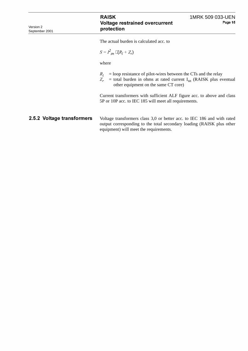
The actual burden is calculated acc. to
$7)⋅ (-85)
where
- = loop resistance of pilot-wires between the CTs and the relay 5 = total burden in ohms at rated current Isn (RAISK plus eventual
other equipment on the same CT core)
Current transformers with sufficient ALF figure acc. to above and class5P or 10P acc. to IEC 185 will meet all requirements.
&!.!& Voltage transformers class 3,0 or better acc. to IEC 186 and with ratedoutput corresponding to the total secondary loading (RAISK plus otherequipment) will meet the requirements.

Version 2
September 2001
1MRK 509 033-UEN
' /The RXISK 2H relays constitutes the measuring units of RAISK. Thesimplified functional diagram in Fig. 6 illustrates the mode of operatingfor the RXISK 2H relay. For setting of operate values and relays/LED’sfunctions, 3.
To provide a suitable voltage for the electronic measurement circuits therelays are provided a current-transformer and a voltage-transformer. Thevoltage from the current-transformer is shunted via dip-switches before itis filtered with a 4th order bandpass filter. The voltage from the voltage-transformer is filtered with a 2nd order bandpass filter with a centre fre-quency equal to 55 Hz. The current and voltage values are filtered with a moving average filter toreduce ripple.
.9 $ -:)$60;
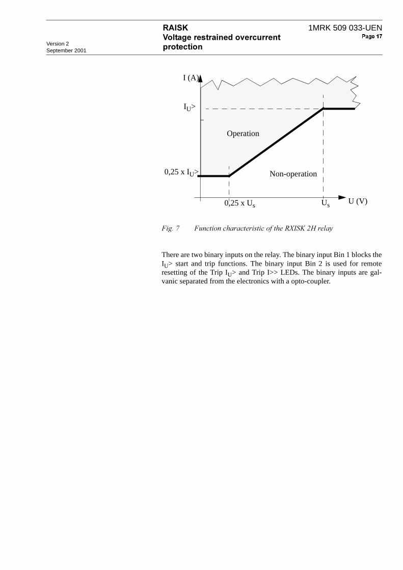
The RXISK 2H function characteristic is shown in Fig. 7. The RXISK 2Hstart IU> operates when the IU> value reaches the set operate values (1,0 - 3,0) x Is. For the IU> stage, inverse-time delay or definite-time delayis available.
IU>
k
I
start IU>
trip I>>
U
I
invNIVIEIRI
def124LI
trip I>>
trip IU>
start IU>
trip IU>
IUsU-------⋅
Us
IU ≥ IU> &
block
I ≥ I>>
1MRK 509 033-UEN
Version 2September 2001
.< . -:)$60;
There are two binary inputs on the relay. The binary input Bin 1 blocks theIU> start and trip functions. The binary input Bin 2 is used for remoteresetting of the Trip IU> and Trip I>> LEDs. The binary inputs are gal-vanic separated from the electronics with a opto-coupler.
Us
I (A)
U (V)0,25 x Us
Operation
Non-operation0,25 x IU>
IU>

Version 2
September 2001
1MRK 509 033-UEN
, "The protection assemblies are of protective class I equipment in which protection against electric shock does not rely on basic insulation only it also includes additional safety precautions in such way that accessible conductive parts are connected to protective earth.
The voltage restrained overcurrent protection RAISK is designed in anumber of variants for two- or three-phase overcurrent protections. Eachprotection is available with or without test switch RTXP 18, DC-DC con-verter RXTUG 22H or tripping relay RXME 18.
All protection assemblies are built up by modules in the COMBIFLEX®
modular system mounted on apparatus bars. The connections to the pro-tection assemblies are made by leads equipped with COMBIFLEX® sock-ets.
The type of modules and their physical position and the modular size ofthe protection are shown in the =>? and in the Circuit and Ter-minal Diagrams for each of respective protection. One or more of the fol-lowing modules can be included.
,! #%$ The test switch RTXP 18 is a part of the COMBITEST testing systemdescribed in the =>?, document 1MRK 512 001-BEN. A com-plete secondary testing of the protection can be performed by using a test-plug handle RTXP 18 connected to a test set. When the test-plug handle isinserted into the test switch, preparations for testing are automatically car-ried out in a proper sequence, i.e. blocking of tripping circuits, short-cir-cuiting of current circuits, opening of voltage circuits and making theprotection terminals available for secondary testing. RTXP 18 has themodular dimensions 4U 6C.
All input currents and voltages can be measured by a test plug RTXMconnected to a multi meter. The tripping circuits can be blocked by a trip-block plug RTXB and the protection can be totally blocked by a block-plug handle RTXF 18.
,!& "+*"+ The DC-DC converter RXTUG 22H converts the applied battery voltageto an alternating voltage which is then transformed, rectified, smoothedand in this application regulated to ± 24 V DC. The auxiliary voltage is inthat way adopted to the measuring relays. In addition, the input and outputvoltages will be galvanically separated, which contributes to damping ofpossible transients in the auxiliary voltage supply to the measuring relays.The converter has a built-in signal relay and a green LED for supervisionof the output voltage.
RXTUG 22H has the modular dimensions 4U 6C. It is described in the=>?, document 1MRK 513 001-BEN.

1MRK 509 033-UEN
Version 2September 2001
,!' / The voltage restraint time-overcurrent relay RXISK 2H consists mainly oftwo input transformers for current and voltage adoption and isolation, fil-ter circuits, digital-analog converter, microprocessor, MMI consisting of aprogramming switch and potentiometers for setting and LEDs for start,trip and in service indications, and three output relays, each with achange-over contact, for the start and trip functions of the restrained stageand for trip function of the non-voltage depending high set stage. Therelay has also two binary inputs for remote resetting of LED indicationsand for blocking the IU> start and trip functions.
A short circuiting connector RTXK is mounted on the rear of the terminalbase and will automatically short-circuit the current input when the relayis removed from its terminal base.
RXISK 2H has the modular dimensions 4U 6C.
,!, # The auxiliary relay RXME 18 can be included as a tripping relay whenheavy duty contacts are required. It has two heavy duty make contacts anda red flag. The flag will be visible when the armature picks-up. The flag ismanually reset by a knob in the front of the relay. Typical operate time is35 ms.
RXME 18 has the modular dimensions 2U 6C. It is described in the=>?, document 1MRK 508 015-BEN.
Version 2
September 2001
1MRK 509 033-UEN
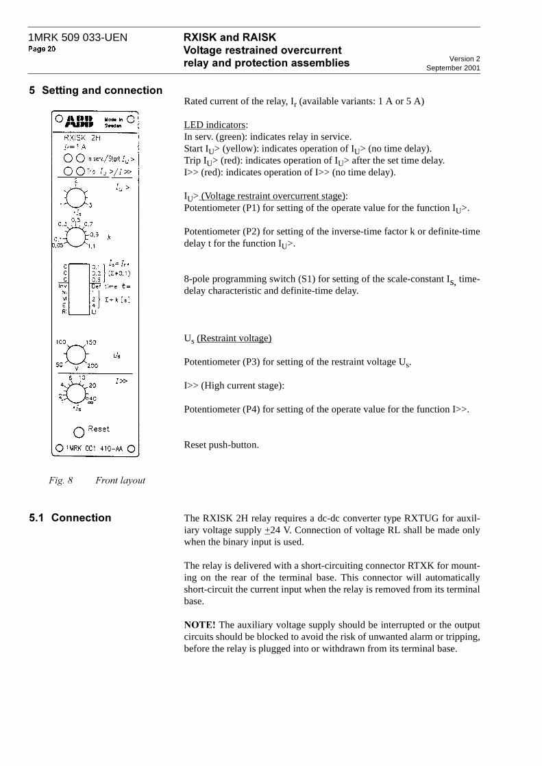
. Rated current of the relay, Ir (available variants: 1 A or 5 A)
LED indicators:In serv. (green): indicates relay in service.Start IU> (yellow): indicates operation of IU> (no time delay).Trip IU> (red): indicates operation of IU> after the set time delay.I>> (red): indicates operation of I>> (no time delay).
IU> (Voltage restraint overcurrent stage):Potentiometer (P1) for setting of the operate value for the function IU>.
Potentiometer (P2) for setting of the inverse-time factor k or definite-timedelay t for the function IU>.
8-pole programming switch (S1) for setting of the scale-constant Is, time-delay characteristic and definite-time delay.
Us (Restraint voltage)
Potentiometer (P3) for setting of the restraint voltage Us.
I>> (High current stage):
Potentiometer (P4) for setting of the operate value for the function I>>.
Reset push-button.
.@ .
.! + The RXISK 2H relay requires a dc-dc converter type RXTUG for auxil-iary voltage supply +24 V. Connection of voltage RL shall be made onlywhen the binary input is used.
The relay is delivered with a short-circuiting connector RTXK for mount-ing on the rear of the terminal base. This connector will automaticallyshort-circuit the current input when the relay is removed from its terminalbase.
-5 /6 The auxiliary voltage supply should be interrupted or the outputcircuits should be blocked to avoid the risk of unwanted alarm or tripping,before the relay is plugged into or withdrawn from its terminal base.

1MRK 509 033-UEN
Version 2September 2001
.A !
.!& All settings can be changed while the relay is in normal service.
!,$ The scale constant Is is equal to the rated current Ir times the sum of theset value of the switches S1:1, S1:2 and S1:3 plus 0,1. The setting range isfrom 0,1 to 1,0 × the rated current Ir.
!(($7( The operate value is set with potentiometer P1 according to IU> = P1 × Is.The setting range is (1 - 3) × Is.
!(( The voltage restraint overcurrent stage has six time characteristics, whichare programmed on the programming switches S1:4 to S1:8., Set the programming switch S1:4 to position "Def. time t=", where t=Σ+k.Switches S1:5 to S1:7 are used for the main adjustment, Σ = 0 - 7 s, andpotentiometer P2 is used for the fine adjustment k = 0,05 - 1,1 s. The min-imum time delay is 50 ms and the maximum time delay is 8,1 s.When selecting this characteristic, the position of switch S1:8 ("RI" or"LI") has no influence.$(, Set switch S1:4 in position "Inv". The inverse-time characteristic isselected with the switches S1:5 to S1:8 (NI = Normal Inverse, VI = VeryInverse, EI = Extremely Inverse, RI = ASEA RI-relay inverse, LI = Long-time Inverse).By setting the selector switch S1 a precedence order is applied, from top(S1:5) to bottom (S1:8). That is, if the "NI" characteristic is selected (theswitch in the left hand side position), it overrides the settings of switchesS1:6 to S1:8. Another example; if the "LI" characteristic shall be used, theswitches S1:5 to S1:8 must all be in the right hand side position.
111
112
113
324
325
331
341
117
110-220V
48-60V
0V
Iu>
Iu>
I>>
Ur0V
Ir
0A
114 115 116
+24V 0V -24V
121
122
123
110-220V
48-60V
0V
Bin1 Bin2
313315
314 120
RL
316318
317
326328
327
Ir
RL
Version 2
September 2001
1MRK 509 033-UEN
After setting the time characteristic, the time-delay is determined by thetime factor k, which is adjusted with potentiometer P2 and the magnitudeof the current.
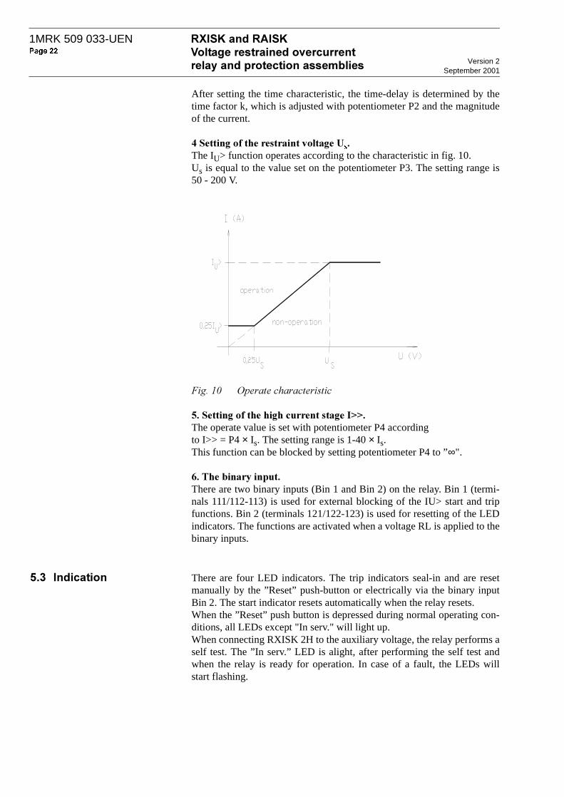
!(8 The IU> function operates according to the characteristic in fig. 10.Us is equal to the value set on the potentiometer P3. The setting range is50 - 200 V.
./B
!!!$77 The operate value is set with potentiometer P4 according to I>> = P4 × Is. The setting range is 1-40 × Is.This function can be blocked by setting potentiometer P4 to ”∞".
!9 There are two binary inputs (Bin 1 and Bin 2) on the relay. Bin 1 (termi-nals 111/112-113) is used for external blocking of the IU> start and tripfunctions. Bin 2 (terminals 121/122-123) is used for resetting of the LEDindicators. The functions are activated when a voltage RL is applied to thebinary inputs.
.!' There are four LED indicators. The trip indicators seal-in and are resetmanually by the ”Reset” push-button or electrically via the binary inputBin 2. The start indicator resets automatically when the relay resets.When the ”Reset” push button is depressed during normal operating con-ditions, all LEDs except "In serv." will light up.When connecting RXISK 2H to the auxiliary voltage, the relay performs aself test. The ”In serv.” LED is alight, after performing the self test andwhen the relay is ready for operation. In case of a fault, the LEDs willstart flashing.

1MRK 509 033-UEN
Version 2September 2001
.!, # 0
The RXISK 2H relay has one start and one delayed tripping output for thevoltage restraint overcurrent stage, and one tripping output for the highcurrent stage. Each output is provided with one change-over contact. Alloutputs reset automatically when the energising quantity passes the reset-ting value of the relay.
.!. 1" The relay contains electronic circuits which can be damaged if exposed tostatic electricity. Always avoid to touch the circuit board when the relaycover is removed.
.!2 3 The settings of the RAISK voltage restrained protection of the generatorin Fig. 11 shall be coordinated with the settings of the relays in line A, lineB and the transformer bay.
.// $
Line A: Overcurrent relay with Normal Inverse (NI) characteristic. Char-acteristic current setting: Ib = 480 A. Time multiplier setting: k = 0,3
Line B: Overcurrent relay with Normal Inverse (NI) characteristic. Char-acteristic current setting: Ib = 240 A. Time multiplier setting: k = 0,3
Transformer bay: Transformer differential relay
For coordination of RAISK against the relays in lines A and B, considerthe case when the transformer is out of service, and the total fault currentis delivered from the generator. The short-circuit current from the genera-tor for faults close to the bus and at the end of line A have been calculatedand are shown in Fig. 12.
G
RAISK >
200/5 A
400/5 A
F1
>
F2
Line A
Line B
ZA = 0,3 Ω
I/I>
40 mVAUk = 10 %
30 mVAX"
d = 15 %Xd = 100 %
I>
I>
(99000210.vsd)

Version 2
September 2001
1MRK 509 033-UEN
./0 $ ./.0
1Operate time of relay in line A:
Table below shows the short-circuit current as multiples of the set charac-teristic current Ib = 480 A.
0.2 0.4 0.6 0.8 1.0
2000
4000
6000
8000
10000
Ik (A)
t(s)1.2
12000
F1
F2
(99000211.vsd)
Time after fault ( s ) 0,0 0,2 0,4 0,6 0,8 1,0 1,2
Fault F1Fault current ( A ) Ratio Ik/Ib
11 55024
6 50013,5
4 4009,2
3 0006,25
2 2004,6
1 7303,6
1 7303,6
Fault F2Fault current ( A ) Ratio Ik/Ib
7 20015
4 5009,4
3 0006,25
2 5005,2
2 0004,2
1 6003,33
1 6003,33

1MRK 509 033-UEN
Version 2September 2001
Make an approximate estimation of the operate time of the relay in LineA, using the mean value of the fault current F1. Mean value for the timeperiod 0 - 1,2 s is 4 440 A. The ratio IF / Imean = 4 440 / 480 = 9,25. Withtime multiplier setting k = 0,3, the operate time acc. to the current/timecharacteristics in Fig. 1 is 0,9 s.
The operate time of the inverse time relay can with satisfactory accuracybe calculated by considering the increase of the content of the trip circuitmemory during short intervals and summing up until the content is 100per cent of the tripping level.
::;Consider fault current F1 and time period 0 - 0,2 s after the fault. Theaverage value of Ik/Ib = (24 + 13,5) / 2 = 18,75.
The corresponding operate time is
During the time interval of 0,2 s, the contents of the trip circuit memory isincreased by 100% x 0,2/0,696 = 29% of the operate value.
For the time period 0,2 - 0,4 s after the fault, the average value of Ik/Ib =(13,5 + 9,2) / 2 = 11,35.
The corresponding operate time is
and the increase of the contents in the trip circuit memory is 100% x 0,2/0,84 = 24%.
Making the same calculation for the other time intervals, the followingtable can be made up:
Hence, the operate time will be slightly shorter than 1,0 s.
::;The average value of the fault current during the time period 0 -1,2 s afterthe fault, Imean = 3 200 gives the ratio IF / Imean =3 200 / 480 =6,67. Theoperate time acc. to the current-time characteristics in Fig. 1 is about 1,1 s.
t0 3 0 14,×,
18 750 02,, 1–--------------------------------- 0 696s,= =
t0 3 0 14,×,
11 350 02,, 1–--------------------------------- 0 84s,= =
Time after fault ( s ) 0,0 - 0,2 0,2 -0,4 0,4 - 0,6 0,6 - 0,8 0,8 -1,0 1,0 -1,2
Increase of trip mem-ory content ( % )
29 24 20 16 14
Accumulated content in trip memory ( % )
29 53 73 89 103

Version 2
September 2001
1MRK 509 033-UEN
The more accurate calculation, using the ratios Ik/Ib in the table below gives the following result:
Hence the operate time is close to 1,2 s.
1<The operate time of the relay with setting Ib = 240 A in feeder B will beshorter than for the relay in feeder A.
;Phase short-circuits in the transformer will be tripped instantaneously bythe transformer differential relay.
("$%!
1. RAISK with independent time delay.
The independent time delay is set 0,3 s longer than the operate time of therelay in line A, i.e. 1,2 + 0,3 = 1,5 s.
The operate current IU is set above maximum short-time overload current.A typical setting is 1,4 times rated generator current.
Voltage Us can be set to 90% of rated generator voltage to give extra mar-gin against unwanted operation due to over-load current.
2. RAISK with inverse time delay
Characteristic current at rated voltage IU is normally set to 1,4 x rated gen-erator current. Setting: IU = 1,4 x 1732 = 2400 A.
US is set to rated voltage = 10 kV
In case of a nearby phase short-circuit (F1), the phase-to-phase voltage toRAISK becomes nearly zero. Even for fault F2, the voltage to RAISKbecomes less than 25% of the set voltage US during large part of thefaulted time. Hence, the ratio between the fault current Ik and IU x 25/100is used when calculating the inverse time delay.
IU’ = IU x 25/100 = 2 400 x 25/100 = 600 A.
Time after fault ( s ) 0,0 - 0,2 0,2 -0,4 0,4 - 0,6 0,6 - 0,8 0,8 -1,0 1,0 -1,2
Increase of trip mem-ory content ( % )
24,4 20 17 15 13 11,6
Accumulated content in trip memory ( % )
44,4 61,4 76,4 89,4 101

1MRK 509 033-UEN
Version 2September 2001
Fault F1:
The operate time of RAISK should be 1,0 + 0,3 =1,3 s.
Make an approximate calculation of the operate time of RAISK, using themean value of the fault current F1. Mean value for the time period 0 - 1,4 s is 4 100 A.
The ratio Imean / IU’ = 4 100 / 600 = 6,84. According to the current/timecharacteristics in Fig. 1, current multiplier setting k = 0,4 gives time delayabout 1,4 s.
The more accurate calculation using the technique acc. to above, is rec-ommended. Try the reduced current multiplier setting k = 0,35
Fault F1. k = 0,35
Hence, the more accurately calculated operate time with k = 0,35 isslightly less than 1,5 s.
Fault F2.
The reduced short-circuit current compared to F1 gives an operate time ofmore than 1,5 s.
Select setting k = 0,35
Setting of high set stage I>>:
Stage I>> shall be blocked, since there is no significant differencebetween the fault current in case of faults on the generator bus and close-up faults on the lines.
Time after fault ( s ) 0,0 0,2 0,4 0,6 0,8 1,0 1,2 1,4
Fault F1Fault current ( A ) Ratio Ik/IU’
11 55019,3
6 50010,8
4 4007,3
3 0005,0
2 2003,67
1 7302,88
1 7302,88
17302,88
Fault F2Fault current ( A ) Ratio Ik/IU’
7 20012
4 5007,5
3 0005,0
2 5004,17
2 0003,33
1 6002,67
1 6002,67
16002,67
Time after fault ( s ) 0,0 -0,2 0,2 -0,4 0,4 -0,6 0,6 -0,8 0,8 -1,0 1,0 -1,2 1,2 -1,4
Increase of trip mem-ory content ( % )
23 18,4 15 12,2 9,8 8,7 8,7
Accumulated content in trip memory ( % )
23 41,4 56,4 68,6 78,4 87,1 95,8

Version 2
September 2001
1MRK 509 033-UEN
2 #$ &-
Rated voltage Ur 120 V
Rated current Ir 1 A or 5 A
Scale constant Is 0,1, 0,20, 0,4 and 1,0 A0,5, 1,0, 2,0 and 5,0 A
Effective voltage range 0-300 V
Effective current range (0,25-60) x IsRated frequency frOperating frequency range
50-60 Hz45-66 Hz
Power consumption for:U = Ur =120 V
1 A variant I = Is = 0,1 AI = Is = 1 A
5 A variant I = Is = 0,5 AI = Is = 5 A
0,25 VA
0,5 mVA 50 mVA 1,5 mVA 100 mVA
Overload capacity voltage:continuouslyduring 10 s
Overload capacity current:1 A variant continuously5 A variant continuously1 A variant during 1 s5 A variant during 1 s
250 V300 V
4 A20 A100 A350 A
Function Stage IU>
Setting range IU> (1,0-3,0) x Is
Setting range Us 50-200 V
Voltage restraint characteristic See figure 11
Operate time, typical 50 ms
Reset time, typical 60 ms
Reset ratio, typical 90%
Transient over-reach L/R = 10, 50 and 100 ms < 3%
Overshoot time < 35 ms
Recovery time < 60 ms
Frequency dependence 45-65 Hz < ± 5%
Influence of harmonics in:U 100/120 Hz, 20%
150/180 Hz, 20%250/300 Hz, 20%
I 100/120 Hz, 20%150/180 Hz, 20%250/300 Hz, 20%
< 4%< 8%< 2%
< 6%< 8%< 3%

1MRK 509 033-UEN
Version 2September 2001
0
Function Stage I>>
Setting range (1,0 - 40) x Is and ∞Operate time, typical
I = 0 => 3 x I>> I = 0 => 20 x I>>
35 ms25 ms
Reset time, typicalI = 3 => 0 x I>>I = 20 => 0 x I>>
50 ms65 ms
Consistency of operate value < 2%
Reset ratio > 90%
Transient over-reach, L/R = 10, 50 and 100 ms < 3%
Overshoot time < 25 ms
Frequency dependence 45 - 65 Hz < ±5%
Influence of harmonics in:I 100 / 120 Hz, 20%
150 / 180 Hz, 20%250 / 300 Hz, 20%
< 3%< 6%< 3%
#
Time delay Inverse and definite time(Normal, Very, Extremely, Long time and RI inverse time)
Setting range Definite timeInverse time
0,05-8,1 sk = 0,05-1,1
Accuracy Definite time
Inverse time
Consistency
The tolerances for inverse and definite time delay are calculated under the condition that the current before operation was 0 x Is.
1% and ±50 ms
NI, VI, EI and LI 2 x op. value 12,5% and ±30 msNI, VI, EI and LI 5 x op. value 7,5% and ±30 msNI, VI, EI and LI 10 x op. value 5% and ±30 msNI, VI and LI 20 x op. value 5% and ±30 msEI 20 x op. value 5% and +80 -30 ms
RI 1,0 x op. value1 2,5% and ±30 ms1,3 x op. value1 2,5% and ±30 ms1,5 x op. value 5% and ±30 ms10 x op. value 5% and ±30 ms20 x op. value 5% and ±30 ms
< 0,5%
3"+
Auxiliary voltage EL for RXTUG 22HAuxiliary voltage to the relay
24-250 V DC, ±20%±24 V (from RXTUG 22H)
Power consumptionat RXTUG 22H input 24-250 V, before operation after operation
without RXTUG 22H±24 V, before operation
after operation
Max. 3,5 WMax. 4,5 W
Max. 1,5 WMax. 2,5 W
4
Binary input voltage RL 48-60 V and 110-220 V DC, -20% to +10%
Power consumption48-60 V110-220 V
Max. 0,3 WMax. 1,5 W

Version 2
September 2001
1MRK 509 033-UEN
0
Contacts 3 change-over
Maximum system voltage 250 V AC / DC
Current carrying capacitycontinuousduring 1 s
5 A15 A
Making capacity at inductive load with L/R >10 ms
during 200 msduring 1 s
30 A10 A
Breaking capacityAC, max. 250 V, cos ϕ > 0,4DC, with L/R < 40 ms, 48 V
110 V220 V250 V
8 A1 A0,4 A0,2 A0,15 A
151/+67All tests are performed together with the DC/DC-converter, RXTUG 22H
Surge immunity 1 and 2 kV, normal service2 and 4 kV, destructive test
IEC 61000-4-5, class 3IEC 61000-4-5, class 4
AC injection 500 V, AC SS 436 15 03, PL 4
Power frequency field immunity 1000 A/m IEC 61000-4-8
1 MHz burst 2,5 kV IEC 60255-22-1, class 3
Spark 4-8 kV SS 436 15 03, PL 4
Fast transient 4 kV IEC 60255-22-4, class 4
Electrostatic discharge In normal service with cover on 8 kV (contact)
15 kV (air)8 kV, indirect application
IEC 60255-22-2, class 4IEC 60255-22-2, class 4IEC 61000-4-2, class 4
Radiated electromagnetic field 10 V/m, 26-1000 MHz IEC 61000-4-3, Level 3
Conducted electromagnetic 10 V, 0,15-80 MHz IEC 61000-4-6, Level 3
Interruptions in auxiliary voltage110 VDC, no resetting for inter-ruptions
2-200 ms< 100 ms
IEC 60255-11
151/+67
Test Severity Standard
Conducted 0,15-30 MHz, class A EN 50081- 2
Radiated emission 30-1000 MHz, class A EN 50081- 2
+1*
#
EN 50082-2 Immunity
EN 50081-2 Emission
EN 50178 Low voltage directive

1MRK 509 033-UEN
Version 2September 2001
Dielectric testcurrent circuitother circuitsover open contact
2,5 kV AC, 1 min2,0 kV AC, 1 min1,0 kV AC, 1 min
IEC 60255-5
Impulse voltage test 5 kV, 1,2/50 µs, 0,5 J IEC 60255-5
Insulation resistance > 100 MΩ at 500 V DC IEC 60255-5
/$
Vibration Response: 2,0 g, 10-150-10 HzEndurance: 1,0 g, 10-150-10 Hz, 20 sweeps
IEC 60255-21-1, class 2IEC 60255-21-1, class 1
Shock Response: 5 g, 11 ms, 3 pulsesWithstand: 15 g, 11 ms, 3 pulses
IEC 60255-21-2, class 1
Bump Withstand: 10 g, 16 ms, 1000 pulses IEC 60255-21-2, class 1
Seismic X axis: 3,0 g, 1-35-1 HzY axis: 3,0 g, 1-35-1 HzZ axis: 2,0 g, 1-35-1 Hz
IEC 60255-21-3, class 2, extended (Method A)
#
Climatic condition Partially weather protected locations, switchgear envi-ronment, class 3K3
Storage -20 °C to +70 °C
Permitted ambient temperature -5 °C to +55 °C
($
Equipment Weight Height Width
RXISK 2H without RXTUG 22H 0,7 kg 4U 6C

Version 2
September 2001
1MRK 509 033-UEN
8 7-
8! -
Remove the protection package from the transport case and make a visualinspection for transport damages. Check that all screws are firmly tight-ened and all relay elements are securely fastened.
Check that all units are included in accordance with the apparatus list.
Normal ESD (Electrostatic Discharge) precautions for microprocessorrelays should be observed when handling the relays.
8!& If the protection package is to be stored before installation, this must bedone in a dry and dust-free place, preferably in the original transport case.
1MRK 509 033-UEN
Version 2September 2001
9 7# +
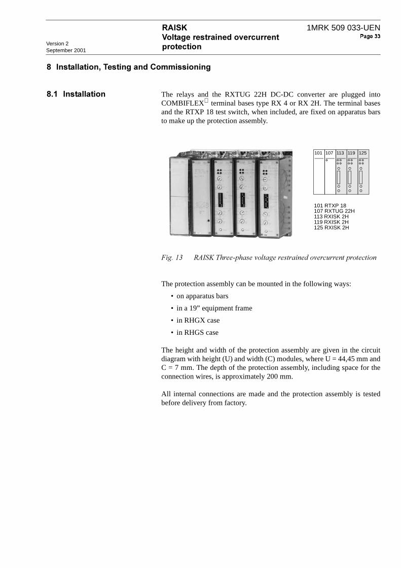
9! The relays and the RXTUG 22H DC-DC converter are plugged intoCOMBIFLEX terminal bases type RX 4 or RX 2H. The terminal basesand the RTXP 18 test switch, when included, are fixed on apparatus barsto make up the protection assembly.
./2 -)$6!
The protection assembly can be mounted in the following ways:
• on apparatus bars
• in a 19” equipment frame
• in RHGX case
• in RHGS case
The height and width of the protection assembly are given in the circuitdiagram with height (U) and width (C) modules, where U = 44,45 mm andC = 7 mm. The depth of the protection assembly, including space for theconnection wires, is approximately 200 mm.
All internal connections are made and the protection assembly is testedbefore delivery from factory.
113107101 119 125
101 RTXP 18107 RXTUG 22H113 RXISK 2H119 RXISK 2H125 RXISK 2H

Version 2
September 2001
1MRK 509 033-UEN
/=Detailed information on the COMBIFLEX connection and installationcomponents are given in Catalogue 1MRK 513 003-BEN. Information onthe relay mounting system is given in catalogue 1MRK 514 001-BEN
./3 -;?$
./4 -;?:
./9 /ACD
Case RHGS "&> +? 9 This type of case can be used for all com-mon ways of mounting. The RHGS cases are available in three different sizes, which can be combined with mounting accessories to get maximum flexibility. The cases can also be combined together with the protections in the 500 range.
(SE 970103)
RHGX 8
(SE 81702)
"&>#!,,!The RHGX cases are available in five sizes. The case, a metal box open at the back, has a flange (with a rubber sealing strip) at the front which acts as a stop when the case is inserted into a front panel opening. At the front of the case there is a door with a window and a rub-ber seal.
Size: 4U 19”+?=These types of equipment frames are used for cubicle mounting or panel mounting of plug-in units in the COMBIFLEX range. The frames are available in 3 sizes:
4U (17” x 19”)
8U (14” x 19”)
12U (21” x 19”)
for mounting 20, 40 and 60 module seats respectively.
(SE 96399)

1MRK 509 033-UEN
Version 2September 2001
*The external connections (dotted lines on the terminal and circuit dia-grams) are made with leads with 20 A COMBIFLEX sockets to theRTXP 18 test switch and with 10 A sockets to the relay terminal bases.
Each unit in the protection assembly has a unique item designation. Theitem designations are based on a coordinate system of U and C modules,where the first figure stands for the U module position starting from thetop and the next two figures stand for the C module position, starting fromthe left-hand side - seen from the front side of the protection assembly.The RTXP test switch in Fig. 19 has item designation 101, where the firstfigure stands for the U module position and the next two figures stand forthe C module designation.
The terminal designations include the item designation number of the unitfollowed by the terminal number marked on the rear of the terminalsocket.
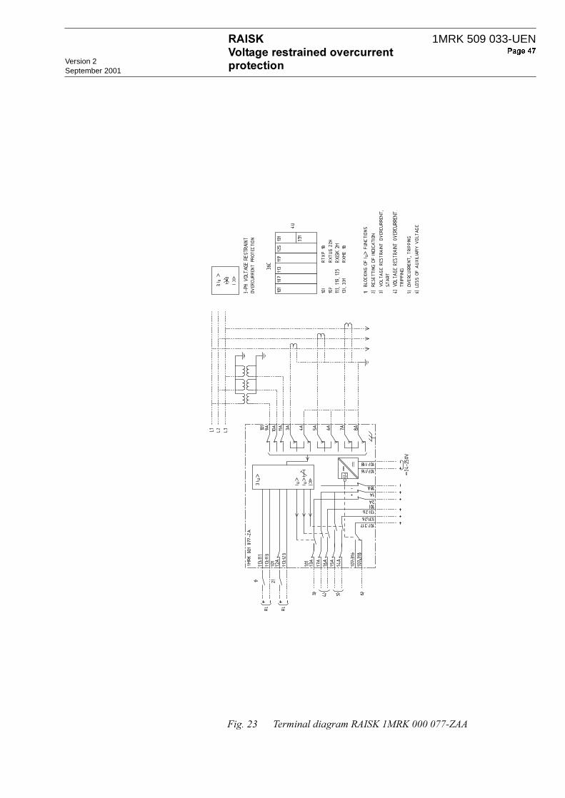
1) Blocking of Iu> functions 4) Voltage restraint overcurrent, 2) Resetting of indication tripping3) Voltage restraint overcurrent, 5) Overcurrent, tripping
start 6) Loss of auxiliary voltage
./< !/&-6BB/B<<5

Version 2
September 2001
1MRK 509 033-UEN
For plug-in units size 2H an additional figure 1 or 3 defines if the terminalis in the upper resp. lower part of the assembly. Compare terminal desig-nations 107:118 and 107:318 in Fig. 19.
Fig. 19 shows the rear of protection assembly RAISK, Order No. 1MRK001 076-ZA. The position of the terminals, which are used for externalconnections acc. to terminal diagram 1MRK 001 077-ZAA, is shown.
./@ * /&-6BB/B<<5
9!& # @The protection assemblies can be provided with the COMBITEST testswitch type RTXP 18.
When the test-plug handle RTXP 18 is inserted in the test switch, prepara-tions for testing are automatically carried out in the proper sequence, i.e.blocking of tripping circuits, short-circuiting of CT’s, opening of VT cir-cuits, making relay terminals accessible for testing.
When the test handle is in the intermediate position, only the tripping cir-cuits are opened. When the test handle is fully inserted, the relay is com-pletely disconnected from the instrument transformers and ready forsecondary injection testing.
Relays which are not provided with test switch have to be tested in theproper way from external circuit terminals.
The protection assemblies dealt with in this User’s Guide are made up ofseparate measuring units for each phase current and, when included,earth-fault current. Protection assemblies phase current relays can conve-
2 1 2 1 2 1
2 1 2 1 2 1
101:1A101:2A
101:11A101:12A
101:14A101:15A101:16A101:17A101:18A
107:316107:317107:318
119 113 107 101
113:123107:116107:118
331
101:7A101:8A
101:5A101:6A
331:26
125
2 1
2 1
101:3A101:4A
131
2 1
131:26
2 1
125:26
325:26
101:13A
101:9A101:10A
113:111113:113

1MRK 509 033-UEN
Version 2September 2001
niently be tested with a single-phase test set, e.g. the SVERKER test setwith built-in timer. They are however, more conveniently tested with athree-phase test set, e.g. the FREJA computer-aided test set with three-phase current and three-phase voltage output.
9=;• Test set SVERKER
• Multimeter or Ammeter, Class 0,5 or better
• RTXH 18 test plug with test leads
Fig. 20 shows as an example the connection of test set SVERKER for sec-ondary testing of the 3-phase overcurrent protection RAISK 4, Connec-tion Diagram 1MRK 001 077-ZAA. When testing, even the actual circuitdiagram of the protection, which shows the internal connections, shouldbe available.
When testing protections with voltage restrained relays RXISK 2H, avoltage should be applied to each individual phase of RXISK relay whentesting the voltage restraint over-current function (IU>).
Connect the test set and the ammeter acc to Fig. 20 to test the relayfunctions for phase L1 and insert the test-plug into the test switch. Auxil-iary voltage shall be connected to terminals 101:1A and 101:18A. Inter-connect terminals 1 and 2 on the test handle to get output voltage to testterminal 13 when the start function is activated. Connect auxiliary voltage(+) to terminals 131:26 and 331:26

Version 2
September 2001
1MRK 509 033-UEN
./A */ -!:;/@
Make the appropriate settings of relay operate currents, time delays andthe function of the digital input. Guide for the setting of the switches andpotentiometers on the front of the relays is given in Section 4, Settings andconnection.
Apply test voltage = Us on the voltage input. Increase the injection cur-rent until the low set stage start relay (IU>) for phase L1 operates (outputvoltage on test terminal 13). Check also the restraint level by injectinghalf the current measured above in the current input and decrease the volt-age until the low set stage start relay (IU>) for phase L1 operates. Themeasured voltage level should be half the set restraint level. Check alsothat the LED indicator for start is activated when IU> operates. Check theresetting values. Check the current operate value at test voltage U = 25%of Us. Check the drop-out value.
0-120V AC
3A3B
13B
17B
16B
15B
14B
U<
101
113:123
1MRK 001 077-ZA
107:
317
2B331:
26
131:
26
1A 18A
107:
116
107:
118
101
A A A B
A
B
107:316107:318
A1-100A AC
STOPTIMER
C
C
C
Test apparatusSVERKER
BA
B
4A4B5A5B6A6B7A7B8A8B
Iu7
I77
Iu7
3Iu7 9B10B
V
11B10112B
113:113A
B
113:111
1MRK 509 033-UEN
Version 2September 2001
Move the timer stop wire from test terminal 13 to test terminal 17. Ifdefinite time delay is selected, increase the current to twice the operatevalue of IU> and check the time delay. If inverse time delay is selected,check the operate time at two points on the inverse time characteristic, e.g.at twice and ten times the operate value of IU>. Check that the LED indi-cator for time delayed tripping is activated. Check that trip output isobtained on test terminal 16 when auxiliary voltage is connected to termi-nal 131:26.
Move the timer stop wire to test terminal 15 and check the operate cur-rent of stage I>>. Increase the current to twice the operate value and checkthe time delay. Check that the LED indicator for high current stage trip-ping is activated. Check that trip output is obtained on test terminal 14when auxiliary voltage is connected to terminal 331:26. Check the reset-ting value.
Check that the IU> function is blocked when voltage RL is applied to ter-minals 111-112 of the RXISK relay.
Connect the injection voltage and current to the appropriate test termi-nals and check the measuring elements of phase L2 and L3 in the sameway as for phase L1
9!' + The commissioning work includes check of all external circuits connectedto the protection and check of current ratio for the CTs and voltage ratiofor the VTs.
The DC circuits and tripping circuits should be checked, including opera-tion of the circuit breaker(s).

Version 2
September 2001
1MRK 509 033-UEN
: /The maintenance of the protection is divided into two chapters, preventive maintenance and corrective maintenance.
:! ;
Under normal operating conditions and when the surrounding atmosphere is of a non-corrosive nature no special maintenance is required. Preventive maintenance test of the protection assembly is recommended to be per-formed every four to five years. The tests can be performed more or less detailed. Instructions from utility power network company and other main-tenance directives, valid for maintenance of the power system, must be fol-lowed.
D!E
Switch-off and on the auxiliary DC supply to the protection. During thestart-up sequence the relay verifies the following.
When the processor starts it executes a self test sequence. If the processorfails to start in a proper way the LEDs will indicate by flashing accordingto figure below or the “In serv.” LED will not be lit. The program in themicroprocessor is executed in a fixed loop with a constant looptime. Theloop is supervised by an internal watch dog which initiates a programrestart if the program malfunctions.
*!E!9
The reset button has two functions, LED check and resetting the LEDs.When the button is depressed, the “Start IU>”, “Trip IU>” and “Trip I>>”LEDs are lit and the “In serv.” LED is switched off, in order to check theLEDs. When the button is released the “Start IU>”, “Trip IU>” and “TripI>>” LEDs are reset to show the actual status and “In serv.” LED is relit.
9!0
In exceptional cases, burned contacts on the auxiliary output relays can be dressed with a diamond file.
D
Additional tests can be selected from the secondary injection test. Seechapter “Installation, Testing and Commissioning” on page 33.
#<= # =
Config registers All LEDs flash in clockwise rotation
RAM “Trip Iu>” flashes
ROM “Trip I>>” flashes
A/D “Trip Iu>” and “Trip I>>” flash

1MRK 509 033-UEN
Version 2September 2001
:!& +
Corrective maintenance is required if the protection should be suspected to have made an unwanted operation or missed to clear a fault situation. In a case of an unwanted or missed fault clearing operation, the check list may help the user to recognize the wrong behavior of the protection assembly. If the check list below does not help, please contact the local ABB office for further technical support.
*!E!F(?1/!"# 8>&
If the “in service” LED is dark, the self supervision in the DC/DC-converter has recognized an internal fault.
Check the connection and polarity of the auxiliary input cables. Disconnect the output load from the DC/DC-converter.Measure both the input (24-250V DC) and output (+/-24V DC) voltages from the DC/DC-converter.
*!E!F(?1/!
If the “in service” LED is dark or any of the other LED’s are flashingthe self supervision in the relay has recognized an internal fault.
Check the internal connections between the DC/DC-converter and themeasuring relay (+/-24V DC).
*!E!
$!0!
Check that all screws in the COMBIFLEX© relay socket are tightly fas-tened and also check the internal and external cable connections to thetransformers.
!9
Check the connection and polarity of the involved binary inputs. Seechapter “Installation, Testing and Commissioning” on page 33
3.1.2 Check the settings
Check that all protection settings are correctly implemented in the relayaccording to the relay system plan.
*!E!
Verify the calculated setting values for the relay according to the networkconditions.

Version 2
September 2001
1MRK 509 033-UEN
$!0!
!!
Check the internal connections between the output relay and the auxiliaryoutput tripping relay. Check also the external connections from the trip-ping relay to the circuit-breaker coil.

1MRK 509 033-UEN
Version 2September 2001
> +
The tables below show the different variants of the voltage restrainedovercurrent protection RAISK.
# ?#%$
"+*"+*
#
0 )! />>
+" />>
# />>
"
RAISK 2 IU> x 076-GA 077-GA 077-GAA On request
RAISK 2 IU> x 076-HA 077-HA 077-HAA On request
RAISK 2 IU> x x 076-KA 077-KA 077-KAA On request
RAISK 2 IU> x x x 076-LA 077-LA 077-LAA Fig. 21,22
RAISK 3 IU> x 076-NA 077-NA 077-NAA On request
RAISK 3 IU> x 076-YA 077-YA 077-YAA On request
RAISK 3 IU> x x 076-PA 077-PA 077-PAA On request
RAISK 3 IU> x x x 076-ZA 077-ZA 077-ZAA Fig. 23,24

Version 2
September 2001
1MRK 509 033-UEN
.0B -)$6/&-6BBBB<<*

1MRK 509 033-UEN
Version 2September 2001
.0/ !-)$6/&-6BBBB<<*

Version 2
September 2001
1MRK 509 033-UEN
.00 -)$6/&-6BBBB<<5
1MRK 509 033-UEN
Version 2September 2001
.02 !-)$6/&-6BBBB<<5

Version 2
September 2001
1MRK 509 033-UEN
# .(
# =
#&=
#'=
#,=7@
#.=7
Customer: .....................................................
Station: .........................................................
Tested by: .................................................... Date: ........................................
Approved by: ................................................ Date: ........................................
Protected object : ...............................................................................
Relay position : ...............................................................................
Rated phase current Ir : ................................................................................
& '
Voltage restraint overcurrent Iu> : ................. : ................. : .................
Inverse characteristic. : ................. : ................. : ..................
Time : ................. : ................. : ..................
Restraint voltage Us : ................. : ................. : ..................
High current stage, I>> : ................. : ................. : ..................
A! ;$ ;$& ;$'
Pick-up Drop-out Pick-up Drop-out Pick-up Drop-out
U = Us ............. ............. ............ ............. ............. .............
U = 0.25 x Us ............. ............. ............ ............. ............. .............
A! ;$ ;$& ;$'
Pick-up Drop-out Pick-up Drop-out Pick-up Drop-out
I = 0.5 x op. val. ............. ............. ............ ............. ............. .............
1MRK 509 033-UEN
Version 2September 2001
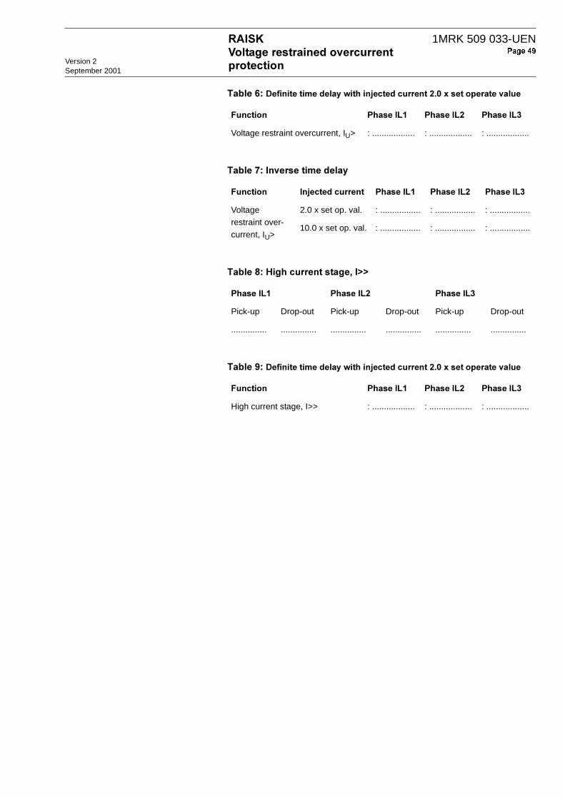
#2=" %$A &!>3
#8=
#9=-$7@@
#:=" %$A &!>3
? ;$ ;$& ;$'
Voltage restraint overcurrent, IU> : .................. : .................. : ..................
? A ;$ ;$& ;$'
Voltage restraint over-current, IU>
2.0 x set op. val. : ................. : ................. : .................
10.0 x set op. val. : ................. : ................. : .................
;$ ;$& ;$'
Pick-up Drop-out Pick-up Drop-out Pick-up Drop-out
............... ............... ............... ............... ............... ...............
? ;$ ;$& ;$'
High current stage, I>> : .................. : .................. : ..................


![User’s Manual HV/Collect*2 - ABB...[drive]:\sc\lib4\base\bbone\use\path4_s11.txt 14 1MRK 511 022-UEN*2.2-01 System setup Installation Instructions 2.3 Installation of Disturbance](https://static.fdocuments.in/doc/165x107/60b0a51539cf5477e7272d33/useras-manual-hvcollect2-abb-drivesclib4basebboneusepath4s11txt.jpg)