1986 NA,TID,NAL RADIO SCIENCE MEETING
326
1986 NA,TID,NAL RADIO SCIENCE MEETING International Union of Radio Science PROGRAM AND ABSTRACTS June 8-13, 1986 Wyndham Franklin Plaza Hotel II.I Philadelphia, PA •
Transcript of 1986 NA,TID,NAL RADIO SCIENCE MEETING
1986 NA,TID,NAL RADIO SCIENCE MEETING International Union of Radio Science
PROGRAM AND ABSTRACTS
June 8-13, 1986
Wyndham Franklin Plaza Hotel II.I Philadelphia, PA •

---~-------~--- ··------------- ---------
TECHNICAL PROGRAM SUMMARY
TIME ROOM MONDAY, JUNE 9 TUESDAY. JUNE 10 WEDNESDAY, JUNE 11 THURSDAY, JUNE 12 FRIDAY, JUNE 13
WYNDHAM A AP01 PHASED ARRAYS AP09 REFLECTOR ANTENNAS I PLENARY SESSION AP21 REFLECTOR ANTENNAS Ill WYNDHAM B AP02 SCATIERING & AP10 SCATIERING & AP22 ANTENNA ELEMENTS
DIFFRACTION I DIFFRACTION II WYNDHAM C B-1 ANTENNAS B-7 NUMERICAL METHODS II F-4 RADAR METEOROLOGY &
OCEANOGRAPHY. WYNDHAM D AP03 ANTENNA FEEDS I AP11 DIGITAL BEAMFORMING AP23 AIRCRAFT & SPACECRAFT
LOW SIDELOBE ANTENNAS ANTENNAS 8:30 AM- PHILA. NORTH B-2 WAVES IN LAYERED B-8 SCATIERING I 8-16 MICROSTRIP & ANTENNAS AMTA WORKSHOP 12:00 MEDIA NOON PHILA. SOUTH AP04 (URSI A1) AP12 OPTICALLY CONTROLLED AP24 WIDEBAND ANTENNAS
MEASUREMENTS ANTENNAS SALON 3/4 8-3 RANDOM MEDIA & NON- B·9 INVERSE SCATIERING II B·17 BEAMS & SCATIERING AP-S WORKSHOP
LINEAR SCATIERING SALON 5/6 E·1 NOISE & INTERFERENCE F·1 EARTH/SPACE 8·18 EM THEORY II APS·1 SHORT
COURSE SALON 10 B·19 INVERSE SCATIERING Ill
WYNDHAM A AP05 ANTENNA THEORY I AP13 ANTENNA THEORY II AP17 REFLECTOR ANTENNAS II AP25 ANTENNA FEEDS II WYNDHAM B AP06 SATELLITE COMMUN I· AP14 SATELLITE COMM UNI· AP18 MICROSTRIP ARRAYS B-20 ARRAY & REFLECTOR
CATION ANTENNAS I CATION ANTENNAS II ANTENNAS 1:30 PM· WYNDHAM C B·4 NUMERICAL METHODS I A-3 EM SCATIERING AP19 ADAPTIVE ANTENNAS F·5 SENSING EARTH'S 5:00 PM MEASURMENTS SURFACE
WYNDHAM D AP07 (URSI A2) NEAR FIELD AP15 MICROSTRIP ANTENNA I AP26 MICROSTRIP MEASUREMENTS ANTENNAS II
PHILA. NORTH B·5 DIFFRACTION & 8·10 SCATIERING II B·13 GUIDED WAVES B-21 SPECIAL SESSION AMTA WORKSHOP SCATIERING NUMERICAL METHODS (cont.)
PHILA. SOUTH AP08 PROPAGATION AP16 NUMERICAL TECHNIQUES AP20 APPLICATION OF PC'S AP27 FREQ. SEL. SURF. & RADOMES
SALON 3/4 B·6 INVERSE SCATIERING I B·11 RESONANCE B·14 EM THEORY I B·22 EM THEORY Ill AP·S WORKSHOP (cont.)
SALON 5/6 F-2 SCATIERING & GROUND B·15 PERIODIC STRUCTURES B·23 TRANSIENTS APS-2 SHORT WAVE PROPAGATION COURSE
SALON 10 8·12 FRACTALS F-3 MOBILE RADIO CONFERENCE APP1 POSTER SESSION I APP2 POSTER SESSION II APP3 POSTER SESSION Ill
CENTER BALLROOM
National Academies of Science and Engineering National Research Council
of the United States of America
1986 NATIONAL RADIO SCIENCE MEETING
PROGRAM AND ABSTRACTS
Sponsored by
The United States National Committee for URSI
Wyndham Franklin Plaza Hotel
Philadelphia, PA
June 8-13, 1986-
i
1986 INTERNATIONAL IEEE/ AP-S SYMPOSIUM & NATIONAL RADIO SCIENCE MEETING
JUNE 9-13
WELCOME TO PHILADELPHIA
I am happy to extend a warm and cordial welcome to you on behalf of the Steering Committee for the 1986 International IEEE Antennas and Propagation Symposium and National Radio Science Meeting. The Steering Committee has planned an outstanding program of Technical Sessions, Exhibits, and Special Events for your edification and enjoyment. I hope you will all find this an exceptionally fine opportunity to update your technical knowledge, renew friendships and thoroughly enjoy the many attractions in and around Philadelphia.
The core of our conference is a fine selection of AP-S and URSI sessions that were organized by the Technical Program Committee. The papers are excellent and cover the many interests of AP-S and URSI members in breadth and in depth. Summaries/abstracts of the papers in these technical sessions are printed in the body of this Digest. As a central part of the Technical Program, an outstanding Plenary Session has been organized with four speakers of renown who will address our major fields of interest on Wednesday morning, June 11.
Exhibits have been added this year as a major new feature. These will be open to all conference attendees on Monday through Thursday. We hope you will take time to visit and support our exhibitors.
We have greatly expanded our workshops this year to include the AMTA Workshop on Compact Ranges, an AP-S Wo_rkshop on
ii

Characterization and Packaging of MMIC Devices, and two AP-S Short Courses on Reflector Antennas and on the Method of Moments. These will be held on Friday, June 13.
Philadelphia is known as the City of Brotherly Love, the Cradle of Liberty, and the Birthplace of our Nation. The committee has selected several special events and tours to help you capture this Spirit of 'Philadelphia. There will be a Wine and Cheese Reception, a dinnerdance cruise down the Delaware River, and an evening of fun in Atlantic City. A highlight of the conference is our annual AP-S Awards Banquet, with fine dining in the Wyndham Ballroom and entertainment provided by one of Philadelphia's own Mummers String Bands.
In addition, special guest tours will be available to take in the sights of the Liberty Bell, Independence Hall, Franklin Court, the Philadelphia Museum of Art, Longwood Gardens, and Winterthur.
Our conference site is the elegant Wyndham Franklin Plaza Hotel. This hotel offers truly superb service and space for our technical sessions, meetings, and exhibits, as well as excellent dining and living accommodations for you and your families.
I would like to thank all the members of the Steering Committee and the Technical Program Committee for their dedication and help in organizing this joint conference. We have all worked hard to bring you an outstanding conference and an opportunity to enjoy the many attractions Philadelphia has to offer. Do enjoy your stay here, and "Get to Know Us!"
Charles C. Allen General Chairman, Steering Committee
iii

1986 IEEE/ AP-S SYMPOSIUM AND NATIONAL RADIO SCIENCE. MEETING
STEERING COMMITTEE
General Chairman Charles C. Allen
General Electric Space Systems
AP-S Vice Chairman Jeffrey F. Bull Flam & Russell
Technical Program Ali Afrashteh Bell Communications
Research
Digest Editor Maurice E. Breese RCA Missile & Surface
Radar Publicity
William J. Graham lnterspec Inc.
Registration Wilson K. Kinkead General Electric Space
Systems Guest Program
Susan Fell Signature Designs of
Moorestown
Advisors Willard T. Patton
URSI Vice Chairman Dwight L. Jaggard University of Pennsylvania
Finance Herbert L. Thal, Jr. General Electric Space
Systems
Advance Program Charles E. Profera RCA Astro Electronics
Local Arrangements Peter R. Herczfeld Drexel University
Special Events Barry Fell lnterspec Inc.
Industry Participation Stephen E. Lipsky American Electronics
Laboratories
Awards Banquet Hyla Lipsky
RCA Missile & Surface Radar Kiyo Tomiyasu
General Electric Space Systems Harry N. Kritikos
University of Pennsylvania
TECHNICAL PROGRAM COMMITTEE AP-S
Ali Afrashteh, Chairman
Charles C. Allen Hamilton W. Arnold Maurice E. Breese Jeffrey F. Bull Keith R. Carver Tashings S. Chu Donald C. Cox William S. Gabriel
Donald C. Cox Harry M. Cronan Akira lshimaru
Edmund S. Gillespie William J. Graham Robert C. Hansen Peter R. Herczfeld Wilson K. Kinkead Harry N. Kritikos Allan W. Love Raj Mittra Edip Niver Anthony R. Noerpel
Willard T. Patton Charles E. Profera Yahya Rahmat-Samii Helmut E. Schrank Arvind Sharma W. Ross Stone Herbert L. Thal, Jr. Kiyo Tomiyasu Gerald M. Whitman Leonard H. Yorinks
URSI REPRESENTATIVES Dwight L. Jaggard Arthur K. Jordan Harry N. Kritikos
iv
Richard K. Moore Joel M. Morris

A-1 A-2 A-3 8-1 B-2 B-3 B-4 B-5 B-6 B-7 B-8 B-9
B-10 B-11 B-12 B-13 B-14 B-15 B-16 B-17 B-18 B-19 B-20 B-21 B-22 B-23 E-1
F-1
F-2
F-3 F-4 F-5
TABLE OF CONTENTS
Plenary Session (Joint with AP-S) ................ . Measurements (Joint with AP-S) .................. . Nearfield Measurement (Joint with AP-S) ........ . EM Scattering Measurements ..................... . Antennas ............................................ . Waves in Layered Media .......................... . Random Media and Non-Linear Scattering ...... . Numerical Methods I ............................... . Diffraction and Scattering ......................... . Inverse Scattering I (Profile Inversion) ............ . Numerical Methods II .............................. . Scattering I ......................................... . Inverse Scattering II (Multidimensional Imaging) ............................................. . Scattering II ......................................... . Transients and Resonances ...................... . Special Session on Fractals ...................... . Guided Waves ...................................... . Electromagnetic Theory I ........... ." .............. . Periodic Structures and Transmission ........... . Microstrip and Antennas .......................... . Beams and Scattering ............................. . Electromagnetic Theory II ......................... . Inverse Scattering Ill ............................... . Arrays and Reflectors .............................. . Special Session on Numerical Methods ......... . Electromagnetic Theory Ill ......................... . Transients ........................................... . Noise and Interference Modeling and Systems Performance Analysis ............................. . Earth-Space Propagation and Atmospheric Attenuation ......................................... . Theory of Scattering and of Ground-Wave Propagation ......................................... . Mobile Radio, Refraction, and Multipath ..........• Radar Meteorology and Oceanography .......... . Sensing the Earth's Surface ....................... . Author Index ........................................ .
v/vi
Page
1 7
13 17 25 35 45 57 67 77 85 95
105 115 125 135 145 155 165 175 185 195 205 215 223 231 241
251
261
271 281 291 301 311

.I '
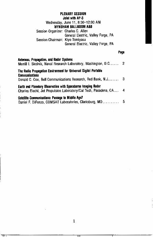
PLENARY SESSION Joint with AP-S
Wednesday, June 11, 8:30-12:00 AM WYNDHAM BALLROOM A&B
Session Organizer: Charles C. Allen General Electric, Valley Forge, PA
Session Chairman: Kiyo Tomiyasu General Electric, Valley Forge, PA
Page
Antennas, Propagation, and Radar Systems Merrill I. Skolnik, Naval Research Laboratory, Washington, D.C...... 2
The Radio Propagation Environment for Universal Digital Portable Communications Donald C. Cox, Bell Communications Research, Red Bank, N.J....... 3
Earth and Planetary Observation with Spaceborne Imaging Radar Charles Elachi, Jet Propulsion Laboratory/Cal Tech, Pasadena, CA.... 4
· Satellite Communications: Passage to Middle Age? Daniel F. DiFonzo, COMSAT Laboratories, Clarksburg, MD.......... 5
1
ANTENNAS, PROPAGATION, AND RADAR SYSTEMS
MERRILL I. SKOLNIK
Radar Division, Naval Research Laboratory
The technical areas that are included within the scope of the
Antennas and Propagation Society are of more than ordinary importance
to radar. Radar design and application requires understanding of
(1) the antenna as the co~pling between the radar and the rest of the
world, (2) the propagation of electromagnetic waves in the natural
environment, and (3) the nature of scattering from targets and
clutter. Of the many diverse radar technical subjects identified
with AP-S, scattering has probably received as much attention as
any other. Knowledge of scattering from targets and clutter is a
key element of target recognition, remote sensing of the environment,
detection of targets in clutter, and military applications.
There has been increased use in radar of the planar aperture
antenna, low sidelobe antenna, solid-state transmitters commingled
with the antenna, phased arrays, and adaptive techniques. To the
radar systems engineer "big is beautiful" when it comes to the
antenna. There has been less work in radar propagation, other than
in the prediction of propagation performance; but there are still
unsolved problems in ducted propagation and in predicting low
altitude coverage.
This talk will review several of the areas of antennas, propa
gation, and scattering that are of concern to the radar systems
engineer. It will indicate what is of current interest and what
yet needs to be done.
®1986 IEEE, Reprinted with permission from IEEE Antennas and Propagation Society Symposium Digest, Vol. II
2
THE RADIO PROPAGATION ENVIRONMENT FOR
UNIVERSAL DIGITAL PORTABLE COMMUNICATIONS
D. C. COX BELL COMMUNICATIONS RESEARCH
331 NEWMAN SPRINGS ROAD RED BANK, NJ 07701-7020
The provision of portable communications, that is, communications to people away from their wireline telephones, is a rapidly expanding communications frontier. The portable communications environment consists largely of rooms, hallways and other space within and around houses and buildings. This environment is characterized by extreme multipath propagation and severe shadowing or blocking of radio paths, both of which result from the presence of walls, ceilings and objects. Quantitative descriptions of propagation parameters such as time delay spread, attenuation, crosspolarization coupling and various signal correlations are needed to facilitate the design of an efficient and reliable Universal Digital Portable Communications System. Only in recent years have measurements of these needed propagation parameters been made. The radio propagation environment for Universal Digital Portable Communications will be illustrated using results from recent propagation measurements made within and around houses and buildings.
©1986 IEEE, Reprinted with permission from IEEE Antennas and Propagation Society Symposium Digest, Vol. II
3
EARTH AND PLANETARY OBSERVATIONS WITH SPACEBORNE IMAGING RADARS
Charles Elachi Jet Propulsion Laboratory
California Institute of Technology 4800 Oak Grove Drive Pasadena, CA 91109
The late 80's and 90's will see a major expansion in the use of spaceborne imaging radars to observe, monitor and study the Earth's surface and to map the hidden surfaces of Venus and Titan.
A series of shuttle imaging radar (SIR) experiments are planned as a joint effort between the U.S. and Germany leading to the development of multispectral multipolarization high resolution imaging systems to be used on the U.S. polar platform (Earth Observing System, EOS) planned for the mid-nineties. The SIR series will build the base for the science, techniques and technology used in radar observation of surface features, properties and phenomena.
A number of free flying orbiting imaging radars are planned by the European Space Agency (1990), Japan (1991) and Canada (1992) with the objective of observing and monitoring long term changes in the ocean features, polar ice and surface cover. These sensors will have imaging resolutions of a few tens of meters.
Similar systems, although less sophisticated, are planned to map the cloud covered surfaces of Venus and Titan. The Magellan spacecraft will orbit Venus in 1988 and carries an imaging radar with the objective of mapping 90% of the planet's surface at a resolution of better than 250 meters. In the late 90' s the Cassin! spacecraft will orbit Saturn and fly by Titan at least a dozen times. During each flyby an imaging radar will map a strip of the surface at a resolution of a few hundred meters to a few kilometers. By the end ,of the mission it would be possible to map almost the totality of this mysterious world.
®1986 IEEE, Reprinted with permission from IEEE Antennas and Propagation Society Symposium Digest, Vol. II
4

SATELLITE COMMUNICATIONS: PASSAGE TO MIDDLE AGE?
ABSTRACT
Daniel F. DiFonzo Communications Satellite Corp.
Clarksburg, Md. 20871
The commercial satellite communications industry is barely more than two decades old and is already experiencing symptoms of passage to middle age: The regulated environment of its early youth protected its market share and promoted investment in space and earth facilities designed to maximize transmission capacity for international point to point telephone traffic among a relatively few expensive earth antennas. The rapid growth and vigor of its young adult phase was encouraged by domestic deregulation and adoption of regional satellite systems by many countries. Because of the bandwidth limitations of terrestrial media, satellites proved cost-effective for high capacity requirements, especially TV distribution.
The middle age symptoms of slowing down of growth and awareness of mortality are precipitated by the advent of fiber optics networks and the implications of further deregulation. Now there is much introspection about the competitive position of satellite communications with some arguing that this medium will hardly be used at all for voice traffic and will even suffer in respect to video and data applications unless end to end costs can be reduced. Are satellites then relegated to niche markets such as land mobile, thin route, and point to multipoint? Is this such a bad thing?
This talk will describe these "passages" and the role of advanced network architectures and antenna developments in improving this medium's competitive position to secure its graceful transition to old age.
®1986 IEEE, Reprinted with permission from IEEE Antennas and Propagation Society Symposium Digest, Vol. II
5

6

PHILA. SOUTH A-1 MEASUREMENTS
Joint with AP-S Chairman: G. Smith/ A. Repjar
MONDAY-AM Page
8:30 CHAIRMAN'S REMARKS 8:40 Dielectric Spectroscopy Using Monopole Antennas of
General Electrical Length W.R. Scott, Jr. and G.S. Smith, Georgia Institute of Technology. . . . . . . . . . . . . . . . . . . . . . . . . . . . . . . . . . . . . . . . . . . AP Digest
9:00 Reflection and Transmission Measurements of Advanced Composite Materials Jefferson F. Lindsey Ill, Southern Illinois University at Carbondale ......................................... AP Digest
9:20 A Closed Form Solution for Anisotropic Magnetic Material Properties Measurement-Part 1. Theoretical Formulation H.H. Chuhg, G.A. Pfaff, and S.Y. Peng, Teledyne Ryan Electronics.................................... 8
9:40 A Closed Form Solution for Anisotropic Magnetic Material Properties Measurement-Part II. Experimental Investigation G.A. Pfaff, H.H. Chung and S.Y. Peng, Teledyne Ryan Electronics.................................... 9
10:00 COFFEE BREAK 10:20 Evaluation of Antenna Measurement Techniques for Satellite
Communications and Radar Systems Andrew G. Repjar, National Bureau of Standards. . . . . . . . . . . . . . . 1 O
10:40 Improved Time Domain Gating Technique for Antenna Measurements R. Balaberda and S.R. Mishra, National Research Council of Canada ............................................ 11
11 :00 Reflector Antenna· Surface Profile Tolerance Measurement by Ultrasound or Microwave Remote-Sensing C.G. Parini, A.K.K. Lau, and P.J.B. Clarricoats, University of London .................................. AP Digest
11 :20 A New Scattering Matrix Measurement Technique Using Six-Port Concept and a Sliding Short L. Kaliouby and R.G. Bosisio, Ecole Polytechnique of Montreal. . . . . . . . . . . . . . . . . . . . . . . . . . . . . . . . . . . . . . . . . . . . . . . . . . 12
7

A CLOSED FORM SOLUTION FOR ANISOIROPIC MAGNE'l'IC MATERIAL PROPERTIES MEASUREMENI'
PART I. THEDREI'ICAL FORMUIATION
H. H. Chung, G. A. Pfaff and S. Y. Peng TELEDYNE RYAN ELEX::TRONICS
8650 Balboa Ave. San Diego, CA 92123
By using a multiple position cavity method, a closed form solution was obtained for practical application in computing both complex permeability (jJ} and complex permittivity (E) of an anisotropic magnetic material. The computation was based on the measured resonant frequency and quality factor (Q) parameters. The pertubation technique and proper boundary conditions were applied in the derivation of the required formulas. An analytical model for a TEOll rectangular waveguide cavity was developed and a set of equations were derived that relate both {;J) and (E) to the change in resonant frequency and unloaded (Q) caused by the insertion of a thin material sample into the cavity. A computer model was generated using the derived equations. A set of final equations and computing procedure has been established for practical applications.
The computer model has been used to identify the properties of unknown Radar Absorption Material (RAM) and known dielectric material. The computed results based on the measured data of resonant frequency and Q parameters for known dielectric material agree well with the published reference data. For the unknown anisotropic magnetic material, the computed results show promising progress made in the development of the RAM. An extensive laboratory investigation was conducted to verify the theoretical model. The detail of the experimental investigation results will be presented in a separate paper. In this paper, the detail derivation will be presented, and application of the formulas obtained wil 1 be discussed.
8

A CLOSED FORM SOLlJrION FOR ANISOI'ROPIC MAGNEI'IC MATERIAL PROPERTIES MEASl.JREMENI'
PART II EXPERIMENI'AL INVFSTIGATICN
G. A. Pfaff, H. H. Chung, and S. Y. Peng 8650 Balboa Ave.
San Diego, CA 92123
To implement the multiple position cavity test method based upon the analytic solution discussed in Part I, an X-band waveguide cavity test fixture was designed and fabricated. A carefully calibrated network analyzer system is used for measuring the complex input impedance of the cavity as a function of frequency. Input impedance was recorded on a specially prepared Smith Chart Data Sheet and frequencies for the resonant frequency and half-power points were carefully measured and recorded.
An extensive laboratory measurement program was conducted to insure data quality. An important consideration in developing the cavity test method was the question of how to accurately position and hold the test samples in the test fixture cavity without introducing a source of error that could not be accounted for. It was decided to use a low density foam material to position and hold the samples in place while making the cavity measurements.
Based upon the samples provided by Aberdeen Proving Ground, a test procedure was developed to measure the resonant frequency and unloaded quality factor (Q) of the cavity for each of the required sample test positions. Three positions are required to determine an aniso:tropic magnetic material properties. Six positions were selected for this test program. This provided redundant data for cross checking the final test results. A set of known dielectric material was also tested, to provide baseline data for comparison with published values of dielectric constant. The detail test equipment setup, test procedures and the measured results will be preserited.
9

EVALUATION OF ANTENNA MEASUREMENT TECHNIQUES FOR SATELLITE COMMUNICATIONS AND RADAR SYSTEMS
Andrew G. Repjar, Electromagnetic fields Division, National Bureau of Standards, 325 Broadway Boulder, Colorado 80303
Near-field techniques, far-field techniques, compact ranges, spherical arch methods, and anechoic chambers are among the options presented when one must choose a measurement system which has the capability to fulfill antenna or radar cross section measurement needs. Each of these methods must be evaluated to determine how well they meet the measurement requirements. Often one measurement system may offer clear advantages in certain areas, but may fall short in another area which is considered critical, and the choice becomes difficult.
To aid in this decision, a three-step evaluation process has been developed which compares the relative merits of the various measurement approaches as they apply to connnunication satellite, radar, and other antennas. The first step in the process is a clear description of the antenna system to be measured and the identification of the evaluations factors which are determined by the antenna, e.g. size of the test zone, the susceptibility of the antenna to adverse environments, etc. The second step is a description of essential features of the measurement technique under consideration and a definition of the measurement system evaluation factors, e.g. measurement time, practicality to implement, etc. The third step is to assign relative weights to the factors to indicate their relative importance for the particular application being studied. Weighted sums of the evaluation factors are then computed to rate each measurement method.
Using the above process. the details and the· assumptions leading to a decision are clearly presented. If there are questions about the final decision, these details and assumptions can be reviewed to verify a correct statement of the problem and justifiable rating of each alternative.
Through this presentation, it is intended that areas of interest and concern, relating to the various measurement techniques be brought to the forefront.
10

IMPROVED TIME DOMAIN GATING TECHNIQUE FOR ANTENNA MEASUREMENTS
R. Balaberda S.R. Mishra National Research Council of Canada
Ottawa, Ontario, Canada KOA ORS
The use of time domain gatings, to reduce multipath reflec
tions errors, has recently become a practical antenna measurement
technique because of the recent advances in computing and instru
mentation technology. In this technique, measurements are made in
the frequency domain, the data is transformed to the time domain,
unwanted time components are removed (time gating), and then this
gated data is transformed back to the frequency domain. The time
gated frequency domain data is then due only to the antenna system
free of multipath responses.
A problem with this technique is that the time domain direct
and multipath response are stretched out. This stretching
(dispersion) is due to the frequency response of the antenna
network. Dispersion reduces the shortest path length differences
that can be resolved and gated.
The time gating techniques' accuracy can be increased by
removing the antenna network's frequency response before gating,
and then re-establishing the antenna network's frequency response
on the gated data. The frequency response of the antenna network
can be either computed or measured.
Details of this dispersion suppressed time gating technique,
its applicability to antenna measurements,and some measured data
will be presented.
11

A NEW SCATTERING MATRIX MEASUREMENT
TECHNIQUE USING SIX-PORT CONCEPT AND
A SLIDING SHORT
L. Kaliouby, R.G. Bosisio
Ecole Polytechnique of Montreal
Montreal, Quebec, Canada
The measurement of reflection coefficient at microwave frequencies has recently been mede possible by using six-port technique, that is, by meens of power readings only, eliminating thus the need for heterodyne technique.
The use of six-port becomes then a very attractive technique for the measurement of the scattering matrix of a symmetrical two-port device. In fact, it is known that to evaluate S11, S12= S21 and S22, it's only sufficient to measurer when the device under test is succressively backed by three different loads, such as a matched load, an open circuit and a short circuit.
However, for a set of measurement that have to be done in real-time or swept frequency mode, the frequent connection and deconnection of loads tond to reduce the repP.tability and precision of results.
In this paper, a new measurement technique of the scattering matrix, based on the use of a sliding short is developped. It is shown that by plotting the locus of r when the position of the sliding short is changed, it's possible by simple graphical means, to deduce most of the relevent infonnation.
12

WYNDHAM D A-2-NEARFIELD MEASUREMENT
Joint with AP-S Chairman: E.S. Gillespie
MONDAY-PM Page
1 :30 CHAIRMAN'S REMARKS 1 :40 Differential Sampling of Planar Near-Fields
L.E. Corey and D.R. O'Neil, Georgia Tech Research Institute ..................................... AP Digest
2:00 The Effect of Random Errors in Planar Near-Field Measurements Allen C. Newell and Carl F. Stubenrauch, National Bureau of Standards .................................. AP Digest
2:20 Measurement of Array Element Excitations Using a Planar Near-Field Range K. N. Sherman, Hughes Aircraft Company.. . . . . . . . . . . . . . AP Digest
2:40 The Results and Estimates of Uncertainties from Planar NearField Measurements on Very Low Sidelobe Antennas A.G. Newell and M.H. Francis, National Bureau of Standards; K. Grimm and J. Hoffman, Technology Service Corp ................................................. 14
3:00 COFFEE BREAK 3:20 On the Modulated Scattering Technique for Rapid Near-Field
Measurements B.J. Cown, Georgia Tech; J. Ch. Bolomey, LSS, Groupe D'Electromagnetisme. . . . . . . . . . . . . . . . . . . . . . . . . . . . . . . . . . 15
4:00 Computer Simulation of Near-Field/Far-Field Scatteri11g W.H. Hallidy, W.T. Moore and I.J. LaHaie, Environmental Research Institute of Michigan.... . . . . . . . . . . . . . . . . . . . . . . . . . . . . 16
13
THE RESULTS AND ESTIMATES OF UNCERTAINTIES FROM PLANAR NEAR-FIELD MEASUREMENTS ON VERY LOW SIDELOBE ANTENNAS
A.C. Newell, M.H. Francis Electromagnetic Fields Division National Bureau of Standards Boulder, CO 80303
K. Grimm, J. Hoffman Technology Service Corp. Washington Division Silver Spring, MD 20910
An extensive measurement program has recently been completed in which two antennas were tested using the planar near-field technique. From the known design parameters and from previous far-field measurements, both of these antennas were known to have very low sidelobe levels over large angular regions. They were therefore used as test articles to evaluate the accuracy of the near-field technique and to try some new concepts in an attempt to reduce the effect of some sources of error.
Two probes were used in these tests. The first was an open-ended waveguide which has been standard in many near-field measurements. The second was composed of two open-ended waveguides whose outputs were combined in a 180° hybrid. By proper choice of the cable lengths between the two waveguides, a deep null in a direction coincident with the main beam of the test antenna could be produced in the probes receiving pattern. Using the near-field theory, and previous error analyses, one can predict that this type of probe should be less sensitive to some near-field errors. Some of the tests were oriented towards verifying these predictions and determining if the probe had limitations.
In order to quantify the total uncertainty in the measurements for both the DEW and difference probe, a four step process was used. First, known systematic errors from individual sources were introduced in the measurements one at a time, and the results compared with measurements without the introduction of errors. These tests, along with mathematical analysis verified that previously derived error equations were valid for the very low sidelobe antennas and the special probe. Secondly, the magnitude and in some cases the specific character of the error functions were determined for the measurement system. For instance the Z-position error function ~Z{X,Y) was determined using laser optical systems. In the third step the error equations and the nearfield error magnitudes were combined to predict the effect on the farfield results. In the final step, all of the error sources were combined to give a resultant estimate of error.
The major conclusions were that previously derived error equations and error diagnostic tests are valid for the very low sidelobes antennas; the difference probe does reduce the effect of most systematic and random error sources; multiple reflections between the test antenna and the probe was the largest error source; and total estimated uncertainty for sidelobe levels of -50 to -60 dB was on the order of 5 to 10 dB.
14
ON THE MODULATED SCATTERING TECHNIQUE FOR RAPID NEAR-FIELD MEASUREMENTS
B. J. Cown EMED/ECSL/GTRI
Georgia Institute of Technology Atlanta, Georgia 30332, USA
J. Ch. Bolomey LSS, Groupe D'Electromagnetisme
Plateau Du Moulon 91190 Gif-Sur-Yvette, France
The modulated scattering technique (MST) [J.H. Richmond, IRE Trans., 1955b, MTT-3, (4)] employs hundreds of electrically-small probes modulated at audio frequencies to rapidly measure the electric field distribution, both amplitude and phase, over a near-field (NF) measurement surface in a few seconds or minutes, depending on whether 2-D or 1-D arrays of modulated scattering elements are employed. Results of recent· collaborative research work conducted jointly by the Groupe d'Electromagnetisme (GEM) and by the Electromagnetic Effectiveness Division (EMED) strongly indicate that MST-based NF measurement systems can provide efficient, accurate and cost-effective engineering solutions for a large variety of near-field measurement applications. The MST is particularly attractive for applications involving spacecraft or space-borne antennas; phased array antennas, collection of inverse scattering/microwave imaging data, and for development of portable NF test facilities.
Experimental pattern data obtained via 1st and 2nd generation MST prototype NF measurement systems at GEM and EMED will be compared with classical (mechanically-scanned waveguide probe) NF pattern data for horn antennas and reflector antennas. Factors affecting the speed and accuracy of MST-based NF measurements - dynamic range, interactions of test antennas and MST array, mutual coupling of MST array elements, etc. - will be further discussed and illustrated via results of numerical data simulations, The relative advantages and limitations of the MST will be delineated and discussed with respect to the classical NF technique [J. Ch. Bolomey, Ann. de Telecomm., tome 40, Jan - Feb 1985; B.J. Cown, Final Technical Report, Army contract DAAB07-85-K-KSIS, Feb., 1986] •
15

COMPUTER SIMULATION OF NEAR-FIELD/FAR-FIELD SCATTERING
William H. Hallidy, William T. Moore and Ivan J. LaHaie Environmental Research Institute of Michigan
P.O. Box 8618 Ann Arbor, MI 48107-8618
One method of determining the radiation pattern of antennas that has become widely adopted is that of measuring the field on a plane a few wavelengths from the antenna then appropriately weighting the Fourier transform of these measurements to obtain the far field pattern. A theory applying this near-field/far-field transformation method to the scattering problem, where both the transmitter and receiver are in the near-field of the scatterer, has recently been developed (M.A. Dinallo. Proc. AMTA. Oct. 2-4,1984, San Diego, CA) as an extension of the well known plane-wave scattering-matrix (PWSM) theory applied to antennas (D.M.Kerns. NBS Monograph 162, USGPO, Wash .• 1981).
A two dimensional computer sirrulation based on Dinallo's theory has been developed by the authors to study numerical convergence of the transform. Scattering by a cylinder has been modeled for both the TEz and TMz case using eigenfunction expansions for source and receiver positions along a line located a finite distance from the cylinder. A discrete Fourier transform was applied to ascertain the far field radar cross section (RCS), which was subsequently compared with the RCS obtained from the eigenfunction expansion for asymptotically disposed source and receiver locations. The source and receiver are considered to be ideal in this sirrulation.
In contrast to antennas, which normally do not radiate significant amounts of energy at wide angles to boresight. nearly all targets scatter significantly at large angles to the illumination direction. This wide angle scattering manifests itself as numerical instabilities in the Fourier transform of the sampled field at the highest spatial frequencies. These, in turn, cause a ringing problem in the transformed field that was removed by modifying the measurement window. Resulting plots of the RCS are found to agree to within 0.5 dB for source and receiver lying within a 120 degree sector centered on a line perpendicular to the measurement line.
16

WYNDHAM C A-3-EM SCATTERING MEASUREMENTS
Chairman: W.J. English TUESDAY-PM
1 :30 CHAIRMAN'S REMARKS 1 :40 An Analysis of Compact Range Measurements
P.H. Pathak and R.G. Kouyoumjian, Ohio State University; A. Nagamune, Nippon Kokan K.K. Technical Research
Page
Center, Kawasaki, Japan ..................................... 18 2:00 High Range Resolution Techniques for Broadband Coherent Radar
E.K. Walton, Ohio State University ............................ 19 2:20 Transient Polarization Signatures of Electromagnetic Scatterers
N.F. Chamberlain, E.K. Walton and F.D. Garber, Ohio State University..... . . . . . . . . . . . . . . . . . . . . . . . . . . . . . . . . . . . 20
2:40 Measured Impulse Response Polarization Matrix for Off-Axis Angles on a Square Plate J.D. Young and P. Reed, Ohio State University ................. 21
3:00 COFFEE BREAK 3:20 Experimental Determination of the Scattering Matrix for Rain in the
X and Q Bands D.W. Carnegie, A.P. Agrawal and W.M. Boerner, University of Illinois .......................................... 22
3:40 Polarimetric Radar Signal Optimization in the Partially Polarized Case for Target Detection in Clutter A.B. Kostinski and W.M. Boerner, University of Illinois .......... 23
4:00 Assessment of Polarimetric Millimeter Wave Sensors in the Design of Airborne/Marine Ground Vehicle Collision Avoidance and Traffic Flow Control Radars M. Walther and W.M. Boerner, University of Illinois ............. 24
17
AN ANALYSIS OF COMPACT RANGE MEASUREMENTS
P.H. Pathak , R. G. Kouyoumjian The Ohio State University ElectroScience Laboratory
Department of Electrical Engineering Columbus, Ohio 43212
A. Nagamune Nippon Kokan K.K., Technical reeearch Center
Kawasaki-Ku, Kawasaki 210, Japan
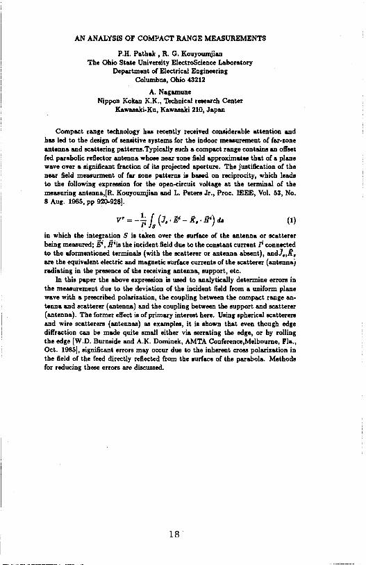
Compact range technology hu recently received conaiderable attention and hu led to the design of senaitive systems for the indoor measurement of far-zone antenna and scattering patterna.Typically such a compact range contains an offset fed parabolic reflector antenna whoee near zone field approximates that of a plane wave over a significant fraction of its projected aperture. The justification of the near field meuurment of far zone patterns is baaed on reciprocity, which leads to the following expression for the open-circuit voltage at the terminal of the measuring antenna,[R. Kouyoumjian and L. Peters Jr., Proc. IEEE, Vol. 53, No. 8 Aug. 1965, pp 920-928!.
V' = -~ l (J,. If - K, • .ir) da (1)
in which the integration S is taken over the surface of the antenna or scatterer being measured; l;i, .fliis the incident field due to the conatant current Ji connected to the aformentioned terminals (with the scatterer or antenna absent), andJ,,K, are the equivalent electric and magnetic surface currents of the scatterer (antennaj radiating in the preeence of the receiving antenna, support, etc.
In this paper the above expression is used to analytically determine errors in the measurement due to the deviation of the incident field from a uniform plane wave with a prescribed polarization, the coupling between the compact range antenna and scatterer (antenna) and the coupling between the support and scatterer (antenna). The former effect is of primary interest here. Using spherical scatterers and wire scatterers (antennas) u examples, it is shown that even though edge diffraction can be made quite small either via serrating the edge, or by rolling the edge [W.D. Burnaide and A.K. Dominek, AMTA Conference,Melbourne, Fla., Oct. 1985!, significant errors may occur due to the inherent cr088 polarization in the field of the feed directly reflected from the surface of the parabola. Methods for reducing these errors are discussed.
18
HIGH RANGE RESOLUTION TECHNIQUES FOR BROAD BAND COHERENT RADAR
Eri C K. Wal ton The Ohio State University ElectroScience Lab.
1320 Kinnear Road, Columbus, CH 43212
The process of transforming wide band coherent radar scattering data to the time domain is important in the study of the various mechanisms inherent in scattering from a complex radar target. This paper describes a technique for the time domain transformation which concentrates on the task of finding the time of arrival of a particular signal component to a high precision. This technique works best if the particular scattering modes of interest approximate an impulsive function in the time domain over the bandwidth utilized.
If a radar target is considered to be a collection of scattering centers, each of which is small with respect to a wavelength. it can be seen that the quantities measured as a function of frequency with a coherent radar system Cthe I and Q components> are made up of a set of sinusoids where the period is related to the distance of the associated scatterer from the phase reference zero plane. A Fourier transform of I Cf) or Q(f) will recover the distribution of amplitude versus time (and also distance).
This paper discusses a technique for the high resolution location of such scattering centers. In this technique, a Gaussian window is first applied to the I(f) or Q(f) data, and then a Fourier transform is used to transform to the time/distance domain. The result is that the responses in the time domain are Gaussian (even if the original data were noisy). In the case where the responses are not overlapping, it can be seen that the center of each such Gaussian represents the location of the associated scattering center.
This paper will show that it is possible to achieve much higher resolution than the classical inverse of the observation bandwidth Cin this non-overlapping case). This can be done by fitting a Gaussian to the time/distance domain data.
The limitation of the technique will be discussed, examples will be given, and comparisons with SEM/autoregressive techniques will be discussed.
19
TRANSIENT POLARIZATION SIGNATURES OF ELECTROMAGNETIC SCATTERERS
N. F. Chamberlain, E. K. Walton, F. D. Garber
The Ohio State University ElectroScience Laboratory
Electrical Engineering Department Columbus, Ohio
The polarization state of an electromagnetic wave can be represented by two orthogonal vectors, e.g. horizontal and vertical are commonly used. Plotting the instantaneous locus of the electric field vector yields the familiar ellipse (in general), or circles, straight lines etc. Although we refer to this depiction as being 'instantaneous', which indeed it is, the plot usually represents only one frequency.
If backscatter data from a conducting object are available over a band of frequencies, the data can be transformed into the time domain to obtain the band limited impulse response of the object. The result is a time history of the scattering process as a plane wave washes over the object. If we display the received vertical component versus the received horizontal component as a function of time, for the case of circular illumination, we have in effect, a time domain polarization plot.
This paper discusses some recent findings when a variety of perfectly conducting objects are subject to illumination by impulsive plane electromagnetic waves having (synthesized) circular polarization. Our data were measured in the 1-12 Ghz band using the compact range at the ElectroScience Laboratory. The purpose of this study is to gain insight into the manner in which the various physical features of an object influence the polarimetric behavior of its backscatter, and to evaluate the potential of the application of these signatures to identification of the object.
20
MEASURED IMPULSE RESPONSE POLARIZATION MATRIX FOR OFF-AXIS ANGLES ON A SQUARE PLATE
Jonathan D. Young Paul Reed
The Ohio State University ElectroScience Laboratory Department of Electrical Engineering
Columbus, Ohio 43212
The impulse response waveforms were measured for all polarizations and several off-axis look angles on a flat 30cm square plate. The frequency spectrum of the data spans the region .6 <kl< 100, where Lis the length of the plate edge. The system used was the OSU compact range, with pulsed stepped cw frequency-domain transfer function measurement, vector background subtraction, and calibration with a 15 cm conducting sphere.
The impulse waveforms to be presented show that there are a relatively small number of scattering centers, each with an identifiable time-domain shape and polarization response. The properties of these features vs target geometry will be discussed.
21
EXPERDm'ffAL DETEBMINATI~ OF THE SCAT'l'ERIH3 MTRIX FOR BAIN IN THE X- AND Q-IWmS
David w. Carnegie, Amit P. Agrawal and Wolfgang-M. Boerner ColllllUilications Laboratory, SEL-4210
Department of Electrical Engineering & Computer Science (nVc 154) University of Illinois at Chicago
Chicago, IL 60680-4348
ABSTBACr
This paper presents an evaluation of an experimental program done to measure the full scattering matrix for rain as a function of the weather conditions under a contract to the Army Missile Conunand (MI-coM/AMSI-REG-POL, STAS 1597, Contract No. DAAG29-81-D-0100). The data consists of fifty files representing varying weather conditions. Each data file consist of rain cell scattering matrix data given as a discrete time sequence in the X- and Q-bands (8.9 GHz and 45 GHz, respectively). The X-band data consists of 2048 points spaced 400 micro-sec. for a total elapsed time of about 0.8 sec. The Q-Band consists of 32 points spaced 400 micro-sec. so that they span a time of about 13 µsec. The scattering takes place in a "rain cell" defined by the beam widths and down range distances 275 ft. through 325 ft.
Our initial analysis of these data sets concentrated on calculations of autocorrelation and autocovariance functions for the matrix elements. Considerable structure is apparent in the resulting plots, notably a periodic fluctuation imposed on a decaying function. This structure corresponds to an observed periodic fluctuation in the magnitudes of the elements of the scattering matrix. From the plots of the autocorrelation function we may determine the "decorrelation time" for rain as a function of the weather conditions. Additional results from the analysis of the magnitudes and relative phases of the scattering matrix coefficients, co-pol and x-pol null polarizations, differential reflectivity (Z0R), and circular depolarization ratio (CDR) were determined and are interpreted.
our analyses demonstrate the usefulness of polarization measurements and point out the need for continued experimental work and expansion of this applied polarimetric research.
22
POLARIMETRIC RAIWt SIGNM. OPTIMIZATICR IN THE PARTIALLY POLARIZm CASE FOR TARGET DETECTICR IN CLUTTER
Alexander B. Kostinski and Wolfgang-M. Boerner Communications Laboratory, SEL-4210
Department of Electrical Engineering & Computer Science (111/c 154) University of Illinois at Chicago
Chicago, IL 60680-4348
ABS'DU\CT
The procedure for finding optimal polarizations is proposed for the case of partially polarized waves reflected off non-stationary radar targets. It is based on Kennaugh's characteristic target operator theory and our recent "three stage" extension of it.
We assume that complete coherency matrix information (or equivalently, Stokes vector) is available from radar measurements. Based on this information a unigui decomposition is performed into a completely polarized and a comp etely unpolarized part. Only the completely polarized part of the reflected signal is then used to define a target scattering operator. The problem of optimizing the voltage at the receiving antenna terminals then reduces to the completely polarized case optimization, i.e., Kennaugh's optimal polarization theory. we have generalized that theory to a nonreciprocal and bistatic case by employing the three-stage procedure which involves solving an eigenvalue problem for the Graves power matrix and then adjusting the receiver polarization via the voltage match condition. (For a more detailed discussion see a companion AP-S paper. ) Various time-scale limits of coherency-matrix decomposition are analyzed in detail.
Such a procedure can also be used for an improved detection of fluctuating and distributed targets.
23
ASSESSMl!Nl' OF POLARIMETRIC MILLDIETER WAVE SffiSORS IN '!BE DESIW OF AIRBQRNE/MI\RINE GROOND VEHICLE CDLLISI<»f AVOIDI\NCE
AND TRAFFIC FLOf CDfmOL RADARS
Matthias Walther and Wolfgang-M. Boerner CollD'llllllications Laboratory, SEL-4210
Department of Electrical Engineering & Computer Science (nVc 154) University of Illinois at Chicago
Chicago, IL 60680-4348
ABSTRACT
Recent advances in integrated circuit technology applied to millimeter wave technology has resulted in the design of small and portable radar devices capable of detecting targets within a closed range (several meters) and up to several kilometers. Of special interest is the FM/CW radar mode of operation, providing very good resolution for small targets under adverse weather conditions (rain, fog, snow, dust) when optical/laser sensors fail in their operation.
Not just the military, but also the civil sector is being introduced to a whole new array of advanced and less expensive radar devices and it is one of the first objectives to critically assess developments of millimeter wave devices already in use in medical radiometry, chemical and industrial measurement/process control, automatic airborne/marine/land vehicle collision avoidance, atmospheric sounding, etc.
A critical review of existing technology in R&D efforts within EC/JapanjKorea;'l'aiwan and US/Canada is provided. In particular, non-cooperative stand-alone automotive collision avoidance and integrated traffic flow control radars are analyzed and various approaches are critically assessed. In our evaluation we found that, although FM/CW radar systems have been highly advanced, great need exists in improving methods of interference suppression from roadside/atmospheric backscatter. Most recently, several polarimetric millimeter wave radar principles are being considered and investigated, including beam sharpening and polarization diversity switching for backscatter interference reduction and transfers traffic flow monitoring.
24
WYNDHAM C B-1-ANTENNAS
Chairman: B.D. Steinberg MONDAY-AM
Page
8:30 CHAIRMAN'S REMARKS 8:40 A Simple Leaky Wave Antenna that Permits Flexibility in
Beam Width A.A. Oliner, Polytechnic Institute of New York; P. Lampariello, University of Rome, Italy. . . . . . . . . . . . . . . . . . . . . . 26
9:00 Coupling Effects in an NRD Guide Leaky Wave Antenna H. Shigesawa and M. Tsuji, Doshisha University; A.A. Oliner, Polytechnic Institute of New York ................. 27
9:20 Finite Length Helical Sheath Antenna in a General Homogeneous Medium J.P. Casey, Naval Underwater Systems Center; R. Bansal, University of Connecticut. ......................... 28
9:40 Phase Centre Considerations for the Log-Spiral Antenna J.M. Tranquilla and S.R. Best, University of New Brunswick ..... 29
10:00 COFFEE BREAK 10:20 C-Band Rigid Helical Antenna
A. Kumar, Spar Aerospace Limited ............................ 30 10:40 Bandwidth Optimization for Specified Antenna Gain Patterns
R. M. Bevensee, Lawrence Livermore National Laboratory. . . . . . . 31 11 :00 Design Consideration for SATCOM Terminal MMIC Antenna on
Advanced Aircraft C.J. Chen, TRW ............................................. 32
11 :20 Dielectrically Loaded Wire Antennas J.P. Casey, Naval Underwater Systems Center; R. Bansal, University of Connecticut. ......................... 33
25

A SIMPLE LEAKY WAVE ANTENNA THAT PERMITS FLEXIBILITY IN BEAM WIDTH
A. A. Oliner Polytechnic Institute of New York
Brooklyn, New York, USA
and
P. Lampariello University of Rome "La Sapienza"
Rome, Italy
Last year we described a new leaky wave antenna based on groove guide that was particularly simple in form ("A New Simple Leaky Wave Antenna for Millimeter Waves," URSI Symposium Digest, p. 57, Vancouver, Canada, June 17-21, 1985). The antenna possessed many merits but it had one disadvantage; it leaked strongly under most conditions, so that it readily yielded wide beams, but narrow beams were achieved only for restricted dimensional ranges. We now present a modification of that structure that permits great flexibility in the range of desired beam widths.
The structure discussed last year consisted of groove guide bisected longitudinally with a metal wall along the long axis of its cross section. The cross section then looks like a length of parallel plate guide with a short tee stub at its center but on one side only. An accurate analysis of the phase and leakage properties was conducted by deriving an equivalent circuit for the tee stub configuration and then employing it in a transverse resonance procedure.
By symmetry, that structure can also be bisected along the narrow axis of groove guide, producing as a result an open waveguide with an L-shaped cross section, where one end (say, the horizontal one) is closed and the other end (the vertical one) is open, permitting the leakage of radiation. The performance characteristics are not affected by this second bisection. In the modified structure, for which results are presented here, the vertical portion of the L, which may be regarded as an open stub, is moved from its end position to some position nearer to the center. In the exact central position, the structure resembles groove guide bisected horizontally, and no radiation is produced. At the other extreme, with this open stub at one end, we have the antenna discussed last year, which leaked very strongly. The leakage rate can therefore be controlled by locating the open stub at intermediate positions.
This modified structure has been analyzed in accurate fashion, and numerical results are presented which illustrate the flexibility in beam widths obtainable because of the new degree of freedom described above.
26

COUPLING EFFECTS IN AN NRD GUIDE LEAKY WAVE ANTENNA
H. Shigesawa and M. Tsuji Doshisha University
Kyoto 602, Japan
and
A. A. Oliner Polytechnic Institute of New York
Brooklyn, New York 11201
Nonradiative dielectric (NRD) guide, a waveguide suitable for millimeter-wave integrated circuits, consists of a dielectric strip placed between parallel metal plates with the electric field oriented parallel to the plates. The basic mode is purely bound, and all discontinuities are purely reactive when the plate separation is less than X
0/2,
It was shown (A. A, Oliner, S. T. Peng and K. M. Sheng, "Leakage from a Gap in NRD Guide," IEEE International Microwave Symposium Digest, pp. 619-622, June 1985) that an air gap introduced between the dielectric strip and one of the plates produces asymmetry that converts some of the field to a TEM mode that leaks away at an angle from the region of the strip. When the plates are made finite in width, the structure with an air gap becomes a leaky wave antenna.
The performance of this class of antennas was analyzed by means of a rigorously phrased mode-matching procedure, and the variation of the phase and leakage constants was obtained as a function of the dimensional parameters and the frequency, For small values of leakage, corresponding to radiated beams with beam widths of only a few degrees, the behavior was basically what we expected, with the antenna capable of simple and straightforward design.
For larger leakage values, however, some very odd and unexpected results were found. On closer examination, we noted that the finite width of the plates creates another type of leaky mode that resembles the channel guide mode associated with rectangular waveguide possessing an open side. That new mode can couple with the basic leaky mode over a wide range of parameter values, with the result that the antenna performance is seriously affected. We present not only the coupling effects but some design considerations with regard to how to overcome them or work with them.
27

FINITE LENGTH HELICAL SHEATH ANTENNA IN A GENERAL HOMOGENEOUS MEDIUM
John P. Casey Naval Underwater Systems Center, New London, CT 06320
and Raj eev Bansa 1
Department of Electrical Engineering and Computer Science The University of Connecticut, Storrs, CT 06268
The sheath helix is an anisotropically conducting cylindrical tube that represents a good approximation to an actual helix consisting of many turns per wavelength. The problem of an infinite length helical sheath antenna in free space was studied by Chen (Radio Science, 1, 589-600, 1966) to determine the asymptotic behavior of the current and the radiation pattern. In this paper, an integral equation for the current distribution along a finite length, axisymmetrically-driven helical sheath antenna in a general homogeneous medium is derived. This "Pocklington type" integral equation is based on an applied electric field source along the helical direction. The equation is solved by the method of moments to obtain the current distribution and radiation pattern of the antenna. The characteristics of various helical sheath antennas in both dissipative and nondissipative media are presented and compared with multifilar helices.
28

PHASE CENTRE CONSIDERATIONS FOR THE LOG-SPIRAL ANTENNA
SUMMARY
J.M. TRANQUILLA ANDS. R. BEST DEPARTMENT OF ELECTRICAL ENGINEERING
UNIVERSITY OF NEW BRUNSWICK FREDERICTON, N. B. CANADA
Many modem electronic distance measurement applications require postloning acct.racy of the order of the dimensions of the system antenna. One of the most rnportant such applications is the Global Positioning System (GPS) which uses a networ1< of satellites to provide earth based users with postloning intonnation. One of the significant error sources in this system is the angle-dependent phase centre displacement or the receiving antenna. One of the corrrnon antenna types used in GPS is the short logarithmic-spi"al antenna which produces the necessary en<rre circularly-polariZed pattern.
The log-spi"al antenna is analySed using the Method of Moments to oblain the radiated field amplitude and phase characteristics. The phase centre, which is defined ror a transmitting antenna as the apparent source of radiation, is calculated as a runction or polar observation angle by finding the apparent centre of clJVature of the radiated equlphase contour. For an antenna of finite extent, the shape of the equiphase contour departs from that of a uniform sphere and the phase centre will become displaced from the antenna as a function of observation angle. The phase centre displacement is calculated based on a rormulation by carrel (1961 ), that calculates the the phase centre evoh.te, which is the locus of the phase centre position as a runction of observation angle, where the only constraint is that the evolute is syrrmelrical about the antenna array line.
The suitability of the short log-spi"al antenna for GPS applications is discussed and both theoretical and measured antenna characteristics are presented.
29
C-BAND RIGID HELICAL ANTENNA
A. Kumar Antenna Engineering
Spar Aerospace Limited 21025 Trans-Canada Highway
Ste-Anne-de-Bellevue Quebec
Canada H9X 3R2
The helical antenna is of increasing interest in the satellite communication where the limited space is available. It is also important to increase the rigidity of the antenna without using a thick wall dielectric cylinder. The helical antennas have been studied by many authors for various applications.
The purpose of this paper is to describe the design, development and testing of a small ground plane helical antenna for satellite application in the frequency range 5.925 - 6.~25 GHz. The matching of the antenna has also been improved using metal strips at the feed point.
The diameter of the helix and the diameter of the ground plane were 0.0160 m. The helical antenna was placed inside a Kynar tube and it was rotated in front of a heating element for a few minutes at 3500c. The Kynar tube shrunk and formed a zig-zag layer on the helical wire and provided a rigid support to the antenna. The thickness and the relative permittivity were 0.0003 m and 2.10, respectively.
It was necessary to improve input matching by increasing the conductor size near the ground plane to reduce the helix impedance from 1~0 n to 50 n. Two metal strips were placed on the first turn of the helix. The return loss was then better than -2~ dB for both antennas in the frequency range 5.925 to 6.~25 GHz. Symmetrical radiation patterns were found of the helical antennas with and without Kynar tubing.
30
BANDWIDTH OPTIMIZATION FOR SPECIFIED ANTENNA GAIN PATTERNS*
R, M. Bevensee Lawrence Livermore National Laboratory, Livermore, CA 94550
An expression for the two-sided fractional bandwidth B (~ 100%) of a lossless metal antenna in free space has been derived, in terms of a rigorously defined time-average "reactive stored energy" WR at center frequency w0 (R. M, Bevensee, Proc. ISAP '85 Japan, II,_ 389-392, 1985), This energy is computed as a double integral of the current distribution within the antenna working volume, without employing any spherical wave expansion outside the volume. The currents also determine antenna gain ~and time-average radiated power Pav• hence the bandwidth B = Pavl(w0 WR).
That thin-wire dipole distribution which maximizes both the unidirectional gain G0 and B has already been computed for a spherical working volume of radius a/A= 2n. In this paper various highly directive patterns G(6,$) are specified for an antenna working volume of fixed electrical size. For each G(6,$) and for various dipole distributions to realize it, the dipole currents are found at w0 to realize Gin a mean-square sense. Those currents determine WR and Pav and hence B. By studying B for the various dipole distributions, we will deduce that distribution with the maximum B for each specified G(~.
These results will indicate the class of antennas with inherently high bandwidth for specified gain pattern and electrical size,
* Work performed under the auspices of the U.S. Department of Energy by the Lawrence Livermore National Laboratory under contract number W-7405-ENG-48.
31

DESIGN CONSIDERATION FOR SATCOM TERMINAL
MMIC ANTENNA ON ADVANCED AIRCRAFTS
C. J. CHEN
TRW, INC., REDONDO BEACH, CALIFORNIA
The design of SATCOM terminal antenna on advanced aircraft requires
low prime power in addition to requirements of low radar cross sec
tion, small volume, light weight, minimum drag. A conformal active
phased array tends to be able to meet most of these requirements.
The low prime power requirement impose a new restriction on the size
of antenna, as contrary to the conventional passive array. The
active array comprised of solid state components: buffer amplifiers,
phase shifters, control circuits, and power amplifiers. A formula
tion relating EIRP requirement for transmit array, gain, size of
arrays, prime power, radiation, VSWR, radome loss, insertion loss,
amplifier efficiency, solid state biasing loss, will be given. The
result shows that using the state of the art solid state components,
there is a trade-off between the available prime power and the desir
able EIRP. By properly selecting an optimum size of the array, a
minimum prime power can be evaluated to satisfy EIRP requirements.
The formulation also suggest that to meet the future EIRP and prime
power requirement for an active array on advanced aircrafts, a list
of design goal for solid state components design and radiation design
can be made in accordance with the formulation.
32

DIELECTRICALLY LOADED WIRE ANTENNAS
John P. Casey Naval Underwater Systems Center, New London, CT 06320
and Rajeev Bansal
Department of E1ectrical Engineering and Computer Science The University of Connecticut, Storrs, CT 06268
The radiation and circuit characteristics of metallic antennas can be significantly altered by dielectric loading. This dielectric loading may be a human body in the vicinity of the antenna, a dielectric sheath surrounding the antenna to insulate it from the ambient medium, or a dielectric core about which the antenna is wrapped. Previous analyses of dielectrically loaded wire antennas have been restricted as to the geometries of the antenna and/or the dielectric body. Clearly, a need exists for developing a general numerical technique to analyze a curved thin wire antenna in the presence of an arbitrarily shaped finite dielectric body.
In this paper, the problem of a dielectrically loaded curved wire antenna is formulated in terms of two coupled integral equations for the unknown current along the antenna and the induced volume polarization current in the dielectric (Karimullah et al., IEEE Trans., MTT-28, 1218-1225, 1980). The equations are solved by the method of moments to obtain the circuit and radiation characteristics of the antenna. The numerical algorithm is applied to the analysis of dielectrically loaded loop and helical antennas. The computed results are compared with previous experimental and theoretical data.
33

34
PHILA. NORTH B-2-WAVES IN LAYERED MEDIA
Chairman: D.A. Hill MONDAY-AM
Page 8:30 CHAIRMAN'S REMARKS 8:40 Analysis of an Array of TM-Excited Strips Residing on a Planar
Interlace Between Two Semi-Infinite Hall Spaces C.M. Butler and Xiao-Bang Xu, Clemson University ............. 36
9:00 Coupling Between a Pair of Antennas Separated By a Planar Interlace D.A. Hill, National Bureau of Standards ....................... 37
9:20 Fields Due to a Dipole Antenna Mounted on Top of a Conducting Pad of Finite Extent in a Layered Stratified Medium D. Gaylor and J.A. Kong, MIT; T.M. Habashy, Schlumberger-Doll Research .................................. 38
9:40 Far Fields of an Inclined Magnetic Dipole Over a Lossy Ground R. Nevels and J. Izquierdo, Texas A&M University .............. 39
10:00 COFFEE BREAK 1 0:20 Solutions for Hertzian Dipoles in Unbounded Uniaxially Anisotropic
Media in Cylindrical Coordinates Y.S. Kwon and J.J.H. Wang, Georgia Institute of Technology................................... . . . . . . . . . . . . . 40
10:40 Computation of Electromagnetic Fields Due to Hertzian Dipole in Stratified Uniaxially Anisotropic Media Y.S. Kwon and J.J.H. Wang, Georgia Institute of Technology ................................................ 41
11 :OD Active Array Patterns for Dielectric Covered Arrays of Apertures on Conducting Spherical Surfaces P. K. Bondyopadhyay, New York Institute of Technology.... . . . . . 42
11 :20 Wave Propagation in Multi-Layered Cylindrical Concentric Media A.J.M. Soares and A.J. Giarola, State University of Campinas, Brazil. . . . . . . . . . . . . . . . . . . . . . . . . . . . . . . . . . . . . . . . . . . . . 43
35
I, I
ANALYSIS OF AN ARRAY OF TM-EXCITED STRIPS RESIDING ON A PLANAR INTERFACE BETWEEN
TWO SEMI-INFINITE HALF SPACES
Chalmers M. Butler and Xiao-Bang Xu Department of Electrical and Computer Engineering
Clemson University Clemson, SC 29634-0915
In this paper is presented an analysis of scattering from an array of TM-excited conducting strips resting on a planar interface separating two semi-infinite half spaces. The strips are of infinite extent with their axes parallel to the media interface. Coupled integral equations for the currents induced on the surface of the strips are formulated and numerical methods for solving the integral equations are develop.ed. In general, the kernels of the coupled integral equations are two-dimensional Sommerfeld-type integrals, but, in the special (but important) case that the permeabilities of the two half-spaces are the same, it can be shown that these integrals can be represented in closed form (C.M. Butler, "Current induced on a strip which resides on the planar interface between two semi-infinite half-spaces, IEEE Trans. Ant. and Propagat., pp. 226-231, vol. AP-32, no. 3, March 1984). In this situation the integral equations can be solved very efficiently and the induced current determined without excessive computer costs. In addition, the far-zone scattered field is computed by an asymptotic approximation technique. The induced currents and the far-zone scattered field patterns are presented graphically as functions of the various parameters of the problem.
36

COUPLING BETWEEN A PAIR OF ANTENNAS SEPARATED BY A PLANAR INTERFACE
David A. Hill Electromagnetic Fields Division
National Bureau of Standards Boulder, CO 80303
There are numerous practical cases (such as mine communications) where antennas are located in different media separated by a planar interface. In this paper we use the planewave spectrum technique to describe the coupling between an arbitrary pair of antennas in terms of their plane-wave transmitting, receiving, and scattering characteristics. The approach is a generalization of Kerns' plane-wave scattering matrix formulation for coupling between a pair of antennas located in a homogeneous medium [D.M. Kerns, Plane-Wave Scattering-Matrix Theory of Antennas and Antenna-Antenna Interactions, National Bureau of Standards Monograph 162, Washington: U.S. Government Printing Office, 1981). The extension of Kerns' formulation to a half-space geometry is fairly direct because each plane wave component of the total field is reflected and refracted at the interface without mode conversion. Multiple reflections between the antennas and the interface are included in the theory, and there is no restriction on the distances between the antennas and the interface.
The formulation can also be used to model the detection of subsurface targets if we replace one of the antennas by a passive scatterer. In this case the transmitting antenna ls located in air, and the passive scatterer is located in a lossy earth [G. Kristensson and S. Strom, Radio Sci., 17, 903-912, 1982). Plane wave excitation [H.S. Chang and K.K. Mei, IEEE Trans. Geosci. Rem. Sens., GE-23, 596-605) is also included as a special case. To illustrate the general theory, we consider the case of a loop antenna in air and a buried oblate spheroid.
37
Fields Due to a Dipole Antenna Mounted on Top of a Condaeting Pad of Finite Extent in a Layered Stratified Medium
D. Gaylor", T.M. Habashy+, and J.A. Kong"
• Department of Electrical Engineering and Computer Science, Massachusetts Institute of Technology
Camb., MA 02139 + Schlumberger-Doll Research
Old Quarry Rd Ridgefield, CT 06877-4108
In this paper, we analyse the fields resulting from a dipole on top of a perfectly electrical conductor of a finite extent in a planar stratified medium with the axis of stratification perpendicular to the conductor. This problem serves as a canonical problem that helps in modelling some of the tools used in geophysical applications. It is more pertinent to tools operating at high frequencies and that are mounted on a pad.
The problem is formulated using the method of moments, where the electric fields in the open space is represented in terms of a continuous spectrum of modes that takes the effect of startification into consideration, whereas the current on the conductor is represented in terms of a complete set of basis function that takes into account the edge condition. The boundary conditions are then applied to the electric tield components tangential to the pad and to the current flowing on the pad. This allows us to solve for the currents on the pad and hence the fields everywhere.
38
FAR FIELDS OF AN INCLINED MAGNETIC DIPOLE OVER A LOSSY GROUND
R. Nevels and J. Izquierdo Department of Electrical Engineering
Texas A&M University College Station, Texas
In most cases authors have investigated loops that are small in terms of wavelength. This is a useful assumption since the loop can be approximated by a magnetic dipole. This approximation is not over restrictive as long as the far fields are all that need be found.
The small circular loop over a ground has been studied for a variety of reasons. It has been suggested that the small loop could be used in remote sensing applications to determine the properties of the earth and to locate trapped miners. Researchers have also investigated the potential of communications between transmitter and receiver where one or both are submerged in water. In each of these cases the ability of the loop to focus energy into the second region is considered important.
For the purpose of focusing the radiated field and because in practical applications the plane of the loop may not be held in a position parallel to the interface we investigate the far fields of an inclined magnetic dipole. Analysis is done by a combined analyticalnumerical technique and results are presented for the far space wave field both above and below the surface of a semi-infinite region as a function of angle of inclination.
39

SOLUTIONS FOR HERTZIAN DIPOLES IN UNBOUNDED UNIAXIALLY ANISOTROPIC MEDIA IN CYLINDRICAL COORDINATES
Youngs. Kwon and Jo~nson J. H. Wang Georgia Tech Research Institute Georgia Institute of Technology
Atlanta, Georgia 30332
There has been a growing interest in the solution of electromagnetic problems involving uniaxially anisotropic media. A key element in the solution of this type of problem is the Hertzian dipole radiation in an unbounded uniaxially anisotropic medium, which is equivalent to the dyadic Green's function solution. A representation in the Cartesian coordinates was derived by Clemmow (Proc. IEE, Vol. 110, No. 1, 1963). However, for a variety of problems involving cylindrical boundaries, stratified media, etc., numerical solutions dictate the use of expressions in the cylindrical coordinates, for which no simple, explicit formula is known to exist.
In this paper, we present an explicit closed form expression for a Hertzian dipole in unbounded media which are characterized by uniaxially anisotropic permittivity and permeability tensors, by a scaling technique similar to that of Clemmow. In pursuing solutions in the cylindrical coordinates, we first assume a solution for the anisotropic case related to the known free space case by simple scaling constants for all the physical parameters involved. We then show that this is indeed a solution for Maxwell's equations if appropriate scaling constants are chosen. Since the resulting solutions are of mathematical forms, identical to those for the isotropic case, one can take advantage of the similarities to deal with a variety of problems with techniques well developed for the isotropic case. For the spherical coordinates, it was shown that no simple solution based on this scaling principle exists.
40

COMPUTATION OF ELECTROMAGNETIC FIELDS DUE TO HERTZIAN DIPOLE IN STRATIFIED UNIAXIALLY ANISOTROPIC MEDIA
Young S. Kwon and Johnson J. H. Wang Georgia Tech Research Institute Georgia Institute of Technology
Atlanta, Georgia 30332
Electromagnetic problems involving stratified uniaxially anisotropic media have become increasingly a subject of intensive research. In the present analysis, solutions to the problem are facilitated by treating a general wave field as a superposition of TE and TM fields and by writing the general solution inside a stratified medium and matching the boundary conditions at the interfaces.
General formulas have been developed for the fields in stratified media which are characterized by uniaxially anisotropic permittivity and permeability tensors. The superposition of "primary" and "secondary" fields and the matching of boundary conditions leads to the solution of the problem, which is then computed by the Fast Fourier Transform (FFT) technique used in the isotropic case (J. J. H. Wang, Proc. IEE, Vol. 131, pt. H, No. 1, 58-62, 1985). ~~
A computer program has been written for the case of a vertical electric dipole in a uniaxially anisotropic substrate backed by a ground plane. Since there seems to be no numerical or experimental data available to check against the present computation,. we resort to indirect checks and validation. Excellent agreement with the exact image theory was observed. We also observed the strong effects of dielectric anisotropy on the radiated fields in our computed results, which should be of practical importance in a variety of devices and systems. Good agreements were also reached when the algorithm was used to compute the isotropic case for which the results were known. In addition, the numerical data for the anisotropic cases exhibit a good behavior consistent with our expectation.
41

ACTIVE ARRAY PATTERNS FOR DIELECTRIC COVERED ARRAYS
OF APERTURES ON CONDUCTING SPHERICAL SURFACES
by
Dr. Probir.K.Bondyopadhyay Department of Electrical Engineering
and Computer Science New York Institute of Technology
Old Westbury, New York 11568.
In an ongoing investigation, the active array patterns for rotationally symmetric arrays of apertures on conducting spherical surfaces with several layers of dielectric cover have been computed. This work relates to the performance analysis of hemispherical feed through dome lens phased array antennas with radome cover.
Results for three rings of circular waveguide fed apertures in the equatorial region will be presented. A sector of the spherical array is illuminated with an amplitude and phase distribution cooresponding to a far zone broadside plane wave front. Two polarizations, one parallel to the equator and the other perpendicular to it are considered.
Computational results show that the dielectric constant and the cover thickness has very strong effects on the active radiation pattern. Effects of creeping waves in this model of analysis is of prime concern.
42
WAVE PROPAGATION IN MULTI-LAYERED CYLINDRICAL CONCENTRIC MEDIA
Antonio Jose Martins Soares and Attilio Jose Giarola Department of Electrical Engineering
State University of Campinas (UNICAMP) Caixa Postal 1170
13,100 Campinas, SP, ~razil
I, INTRODUCTION
The analysis of the electromagnetic wave propagation in cylindrical concentric layered media is of interest in optical fibers application, dielectric rod antennas, cylindrical waveguides, coaxial lines, etc. Yet, to the author's knowledge there has been no general formulation for solving the problem of the electromagnetic wave prop agation in dielectric media with N cylindrical contentri~ layers using an eigenfunction expansion [1],
In this paper a compact and gerteral analysis is obtained by using the eigenfunction ·expansion of the dyadic Green's functions. The scattered dyadic Green's functions are used in their general form along with coef ficients to be determined from the boundary conditions~ In particular, only dyadic Green's function of third kind of the electric type will be considered. This will allow the calculation of the electromagnetic field for a given electric current density distribution by means of an integration over the volume where this distribution is located. Similar analysis may be accomplished using only dyadic Green's function of third kind and of the magnetic type for cases when the source is a magnetic current density distribution. In the analysis a time dependence of the type exp(-iwt) is assumed, where w is the angular frequency.
43
" '

44

SALONS 3/4 B-3-RANDOM MEDIA AND NON-LINEAR SCATTERING
Chairman: J.A. Kong MONDAY-AM
Page B:30 CHAIRMAN'S REMARKS 8:40 The Relationship Between the Dyadic Field Correlation Function
and Vector Transport Theory A.M. Ghuniem and R.H. Land, George Washington University. . . . . . . . . . . . . . . . . . . . . . . . . . . . . . . . . . . . . . . . . . . . . . . . . . . 46
9:00 Modified Radiative Transfer Theory For a Two-Layered Anisotropic Random Medium J.K. Lee, Syracuse University; J.A. Kong, Massachusetts Institute of Technology ....................................... 47
9:20 Harmonic and Transient Scattering From Weakly Non-Linear Objects D. Censor, Drexel University .................................. 48
9:40 Average Field and Intensity in Particulate Media D .A. de Wolf and S. R. Begum, Virginia Polytechnic Institute. . . . . 49
10:00 Theoretical Modeling of Polarimetric Radar Clutter M. Borgeaud, R.T. Shin, and J.A. Kong, MIT ................... 50
10:20 Microwave Propagation Measurements Through a Dense Distribution of Spherical Particles C. Mandt, Y. Kuga, and A. lshimaru, University of Washington 51
10:40 Scattering From a Foliage Covered Rough Surface G.S. Brown, Virginia Polytechnic Institute ..................... 52
11 :00 Optimal Propagation of High Intensity Beams in the Presence of Randomness I.M. Besieris and M.E. Sockwell, Virginia Polytechnic Institute ..................................................... 53
11 :20 The Effect of Height Distribution and Correlation on Rough Surface Scattering in Different Parameter Regimes R.J. Papa, J. Lennon, and R.L. Taylor, Rome Air Development Center. . . . . . . . . . . . . . . . . . . . . . . . . . . . . . . . . . . . . . . . . . 54
11 :40. The Use of a Narrow Plate as a Stirrer in a Mode-Stirred Chamber D. Wu and D.C. Chang, University of Colorado ................. 55
45

THE RELATIONSHIP BETWEEN THE DYADIC FIELD CORRELATION FUNCTION AND VECTOR TRANSPORT THEORY
A. M. Ghuniem and R. H. Lang Department of Electrical Engineering and Computer.Science
The George Washington University Washington, D.C. 20052
A new relationship between the dyadic two point correlation function of the electric field and the solution to the vector transport equation is derived. The work represents a natural generalization of a scalar relationship previously presented. The result is obtained for an arbitrary volume of non-spherical dielectric scatterers that are sparsely distributed. It is assumed that the background medium is constant everywhere.
A matrix-dyadic formulation of Maxwell's equations is the starting point for the calculation. An approximate equation for the dyadic correlation function of the field is derived by employing the Foldy-Lax closure assumption. By scaling this equation, with respect to scatterer size, the fractional volume is introduced as a small parameter; a two variable perturbation technique is then employed. By using this methodolgy, the dyadic correlation function is expressed as an angular transform of a dyadic two-point specific intensity function. The correlation function satisfies a generalized two point transport equation.
The result is then simplified by showing that the two point dyadic specific intensity function can be related directly to the Stokes parameters; thus a relationship between the field correlation function and the Stokes parameters is obtained. The result, although similar to the usually assumed relationship, has certain important differences. The validity of the new expression has been checked by comparing it with the distorted Born result, when the albedo of the scatterers is small.
46
Modified Radiative Transfer Theory for a Two-Layer Anisotropic Random Medium
Jay K. Lee Department of Electrical and Computer Engineering
Syracuse University, Syracuse, NY 13210, U.S.A. (Tel) 315-423-4395
and Jin. A. Kong
Department of Electrical Engineering and Computer Science Massachusetts Institute of Technology, Cambridge, MA 02139, U.S.A.
(Tel) 617-253-5625
The study of electromagnetic field intensity propagation in continuous random medium has been of great interest in the areas of microwave remote sensing of earth terrain media and optical communications in the atmosphere. Although the phenomenological radiative transfer theory handles the multiple scattering effect easily, it loses the phase information of the propagating field, resulting in lack of spatial coherence effect between waves propagating in different directions. On the other hand, the wave theory with the regular perturbation method such as the Born approximation includes the coherent effect, but it does not take into account the multiple scattering effect.
It is the purpose of this paper to include both multiple scattering and spatial coherence effects in solving the problem of the field intensity propagation in an anisotropic random medium layer. The modified radiative transfer (MRT) equations which describe propagation and scattering of the electromagnetic field intensity ina-rayered anisotropic random medium are derived from the Bethe-Salpeter equation with the ladder approximation and the Dyson equation with the nonlinear approximation. The Dyson equation and the Bethe-Salpeter equation are the exact integrodifferential equations that the first and second moments of the field propagating in a continuous random medium must satisfy, respectively.
Backscattering enhancement is observed due to the spatial coherence effects between upward and downward propagating waves. It also occurs for the half-space case, because of coupling between ordinary and extraordinary waves in an anisotropic random medium layer. The depolarization effect is predicted in the first-order renormalization approximation to the MRT equations.
47

HARMONIC AND TRANSIENT SCATTERING FROM WEAKLY NONLINEAR OBJECTS
Dan Censor*
Department of Electrical and Computer Engineering and Biomedical Engineering and Science Institute, Drexel University, Philadelphia, PA 19104
ABSTRACT
A mathematical model for scattering of electromagnetic waves from weakly nonlinear objects is developed. The constitutive relations are based on Volterra series, but additional, physically plausible, heuristic assumptions have to be introduced in order to solve the scattering problem. The general theory is dis-cussed in connection with scattering from circular cylinders and spheres, with emphasis on the cylindrical problems. These canonical problems demonstrate the new phenomena involved. It is shown that the first order effects of the nonlinear scattering problem involve modification of the linear scattering coefficients and production of new multipole terms at the fundamental frequency. In addition, part of the energy is transformed into harmonics. The corresponding problem of transient scattering is considered. The new effects of pole migration and pole creation are discussed.
The present study contributes to understanding the theoretical aspects of nonlinear scattering, and may also provide a method for remote sensing of nonlinear targets.
* Visiting Professor, Bessie and Louis Stein Foundation Fellow, on leave from the Department of Electrical and Computer Engineering, Ben Gurion University of the Negev, Beer Sheva, Israel.
48

AVERAGE FIELD AND INTENSITY IN PARTICULATE MEDIA
David A.de Wolf and Syeda R. Begum Department of Electrical Engineering
Virginia Polytechnic Institute and State University Blacksburg, Virginia 24061
Abstract
Integral equations for the coherent field and for the mean intensity in a collection of small point scatterers are formulated. They differ from preceding developments in that to good approximation all higher-order correlations between particles are included. The equations are developed from the self-consistent equations for multiple scattering from point scatterers in the "Twersky approximation," which ignores scatterings from particle 1 to particle 2 and then back to particle 1 everywhere. The four lowest-order terms in the binary-correlation expansions correspond to those obtained from Tsolakis, Besieris, and Kohler [Radio Sci. 1Q, 1037-1052; 1985]. Analysis of the region of validity reveals that the equations are extensions of previous work for large wavelength, i.e. for small particles, and higher densities.
49
THEORETICAL MODELING OF POLARIMETRIC RADAR CLUTTER
M. Borgeaud, R. T. Shin, and J. A. Kong Department of Electrical Engineering and Computer Science
and Research Laboratory of Electronics Massachusetts Institute of Technology
Cambridge, Mass. 02139
In the study of discrimination and classification of earth terrain utilizing the polarimetric scattering properties, we use a layered random medium model to characterize earth terrain media such as vegetation, forest, snow and ice which exhibit strong volume scattering effects. The random medium has a background permittivity and its randomness is characterized by a three-dimensional correlation function with variance and correlation lengths. The polarimetric properties of the backscattering coefficients can be studied by calculating the full Mueller matrices.
Doth radiative transfer theory and wave theory are applied to calculate the radar backscattering coefficients. In the radiative transfer theory, all four Stokes parameters are used to calculate the backscattering cross sections with a numerical approach which provides a valid solution for both small and large albedos. The results obtained with the radiative transfer theory is compared with the results obtained with the wave approach carried to second order in the Born approximation. The first-order solution with the wave approach does not exhibit depolarization in the backscattering direction. Carrying out the Born approximation to the second order gives the backscattering coefficients that account for depolarization effects.
It is shown that the Mueller matrix for a layered isotropic random medium calculated with both the radiative transfer theory and the wave theory has eight of its elements equal to zero in the backscattering direction, which is consistent with experimental results. The Mueller matrix can be transformed to a covariance matrix which is also useful in characterizing the polarimetric scattering properties. The covariance matrix for a layered random medium is shown to have four of its elements equal to zero. The comparison of theoretically calculated covariance matrices with experimental data collected from various terrain will be made and physical interpretations will be given for the properties of the covariance matrix elements.
so

MICROWAVE PROPAGATION MEASUREMENTS THROUGH A DENSE DISTRIBUTION OF SPHERICAL PARTICLES
Charles Mandt, Yasuo Kuga, Akira Ishimaru Department of Electrical Engineering
University of Washington Seattle, Washington 98195
In recent years there has been an increasing interest in microwave scattering and propagation through a dense distribution of scatterers. One example is microwave remote sensing of ground snow which has a fractional volume of more than 20%. The experimental data obtained in situ, however, are difficult to compare with theory because the exact characteristics of the medium are difficult to measure.
In this paper we present experimental results of coherent microwave propagation through a random medium in which the characteristics of the medium such as the particle distribution and the index of refraction are known. The experimental setup consists of a HP 8510 network analyzer which can make accurate phase and amplitude measurements and two horn antennas separated by 470 cm in an anechoic chamber. The scattering medium which is placed 70 cm from the transmitting antenna consists of 10 to 50 layers (depending on the density of the scatterers) of styrofoam with spherical glass beads embedded at predetermined positions generated at random by computer. The beads have an average diameter of 5.7 mm and an index of refraction n = 2.3 + i0.02 at 20 GHz. This corresponds to a size parameter ka of approximately 1.1 where k is the wave number and a is the average diameter of particles. The attenuation and phase constants for fractional volume densities of 0.1%, 1%, and 5% are measured in the frequency range of 18 to 20.4 GHz, and the results are compared with Foldy' s formula. At high densities, the attenuation constant appears to be less than that of Foldy's formula and the phase shift appears to be greater than that of Foldy's formula.
51
SCATTERING FROM A FOLIAGE COVERED ROUGH SURFACE
Gary S. Brown, Department of Electrical Engineering, Virginia Polytechnic Institute and State University,
Blacksburg, VA 24061
The scattering of elecromagnetic waves from natural surfaces has received renewed interest because of a desire to remotely sense both the foliage and rough surface properties. Of course, this can be done quite easily by using very high frequencies and very low frequencies, respectively, However, such frequency diversity is seldom available in unified airborne systems and, in fact, it is highly desireable to use closely spaced frequencies alone with some other characteristic of the scattered signal to isolate the two dominant contributors.
A necessary pre! iminary to any system design is a good theoretical model for the contribution of both the rough surface and the foliage coverage, The descriptor good in this case is intended to imply a model which is based on sound physical and mathematical arguments and exhibits a resonable degree of correspondence with~experimental data. Since this is not a new problem, there are a number of possible approaches which have been attempted previously. Generally, these wisely make use of some simplifying approximation relatively early in their development and so they are inherently 1 imited. The approach developed in this paper is to split the field initially propagating through the foliage into coherent and incoherent parts and then to track the coherent and incoherent scattering effects of the rough surface on these statistical components. As these components are scattered away from the rough surface they are further altered in a coherent and incoherent manner by the foliage. By keeping track of the various types of interactions it is possible to ignore many of them and to select those which dominate in the backscatter and/or forward scatter directions. The analysis is, however, I imited to a single downward and upward passage of the incident field through the foliage. The I imitations of this approximation are discussed although there are clearly frequency ranges where this is not a serious drawback.
52
OPTIMAL PROPAGATION OF HIGH-INTENSITY BEAMS IN THE PRESENCE OF RANDOMNESS
I. M. Besieris and M. E. Sockell Department of Electrical Engineering
Virginia Polytechnic Institute and State University Blacsburg, Virginia 24061
A significant theoretical contribution made recently by Karobkin and Sazonov [Sov. Phys. JETP .5.J, 636 (1981)] indicates that a regime of propagation without self-focusing is possible for an optical beam exceeding a critical power, provided that the beam has certain angular characteristics at the input aperture plane. Specifically, the phase front of the beam should be so modulated that the initial angular divergence of the beam as a whole significantly exceeds the diffraction divergence over the entire aperture of the beam1 in addition, there should be a certain dependence of the angular spectrum of the wave vectors over the transverse cross section of the beam. Under these "optimal" conditions, the distance over which an intense beam can propagate without appreciable change in its parameters (two-dimensional soliton) is significantly increased.
Our specific intent in this exposition is to examine the effectiveness of the optimal conditions specified by Karobkin and Sazonov in the presence of randomness at the input plane and/or in the channel.
53

THE EFFECT OF HEIGHT DISTRIBUTION AND CORREL~TION ON ROUGH SURFACE SCATTERING IN DIFFERENT PARAMETER REGIMES
Robert J. Papa John F. Lennon
Richard L. Taylor Electromagnetic Sciences Division
Rome Air Development Center Hanscom AFB, MA 01731
In the context of a physical optics model, the dependence of scattering on surface roughness is wel 1 known for a surface described by a Gaussian height distribution and Gaussian correlation function. For a smooth surface the scattering is concentrated in the specular direction; then, as the surface roughness is increased, the pattern spreads over an i ncreasi ngl y wide range of elevation angles. For some conditions, though, other statistical forms may be appropriate. For instance, power spectra considerations have suggested alternate correlation functions for sea states. Al so, points several carrel at ion 1 engths apart can be considered statistically independent for a Gaussian height distribution. When heights at widely separated points are st11l related, the surface might be represented by a bivariate exponential form.
The first topic of this paper i~ an examinat1on of the scatterir.g fro:n rough Gaussian surfaces with three different co,re1ation function5. The second is the considerat1nn of a surface with a bivariate exponential height d;str1bution for the same correlation functions. The third is extension cf these comparisons to the case of heights smal 1 compared to a wavelength (perturbat 1 on regime).
The results represent comparisons for the two surfaces and three correlation functions for three levels of roughness and a range of incidence angles. For the Gaussian surface the trend of pattern broadening with roughness applies to all correlations, with a Bessel function form showing more variation. For the exponential surface, the statistical dependence at large separations introduces an additional scattering component in the specular direction. For all cases, though, this turns out to be less than the ger.eral dif•use component and there is 1 ittl e difference between trends for either surface type. Finally, in the perturbation regime, the pattern does not change significantly with roughness, the height statistics do not appear in the formulation, and there is no concencentration of scattering near the specular direction. The use of the Bessel function correlation again introduces some variation. The main conclusion is that the trends differ fer the two scattering regi'Iles but, for eithe,· case, the only factor that results in any degr!:'e of variability is the Bessel function correlation, and those differences are mino~.
54
THE USE OF A NARROW PLATE AS A STIRRER IN A MODESTIRRED CHAMBER Doris I. Wu and David C. Chang Electromagnetics Laboratory Department of Electrical and Computer Engineering Campus Box 425 University of Colorado Boulder, Colorado 80309
It has been shown experimentally that a mode-stirred chamber, when stirred properly, can provide a uniformly random field environment suitable for repeatable measurement data in EMI testing. Specifically, the statistical distribution of the fields in a confined region of the chamber does not vary much from one location to the next. Most of the mode-stirred chambers currently in use have either multiple scatterers, or a less-than-simple stirrer structure. In this paper, we begin with a simple narrow rectangular plate as the stirrer and examine the statistical distribution of the resultant fields perturbed by the rotating plate.
The fields inside a rectangular cavity can be expanded using orthogonal modal functions. Given an incident mode, the scattered field can be found in terms of the unknown induced current on the plate. This equation in turn can be reformulated into a double variational form by invoking the boundary condition on the plate. By assuming a sinusoidal current distribution on the plate with the proper edge conditions taken into account, the scattered fields are calculated numerically using this variational formulation. As the stirrer rotates, data are taken on the fluctuation of the fields at a given location. The effectiveness of this narrow plate acting as a.stirrer can be determined by comparing the statistical distributions of the fluctuating fields at different locations. To insure the validity of the assumed current distribution, we also compute the actual current distribution on the plate by formulating and solving the electric-field integral equation using moment methods.
In this analysis, we remove the complications involving the excitation antenna by assuming an arbitrary incident field. Since the analysis will not be complete until we include the excitation antenna, the issues concerning the excitation antenna such as input impedance and power will also be addressed.
55

56

WYNDHAM C B-4-NUMERICAL METHODS I
Chairman: E.F. Kuester MONDAY-PM
Page
1 :30 CHAIRMAN'S REMARKS 1 :40 The Application of an Iterative Technique to Scattering by
Perfectly Conducting Bodies of Revolution G.H. Fallouh, P.K. Murthy, and G.A. Thiele, University of Dayton. . . . . . . . . . . . . . . . . . . . . . . . . . . . . . . . . . . . . . . . . . . . . . . . . . . 58
2:00 Comparative Rates of Convergence of the Conjugate Gradient and Other Iterative Algorithms When Applied to a Class of EM Problems A.F. Peterson and R. Mittra, University of Illinois .............. 59
2:20 The Secant-Corrector Spectral Iteration Method R.J. Middelveen and C.G. Christodoulou, University of Central Florida; J. F. Kauffman, North Carolina State University. . . . . . . . . 60
2:40 Results on the Inversion of Toeplitz Matrices for Solutions to EM Problems W.R. Stone, I RT Corporation. . . . . . . . . . . . . . . . . . . . . . . . . . . . . . . . . . 61
3:00 COFFEE BREAK 3:20 On the Use of Traveling Wave Basis Functions
R.J. Pogorzelski, TRW ....................................... 62 3:40 On the Validity of Terminal Properties of Thin-Wire Antennas
Computed Using the Numerical EM Code (NEC) E. Halpern and R. Mittra, University of Illinois ................. 63
4:00 A Numerical Approach to Modeling Wires Attached to Surfaces D.R. Wilton and Shian·Uei Hwu, University of Houston ......... 64
4:20 Applications of the Finite Element Method for EM Modeling of High Speed Digital Circuits Z. Pantie, S. Castillo and R. Mittra, University of Illinois ........ 65
4:40 A New Spectral Domain Approach for Microstrip Antenna Structures Y. Lin, University of Manitoba ................................ 66
57

THE APPLICATION OF AN ITERATIVE TECHNIQUE TO SCATTERING BY PERFECTLY CONDUCTING BODIES OF REVOLUTION
G. H. Fallouh, P. K. Murthy and G. A. Thiele Graduate Engineering and Research
University of Dayton Dayton, Ohio 45469
The scattering of electromagnetic waves from bodies of revolution with the illumination being along the axis of symmetry is studied. The iteration technique described by [M. Kay, P. K. Murthy and G. A. Thiele, "An Iteration Method for Solving Scattering Problems," IEEE Trans. Antennas and Propagation, Vol. AP-33, No. 11, Nov. 1985] is applied to solve the Magnetic Field Integral Equation (MFIE) for surface current density.
In this method, an arbitrary body of revolution is divided into two regions; lit- and shadow-regions separated by the geometric optics boundary. The total current is the sum of an approximate optics current and a non-uniform correction current. Both of these currents are computed for the lit- and shadow-regions by iteration. Reduced computer time (i.e., rapid convergence) is achieved by selecting the initial guess of the optics currents as being approximately (2n x H) on both the illuminated and shadowed surfaces.
In this work, the formulation of the problem is illustrated for prolate spheroidal-like geometries to represent the bodies of revolution. The rotational symmetry permits the currents on the surface, in a direction orthogonal to the axis of symmetry (azimuthal direction) to be expanded in a Fourier Series. This will uncouple the MFIE and reduce the problem to a onedimensional equation. Results will be presented for monostatic and bistatic scattering from bodies of revolution. Finally, some of these results will be compared to other independently derived results.
58
I
COMPARATIVE RATES OF CONVERGENCE OF THE CONJUGATE GRADIENT AND OTHER ITERATIVE ALGORITHMS WHEN APPLIED
TO A CLASS OF ELECTROMAGNETIC PROBLEMS
A. F. Peterson and R. Miltra E/ectronu,.gnaic Communication. Laboratory
Uruversily of lWnois Urbana, /Uinois 61801
Recent interest in the iterative solution, of electromagnetic scattering problems has led to the publication of many papers on the available iterative algorithms. These have addressed theoretical properties of the algorithms in detail. In this presentation, we address the actual performance of several iterative algorithms when applied to a variety of typical electromagnetic scattering problems.
For instance, the performance of the conjugate gradient method is consistent and somewhat predictable when used to treat scattering from conducting strips. plates, infinite and finite cylinders, dielectric bodies. and bodies containing both dielectric and conducting material, based on a study of matrix equations obtained from a moment-method discretization using subsectional basis and testing functions. For most of the specific examples under consideration, the conjugate gradient method appears to behave as an iterative method, as opposed to a finite-step method, in that the residuals are reduced at a steady rate throughout the process. Furthermore, solutions to these systems are typically obtained in N/4 to N/2 iterations, where N is the order of the system. The rate of convergence is found to depend on the cell density used within the discretization, and to a lesser extent on symmetries in the solution. Because convergence is seldom extremely fast, the conjugate gradient method can be expensive for large-order systems.
Preconditioning can be applied to speed the convergence of iterative algorithms. This involves transforming the equation to an equivalent one with eigenvalues in a favorable location or a smaller cluster. Even simple preconditioning, involving an approximate inverse obtained from the main diagonal of the matrix, has been shown to yield an improvement in efficiency over the conventional conjugate gradient algorithm for certain problems. Results from two iterative algorithms incorporating preconditioning, one a variation of the conjugate gradient method and the other a form of Chebyshev iteration, indicate that preconditioning can improve the rate of convergence significantly for electromagnetics applications.
59

THE SECANT-CORRECTOR SPECTRAL ITERATION METHOD
R.J. Middelveen and C.G. Christodoulou University of Central Florida
P.O. Box 25000 Orlando, FL. 32816
J.F. Kauffman North Carolina State University
P.O. Box 7911 Raleigh, NC. 27695-7911
In the past, the method of momments, the average boundary condition method, the spectral iteration approach, and the contraction-corrector spectral iteration method were widely used to solve the problem of scattering from infinite metallic gratings. The most efficient of these methods is the contractioncorrector spectral iteration approach. However, it was found that for some cases this method fails to converge. This behavior was attributed to the dependence of the method on the accurate estimation of complex numerical derivatives. To alleviate this problem, a new derivative-free technique has been developed. This technique, makes use of the secant method to obtain a new estimate of the electric field at each iterative step of the SIT method. The new method converges for gratings of any spacing, angle of incidence and polarization. This method can be applied to the problem of scattering from infinite gratings that are made of perfectly conducting strips, strips with finite conductivity, and strips made of different alloys. Applications and examples of this new numerical technique are presented and discussed. Furthermore, results and comparisons of this algorithm with other methods are included.
60

RESULTS ON THE INVERSION OF TOEPLITZ MA TRICES FOR SOLUTIONS TO ELECTROMAGNETIC PROBLEMS
W. Ross Stone IRT Corporation
1446 Vista Claridad La Jolla, CA 92037
A Toeplitz matrix is a matrix in which the elements T ij = f(i-j). Such matricies are completely specified by a single row or column. Most electromagnetic scattering, diffraction, and radiation problems can be readily expressed in discrete, numerical form using T oepli tz matricies, because the Green's function appears as a convolution kernal in the integral formulation of these problems. For such formulations, inversion of a Toeplitz matrix is required to obtain a solution. "Slassical" matrix inversion methods would require of the order of N operations (multiplications and additions) for inversion of an N by N matrix. Recently, several new algorithms have become available which permit inversion of Toeplitz matricies in the order of N log2N operations, with order N storage. Of these, the algorithm by Kumar (Trans. ASSP, 33, 254-67, 1985) has the very desireable qualities of being noniterative and actually achieving close to the theoretical speed. Kumar's algorithm is based on developing a circulant matrix from the Toeplitz matrix, but the process used to extract the inverse of the Toeplitz from the inverse of the circulant is extremely complex. There are also no results available concerning the stability and/or accuracy of the result.
This paper presents several new algorithms which are also based on inverting a circulant matrix derived from the Toeplitz matrix. It is shown that although there is a large class of possible circulant matrices which can be derived from any given Toeplitz matrix, for certain of these the difference between the Toeplitz and the circulant is readily quantifiable and has other very useful properties. With the proper choice of the circulant the inverse of the Toeplitz can be recovered in a particularly simple fashion. It is shown that, for the Toeplitz matrices arising in problems with discrete data in a finite domain, the inverse of the Toeplitz matrix obtained by inverting a certain related circulant matrix can be exact (except for numerical errors). A byproduct of this algorithm is the result that, for many practical electromagnetic problems, the difference between the inverse obtained for a particular related circulant matrix and the Toeplitz matrix itself can be computed before inversion at insignificant computational cost, and can be used to form the circulant such that the difference is less than the desired precision of the result. This can eliminate the step of extracting the inverse of the Toeplitz matrix from the inverse of the circulant.
61

ON THE USE OF TRAVELLING WAVE BASIS FUNCTIONS
R.J. Pogorzelski TRW Space and Technology Group
One Space Park Redondo Beach. CA 90248
Many years ago it was shown that the current on a thin wire satisfies the Helmholz equation. (H.C. Pocklington, Proc. Cambridge Phil. Soc., 9, 324, 1897.) This fact has since been exploited by a number of researchers in studying the scattering or radiation from a thin wire by expressing the current as a sum of three terms: two oppositely travelling waves and a known driven term having spatial frequency given by the projection of the propagation vector of the incident wave on the axis of the wire. (A. Sezginer and J .A. Kong,Rad. Sci., 16_, 639-649, 1983.) All of this earlier work suggests the use of travelling waves as basis functions in moment method solutions of one dimensional integral equations. Very recently, an entire domain travelling wave basis was used in Galerkin solution of the one dimensional integral equations arising in analysis of bodies of revolution. (L.N. Medgyesi-Mitschang and J.M. Putnam, Nat. Rad. Sci. Mtg. Digest, June 1984, Pg. 78.) (L.N. Medgyesi-Mitschang and J.M. Putnam,No. Am. Rad. Sci. Mtg. Digest, June 1985, Pg 64).
The present work concerns the use of a subdomain travelling wave basis in such problems. The current is expanded in basis functions consisting of the product of a travelling wave and a smooth subdomain envelope such as a Gaussian or a cubic spline. Galerkin's method is then used to obtain a set of simultaneous linear equations for the unknown coefficients. (It is interesting to note that the well known "Numerical Electromagnetics Coden, NEC, uses a travelling wave basis with a pulse envelope and point matching.) A major concern pertaining to the practicality of such an approach i~ the efficiency with which the matrix elements can be computed. This computation involves two dimensional integration of highly oscillatory integrands which may exhibit highly peaked behavior. However, the use of the proposed basis permits the use of relatively long sub-sections and thus results in a much smaller system of equations: i.e., a much smaller coefficients matrix for a given size object relative to simpler bases. The relative matrix size advantage versus the integration complexity is addressed in this work.
62
ON THE VALIDITY OF TERMINAL PROPERTIES OF THIN-WIRE ANTENNAS COMPUTED USING THE NUMERICAL ELECTROMAGNETICS CODE (NEC)
Ben. Halpern and Raj Miltra Eledromagn.etic Communication. /Ahoratary
Un.i.Vf!Tsily of 111.inoi.s Urbana, 111.inoi.s 6 I 80 I
In antenna engineering it is often necessary to compute certain parameters which are used to assess the input and radiative properties of antennas. Among these parameters are input impedance, directive gain, power gain, and efficiency, all of which are derived for a specified antenna geometry from a known feed network and the corresponding induced current over the antenna surface. The equations which govern the behavior of antennas are continuous mathematical operations which relate continuous currents on the antenna surface to a specified source field or feed. Since these equations cannot be solved analytically, they must either be discretized and solved numerically using a computer, or solved approximately using variational techniques. In either case, the solution obtained is an approximation to the original problem, and the figures of merit mentioned above will also deviate from their respective values. The purpose of this paper is to describe ways to minimize the difference between the computed and actual values of the aforementioned figures of merit for thin-wire antennas. It is shown that a code such as the Numerical Electromagnetics Code (NEC) of Lawrence Livermore National Laboratory is a powerful tool in the analysis of thin-wire antennas provided that the model is accurate and the results are interpreted properly.
The directive and power gains are directly related to the radiated or far field of the antenna and thus exhibit little variation from their true values when small computational errors are superimposed on the current. This is not always the case with the input impedance and radiative efficiency of antennas, as they depend highly on the terminal properties and near fields of the antenna as well. The subject of this paper is an assessment of the computational accuracy of the input impedance and radiative efficiency of thin-wire antennas using the Numerical Electromagnetics Code.
Alternate formulas for both the input impedance and the efficiency that are less sensitive to small variations in the current about its true value are presented. It is shown that when the modeled feed region is small, the computed current is nearly constant over the feed region, and the integrated near-electric field over the feed region equals the negative of the input voltage, the alternate expressions reduce to the· simple forms used in NEC. It is highly recommended, therefore, that one should closely examine the computed current and near field over the surface of the modeled structure and then determine what simplifying forms, if any, are valid when computing the terminal properties of antennas.
63
A NUMERICAL APPROACH TO MODELING WIRES ATTACHED TO SURFACES
Donald R. Wilton and Shian-Uei Hwu University of Houston, Houston,TX 77004
The problem of numerically modeling configurations of wires with attachment points on conducting surfaces has received the attention of several researchers. Recently, the attachment of wires to surface patch models has been considered. In a recent attempt to develop a scheme for attaching wires at triangle vertices in a triangular patch model, independent junction basis functions were used in each of the patches surrounding the attachment point. This presumably would allow modeling of the variation of the current about the base of the wire due to asymmetries in the structure, to the presence of structural edges or vertices at or near the attachment point, or to an inclination of the wire at the attachment point. However, it was found that the junction and the surface basis functions were almost linearly dependent on one another and unstable numerical solutions resulted. For the same modeling scheme, another recent approach eliminated this difficulty by assuming only a radial variation for the surface current around the base of the wire, but this scheme would not be expected to model wires near edges or vertices well. The basis functions used in both these approaches varied radially away from a triangle vertex as 1/r with an additive term to force the current density to vanish along the opposite triangle edge. The corresponding charge had a constant radial, but a cosinusoidal angular variation within a triangular patch.
In this paper, a new approach to attaching a wire to a surface modeled by triangular patches is proposed. First, the variation of the current about the base of the wire is determined a priori by solving a related magnetostatic problem in much the same way that the behavior of current near an edge is determinedJ>y solving a related wedge problem. The distribution so determined may then be used to appropriately weight the distribution of basis functions about the base of the wire, leaving only a single multiplicative contstant to be determined numerically. Secondly, a simpler basis function is proposed which has a constant charge density within a triangle and which can be expressed as a linear combination of an ordinary surface basis function and a function having the requisite 1/r variation. Significantly, the required moment matrix integrals associated with the new junction basis function within a patch can be expressed in terms of those associated with the surface basis functions in the patch plus a contribution of the magnetic vector potential associated with the latter term. A simplified approach for evaluating this vector potential integral, which has an integrand with up to two singularities, is presented.
64

APPLICATIONS OF THE FINITE ELEMENT METHOD FOR ELECTROMAGNETIC MODELING OF HIGH SPEED DIGITAL ORCUITS
Z. Panlic, S. Castillo and R. Miura Electromagndic Comnum.icalion. Laboratory
University of lllinoi.s Urbana., llluwis 61801
Electromagnetic modeling of high speed digital circuits has become increasingly important in recent years due to the large effective bandwidth at which these circuits operate. The problems of characterizing printed circuit transmission lines, printed circuit line discontinuities, and interboard connectors are all important sub-problems in the total model. The traditional numerical technique of applying the Method of Moments (MOM) to a boundary integral equation is not always easily adaptable to the solution of these problems. This is due to the complex geometries that some of these problems present and to the amount of computer memory needed to store the coefficient matrix generated from this technique.
The Finite Element Method (FEM) can easily be used on problems which have a complex geometry. The application of the FEM to the solution of partial differential equations results in a larger coefficient matrix than in the MOM formulation of boundary integral equations. However, the FEM coefficient matrix is rather sparse; hence, the storage required for this matrix is a linear function of the number of unknowns.
The FEM has been applied to printed circuit transmission lines of various cross sections with one or more conductors to solve for the capacitance and inductance matrices of the system as well as the per unit length conductance and resistance matrices for lossy systems. In the full wave case, FEM is used to derive an eigenvalue equation from which the modes of the system can be solved.
FEM is also being used to analyze connectors. The analysis involves solving Laplace's equation. From this solution, a lumped circuit is derived which is used in a transmission line program to simulate the effects of the connector.
The biggest problem in using FEM is that of mesh generation. The CAEDS Supertab pre-processor package is currently being used to generate meshes for both 2-D and 3-D problems. The user can define mesh densities, set boundary conditions, and assign properties to the various elements in the mesh. The mesh file generated by CAEDS is then used in a custom analysis program to solve for the desired quantities.
The analysis has been written for portability and has been run on the IBM-PC, the VAX 11/780 as well as the CYBER 175. Currently it is being adapted for use on the CRAY XMP/20 supercomputer.
65

A New Specctral Domain Approach for Microstrip
Antenna Structrues
Y. Lin
Deportmenl of Electrical Engint1t1ring
University of Manitoba
Winnipeg,Monitoba, Canada R3T 2N2
Using the moment method a spectral domain analysis of basic microstrip antenna structrues is proposed in this paper. The set of convolution type integro-differential equations, which couples the interior and exterioi: fields over both conducting and dielectric interfaces is transformed into a set of algebraic linear equations by the Fourier transform. This set of functional equations is reduced to a matrix equation in a spectral domain using a moment method. The approach is then applied to both square and rectangular patch geometries and their near-field and far-field distributions are determined. The near- and farfield results are compared with the previous published results and with experimental data. The efficiency and the accuracy of the method for analysis of microstrip antennas is discussed. Detail of the method and its results will be discussed during the presentation.
66
PHILA. NORTH B-5-DIFFRACTION AND SCATTERING
Chairman: D.G. Dudley MONDAY-PM
1 :30 CHAIRMAN'S REMARKS 1 :40 The Backscattered Field of a Thin Wire Loop For
E Polarization
Page
J.W. Burns and T.B.A. Senior, University of Michigan ........... 68 2:00 Scattering by a Finite Length Perfectly Conducting Flat
Strip with Non-Parallel Edges P.J. Moser, Sperry Corporation ................................ 69
2:20 Spectral Method for Multiple Edge Diffraction By a Flat Strip H. Shirai and L.B. Felsen, Polytechnic Institute of New York..... 70
2:40 Frequency Dependence of Scattering From a Wedge With a Rounded Edge K.M. Mitzner and K.J. Kaplin, Northrop Corporation ............ 71
3:00 COFFEE BREAK 3:20 Approximate Edge Representation for Coated Strips
L.N. Medgyesi-Mitschang and J.M. Putnam, McDonnell Douglas Research Laboratories ................................ 72
3:40 Uniform Evaluation of the Surface Wave Diffraction by an Impedance Wedge and Its Application to a Strip M.I. Herman and J.L. Volakis, University of Michigan .......... 73
4:00 A UTD Formulation for the EM Diffraction by a Wedge with Impedance Faces and with Included Angles Equal to 0, 7r /2 and7r (Oblique Incidence) R.G. Rojas, Ohio State University ElectroScience Laboratory. . . . . . . . . . . . . . . . . . . . . . . . . . . . . . . . . . . . . . . . . . . . . . . . . . 7 4
4:20 Uniform Asymptotic Solution for the Diffraction of a Plane Wave by a Line of Discontinuity in the Surface Curvature of a Convex Surface with Complex Impedance F.A. Molinet, Societe Mothesim, La Boursidiere ................ 75
4:40 Scattering From Irregular-Edged Surfaces J.M. Putnam and L.N. Medgyesi-Mitschang, McDonnell Douglas Research Laboratories ................................ 76
67

THE BACKSCATTERED FIELD OF A TmN WIRE LOOP FOR E POLARIZATION
J. W. Burns and T.B.A. Senior Dept. of Electrical Engineering and Computer Science
The University of Michigan Ann Arbor, MI 48109
The problem considered is the determination of the backscattered field of a thin wire loop when illuminated by a plane electromagnetic wave whose electric vector is parallel to the plane of the loop. The problem has been previously analyzed by Kouyoumjian (Appl. Sci. Res. B 6, 165-179, 1956) using variational techniques and Weston (Res. Rep. No. 12, Univ. of Toronto, 1957) using eigenfunction expansions; however, both methods are feasible only when the electrical radius of the loop is small. For large loops, an appropriate method of finding the backscattered field is to use the geometrical theory· of diffraction. Indeed, Keller and Ahluwalia (SIAM J. Appl. Math. 20, 390-405, 1971; Proc. IEEE 60, 1552-4, 1972) formulated a GTD solution, but certain second and higher order contributions were omitted.
To remedy this defect, the correct caustically matched second order GTD expression has been derived and compared with numerical data found using the NEC (Burke and Poggio, Interaction Note 363, 1977) and other computer programs. The improved GTD solution was found to be in excellent agreement with the numerical data for normal and near normal incidence on the loop, but at large angles of incidence a significant discrepancy was evident. Examination of the numerical data for edge-on incidence showed that the discrepancy is due to contributions from waves propagating around the loop in a manner not predicted by a GTD solution incorporating only edge-diffracted rays (Burns, Rad. Sci. Mtg., Vancouver BC, June 1985). Subsequent analysis of this problem for the case of H polarization, where the incident magnetic vector is parallel to the plane of the loop, resulted in empirical expressions for the velocity and decay of the circulating waves and a method of calculating their contribution to the far field (Burns and Senior, to be pub.).
Using the H polarization results and observations of the numerical data, a model for the circulating current is developed which consists of two waves coupled to the loop at the sides and propagating in opposite directions around the loop. The model of the circulating current is then used to calculate the contribution to the far backscattered field. When the circulating wave contribution is added to the uniform GTD solution , the resulting expression for the far backscattered field is in very good agreement with the numerical data for all angles of incidence and loop radii greater than about >./2.
68

Scattering by a Finite Length Perfectly Conducting Flat Strip with Non-Parallel Edges
Philip J. Moser Corporate Technology Center
Sperry Corporation Reston, VA. 22091
Edge diffraction techniques have been used to analyze scattering from infinitely long conducting flat plates and rectangular plates. The same techniques can be used to describe the scattering from a plate whose front and back edges are not parallel. In the far field simple closed form solutions can be found which describe the single and double diffracted fields from this plate. For example the single diffraction fields at oblique incidence for the front and back edges are given in the frequency domain by the usual GTD edge diffraction term with: a) modifying phase factors arising from the finite plate length and widths; and b) a modulating sine function term due to the varying plate widths. The double diffracted TE fields can be represented in a similar manner except the sine function is replaced by the difference of two Fresnel integrals. The double diffracted TM fields must be derived from slope diffraction terms and are more complex than the TE equations but, nevertheless, reduce to closed form solutions. The double diffraction results can then be generalized into a recursion relation for inclusion of multiple diffraction and higher order effects. From the generalized multiple diffraction field equations resonance conditions can be found by phase matching the diffracted fields which propagate along the upper and lower surfaces of the plate between the edges. It will be shown that the resonance frequencies for these plates will no longer be discrete complex eigenfrequencies but will be bands of continuum frequencies. Simulation results for standard radar frequencies will be presented for plates whose dimensions approximate known aircraft wings.
69
SPECTRAL METHOD FOR MULTIPLE EDGE DIFFRACTION BY A FLAT STRIP
H. Shirai and L.B. Felsen Department of Electrical Engineering and Computer Science
Polytechnic Institute of New York Farmingdale, N.Y. 11735
A spectral iteration scheme is employed to analyze time-harmonic and transient scattering of an E or H polarized incident plane wave by a perfectly conducting plane strip. The scattered field is synthesized by successive interactions between the edges, with each interaction modeled by half plane diffraction. The plane wave spectrum generating a particular order of diffraction consists, in addition to the incident plane wave excitation, of a portion determined from the previous diffraction. The multiple integral spectral representations constructed in this manner satisfy the edge condition, and they are in a form suitable for inversion into the time domain by the modified Cagniard-DeHoop method. Asymptotic reductions for special cases yield agreement with results from other methods, when available. Numerical calculations including up to triple diffraction have been performed for Hand E polarized impulse and Gaussian pulse scattering. The results are clearly seen to repair the deficiencies of wavefront approximations at longer observation times, and from comparison with data generated independently by eigenfunction expansion, they describe accurately the total scattered response, owing to the high damping rate of higher order diffractions.
70
FREQUENCY DEPENDENCE OF SCATTERING FROM A WEDGE WITH A ROUNDED EDGE
K. M. Mitzner and K. J. Kaplin Advanced Systems Division
Northrop Corporation Pico Rivera, California 90660
Using an integral equation technique, the far-field backscatter was calculated for an infinitely long perfectly conducting wedge with a rounded edge which is illuminated by a plane wave with E parallel to the edge. It was verified that the scattered field is given at low frequency by Keller ·s sharp wedge theory and is given at high frequency by physical optics for a cylinder with the same radius of curvature as the rounded edge. At intermediate frequencies, calculated data for various wedge angles showed a smooth monotonic transition in magnitude and phase between these two limiting cases.
It was then shown that the expression
E = <E2 +E2 >1/2 low high '
where E is the high frequency physical optics high
solution and E is Keller's result for a wedge low
with its edge at the specular point on the rounded edge, is an accurate approximation for all frequencies, including the transition region.
This equation can be applied formally to a variety of wedge problems for which the high and low frequency limiting behaviors are known. It is reasonable to expect the result to be a good approximation for many cases in which the transition is smooth.
71
APPROXIMATE EDGE REPRESENTATION FOR COATED STRIPS
L. N. Medgyesi-Mitschang and J. M. Putnam McDonnell Douglas Research Laboratories
P.O. Box 516 St. Louis, MO 63166
A detailed study is made of the currents near the edge of coated strips and the resulting scattered fields are computed. In this analysis the strip is electrically large in relation to the coating thickness. As is well-known, the fie19 singularities for components perpendicular to an edge follow a (-)n law. Meixner (Trans. AP-S 20, 442-446, 1972) originally inv~stigated the singularities at dielectric-metal and dielectric-dielectric wedge-like interfaces. Recently, Van Blade! (Trans. AP-S 33, 450-455, 1985) quantified the dependence of n as a function of""the dielectric and magnetic contrast and the included (acute or re-entrant) wedge angle. In the present analysis, the physics of the problem is described in terms of coupled surface integral equations. Approximate edge representations for the equivalent surface currents are proposed in terms of the Van Blade! solutions and are compared for various coating thicknesses and material contrasts. The Galerkin solutions are also correlated with recent experimental measurements.
72
UNIFORM EVALUATION OF THE SURFACE WAVE DIFFRACTION BY AN IMPEDANCE WEDGE AND ITS APPLICATION TO A STRIP
M. I. Herman and J. L. Volakis Radiation Laboratory
Department of Electrical Engineering and Computer Science The University of Michigan Ann Arbor, Michigan 48109
Previous uniform solutions for the diffraction by an imperfectly conducting wedge (R. Tiberio, IEEE Trans., AP-S, 33, 867-873, 1985) have not included a uniform evaluation of the surface wave contribution which can be rather significant when it exists. In this presentation a method will be discussed for the derivation of a uniform diffraction coefficient including the surface waves. This technique first involves the subtraction and addition of each singular term in the diffraction integral (P. C. Clemmow, The Plane Wave Stectrum Representation of Electromagnetic Fields, Pergamon Press, 966). The integrand is thus subdivided into singular and non-singular parts. The integrals associated with the singular terms are evaluated exactly and the remaining are evaluated asymptotically. In most cases the contribution of the latter terms are negligible. It is further noted that the above procedure is rather general and can be applied to cases where several singularities may exist.
The above solution is applied to the scattering analysis of a thin dielectric strip by considering only the electric current contributions associated with the impedance half plane (T.B.A. Senior, Rad. Sci., 10, 645-650, 1975). In this analysis all surface wave contributions due to edge interactions are included in a self-consistent manner and a slope diffraction component is included. Results obtained compared favorably with the moment method solution (J. H. Richmond, IEEE Trans. AP-S, 33, 64-68, 1985).
73

A UTD Formulation for the EM Diffraction by a Wedge With Impedance Faces and with Included Angles Equal to 0, rr/2 and rr
(Oblique Incidence)
. Roberto G. Rojas The Ohio State University ElectroScience Laboratory
Department of Electrical Engineering Columbus, Ohio 43212
A Uniform GTD (UTD) formulation is presented for the electromagnetic diffraction by a wedge with impedance faces and with included angles equal to O (half-plane), rr/2 (right-angled wedge), and rr (two-part planar surface). The solution is based on the Generali zed Reflection Method considered by ·Vaccaro (AEU, Vol. 34, pp. 493-500, 1980). Vaccaro expresses his final solution in the spectral domain, however, he does not perform any asymptotic evaluation of his results which is done here. In a second paper (Optica Acta, Vol. 28, pp. 293-311, 1981), Vaccaro employs the Oberhettinger approach to obtain a uniform asymptotic approximation to the spectral integral for the special case of the right-angled wedge excited by an incident plane wave. This leads to a solution which exhibits the Uniform Asymptotic Theory {UAT) format where the "so called" transition function in the uniform solution is additive rather than multiplicative (as in the UTD). In this paper, both the plane and surface wave incidence cases will be considered. One big advantage of the present solution is that it can be expressed in a very compact matrix notation. Furthermore, in contrast to previous work, the asymptotic evaluation will be performed taking into account the presence of the surface wave poles (in addition to the geometrical optics poles) in the vicinity of the saddle point. Some numerical results will be presented and compared with previously obtained solutions.
74

UNIFORM ASYMPTOTIC SOLUTION FOR THE DIFFRACTION OF A PLANE WAVE
BY A LINE OF DISCONTINUITY IN THE SURFACE CURVATURE
OF A CONVEX SURFACE WITH COMPLEX IHPEDANCE
by
Frederic A. Molinet
Societe MOTHESIM
La BoursidiAre
RN 186 , 92357 LE PLESSIS-ROBINSON , FRANCE
We present a uniform asymptotic solution for the diffraction of a plane wave or a local plane wave, by a line of discontinuity In the surface curvature of a convex surface, the properties of which are d1flned by a complex surface Impedance. The solution which has been established is valid in the transition region of the reflected rays and tends to the solution of KAMINETZKY and KELLER outside the transition region, The approach which has been followed can be divided Into three steps :
In a first step, a uniform asymptotic solution has been established in the vicinity of the 1 lne where the surface curvature 1s discontinuous by Introducing stretched coordinates and applying the Boundary Layer Method.
In a second step, by Identifying the terms of the solution and the geometrical parameters which are contained In it, and especially by identifiylng the first two terms of the LUNEBURG - KLINE expansion of the reflected field, the general structure of the solution In the far zone of the boundary layer, allowed us to suggest the structure of the solution outside the boundary layer.
In a third step, a procedure has been established for the con$truction of a uniform asymptotic solution outside the boundary layer when the general structure of this solution and the expression of the non uniform solution are known.
The continuity of the asymptotic solution through the shadow boundary of the reflected field has been verified numerically and analytically by applying it to a two-dimensional form composed of two circular cylinders with different radii, connected along a generatrix In such a way that the tangent plane be continuous.
Numerical results will be presented. A typical result is illustrated on the figure below.
,•'
75
, .. ,,;: :.:, .. ,.,
.::•·':::\_reile.ted field ,, .. ··· .·,
'-un1fonnsolution
_rdfffrected field {Keller and t:::aminetzky's solution)
l . ~ transi· •,
:tton '•, ........... ~es
SCATTERING FROM IRREGULAR-EDGED SURFACES
J. M. Putnam and L. N. Medgyesi-Mitschang McDonnell Douglas Research Laboratories
P.O. Box 516 St. Louis, Missouri 63166
A rigorous formulation is presented for electromagnetic scattering from finite translated surfaces wi.th irregular edges. The basis of the formulation is the electric-field integral equation (EFIE), solved by the Galerkin method. The surface currents on the body are decomposed into parallel and perpendicular components defined in terms of an edge-slope dependent vector field. Both entire and subdomain Galerkin expansions, for the currents in terms of these components, are then used to effect a solution. This expansion relaxes to the proper edge conditions everywhere for arbitrarily polarized incident fields and results in simplifying symmetries for the system matrix. This approach is shown to be highly advantageous for irregular-edged surfaces since the expansion with proper normalization implicity adjusts to changing surface dimensions. An earlier investigation has illustrated the use of this approach for circular ducts with irregular edges (L. N. Medgyesi-Mitschang and J.M. Putnam, Proc. Nat. Radio Sci. Meeting, 64, 1985).
The present formulation and analysis applies to circular and noncircular configurations as well as flat or curved open translated surfaces. Various limiting cases will be discussed, such as application of the method to circular and square ducts with nonparallel edges, and general trapezoidal plates (flat or curved). The convergence of the solutions will be examined as a function of expansion terms in the Galerkin representation, degree of edge irregularity (i.e., edge-slope), and dimensions of the surfaces. Because existing analytical/numerical methods cannot effectively treat the foregoing class of problems, the present calculations will be compared with new experimental data obtained for flat and duct-like bodies.
76

SALON 3/4 B-6-INVERSE SCATTERING I
(PROFILE INVERSION) Chairman: D. Jaggard
MONDAY-PM Page
1:30 CHAIRMAN'S REMARKS 1:40 A Numerical Solution to the Inverse Scattering Problem Associated
with the Zakharov-Shabat Coupled-Mode Equations P.V. Frangos and D.L. Jaggard, University of Pennsylvania ...... 78
2:00 Application of Boundary-Layer Theory to Inverse Scattering H.D. Ladouceur and A.K. Jordan, Naval Research Laboratory .... 79
2:20 Nonlinear Inversion Techniques for Stratified Dielectrics: Theory and Experiment D.L. Jaggard, Y. Kim, K. Schultz and P.V. Frangos, University of Pennsylvania .................................... 80
2:40 The Determination of Constitutive Parameters From the Reflection and Transmission of a Spherical Wave Illuminating a Material Slab F. B. Gross and B. W. Kwan, The Florida State University ........ 81
3:00 COFFEE BREAK 3:20 A Study of the Iterative Distorted Born Inversion For
Profile Reconstruction E.Y. Chow and T.M. Habashy, Schlumberger-Doll Research; W.C. Chew, University of Illinois .................... 82
3:40 Simultaneous Inversion of Permittivity and Conductivity Profiles of a Cylindrically Stratified Medium Using the Fast Cholesky Algorithm T.M. Habashy, Schlumberger-Doll Research; R. Mittra, University of Illinois .......................................... 83
4:00 A Regularization Solution to the Inverse Blackbody Problem D.L. Jaggard and X. Sun, University of Pennsylvania ........... 84
77
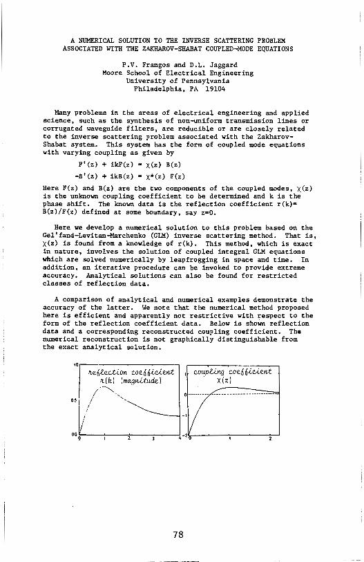
A NUMERICAL SOLUTION TO THE INVERSE SCATTERING PROBLEM ASSOCIATED WITH THE ZAKHAROV-SHABAT COUPLED-MODE EQUATIONS
P.V. Frangos and D.L. Jaggard Moore School of Electrical Engineering
University of Pennsylvania Philadelphia, PA 19104
Many problems in the areas of electrical engineering and applied science, such as the synthesis of non-uniform transmission lines or corrugated waveguide filters, are reducible or are closely related to the inverse scattering problem associated with the ZakharovShabat system. This system has the form of coupled mode equations with varying coupling as given by
F'(z) + ikF(z) x(z) B(z)
-B'(z) + ikB(z) = X*(z) F(z)
Here F(z) and B(z) are the two components of the coupled modes, x(z) is the unknown coupling coefficient to be determined and k is the phase shift. The known data is the reflection coefficient r(k)= B(z)/F(z) defined at some boundary, say z=O.
Here we develop a numerical solution to this problem based on the Gel'fand-Levitan-Marchenko (GLM) inverse scattering method. That is, x(z) is found from a knowledge of r(k). This method, which is exact in nature, involves the solution of coupled integral GLM equations which are solved numerically by leapfrogging in space and time. In addition, an iterative procedure can be invoked to provide extreme accuracy. Analytical solutions can also be found for restricted classes of reflection data.
A comparison of analytical and numerical examples demonstrate the accuracy of the latter. We note that the numerical method proposed here is efficient and apparently not restrictive with respect to the form of the reflection coefficient data. Below is shown reflection data and a corresponding reconstructed coupling coefficient. The numerical reconstruction is not graphically distinguishable from the exact analytical solution.
coup.li.ng coe66ie,lent · x(zl
0 ••••••••• ··-----------·-·-··---·····
!
I oo 0~---'---~---=----~
78

APPLICATION OF BOUNDARY-LAYER THEORY TO INVERSE SCATTERING
H. D. Ladouceur and A. K. Jordan Naval Research Laboratory
Washington, DC 20375-5000 USA
In previous work (J. Optical Soc. Am. A, vol. 2, P• 1916; 1985), we have developed a renormalization technique for the inverse scattering problem associated with electromagnetic waves reflected from inhomogeneous dielectric regions. This renormalization technique relies upon the assumption that the inhomogeneous dielectric region is a continuous and slowly-varying function of spatial position. However, any finite object or surface in free space will always present a discontinuity to an incident electromagnetic wave. In order to extend the renormalization technique to such discontinuous structures, we have applied boundary-layer theory to the renormalization of the electric field within the structure. The resulting electric field is represented as a composite expansion, which is uniformly valid throughout the entire interior region of the structure. The field near the discontinuity at the surface is dominated by the boundarylayer solution, which rapidly decays as a function of depth into the interior of the region. The resulting field in the "deep" interior of the structure is assumed to be given by a slowly-varying electric field. The composite expansion for the electric field provides a kernel to reconstruct discontinuous dielectric profiles from given reflection coefficients. Several numerical examples of this technique are given.
79

NONLINEAR INVERSION TECHNIQUES FOR STRATIFIED DIELECTRICS: THEORY AND EXPERIMENT
D.L. Jaggard, Y. Kim, K. Schultz and P.V. Frangos Moore School of Electrical Engineering
University of Pennsylvania Philadelphia, PA 19104
It is well known that for dense dielectrics and/or for those of large electrical dimension, the linear relation between the refractive index and the reflection coefficient breaks down. This problem has been circumvented in the one dimensional case by use of exact or highly accurate approximate inversion techniques. Here we examine two of these techniques and implement them with swept frequency microwave reflection data from lossless dielectric slabs.
The first technique is an exact method based on the integral equation of Balanis. This equation can be solved analytically for some reflection data and numerically for other data as we have shown previously. The second technique is an approximate method based on a nonlinear renormalization of the Riccati equation which relates the refractive index profile to the local reflection coefficient. We have provided a method for inverting this equation so that the inverse problem can be solved for the refractive index when the reflection data is available.
Below are shown experimental results based on the second technique using bandlimited data (6.1-17.1 GHz) for a 2.54 cm plexiglass slab with refractive index n=l.6. In the figure is shown the application of the approximate nonlinear renormalization technique (dashed line), the linear (Born) reconstruction (dotted line) and the desired result (solid line). Here z is the coordinate from the front face of the slab. Note that the nonlinear renormalization technique significantly decreases both the amplitude and distance errors characteristic of linear techniques.
n 1.8
u
1.2
1.0-
---~--~~---~-~- ~~---··· ' I
1_ - --
2 z(cm)
80
THE DETERMINATION OF CONSTITITT'IVE PARAMETERS FROM THE REFLEcrION AND TRANSMISSION OF A SPHERICAL WAVE
ILLUMINATING A MATERIAL SLAB
F, B, Gross, B, N, Kwan The Florida State University
Department of Electrical Engineering 102 Sducation Building
Tallahassee, FL, 32306
It is of ?ractical importantance to determine the electrical and magnetic properties (permittivity and permeability, respectively,) of arbitrary materials, Since these properties are virtually impossible to predict, they llU.ISt be determined experimentally, Tine danain measurement techniques for closed systems have been investigated (B, Kent, Avionics Laboratory, WPAFB, OH, August 1981) up to the K-band ( 18-26 GHz), In this paper, a frequency domain measurerrent technique is developed for an open system. It is sham how to obtain the permittivity and permeability fran the measuremant of the scattering parameters of an unknown planar material slab illuminated by a spherical wave, This involves an appropriate frequency sarrpling technique, and careful treatment of IJoth the reflected and transmitted waves. Measurement results are presented over a frequency range of 2-18 GHz,
81
A STUDY OF THE ITERATIVE DISTORTED BORN INVERSION FOR PROFILE RECONSTRUCTION
E. Y. Chow·, T. M. Habashy, and W. C. Chew··
• Schlumberger-Doll Research Old Quarry Road
Ridge.field, CT 06877-4108
•• Department of Electrical and Computer Engineering University of Illinois 1406 W. Green St. Urbana, IL 61801
An interative inversion procedure that employs the distorted Born approximation of the .field equations (in source-type integral form) at each iteration bas been proposed in the literature for permittivity and conductivity pro.files reconstruction. It was applied using noise-free simulated data in planar and cylindrical geometries with good results. Since there are several degrees of freedom in the implementation of this inversion procedure (to be discussed below), reconstruction performance is heavily dependent on the specific implementation. In this paper we will examine the behavior of the inversion procedure as a function of implementation.
The various degrees of freedom in implementing the distorted Born inversion procedure are associated with the forward model, the iteration scheme, and the measuremen~ set. Since profiles have to be discretized for computation, one of a variety of discrete forward models, depending on the discretization scheme, can be used in the reconstruction. Together with .finite precision arithmatics, this results in an effective forward model that may be markedly different from the model used to simulate the data. At each iteration step, an optimization problem with several builtin tuning parameters needs to be solved. Together with the choice of these tuning parameters, the choices of initial guess profiles and a convergence (stopping) criterion generally have a significant effect on the result of the iterations. In a realistic application, measurement data are usually incomplete (i.e. data available at finite number of frequencies and/or receiver locations) and noisy. Inversion performance is often sensitive to the usage of such imperfect data. The goal of this paper is to explore the effect of the above implementation considerations on the performance of the distorted Born inversion procedure in a medium with cylindrical stratification (i.e. the permittivity and conductivity pro.files vary only in the radial direction).
82

SIMULTANEOUS INVERSION OF PERMITTIVITY AND CONDUCTIVITY PROFILES OF A CYLINDRICALLY STRATIFIED MEDIUM
USING THE FAST CHOLESKY ALGORITHM
T.M. Habashy and R. Mittra·· • Sclumberger-Doll Research
Old Quarry Rd Ridgefield, CT 06877-4108
.. Department of Electrical and Computer Engineering University of Illinois 1406 W. Green St. Urbana, IL 61801
The problem of profile inversion of a layered medium is an important one and has received considerable attention in the past two decades. However, most of the inversion schemes deal with the reconstruction of either the permittivity or the conductivity profile of a planar stratified medium, from the reflection data gathered with an illuminating plane wave. Little, if any, has appeared in the literature on the problem of simultaneous reconstruction of permittivity and conductivity profiles of a lossy dielectric medium, particularly for the case of a cylindrically stratified medium excited by a dipole-type source.
In this paper we address this problem using the fast Cholesky algorithm, which was employed recently in connection with the inversion of the acoustic wave impedance of a planar stratified medium excited by an impulsive, planar, acoustic wave (A.E. Yagle and B.C. Levy, J. Acoust. Soc. Am. 76-1, 301-308, 1984). In this paper we consider the source to be of dipole-type, one that generates only a TE-polarized wave. The data needed to carry out the inversion is generated from the tangential components of the electric and magnetic fields at the surface, measured as a function of time. This data is preprocessed using a Radon transform in order to obtain a system of two wave components necessary for the development of the fast Cholesky algorithm. Another feature of this work is that it is capable of handling either an impulse or a step excitation, whereas the fast Cholesky algorithm has been applied in the past only with an impulsive-type source.
83
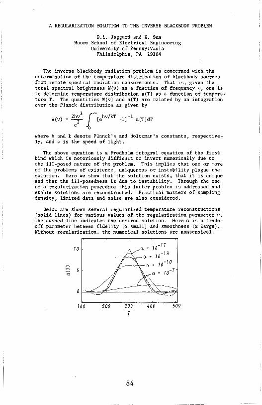
A REGULARIZATION SOLUTION TO THE INVERSE BLACKBODY PROBLEM
D.L. Jaggard and X. Sun Moore School of Electrical Engineering
University of Pennsylvania Philadelphia, PA 19104
The inverse blackbody radiation problem is concerned with the determination of the temperature distribution of blackbody sources from remote spectral radiation measurements. That is, given the total spectral brightness W(v) as a function of frequency v, one is to determine temperature distribution a(T) as a function of temperature T. The quantities W(v) and a(T) are related by an integration over the Planck distribution as given by
W(v) = 2:~3 ~oo[ehv/kT -l]-1 a(T)dT
0
where hand k denote Planck's and Boltzman's constants, respectively, and c is the speed of light.
The above equation is a Fredholm integral equation of the first kind which is notoriously difficult to invert numerically due to the ill-posed nature of the problem. This implies that one or more of the problems of existence, uniqueness or instability plague the solution. Here we show that the solution exists, that it is unique and that the ill-posedness is due to instability. Through the use of a regularization procedure this latter problem is addressed and stable solutions are reconstructed. Practical matters of sampling density, limited data and noise are also considered.
Below are shown several regularized temperature reconstructions (solid lines) for various values of the regularization parameter a. The dashed line indicates the desired solution. Here a is a tradeoff parameter between fidelity (a small) and smoothness (a large). Without regularization, the numerical solutions are nonsensical.
10
c 5 ~
0
100 200 300 T
84
a= 10_77
a= 10-13
10 -10
a= 10 -7
400 500
WYNDHAM C B-7-NUMERICAL METHODS II
Chairman: D.R. Wilton TUESDAY-AM
Page 8:30 CHAIRMAN'S REMARKS 8:40 On the Application ol the "Cosmic Cube" Concurrent Processor to
Moment Method Problems M. P. Hurst and I. K. Strother, TRW.... .. .. .. .. .. .. .. .. .. .. .. .. 86
9:00 Radiation and Scattering from Electrically Small Conducting Bodies of Arbitrary Shape Above An Infinite Ground Plane E. Arvas, Rochester Institute of Technology; R.F. Harrington and J. R. Mautz, Syracuse University. . . . . . . . . . . . . . . . . . . . . . . . . . 87
9:20 Application of an Hybrid-Iterative Technique to a Perfectly Conducting Cube R.P. Penno, P.K. Murthy and G.A. Thiele, University of Dayton. . . . . . . . . . . . . . . . . . . . . . . . . . . . . . . . . . . . . . . . . . . . . . . . . . . 88
9:40 A Comparison of Three Galerkin Solutions for the Displaced Rectangular Waveguide Junction R.W. Scharstein, General Electric; A.T. Adams, Syracuse University.... . . . . . . . . . . . . . . . . . . . . . . . . . . . . . . . . . . . . . . 89
10:00 COFFEE BREAK 1 0:20 Numerical Solutions of Surface Integral Equations for Induced EM
Fields in Biological Bodies X. Min, K.M. Chen and B. Drachman, Michigan State University... . . . . . . . . . . . . . . . . . . . . . . . . . . . . . . . . . . . . . . . . . . . . . . . . 90
10:40 Numerical Solution of TE Scattering by Inhomogeneous Two-Dimensional Composite Dielectric/Metallic Bodies of Arbitrary Cross Section D. Kessler Langan, NASA Johnson Space Center; D.R. Wilton, University of Houston ............................ 91
11 :00 Implementation of the Numerical EM Code (NEC) for Modeling of the VOR Navigation System in the Presence of Parasitic Scatterers K.A. Chamberlin, University of New Hampshire; P.R. Barre, Ohio University....... .. . .. .. .. .. .. .. .. .. . .. .. .. .. 92
11 :20 Modification of the Dual-Finite-Element Method in Electromagnetism; Upper and Lower Bounds to the Characteristic Impedance of Transmission Lines E. Moreno, J. Rivas and J.L. Reboredo, Universidad de Santiago de Compostela, Spain. . . . . . . . . . . . . . . . . . . . . . . . . . . . . . . 93
11 :40 Finite Element Analysis of the Coupling Between a Dielectric Resonator and a Transmission Line F. Hernandez-Gil, Telefonica; J. Perez, E.T.S. Ing. Telecommunicacion, Madrid. . . . . . . . . . . . . . . . . . . . . . . . . . . . . . . . . . . 94
85
ON THE APPLICATION OF THE "COSMIC CUBE" CONCURRENT PROCESSOR TO MOMENT METHOD PROBLEMS
M. P. Hurst and I. K. Strother TRW Space and Technology Group
One Space Park Redondo Beach, CA 90278
The speed and storage capacity of digital computers has increased geometrically since their introduction, but fundamental limits exist and will be approached in the not too distant future. Concurrent processing, i.e., the coordinated use of many processors simultaneously, offers the possibility of extending computing power beyond these limits in the future and provides a means of reducing computing costs in the present. One particular architecture known as the Cosmic Cube has been developed at Caltech and successfully applied to a diverse assortment of scientific computing problems (C. L. Seitz, Communications of the A CM, Vol. 28, pp. 22-33, Jan., 1985). This paper discusses the application of a commercial version of the Cosmic Cube (the Intel iPSC) to the most common numerical method used by researchers in electromagnetics, viz., the method of moments.
In a typical moment method problem the bulk of computational effort is spent filling the coupling matrix, and success in using the Cube hinges upon distributing this task among the processors such that overhead and duplication of effort is minimized, and concurrency is maximized by balancing the computational load between processors. If each matrix element is calculated independently this can be accomplished by simply assigning an equal number of elements to each processor. In a typical application, however, there are symmetries which can be exploited and factors and terms common to several matrix elements, and an efficient code must take advantage these facts. The goal in distributing the element computations is, therefore, to group those elements with common terms and factors on a single processor, where possible, and on a neighboring processor otherwise. Fortunately, matrix elements which share intermediate results are often near neighbors in the coupling matrix, and by arranging the processors in a two-dimensional grid a direct mapping can be made which achieves the above goal. The particular example to be discussed in the presentation is a derivative of the Mautz-Harrington body of revolution code (J. R. Mautz and R. F. Harrington, Tech. Rept. No. TR-77-2, Syracuse University, Syracuse, Feb .. 1977) which the authors were able to adapt to run on the iPSC with minimal modification to the matrix filling algorithm. Comparisons with computations performed on a conventional sequential machine will be made in the presentation.
86
RADIATION AND SCATTERING FRO" ELECTRICALLY SMALL CONDUCTING BODIES OF ARBITRARY SHAPE ABOVE AN INFINITE GROUND PLANE
Ercument Arvas Rochester Institute of Technology
Rochester, NY 14623
Roger F. Harrington and Joseph R. Mautz Syracuse University Syracuse, NY 13210
A simple moment solution is given for low freQuency electromagnetic scattering and radiation problems. A small perfectly conducting body of arbitrary shape is assumed to be placed on or close to an infinite ground plane. The dynamic problem is approximated by two corresponding electrostatic and magnetostatic problems, and each static problem is then solved usinq the Method of Moments. The surface of the perfectly conducting scatterer is modeled· by a set of planar triangular patches. Pulse expansion and point matching testing are used to compute the charge density in the electrostatic problem. For the magnetostatic problem a set of solenoidal vector expansion functions is used. The induced dipole moments are computed from the induced charge and current densities. The scatterer is assumed to be illuminated either by an incident plane wave or by a slowly oscillating dipole placed on the scatterer. Scatterers of various shapes are studied. Specifically a sphere and a sQuare plate above (but close to) the ground plane are considered. From the computed induced dipole moments for a sQuare plate perpendicular to the ground plane, it was concluded that the magnetic (electric) polarizability of two such SQuare plates (apertures in an infinite conducting screen) is larger by about nine percent than the sum of their individual polarizabilities.
Special attention is given to a conducting box on the ground plane. First the box is assumed to be illuminated by a plane wave at grazing incidence and the induced dipole moments are computed. The scattered field is assumed to be produced by these induced dipoles which are placed on the ground plane. Then the box is assumed to have some internal sources and a small slot in its surface. To investigate the efficiency of the narrow slot in transrnitting energy outside, the slot is modeled by a slowly oscillating maqnetic dipole tangent to the surface of the box when the slot is shorted. It is observed that radiation from a narrow slot will be minimal if the slot is on a side face of the box and is oriented perpendicular to the ground plane.
Since the two static problems are decoupled and the Quantities involved in the computations (such as the moment matrix elements> are real, the present method is more efficient, in terms of computer storaqe and time, than an EFIE method of solution which uses the same patching scheme. Also the present method gives more accurate results as the freQuency gets smaller and smaller.
87
',I
APPLIOiTION OF AN HYBRID-ITERATIVE TECHNIQUE TO A PERFECTLY CONDUCTING CUBE
R, P, Penno, P, K, Murthy and G, A, Thiele Graduate Engineering and Research
University of Dayton Dayton, Ohio 45469
An hybrid-iterative approach to solving the MFIE for the surface current density is applied to the case of a three-dimensional body, specifically, a cube, In this method, the currents on the surface of the cube are modeled as the superposition of many right-angled wedge currents, Initially, these component currents are available in closed form as described by Murthy and Thiele [P, K, Murthy, G, A. Thiele, "Non-Uniform Current on a Wedge Illuminated by a TE-Plane Wave," IEEE Trans. Antennas Propagation (to appear)], For regions located approximately one-half wavelength or farther away from the vertex, these currents describe the current density with sufficient accuracy, Beyond one-half wavelength of each vertex, however, the wedge diffraction current dominates the vertex diffraction current, Close to the vertex, then, the MFIE is applied using the closed form wedge current approximation as initial currents, The iteration process described by Murthy, et, al. [P, K, Murthy, G, A, Thiele and K, C, Hill, "A Hybrid Iterative Method for Complex Scattering Problems," IEEE Trans, Antennas Propagation, (to appear)] produces refined or corrected values of the current density, Due to the accuracy of the initial currents used, the convergence is rapid,
It is straightforward to compute the radar cross section (RCS) using the calculated surface current density of the cube, This RCS is then compared with experimentally-derived data, Specifically, the cases of a cube whose sides are three to five wavelengths long are considered where illumination is broadside to a cube face, This will be extended to oblique incidence, Finally, it is expected that this technique will be extended to cubes of arbitrarily large side length,
88
A COMPARISON OF THREE GALERKIN SOLUTIONS FOR THE DISPLACED RECTANGULAR WAVEGUIDE JUNCTION
Robert W. Scharstein General Electric Company Radar Systems Department
Syracuse, NY 13221
Arlan T. Adams Department of Electrical and Computer Engineering
Syracuse University Syracuse, NY 13210
The integral equation for the aperture field at the junction between two rectangular waveguides displaced in the E-plane, H-plane, or both planes is approximately solved by Galerkin's method. The aperture field is projected onto a finite set of three different function spaces; sub-domain pulses, trigonometric waveguide modes that fit the rectangular aperture shape, and weighted Gegenbauer polynomials. The Gegenbauer polynomials are pre-conditioned to satisfy the edge condition at the 90° aperture edge through the weighting factor (A.M. Lerer, V.P. Lyapin, G.P. Sinyavskii, Radiofizika, Vol. 25, No. 8, 1982 and J.D. Hunter, IEEE MTT, Vol. 32, No. 4, 1984).
The elements of the aperture admittance matrix are expressed as infinite summations over waveguide modes of the inner products between aperture functions and waveguide modes. These infinite series must be approximately summed and not truncated, to avoid the 'relative convergence' problem. The numerical convergence properties of the three sets of basis functions are studied. Resultant aperture field distributions, equivalent circuits and scattering parameters are presented for dominant mode incidence. Experimental scattering parameters are also presented for comparison.
89

NUMERICAL SOLUTIONS OF SURFACE INTEGRAL EQUATIONS FOR INDUCED EM FIELDS IN BIOLOGICAL BODIES
Xiaoyi Min, K.M. Chen and B. Drachman* Dept. of Electrical Engr. & Sys. Science, Dept. of Mathematics*
Michigan State University, E. Lansing, Michigan 48824
Consider a biological body being exposed to an incident electromagnetic wave. When the medium wavelength of the incident EM wave is small compared with the dimensions of the body, the induced EM field concentrates mainly in the surface layer of the body due to a small skin-depth. To quantify the induced EM field for this case, some surface integral equations for the induced E and H fields just inside the body surface are derived in tenns of the incident E and H fields. The numerical solutions for these integral equations involve the solution of a large system of linear equations or a large matric problem.
With a super computer (Cyber 205), several numerical methods are investigated for the purpose of solving the surface integral equations. These methods include the conjugate-gradient method, the Gauss-Seidel method and the Jacobi method. Some simple problems are solved first with these methods. The computation time required for each method is compared. The most efficient method is then used to solve the surface integral equations for the induced EM fields in the biological bodies.
To improve the accuracy of numerical results, efforts are made to choose proper basis functions to represent the induced EM field in each partitioned surface cell. The two-dimensional Lagrangian linear basis functions are used to provide the continuity of the EM field, in both normal and tangential components, between adjacent cells. A set of basis functions introduced by Rao et al. (IEEE/APS, 3, 409-418, 1982) is also used. This set of basis functions is suitable for use with triangular patch modeling and it provides the continuity of the nonnal components of both induced electric and magnetic surface currents.
90
NUMERICAL SOLUTION OF TE SCATTERING BY INHOMOGENEOUS TWO-DIMENSIONAL
COMPOSITE DIELECTRIC/METALLIC BODIES OF ARBITRARY CROSS SECTION
Deborah Kessler Langan, NASA Johnson Space Center, Houston, TX 77058 Donald R. Wilton, University of Houston, Houston, TX 77004
In this paper the scattering of composite two-dimensional metallic/dielectric bodies of arbitrary cross section under TE polarized plane wave illumination is considered. The volume polarization current is numerically determined in the dielectric material while the induced surface current is found on metal surfaces. The relative location and cross section of the cylindrical dielectric material and the metal surfaces is completely general; metal surfaces may be embedded in, placed on the surface of, or located exterior to the dielectric material. A volume polarization current integral equation formulation allows inhomogeneous material to be treated. Enforcing the E -field boundary condition on metallic surfaces also permits either open or closed metallic surfaces and junctions of such surfaces to be treated.
The cross section of the dielectric portion of the cylindrical structure is subdivided into triangular regions in each of which the conductivity and permittivity are assumed constant. Any metallic surfaces within the dielectric region are assumed to coincide with triangle edges, resulting in a piecewise linear model of the metallic surface cross section. Use of potential integral representations of the scattered field in the defining equation for the volume polarization current and in the E -field boundary condition on the metallic surfaces yields a pair of coupled integral equations for the induced current density. The numerical modeling of the polarization current in the dielectric region and the integral equation testing procedure is essentially identical to an approach reported earlier. The principal difference is that for metallic edges within the dielectric region, the polarization currents on opposite sides of such edges are independent. On the metallic surfaces, the numerical approach parallels that of the electric field integral equation. Also, the· metal surface junction treatment essentially parallels that used in wire junction problems. An important feature of the approach is that basis functions are chosen which automatically incorporate the correct discontinuity conditions on normal components of polarization current at media interfaces. Results for a number of sample cases are presented and, where possible, are compared with solutions of canonical problems.
91
IMPLEMENTATION OP THE NUMERICAL ELECTROMAGNETIC CODE(NEC) FOR MODELING 'l'HE VOR NAVIGATION SYSTEM
IN THE PRESENCE OP PARASITIC SCATTERERS
Kent A. Chamberlin University of New Hampshire Dept. of ECE Durham, NH 03824-3591
Paul R. Barre' Ohio University Dept. of ECE Athens, OH 45701
A computer model has been developed that estimates bearing error for a VOR airborne navigation system operating in the presence of small, parasitic scatterers such as antennas, antenna masts, and guy wires. This model, which is written in VMS batch commands and FORTRAN 77, interacts with an unmodified version of NEC-2 to obtain pertinent scattered-field data. These data are then used to calculate the composite field, and indicated bearing, at the airborne receiver location. Comparisons of modeled data with measured data indicate that this modeling approach is valid. The puropse of thispresentation is to give some of the insights gained while working with NEC for this type of application. The work discussed here was funded by the Federal Aviation Administration under Contract DTFAOl-85-Y-01020.
The azimuth angle of an aircraft with respect to a VOR station is determined by the phase of the received audio sinusoid generated by a limacon pattern that rotates in space due to appropriate time-varying phasing between four Alford loop antennas. To model the effects of scatterers on system accuracy, each loop antenna is modeled alone in the presence of the scatterer using NEC and field data are recorded for a far-field orbit around the source-scatterer configuration1 this process is repeated for each of the four loop antennas thus providing complete information about complex path loss between each loop antenna and the observation point in the presence of the scatterer. The received audio waveform is then constructed at each observation point by applying the appropriate modulation to each of the loop antennas, adjusted by the complex loss values given by NEC. The phase and distortion of the received audio waveform is determined using a Fast Fourier Transform algorithm.
The key points to be addressed include approximations for modeling the Alford Loop antennas, which involves attempts at surface patch excitation, representations of various parasitic scatterers and the ground plane, model diagnostics, and comparisons of modeled and measured data.
92

MODIFICATION OF THE DUAL-FINITE-ELEMENT METHOD IN ELECTROMAG
NETISM: UPPER AND LOWER BOUNDS TO THE CHARACTERISTIC IMPEDAN+
CE OF TRANSMISSION LINES.-
E. MORENO, J. RIVAS and J.L. REBOREDO
Dpto. Electricidad y Magnetismo
Facultad de Fisica
Universidad de SANTIAGO DE COMPOSTELA
SPAIN.
ABSTRACT
Prof. Hammond has already discussed the physical bases necessary to establish a dual-variational method in problems of electromagnetics fields ( Clarendon-Press, Oxford,1981 ). Later, this method was complemented by the finite-element method ( IEE Proc.,130,A,3,105-111,1983). Penman and Fraser have carried out mathematical studies on magnetic problems ( IEEE trns. on Magn. 18,2,319-324,1982 ). A modification of the dual-finite-element method used to calculate energy parameters ( R,L,C ) is presented. This modification consist of a previous transformation of single connected zones to the other multiply connected equivalents,to which the duality is applied alternatively, with a resulting analitic and computational simplication.
The described method is used to calculate the characteristic impedance of transmission lines ( TEM ); energy functionals which limit the <11proximations are analysed. The lagrange system is obtained topologically. The application of the proposed method to the calculation of monodimensional systems one may rapidly obtain an excellent approximation, even to the exact value. In systems of more than one dimension the problem remains the problem of confiden ce limits for the upper and lower bounds. However, better results -are achieved than ordinary methods.
The paper also attemps to simplify the essential steps of pre-processing of data while maintaining flexibility of the method.
The main emphasis of the paper is the new method : we have obtained a more convergent result with a reduction in computational time. The application of the method to non-linear systems is also a future possibility.
93

*
FINITE ELEMENT ANALYSIS OF THE COUPLING BETWEEN A DIELECTRIC RESONATOR AND A TRANSMISION LINE
* ** F. Hernandez-Gil , J. Perez
** R&D Dpt., Telef6nica, Lerida 43, 28020 Madrid, Spain. Microwave Dpt.,E.T.S.Ing.Telecomunicaci6n,28040 Madrid,Spain.
A theoretical method to calculate the external quality factor of an axisymmetric dielectric resonator coupled to a transmission line has been developed. The finite element method was used to solve both the transmission line and the dielectric resonator. This method provides flexibility in the analysis of both structures.
The resonant frequency and the field distribution of the resonator are calculated using a finite element procedure (F.Hernandez, 1985 MTT-S, pp.485-488). The field distribution and the propagation constant of the transmission line are calculated at the resonant frequency. A finite element formulation with the axial components of the field is used (N. Mabaya, MTT-29, pp.600-605). The external quality factor is calculated expanding the resonator field into transmission line eigenmodes to evaluate the power dissipated in the line.
This method does not require the evaluation of the transmission line characteristic impP.dance. The procedure can be applied to calculate the coupling hetween resonators with different shapes (cylindrical, ring, double, etc.) transmission lines (waveguides, microstrip, fin-line, etc.).
and
The coupling between a cylindrical dielectric resonator and a fin-line (fig.1) has been calculated with this method and studied as a function of the most relevant parameters of the structure (distance between the fin-line gap and the resonator, location of the resonator, fin-line parameters, etc.). Several experimental measurements have been carried out to test the validity of the method and good agreement with the calculated results was observed.
94

PHILA. NORTH B-8-SCATTERING I
Chairman: L. Wilson Pearson TUESDAY-AM
Page 8:30 CHAIRMAN'S REMARKS 8:40 Analysis of an Open-Ended Elliptical Waveguide in a Planar
Stratified Medium T.M. Habashy, Schlumberger-Doll Research; W.C. Chew, University of Illinois; J. F. Kiang, MIT.............. . . .. . .. . . .. . 96
9:00 On the EM Scattering by an Open-Ended Dielectric Loaded Rectangular Cavity in a Ground Plane J.R. Lyons, Jet Propulsion Lab; P.H. Pathak, Ohio State University ............................................. 97
9:20 Asymptotic Theory of Scattering by Cylinders Comprising Multiple Layers of Different Materials L. W. Pearson, McDonnell Douglas Research Laboratory.. .. . .. .. 98
9:40 Scattering from a Perfectly Conducting, Finite, Open Cylinder, Coated with a Thin, Homogeneous Dielectric Layer P.L. Huddleston, McDonnell Douglas Research Laboratory ....... 99
10:00 COFFEE BREAK 10:20 Numerical Solution of Electromagnetic Scattering Problems
Involving Homogeneous Dielectric Bodies Via a Single Integral Equation A.W. Glisson, University of Mississippi; 8.1. Sholy, Avionics Engineering Technology .............................. 100
1 0:40 Electromagnetic Scattering From a Dielectric Body Using Physical Optics D.J. Janse Van Rensburg, J.A.G. Malherbe and D.A. McNamara, University of Pretoria ........................ 101
11 :00 High Frequency Scattering from a Coaled Cylinder in Which the Relative Permittivity of lhe Coating is Less Than Unity J.M. Dunn, Sandia National Laboratories ...................... 102
11 :20 Electromagnetic Scattering By Two Parallel Dielectric Prolate Spheroids B.P. Sinha and M.F.R. Corray, Memorial University of Newfoundland ............................................. 103
11 :40 Dipole-At-A-Complex-Point Approximation of Small and Medium Sized Sources and Dielectric Scatters L.V. Lindell and K. Nikoskinen, Helsinki University of Technology. . . .. .. .. .. .. .. . . . . . . . . . . .. .. .. .. .. . . . . .. .. .. . 104
95

ANALYSIS OF AN OPEN-ENDED ELLIPTICAL WAVEGUIDE IN A PLANAR STRATIFIED MEDIUM
T.M. Habash/, W. C. Chew~·. and J.F. Kiang° ..
Schlumberger-Doll Research, Old Quarry Rd, Ridgefield, CT 06877-4108 ••Dept.of Electrical and Computer Engineering, Univ. of Illinois,
Urbana, IL 61801 •••Dept.of Electrical Engineering and Computer Science, MIT, Camb., MA 02139
The radiation of a flanged open-ended elliptical waveguide, which is excited by an arbitrary incident waveguide mode, a point source or a probe, into a planar stratified medium, is investigated analytically. The complexity of analyzing the discontinuity at the waveguide aperature stems from the fact that the electromagnetic field is mainly vector in nature. Also, the necessity of matching the discrete modes inside the waveguide to the continuum radiation modes in the open space makes the bookkeeping process cumbersome. A vector Mathieu transform together with a vector Mathieu series are developed and their properties are discussed, which help facilitate the analysis and simplify the process of matching the boundary conditions at the waveguide aperture.
The vector Mathieu transform is introduced to express the continuous spectrum of radiation modes in the planar stratified medium whereas the vector Mathieu series helps in providing a convenient bookkeeping technique for representing the discrete modal spectrum inside the waveguide. With the help of the orthogonality relationships of these operators, mode matching at the waveguide junction can be carried out in a simple manner and hence allows us to compute the transmission and reflection operators at the plane of discontinuity. These transmission and reflection operators represent the mode conversion physics at the discontinuity.
96

ON THE EM SCATTERING BY AN OPEN-ENDED DIELECTRIC LOADED RECTANGULAR CAVITY IN A GROUND PLANE
James R. Lyons Jet Propulsion Lab., Califonia Inst. of Technology
Pasadana, CA. 91109
P.H. Pathak The Ohio State University
ElectroScience Lab. Department of Electrical Engineering Columbus, Ohio 43212
Efficient moment method (MM) based approaches are investigated for analyzing the problem of EM plane wave scattering by an open ended, perfectly-conducting , two dimensional dielectric loaded rectangular cavity in a ground plane. An integral equation for the unknown electric field in the aperture at the open end is obtained via the use of special Green's function for the conducting half space and the cavity,respectively. The cavity Green's function is represented by a rapidly convergent expansion in terms of modes propagating parallel to the aperture rather than transverse to it. Next, Galerkin 's method is used to obtain the MM equations. For small to moderatly large apertures, the unknown aperture field is represented by a set of conventional waveguide modes as the basis functions. This approach appears to be more efficient than one employing subsectional basis functions, and it works even for near grazing incidence. In the case of backscatter from deep cavities only a few selected modes are necessary for describing the aperture field. For electrically large apertures and cavities which are not too deep, the aperture field is expressed as a hybrid commbination of the known geometrical optics field together with a pair of oppositely traveling surface wave basis functions (if surface waves exist) and a set of basis functions near the aperture edges. Such a hybrid represetaion with just a few unknowns (with the number of unknowns being independent of the aperture size) is far more efficient than using a large number of conventional subsectional basis set in the case of large apertures. Additional ways to analyze this scattering problem will also be discussed, and the accuracy of the results obtained by the above approaches will be indicated by comparison with results based on a conventional MM analysis.
97
ASYMPTOTIC THEORY OF SCATTERING BY CYLINDERS COMPRISING MULTIPLE LAYERS OF DIFFERENT
MATERIALS
L. Wilson Pearson McDonnell Douglas Research Laboratories
P. O. Box 516 Saint Louis, MO 63166
The angular propagation around a metallic cylinder clad by a single lossless dielectric layer has been studied by a number of researchers, most notably Elliott (J. Appl. Phys.,~. 368-376, 1955), who did the original work on this subject. Recently, computational capability has been developed for the application of Elliott's concepts to multilayered regions, including the effects of non-normal incidence and of material losses (L.W. Pearson, North Am. Radio Sci. Meeting, Vancouver, B.C., June, 1985; L.W. Pearson, National Radio Sci. Meeting, Boulder, CO, Jan., 1986). The multilayer formulation can be put into a ray-optical format so that coated cylinders can be incorporated into the collection of GTD (geometrical theory of diffraction) canonical shapes.
The most notable complication introduced by the presence of the dielectric layers occurs in the illuminated-to-shadow transition region. It is necessary to evaluate numerically the spectral integral over angular wave-numbers in this region. The Bessel functions that appear in the integrand are approximated by their Airy function representations in the course of this numerical integration, and the resulting functions have traditionally been represented variously as Fock functions, Pekeris caret functions, or simply termed transition functions (c.f. P.H. Pathak, Radio Sci., 14, 419-435, 1979). For impedance-surface cylinders these 'i'iiiictions have been extensively tabulated in a Lockheed report by Logan and Yee (1959).
In this presentation, it is shown that the transition region integrals for the penetrable case can be expressed in a form identical to that of the surface impedance case, but in which the formerly constant impedance function becomes dependent on the variable of integration. Because dissimilar materials are present, Bessel functions of different arguments appear in this function, and recourse to the uniform asymptotic representations of Bessel functions is required. (In previous transition function developments, only a single number appears in the argument of the various Bessel functions present.) These representations are a 11 ttle more complicated than the simpler Airy function representations, however, so that the complexity of the integrand increases principally through the number of different materials present and its numerical integration seems well within the scope of present-day computers. The analysis leading to the foregoing statements is presented, and observations about its computability are made.
98
SCATTERING FROM A PERFECTLY CONDUCTING, FINITE, OPEN CYLINDER COATED WITH A THIN, HOMOGENEOUS DIELECTRIC LAYER
P. L. Huddleston McDonnell Douglas Research Laboratories
P.O. Box 516 St. Louis, Missouri 63166
A formulation of electromagnetic scattering from coated cylinders is developed for the case of an infinitesimally thin, perfectly conducting, circular cylinder coated with a thin uniform layer of dielectric material. The surface equivalence principle is applied to obtain a system of integral equations relating the unknown equivalent surface currents. The layer, which may coat the inner or outer surface of the conductor, is assumed to be thin enough that surface currents on the ends of the layer can be neglected. The method of moments with entire domain expansion and testing functions is used to solve the system of integral equations numerically. Results of calculations for various cylinder aspect ratios, layer thicknesses, and coating constitutive properties are presented. The computational results are compared with experimental data.
99
ROMEIUCAL SOL1JI'ION OF ELECl'ROIIAGDTIC SCATIERIRG PROBLEMS IRVOLVIRG BOIIOGENEOUS DIELECl'RIC
BODIES VIA A SINGLE Ill'l.'EGBAL EQUATION
Allen W, Glisson Department of Electrical Engineering
University of Mississippi University, MS 38677
Beshara I, Sholy Avionics Engineering Technology
Parks College Cahokia, IL 62206
Electromagnetic scattering problems involving homogeneous dielectric bodies can be modeled using a single surface integral equation formulation, as opposed· to the usual coupled surface integral equation method, In the single integral equation formulation, the number of unknowns required to model the dielectric scatterer is reduced by analytically eliminating one of the equivalent surface currents, either the electric current J or the magnetic current M, at the dielectric body surface, the resulting integral equation can be solved for the remaining equivalent surface current. This surface current may then be used to compute the scattered field via radiation in a homogeneous medium, Additional computations would be required if it is desired to compute the field interior to the scatterer surface,
In this paper a relatively simple numerical implementation for the solution of scattering by homogeneous dielectric bodies via the single integral equation approach is considered, The numerical procedure is developed in such a way that portions of existing algorithms for perfectly conducting scatterers may be easily combined to yield the program for dielectric scatterers. Advantages and disadvantages of the approach are discussed, The procedure is applied for cases involving two-dimensional geometries and for both 1E and TM illuminations, Results are presented for computed surface current density and radar cross section for cylinders having various dielectric constants, Data obtained with the method are also compared with results obtained via other applicable methods,
100
ELECTROMAGNETIC SCATTERING FROM A DIELECTRIC BODY USING PHYSICAL OPTICS
D.J. JANSE VAN REMSBURG, J.A.G. MALHERBE and D.A. MCNAMARA
Department of Electronic Engineering, University of Pretoria, Pretoria, South Africa
Exact methods are not usually suitable for finding the scattering from hollow dielectric scatterers of practical interest. One approximate technique uses the volume equivalence principle current J = jwEle-ed by assuming E to be the incident field (a Kirchoff type approximation). However, this requires that a volume integral be performed, which besides being time-consuming, is not easily incorporated into existing physical optics codes for conducting scatterers, which deal only with surface integrals. A surface current formulation is preferred even for dielectric scatterers.
This paper describes a direct method of calculating the electromagnetic backscatter from a complex hollow dielectric body. Electric and magnetic surface equivalence currents are defined on the surface of the dielectric body and the scattered far fields calculated from the appropriate vector potentials. The fields on the surface of the dielectric body are obtained by making use of the directional impedances (and the reflection coefficients calculated therefrom) for infinately large planar dielectric slabs.
For a smooth shaped dielectric body with a thickness much smaller than the radius of curvature of the surface, the assumption is made that at each point on the surface the equivalence currents can be found from the reflection coefficients of the planar slab of equivalent thickness at that point, taking into account the correct angle of incidence. These currents are then integrated over the illuminated portion of the scattering surface to find the required scattered fields.
The theory presented differs from conventional physical optics in that the reflection coefficients contained inside the radiation integral are functions of both angular variables.
Comparisons between computed and measured results for simple shapes (e.g. finite dielectric plates, dielectric half-cylindrical shell) will be presented.
*******************~*
101

HIGH FREQUENCY SCATTERING FROM A COATED CYLINDER IN WHICH THE RELATIVE PERMITTIVITY OF THE COATING
IS LESS THAN UNITY
John M. Dunn Division 7553
Sandia National Laboratories P.O. Box 5800
Albuquerque, New Mexico 87185
In this talk we examine the problem of high frequency scattering from an infinite cylinder which is coated with a dielectric. The relative permittivity of the dielectric is less than that of the surrounding medium. The problem is chosen as a prototype for the study of scattering from objects with a multiple number of layers, the permittivity of which may be chosen in such a way as to allow layers with higher relative permittivities to be placed over those with lower ones. It is found that there are two contributions to the fields. The first contribution is from the l~cal scattering of the incident wave by the cylinder in a manner essentially the same as geometrical optics. The magnitude of the scattering can be well approximated by the use of an impedance boundary condition. The second contribution comes from a wave which travels through the dielectric layer. This wave is approximated in one of two ways. For points on the surface which lie well within the illuminated region, the field is found by first calculating the field resulting from scattering by a magnetic conductor, and then using this field as a boundary condition to calculate the fields in the dielectric region. This procedure allows the media to be separated from one another. For points well within the shadow region, the wave can be approximated as coming from a magnetic dipole placed in the center of the illuminated region. The strength of this dipole is found by integrating the electric field found from the magnetic conductor approximation over the surface of the cylinder. The results are seen to agree well with the exact solution available for the problem. Hopefully, it will be possible to generalize the procedure to objects whose geometries do not allow an explicit analytical solution, although this work is not carried out here.
102
ELECTROMAGNETIC SCATTERING BY TWO PARALLEL DIELECTRIC PROLATE SPHEROIDS
B.P. Sinha and M.F.R. Cooray Faculty of Engineering and Applied Science
Memorial University of Newfoundland St. John's, NF, Canada AlB 3X5
The multipole expansion technique applied by the authors (January 13-16, 1986 URS! Meeting, Boulder, Colorado) to the scattering from a single dielectric prolate spheroid of refractive index n2 embedded in an infinite homogeneous and isotropic dielectric medium of refractive index n 1 propagating the incident plane electromagnetic wave with arbitrary
+(a) polarization and angle of incidence employing M vectors for
+(a) +(a) E-field expansion and N vectors for H-field expansion [M • + A A A A A +(a) 1 + +(a) V $(h;~,n.~) x a, a• (x,y,z); N • 'It V x M J has been used in the present problem together with the translational addition theorems for spheroidal vector wave functions (B.P. Sinha and R.H. MacPhie, Quart. Appl. Math., 38, 143-158, 1980). The translational addition theorems which transform the outgoing wave from one spheroid into the incoming wave at the other spheroid
+(a) +(a) assume the simplest form for M and N vectors because they translate like a scalar wave function $(h;~,n,t) (B.P. Sinha and R.H. MacPhie, IEEE Trans. AP, 31, 294-304, 1983). The interacting spheroids are assumed to be composed of the same dielectric material.
The general solution for a N-body system of dielectric prolate spheroids is obtained in the form S = [G] I, where Sand I are respectively the colUlllll vectors of the coefficients of the series expansions of the scattered and transmitted fields taken together and the incident field. (GJ is the transformation matrix which depends only upon the geometries and spacing of the scatterers. Numerical results in the form of curves of scattering cross-sections are given for varieties of two body systems of parallel dielectric prolate spheroids.
103
DIPOLE-AT-A-COMPLEX-POINT APPROXIMATION OF SMALL AND MEDIUM SIZED SOURCES AND DIELECTRIC SCATTERERS.
Ismo V. Lindell, Keijo Nikoskinen Helsinki University of Technology, Electromagnetics Laboratory
Otakaari SA, SF-02150 Espoo 15, FINLAND
Classical multipole theory valid for radiation from sources with small dimensions is extended to multipoles with source points in complex space.
It is shown that, in general, the approximation by an electric dipole or a combination of an electric and a magnetic dipole is improved if their location is chosen in a suitable manner, instead of taking the origin or some geometrically obvious point. The optimal point will in general be in complex space. An expression for the complex location is derived which minimizes the effect of the second-order multipole so that the firstorder multipole will be most ·dominating. From a simple example, radiation from a cubic source with a propagating current wave, it is seen that the radiation characteristic will be an order of magnitude in L/A better for the dipole approximation when the dipole is the optimal complex point instead of being at the center of the cube. Simultaneously, it is demonstrated that the validity of the dipole approximation is extended from L<<A to about L(A/2, L being the measure of the source.
Complex locations for the approximating electric dipoles of dielectric spherical or spheroidal scatterers are found through integral equation analysis for a propagating incident wave. Other incident waves and generalizations of the theory are also discussed. Some numerical data are presented to find limits of applicability for the present dipole-at-a-complex-point approximation.
104

SALON 3/4 B-9-INVERSE SCATTERING II (MULTIDIMENSIONAL IMAGING)
Chairman: W.M. Boerner TUESDAY-AM
Page
8:30 CHAIRMAN'S REMARKS 8:40 Microwave Diversity Imaging with Near Optical Resolution
N.H. Farhat and Y. Shen, University of Pennsylvania; T.H. Chu, RCA; C.L. Werner, JPL. ........................... 106
9:00 A High Frequency Inverse Scattering Model for Smooth, Convex, Conducting Scatterers in the Slightly Bistatic Case Bing-Yuen Foo and W.M. Boerner, University of Illinois; S.K. Chanduri, University of Waterloo ........................ 107
9:20 Accurate Reconstruction of Two-Dimensional Convex Conducting Target Shapes From a Single-Point TM Scattered Field Pulse Response M. Strickel and A. Taflove, Northwestern University; K. Umashankar, University of Illinois .............. 108
9:40 Microwave Diversity Imaging of Objects in the Presence of Severe Clutter N. H. Farhat and Y. Shen, University of Pennsylvania .......... 109
10:00 COFFEE BREAK 10:20 Radar Cross-Section Management Studies Employing Microwave
Diversity Imaging N.H. Farhat, H. Li and Y. Shen, University of Pennsylvania ..... 110
10:40 Microwave Diffraction Imaging of a Point Source in a Dielectric K. Schultz and D.L. Jaggard, University of Pennsylvania ....... 111
11 :00 Vector Diffraction Tomography in Computer Assisted Electromagnetic Imaging B.D. James and W.M. Boerner, University of Illinois ........... 112
11:20 Tomographic Imaging of 3-D Incoherent Objects Employing Spectrally Selective Correlation Measurements C.L. Werner and N.H. Farhat, University of Pennsylvania ...... 113
11:40 A Survey of Image-Embedded Passive Beamforming Sources for a Radio Camera J. Halat and B.D. Steinberg, University of Pennsylvania ....... 114
105
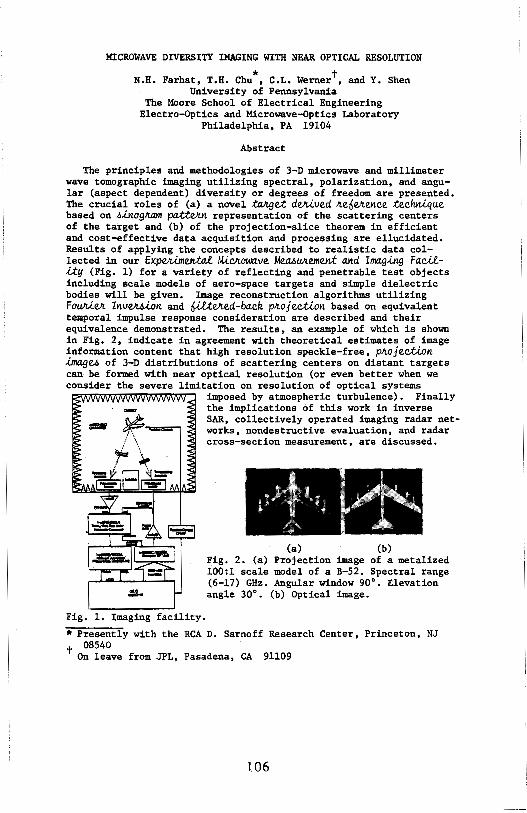
MICROWAVE DIVERSITY IMAGING WITH NEAR OPTICAL RESOLUTION
"' t N.H. Farhat, T.H. Chu , C.L. Werner, and Y. Shen University of Pennsylvania
The Moore School of Electrical Engineering Electro-Optics and Microwave-optics Laboratory
Philadelphia, PA 19104
Abstract
The principles and methodologies of 3-D microwave and millimeter wave tomographic imaging utilizing spectral, polarization, and angular (aspect dependent) diversity or degrees of freedom are presented. The crucial roles of (a) a novel talc.get de.JLi.ved ~e6eJr.ence techn.i.que based on ~.i.nogltam pa.tt~ representation of the scattering centers of the target and (b) of the projection-slice theorem in efficient and cost-effective data acquisition and processing are ellucidated. Results of applying the concepts described to realistic data collected in our ExpeJu.men.ta.e. M.l~owave Mea.6~eme.n.t and Imag.i.ng Fac..il.-lty (Fig. 1) for a variety of reflecting and penetrable test objects including scale models of aero-space targets and simple dielectric bodies will be given. Image reconstruction algorithms utilizing Foun.leJr. Inv~.i.on and ·6.llteJr.ed-back p~ojec:tlon based on equivalent temporal impulse response consideration are described and their equivalence demonstrated. The results, an example of which is shown in Fig. 2, indicate in agreement with theoretical estimates of image information content that high resolution speckle-free, pJtojec:tlon ~U of 3-D distributions of scattering centers on distant targets can· be formed with near optical resolution (or even better when we consider the severe limitation on resolution of optical systems
Fig. 1 •. Imaging facility.
imposed by atmospheric turbulence). Finally the implications of this work in inverse SAR, collectively operated imaging radar networks, nondestructive evaluation, and radar cross-section measurement, are discussed.
(a) (b) Fig. 2. (a) Projection image of a metalized 100:1 scale model of a B-52. Spectral range (6-17) GHz. Angular window 90°. Elevation angle 30°. (b) Optical image.
* Presently with the RCA D. Sarnoff Research Center, Princeton, NJ t 08540
On leave from JPL, Pasadena, CA 91109
106
A MGB FRIQJ]!K:r INVERSB SCA'1"l'ERDG llllBL !'CE. SlllOTB, CXffiBX, <XJUx:'l'IR; SCATmaERS IN 'DIE SLIGB'l'LY BIS'IM'IC CASE
Bing-Yuen Foo and WOlfgang-M. Boemer CODllll.lOications Laboratory, SEL-4210
Department of Electrical Engineering & Computer Science (111/c 154) tJni¥ersity of Illinois at Chicago
A8S'DIAC'l'
Chicago, IL 60680-4348 and
SUjeet K. Chaudhuri Department of Electrical Engineering
university of waterloo waterloo, Ontario, N2L 3Gl canada
'11leories of physical optics far-field inverse scattering have been developed and applied to target imaging with varying degrees of success by many researchers for the monostatic case. In this work, an early time expression for the impulse response of a smooth, convex, conducting target is derived under the physical optics assumption in the slightly bistatic case. The expression is found to be an extension of the Kennaugh-Cosgriff formula for the monostatic case (Kennaugh and Cosgriff, IRE Nat'l conv. Rec., Part, I, 1958), and also in the bistatic case, it is proportional to the second derivative of some silhouette area function of the target. However, under the PO assumption, the early time expression does not manifest depolarization effects. Certain polarization corrections to the PO formulation can be accomplished in the bistatic case by extending Bennett's polarization correction in the monostatic case through his space-time integral equation approach and his leading edge assumptions. By incorporating such a bistatic polarization correction into the early time physical optics impulse response, and Fourier-transforming to the frequency domain, a high frequency inverse scattering model is obtained.
Recovery of geometrical information about the specular region of the target such as specular curvatures, target orientation and cross-sectional area functions can be made possible with the use of our results from the knowledge of the bistatic polarimetric data. For target profile recovery, braodband polarimetric measurements are required for all aspects, as in the backscattering case (Boemer, Ho & Foo, IEEE Trans. AP-S, Special Issue, March 1981). It is found that polarization correction of Kennaugh's ramp response concept and Radon's concept of shape reconstruction from cross-sectional areas can be combined and applied to bistatic radar target imaging which should result in a useful tool for bistatic radar target interrogation.
107

ACCURATE RECONSTRUCTION OF TWO-DIMENSIONAL CONVEX CONDUCTING TARGET SHAPES FROM A SINGLE-POINT TM SCATTERED FIELD PULSE RESPONSE
Mark Strickel and Allen Taflove EECS Department, Northwestern University
Evanston, IL 60201
Korada Umashankar EECS Department, University of Illinois at Chicago
Chicago, IL 60680
This paper reports the use of the finite-difference time-domain (FD-TD) method to accurately reconstruct the shape of two-dimensional convex conducting targets from a single-point TM scattered field pulse response. The general approach involves setting up a numeri ca 1 feedback loop which uses a 2-D FD-TD code as a forward-scattering element, and a nonlinear optimization code as the feedback element. FD-TD generates a test pulse response for a proposed target shape. The test pulse is compared to a measured pulse, and an error signal is developed. Working on this error signal, the nonlinear optimization element perturbs the ori gi na 11 y proposed target shape in a manner to drive down the error. Upon repeated iterations, the proposed target shape ideally converges to the actual shape.
The advantage of working in the time domain is that a target shape can be reconstructed sequentially in time as the incident pulse moves across the target, taking advantage of causality. This reduces the complexity of reconstruction since only a portion of the target shape is being generated at each iteration.
Detailed target reconstruction begins by locating the point on the scatterer that is first illuminated by the incident pulse. The 1 atti ce points adjacent to the initial point are then perturbed by sequentially assigning them high values of conductivity. The new addition to the target surface is obtained by comparing the scattered electric field values (observed at a single point) for each perturbation with the measured values, and selecting the surface perturbation that gives the best agreement with measured data in the least-squares sense. This process is repeated using the target surface points generated in the previous iteration as the base from which to launch the new surface perturbation. In this manner, the actual target surface contour is generated synchronously as the leading edge of the incident pulse moves across the target.
This technique has been successfully used to accurately reconstruct simple convex target shapes such as triangles and rectangles. Currently, the "measured" input data is generated by a very high resolution forward FD-TD code for a half-sine incident pulse, and reconstruction is accomplished with a coarser resolution FD-TD code. Efforts are now underway to obtain actual measured data for such 2-D targets. Preliminary indications are that measurement errors may primarily affect reconstruction of the target shape in shadow regions.
108
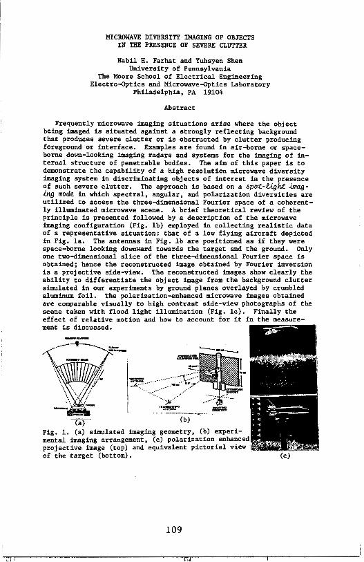
MICROWAVE DIVERSITY IMAGING OF OBJECTS IN THE PRESENCE OF SEVERE CLUTTER
Nabil H. Farhat and Yuhsyen Shen University of Pennsylvania
The Moore School of Electrical Engineering Electro-Optics and Microwave-Dptics Laboratory
Philadelphia, PA 19104
Abstract
Frequently microwave imaging situations arise where the object being imaged is situated against a strongly reflecting background that produces severe clutter or is obstructed by clutter producing foreground or interface. Examples are found in air-borne or spaceborne down-looking imaging radars and systems for the imaging of internal structure of penetrable bodies. The aim of this paper is to demonstrate the capability of a high resolution microwave diversity imaging system in discriminating objects of interest in the presence of such severe clutter. The approach is based on a .6pot-Ught .unag.lng mode in which spectral, angular, and polarization diversities are utilized to access the three-dimensional Fourier space of a coherently illuminated microwave scene. A brief theoretical review of the principle is presented followed by a description of the microwave imaging configuration (Fig. lb) employed in collecting realistic data of a representative situation: that of a low flying aircraft depicted in Fig. la. The antennas in Fig. lb are positioned as if they were space-borne looking downward towards the target and the ground. Only one two-dimensional slice of the three-dimensional Fourier space is obtained; hence the reconstructed image obtained by Fourier inversion is a projective side-view. The reconstructed images show clearly the ability to differentiate the object image from the background clutter simulated in our experiments by ground planes overlayed by crumbled aluminum foil. The polarization-enhanced microwave images obtained are comparable visually to high contrast side-view photographs of the scene taken with flood light illumination (Fig. le). Finally the effect of relative motion and how to account for it in the measurement is discussed.
~--······~::~~--:_~_-_._:_s;:. -: ..
. - -~--.--.--(b)
Fig. 1. (a) simulated imaging geometry, (b) experimental imaging arrangement, (c) polarization enhanced projective image (top) and equivalent pictorial view of the target (bottom).
109
. ... . ... .. - -•"F-:;;;:r-~~ "q ~ ,.. ... . • .. l ...
" -~ J,~·P-', ~ (c)
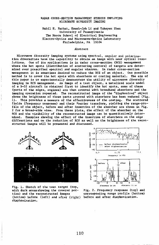
RADAR CROSS-SECTION MANAGEMENT STUDIES EMPLOYING MICROWAVE DIVERSITY IMAGING
Nabil H. Farhat, Hsueh-Jyh Li and Yuhsyen Shen University of Pennsylvania
The Moore School of Electrical Engineering Electro-Optics and Microwave-Optics Laboratory
Philadelphia, PA 19104
Abstract
Microwave diversity imaging systems using s~ectral, angular and polariza-tion diversities have the capability to obtain an image with near optical resolutions. One of its applications is in radar cross-section (RCS) management where the hot spots (distribution of scattering centers) of targets are determined over prescribed spectral and angular windows. In radar cross-section management it is sometimes desired to reduce the RCS of an object. One possible method is to cover the hot spots with absorbers or coating material. The aim of this paper is to experimentally demonstrate the utility of microwave diversity imaging in RCS management. An image of a test object, a metalized scale model of a B-52 aircraft is obtained first to identify the hot spots, some of these (parts of the edges, engines) are then covered with broadband absorbers and the imaging operation repeated. The reconstructed image of the "diaphonized" object shows the brightness of those parts covered with absorbers has been reduced (Fig. 1). This provides a measure of the effectiveness of the coating. The scattered fields (frequency response) and their Fourier transform, yielding the range-profile of the object, before and after insertion of the absorber are shown in Fig. 2 for a broad-side view. From these plots, the effect of the absorber on the RCS and the visibility of the reconstructed image can be quantitatively determined. Examples showing the effect of the insertion of absorbers on the edge diffractions and on the reduction of RCS as well as the brightness of the reconstructed images will be presented and discussed.
Fig. 1. Sketch of the test target (top, with dark areas shpwing the covered portion) and the reconstructed images (bottom) before (left) and after (right) diaphonization.
llO
~'4A·fv1dJvA1\·,rv1 _____________ !_~-~i}r~ '
before diaphonization after diaphonization
-40 L----'----'------'----~ 6.0 11. 75
Frcqu~ncy in (:llz
17.5
distance in cm distance in cm
Fig. 2. Frequency response (top) and corresponding range profile (bottom) before and after diaphonization.
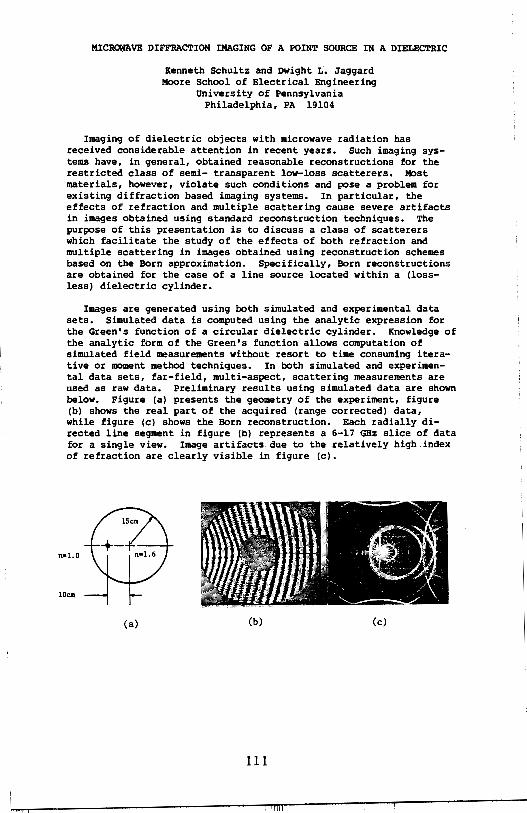
MICR~VE DIFFRACTION IMAGING OF A POINT SOURCE IN A DIELECTRIC
Kenneth Schultz and Dwight L. Jaggard Moore School of Electrical Engineering
University of Pennsylvania Philadelphia, PA 19104
Imaging of dielectric objects with microwave radiation has received considerable attention in recent years. Such imaging systems have, in general, obtained reasonable reconstructions for the restricted class of semi- transparent low-loss scatterers. Most materials, however, violate such conditions and pose a problem for existing diffraction based imaging systems. In particular, the effects of refraction and multiple scattering cause severe artifacts in images obtained using standard reconstruction techniques. The purpose of this presentation is to discuss a class of scatterers which facilitate the study of the effects of both refraction and multiple scattering in images obtained using reconstruction schemes based on the Born approximation. Specifically, Born reconstructions are obtained for the case of a line source located within a (lossless) dielectric cylinder.
Images are generated using both simulated and experimental data sets. Simulated data is computed using the analytic expression for the Green's function of a circular dielectric cylinder. Knowledge of the analytic form of the Green's function allows computation of simulated field measurements without resort to time consuming iterative or moment method techniques. In both simulated and experimental data sets, far-field, multi-aspect, scattering measurements are used as raw data. Preliminary results using simulated data are shown below. Figure (a) presents the geometry of the experiment, figure (b) shows the real part of the acquired (range corrected) data, while figure (c) shows the Born reconstruction. Each radially directed line segment in figure (b) represents a 6-17 GHz slice of data for a single view. Image artifacts.due to the relatively high index of refraction are clearly visible in figure (c).
n•l.O
10cm
(a) (b) (c)
111
VBC'lOt DIF!'IU\CTIOf 'ltllJGRAPBY in
CXJllPt1l'ER ASSISTED ~C DUIGING
Brian D. James and Wolfgang-M. Boemer Communications Laboratory, SEL-4210
Department of Electrical Engineering & Computer Science (m/c 154)' university of Illinois at Chicago
Chicago, IL 60680-4348
.ABST1UICl'
This research deals with the image reconstruction problem using inverse methods for the electromagnetic vector diffraction problem. Using a so-called Fourier-weighted Radon transform, we are able to develop an expression for the relative index of refraction which closely resembles existing expressions for the scalar diffraction problems in acoustic and microwave tomography. Further, we develop an extended modified-filtered-backprojection algorithm and an extended filtered-backpropagation algorithm, both resembling the existing algorithms used in scalar diffraction tomography.
Whether the index of refraction is described in complete tensorial form (for anisotropic media) or in scalar form (for isotropic media), vector diffraction may dominate in certain situations and, therefore, is of considerable importance for high-quality image reconstruction. Particularly, vector diffraction effects are often noticeable within objects containing sharp discontinuities between homogeneous regions with diameter comparable to the wavelength of the illuminating source.
This research offers a new tensorial reconstruction technique based on existing tomographic methods which make use of Radon transform theory. Green's dyadic functions l:(x,y)•(a+{l/k2}VVx)exp(jklx-yl l/lx-yl are used to describe the vector diffraction problem of an incident field +(y) scattered within an arbitrary medium, described by its relative index of refraction &l(y), to yield an exterior field ~(x) • t(x)+Jdy l:(x,y) • [&n(y) •+(y)]. To parallel the existing work in scalar diffraction tomography, we assume the validity of the first-order diffraction approximation, the Born approximation, and stationary, band-limited characteristics.
The vector reconstruction expression developed here is numerically implemented using an extended modified-filtered-backprojection algorithm, and the effects of neglecting vector diffraction (particularly within isotropic media) is briefly studied. The results of these numerical experiments show that neglecting vector diffraction in image reconstruction may yield poor results.
112
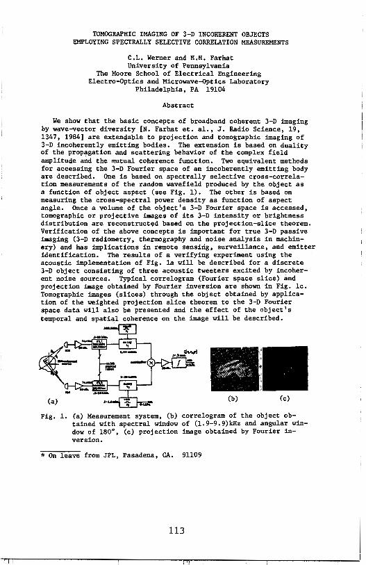
TOMOGRAPHIC IMAGING OF 3-D INCOHERENT OBJECTS EMPLOYING SPECTRALLY SELECTIVE CORRELATION MEASUREMENTS
C.L. Werner and N.H. Farhat University of Pennsylvania
The Moore School of Electrical Engineering Electro-Optics and Microwave-Optics Laboratory
Philadelphia, PA 19104
Abstract
We show that the basic concepts of broadband coherent 3-D imaging by wave-vector diversity [N. Farhat et. al., J. Radio Science, 19, 1347, 1984] are extendable to projection and tomographic imaging of 3-D incoherently emitting bodies. The extension is based on duality of the propagation and scattering behavior of the complex field amplitude and the mutual coherence function. Two equivalent methods for accessing the 3-D Fourier space of an incoherently emitting body are described. One is based on spectrally selective cross-correlation measurements of the random wavefield produced by the object as a function of object aspect (see Fig. 1). The other is based on measuring the cross-spectral power density as function of aspect angle. Once a volume of the object's 3-D Fourier space is accessed, tomographic or projective images of its 3-D intensity or brightness distribution are reconstructed based on the projection-slice theorem. Verification of the above concepts is important for true 3-D passive imaging (3-D radiometry, thermography and noise analysis in machinery) and has implications in remote sensing, surveillance, and emitter identification. The results of a verifying experiment using the acoustic implementation of Fig. la will be described for a discrete 3-D object consisting of three acoustic tweeters excited by incoherent noise sources. Typical correlogram (Fourier space slice) and projection image obtained by Fourier inversion are shown in Fig. le. Tomographic images (slices) through the object obtained by application of the weighted projection slice theorem to the 3-D Fourier space data will also be presented and the effect of the object's temporal and spatial coherence on the image will be described.
(a) (b} (c)
Fig. 1. (a) Measurement system, (b) correlogram of the object obtained with spectral window of (l.9-9.9)kHz and angular window of 180°, (c) projection image obtained by Fourier inversion.
* On leave from JPL, Pasadena, CA. 91109
113

A SURVEY OF IMAGE-EMBEDDED PASSIVE BEAMFDRMINB SOURCES FDR A RADIO CAMERA
J. Halat and B.D. Stainbarg Vallay Forga R .. aarch Cantar
Th• Moor• School of Elactrical Engin1111ring Univarsity of Pannsylvania
Philadalphia, PA 19104
An array that affords no accurata a priori alamant position information, as is th• ca•• for a radio camara in ganeral, damands soma form of adaptiva processing in ordar to function as a diffraction-limited imaging systam. Adaptiv• baamforming is a technique that axploits th• wall behaved amplituda and phasa propartias of a singl• point targat or sourca.
Echoes from the obJact fiald which exhibit radiation proparties similar to thosa of a point source can ba usad as baamforming sources. A survey has baan parformad on th• availability and datectability of passiva baamforming sourcas ambaddad in th• objact field of a radio camara system. Industrial, rasidential and undavalopad scan•• providad th• data for the survey.
A variance measure was applied to the echo amplitude data of the random array for beamformar detaction and a corralation measura of image quality was included to analytically define acceptable beamforming sources relative to known standard beamformars.
Betwaen 2.7X and 16.9X of th• range bins studied, depending on the scene type, behave as good baamforming sourcas. Of th•••, 1.BX to ~.BX ar• datected by the varianc• tast. Sinca radar systems typically oparate with 1mmm rang• bins, an abundance of detectable scattarars capable of cohering th• array is available.
114
PHILA. NORTH B-10-SCATTERING II
Chairman: L.N. Medgyesi-Mitschang TUESDAY-PM
Page 1:30 CHAIRMAN'S REMARKS 1:40 Scattering From a Corrugated Resistive Sheet
R.C. Hall and R. Mittra, University of Illinois ................. 116 2:00 Wave Scattering by a Sinusoidal Surface: A Variational Approach
E. P. Gray and J. F. Bird, The Johns Hopkins University, Applied, Physics Lab ........................................ 117
2:20 Scattering Characteristics of a Corrugated Conducting Cylinder T.C.K. Rao, University of Lowell. ............................ 118
2:40 Hybrid Solutions for Scattering from Bodies With Surface Discontinuities D.S. Wang, McDonnell Douglas Research Laboratories ......... 119
3:00 COFFEE BREAK 3:20 The Scattering From the Ogive Revisited
A. K. Dominek and L. Peters, Jr., The Ohio State University .... 120
3:40 Formulation and Numerical Solution for Scattering and Radiation by Patch Models ol Discrete Bodies of Revolution D.R. Wilton and R.M. Sharpe, University of Houston .......... 121
4:00 Scattering From a Slit Cylinder Enclosing An Off-Set Impedance Cylinder R.W. Ziolkowski and R.F. Schmucker, Lawrence Livermore National Laboratory ......................................... 122
4:20 Numerical Aspects ol the Evaluation of Hankel Functions ol Complex Order and Argument Arising in Scattering and Diffraction Theory R.A. Whitaker and L.W. Pearson, McDonnell Douglas .......... 123
4:40 Natural Frequencies ol Dielectric Coated Wires M.C. Lin and Y.W. Kiang, National Taiwan University .......... 124
115
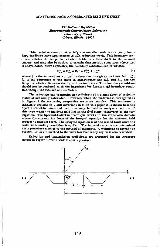
SCATIERING FROM A CORRUGATED RESISTIVE SHEET
RC. Hall and Raj Mittra B.ectronuignetic Cammunia,tion Laboralary
UniW!rsity of llJinois Urbana, llJinois 61801
Thin resistive sheets that satisfy the so-called resistive or jump boundary condition have applications in RCS reduction work. This boundary condition relates the tangential electric fields on a thin sheet to the induced current and may also be applied to certain thin metalic structures where loss is unavoidable. More explicitly, the boundary condition can be written
(1)
where J is the induced current on the sheet due to a given incident field E,~n;, Ro is the resistance of the sheet in ohms/square and E,!11 and E;;n are the tangental electric fields on the top and bottom faces. This boundary condition should not be confused with the impedance (or Leontovich) boundary condition though the two are not unrelated.
The reflection and transmission coefficients of a planar sheet of resistive material are easily calculated. However, when the material is corrugated as in Figure 1 the scattering properties are more complex. This structure is infinitely periodic in y and invariant in x. In this paper it is shown how the Spectral-Galekin numerical technique may be used to analyze structures of this type when the incident field lies in the i-z plane, transverse to the corrugation. The Spectral-Galerkin technique works in the transform domain where the convolution form of the integral equation for the scattered field reduces to product form. The integral equation is of the second kind when the resistive boundary condition is applied. The induced currents are determined via a procedure similar to the method of moments. A technique to extend the Spectral-Galerkin method to the very low frequency region is also described.
Reflection and transmission coefficients are presented for the structure shown in Figure 1 over a wide frequency range.
0
• • • •
116
WAVE SCATTERING BY A SINUSOIDAL SURFACE: A VARIATIONAL APPROACH
Ernest P. Gray and Joseph F. Bird Applied Physics Laboratory
The Johns Hopkins University Johns Hopkins Road
Laurel, Maryland 20707
We have used the Schwinger variational method to calculate the field wsc scattered by a perfectly conducting sinusoidal surface (whose corrugations run along.t~e y-direction) when irradiated by an incident plane wave w1n (propagating in the x-y plane of incidence). The theory of diffraction by periodic surfaces goes back to Rayleigh (1907) and has a rich history. The only previous bona fide variational approach, however, appears in an unpublished report by Lippmann, who used plane-wave trial functions in a Schwinger-type variational principle but did not carry the variational solutions to completion.
The main thrust of the present work is to experiment with trial function selection and to judge the variational results by a numerical comparison with known exact solutions. The most significant contribution we have made here is the recognition that the only a priori requirement for a trial function is that it satisfy the boundary conditions of the problems on the periodic scattering surface ~(x); its behavior off that surface is of no importance. We have implemented that requirement for the Dirichlet problem by expressing the scattered
1trial field in the
boundary-Born form, wSC(x,z) = winc(x,z) - ~ nc(x,~(x))f(x,z), where f(x,z) must be periodic in x and satisfy the constraint f(x,~(x)) = 1, but is otherwise totally arbitrary. We have adopted a particularly simple form for f, f(x,z) = g(z-~(x)), with g(O) = 1 (an analog of which has previously yielded very accurate variational results for circular cylinder scattering), and have evaluated it variationally, using ~(x) = h sinKx. Our method consists in expanding wsc in a Rayleigh expansion and expressing the expansion coefficients in a variationally invariant ratio of surface integrals involving the trial function. The two single integrals in the numerator of that ratio are relatively simple to evaluate. The demoninator, however, a double integral, has resisted all attempts at expressing it in closed form. We have been able to transform it into a double infinite sum of contour integrals whose integrands contain products of two Bessel functions.
Certain limits agree with the exact result. Thus, our variational method is correct in the flat-plane limit (h+O), the long wavelength limit (k+O), the short wavelength limit (k ..... ), and Rayleigh's grating limit (K+O). For other values of these parameters, we have evaluated the variational solution numerically, and compare it with exact results.
117

SCATTERING CHARACTERISTICS OF A CORRUGATED CONDUCTING CYLINDER
T.C.K. Rao Electrical Engineering Department, University of Lowell
Lowell, Massachusetts 01854
Abstract
In many applications in radar, it has long been recognized that the introduction of small corrugations on the surface of a conducting cylinder has some beneficial effects in minimizing or maximizing the backscattering crosssection from the cylinder and is considered as an alternative to dielectric. coating. Under the assumption that the guide wavelength is much larger than the corrugation constant D1 + D2 (D1 = spacing between the discs, D2 = thickness of the disc), Piefke obtained the solution of the wave equation by considering the inter-disc region as a quasi-homogeneous but anisotropic medium whose dielectric constant and permeability are tensor quantities (G. Piefke, IRE Trans. Ant. and Propagation, Sl83-Sl90, Dec. 1959). The scattering characteristics of such a disc loaded Sommerfeld line are investigated when a plane wave is incident on it. In particular, the backscattering crosssection and its variation with the physicaY parameters of the structure are discussed. The surface impedance concept is critically examined and compared with the results obtained from a numerical solution.
118
HYBRID SOLUTIONS FOR SCATTERING FROM BODIES WITH SURFACE DISCONTINUITIES
D.-s. Wang McDonnell Douglas Research Laboratories
P.O. Box 516 St. Louis, Missouri 63166
To properly account for scattering effects resulting from surface discontinuities, an extension of the recently developed hybrid method (L. N. Medgyesi-Mitschang and D.-s. Wang, IEEE Antennas Propagat., Vol. AP-31, No. 4, 570, 1983 and Vol. AP-32, No. 7, 717, 1984) is presented for electromagnetic scattering from electrically large, perfectly conducting and coated bodies. This extension incorporates two features: (a) a mixed boundary condition and (b) a correction to the physical optics (PO) Ansatz. The mixed boundary condition in the integral equation formulation combines the exact boundary conditions for areas near surface discontinuities and the impedance boundary condition (IBC) for the remaining smooth surface. This formulation is then solved using the method of moments (MM) technique with Ansatzes for the surface currents. The correction to the PO Ansatz is similar to the nonuniform current component explicated in the physical theory of diffraction (P. Ia. Ufimtsev, Soviet Physics - Tech. Physics, Vol. 27, No. 8, 1708, 1957). This correction yields greater accuracy than the previous formulation.
The present formulation includes not only higher-order scattering effects resulting from surface discontinuities, but also effects caused by coated surfaces having sharply changing curvatures, such as tips and edges. The formulation preserves the computational advantages of the IBC formulation, substantially reducing the number of unknowns. Representative scattering calculations are performed for axially symmetric bodies to verify the efficacy of the formulation. The results are compared with exact solutions based on the MM technique using exact boundary conditions and with available experimental data for large scatterers.
119
THE SCATTERING FROM THE OGIVE REVISITED
A. K. Dominek and L. Peters, Jr. ElectroScience Laboratory
Department of Electrical Engineering The Ohio State University
1320 Kinnear Road Columbus, Ohio 43212
The scattered fields of an ogive are revisited from a high resolution radar viewpoint. This particular target has been studied from a number of viewpoints, each yielding some improvement both in the analysis and in the understanding of the scattering mechanisms. First there was the physical optics solution which, of course, was seriously in error. Later the traveling wave concept gave reasonable results for the nonspecular return but contributed little to the understanding of the physical scattering mechanisms. Then a modified form of the creeping wave analysis gave better results in the near endfire region, but failed to give adequate performance when the observation point was not in a plane tangent to the ogive surface.
Using both computed results from a body of revolution moment method solution and experimental results in conjunction with high resolution scattering techniques, all of the scattering mechanisms on this shape can be evaluated. The results show that there is the usual creeping wave-tip-creeping wave term for near axial incidence. As the incidence angle increases, this term no longer exists. Here, the dominant term is the direct diffraction from the rear tip with smaller diffraction contributions from the front tip and the tipcreeping wave-tip mechanisms.
We shall present data on the angle of incidence and the frequency dependence of each mechanism as obtained from this high resolution process.
120
FORMULATION AND NUMERICAL SOLUTION FOR SCATTERING AND RADIATION BY PATCH
MODELS OF DISCRETE BODIES OF REVOLUTION
Donald R. Wilton and Robert M. Sharpe University of Houston, Houston, TX 77004
It is well known that geometrical symmetries present in a scatterer or radiator can often be exploited to reduce the computational effort involved in determining the induced current in moment method solutions of such problems. The procedure essentially requires the expansion of both the current and the excitation into symmetrical components and makes use of the orthogonality between the components to reduce the moment matrix to block diagonal form. Solution of the linear system can then be obtained on a block-by-block ha.sis, thus reducing both solution time and matrix storage requirements. Occasionally, the desired excitation happens to be one of the symmetrical components, in which case only a single block needs to be solved.
In a recent upgrading of capabilities of a surface patch code utilizing triangular patches, both electric and magnetic ground planes (reflection) symmetries in up to three mutually perpendicular planes were treated. In this paper, we examine a common type of rotational symmetry in which the geometrical surface may be rotated about an axis through an angle of 2,r / N into coincidence with itself. We use the term discrete body of revolution (DBOR) to describe such a surface, which, for N sufficiently large, can be used to model a continuous body of revolution (BOR). For a BOR, the symmetrical components are the Fourier components of the azimuthal field or current variation; for a DBOR, they are the discrete Fourier transform (DFT) components of these quantities at corresponding symmetrical positions. The composition of the block-diagonal form of the moment matrix can be shown to reduce to the computation of the DFT of selected elements from columns of the original moment matrix. For large N, this may be efficiently computed via the FFT. The inverse DFT of the symmetrical components of the surface current is required to finally obtain the actual current at a point on the object.
It is emphasized that no approximations are introduced in making use of DBOR symmetry and that the analysis can also be effectively used when only a portion of the structure is a DBOR. Furthermore, all the advantages of subsectional modeling are retained. In particular, it appears that the modeling of BOR's with unsymmetrical objects such as fins or wires attached is simplified since one does not require ha.sis functions which provide a transition between the BOR's entire domain and the attached object's subsectional basis functions. Indeed, it appears that there may be generally little advantage to using BOR analysis over DBOR analysis.
121

SCATTERING FROM A SLIT CYLINDER ENCLOSING AN OFF-SET IMPEDANCE CYLINDER
Richard W. Ziolkowski and Ronald F. Sctvnucker Lawrence Livermore National Laboratory
Engineering Research Division P.O. Box 5504, L-156
Livermore, CA 94550
Canonical electromagnetic aperture coupl Ing problems are important from several points of view. They provide a basic understanding of the coupling process which can be extrapolated to more general geometries. Moreover, they provide fundamental benchmarks for general purpose scattering codes.
The generalized dual series solution to the coupling of an H-polarized plane wave to a perfectly conducting infinite cylinder with an infinite axial slot enclosing an off-set interior impedance cylinder has been constructed by Ziolkowski and Schmucker [Boulder USRI Meeting, Jan. 1986]. This is a very important canonical problem because it allows one to study the effects of the location and size of an interior object on the aperture coupling. ~ one might expect, the off-set interior cylinder breaks the symmetry of the configuration and leads to new effects.
Results will be presented for the case where the interior object is a perfectly conducting wire. Frequency scans of the bistatic cross-section will be given for various locations and radii of the interior wire as well as for different angles of incidence and aperture sizes. These results are dominated by resonance features whose characteristics reflect the variations in those parameters. Plots of the fields, tot'al currents on the slit and interior cylinders, and currents on the inside and the outside of the slit cylinder will also be given at frequencies corresponding to the locations of those resonance features.
• This work was performed by the Lawrence Livermore National Laboratory under the auspices of the U.S. Department of Energy under contract W-7405-ENG-48.
122
NUMERICAL ASPECTS OF THE EVALUATION OF HANKEL FUNCTIONS OF COMPLEX ORDER AND ARGUMENT ARISING
IN SCATTERING AND DIFFRACTION THEORY
Rick A. Whitaker McDonnell Douglas Aerospace Information Services
L. Wilson Pearson McDonnell Douglas Research Laboratories
P. o. Box 516 Saint Louis, MO 63166
When Green's functions for wave equations are represented by the so-called angular propagation representation (or equivalently when the Watson transform is performed on an angularly periodic expansion), the need arises to compute solutions of Bessel's differential equation for complex order, and, potentially, for complex argument. Three-term recursion algorithms are viable for this computation provided the argument and order are not too large in magnitude (say 10). When the magnitude of the order parameter is larger, the functions are exponentially dependent on order so that recursive techniques either become costly or fail entirely because of the influence of limited machine precision. There are three well-documented asymptotic expansions available for solutions to Bessel's equation: the Debye expansions, which are described in detail by Watson (Theory of Bessel Functions, 1966); the transition region expansions due to Olver (Proc. Camb. Phil. Soc., 48, 414, 1952); and the uniform expansions (see F.W.J. Olver,-Xsymptotics and Special Functions, 1974). The Debye expansions are complicated to apply because the representations change according to the relative location of order and argument in the complex plane and because they fail entirely at the turning point, where argument and order are equal. Olver•s expansions are complicated because they depend on the computation of Airy functions of complex argument. The implementation of the uniform expansion is more complicated than the transition region expansion principally because of the polynomial series arising in the expansion.
This presentation reviews the computational issues associated with the approaches enumerated above. The non-trivial problem of validating the calculations of the functions is addressed through numerical comparison of independent methods and through testing the satisfaction of recursion relations that are independent of any algorithmic recursion that is applied. Some observations are made about error estimation and the a priori specification of error tolerance.
123

NATURAL FREQUENCIES OF DIELECTRIC COATED WIRES
ABSTRACT
Min-Chin Lin and Yean-Woei Kiang Department of Electrical Engineering
National Taiwan University Taipei, Taiwan, R.O.C.
The natural frequencies of dielectric coated thin wires are numerically computed using a moment method of reaction formulation. Considerable variations of natural frequencies are found under the changes of dielectric constant of the coating. The effects of partial coating are also examined.
INTRODUCTION
Several methods for solving transient scattering problems have been developed during the past decade [1]. One important approach is the singularity expansion method (SEM) based on the analysis of the response in the complex frequency S -domain. The fundamental quantities in the SEM method are natural frequencies at which the natural resonant modes exist in the absence of external excitation. It has been shown that the complex resonant frequencies of the scatterer are determined only by the geometry and composition. This essential property of the natural frequencies may serve for target discrimination and indeed various algorithms have been proposed [2],[3]. Therefore, the study of the effects of dielectric coating on the natural frequencies may be important to the radar target discrimination.
In this paper we investigate the variations of natural frequencies due to dielectric coating by an efficient moment method introduced by Richmond and Newman [4]. The dielectric coated thin wires are examined with the restriction that the coating layer is not too thick.
124

SALON 3/4 B-11-TRANSIENTS AND RESONANCES
Chairman: K.M. Chen TUESDAY-PM
Page 1:30 CHAIRMAN'S REMARKS 1:40 Dielectric Resonances in Printed Microwave Complementary
Dipole Pairs Using High-Permittivity Substrates K.G. Schroeder, American Electronics Labs Inc ................ 126
2:00 Extraction of the Natural Frequencies of a Complex Radar Target from Measurements of its Response W.M. Sun, E.J. Rothwell, K.M. Chen and D.P. Nyquist, Michigan State University ...................... 127
2:20 Extraction of Target Natural Frequencies From Measured Transient Surface Charge and Current Waveforms N. Gharsallah, K.M. Chen, E.J. Rothwell and D.P. Nyquist, Michigan State University ................................... 128
2:40 Asymptotic Model-Based Transient Electromagnetic Identification D.G. Dudley and R.R. Weyker, University of Arizona ........... 129
3:00 COFFEE BREAK 3:20 The Extraction of Singularity Expansion Parameters
Using PADE Approximants D.C. Power, Raytheon Co .................................... 130
3:40 Generation of Impulse Waveforms with Large Energy Content T. K. Sarkar, Syracuse University ................ ., ............ 131
4:00 K-Pulse Estimation From the Impulse Response of a Target F. Fok, D.L. Moffatt and N. Wang, The Ohio State University ............................................ 132
4:20 Extraction of Target Impulse Response by Deconvolution of Real-Time Measured Data M. Blischke, E. Rothwell, B. Drachman, D.P Nyquist and K.M. Chen, Michigan State University .................... 133
4:40 Expansion of K-Pulse in Terms of Legendre Polynomials for an Arbitrary Target G. Turhan and D.L. Moffatt, The Ohio State University ........ 134
125

DIELECTRIC RESONANCES IN PRINTED MICROWAVE COMPLEMENTARY DIPOLE PAIRS USING HIGH-PERMITTIVITY SUBSTRATES
K. G. Schroeder American Electronic Laboratories, Inc. Lansdale, Pa., 19446
A previous analysis has shown that microstrip radiators covered with dielectric material will experience a change in resonant frequency and a lower resonant resistance. (A.J.M. Soares, et al; IEEE Transactions AP-32, No. 11, Novem-ber 1984, pp. 1149-1154.) In this paper, the effect on effective element spacing as well as effective element impedance will be investigated experimentally for the case of endfire complementary pairs of flat sheet dipoles printed on a dielectric substrate of high permittivity. While the same effect on resonant length, effective spacing and patterns is experienced, the impedance can be matched similar to free-space pair, because the external matching mechanism is independent of the substrate permittivity.
126

EXTRACTION OF THE NATURAL FEQUENCIES OF A COMPLEX RADAR TARGET FROM MEASUREMENTS OF ITS RESPONSE
W.M. Sun, E.J. Rothwell, K.M. Chen, D.P. Nyquist Department of Electrical Engineering and Systems Science Michigan State University, East Lansing, Michigan 48824
The use of natural resonances in various radar target identification schemes has prompted renewed investigation into methods for the extraction of natural resonance frequencies from measured responses. Prony's method has proven inadequate due to its sensitivity to noise and to the number of modes assumed present in the measured response.
Three methods which are much less sensitive to noise level and to modal content have been developed: the continuation method, a nonlinear least-squares technique, and two E-pulse related schemes. Each of these methods has been quite successful in extracting complex frequencies from numerical data under a variety of circumstances. Most promising, these techniques have also been successful in extracting natural frequencies from complex radar targets, including scale aircraft models. Numerous results will be presented.
127

EXTRACTION OF TARGET NATURAL FREQUENCIES FROM MEASURED TRANSIENT SURFACE CHARGE AND CURRENT WAVEFORMS
N. Gharsallah, E.J. Rothwell, D.P. Nyquist and K.M. Chen Department of Electrical Engineering and Systems Science
Michigan State University East Lansing, Michigan 48824
The natural resonant frequencies of a radar target provide a unique characterization of the transient electromagnetic response of that target; they consequently provide a basis for target identification and discrimination techniques. Those frequencies are commonly extracted from late-time, far-zone, time-domain scattered field measurements. Natural frequency extraction is critically dependent upon the signal-to-noise ratio of measured responses. Target natural resonance frequencies are shared by both its scattered field and its induced surface charge and current distributions. It is therefore suggested, for laboratory scale-model experiments, that the scattered field method be augmented by mode extraction from measured transient near-field surface charge and current waveforms.
A short monopole probe perpendicular to the target surface responds to the normal component of E-field there, which is proportional to the local surface charge density. Similarly, a semicircular loop probe oriented perpendicular to the target surface responds to the tangential component of H-field normal to the loop, which is proportional to the local surface current density. Both of these probes behave as ideal differentiators when electrically small. They offer two main advantages: 1) their responses are relatively large, providing improved signal-to-noise ratio and 2) the early-time periods of charge and current to which they respond is relatively short, permitting natural mode extraction from earlier measured responses of relatively large amplitude. Probe responses tons-pulse target illumination are measured using a ps-risetime sampling and waveform processing oscilloscope.
Natural frequencies are subsequently determined by fitting the measured late-time transient surface charge or current waveforms to a natural-resonance-mode SEM representation of those responses. Extraction is accomplished using algorithms based upon the continuation and other methods, subsequent to use of the FFT to provide an initial estimate of frequency content in the measured data.
Adequacy of the SEM representation and the experimental measurement and mode extraction protocols is first tested for thin-wire cylinder and loop targets (natural frequencies known with confidence from analytical computations), where aspect independence of the resulting natural frequencies is confirmed. Natural frequencies of complex aircraft models are subsequently measured using optimally-located surface probes.
128

Asymptotic Model-Based
Transient Electromagnetic Identification
Donald G. Dudley Robert R. Weyker
Electromagnetics Laboratory Department of Electrical and Computer Engineering
University of Arizona Tucson, AZ 85721, USA
To date, methods in transient electromagnetic identification have been based primarily on a pole-zero (PZ) difference equation model. The inputoutput data associated with the electromagnetic scattering process is entered into the difference equation whoee coefficients are then adjusted, by some strategy, to make the model close to the process in some well-defined mathematical sense. The solution to the difference equation is a complex exponential series whose parameters describe a sequence of resonances associated with the difference equation input-output data. In some cases, it has been possible to relate these data resonances to the body resonances of the electromagnetic scattering object. There have been several cogent criticisms of this method. First, even for perfectly conducting scatterers, the complex exponential series is an incomplete description of the scattered field and must be supplemented by the inverse transform of an entire function of frequency. This entire function is incorrectly modeled by the difference equation model. This difficulty is unfortunate since the entire function often represents the dominant contribution to the transient signal. Second, for time-limited data, the. identification of the complex resonances is not unique. Therefore, there are no guarantees that the resonances of the data can be related to the body resonances of the scattering object.
It has been shown that for a perfectly conducting scatterer, the entire function contribution is time-limited in the early-time transient response. In this paper, we use this fact to produce an early-time asymptotic identification method. The method is based on the asymptotic expansion of the electromagnetic fields in inverse powers of iw. This expansion leads to an Jv'h order moving average (MA) difference equation model whose output is the Iv'" backward difference of the scattering process output. We test the method with synthetic data associated with acoustic scattering from a hard sphere. We compare the robustness of the method with results from the more usual PZ model and suggest methods to incorporate the better features of both PZ and MA modeling.
129

lliE EXTRACTION OF SINGULARITY EXPANSION PARAMETERS USING PADE APPROXIMANTS
Dona 1 d C. Power Raytheon Company
Missile Systems Division Hartwe 11 Road
Bedford, Ma 01730
The extraction of the poles in the Singularity Expansion Method (SEM) using Prony's algorithm is shown to be equivalent to the formation of a particular Pade approximant to the z-transform of the transient response. Although the equivalence of Prony's method to the Pade approximation technique is well known, (L. Weiss and R.N. McDonough, SIAM Review, Vol. 3, 1963), the consideration of the SEM problem from this point of view provides greater understanding and insight. In particular, it is shown that consideration of the singularities of the Pade approximants in the z-plane enables the extraction of information which is difficult to obtain or is undetectable from the standard approach.
130

GENERATION or IMPULSIVE WAVEFORMS WITH LARGE ENERGY CONTENT
Tapan K. Sarkar Department of Electrical Engineering
Syracuse University Syracuse; New York 13244-1240
(315) 423 - 3775
ABSTRACT: It is highly desirable to obtain impulsive waveforms with a large energy content.This
is because for a linear system, an impulse response of the object uniquely characterizes the object just like a finger print identification. This presentation will explore means of generating electrical pulses of about kilovolts in amplitude and about three hundred picoseconds pulse duration. One of the possible applicaions of such a device would be to provide a laboratory tool for the experimental determination of electromagnetic resonances of objects of interest. A second application would in the development of a time domain radar.
131

K-PULSE ESTIMATION FROM THE IMPULSE RESPONSE OF A TARGET
Fredric Fok, David L. Moffatt and Nan Wang The Ohio State University ElectroSclence Laboratory
Department of Electrlcal Engineering Columbus Ohio 43212
A slmple and general method Is described to estimate the K-pulse of a target from Its synthesized or exact Impulse response. The approach Is based on minimization of energy content outside the K-pulse response duration. The method Is slmple because It only deals with Dirac delta functions In Integrals. It Is also general because the method only manipulates samples of a continuous function, a normal computer operation. The method does not require a priori Information on the target poles. Results obtained from both exact and synthesized data, show excel lent convergence.for the K-pulses. Furthermore, dominant poles of the target can be extracted from the approximated K-pulse. The pole-extraction method Is also discussed In association with some of the results.
132

EXTRACTION OF TARGET IMPULSE RESPONSE BY DECONVOLUTION OF REAL-TIME MEASURED DATA
M. Blischke, E. Rothwell, B. Drachman*, D.P. Nyquist and K.M. Che, Dept. of Elect. Engr. & Sys. Science, Dept. of Mathematics*
Michigan State University, E. Lansing, Michigan 48824
A method of extracting impulse responses of radar targets is being investigated for use as a means of target di·scrimination in radar.
When a target is illuminated with an electromagnetic impulse, it oscillates electrically at certain natural frequencies characteristic of the target. By measuring these natural frequencies and comparing them various targets can be discriminated. With an ideal TEM impulse and a short monopole acting as an ideal differentiator, the impulse response can be found by integrating the measured response. To improve the signal to noise ratio it is desired to use a long monopole which, however, would cease to approximate an ideal differentiator. A band limited impulse and the frequency characteristics of the transmitting system also serve to distort the measured response from the ideal.
In order to use a large receiving antenna effectively, a method of removing the response characteristics of all systems involved but the target is needed. A measurement of the transmitted signal directly by the receiving antenna without a target present contains all distorting response characteristics that are to be removed from the measured target response and serves as a base response. Deconvolving the base response from the target response leaves the pure impulse response of the target as desired.
Deconvolution is carried out with real time measured data by the use of matrices. The matrix equation arrived at is E·H = R where Eis a matrix fashioned from the base response, Risa vector containing the response from the target and His a vector representing the impulse response for which we are solving. This equation is illconditioned, and directly solving it for data containing noise yields results which, while mathematically correct, are physically nonsense. The solution is instead found by altering the matrix equation slightly through the use of a parameter, p, to achieve another matrix equation
t t E ·E·H + p·H = E •R
which is approximately the original equation but which is significantly less ill-conditioned.
Implementation of this method will be discussed along with application to real measured data and the results obtained for a target whose theoretical response is known.
133
EXPANSION OF K-PULSE IN TERMS OF LEGENDRE POLYNOMIALS FOR AN ARBITRARY TARGET 1
Gonul TURBAN and David L. MOFFATT
Tht: Ohio State University ElectroScience Lab Department of Electrical Engineering
Columbus, Ohio 43212
The K-Pulse is an excitation waveform of minimal finite duration producing a time-limited response. The Laplace transform of the K-Pulse should be an entire function having the distribution of zeroes which coincides with the distribution of poles of the target under consideration.
In this paper, we will discUII a special inversion technique to approximate the K-Pulse for an arbitrary target. Since the K-Pulse is a timelimited function, this permits one to use an expansion in terms of Legendre polynomials whitjl form a complete, orthogonal set of basis functions over a bounded time interval. The weighting coefficients of this expansion can be obtained using the pole distribution of the target only.
There is an indication from the behaviour of the expansi9n coefficients that a delta function type of singularity may occur in the K-Pulse for some targets. In such a cue, the position and the weighting for the impulse term need to be estimated before proceeding to find the coefficients of the Legendre Series for the regular part of the K-Pulse.A possible approach to this problem is proposed.
Applications of the proposed method to different target geometries will be presented and the numerical difficulties encountered will be discU11ed.
'Work npponed in pan by Department of Na'V)', Joint Service Elecuonica Program Contract N00014-78-C-0049with the Ohio State Univeniq, R.earch Foundation.
134
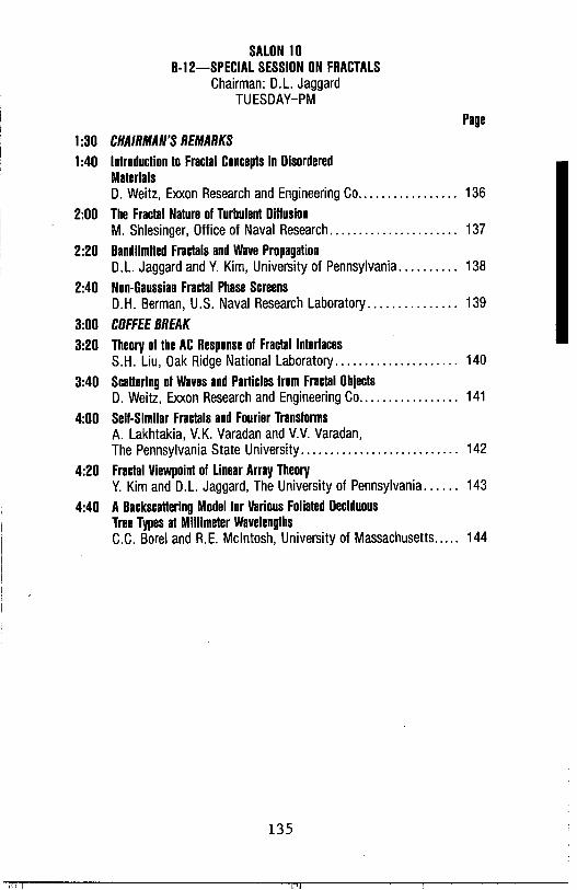
SALON 10 B-12-SPECIAL SESSION ON FRACTALS
Chairman: D.L. Jaggard TUESDAY-PM
Page
1:30 CHAIRMAN'S REMARKS 1:40 Introduction to Fractal Concepts in Disordered
Materials D. Weitz, Exxon Research and Engineering Co ................. 136
2:00 The Fractal Nature of Turbulent Diffusion M. Shlesinger, Office of Naval Research ...................... 137
2:20 Bandlimited Fractals and Wave Propagation D.L. Jaggard and Y. Kim, University of Pennsylvania .......... 138
2:40 Non-Gaussian Fractal Phase Screens D.H. Berman, U.S. Naval Research Laboratory ............... 139
3:00 COFFEE BREAK 3:20 Theory of the AC Response of Fractal Interfaces
S.H. Liu, Oak Ridge National Laboratory ..................... 140
3:40 Scattering of Waves and Particles from Fractal Objects D. Weitz, Exxon Research and Engineering Co ................. 141
4:00 Self-Similar Fractals and Fourier Transforms A. Lakhtakia, V.K. Varadan and V.V. Varadan, The Pennsylvania State University ........................... 142
4:20 Fractal Viewpoint of Linear Array Theory Y. Kim and D.L. Jaggard, The University of Pennsylvania ...... 143
4:40 A Backscattering Model for Various Foliated Deciduous Tree Types at Millimeter Wavelengths C.C. Borel and R.E. McIntosh, University of Massachusetts ..... 144
135
AN INTRODUCTION TO FRACTAL CONCEPTS IN DISORDERED MATERIALS
D. A. Weitz Exxon Research and Engineering Co. Rt. 22 East, Annandale, NJ 08801
The first step in a quantitative account of the physical properties and behavior of any material is necessarily a quantitative description of its structure. Nevertheless, there exists in nature a large and commonly encountered class of materials whose structure is so highly disordered that it has, until recently, defied quantitative characterization. However, the introduction of the concepts of fractals has dramatically changed this, making the structure, and physical properties, of a large subset of disordered materials accessable to quantitative characterization. In this talk, we will introduce the basic concepts of fractal geometry, and demonstrate how it has been successfully applied to describe the structure of a variety of materials. The emphasis will be on developing a physical picture of fractal structures, and several examples will be discussed in more detail to illustrate both their structure and physical properties. In addition, a brief description of some growth processes which can lead to fractal structures will be presented.
The key property which distinguishes fractal structures is their invariance under a change in length scale. Thus, if a fractal object were viewed under a microscope, it would have the same appearance for all scales of magnification. As a consequence, a fractal possesses no characteristic length scale, but rather has structural features on all length scales. This scale invariance is, in fact, a form of symmetry, and is called dilation symmetry. Of course, for any fractal material found in nature, scale invariance can exist only over a finite range of length scales, and thus the fractal behavior is bounded both above and below. Furthermore, all natural fractal materials are random and thus, their invariance under dilation is true in a statistical sense rather than an exact sense.
A fractal material can be characterized by the scaling of mass with length scale, t+-R f, where df is called the fractal dimension and is typically not an integer, and less than the dimension of space.·
One of the most appealing features of a fractal description of disordered materials is that the dimensions which characterize the structure have a clear geometric significance, making possible a visualization of their significance. This talk will demonstrate this with reference to specific examples of disordered materials.
136
THE FRACTAL NATURE OF TURBULENT DIFFUSION
Michael F. Shlesinger, Office of Naval Research, Physics Division, 800 North Quincy Street, Arlington, Virginia 22217-5000
We introduce a stochastic process, called a Levy Walk, which, describes random (but still correlated) motion in space and time in a scaling fashion. The process can be represented by either a generalized master equation or a random walk with nonlocal memory coupled in both space and time. We apply our correlated random walk model to the description of fluctuating fluid flow so that when Kolmogorov's -5/3 law for homogeneous turbulence determines the memory function, then Richardson's 4/3 law law of turbulent diffusion for a passive scalar follows. If, as suggested by Mandelbrot, turbulence is fractally homogeneous, then intermittency corrections to the -5/3 law follow in a natural fashion.
137
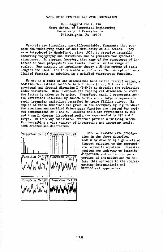
BANDLIMITED FRACTALS AND WAVE PROPAGATION
D.L. Jaggard and Y. Kim Moore School of Electrical Engineering
University of Pennsylvania Philadelphia, PA 19104
Fractals are irregular, non-differentiable, fragments that possess the tmderlying order of self similarity on all scales. They were introduced by Mandelbrot, circa 1977, to describe naturally occurring topography and structures and to generate new synthetic structures. It appears, however,.that many of the structures of interest in wave propagation are fractal over a limited range of scales. For example, in turbulence theory a finite number of scale lengths are used. For this reason we introduce the concept of bandlimited fractals as embodied in a modified Weierstrass ftmction.
We use as a model of one-dimensional bandlimited fractal medium, a modified Weierstrass ftmction with N tones (i.e., N lines in the spectrum) and fractal dimension D (l<D<2) to describe the refractive index variation. Here D exceeds the topological dimension Dr where the latter is taken to be tmity. Therefore, small D represents gentle variations described by smooth curves while large D represents rapid irregular variations described by space filling curves. Examples of these ftmctions are given in the accompanying figure where the spectrum and modified Weierstrass ftmction are plotted for various combinations of D and N. Ordered media are r~presented·by D~l and N. small whereas disordered media are represented by D$2 and N large. In this way bandlimited fractals provide a unifying scheme for describing a wide variety of interesting and important media, both ordered and disordered.
Here we examine wave propagation in the above described medium by developing a generalized Floquet solution to the appropriate Helmholtz equation. Investigations are underway to describe dispersion and reflection properties of the medium and to relate this approach to the corresponding deterministic and statistical approaches.
138
NON-GAUSSIAN FRACTAL PHASE SCREENS
David H. Berman U.S. Naval Researcli Laboratory
Washington, DC 20375-5000
Recent evidence indicates that single and two-point statistics of ocean bottom heights are non-Gaussian. In addition, the spectrum of ocean bottom heights, i.e. the Fourier transform of the heightheight correlation function, exhibits inverse power-law dependence on wave number. For these reasons, ocean bathymetry might be characterized as a non-Gaussian fractal. The fractal dimension appears to be less than 3/2 and the statistics of the bathymetry are adequately described by K-distributions. This paper investigates consequences of these facts for underwater acoustic scattering by examining the statistics of an acoustic field far behind a Kdistributed fractal phase screen. In the case of Gaussian phase screens it. is known that far from the screen, the scintillation index of the field saturates at its Rayleigh value of 1. In the case of K-distributed phase screens, the scintillation index again saturates to the Rayleigh value. However, for extremely nonGaussian. screens with fractal dimension D < 3/2, the rate of approach to the asymptotic limit is considerably slower than for Gaussian screens. In addition, in this last case the scintillation index approaches 1 from below rather than from above as in the Gaussian case. This means that signal detection might be easier than in the case of a Gaussian phase screen because intensity fluctuations are more constrained.
139

THEORY OF THE AC RESPONSE OF FRACTAL INTERFACES
S. H. Liu
Solid State Division, Oak Ridge National Laboratory Oak Ridge, TN 37830
ABSTRACT
The electrical properties of the interface between a metal electrode and an aqueous or solid electrolyte are important problems in electrochemistry and related technology because they affect the performance of electrochemical devices. In the classical theory an alternating current driven through the interface is expected to encounter an interfacial capacitance in series with the ohmic resistance in the electrolyte. The predicted frequency dependence of the impedance is very simple, i.e. the real part is independent of the frequency and the imaginary part is inversely proportional to the frequency, In reality, however, such an RC circuit does not give an adequate description of the ac response of the interface. It is often necessary to include a so-called constant-phaseangle (CPA) element whose impedance has the form Z « (jw)-?, where w is the angular frequency and the exponent n satisfies O < n < 1. In recent years it has been demonstrated by many authors that this unusual circuit element originates from the microscopic roughness of the interface. When the interface is made increasingly smooth, the exponent approaches unity. We propose to model the rough interface by fractals, and derive on the basis of a number of regular as well as random fractal models that n is related to the fractal dimension of the interface ds by n = 3 - ds, Experiments are under way to check how well this relation is obeyed by real interfaces.
Research sponsored by the Division of Materials Sciences, U. s. Department of Energy under contract DE-AC05-840R21400 with Martin Marietta Energy Systems, Inc.
140

SCATTERING OF WAVES AND PARTICLES FROM FRACTAL OBJECTS
D. A. Weitz Exxon Research and Engineering Co. Rt. 22 East, Annandale, NJ 08801
Through the use of of concepts fractals or scale invariance, it is now possible to quantitatively describe the structure and physical properties of a wide class of highly disordered materials. A fundamental property of fractal objects is the behavior of their density-density correlation function, g(r)-r-u where the co-dimension is a = d-df, with d the Euclidean dimension of space, and df the fractal dimension which directly characterizes the material. The form of the correlation function will be reflected directly in the coherent scattering of either waves or particles from a fractal, as the scattering function is simply the Fourier transform of the correlation function. Indeed, scattering techniques are a powerful way of actually measuring the structure of fractal objects. In this paper, we discuss in detail the scattering of light, X-rays and neutrons from a prototypic fractal object.
The samples used are aggregated aqueous gold colloids, whose highly disordered structures are very well characterized as fractals. Furthermore, while the colloids represent an easily controlled and well characterized example of kinetic growth, similar behavior is expected for a wide variety of other growth processes, and the insight gained from this study should be quite generally applicable. We study the scattering intensity as a function of the scattered wave vector, S(q), which represents a Fourier transform of the density-density correlations of the aggregate. The most detailed information comes from a small angle X-ray scattering experiment performed with synchrotron radiati~n, and extending over near~ t~ree decades in q, frol!lv 3 x 10- to - 8 x 10- A-. The data is interpreted with a model which includes the form factor of the individual spheres, the short range packing of the nearest neighbors and the long range fractal correlations of the aggregate.
The scattering of both neutrons and light correspond very closely to that of X-rays, although each of these probe a much smaller range in q. The scattering of light is complicated by the fact that the gold spheres possess an electronic plasma absorption resonance, which leads to a concomitant increase in the scattering intensity. We will discuss measurements of the q and frequency dependence of both the polarized and depolarized scattering as well as the frequency dependence of the absorption, and compare these to the results of a self-consistent calculation of the scattering including terms to the electric dipole order.
141

SELF-SIMILAR FRACTALS AND FOURIER TRANSFORMS
Akhlesh Lakhtakia, Vijay K. Varadan and Vasundara V. Varadan Laboratory for Electromagnetic and Acoustic Research
Department or Engineering Science and Mechanics The Pennsylvania State University Ul',"IVERSITYPARK,PA 16802
In recent years, Investigations into the geometry of matter have revealed fundamental discrepancies between Euclidean geometry and the i:eometry of naturally-occurring structures. Euclidean i:eometry Is characterized by Integral dimensions D: a line Is unidimensional (D = 1), a plane ls bldlmenslonal (D = 2), and so on. However, as Mandelbrot (Th Fractal Gtomttry of Nature, New York: Freeman, 1983) bas ari:ued successfully, a highly zlgzai: line tends to till up an area; hence, its dimension should be between 1 and 2 as opposed to its Euclidean dimension of unity. Arguments of like nature can be Invoked for objects of bli:ber Euclidean dimensions as well, and, as such, the concept or fractal, or non-integral, dimension d seems to be well-founded. Fractal structures are characterized by several properties, or which a more notable one ls their scal,-invarianc,. Strictly geometric fractals can be constructed which possess scale-invariance in the form of self-similarity, among the more notable ones being the Koch triad and the Sierpinski i:asket.
Since the procedure of taklni: the Fourier transform ls a linear process, it can be shown that the Fourier transforms of self-similar geometrical fractals are themselves self-similar fractals. Thus, such fractals appear to be or significance tor diverse E:\I problems, Including the synthesis of active/passive arrays and the design or SAW rllters, mlcrostrlpllne circuitry, etc.
Procedures for constructing self-similar arrays will be examined. A generalisation or the Sierpinski i:asket, named the Pascal-Sierpinski i:askets, will be Introduced here, and their Fourier transforms and scale-invariance Investigated, Dlrrractlon by a simple Sierpinski gasket screen and a Sierpinski carpet screen will be discussed to show the potential use or i:eometrlc fractals in array problems.
The Pascal-Sierpinski gasket of order 3
142
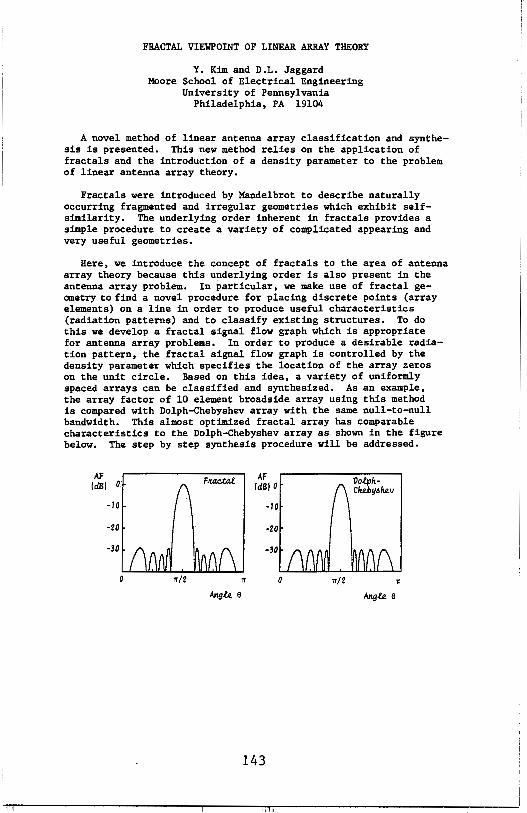
FRACTAL VIEWPOINT OF LINEAR ARRAY THEORY
Y. Kim and D.L. Jaggard Moore School of Electrical Engineering
University of Pennsylvania Philadelphia, PA 19104
A novel method of linear antenna array classification and synthesis is presented. This new method relies on the application of fractals and the introduction of a density parameter to the problem of linear antenna array theory.
Fractals were introduced by Mandelbrot to describe naturally occurring fragmented and irregular geometries which exhibit selfsimilarity. The underlying order inherent in fractals provides a simple procedure to create a variety of complicated appearing and very useful geometries.
Here, we introduce the concept of fractals to the area of antenna array theory because this underlying order is also present in the antenna array problem. In particular, we make use of fractal geanetry to find a novel procedure for placing discrete points (array elements) on a line in order to produce useful characteristics (radiation patterns) and to classify existing structures. To do this we develop a fractal signal flow graph which is appropriate for antenna array problems. In order to produce a desirable radiation pattern, the fractal signal flow graph is controlled by the density parameter which specifies the location of the array zeros on the unit circle. Based on this idea, a variety of uniformly spaced arrays can be classified and synthesized. As an example, the array factor of 10 element broadside array using this method is compared with Dolph-Chebyshev array with the same null-to-null bandwidth, This almost optimized fractal array has comparable characteristics to the Dolph-Chebyshev array as shown in the figure below. The step by step synthesis procedure will be addressed.
AF F"4Ctal. AF (dBi 0 (dBi 0
Do,f.ph-C he.byi> he.v
-10 -10
-20 -20
-30 -30
0 Tr/2 Tr 0 Tr/2 Tr
Angle e
143
A BACKSCATTERING MODEL FOR VARIOUS FOLIATED DECIDUOUS TREE TYPES AT MILLIMETER WAVELENGTHS
C.C. Borel, R.E. McIntosh Microwave Remote Sensing Laboratory
Departement of Electrical and Computer Engineering University of Massachusetts
Amherst, MA 01003, USA
This paper develops a model for foliated deciduous trees for frequencies above 35 GHz using geometrical optics. The leaf is modeled as a segment of a thin spherical shell of dielectric material, made of a mixture of water and solid material. The orientation of the leaves is determined using one out of five different probablity densities for the leaf inclination angle. The leaf diameter and the radius of curvature are other parameters considered in the model. The position of the leaves is computed by a fractal theory model for the structure of trees, which is able to generate many different tree types using different branching angles.
A computer simulation computes the normalized radar cross section (NRCS) for a small area of the tree viewed from an arbitrary point with ray tracing techniques. These NRCS-pixels form then a picture of the tree and indicate that the scattering intensity is also a function of the position. The NRCS computation takes shadowing and absorbtion into account.
144
PHILA. NORTH B-13-GUIDED WAVES Chairman: S.T. Peng WEDNESDAY-PM
Page
1:30 CHAIRMAN'S REMARKS 1:40 Cutoff Characteristics of First Higher-Order Mode
of Elliptical Fibers S.R. Rengarajan, California State University .................. 146
2:00 Application of the Scalar Wave-Fast Fourier Transform Technique to Weakly Guiding Dielectric Couplers, Horns, and Branches F. Manshadi, JPL; C.W. Yeh, University of California, LA ....... 147
2:20 Creeping Wave Propagation on Conducting Cylinders Coaled with Lossy Ferrite Material H. Kim and N. Wang, Ohio State University .................. 148
2:40 New Method for the Analysis of Surface Waves S.T. Peng, New York Institute of Technology; S.L. Wang, University of New Haven ......................... 149
3:00 COFFEE BREAK 3:20 Dispersion Analysis of Microslrip-Like Transmission Lines on
a Large Class of Anisotropic Substrates R. Marques and M. Homo, Facultad de Fisica, Sevilla, Spain .............................................. 150
3:40 Prediction of Laser Wavelength for Minimum Total Dispersion in Single-Mode Graded-Index Fibres A. Alphones and G.S. Sanyal, Indian Institute of Technology ... 151
4:00 Design Limitations on Finline Fillers and Matching Networks A.S. Omar and K. Schunemann, Technische Universitat Hamburg-Harburg ........................................... 152
4:20 Optical Time Division Multiplexing Device K.A. AI-Kateeb, A.M. Jassim and A.M. Khidir, University of Technology, Baghdad ........................... 153
145
CUTOFF CHARACTERISTICS OF FIRST HIGHER-ORDER MODE OF ELLIPTICAL FIBERS
Sembiam R. Rengarajan Department of Electrical and Computer Engineering
California State University, Northridge Northridge, CA 91330
Cutoff frequency characteristics of two-layer step index el I iptical fibers in the literature are reviewed. For the limiting case of unity eccentricity, modes and field distribution in elliptical fibers are shown to be different from those of a dielectric slab. However, a correspondence between the first higher order mode cutoff frequency between rectangular and el I iptical fibe'rs is presented. From mode correspondence and other physical considerations, confidence in the results of a
-previous publication (Rengarajan and Lewis, Electron Lett., vol. 16, no. 7, 1980) is established. The results of a recent paper (Saad, IEEE Trans, M.T.T., vol. MTT-33, no. 11, 1985) are shown to have I imitations.
146
APPLICATION OF THE SCALAR WAVE-FAST FOURIER TRANSFORM TECHNIQUE TO WEAKLY GUIDING DIELECTRIC COUPLERS,
HORNS, AND BRANCHES
F. Manshadi Jet Propulsion Laboratory, Pasadena, CA
C. W. Yeh University of California, Los Angeles, CA.
The Scalar Wave-Fast Fourier Transform Technique (SW-FFT) has been shown to be a powerful tool in solving the problem of wave propagation along weakly guiding optical waveguides (F. Manshadi, c.w. Yeh, Proceedings of 1985 North American Radio Science meeting, Vancouver, B.C. pp. 177). The technique is based on the solution of the scalar wave equation by the forward-marching fast fourier transform method and is applicable to dielectric waveguides of arbitrary shape and three dimensional refraction index variation. The solution yields the spatial configuration of the field and its power intensity along the guiding structure. A subsequent spectrum analysis performed on the power intensity provides the modal characteristics of the field such as the propagation constant and the relative amplitude of each mode (M.D. Feit, J.A. Fleck, Jr., appl. optics, 19, 1154-1164, 1980). This technique has been successfully applied to several simple optical waveguides such as, step-index circular fiber, graded index circular fiber, elliptical, triangular, and rectangular dielectric waveguides. The validity of these results were proved by comparing them with solutions obtained by other known exact and approximate methods.
In this paper, the SW-FFT technique is applied to some more complex multi-dimensional problems such as dielectric waveguide couplers, horns, and branches. The spatial configuration of the field along these guiding structures, as well as the modal characteristics of the field, is computed and the solutions are compared to the results obtained by other methods where they were available. This paper will establish the fact that the SW-FFT technique is not only useful in analyzing simple geometries, but that it is quite powerful in treating complex guiding structures where exact solutions are not readily available.
147

CREEPING WAVE PROPAGATION ON CONDUCTING CYLINDERS COATED WITH LOSSY FERRITE MATERIAL 1
Hyo-Tae Kim and Nan Wang
The Ohio State University ElectroScience Lab Department of Electrical Engineering
Columbus, Ohio 43212
The creeping waves supported by a conducting cylinder with a lossy ferrite material coating are investigated. Numerical values for the propagation constants of the creeping waves are obtained by seeking the roots of a transcendental equation which characterizes the coated cylinder. Typical trajectories for the propagation constants in the complex v-plane are shown in the figure below. Note that the creeping wave propagates as exp(:iv;). The propagation constants of the creeping waves for the coated cylinder, the impedance cylinder (conducting cylinder with a constant surface impedance), and the planar coated conductor will be compared. A useful quantity, namely, the modal impedance associated with the creeping waves will also be presented .
.;1 -j
G k0 b • 20
A •r •2 io;;\.'l.
1 ,u., •4 -jµ. . =1
TE
J
d
-~ r ~,.~ ~ 1 • J V • II'' - j II'
•• ~ j 1
'"1 ,;
,;
"' d/x~o
..;
p.·= 0
fs. 20. 25. 30. 35. ,o. "· •'
1 Work supported in part by Department of Navy, Joint Service Electronics Program Contract N00014-78-C-0049 with the Ohio State University Research Foundation.
148

NEW METHOD FOR THE ANALYSIS OF SURFACE WAVES
s. T. Peng
Electromagnetics Laboratory New York Institute of Technology
Old Westbury, NY 11568
and
s. L. Wang
Department of Mathematics University of New Haven
West Haven, CT 06516
ABSTRACT
A new method is presented for the analysis of
surface waves that are guided along a dielectric layer
in a uniform environment. Firstly, the dispersion
relations for various mode types are cast in a new form
that are particularly simple and useful for mathematical
and physical interpretations of the surface waves.
Secondly, a new iteration procedure is developed, which
offers two major advantages: (1) The first order
approximation yields a simple analytic expression that
is sufficiently accurate for most practical
applications. (2) The iteration procedure converges
monotonically and rapidly. In addition, it is shown
that the new form of the dispersion relations provides a
unified approach to both dielectric and metallic
waveguides·.
149
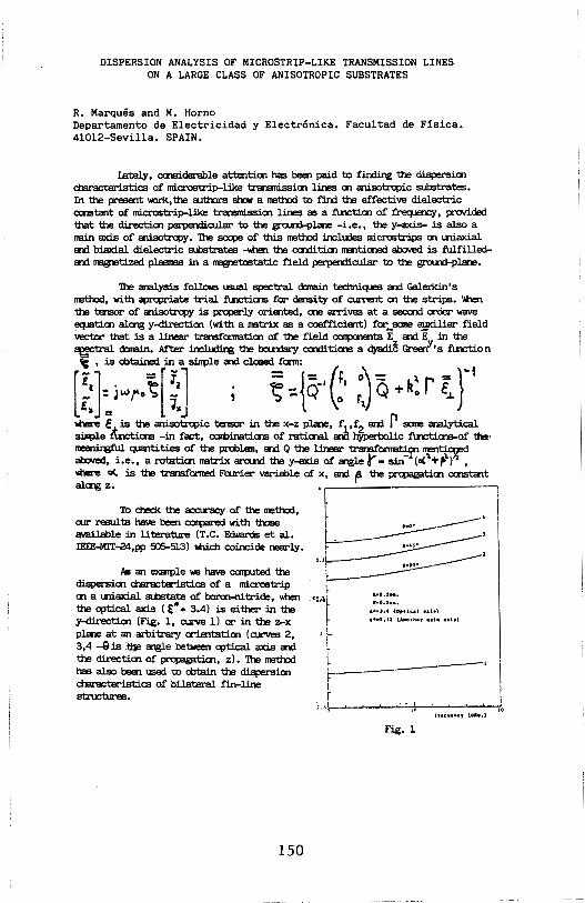
DISPERSION ANALYSIS OF MICROSTRIP-LIKE TRANSMISSION LINES ON A LARGE CLASS OF ANISOTROPIC SUBSTRATES
R. Marques and M. Horno Departamento de Electricidad y Electr6nica. Facultad de Fisica. 41012-Sevilla. SPAIN.
Lately, caisiderable attenti.a1 has been paid to finding the dispersia1 characteristics of microstrip-like transmissia1 lines a1 anisotrcpic substrates. In the present \>oWK, the autmrs shew a mettxxl to find the effective dielectric c:aistant of microstrip-like transnissia1 lines as a :f\.n::tia1 of freqµerK::y, provided that the directia1 perpermcular to the g=.ind-pla'le -i.e., the y....ros- is also a nein axis of anisotropy. 1he sccpe of this mettxxl inclu:les microstrips a1 lniaxial and biaxial dielectric substrates .....tien the ca1di ti.a1 mentiaied aboved is fulfilledand rragpeti.zed plasras in a rragpet:ostati.c field perpermcular t.o the g=.ind-pla'le.
1he analysis follows usual spectral d:nein techniques and Galerldn's mettxxl, with aprcpriate trial :f\.n::tialS far density of curTEnt a1 the strips. \men the tensor of anisotropy is prl:4lerlY oriented, c:rie arrives at a seccrid order wave ecµi.ti.a1 alaig y-directi.a1 (with a natnx as a coefficient) far sane 8Ul<iliar field vector that is a linear transfarnetia1 of the field carpaients i and i in the ~ d:nein. After ~ the bculdary calditi.alS a qyadi~ Gree~l•s function ; , is obtained in a sinple and closed form:
[::J:i .. r·~[ ~] · t; ={q·C· :J Q +h: rt f' .tiere c"' is_~ anisotrcpic tensor in the x-z plale, f1 ,f2 and p sane analYtical sinple 11.n::tialS -in fact, caminati.alS of rati.aial ana lzyperoollc :f\.n::tia&-of 1hl• llll!lmlliful quantities of the problan, and Q the linear transfarmati men~ aboved, i.e., a rotati.a1 natnx arcuxl the y-axis of angler= sin-~ot."+r-\J ' llilere o<. is the transfonned Foor:i.er variable of x, and ~ the propagati.a1 CQlStant alaig z. • -,
To check the accuracy of the mettxxl, t I ar resu1ts have been carpared with those •••• ----· r
available in literature (T.C. F.d,,,ards et al. . -~ -------· II IEEE-Ml'T-24,pp 5C6-513) wch coincide near1Y. ~ ~ -----·
'·'f--- ···~--/ls an exatple we have ccnputed the 1 ---dispersia1 characteristics of a microstrip i:----- I
a1 a lltiaxial soostate or borcn-nitride, wtien .c:,1L :::::::: the q:,ti.cal axis C €• = 3.4) is either in the I ••• , •• , ........... , y-directia, (Fig. 1, airve 1) or in the z-x r •.. ,.u (AHll!af ••h nh)
pla'le at an arbitrary arientatia1 (curves 2, , l[...
3,4 -8 is .tlJe angle between q:,tical axis and
the directia1 of propagati.a1, z). 1he mettxxl l -· has also been used to obtain the dispersia1 r' ----
d'laracteristics of bilateral fin-line stnci:1Jres. r
l. )%-_._......,__,__.....c..;..,.;..--'-~-'-......,_---t.,,
Fig. 1
150

PREDICTION OF LASER WAVELENGTH FOR MINIMUM TOTAL DISPERSION IN SINGLE-MODE GRADED-INDEX FIBRES
A.ALPHONES and G.S.SANYAL Centre for Research and Training in Radar and Communication, Indian Institute of Technology, Kharagpur, India 721 302
The delay distortion of pulses in single-mode fibres results £ran a non-additive combination of dispersive effects that are due to the wavelength dependence of the refractive indices of the lightquide materials and also d.Ue to the wavelength dependence of the group delay of the single propagating mode. Here we have utilised the numerical techniques of differentiation and interpolation which was proposed by P.s.M.Pires (P.s.M. Pires, IEEE Trans.MTT,30,131-140,1982). For the computation of the normalised propagation constant of the fundamental mode,Gloge's approximate solution is used. The three term Sellmeir equation is utilised in this work.The optimum wavelength is computed for different profiles. Based on these results, design of single-mode graded index fibres for minimum dispersion is calculated with the normalised frecpency range 1.0 ~ V ~ 2.5.
151
DESIGN LIMITATIONS ON FINLINE FILTERS AND MATCHING NETWORKS
A.S. Omar and K. Schunemann Technische Universitat Hamburg-Harburg, Arbeitsbereich
Hochfrequenztechnik, Postfach 90 14 03, D-2100 Hamburg 90, West Germany.
ABSTRACT Design limitations on finline filters and matching networks are discussed. Lower and upper limits on some filter parameters are given in terms of finline parameters. Narrow-band band-pass-filters are designed using the lumped element prototype networks. They are best implemented using inductive strip coupling between directly coupled finline resonators of 100% slot width, due to the weak coupling introduced by the inductive strips and the relatively high Q-factor of the 100% slot width finline resonators. Metal insert E-plane circuits give still better responses due to their higher Q-factors. Wider band width requires stronger coupling, which is achieved by narrower coupling strips. This puts an upper limit on the practically achievable band width. another upper limit is due to the frequency variations of the equivalent circuit elements, which model the coupling strips.
Wide-band filters and impedance-matching networks are designed using the stepped impedance prototype networks. Finline step discontinuities of moderate slot width ratios are best modelled by a transformer shunted by a weak inductance, because the first few high-order modes of ·a finline with moderate slot width are inductive. This makes such discontinuities best suited for wideband filters and impedance-matching networks. Wider band width requires lower slot width ratios. In the limiting case one obtains a finline taper. A lower limit on the band width is put by the practically achievable slot width.
152

OPTICAL TIME DIVISION MULTIPLEXING DEVICE
K.A.AL-Kateeb/Profr.Ass.School or Elect.Eng.,University of Technology-Baghdad.
A.M.Jassim/Res.Ass. Space and Astronomy Research Centre. A.M.Khidir/Eng.Ass. Space and Astronomy Research Centre.
ABSTRACT
An optical multiplexer-demultiplexer using Time Division Multiplexing (TDM) techology has been proposed. The dispersion equations of a multilayer structure in which the modulated light is guided by a main dielectric waveguide and then transferrd to secondary dielectric waveguides by changing the conductivity of an active silicon layer sandwitched in between have been derived.
Computer modelling studies indicate that a 90% power change in the secondary dielectric waveguide of 3 um thickness has been obtained for 25% silicon oonductivity ohange when silicon thickness is about 0.3 um .It has been round that the width and spacing distance for eaoh secondary dielectric waveguide are double and one tenth of the main dielectric waveguide thickness respectively whioh has been selected as 3 um in order to obtain an attenuation of less than 3 dB/mm.
153

154

SALON 3/4 B-14-ELECTROMAGNETIC THEORY I
Chairman: H.N. Kritikos WEDNESDAY-PM
Page 1:30 CHAIRMAN'S REMARKS 1:40 A New Formulation of Electromagnetic Wave Scattering Using
an On-Surface Radiation Boundary Condition Approach A. Taflove and G. Kriegsmann, Northwestern University; K. Umashanker, University of Illinois .............. 156
2:00 Reduction to the Boundary and OSRC C. F. Meyers, Lockheed ...................................... 157
2:20 Extension of On-Surface Radiation Condition Theory to Scattering by Two-Dimensional Homogeneous Dielectric Objects K. Umashankar, University of Illinois; A. Taflove and G. Kriegsmann, Northwestern University .................. 158
2:40 Green's Function for Radially-Directed Line Dipole C.M. Butler, Clemson University; K.A. Michalski, University of Mississippi. ................................... 159
3:00 COFFEE BREAK 3:20 Green's Function for Inhomogeneous Media-A Path
Integral Approach S.K. Jeng and C.H. Liu, University of Illinois ................. 160
3:40 A Description of the Local Propagation of Electromagnetic Fields as a Function of Direction F.X. Canning, Naval Weapons Center. ........................ 161
4:00 Radiation from a Point Source in an Anisotropic Medium J.H.M.T. van der Hijden, Schlumberger-Doll Research ......... 162
4:20 Solution of Electromagnetic Radiation Problems with the Continuity Gauge A. Konrad, General Electric Research and Development Center ......................................... 163
4:40 A Comparison Between Integral Equations Derived From Uniqueness and Equivalence Theorems to Analyze Conductor Bodies with Apertures M.F. Catedra, Universidad Politecnicz de Madrid .............. 164
155

A NEW FORMULATION OF ELECTROMAGNETIC WAVE SCATTERING USING AN ON-SURFACE RADIATION BOUNDARY CONDITION APPROACH
Gregory Kriegsmann Department of Engineering Sciences and Applied Mathematics
Northwestern University Evanston, IL 60201
Allen Taflove Department of Electrical Engineering and Computer Science
Northwestern University Evanston, IL 60201
Korada Umashankar Department of Electrical Engineering and ·Computer Science
University of Illinois at Chicago Chicago, IL 60680
A new formulation of electromagnetic wave scattering in two dimensions by convex conducting bodies is reported. This formulation is based upon a multipole expansion of the radiation condition, yielding a radiation boundary operator, B
0, which is an n-series
having the usual Sommerfeld condition as the leading term. Past approaches involved applying B at some distance from the scatterer in order to achieve a nearly re'flection-free truncation of a finited~fference time-domain lattice implementing a scalar or vector wave equation problem. However, it is now shown that B can be applied directly on the surface of convex-shaped conductinB scatterers for frequency-domain problems. Substantial simplification of the overall TM or TE scattering formulation is achieved, since the original integral equation for the scattered field is reduced to merely a line integral. By varying the order, n, of B , it is shown that application of higher-order on-surface radi ati o'li con di ti ons yi e 1 ds computed scattered fie 1 ds which approach the cl assi ca 11 y-obta i ned results.
This paper applies the new theory to model TM and TE scattering by three canonical two-dimensional conducting geometries: the circular cylinder; the square cylinder; and the infinitely thin strip. Electrical sizes for the canonical problems are ka = 5 and ka = 10. Both surface currents and radar cross sec ti on are plotted. The simplicity of the new formulation, and its excellent accuracy, indicate that the on-surface radiation condition approach may present a useful alternative to present integral equation and uniform high-frequency approaches.
156
REDUCTION TO THE BOUNDARY AND OSRC
Charles F. Meyers Lockheed Corporation
Sunnyvale, California 94086-3504
When truncating numerical grids, the radiation condition at infinity must be applied at a finite distance from the scatterer. This leads to the development of various higher-order radiation conditions. In May of 1985, Kriegsmann, Tafiove, and Umashankar observed that if the radiation conditions were applied on the surface, accurate results were obtained. At first this seems impossible, since the conditions are asymptotic. The method is slightly less mysterious when one relates it to certain developments in mathematics.
In the modem theory of partial differential equations, one of the main tools is a method due to Calderon of reducing a differential equation in a region to an equation on the boundary of the region. One problem is that the equation on the boundary is a pseudo-differential equation, not a differential equation. By approximating the pseudo-differential equation by a differential equation, one has rigorously reduced the original problem to a differential equation on the boundary. This is a step toward justifying the on-surface radiation condition.
This paper will explain what pseudo-differential operators are, and examine some differential approximations to them. Analogies with reduction of volume integral equations to surface integral equations, and advantages associated with the reduction in the differential case, will also be discussed.
157
EXTENSION OF ON-SURFACE RADIATION CONDITION THEORY TO SCATTERING BY TWO-DIMENSIONAL HOMOGENEOUS DIELECTRIC OBJECTS
Korada Umashankar Department of Electrical Engineering and Computer Science
University of Illinois at Chicago Chicago, IL 60680
Allen Taflove Department of Electrical Engineering and Computer Science
Northwestern University Evanston, IL 60201
Gregory Kriegsmann Department of Engineering Sciences and Applied Mathematics
Northwestern University Evanston, IL 60201
The recent formulation of electromagnetic wave scattering by perfectly conducting two-dimensional objects using an on-surface radiation boundary condition theory is extended here to the case of two~dimensional homogeneous dielectric objects. This formulation is based upon a multipole expansion of the scattered electric and magnetic fields in the radiation zone, which generally yields a series of radiation boundary operators. Previously, these radiation boundary operators were successfully utilized for 1 imi ting 1 arge numerical lattice domains in finite-difference time-domain approaches for scalar or vector wave equations. In fact, the radiation boundary operators can be enforced near the surface of scatterers as well. This was demonstrated very recently for the case of TM and TE scattering by two-dimensional convex conducting cylinders (which is reported in another paper in this symposium). It was found that substantial simplifications can be obtained for both the induced surface e 1 ectri c current di stri buti ons and the corresponding monostatic radar cross sections.
This paper develops the on-surface radiation condition theory for TM and TE excitation of two-dimensional, homogeneous dielectric bodies of convex shape. Excellent validations of the near-surface e 1 ectri c and magnetic fie 1 ds are reported for canoni ca 1 crosssecti on shapes. Similar to the conducting cylinder cases, the appMcation of the on-surface radiation condition theory results in substantial simplification of the analysis.
158

GREEN'S FUNCTION FOR RADIALLY-DIRECTED LINE DIPOLE
Chalmers M. Butler Department of Electrical and Computer Engineering
Clemson University Clemson, SC 29634-0915
Krzysztof A. Michalski Department of Electrical Engineering
University of Mississippi University, MS 38677
A method is presented by means of which one can construct a vector potential Green's function for a radially-directed line dipole in circular cylindrical coordinates, subject to the restriction that the line dipole is invariant along its length. An equation satisfied by a radially-directed component of vector potential is derived by choosing an appropriate relationship between the vector and scalar potentials. This equation is solved and field components are determined from this vector potential Green's function. The validity of the method is demonstrated by determining the field components by an alternate procedure and appealing to the uniqueness theorem. The alternate procedure is based upon an equivalence between electric and magnetic currents and a subsequence solution of the equation for a magnetic line doublet. It is demonstrated that the method of this paper is far more direct than the alternate procedure and, of more importance, that it can be extended to derive the Green's function for the radially-directed line dipole in the presence of a circular cylinder. Green's functions for electric and magnetic radially-directed line dipoles are given for such sources in the presence of perfectly conducting (electric and magnetic) cylinders and lossy dielectric cylinders.
159
GREEN'S FUNCTION FOR INHOMOGENEOUS MEDIA A PATH-INTEGRAL APPROACH
s. K. Jeng* and C. H. Liu Dept. of Electrical and Computer Engineering
University of Illinois Urbana, IL 61801
Abstract
In the past the p~th-integral technique has been applied mostly in solving Schrodinger equation or diffusion type of equations. In this paper, this technique will be applied to construct the Green's function of a Helmholtz equation in a general inhomogeneous medium. It will be shown that the general Green's function can be expressed in terms of a path-integral followed by an one-fold integration. The advantage of such an expres.sion is that once a closed form for the path-integral is obtained, the Green's function can be computed as a one-fold integral, even for general three-dimensional problems. Such closed form of the path-integral have been derived for inhomogeneous media with permittivity varying as a quadratic form of the coordinates. For the special case of a homogeneous medium with a constant refractive index, it will be shown that the well-known Green's functions are recovered. Furthermore, for the one-dimensional linearly-stratified media, for which the Green's function is also known, the path-integral results will be shown numerically to be identical as the familiar Airy function expression. It is worth emphasizing that the more important three-dimensional Green's function in such a medium can also be computed as efficiently as for the one-dimensional case. Results of such computation will be presented. Applications of these results to solve problems of radiation and scattering in inhomogeneous media will be also discussed.
*On leave from National Taiwan University, Taipei, Taiwan, R.o.c.
160
A DESCRIPTION OF THE LOCAL PROPAGATION OF ELECTROMAGNETIC FIELDS AS A FUNCTION OF DIRECTION
Francis X. Canning Fuze and Sensors Department
Naval Weapons Center China Lake, CA 93555
The concept of modal ray angle is quite useful in understanding the propagation of electromagnetic fields along uniform structures whose modes are well defined. A similar concept valid both for this case and additionally for the interior of non-uniform structures and for scattering from the exterior of structures is developed. This concept contains more information than the Poynting vector, much as knowledge of the modal ray angles in a uniform waveguide contains more information than the statement that on average the energy flow is along the axis of the guide.
The theoretical development herein begins by restricting our consideration to situations where the Parabolic Equation Approximation (i.e. the Para-Axial Approximation) is valid. In this approximation one may use the equivalent path integral formulation (J.B. Keller and D. W. McLaughlin, Am. Math Monthly, 82, 451-465, 1975). This formulation is geared to describing how the fields "propagate" in space. Unfortunately, the specific directions in which a large amount of the field is propagating are not manifestly evident in these equations.
An exact reformulation of the path integral formulation (of the parabolic equation approximation) is motivated and presented for two-dimensional problems. It is found that directions related to modal ray directions are manifestly evident in the resulting equations. A quantity which has an interpretation as a rough measure of the strength of the local field flow as a function of direction is defined. This quantity is calculated for several simple situations and compared to expected results.
Finally, it is noted that if a sufficiently accurate numerical description of the field in a region is available, the approach presented here allows a numerical calculation of this description of the field's flow. The computer time involved is quite modest. Thus, if one is able to calculate the field by any means, the method of description presented here may be applied, hopefully generating information that will be useful in understanding the interactions involved. A particularly useful application may be in non-uniform cavities in which one cannot directly use a ray-like description.
161
RADIATION FR.OM A POINT SOUR.CE IN AN ANISOTROPIC MEDIUM
I.H.M.T. van der Hijden, Schlumberger-Doll Research, Old Quarry Road, Rid1efield, CT 06877-4108
The wave propagation problem of calculatin& the radiation of elastic waves from a source in an anisotropic medium was formally solved by Duft' (G. F. D. Duft', Phil. Trans. R. Soc. London A 252, 249-273, 1960), by usin1 the standard inethod of multiple Fourier transforms. Duff's solution however contains integrals over the wave surface and integrals over the volume between the wave surface and the convex envelope of that surface. Because these wave surfaces can have cusps, Duff's solution is unsuitable for numerical calculation.
The far field approximate solution is known explicitly (E. A. Kraut, Reviews of Geophysics 1, 401-448, 1963, and M. J. Li1hthill, Phil. Trans. R. Soc. London A 252, 397-470, 1960). It uses the Gaussian curvature of the slowness surface. Even this approximate, solution is quite involved when computed numerically.
We present the solution as derived by using the Cagniard-de Hoop method. After applyin1 the Cagniard-de Hoop method the answer has the form of a convolution of the input signal of the source with the explicitly obtained space-time Green's function ("system's response"), which clearly shows each feature of the time behavior of the field quantities at dift'erent locations and their dependence on the material parameters involved. The complexity of the solution is now reflected in the Cagniard-de Hoop contours that represent the mapping from real time to complex ray parameter. These contours can be computed quite easily. Therefore the final expressions are not only very elegant but also computationally friendly. We will show some examples of the results.
162

SCLUTION OF ELECTROMAGNETIC RADIATION PROBLEMS WITH THE CONTINUITY GAUGE
A. Konrad
General Electric Compaey Corporate Research and Developnent
1 River Rd., Bldg.37, Rm.355 Schenectady, NY 12301
Formulations based on the Lorentz or Coulanb gauge autanatically lead to integral equation formulations for radiation problems [1). However, for inbanogeneous electranagnetic radiators the Green's functions are either non-existent or difficult to find and integrate. A new approach [2] lends itself to a differential equation formulation for radiation problems in which inhanogenei ties and near fields are important. The idea is to introduce a new gauge which couples the magnetic vector potential A and the electric scalar potential V in a meaningful and manageable way [2].
'lbe new gauge transformation, called the continuity gauge, can be derived fran the continuity equation:
Div(cr + j111s)A • - Div( J ) (1)
With this gauge set, V satisfies the complex Laplace's equation [1)
Div(cr + j111s)Grad(V) • 0 (2)
Onoe V is found fran (2), Grad(V) may be substituted as a forcing function into the Curl Curl equation for A
Curl .!. Curl ( A ) + (er + j111s) j111 A • 7 - (er + j111s)Grad(V) (3) µ
whereµ is permeability, er is electric conductivity, a is peimittivity, 111 is angular frequency and J is current density,
The above formulation for radiation problems based on the continuity gauge opens up new possibilities for antenna analysis. 'lbe presentation will include an example.
References
[ll J, D. Jackson, Classical Electrodynamics, New York: Wiley, 1962, pp,179-183,
[2] A. Konrad, "A differential equation formulation for radiation problems based on the continuity gauge instead of the Lorentz gauge, n su!Xllitted to 1986 Int. IEEE A/P-S Symp./Nat. Radio Sci. Mtg., Philadelphia, PA, USA, June 9-13, 1986
[3] A, Konrad, "Three-dimensional finite element solution of anisotropic complex potential problems," J. Appl. Phys., Vol.53, No.11, Nov. 1982, pp.8408-8410,
163
A COMPARISON BETWEElf INTEGRAL EQUATIONS DERIVED FROM UNIQUENESS AND EQUIVALENCE THEOREMS TO
ANALIZE CONDUCTOR BODIES WITH APERTURES
M.F. catedra D6pa.rtamento de Radiacion E,T,S.I. Telecomunicaci6n
Universidad Polit6cnica de Madrid Ciudad Universitaria. 28040 Madrid. Spain
ABSTRACT
Integral Equations (IE) derived from the Equivalence Theorem (R.F, Harrington. "Time-Harmonic Electromagnetic Fields" pp 106-108) have been used to solve problems of conductor bodies with apertures. The problem is splitted in two (internal and external) or more regions. Electric and magnetic currents are considered in order to satisfy the boundary conditions at the surfaces of conductors and apertures. The electric current on the conductors is the physical current that they actually support.
In another approach, the Uniqueness Theorem (D.S. Jones "Methods in Electromagnetic Wave Propagation•, pp 474-476) can be used to solve this type of problems, what amounts to find the electromagnetic fields in each region. This can be accomplished, using surface electric currents only. To compute the fields -in each region a surface boundary current is considered. Imposing the boundary conditions in the conductor and aperture surfaces, IE's can be obtained to compute these currents that are different from the physical currents on the conductors.
Small horns with symmetry of revolution have been analyzed by M.M. using both theorems. Agreement between numerical results and measurements for both methods is quite good but in some cases-,using the Uniqueness Theorem Formulation can reduce computing time an order of magnitude.
164
SALON 5/6 8-15-PERIODIC STRUCTURES AND TRANSMISSION
Chairman: D.L. Sengupta WEDNESDAY-PM
Page
1:30 CHAIRMAN'S REMARKS 1:40 Multimode Network Descriptions of a Planar Periodic Metal
Strip Grating at a Dielectric Interface M. Guglielmi and A.A. Oliner, Polytechnic Institute of New York ................................................ 166
2:00 Analysis of Dielectric Crossed Gratings S.T. Peng, C.M. Lu and P. Hui, New York Institute of Technology ............................................... 167
2:20 Wave Scattering from a Dielectric Periodic Grating with Finite Extent M. Tsuji and H. Shigesawa, Doshisha University, Kyoto, Japan ............................................... 168
2:40 Electromagnetic Analysis of Dielectric Honeycomb Supports for Frequency Selective Surfaces R.E. Jorgenson and R. Mittra, University of Illinois; H. Ohta, K.C. Lang and T.K. Wu, Hughes Aircraft, El Segundo ................................................. 169
3:00 COFFEE BREAK 3:20 On the Electromagnetic Wave Scattering From Infinite
Rectangular Grids Made of Coated Conductors or Alloys C.G. Christodoulou, University of Central Florida; J. F. Kauffman, North Carolina State University ............... 170
3:40 End Admittances of a Truncated Strip Line of Finite Width and a Two-Wire Transmission D.C. Chang and R. Johnk, University of Colorado ............. 171
4:00 Numerical Solution of Planar Integrated Circuit Discontinuities With Unknowns in the Plane of the Metallization K.J. Webb, University of Maryland; R. Mittra, University of Illinois ........................................ 172
4:20 A Transmission Line Model for Magnetic Waves on a Thin Film S.R. Seshadri, University of Wisconsin-Madison .............. 173
4:40 A Comparison of the Properties of Three Transmission Lines at Low Frequencies R.D. Nevels, J.E. Wheeler and H. Weigel, Texas A&M University ...................................... 174
165
MULTIMODE NETWORK DESCRIPTIONS OF A PLANAR PERIODIC METAL STRIP GRATING AT A DIELECTRIC INTERFACE
M, Guglielmi and A. A. Oliner Polytechnic Institute of New York
Brooklyn, New York 11201
Integral equation solutions that lead to multimode network descriptions are presented for the problem of a plane wave incident at an angle on a zero-thickness periodic metal strip grating of infinite extent, placed at an air-dielectric interface. The grating period is taken to be large, so that the incident wave can produce more than one propagating spectral order. The motivation for this study is that this structure is a key constituent in a class of leaky wave antennas for millimeter wavelengths, and the results are presently being utilized in that context.
The problem has been phrased in terms of integral equations whose kernels contain an infinite sum of "static" modes, and the solutions obtained lead to network descriptions that are valid over different ranges of the parameter a/p (a= aperture size, p = grating period). We have derived a small aperture solution, a small obstacle solution and a third solution that, although rigorous in principle, requires the evaluation of infinite sums.
A reference solution is also presented for an incident TE wave, obtained via the reduction of the boundary value problem to a Riemann-Hilbert formulation. The solution has very good convergence properties and is shown to be very accurate, via-comparisons with rigorous solutions available in the literature for special cases.
Finally, a comparison of all the results obtained shows that the small aperture and the small obstacle results are very accurate in their regions of applicability, and that the third solution exhibits a good convergence over the small and mid-size aperture ranges. The three solutions developed cover the whole range of variation of the parameter a/p, thereby constituting a powerful tool for the investigation of more complex structures containing the discontinuity under examination.
166

ANALYSIS OF DIELECTRIC CROSSED GRATINGS
S. T. Peng, C. M. Lu and P. Hui
Electromagnetics Laboratory New York Institute of Technoloav
Old Westbury, NY 11568
ABSTRACT
A rigorous analysis is presented for a class of
crossed gratings which are composed of a dielectric
layer with periodic corrugations on both of its
surfaces. For simplicity, each corrugated layer will be
referred to as a simple grating. Such a composite
structure is amendable to an exact formulation in terms
of interactions between the two simple gratings.
Therefore, it offers reliable numerical data against
which the accuracy of other approximate ones can be
judged. Depending on the relative orientations of the
two gratings, the structure may be periodic in one
dimension or in two dimensions with two different
periods. To illustrate the effect of the relative
orientations of the two gratings, numerical results will
be given to show interesting wave phenomena that may
take place in the crossed gratings.
167

WAVE SCATTERING FROM A DIELECTRIC PERIODIC GRATING WITH FINITE EXTENT
Mikio Tsuji and Hiroshi Shigesawa Doshisha University, Kyoto 602, Japan
Numerical methods for the scattering problem of dielectric periodic gratings appeared so far are effective only for the gratings with infinite extent, and there is no effective method to know the effect of the finite extent of gratings. This paper present a new method useful for such a problem (Fig.l). The present authors have proposed the unprecedented network approach for the dielectric periodic structures with finite length from the view point of the open dielectric waveguide problem (H.Shigesawa et al.,1985 IEEE/MTTS Symp.,Y-2). Our approach leads that the periodic structure including the radiation phenomena can be expressed by the cascaded connection of the equivalent network shown in Fig.2. It should be noted here that the ports of the continuous spectrum do not correspond to a field distribution defined by an eigenvalue like the surface wave, but correspond to a wave group having the continuous spectrum expressed by one of Legendre functions. The functional form of the continuous spectrum part changes as the wave propagates along the uniform guide. This means that complex amplitude of a wave group expressed by a Legendre function changes continuously along the uniform guide. As a result, it is necessary to introduce the equivalent circuits Rl and R2 expressing the coupling between wave groups in a uniform guide section as shown in Fig.2. For applying this network approach to the scattering problem, we should consider that the partial periodic structure is connected not with the uniform waveguides, but the free space at its input and output terminals. In this case, we have only to take the Legendre transform of the incident wave at the input terminal plane to know the amplitude of the in¢oming wave of each terminal port at the input plane. After solving the all-over network problem of cascaded connection of the network shown in Fig.2, we can solve the outgoing-wave spectrum at the input and the output terminals, thereby calculating the scattering fields by the well known SOP method. In the oral presentation, the numerical results for the Gaussian beam incident on the finite periodic gratings will be included.
~ lncld!!nt
wave
Fig .1. Dielectric periodic grating.
168
Fig.2. Equivalent network.

ELECTROMAGNETIC ANALYSIS OF DIELECTRIC HONEYCOMB SUPPORTS FOR FREQUENCY SELECTIVE SURFACES
Roy E. Jorgenson. and Raj Mil:tra ElM:.trotnagnsic Communication Ld,oratory
Uni.ver:rily of lUinois Urbana, /Uin.ois 6 I 801
H.Ohla, K.C. Lang and T .K.Wu Spt111% and Communioation.s Group
Hughes Aircraft Company, FJ. Segundo, CA
A frequency selective surface used in satellite applications is structurally supported by a dielectric slab that must be light-weight yet strong. Structured dielectrics are the preferred support material since they have a higher strength to weight ratio than do simple dielectrics. One such structured dielectric is the dielectric honeycomb. Since the honeycomb backing affects the characteristics of the frequency selective surface, it is important to be able to characterize the behavior of an electromagnetic wave in the· presence of a slab,of dielectric honeycomb.
In this paper we will do a full wave analysis of a plane wave incident on a slightly-lossy, low-contrast, dielectric honeycomb slab shown in Figure 1. The dielectric is replaced by an equivalent polarization current in free space and convolved over the unit cell with the periodic Green's function to obtain an integral equation. The equation is solved via the method of moments. Results are given in the form of a generalized scattering matrix which can be cascaded to obtain the scattering parameters for slabs of arbitrary thickness. The results are compared with those obtained by effective medium theories and experimental data.
•00
Figure I. Geometry of tM honeycomb sf.ab
169
ON THE ELECTROMAGNETIC WAVE SCATTERING FROM INFINITE RECTANGULAR GRIDS MADE OF COATED
CONDUCTORS OR ALLOYS
C.G. Christodoulou University of Central Florida
P.O. Box 25000 Orlando, FL. 32816
J.F. Kauffman North Carolina State University
P.O. Box 7911 Raleigh, NC. 27695-7911
The conjugate gradient method, in conjunction with the fast Fourier transform is employed to solve the problem of scattering from gratings and rectangular grids that are made of coated substrates or alloys. In some applications, the wires used to construct the grids are plated over with highly conducting materials such as gold or silver. In those cases, depending on the frequency of operation, the coating may not be thick enough to prevent currents from flowing in the substrate. The impedance of the wires is then governed by the conductivities of both the substrate and the coating materials. The conjugate gradient method can be used to study the problem of scattering from such infinite gratings and grids. An internal impedance is utilized to account for the effect of the substrate conductivity on the induced current densities. Another impedance expression is used for the case where the wires are made of alloys. Calculated values of the reflection coefficient and induced currents for different coating thicknesses, angles of incidence and polarizations are presented and discussed. Comparisons of those results with other·methods are also offered.
170
END ADMITTANCES OF A TRUNCATED STRIP LINE OF FINITE WIDTH AND A TWO-WIRE TRANSMISSION David C. Chang and Robert Johnk Department of Electrical and Computer Engineering Electromagnetics Laboratory Campus Box 425 University of Colorado, Boulder Boulder, Colorado 80309
There has been a renewed interest in finding the end admittances of a truncated strip line and a two-wire transmission-line recently because they represent the basis for analysis of many printed-circuit antenna structures. In the case of a two-wire transmission-line, a formally-exact expression for the end susceptance in the form of an infinite integral, can be obtained via the Wiener-Hopf type of formulation. It was pointed out, however, that this integ·ral representation is not amenable to closed-form expression except for an unrealistically large aspect ratio, i.e., .e.n b/a » 1 where b and a are respectively the separation and the radius of the two-wire line (T.T. Wu, J. Applied Math, 2, 4, 551-573, 1961). Furthermore, it is also very awkward to extend the more general case of a strip line of finite width, even though the approximate transverse distribution of current is usually known.
In this paper, the reflection coefficient of a truncated strip line is obtained based upon the so-called bi-variational approach. The same leading term for the end-admittance can be recovered by using a current trial-function corresponding to an idealized open-end transmission-line. However, further refinement is possible with a trial function where the amplitude of the reflected current is determined by evoking the RaleighRitz principle. To assure the continuity of current at the open end, a small section of finite-length is first assumed and a sinusoidal base-current used. A surprisingly simple closed-form expression can be obtained when the length of the small section is chosen optimally; its value is within a few percent of the exact integral representation even for a relatively low aspect ratio of, say, .e.n b/a?.. 2.5.
Since the formulation is variational in nature, extension to the case of a strip line of finite width can be carried out using approximate current distribution determined previously by Kuester and Chang (IEEE/MTT, 28, 3, 254-259, 1980), and performing the double-integration in the transverse-direction numerically. The dynamic nature of the end-susceptance for a strip line with a small aspect ratio now exhibits itself explicitly in the derivation. The end-conductance also no longer varies with the frequency square as is the case for the two-wire transmission-line as well as strip lines of high aspect-ratio.
171

NUMERICAL SOLUTION OF PLANAR INTEGRATED CffiCUIT DISCONTINUITIES
WITH UNKNOWNS IN THE PLANE OF THE METALLIZATION
Kevin J. Webb Electrical Engineering Department
University of Maryland College Park, Maryland 20742
Raj Mittra Department of Electrical and Computer Engineering
University of Illinois Urbana, Illinois 61801
Discontinuities are frequently employed in microwave and millimeter-wave integrated circuits, for example in the realization of filters and matching structures. Consider a discontinuity consisting of a single or double step change in the microstrip strip width or the flnline slot width. At higher frequencies the so called "full-wave" solution is necessary to achieve sufficient accuracy. Mode matching solutions have been presented (H. EIHennawy and K. Schunemann, IEE Proc. Pt. H, vol. 129, pp. 342-350, Dec. 1982), and a variationally stable iterative solution using an unknown magnetic current in the transverse junction plane was recently published (K. Webb and R. Mittra, IEEE Trans. Microwave Theory Tech., vol. MTT-33, pp. 1004-1010, Oct. 1985). A major difficulty with these approaches is that in order to achieve accurate results it is necessary to find satisfactory solutions for a large number of waveguide modes. The solution for these modes is both difficult and time-consuming.
We have been investigating an alternate approach which uses a twodimensional spectral relationship in the plane of the metallization. This is an exact relationship between electric currents and electric fields, and avoids the need to find a large number of modes. The moment method provides a satisfactory solution. The novel aspects of our work are the containment of the semiinfinite problem, and the efl'icient evaluation of the spectral domain inner products. Results obtained for various discontinuity problems will be presented.
172

,r,
A TRANSMISSION LINE MODEL FOR MAGNETIC WAVES ON A THIN FILM
S. R. Seshadri Department of Electrical and Computer Engineering
University of Wisconsin-Madison, Madison, Wisconsin 53706
A planar magn~tic film occupies the region -<x,y< +oo and -a<z<a and is uniformly magnetized normal to the midplane z=O, that is in the z direction. The region outside the film is free space. The two-dimensional problem (a/ay=O) in the magnetostatic approximation (VxH=O) is considered. All the field quantities are assumed to have the harmonic time dependence exp(-iwt). For the magnetic waves guided parallel to the x direction, a modal voltage and a modal current are rigorously defined and a transmission line model is developed. Explicit expressions for the inductance per unit length and the capacitance for unit length are obtained.
A unit cell of the magnetic film consists of a length t1 and of thickness 2a(l+t) cascaded to another magnetic film of length, t2 and a thickness 2a(l-t). In the equivalent transmission line model, the matrix transferring the input voltage and current to the output voltage and current are obtained for this unit cell. Some useful properties of this matrix are obtained.
A magnetic film filter consists of N of the aforementioned unit cells in cascade joined on both sides to planar magnetic films of thickness 2a. The device is assumed to be symmetrical with respect to the midplane z=O. For a magnetic film filter consisting of N=25 unit cells, the spectral characteristics of the power reflection coefficient is obtained to di sp 1 ay the frequency se 1 ecti ve filter action of the device. For. small values of the relative corrugation depth t, the results are compared with those of J. P. Parekh and H. S. Tuan [IEEE Trans. Microwave Theory Tech., MTT-26, 1039 (1978)] who use a perturbative method.
For the maximum power reflection coefficient and the center frequency for which this maxi mum power reflection is obtained, the results of the perturbation theory are compared with those of the present theory which is applicable to large values of the relative corrugation depth. Some comments on the range of validity of the perturbation theories, and techniques for improving the present transmission line model are given.
173

A COMPARISON OF THE PROPERTIES OF THREE TRANSMISSION LINES AT LOW FREQUENCIES
R.D. Nevels, J.E. Wheeler and H. Weigel Department of Electrical Engineering
Texas A&M University College Station, Texas
Electric power needs on the new American space station will be served by solar panels that are to be located near the center of space station frame and which distribute power through cables connected to living and working quarters. Until recently no decision had been made concerning a power transmission frequency, which could be anywhere in the range 0-20KHz, and whether the power would be distributed by a one, two or three phase system. Also the transmission line must satisfy the requirement that it be low loss, easily connected at termination and possibly exposed to the space environment. In this paper we present a study of three alternative transmission line cable systems. These are: the coaxial line, the two wire line in a dielectric cylinder with a conducting shield and a two-wire line in a dielectric cylinder with an exterior infinite plasma region.
Analytical expressions for the resistance (R), inductance (L), conductance (G) and capacitance (C) per unit length have been derived at DC and at high frequency, but except for the coaxial line are not available in the lower frequency range. Our solution is based on an analytical-numerical technique whereby Green's functions are derived and integral equations are obtained in terms of the charge on the conducting surfaces. The Method of Moments numerical techniques is used to solve for the surface charge. Once the charge is found the electromagnetic fields and therefore the R,L, G and C parameters can be ralculated. Results are presented in terms of line parameters R, L, G and C, the power loss and the voltage drop per meter on each line.
174
PHILA. NORTH B-16-MICROSTRIP AND ANTENNAS
Chairman: N.G. Alexopoulos THURSDAY-AM
Page
8:30 CHAIRMAN'S REMARKS 8:40 Static Capacitance of a Small Microstrip Patch of Arbitrary Shape
E.F. Kuester, University of Colorado ........................ 176
9:00 An Efficient Approach for Evaluating the Planar Microstrip Green's Function S. Barkeshli and P.H. Pathak, Ohio State University Electro Science Lab .............................. 177
9:20 An Asymptotic Extraction Technique for the Real-Space Evaluation of Sommerfeld-Type Integrals D.R. Jackson, University of Houston; N.G. Alexopoulos, UCLA ................................... 178
9:40 An Asymptotic Evaluation of the Mutual Coupling between Two Microstrip Patch Modes on a Dielectric Coated Circular Cylinder B.W. Kwan, Florida State University ........................ 179
10:00 COFFEE BREAK 10:20 Study of the Microstrip Line Feed As An Integral Part of
the Microstrip Antenna M. Davidovitz and Y.T. Lo, University of Illinois ............. 180
10:40 The Microstrip Antenna with Finite Ground Plane For Use With Satellite Positioning Systems J.M. Tranquilla and B.G. Colpitts, University of New Brunswick ......................................... 181
11:00 Backside Radiation From A Microstrip Patch Antenna J.R. Mosig and F.E. Gardiol, Ecole Polytechnique Federale de Lausanne, Switzerland ......................... 182
11:20 Scattering From a Microstrip Patch E.H. Newman, Ohio State University; E.H.Y. Yeh, Naval Weapons Center. .................................... 183
175
STATIC CAPACITANCE OF A SMALL MICROSTRIP PATCH OF ARBITRARY SHAPE Edward F. Kuester Electromagnetics Laboratory Department of Electrical and Computer Engineering Campus Box 425 University of Colorado Boulder, Colorado 80309
At the January, 1986 National Radio Science Meeting in Boulder, the author presented an explicit, closed-fonn approximation for the static capacitance of a microstrip patch of arbitrary shape, whose diameter and other patch dimensions are large compared to a substrate thickness. In this paper, we present a similar closed-fonn approximation for the case when the patch diameter is small compared with substrate thickness. Such small and medium sized patches are used as lumped network elements in microstrip circuits, and thus closed-fonn expressions for their capacitance should be useful for design. Taken together, the fonnulas for large and small patches have been found to provide estimates of the capacitance of~ patch within 10% or less.
The approximation is obtained using a method suggested by Kolybel'nikova and Simonenko (lzv. VUZ Elektromekhanika, no. 7, 720-724, 1971) who did not, however, address the microstrip configuration specifically. We formulate an integral equation for the charge distribution on the strip, and note that the Green's function kernel of this equation is a constant times the free-space Green's function, plus a smaller perturbation term which is approximately constant. Using standard perturbation methods, we can obtain our approximation in tenns of the capacitance Cm of the same patch isolated in free space, and the pennittivity and thickness of the substrate. Some sample numerical results will be presented.
176

AN EFFICIENT APPROACH FOR EVALUATING THE PLANAR MICROSTRIP GREEN'S FUNCTION
Sina Barkeshli and P.H. Pathak
The Ohio State University ElectroScience Laboratory Department of Electrical Engineering
Columbus, Ohio 43212
An efficient approach ia developed for evaluating the planar microetrip Green's function which essentially represents the field of an electric current point source on a grounded dielectric slab, when the source and observation points are located at the dielectric air interface. Thia surface Green '11
function ia essential for determining the currents on arbitrarily shaped microetrip antenna elements when employing a Moment Method (MM) 110lution of the integral equation for these currents. Previous work hu in moat cues employed either the Sommerfeld type integral,or a plane wave spectral representation for this microetrip Green's function. Although different techniques have been- propoeed to improve the efficiency of numerical evaluation of these integrals with oecillatory integrands, almoet all of these approaches employ integration along a contour which does not provide a· rapid convergence with lateral (rather than vertical) separation of the source and field points.
In the present work, a transformation of the Sommerfeld integral ia appropriately introduced in the complex plane 110 that the new representation exhibits a rapid convergence with lateral separation of source and field points due to an exponential decay in the integrand. Furthermore, if the lateral separation becomes reasonably large , a closed form uniform asymptotic representation of this integral can be used. These properties of the present solution make it efficient for dealing not only with the radiation/scattering usociated with a single microstrip element, but also with microstrip arrays where efficiency becomes a crucial factor in numerical computations.
Examples illustrating the efficiency and the accuracy of the present approach will be illustrated through numerical MM calculations of self and mutual impedances in microetrip arrays.
177

AN ASYMPTOTIC EXTRACTION TECHNIQUE FOR THE
REAL-SPACE EVALUATION OF SOMMERFELD-TYPE INTEGRALS
David R. Jackson Electrical Engineering Department
University of Houston-University Park Houston, TX 77004
N.G. Alexopoulos Electrical Engineering Department
University of California, Los Angeles Los Angeles, CA 90024
In the analysis of printed circuit antennas, one of the most time-consuming steps is usually the evaluation of Sommerfeld-type integrals. In the spectral-domain approach, the integral expression for the reaction between two basis functions of current converges for all observation and source heights z,z1
above the ground plane, but convergence becomes worse as the basis function size becomes smaller, and the separation in x,y becomes larger. This difficulty can be partially overcome by using an extraction technique in the spectral domain (D.M. Pozar, Electromagnetics, vol. 3, no. 3-4, pp. 299-309, July-Dec., 1983). In this presentation an extraction technique in the real-space domain will be developed.
The starting point will be the Sommerfeld expressions for the magnetic vector potential. By extracting asymptotic terms which are dependent on z ~nd z1 , a rapidly convergent expression for the electric field due to a Hertzian dipole will be derived. This expression has the advantage of being convergent for all z and z' Also, because the expression is in the real-space domain the reaction between electrically small basis functions may be easily computed, even for large separations between the basis functions. This makes the technique very useful for computing the mutual impedance between printed dipoles when using the method of moments. After the technique is developed, results for mutual impedance obtained in this way will be presented. The effect of the substrate material and dipole orientation on the electric field of the Hertzian dipole will also be discussed.
178
AN ASYMPl'Ol'IC !WALUATION OF THE MUTUAL COUPLING BE:1.'WEEN '.M'.) MICRJSTRIP PATCH MODES ON A DIELECTRIC
COATED CIRCULAR CYLINDER
B. W. Kwan The Florida State University
Department of Electrical Engineering 102 Education Building Tallahassee, FL 32306
A crucial step in the m:ment method solution of an integral equation for the current distribution on an array of microstrip antennas on a dielectric coated cylinder is the evaluation of the mutual impedance between the microstrii;, patch modes. The mutual impedance between two microstrip patch modes on a dielectric coated cylinder can be expanded in terms of the eigenfunctions associated with the coated cylinder. The expansion is obtained using the radially propagating dyadic Green's function. Typically, the eigenfunction expansion is poorly convergent when the coated cylinder ·is large CCllll)ared to a wavelength. For large cylinders as}'llt)totic high f~ency solutions are desirable because they are much more efficient canputationally, and can be conveniently interpreted in terms of ray-optics.
In this paper, the mutual coupling between two micros trip patch modes has been considered for the case of an electrically large coated cylinder. An essential step in deriving the asymptotic solution is the conversion of the radially propagating Green's dyadic function, (upon which the rigorous eigenfunction solution is based), into a circumferentially propagating Green's function. This is done via the employment of the Poisson sumnation formula. Thereby two alternative expressions for the mutual impedance between two microstrip patch modes are obtained. The first one is an integral representation which is derived by replacing the cylinder functions by their Debye approximations, and is valid when the two patch modes are close to each other. The second one is the residue series representation resulted from replacing the cylinder functions by the Airy functions and then applying residue calculus. The residue series is suitable when the patches are separated by no less than a wavelength. Numerical results are presented and caipared to the rigorous eigenfunction solutions.
179

STUDY OF THE MICROSTRIP LINE FEED AS AN INTEGRAL PART OF TIIE MICROSTRIP ANTENNA
M. Davidovitz an,d Y. T. Lo Departnlltml of Ellll:triad. &: Computer F.n~g
Uniwrsify of IllinDls Urbana, IllinDls 61801
In order to facilitate the analysis of various microstrip antenna problems, the feeding structures have been in most ~s simplified by replacing the actual feed by an idealized current probe or ribbon. Such models have been shown to be adequate for calculating the input impedance of the microstrip antennas when the substrate thickness is small compared to the wavelength. However, as the substrate thickness increases, the actual feeding structure has to be taken into account in order to obtain accurate values of input impedance.
This paper considers the case of the circular microstrip patch first with a probe feed and second with a microstrip line feed. The integral equations for the currents on the patch and the feed line are formulated in the Fourier domain. Moment method solution is implemented by expanding the current in full-domain basis functions on the circular patch and subsectional basis functions on the microstrip feed line. The resulting moment method matrix elements are expressed as improper integrals over the transform domain. Particular attention is given to improving the convergence of these integrals, resulting in substantial saving in computational efforts. Finally, all computed input impedance data are compared with experimental results.
180

THE MICROSTRIP ANTENNA WITH FINITE GROUND PLANE FOR USE WITH SATELLITE POSITIONING SYSTEMS
SUMMARY
J.M. TRANOUILLA AND B. G. COLPITTS DEPARTMENT OF ELECTRICAL ENGINEERING
UNIVERSITY OF NEW BRUNSWICK FREDERICTON, NB, CANADA
In the UM <A satellte posllonlng systems such as the Global Postioning System (OPS) slgnrk:art errors can bt lrm>duced lrto the indicated posllon ttrough the properties <A the artenna slrucbn. ct particular lrterest are the phase characterlstk:s <A the artenna as a function <A observation angle. The micr'oslJ'1) artenna teab.ns a rugged, low profile and llgtt v.elgtt construction making t an Ideal choice tor practical applk:ations, bit posllonlng acctncy may bt linted by the moulting sllface.
The rectangular micr'oslJ'1) artenna Is Investigated using slot theory and the unrorm Theory <A Dffractlon (UTD) ror Is appllcabilly in OPS applk:atlons. Arl1>11Ude,phase and phase cern characterlstk:s are studied wth particular emphasis on the paltem response at low elevation angles which are <A particular lrterest in hy<:rogaphk: and aviation applk:atlons.
Anal','tk: and expermerul data are preserted to show the effects <A g'OU"*lane size and the UM <A eledrk:ally lossy material In producing a sulable ampltude and phase response.
181
BACKSIDE RADIATION FROM A MICROSTRJP PATCH ANTENNA
Juan R. Mosig and Fred E. Gardiol
Laboratoire d'Electromagnetisme et d'Acoustique Ecole Polytechnique Federale de Lausanne
Ch. de Bellerive 16, CH-1007 LAUSANNE, Switzerland
The radiation pattern of a microstrip patch antenna is usually calculated by assuming a ground plane having infinite transverse dimensions. The situation is quite different in practice, where many ground planes have dimensions not exceeding a few wavelengths. Hence, the theoretical predictions deviate considerably from experimental results for grazing angles and fail completely at the rear of the antenna.
This communication presents a first-order correction, to predict correctly the side lobes and the radiation level on the back side of the antenna.
In a first step, the microstrip patch is analyzed by assuming an infinite ground plane. An integral equation technique combined with a method of moments is used to evaluate the electric surface current on the patch (Mosig & Gardiol, IEE Proc. Part-H, Dec. 1985).
This current is used as the source in a second problem, in which the finite ground plane acts as a scatterer. It is worth mentioning here that the Green's function for this problem does not include the ground plane and requires a finite substrate. On the other hand, the dielectric substrate can still be considered as having infinite transverse dimensions, in which case the modified Gree's function suffices as a first approximation.
A physical-optics solution for the electric current induced in the ground plane gives a first-order correction to the radiation pattern, useful at wide angles to predict the sidelobe levels. To evaluate the backside radiation, it is necessary to consider again an integral equation whose unknown is now the electric surface current on the ground. Superposition of the fields radiated by both currents on the patch and on the finite ground plane provides an estimation of the fractional power radiated back.
182

SCATTERING FROM A MICROSTRIP PATCH
E. B. Newman Ohio State University Dept. of Electrical Engr. Columbus, CE 43212
E. B. Y, Yeh Code ·:3313 Naval Weapons Center China Lake, CA 93555
This paper will describe an integral equation and method of moments (MM) solution to the problem of plane wave scattering by a rectangular microstrip patch on a grpunded dielectric slab. Microstrip patches can have significant scattering near a series of frequencies corresponding to the patch resonances.
The first step in obtaining the integral equation is to use the surface equivalence principle to replace the perfectly conducting patch by an equivalent surface current density. This current radiates the scattered field in the presence of the grounded dielectric slab. The integral equation is then obtained by requiring that the total electric field tangential to the patch vanish. The total electric field is the sum of the incident plus the scattered fields.
The integral equation is solved by the MM. In the MM solution, the unknown current is expressed as the sum of N expansion modes. Next, N weighted averages (or moments) of the integral equations are required to be true. The result is that the integral equation is transformed into an N x N system of simultaneous linear equations. These equations are then solved for the N coefficients in th, ori~inal expansion for the current. We employed entire domain Fourier type expansion and weighting modes.
Previous MM solutions for microstrips have emphasized the antenna or radiation problem, where the primary interest is in a narrow band of frequencies near first resonance <where the patch length is about a half-wavelength in the substrate material). By co.ntrast, in the scattering problem, we are interested in a very broad range of frequencies, starting from where the patch is small in terms of a wavelength to where it may be several wavelengths in length. The result is that the computer time to compute the scattering over a broad frequency range can easily become prohibitive. Method for significantly reducing the computer run time will be discussed.
183

184

SALON 3/4 B-17-BEAMS AND SCATTERING
Chairman: S.W. Lee THURSDAY-AM
Page 8:30 CHAIRMAN'S REMARKS 8:40 Gaussian Beams As A Near-Field Model of Aperture Sources
in Lossy Media J. Bach Andersen, E. Gross and M.L.D. Lumori, University of Arizona ........................................ 186
9:00 High Frequency Beam Diffraction by Strip Reflectors G.A. Suedan and E.V. Juli, University of British Columbia ............................................ 187
9:20 Edge Diffraction of Fields In Caustic or Cusp Regions: Gaussian Beam Approach S. Calderone, I. Montrosset, M. Orefice and R. Tascone, Centro Studi Propagazione e Antenne del CNR, Politecnico di Torino, Italy .............................................. 188
9:40 Hermite-Gaussian Beams As Bundle of Complex Rays K.M. Luk, City Polytechnic of Hong Kong .................... 189
10:00 COFFEE BREAK 10:20 An Asymptotic Solution For Currents in the Penumbra
Region with Discontinuity in Curvature C. W. Chuang, Ohio State University .......................... 190
10:40 Radar Cross Section Prediction for Coated Perfect Conductors · with Arbitrary Geometries
S.W. Rogers and R.T. Shin, MIT ............................. 191 11:00 Radar Scattering By Metallic Bodies of Revolution With or
Without Resistive Coaling J. Joseph and R. Mittra, University of Illinois ................. 192
11:20 Modal Attenuation In an Dvermoded Dielectric-Coated Circular Waveguide for RCS Reduction R. Chou, C.S. Lee and S.W. Lee, University of Illinois ......... 193
11:40 Radar Cross Section Prediction Using a Hybrid Method C.F. Lee and R.T. Shin, MIT ................................. 194
185
GAUSSIAN BEAMS AS A NEAR-FIELD MODEL OF APERTURE SOURCES IN LOSSY MEDIA
J. Bach Andersen, E. Gross, M.L.D. Lumori Department of Radiation Oncology, University of Arizona
Tucson, Arizona 85724
When simulating the heating process in tissue for hyperthermia treatment of cancer, there is a need for a simple, yet accurate description of the field di stri but ion from aperture antennas. Knowledge of the fields is needed from close to the aperture to some distance into the tissue limited by the absorption decay. Thus, ordinary far-field calculations are of no interest, since the fields are vanishingly small when the approximations are good. Alternatively, exact aperture integrations may be performed but they are very time-consuming, since we want the power density at closely spaced points in three-dimensional space. This is needed as input data for a temperature evaluation; there is also a need for rapid calculations for phased-array studies.
The general Gaussian astigmatic beam in the paraxial approximation is studied as a possible model for the cases mentioned, since it has the necessary simplicity which makes it not only easy to calculate but also to infer simple results about the penetration depth vs. aperture size, etc., and it is possible to describe the fields from a distance very close to the aperture.
The basic assumptions are that l) a Gaussian function is able to describe the transverse variations of the fields in the aperture and 2) longitudinal variations are faster than transverse ones. In lossless media, the first assumption is not satisfied very well for ordinary waveguide aperture illuminations, but the losses rapidly smooth out the sharp transitions improving the model. Similarly, the losses will tend to improve the second assumption as well, so that it is valid even for relatively small apertures which only contain a single mode.
The main problem for the present application is the medium inhomogeneity, but it is felt that a good model for the homogeneous case is important since it may serve as a starting point for analytical or numerical treatment of the inhomogeneous case.
In the presentation, the Gaussian model will be compared with numerical and experimental results relating to propagation in muscle tissue. Preliminary results show that the theory explains ~he additional decay due to finite aperture size.
186

HIGH FREQUENCY BEAM DIFFRACTION BY STRIP REFLECTORS
G.A. Suedan and E.V. Jull Department of Electrical Engineering University of British Columbia Vancouver, B.C. Canada V6T 1W5
Most antenna beams are well represented by a Gaussian function. An isotropic point or line source with a complex position coordinate yields a beam Gaussian in a paraxial region (G.A. Deschamps, Elect. Lett. 7, 684, 1971). This provides a simple and powerful method of including source directivity in antenna diffraction analysis. With the complex source point method a solution for an isotropic source is converted to that for a beam by simply making one or more source coordinates complex, The method is particularly advantageous in high frequency diffraction where numerical methods encounter difficulty. Some simple numerical examples are given here.
An electric dipole parallel to a plane conducting strip is the simplest of reflector antennas. In its analysis a canonical solution is the exact far field of an electric line source parallel and near to the edge of a conducting half plane, an expression in terms of Fresnel integrals. Two such solutions ,appropriately added, constitute an accurate result for the H plane pattern of the reflector antenna. Interaction fields of the strip edges are negligible for strip widths larger than about 0.7 wavelengths, Retaining the Fresnel integrals ensures there are no shadow boundary singularities,
By making the source height above the strip complex the incident field becomes a directive beam. The beam width is approximately inversely proportional to the square root of the imaginary part of the height coordinate. Thus the pattern of a directive line source, for example a waveguide array of uniformly excited slots in front of the reflector, can be calculated. The numerical results show the evolution of the radiation pattern from an isotropic source to a highly directive beam for which the edges of the reflector have no effect on the pattern.
A natural extension of this is to a parabolic cylinder reflector. Beam diffraction by a paraboloidal surface without edges has already been described (Hasselman and Felsen, AP-30,677-685, 1982). Here first order edge diffraction will also be considered.
187

EDGE DIFFRACTION OF FIELDS IN CAUSTIC OR CUSP REGIONS: GAUSSIAN BEAM APPROACH
S.Calderone, I.Montrosset, M.Orefice, R.Tascone Centro Studi Propagazione e Antenne del CNR,
Dipartimento di Elettronica, Politecnico di Torino C.Duca degli Abruzzi 24, 10129 Torino, Italy
Particular attention has been recently devoted to extend the validity of Geometrical Optics (GO) in regions where this method leads to field singularities, by using complex rays or field expansion in terms of Gaussian Beams (GBs). In this communication, following the approach recently proposed by some of the present authors (J.Opt.Soc.Am. ~ A, April 1986) for the expansion of a general field in terms of GBs, the diffraction of an incident field with caustics or cusps will be considered. These conditions are commonly found in guiding ducts or in multireflector antenna systems.
The key steps of the numerical procedure proposed here are the following:
- the incident field is expanded in terms of collimated GBs or Complex Source Points (CSP); ~ the UTD diffraction coefficients for incident GB fields are obtained by analytical continuation of real distances and angles to complex space.
The sum of direct, reflected and diffracted fields produced by each constituent GB gives the total field, which is regular also in the singularity regions of the GO field.
In order to verify the validity of the procedure some examples have been considered: firstly, the case of a parabolic cylinder with off focus line source has been analyzed; this is the typical example providing both reflection caustics and diffraction. Physical optics results has been assumed as the reference solution.
Edge diffraction from a focused field, which may be obtained by means of a reflector or a lens, has also been considered, Depending on the position, the edge may scatter fields in a cusp or caustic region, and the behaviour of the diffracted field in the different configurations has been examined.
188
HERMITE-GWSSIAN BE.llM.S AS BUNDLE OF <nlPLEX RAYS
K. M. Luk Department of Electronic Engineering
City Polytecimic of Hong Kong 700 Nathan Road, M:>ngkok,
Hong Kong
Mathematically, by assigning OC11plex values to the source coordinates in the field expression of an electric or magnetic oscillating point multipole, a fundamental Gaussian beam wave fo:cmula is obtained. '!his OC11plex-source-point tecimique has been applied for the high frequency asymptotic treatment of the propagation and scattering of the fundamental Gaussian beam, e.g. (Gao and Felsen, IEEE Trans. Ant. Prop. , 33, 963-975, 1985 ) • A I!Ore general treatment of the beam-wave scattering can be initiated provided we can generalize the OC11plex-source-point technique to include the higher-order Gaussian beams. '!he objective of this paper is to handle this problem. It is shown that by locating a multipole line(point) source of order m(m+n+l) at a OC11plex location, a two-(three-) dimensional Hennite-Gaussian beam is generated.
189

11.N }Bl'MPl'O'l'IC SQ,t:fl'Jm R>R CllRREN'lS IN 'lHE ~H3RA RmlOO wrm DISCI:NTlNUrl'Y IN <lJR'lMURE
C. w. Chuang The Ohio State University ElectroScience Lab>ratoey
Department of Electrical. Engineering Col.unbls, Cluo 43212
In an early study, Halg and wescon (Radio Sci., 1, 1045-1053, 1966) ottained a modified Pock fmction to describe the current distrit:ution inchoed cy" a hig;i frequency plane wave incident up,n a oonchcting surface canp:>sed of a flat plate anoothly joined to a paraoolic cylinder with the join in the penl.lllbra region. 'lheir work is an extension of the Pock theory CJ. !bys., 10, 130-136. 1946) whidl deals with the current distril:ution inchced on a i:araoolic 00111Tex surface. 'Dle modified Pock fmction as described cy" Halg and Weston is canputed using an analytical. method when ~ is negligible, where k is the wave runber, a is the radim of airvature of the 13rab>la at the join and oc is the angle of incidence measured fran the flat plate. bever. when ka«' is moderately large (in the order of mity) , the modified Pock fmction is canputed using a JU11erical. method. . It is the i:mi;ose of this 13per to i;resent an analytical. asyirp:otic result for the modified Pock fmction a:i;pl.icabl.e even for large kaoc3 • 'lhis analytical. result can be 00111Teniently a:i;pl.ied to estimating the l:ackscattering cross section of a oone-spiere.
190

RADAR CROSS SECTION PREDICTION FOR COATED PERFECT CONDUCTORS WITH ARBITRARY GEOMETRIES
S. W. Rogers and R. T. Shin Department of Electrical Engineering and Computer Science
and Research Laboratory of Electronics Massachusetts Institute of Technology
Cambridge, Mass. 02139
Radar cross section predictions for coated objects is an i'mportant problem with many practical applications. The method of moments is applied to solve the electromagnetic scattering from a dielectric/magnetic coated perfect conductors with arbitrary geometries. The governing equations are derived by making use of the equivalence principle and the dyadic formulation of Huygens' princi,ple. Matching boundary conditions then generates a set of integro-differential equations with the equivalent electric and magnetic surface currents as the desired unknowns. Triangular patch modelling is applied to the boundary surfaces. The method of moments with a bi-triangular subdomain basis is used to convert the integro-differential equations into a matrix equation which can be solved by matrix inversion for the unknown surface current coefficients. Huygens' principle is again applied to calculate the scattered electric field produced by the equivalent surface currents. Finally, the far-field monostatic radar cross section is calculated from the scattered electric field. Radar cross section measurements of various coated and uncoated objects also have been ·made to validate the theoretical predictions. Comparisons between the predicted and measured data are made and the result of detailed investigation of scattering behavior will be discussed to provide insight into critical target element interactions.
191
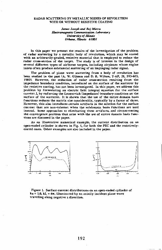
RADAR SCA TIERING BY METALLIC BODIES OF REVOLUTION WITH OR WITHOUT RESISTIVE COATING
Janu,s Joseph and Raj Miura B«:tromagnmc Comnum.ication Laboratory
Uni.versil.y of I1linois · Urbana. I1linois 6180 I
In this paper we present the results of the investigation of the problem of radar scattering by a metallic body of revolution. which may be coated with an arbitrarily-graded, resistive material that is employed to reduce the radar cross-section of the target. The study is of interest in the design of several different types of airborne targets, including airplanes whose engine inlets often produce substantial scattering of an impinging radar signal.
The problem of plane wave scattering from a body of revolution has been studied in the past (A. W. Glisson and D. R. Wilton, T-AP, 28, 593-603, 1980). However, the reduction of radar cross-section resulting from the impedance boundary condition, introduced on the surface of the scatterer by the resistive coating, has not been investigated. In this paper, we address this problem by formulating an electric field integral equation for the surface current J, by enforcing the Leontovich (impedance) boundary condition on the surface of the scatterer. It is shown that the use of the entire domain basis functions reduces the matrix size considerably, typically by a factor of three. However, this also introduces certain artifacts in the solution for the surface current that are non-existent when the subdomain basis functions are used instead. Some approaches to eliminating these artifacts, and circumventing the convergence problem that arise with the use of entire domain. basis functions are discussed in the paper.
As an illustrative numerical example, the current distribution on an open-ended cylinder is shown in Fig. 1, for both the PEC and the resistivelycoated cases. Other examples are also included in the paper.
Figure 1. Surface current distributions on an open-ended cylinder of ka = 1.0, kL = 41T, illuminated by an axially incident plane wave traveling along negative z direction.
192

MODAL ATTENUATION IN AN OVERMODED DIELECTRIC-COATED CIRCULAR WAVEGUIDE FOR RCS REDUCTION
R. Clu,u, C. S. Lee and S. W. J,,,., J-:Iectromagnaics /..a/x,ralory
lln.iversily of /lliru,is Urbana, //Jilu,is 61801
The radar cross section (RCS) of a circular waveguide terminated by a perfect electric conductor has been studied extensively because it can model many practical devices such as the jet intake of an airplane, missile, etc. It is known that the RCS can be significantly reduced if the PEC-terminated waveguide is coated with a lossy magnetic material and the frequency is low (a/A~l, a = radius of the waveguide and A = the free-space wavelength). But in many applications, the dimensions of the device are much larger than the wavelength, and the low-order modes (which are mostly responsible for the RCS near axial incidence in an overmoded waveguide coated with a lossy material) have small attenuation constants which decrease as a function of A2/al, Consequently, the RCS reduction of a waveguide coated with a single lossy layer is limited to small ranges of frequency and incident angle.
The purpose of this paper is to demonstrate that with a double layer of coating. the low-order modes can have very large attenuation constants over a broad range of frequency, even if the coating material is very lossy and the coating layer is thin. And, a larger RCS reduction is possible over a wider range of frequency and incident angle than in the single layer coating case.
With a double-layer of coating. the fields inside the waveguide can be more easily manipulated than with a single-layer. We have found that a lossy layer usually expels the fields as the frequency increases, and the attenuation constants become small. A lossless coating with high permeability or permittivity, however, attracts fields in an overmoded waveguide, but no attenuation is attained. Thus it is difficult to get high attenuation constants of the normal modes using a single layer of coating when a/A is large. On the other hand, a double layer of coating with a lossless layer near the waveguide wall and a lossy and magnetic layer towards the center of the cylinder results in large attenuation constants of the low-order normal modes over a broad range of a/A value. With application of this technique, it is possible to obtain large RCS reductions for a broad range of practical problems.
193
RADAR CROSS SECTION PREDICTION USING A HYBRID METHOD
C. F. Lee and R. T. Shin Department of Electrical Engineering and Computer Science
and Research Laboratory of Electronics Massachusetts Institute of Technology
Cambridge, Mass. 02139
The method of moments (MoM) is widely used to calculate the radar cross sections of arbitrarily-shaped objects. However, its application is limited to small objects due to large computation time required. A hybrid method which combines the MoM with the physical theory of diffraction (PTD) may be used to speed up the computation time and extend the applicability of MoM to electrically large objects. In the hybrid method, rather than directly inverting the impedance matrix, one -uses an iterative method to solve for the induced surface current with the approximate surface currents obtained using PTD. For flat plates, the physical optics and the edge diffraction currents are used. For cylindrical objects, physical optics current, creeping wave current, and approximate expression for the transition region current are used. The region over which MoM is applied may be the whole object or it may be limited to the regions where the PTD currents are not accurate. Iteration methods such as conjugate gradient and successive over-relaxation are used. It is shown that by using the approximate PTD currents, the iteration converges faster. Also, when calculating the RCS as a function of incident angle, it is shown that the iteration converges very fast if the current calculated for the previous angle of incidence is used as an initial guess. The convergence is even faster if the initial guess for the phase of the current is modified by the differences in the phases of the physical optics currents for the two angles of incidence. The theoretical results will be illustrated by calculating radar cross sections of large objects where conventional MoM cannot be applied and comparing with experimental data.
194
SALON 5/6 B-18-ELECTROMAGNETIC THEORY II
Chairman: R.J. King THURSDAY-AM
Page 8:30 CHAIRMAN'S REMARKS 8:40 The Application ol Group Theory to Arrays
H.N. Kritikos and J.E. Richie, The University of Pennsylvania.......................................... . . . 196
9:00 Diffraction ol Plane Waves Past a Series ol Absorbing Hall-Screens J. Walfisch and H.L. Bertoni, Polytechnic Institute of New York. . . . . . . . . . . . . . . . . . . . . . . . . . . . . . . . . . . . . . . . . . . . . . . . 197
9:20 Calculation ol the Surface Field at An Interior Resonance Point R.K. Ritt, Illinois State University ............................ 198
9:40 Approximate Analytic Continuation ol the Rayleigh Series Beyond Its Radius ol Convergence D.C. Power, Raytheon Co .................................... 199
10:00 COFFEE BREAK 1 0:20 Computer Program lor Plotting the Vector Fields
D. Kajfez and R.T. Ward, University of Mississippi ............. 200 10:40 A Time-Domain SEM View ol Coupling Coefficients
W.A. Davis, Virginia Poly Institute; D.J. Riley, Sandia National Labs. . . . . . . . . . . . . . . . . . . . . . . . . . . . . . . . . . . . . . . 201
11 :OD New Methods lor Quantification of Induced EM Fields in Finite Heterogenous Bodies H. Wang and K.M. Chen, Michigan State University ........... 202
11 :20 Assessment ol the Ability ol Blood Flow to Remove Heat from Tissue Irradiated by Radiolrequency Electromagnetic Radiation S.C. Li, Trenton State College; D.K. Cohoon, Temple University. . . . . . . . . . . . . . . . . . . . . . . . . . . . . . . . . . . . . . . . . . . 203
11 :40 Scattering by a Circular Cylinder with Translationally Invariant Anistropies N.J. Damaskos, H. Massoudi and J.C. Monzon, Damaskos, Inc.; P.L.E. Uslenghi, University of Illinois ......................... 204
195
THE APPLICATibN OF GROUP THEORY TO ARRAYS
Haralambos N. Kritikos James E. Richie
Department of Electrical Engineering Moore School of Electrical Engineering University of Pennsylvania Philadelphia, Pa.
Abstract group concepts can provide useful insight into the study of various electromagnetic applications involving £ymmetry, such as antenna arrays. The application of group theory to array geometries, however, has not been investigated.
Group theory has been extensively used in quantum mechanics to solve Shrodinger's equation. In solid state physics, energy band calculations for crystalline solids heavily depends on the point group symmetry of the crystal lattice.
In this paper, the point groups will be studied in the context of antenna arrays. Each group exhibits a character table which contains the irreducible representations of the elements of the group. The character table also admits a set of basis functions for the irreducible representations, which are orthogonal by the great orthogonality theorem. In summary, the character table contains all the information necessary to completely specify all the properties of a group.
The field pattern of each orthornormal basis function from a group can be calculated. The relative merits of each array geometry will be discussed by comparing the field patterns associated with each group.
196
DIFFRACTION OF PLANE WAVES PAST A
SERIES OF ABSORBING HALF-SCREENS
Joram Walfisch and Henry L. Bertoni Center for Advanced Technology in Telecommunications
Polytechnic Institute of New York Brooklyn, N.Y. 11201
In modeling UHF/microwave propagation in Urban environments, rows or blocks of buildings of nearly uniform height are replaced by parallel absorbing half-screens, whose separation is large compared to wavelength. Propagation is then veiwed as a process of multiple diffraction past a series of half-screens. Even though the buildings have irregularities on the order of the wavelength, the forward diffracted field retains phase coherence with the incident field. However, the back diffracted fields lose phase coherence, and are neglected.
This paper describes the computation of the fields resulting when a plane wave is diffracted by a series of absorbing half-screens whose edges are of uniform height. In our studies diffraction by as many as 130 half-screens has been considered. A Kirchhoff-Huygens integration is used to find the field in the plane of one half-screen due to the field propagating past the plane of the previous halfscreen, and the process is repeated in sequence for all screens. Choice of the integration rule, integration step size, integration aperture size and truncation strategy are discussed.
The field incident on the edqe of the Nth half-screen is computed as a function of N. - For a given finite glacing angle a, the field is found to settle to a limit value for N large enough. When ais small, the settled value is found to vary as a to the 0.9 power. For a=O, the field at the edges is found to vary as 1/v'N. Transverse variation of the settled field in the plane of the half-screen is found and interpreted in terms of simple refraction and diffraction processes.
197

CALCULATION OF THE SURFACE FIELD AT AN INTERIOR RESONANCE POINT
R.K.Ritt, Illinois State University, Normal IL 61761
It is known that many scattering problems, when represented as an integral equation on the surface of a bounded scatterer, can be characterized by the equation:
M(k)x(k) • y(k).
x(k) is the unknown surface field, y(k) is a known source field (at the surface), and M(k) is a known linear operator. It is further known that y(k) and M(k) are analytic for all k, and that M""l(k) is meromorphic whose real singularities occur at those values of k which correspond to interior resonances of the scatterer. It is also known that if k•ko is such a singularity, x(k) has a removable singularity at k•ko· However, the value of the surface field
Xo - l:lm k ... ko
x(k) • lim M""l(k)y(k) k- ko
is ,in general, not easily calculated, because of the poor conditioning of the matrix approx:lmation for M(k) for values of k close to ko•
We shall show that the problem of calculating Xo can be.reduced to the problem of inversion of a nonsingular operator, and that no l:lmits need be calculated.
For example, suppose M""l(k) has a pole of order one at k•ko, and M(k) and y(k) have the Taylor expansions:
M(k) •Mo+ (k-kci)M1 + ••• ; y(k) •Yo+ (k-ko)Y1 +· •••
Then if Z0 is the projection on the null space of the adjoint of Mo, and Xo • I - Z0 , then the operator
Mo,l • XoMo + ZoMl
is invertible, and
Xg • Mo.1 -l <Yo+ Zo11) •
In general, it is possible to find the form of the appropriate invertible operator without a priori knowledge of the order of the pole of M""l(k). However, in this case, it is required, at each stage of a recursive process, to test the operator which is obtained,for invertibility. The,process terminates at that step correspnding to theorder of the pole of M-1 (k).
198

APPROXIMATE ANALYTIC CONTINUATION OF THE RAYLEIGH SERIES BEYOND ITS RADIUS OF CONVERGENCE
Donald C. Power Raytheon Company
Missile Systems Division Hartwell Road
Bedford, Ma 01730
Pade approximants are used to approximately continue the Rayleigh series for the radar cross section of the sphere beyond its radius of convergence. Numerical studies show that accurate results for the RCS can be obtained to ka:::::2.2 if many series terms are available. Since this is rarely, if ever, the case, it is further demonstrated that even with as few as four nonvanishing terms available, the technique is accurate to ka i::z 1.3. This provides an indication of the number of series terms which must be calculated in order to use the Rayleigh series in the lower part of the resonance regime. An additional point that is demonstrated is the ability of the technique to provide highly accurate estimates of the radius of convergence of the series.
199
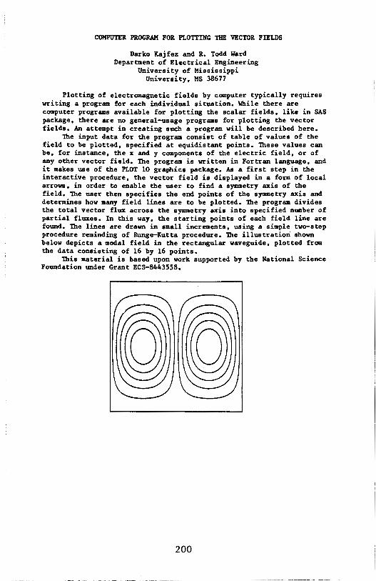
COMPUTER PROGRAM FOR PLOTTING 1llE VECTOR FmLDS
Darko Kajfez and R. Todd Ward Department of Electrical Engineering
University of Mississippi University, MS 38677
Plotting of electromagnetic fields by computer typically requires writing a program for each individual situation. While there are computer programs available for plotting the scalar fields, like in SAS package, there are no general-usage programs for plotting the vector fields. An attempt in creating such a program will be described here.
'nle input data for the program consist of table of values of the field to be plotted, specified at equidistant points. lbese values can be, for instance, the x and y components of the electric field, or of any other vector field. 'lbe program is written in Fortran language, and it makes use of the PLOT 10 graphics package. As a first step in the interactive procedure, the vector field is displayed in a form of local arrows, in order to enable the user to find a symmetry axis of the field. lbe user then specifies the end points of the symmetry axis and determines how many field lines are to be plotted. 'nle program divides the total vector flux across the symmetry axis into specified number of partial fluxes. In this way, the starting points of each field line are found. 'lbe lines are drawn in small increments, using a simple two-step procedure reminding of Runge-Kutta procedure. 'nle illustration shown below depicts a modal field in the rectangular waveguide, plotted from the data consisting of 16 by 16 points.
'Olis material is based upon work supported by the National Science Foundation under Grant ECS-8443558.
200
A TIME-D01AIN SEM VIEW OF COUPLING COEFFICIENTS
William A, Davis, Virginia Poly Inst and State University, Blacksburg, VA, and Douglas J, Riley, Sandia National Labs,
Albuquerque, NM
Since the mid-1970's, concern about coupling coefficients in the singularity expansion method <SEM) has been of interest to a number of researchers. A thorough discussion based on standard complex frequency domain approaches to SEM has been presented by Baum and Pearson tElectromagnetics, 1:2, 209, 19Bl),They found the coefficients could be defined by a number of classes which are equivalent analytically, but with possibly varying effects numerically, The latter is particularly true toward efficiency of the technique applied. This paper explores these questions for the time-domain approach to SEM computation.
This time-domain approach depends on solving the a transient difference equation for the poles of the scatterer. The particular difference form is identical to the phase canonical form found in control theory for multiple input-output relations. Once the poles are Known, the coupling coefficients may be obtained in an analogous manner to the frequency-domain approach, However, these coefficients become difference type, time convolutions, and taKe various forms depending on the particular expansion of the incident field during illumination. This is precisely the conclusion reached in the frequency-domain form from which one concludes analytic equivalence of the various classes of coefficients.
This paper will consider the simplest manner for developing the coupling coefficients in the time-domain with the resultant class-2 form. Variations also will be presented to gain insight into the other classes as obtained from a transient approach.
201
NEW METHODS FOR QUANTIFICATION OF INDUCED EM FIELDS IN FINITE HETEROGENOUS BODIES
H. Wang and K.M. Chen Department of Electrical Engineering and Systems Science
Michigan State University, E. Lansing, MI 48824
Some new methods to improve the numerical solution for the induced EM field in a finite body are investigated.
For the first method, we have modified the tensor integral equation method developed by Liversay and Chen with an equivalent magnetic surface current to improve accuracy of numerical results. In the numerical solution of the tensor integral equation, the pulse basis function expansion creates the discontinuity of E field at the boundary of adjacent cells. An equivalent magnetic surface current is introduced to compensate the discontinuity of the tangential component of E field at the boundary.
The second method uses an iterative loop-EMF method which is designed to calculate the E field of the magnetic mode induced by the incident magnetic field. Faraday's law is applied to each subdivided cell to relate EMF of the cell to the magnetic flux linkage. The system of linear equations for EMF's can be solved in terms of the H field in each cell. To start the iterative process, we use the incident magnetic field as the zeroth-order H field to solve for the zeroth-order EMF. From this EMF and the resulting induced current the first-order H field can be calculated. After that the first-order EMF can be determined. The iteration continues until both EMF and the H field converge.
Another new method utilizes the linear type functions of Serendipity family as the basis function to solve electric field integral equation. The advantage of this method is that it guarantees the continuity of the E field, in both normal and tangential components, between adjacent homogeneous cells.
202

',
ASSESSMENT OF THE ABILITY OF BLOOD FLOW TO REMOVE HEAT FROM TISSUE IRRADIATED BY
RADIOFREQUENCY ELECTROMAGNETIC RADIATION
Shu Chen Li Department of Mathematics
Trenton State College Trenton, New Jersey 08625
D. K. Cohoon Department of Mathematics
Temple University 03816 Philadelphia, Pennsylvania 19122
Using concepts of Cohoon and Burr (SAM-TR-82-2 of the USAF School of Aerospace Medicine in San Antonio, Texas 78235 and pp 452-560 of the IEEE Transactions on Biomedical Engineering, Volume BME-27, No. 8(1980)) we implemented in a computer program exact analytical formulas for the thermal response stimulated in a cylindrically symmetri.c layer of muscle surrounding a cylindrical column of blood by polarized time-harmonic, and planar electromagnetic waves with frequencies in the radiofrequency range •. The surfaces separating the regions of homogeneity or the above structure are cylinders with circular cross sections whose axis is either parallel to the electric vector of the incoming wave(a transverse magnetic TM exposure) or is parallel to the. magnetic vector of the incoming wave(a TE exposure). We first .use cylindrical harmonics to express the solution of Maxwell's equations at any point in the interior of the structure, use Poyntings theorem to get a radiative energy transfer term Qr at any point in the interior of the struc-ture: Hilbert space methods are used to get a precis,e analytic solution o.f the equation, pcft - div(K(grad(u)) (l/2) (al El 2/(4.l84xlo6)), where p, c, and Kare, respectively, the tissue density, specific heat, and conductivity in c.g.s. and a and E are the microwave conductivity and peak electric field strength, respectively in MKS units. We always assume that the blood is electromagnetically coupled to the simulated muscle material.and that tangential components of the E and H vectors are continuous across. the blood-muscle interface. However, by using different thermal coupling models we quantify the ability of blood to remove heat from irradiated tissue. Computer graphics were used to display the temperature increase u as a function of the radial coordinate for various times.
203
SCATrERING BY A CIRCUI.AR CYLENDER WI'lll TRANSLA'.fIONALLY INVARIANT ANISCJI'ROPIES
N. J. Damaskos, H. Massoudi, J.C. Monzon Damaskos, Inc., Concordville, PA 19331
and P.L.E. Uslenghi
Department of Electrical Engineering and Canputer Science University of Illinois, Chicago, IL 60680
A circular cylinder of axis z and radius f =bis made of a hanogeneous
lossy anisotropic material, and is surrounded by free space. With reference
to principal axes (x0
, y0
, z), both permittivity and permeability tensors
are diagonal. The incident field is a plane wave which propagates in a
direction~ perpendicular to the cylinder axis {~f~0
), and has arbitrary
polarization. we want to determine the total field inside the biaxial
cylinder and the scattered field in the surrounding free space.
The electranagnetic field inside the biaxial cylinder is the superposition of E-modes and H--roocles, whose transversal canponents are
obtained by first-order differentiation of the longitudinal canponents Ez'
Hz· In turn, Ez and Hz are written as Fourier series whose terms are
-products of radial eigenfunctions and azimuthal exponential functions. The
radial eigenfunctions satisfy differential-difference equations which become
Bessel's equation when the cylinder's material is electrically and
mcgnetically uniaxial.
The radial eigenfunctions may be written as finite integrals whose.
integrands are the products of known Bessel function, known exponentials,
and an unknown function; thus, the problem is reducted to finding two
unknown scalar functions of a single variable, one for E--roocles and one for
H-modes. Imposition of the boundary conditions at f = b means that each of
the two unknown functions satisfies a Fredholm integral equation of the
first kind, whose solution is discussed numerically.
The technique used herein may be considered as a particular case of a
more general approach to scattering by anisotropic cylinder, that is based on a plain-wave representation of the fields (J. c. Monzon and N. J.
Damaskos, "Two-dimensional scattering by a hanogeneous anisotropic rod", to be published) •
204
SALON 10 B-19-INVERSE SCATTERING 111 (Imaging and Signal Processing)
Chairman: A. Jordan THURSDAY-AM
Page 8:30 CHAIRMAN'S REMARKS 8:40 Discrimination of Scatterers Using Natural Resonance
Annihilation M.A. Morgan, Office of Naval Research, Electronics Division; J.B. Dunavin, Air Force Institute of Technology ....... 206
9:00 Super-Resolved Target Recognition and Classification Based on Models of Neural Networks N.H. Farhat and S. Miyahara, University of Pennsylvania ...... 207
9:20 Phase Gradient Data & Statistical Target Structure Estimation 8. Borden, R.J. Dinger and G. Hewer, Naval Weapons Center ............................................ 208
9:40 On The Tolerance of Microwave Images to Distortion in the Radiation Field B.D. Steinberg, Valley Forge Research Center, University of Pennsylvania .................................. 209
10:00 COFFEE BREAK 10:20 Passive, Airborne, Synthetic Holographic Imaging of Terrestrial
Features with Radio Waves G. Tricoles and R.A. Hayward, San Diego, California .......... 210
10:40 Superresolution in the Near Field C. Jin and B.D. Steinberg, Valley Forge Research Center, University of Pennsylvania .................................. 211
11:00 Application of Adaptive Beamforming to Aircraft Imaging S.H. Taheri, Valley Forge Research Center, University of Pennsylvania .................................. 212
11:20 Imaging of Objects Behind A Random Screen Using Partially-Coherent Radiation R.L. Fante, AVCO Systems Textron .......................... 213
11:40 Discrimination of Complex Radar Targets With E-Pulses and Single-Mode Extraction Signals K.M. Chen, D. Nyquist, E. Rothwell, W. Sun, N. Gharsallah, M. Blischke and 8. Drachman, Michigan State University ............................................ 214
205
DISCRIMINATION or SCATTERERS USING NATURAL RESONANCE ANNIHILATION
Michael A. Morgan Electronics Division
Office of Naval Research Arlington, VA 22217
Jaaes B. Dunavin Air Force Institute of Technology
Dayton, OH 45433
The use of aspect-invariant coaplex natural resonances for identification of scatterers has been a topic of intense research for over a decade. In addition to the paraaeter extraction aethods, such as that of Prony and its variants, a class of techniques has arisen which is based upon the annihilation of resonances in the received scattered signal. The "K-Pulse Concept" (Kennaugh, IEEE TraDs. AP-29, 3Z7-331, 1981) can be expanded to include a wide variety of convolutional filters for scatterer discriaination, as will be shown·.
In this effort, various signal processing strategies are investigated for the extinction of the natural resonance energy which appears in the "late-time" (undriven) portion of an iapulsively excited scattering response, (Morgan, IEEE TraDs. AP-32, 466-473, 1984). Approaches considered include FFT synthesis of analog differential operator filters as well as directly impleaented digital transverse convolution filters. Discriaination perforaance is tested for various levels of noisepollution on scattering signals. These tests are performed for synthetically constructed signals as well as for transient scattered responses obtained by both nuaerical aethods (integral equation) and time-domain measurements.
206
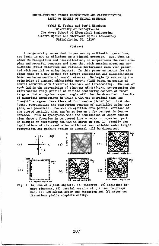
SUPER-RESOLVED TARGET RECOGNITION AND CLASSIFICATION BASED ON MODELS OF NEURAL NETWORKS
Nabil H. Farhat and Sunji Miyahara University of Pennsylvania
The Moore School of Electrical Engineering Electro-Optics and Microwave-Optics Laboratory
Philadelphia, PA 19104
Abstract
It is generally known that in performing arithmetic operations, the brain is not as efficient as a digital computer. But, when it comes to recognition and classification, it outperforms the most complex and powerful computer and does that with amazing speed and robustness (fault tolerance and reliable performance even when presented with partial or noisy inputs). In this paper we report for the first time on a new method for target recognition and classification based on known models of neural networks. We begin by reviewing the principles of content addlc.et>4able memoky (CAM) based on models of neural networks with iterative feedback and thresholding. The use of such CAM in the recognition of 4.lnogkam cla44i6i~, representing the differential range profile of visible scattering centers of radar targets plotted against aspect angle will then be described. Results of numerical simulations in which a CAM was exercised that was "taught" sinogram classifiers of four random planar point test objects, representing the scattering centers of simplified radar targets, are presented. Correct recognition from partial versions of the stored entities that can be as low as a few percent is demonstrated. This is synonymous with the realization of super-resolution where a function is recovered from a noisy or imperfect part. An example of exercising the CAM is shown in Fig. 1. Finally the implications of the results for efficient and reliable radar target recognition and machine vision in general will be discussed.
(a)
(d}
Fig.
+.data
I . . X . . . .
(b)
d1t1 I !O"r ,., e. e a9pect angle 2pi
l a n C •
dlltter i • Y 2
t a •• n C • I I ... t. t aspect an!f I e 2p i
i ' I t . . d •. data
(c). ~ •-.
(f}
I
t.t aspact •n!fl• 2pi d.,. lter i ' I f a • n C • I . . .. e.e Hpect an!fle 2pi
1. (a) one of 4 test objects, (b) sinogram, (c) digitized bi" nary sinogra~, (d} partial version of (c) used to prompt CAM, (e) CAM output after one iteration and (f} after two iterations yields complete entity.
207

PHASE GRADIENT DATA AND STATISTICAL TARGET STRUCTURE ESTIMATION
B, Borden, R, J, Dinger, and G, Hewer Research Department, Physics Division, Code 3814
Naval Weapons Center, China Lake, CA 93555
Asymptotic inverse scattering has long been able to reconstruct the uniform convex surfaces from which a sufficiently large amount of scattering data have been collected, However, realistic targets are not usually uniform, not strictly convex, and rarely can the scattering data be obtained from all aspects, Under these restrictions, geometrical optics methods are unable to separate the effects of varying target reflectivity coefficients from local curvature effects, and deterministic surface recoverability is not usually possible, By using a small amount of relative phase information instead of pure amplitude data, these considerations can be modified,
Phase gradient data have long been used in target tracking systems. The statistics of the error vector in these tracking situations are well understood; under very general assumptions about the statistical properties of a very complex target, it can be shown that the error depends on gross target structure parameters and not on local reflectivity, By using this fact coupled with maximum likelihood estimation techiques, a statistical structure estimation scheme has been devised that
1) Ignores the complications created by local morphology, 2) Requires only high frequency data collected over a very
narrow set of aspects, 3) Allows for gross structure parameter estimation,
With some .! priori information added, it is believed that these kinds of properties may make for a general target classification technique,
We review the statistics of the scattering process, discuss the estimation technique, and show how it can be applied to scattering data,
208
ON THE TOLERANCE OF MICROWAVE IMAGES TO DISTORTION IN THE RADIATION FIELD
Bernard D. Steinberg Valley Forge Research Center
The Moore School of Electrical Engineering University of Pennsylvania
Philadelphia, PA 19104
Microwave images are highly tolerant to certain types of
1. Distortions in the radiation field, 2. Errors in measurement of the radiation field, 3. Circuit and system errors in the Butler matrix or digital
beamformer.
The phenomenon is demonstrated with microwave images of outdoor scenes at distances of 50 m to 10 km. The resolution in these images is very fine, typically 1-3 m both in range and cross range. Images are compared for various amounts of amplitude and phase distortion of the measurements of the radiation field, as well as errors in the image-forming process.
A theory is presented to account for the observations.
The research was supported by the Army Research Office and the Office of Naval Research.
209
PASSIVE, AIRBORNE, SYNTHETIC HOLOGRAPHIC IMAGING OF TERRESTRIAL FEATURES WITH RADIO WAVES
G. Tricoles 6144 Lourdes Terrace, San Diego, CA 92120
and R. A. Hayward
6730 Amberly Str., San Diego, CA 92120
In attempting to locate and display surface traces of geological faults we utilized holograms that were formed by an airborne receiver of radio waves broadcast by commercial stations.
The wave propagation mechanism is apparently a vertically polarized ground wave which is scattered by structures on the Earth's surface. The receiving antenna received both horizontally and vertically polarized waves.
One dimensional, line holograms were formed by recording received real-vaTued intensity during aircraft motion. The holograms are interference patterns, apparently resulting from interference of the scattered and illuminating waves.
Images were computed from a hologram by first multiplying the measured data by a quadratic lens function and then Fourier transforming the product. Actually, pairs of images were formed, one on each side of the line hologram. To resolve the ambiguity, images from distinct holograms were multiplied. Resolution was improved by multiplying images from up to four holograms.
Although image quality was well below that from microwave synthetic aperture radars, the images produced by the new technique display the locations of a surface trace of a fault. In addition ponds, buildings and other terrain features were displayed.
210

SUPERRESDLUTIDN IN THE NEAR FIELD
Chaalun Jin and B.D. Steinberg Vallay Farge Research Center
Th• Nacre Schaal cf Electrical Engineering Univarsity cf Pennsylvania
Philadalphia, PA 19104
In recent years, nonlinear spectral analysis has bacama a subject cf growing interest in the field cf phased array signal precessing. The major reason far the interest is the potential far superresalutian beyond conventional methods, such as tha Black-Tukey method cf astimatian cf spectra. Twa popular methods cf nonlinear spactral estimation which have demonstrated a cansidarabl• increase in resalutian are Maximum Likalihaad Estimation by Capan and the Maximum Entropy Mathad by Burg which has been designated the autaragressiva method.
Th••• methods as well as many ethers suffer fram baing unable ta resolve coherent targets er sources. A racant contribution by Ajay Luthra cf the University cf Pannsylvania salves this problem. We call it Luthra·s mathad (LM>. LM takes a direct approach ta the problem cf obtaining the weights far the all-pale model fram the maasurad field samples.
The paper discusses tests cf LM an near-field microwave image data obtained fram the Valley Farge Resaarch Center <VFRC>. This method, as well as ether suparrasalutian techniques, are normally applicable anly ta paint targets in the far field. Image data obtained from VFRC are generally in the near field. Performing an experimental test cf LM on real data requires modifications ta LM ta make it fit the near-field situation. In this study, bath adaptive beamfarming, which has been very successful in high microwave imaging with the Valley Farge radiacamera, and Fresnel-term carractian are tested and compared.
211
APPLICATION OF ADAPTIVE BEAMFORMING TO AIRCRAFT IMAGING
s. Hassan Taheri Valley Forge Research Center
The Moore School of Electrical Engineering University of Pennsylvania
Philadelphia, PA 19104
ABSTRACT
Imaging of aircraft using sequential target returns as the aircraft moves along a-curvilinear path is considered. The equivalence of differential Doppler processing and the equivalent synthetic aperture radar are pointed out, and advantages of the latter technique are discussed.
With reference to actual measured data, adaptive beamforming techniques as used in the Valley Forge Radio Camera systems are shown to yield superior images. In addition, this approach to processing relaxes the stringent requirements on the trajectory estimation and gross Doppler removal procedure that exists in differential Doppler processing.
212

IMAGING OF OBJECTS BEHIND A RANDOM SCREEN USING PARTIALLY
COHERENT RADIATION
Ronald L. Fante Avco Systems Textron Wilmington, MA 01887
In this paper we will consider the imaging of an object located an arbitrary distance behind a random phase screen, for the cases when the object has an arbitrary state of surface roughness and the incident radiation has an arbitrary degree of spatial coherence. Detailed results will be presented for the limits of smooth and diffuse objects illuminated by. short-wavelength radiation that is either spatially incoherent or spatially coherent.
213

DISCRIMINATION OF COMPLEX RADAR TARGETS WITH E-PULSES AND SINGLE-MODE EXTRACTION SIGNALS
K.M. Chen, D.P. Nyquist, E. Rothwell, W.M. Sun, N. Gharsallah M. Blischke and B. Drachman*
Dept. of Elect. Engr. & Sys. Sci., Dept. of Mathematics* Michigan State University, East Lansing, Michigan 48824
Complex radar targets can be discriminated by convolving their radar returns with their synthesized, aspect independent, discriminant signals that include Extinction-pulse (E-pulse) and single-mode extraction signals. When the discriminant signals of an expected target are convolved numerically with the radar return of that target, the convolved outputs give zero or singlemode responses in the late-time period. When the discriminant signals of the expected target are convolved with the radar return from a different target, the resulting signals will be significantly different from the expected zero or single-mode responses, thus, the differing target can be aiscriminated.
The discriminant signals of a target are synthesized on the basis of natural frequencies of the target. Since the natural frequencies of a complex target are very difficult, if not impossible, to be determined theoretically, they are extracted from the pulse response of its scale model measured in the laboratory with the application of some theoretical methods developed by our group. After the natural frequencies of the complex target are determined, the E-pulse and the single-mode extraction signals of the target can be synthesized. These discriminant signals are then used to convolve with the pulse responses of the target measured at various aspect angles. The convolved results have demonstrated the capability of the scheme to discriminate between complex targets at any aspect angle.
For the purpose of demonstration, two complex targets, scale models of McDonnel-Douglas F-18 airplane and Boing 707 airplane which have similar sizes but different geometries, are used.
This research was supported by Naval Air Systems Command under Contract N00019-85-C-0411.
214
WYNDHAM B B-20-ARRAYS AND REFLECTORS
Chairman: R.M. Bevensee THURSDAY-PM
Page
1:30 CHAIRMAN'S REMARKS 1:40 Diversity Techniques for Sidelobe Reduction in Phased
Array Antennas H.M. Subbaram and B.D. Steinberg, University of Pennsylvania ............................................. 216
2:00 Method of Moments (NEC) Model of a Wideband Array of Printed Dipoles P. Elliot and A. Bucceri, Sperry Corporation ................... 217
2:20 Negative Input Resistance Calculated for the Center Element of a Broadside Array P. Elliot and D. Lamensdorf, Sperry Corporation ............... 218
2:40 Analysis of Two-Dimensional Lossy Radomes of Arbitrary Cross Section With or Without Reflectors E. Arvas, Rochester Institute of Technology; T.K. Sarkar, Syracuse University ......................................... 219
3:00 COFFEE BREAK 3:20 A Numerical Technique to Handle Reflector Surface Tolerance
Y.P. Loh, General Electric Space Division ..................... 220
3:40 Dual Shaped Subreflectors For Receiver Feed Systems H. Foltz, The University of Texas ............................ 221
4:00 RF-Transparent Structures for Feed Support in Spacecraft Antennas R.D. Graglia and M. Orefice, Politecnio di Torino, Torino, Italy ................................................ 222
215

DIVERSITY TECHNIQUES FOR SIDELOBE REDUCTION IN PHASED ARRAY ANTENNAS
H.M.Subbaram and B.D. Steinberg Valley Forge Research Center
Th• Moore School of Electrical Engineering University of Pennsylvania
Philadalphia, PA 19104
Transmitter location and frequency diversity will ba employed to drastically reduce the side radiation pattern of phased arrays in the following manner. The transmitters, located both inside and outside the racaiving array, illuminate the field of view in sequence. Each transmitter also hops over a set of frequencias having a narrow bandwidth. The returns from all the transmissions are then combined coherently to image the field of view. A frequency diversity technique developed previously <B.D.Steinberg and E.H.Attia, IEEE Trans. Ant. and Prop., vol. 31, Nov. 1983) incoherently recombinad the radiation field from each transmission to estimate the image. This technique required a large bandwidth in order to effectively suppress the side radiation pattern of the synthesized array.
It will be shown that coherent recombination of the received signals from each transmission <i> changes the receiver location (in wavelength units> each time a different frequency is transmitted, and (ii) adds the transmitter location to the receiver location in the karnal of the Fourier or Fresnel transform that is employed to image the field of view. Therefore, a MKN alement array can be synthesized from an N element receiving array by hopping aver a set of M different fraquencies transmitted sequentially from each of K different locations. Thus, the peak and average sidelobe leval of the synthesized array are about 1/MK times smaller than those of the initial thinned aperiodic receiving array. Further, we show that the length of the synthesized array is the sum of the lengths of the transmitting and receiving arrays; therefore the resolving power of the system can also be improved by using transmitter location diversity.
216

METHOD OF MOMENTS (NEC) MODEL OF A WIDEBAND ARRAY OF PRINTED DIPOLES
P. Elliot Sperry ~orporation Waltham, Massachusetts 02154
A. Bucceri Sperry Corporation Great Neck, New York 10020
The scattering parameters (s1,1) of a 5x5 planar array of strip dipoles have been calcula~ed using the Numerical Electromagnetics Code - Method of Moments (NEC-MOM). The results of this model were compared with measurements on a lOxlO array. The' close comparison demonstrates the viability of using a wire grid to model strip dipoles,· and of using the impedance properties of a small array of wideband radiators to predict the performance of a large array.
Electrically wide, planar dipoles were modeled using a grid of wires with about 20 wire segments per dipole. The width of the strip for each dipole was chosen to be .12 wavelengths at the center of the octave band of interest. The matching feed network and the source or terminating network at the driving point of each dipole was included in the model. The number of dipoles in the array was limited by the computer run time for a large number of wire grid segments.
Close agreement is demonstrated between the measured and calculated results, despite the difference in number of dipoles that comprise the arrays. The S1 i parameters between the center element of the array a~a other elements were accurately predicted. The sum of these S parameters yielded the active reflection coefficient of the center element, which was compared with the measured results and the grating lobe series calculation for an infinite array.
217

NEGATIVE INPUT RESISTANCE CALCULATED FOR THE CENTER ELEMENT OF A BROADSIDE ARRAY P. Elliot, D. Lamensdorf Sperry Corporation, 1601 Trapelo Road, Waltham, Massachusetts 02154
A negative active input resistance (or an active reflection coefficient greater than one, also known as scan blindness) was found to occur in the broadside direction for the central radiators of a finite, two-dimensional array of dipoles. This effect has previously been described only for phased arrays when scanned off broadside (e.g., R.C. Hansen, "Microwave Scanning Antennas" v. II, p. 340). The negative resistance was observed using a computer model for dipole arrays. The Numerical Electromagnetic Code - Method of Moments (NEC-MOM) used to model the arrays has been shown to accurately predict the input parameters and coupling for arrays of dipoles.
The real part of the mutual coupling between dipoles can be negative over a narrow band of frequencies (R.S. Elliott, "Antenna Theory and Design", p. 333). The cumulative effect of this negative mutual coupling by several dipoles surrounding a central one is to create a negative input resistance at that dipole. Fower is being coupled into the dipole with the negative input resistance from the other dipoles in the array. The total power radiated by the array is still positive, however.
The broadside array configurations which yielded a negative resistance were excited in the "forced" mode described by Hansen (v. II, P• 211). This excitation assumes an ideal voltage source with zero internal impedance driving each element of the array. This situation is approximated when distributed solid state sources with a very low internal impedance are used to excite the array. Several array configurations illustrate the phenomenon and how it ~an be overcome or avoided.
218

ANALYSIS OF TWO-DIMENSIONAL LOSSY RADOMES OF ARBITRARY CROSS SECTION WITH OR WITHOUT REFLECTORS
ErcUl'lent Arvas P-ochester Institute of Technology
Rochester, NY 14623
Tapan K. Sarkar Syracuse University Syracuse, NY 13210
A simple mo~ent solution is given for the problem of the electromagnetic transmission through two dimensional radomes of arbitrary cross section. -The radome is composed of one or more layers of lossy dielectric shells of arbitrary cross sections The reflectors consist of conducting strips next to the outer surface of the radorne • The eauivalence principle is used to replace the surfaces of the radorne and the strips by eauivalent electric and magnetic currents. The boundary conditions on the tangential component of the total electric field yields a set of coupled integral equations for the eauivalent currents. The integral eauations are solved by the method ·of moments with pulse expansion and point-matching techniaue. The effects of the surface-wave excitation and the interaction among the various portions of the dielectrics and the reflecting strips are automatically included in this solution. Computed results are the equivalent surface currents, the near field and the far field. The computed results are in very ~cod agreement with whatever published data available. The figure below shows a two dimensional Von Karr,an shape radome backed by a reflecting strip.
l
L•2..2 ,\ D•l.2. ~. l• 0.1 i\, f.~4.0 la,,li:o.1
219
A NUMERICAL TECHNIQUE TO HANDLE REFLECTOR SURFACE TOLERANCE
Y,P, LOH GENERAL ELECTRIC COMPANY, SPACE DIVISION
The surface tolerance effect of a reflector system has been modelled and represented by two factors: the surface phase factor (SPF>, and the surface normal fact.or <SNFl, SPF ac·counts for the optical path perturbation due to the uncertainty of the reflector surface location. The uncertainty of the direction of the surface normal vector is accounted for by the factor SNF,
The SPF and SNF of a parabolic reflector have been implemented and the gain degradation has been computed versus the surface tolerance. The results showed excellent agreement with the prediction based on Ruze's formula (Jhon Ruze,"Antenna Tolerance Theory- A Review",Proc, IEEE,Vol,5,No,4,April 1966,pp,633-640),
The advantages of the numerical approach to handle reflector surface tolerance effect include,
1, The effects of surface tolerance on cross-polarization may be easily obtained,
2, Reflector shapes other than parabolic, or tolerance other than Gaussian, can be handled with ease.
3, For surface tolerances caused by deterministic function of cyclic nature, such as thermal effect and mechanical vibration, the numerical approach provides a key to the solution of those problems.
The derivations of SPF and SNF for various cases and implementation considerations are described. Also, examples are included to illustrate the utility of this work.
220
DUAL SHAPED SUBREFLECTORS FOR RECEIVER FEED SYSTEMS
Heinrich Foltz Electrical Engineering Research Laboratory
The University of Texas at Austin
In high performance reflector antenna feed systems, careful attention must be given to the spillover, illumination, phase, and blocking efficiencies. Efficiency improvement is possible with special multimode feed horns of dielectric feeds, but for broadband applications and at millimeter wavelengths shaped subreflectors in combination with conventional feeds may be preferable.
This paper describes the design and testing of dual shaped subreflectors (DSS) for the Texas 5-m radio telescope. The subreflectors are arranged in a folded Gregorian configuration. They were synthesized using geometric optics. The synthesis procedure is related to that of Galindo and Mittra but has been simplified so that only a single differential equation needs to be solved and exact solutions are guaranteed.
Experimental results shows agreement with the design objectives. These objectives included more uniform aperture illumination, less illumination of the central blocked region and reduced spillover for the DSS as compared to conventional feeds. Presently DSS systems are being designed to improve coupling from quasi-optics receiver front-ends to open-sturcture mixers in sub-millimeter receivers, and to match the front-ends to the primary reflector. These systems should offer higher aperture efficiencies and reduced noise temperatures.
221
RF~TRANSPARENT STRUCTURES FOR FEED SUPPORT IN SPACECRAFT ANTENNAS
R.D.Graglia, M.Orefice Dipartimento di Elettronica, Politecnico di Torino
C.Duca degli Abruzzi 24, 10129 Torino, Italy
The increasing number of services to be provided by modern spacecrafts often requires several antennas and an efficient use of the payload platform area. In such cases, the support structures of feeds and/or subreflectors may intercept and distort the RF field radiated by some antenna on the spacecraft. It is therefore impor~ tant to assess design criteria in order to minimize these effects, and to obtain a maximum transparency of the support structures.
In order to have structures with good weight and mechanical characteristics, the use of advanced composite materials, i.e. fibre reinw forced plastics, is almost mandatory, in particular of those with good dielectric properties, as glass fibre or aramid fibre (kevlar).
The center fed reflector is the typical case where the scattering of the feed (or subreflector) supporting structure is very important: support struts have generally metallic characteristics, and their effects are generally studied with various existing methods for the analysis of the blocking of struts and obstacles. Conversely, if the structure is made of penetrable (dielectric) material, its analysis is more complex.
The feed (or subreflector) support may consist of planar or locally planar structures (e.g. a large cone or cylinder surrounding the suM breflector, or a pyramidal tower), or of small cylindrical structures (e.g. a tripod, or a truss).
In the planar case, a theoretical approach is relatively easy, by using the transmission line equivalence and computing the reflection and lransmission coefficients. Typical structures are sandwich, thin or 'thick sheet: for each of these types design guidelines will be presented, which allow to design them in order to obtain satisfactory transparency characteristics for a given frequency or incidence angle. Diffraction effects of the edges have then to be taken into account.
Structures made with small cylindrical elements require a complex analysis, except when dealing with circular cross section and ne~ glecting mutual interaction among the various members. A detailed analysis with Moment Method technique for various cross section con~ figurations has been carried out, and also in this case design criteria will be presented.
Measurements have been done in order to verify the theoretical prediction of transmission and reflection performance. Tests have been made both in free space and in waveguide, showing good agreement with computed values.
222
PHILA. NORTH B-21-SPECIAL SESSION ON NUMERICAL METHODS
Chairman: C. Butler THURSDAY-PM
Page
1:30 CHAIRMAN'S REMARKS 1:40 The Method of Moments in Electromagnetics
R. F. Harrington, Syracuse University ......................... 224 2:00 An Overview of Time-Domain Integral-Equation Models in
Electromagnetics E.K. Miller, The University of Kansas ......................... 225
2:20 The Finite Difference Time-Domain (FD-TD) Method for Electromagnetic Scattering & Interaction Problems A. Taflove, Northwestern University; K. Umashankar, University of Illinois ........................................ 226
2:40 Finite Element Methods in EM Computations K. K. Mei, University of California, Berkeley ................... 227
3:00 COFFEE BREAK 3:20 Application of the Generalized Conjugate Gradient Method for Iha
Solution of EM Field Problems T.K. Sarkar, Syracuse University ............................. 228
3:40 A Hybrid-Iterative Mathod for Scattering Problems G.A. Thiele, University of Dayton ............................ 229
4:00 On Some Iterative Approaches to Solving a Class of Electromagnetic Scattering Problems R. Mittra and C.H. Chan, University of Illinois ................ 230
4:20 Summary and Discussion C. Butler, Clemson University
223
THE METHOD OF MOMENTS IN ELECTROMAGNETICS
Roger F. Harrington Department of Electrical Engineering
Syracuse University Syracuse, NY 13210
The method of moments is a generic name given to projective methods in which a functional equation in an infinite dimensional function space is approximated by a matrix equation in a finite dimensional subspace. Any projective method can be put into the language and notation of the method of moments, hence the concept is very general. Any linear field problem can be formulated either by differential equations (Maxwell's equations plus boundary conditions) or by integral equations (Green's functions plus superposition). Furthermore, neither the differential formulation nor the integral formulation for any particular problem is unique.
Differential formulations plus the method of moments can be used to obtain the finite-difference and the finite-element methods. Such methods are usually characterized by large, sparse matrices. Special solution techniques, such as iterative methods, are often used to handle the large matrices. These methods, and their advantages and disadvantages, will be discussed by other speakers.
Integral formulations plus the method of moments are what most of us think of when discussing the method of moments. One of the simplest electromagnetic applications is to wire antennas and wire scatterers. More difficult applications are to conducting bodies of arbitrary shape, and to dielectric bodies. All of these problems can be discussed in terms of generalized network parameters, a name given to the resultant matrices. Some advantages of the integral formulation over the differential formulation are: (1) The unknown is a one or two-dimensional current instead of a threedimensional field. (2) The boundary conditions at infinity are incorporated into the solution via the Green's function. (3) The inverse of the moment matrix gives, by a matrix multiplication, the current distribution for any field excitation. A disadvantage of the int~gral formulation over the differential formulation is that it is more difficult to treat complicated geometries and media inhomogeneities. A disadvantage of the integral formulation over the Geometric Theory of Diffraction is that the wire or body size is limited by the size of the matrix that can be handled. In practice, for wire problems one is usually restricted to arbitrary wires tens of wavelengths long, while for bodies, one is usually restricted to arbitrary surfaces a few square wavelengths in area. These restrictions could be removed by judicious choice of expansion and testing functions, but this is difficult to do. The ultimate limitations to the method are set by the ingenuity of the investigator in formulating the solution, and by the size and speed of the computers available.
224
AN OVERVIEW OF TIME-DOMAIN INTEGRAL-EQUATION MODELS IN
ELECTROMAGNET I CS
E. K. MIiier Department of Electrical and Computer Engtneertng
Nichols Hall. The Untverstty of Kansas Lawrence. KA 66045-2969
Computational electromagnetlcs embraces a wide variety of formulations and numerical procedures. The basic features which distinguish among the various approaches that might be chosen for linear problems Is how the fields are propagated spatially and how they are varied temporally. Spatially, fields can be propagated using Green's functions, modal expansions, rays and the basic Maxwell curl equations. Temporally their time variation may be either harmonic as In the frequency-domain, or Impulsive as In the time-domain. Given the number of permutations that can arise from the choices available, It Is not surprising that many different approaches have been developed that can provide essentallly equivalent Information.
In this paper, we examine the specific approach of using a time-domain Integral-equation (TDIE). The basic formulation wlll be outlined and Illustrated by application to a simple problem to Illustrate Its salient features. Its advantages, limitations, and computational characteristics wlll be summarized In terms of the problem types to which It Is applicable, the kinds of Information which It can provide, and compter storage and running time required. Our goal Is to characterize models using the TDIE and to put the approach Into perspective relative to other tools of compuatlonal e lecttromagnet !cs.
225
THE FINITE-DIFFERENCE TIME-DOMAIN (FD-TD) METHOD FOR ELECTROMAGNETIC SCATTERING AND INTERACTION PROBLEMS
Allen Taflove EECS Department, Northwestern University
Evanston, IL 60201
Korada Umashankar EECS Department, University of Illinois at Chicago
Chicago, IL 60660
The finite-difference time-domain (FD-TD) method involves a direct solution of Maxwell's time-dependent curl equations without resorting to formulation of potentials. Simple central-difference approximations for the required space and time derivatives are used to achieve a sampled-data reduction of the continuous electromagnetic field in a volume of space, over a period of time. Space and time di screti zati ons are se 1 ected to bound errors i nvo 1 ved in the sampling process, and to insure numerical stability of the algorithm. E and H field components are interleaved in space to permit a natural satisfaction of tangential field continuity conditions at media interfaces. The resulting system of equations for the fields is fully explicit, so that there is no need to set up or solve a set of linear equations, and the required computer storage is proporti ona 1 to the e 1 ectri ca 1 size of the volume modeled.
This paper reviews the formulation of the FD-TD method, and briefly reviews recent applications in modeling radar cross section, coupling through thin slots and to multi conductor cables, and inverse scattering in one and two dimensions. To enhance understanding, the application of FD-TD to a simple two-dimensional forward scattering problem will be covered in more detail. ·
FD-TD has a number of strong points, including ability to achieve highly detailed models, a dimensionally-low computer resource requirement for such prob 1 ems, abi 1 i ty to take advantage of modern vectorizing and multiprocessing computer architectures, and ability to interface with other detailed approaches such as the method of moments (MOM). The limitations of FD-TD include the need to re-run a problem when the incident wave angle is changed, and the dispersive effect of the discrete space 1 atti ce upon pulse propagation. Both strong points and limitations of FD-TD are discussed.
This paper concludes with a discussion of what types of problems FD-TD is suited for, and why. Factors such as availability of supercomputer time are. included in the discussion. Research horizons such as incorporation of conformal curved surfaces, large-scale multiprocessing, and single-point far-field reconstruction of scattering shapes are summarized as time permits.
226

Finite Element Methods in EM Computations*
K. K. Mei
Department of Electrical Engineering and Computer Sciences and the Electronics Research Laboratory
University of California, Berkeley, CA 94720
Abstract
Frequency domain electromagnetic computations using finite element
methods have been applied in hybrid with integral equations and with
harmonic expansion methods, starting in 1972. The harmonic expansion
method has since solved scattering by bodies of revolution, two bodies
of revolution, and by buried and partly buried bodies of revolution.
It is evident that the success of the harmonic expansion method is the
consequence of its ability to take advance of axial symmetry. For an
arbitrary 3-D problem the expansion method is just as clumsy as other
methods, so no progress has been made. Time domain finite element is
quite a different story. There is evidence that it can solve 3-D
problems with greater ease than other methods. Results will be shown.
*Research sponsored by U.S. Army Research Office Contract DAAG29-84-K-0067 and the Office of Naval Research Contract N00014-84-K-0272.
227
APPLICATION or THE GENERALIZED CONJUGATE GRADIENT METHOD
FOR THE SOLUTION or ELECTROMAGNETIC FIELD PROBLEMS
Tapan K. Sarkar Department of Electrical Engineering
Syracuse University Syracuse; New York 13244-1240
( 315) 423 - 3775
ABSTRACT: For a nonhermitian operator A, the conjugate gradient method solves the normal equations
A*AX • A*Y, instead of solving the operator equation AX• Y directly. Here A* denotes the adjoint operator. It is demonstrated that the conjugate gradient method is numerically very stable in the solution of highly illconditioned systems of equations (condition number 10**30) and also for the solution of extremely large systems of equations ( 16000 unknowns).
Even though in the actual computations A*A is never formed, however the condition number of the original operator equation is squared in the solution of A*AX • A*Y. In this presentation the original conjugate gradient method is reviewed. Also an extension of the original conjugate gradient method is presented which solves AX• Y directly without solving A*AX • A*Y. Hence the new method (henceforth termed as the generalized conjugate gradient method) is roughly three to seven times faster than the original conjugate gradient method desribed in IEEE Trans on Ant. and Propagat. Oct 1985 •
. i Numerical results are presented to illustrate the efficiency of the new method over the conventional conjugate gradient methods. It is also shown how the utilization of the fft can further reduce the computation time. Finally it will be illustrated as how to solve radiation and scattering from straight wire antenna problems in the order of N steps as oppposed to N squared steps taken by conventional matrix methods.
228
A HYBRID-ITERATIVE METHOD FOR SCATTERING PROBLEMS
Gary A. Thiele, Ph.D. Graduate Engineering and Research
University of Dayton Dayton, Ohio 45469
A new technique, named a hybrid-iterative method (HIM), is presented which computes the induced currents on an arbitrary, perfectly conducting scatterer. The technique is an evolution from two previous techniques developed earlier. The first of the previous techniques used the moment method to compute correction currents to an optics-type current. The second of the previous techniques effected a significant improvement by eliminating the use of the moment method to obtain the correction currents, using iteration to obtain them.
The technique described here incorporates the edge diffraction theory and the Fock theory into the ansatz of the iterative scheme. This procedure speeds up the algorithm as well as extending the range of problems that can be solved by the iterative scheme. Furthermore, the technique described in this paper incorporates the correction currents into the optics currents thereby substantially reducing the computation time. For intermediate size and larger bodies, the CPU time is significantly less than that of the moment method. We list the following important points:
1) Incorporating edge diffraction theory and Fock theory eliminates the need for computing higher-order correction currents. That is, speed of convergence is improved. Frequently, zeroth-order optics currents themselves furnish sufficiently accurate solutions. CPU time requirements are, therefore, less demanding,
ii) As the size of the closed body is increased our technique is computationally more efficient than method of moments, As an example, our technique requires only onethird to one-quarter the CPU time required by the MM to compute the currents on a 3,7A square cylinder, For larger scatterers, the advantage in CPU time is increasingly higher,
iii) Even though the technique has been demonstrated only for 2-D, perfectly-conducting scatterers, it may be extended to more complicated structures like coate"d scatterers and 3-D bodies,
Results are presented for a variety of curved and edged two-dimensional cylinders,
229
ON SOME ITERATIVE APPROACHES TO SOLVING A CLASS OF ELECI'ROMAGNETIC SCATTERING PROBLEMS
R. Miara and C.H. Chan. El«tromagnetic Communication LaboraJ.ory
University of I11inais Urbana, I11inais 61801
The purpose of this paper is to discuss three iterative approaches for solving electromagnetic scattering problems that provide alternatives to the widely-used Conjugate Gradient Method (CGM) of iteration. While the CGM approach has several theoretical and numerical attributes that make it a versatile and valuable tool for many problems of interest. there are situations involving a wide class of electromagnetic problems where it exhibits certain limitations that must be overcome before its application to these problems can be regarded as practical. Specifically, these limitations are: (i) slowness of convergence; (ii) non-convergence due to an ill-conditioned nature of the operator and build-up of round-off error; and, (iii) inability to treat multiple incident .:fields in a simultaneous and numerically efficient manner.
In this paper we discuss some concepts for enhancing the convergence of the iteration procedure by choosing certain directions for the basis vectors that are different from those prescribed by the conjugate gradient method. We also present some approaches to preconditioning the operator that attempts to modify the eigenvalue spectrum of the operator and, hence, improves its condition number. Finally, we present an iterative technique that employs a set of prechosen basis functions (in contrast to those recursively generated by following the CGM procedure), and is well-suited for solving the multiple r.h.s. problem. Numerical examples illustrating the use of these algorithms are included in the paper. ·
230
SALON 3/4 B-22-ELECTROMAGNETIC THEORY Ill
Chairman: D.L. Sengupta THURSDAY-PM
Page
1:30 CHAIRMAN'S REMARKS 1:40 Steady & Shock Currents Induced by ELF-LF Electric Fields
in Human Bodies & Metallic Objects C.J. Lin, University of Detroit; H. R. Chuang and K.M. Chen, Michigan State University ........................ 232
2:00 The Monopole on a Finite Ground Plane H. Bach and J.H. Lemanczyk, Technical University of Denmark ................................................... 233
2:20 Measurement & Characterization of Thin Slot Interior Coupling A.J. Ludwigsen, H.G. Hudson, R.J. King and K.S. Kunz, Lawrence Livermore National Lab ............................ 234
2:40 An Offset Grid System for Sampling Accuracy Improvement Y. P. Loh, General Electric Company .......................... 235
3:00 COFFEE BREAK 3:20 An Approximate Method for Incorporating the Wall Thickness
into Aperture Calculations G.A. Seely, Sandia National Labs ............................ 236
3:40 General Numerical Procedure for Conception of Metallic & Dielectric Large Bandwidth Horns C. Brochard, J.P.Martinaud and J. Toumeur, Thomson-CSF ..... 237
4:00 Convergence of Numerical Techniques for Electromagnetic Scattering J.S. Yu, Sandia National Laboratories; J.W. Williams, Booz, Allen & Hamilton, Inc ................ ,,_ ...................... 238
4:20 Clustering, Surface Perturbation and Material Effects on Absorption & Scattering by Rayleigh Particles H. Weil, The University of Michigan .......................... 239
4:40 The Error Estimate of EBCM Guo Yingjie Mao Yukuan, Northwest Telecommunication Engineering Institute, China ................................. 240
231

STEADY AND SHOCK CURRENTS INDUCED BY ELF-LF ELECTRIC FIELDS IN HUMAN BODIES AND METALLIC OBJECTS
C.J. Lin, Department of Electrical Engineering University of Detroit, Detroit, Michigan 48221
H.R. Chuang, K.M. Chen, Dept. of Electrical Engr. & Sys. Sci. Michigan State University, E. Lansing, Michigan 48824
An accurate and efficient numerical method based on surface charge integral equations for quantifying the interaction of ELF-LF electric fields with a realistic model of man has been developed by our group recently. With this method, it is possible to calculate (1) induced surface charge on the body, (2) induced electric fields on the body surface and inside the body, (3) induced current desnity inside the body, and (4) the open-circuit potential and the short-circuit current between the body and ground as functions of the grounding impedances.
This method has been extended to determine the open-circuit potential and the short-circuit current induced in a human body with arbitrary posture and in a metallic object such as a vehicle by the ELF electric field emitted by an extremely high voltage (EHV) power line. When a man and a nearby vehicle are both exposed to the same ELF electric field, a shock current, which is a few orders of magnitude higher than the steady state shortcircuit current, may be generated between the man and the vehicle through spark or contact. To analyze this shock current we have developed equivalent circuits for the human body and the vehicle based on their calculated open-circuit potentials and shortcircuit currents. The time-dependent behavior of the shock current is then determined from a transient analysis of a system composed of the equivalent circuits.
Other topic considered in this study is the calculation of the induced electric field inside the human body based on an electric field integral equation. This equation is numerically solved with the conjugate-gradient method and the Gauss-Seidel method in a super computer. The numerical results of this method are compared with that generated by the surface charge integral equation method.
232
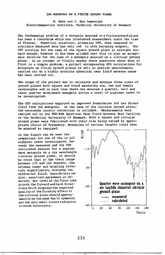
THE MONOPOLE ON A FINITE GROUND PLANE
H. Bach and J. Hau Lemanczyk Electromagnetics Institute, Technical University of Denmark
The fundamental problem of a monopole mounted on a finite ground plane has been a conundrum which has interested researchers since the time of Fresnel. Numerical solutions, primarily GTD, when compared to available measured data has only led to both becoming suspect. The GTD solution for the case of the square ground plane is straight forward enough, however it has been alluded that this is also an acceptable solution for the case of a monopole mounted on a circular ground plane. In an attempt to finally answer these questions about what at first is a simple problem, a project encompassing GTD calculations for monopoles on finite ground planes as well as precise measurements carried out on a highly accurate spherical near field antenna range has been carried out.
The scope of the project was to calculate and measure three sizes of ground planes both square and round measuring six, ten and twenty wavelengths and in each case there was mounted a quarter, half and three quarter wavelength monopole giving a total of eighteen cases to be investigated.
The GTD calculations employed an improved formulation for the direct field from the monopole. In the case of the circular ground plane--;the necessary caustic correction is included. Measurements were carried out on the TUD-ESA Spherical Near Field Antenna Test Facility at the Technical University of Denmark. Both a square and circular ground plane were fabricated with their size being varied by appropriate choice of frequency. Monopoles of various lenghts could then be mounted as required.
In the figure can be seen the comparison for one of the in all eighteen cases investigated, betwee~ the measured and the GTD calculated results for a quarter wave monopole on a six wavelength circular ground plane. It should be noted that in the theta range between 125 and 165 degrees, the antenna tower and mounting structure significantly disturbs the diffracted field. Outside this region, excellent agreement is observed. The level of the first lobe in both the forward and back directions which displays the expected quality of the focusing effect of the circular plane should approximately be the same due to symmetry and the very small direct radiation in these directions.
233
0 -,--------,'"'7-----------,
-10
-20
-30
0
Quarter wave monopole on six lambda diameter circular ground plane
30 60
measured calculated
90 120 150 180
Theta

MEASUREMENT AND CHARACTERIZATION OF THIN SLOT INTERIOR COUPLING*
A. J. L-udwigsen, H. G-. Hudson, . R-. J; King, K. S •. Kunz Lawrence Livermore National Laboratory
L-156 P.O. Box 808
Livermore, California 94550
Broadband (0.045-18 GHz), wide dynamic range (80-95 dB) measurements were made on a generic interior coupling test object at Lawrence Livermore National Laboratory's EMPEROR EM test facility using an HP8510A network analyzer. The coupling was through an aperture to an interior wire in a cavity. The current at the base of the wire was measured. For this coupling geometry the current response was attenuated below the aperture cutoff frequency, where a wavelength equals the aperture circumference, and, after peaking above the aperture cutoff, rolls off at higher frequency. The region below aperture cutoff offers a nominal 60 dB of attenuation for the apertures employed. Virtually no attenuation in the wire response occurred above cutoff.
We modified the aperture to see if more shielding could be obtained, both below and above cutoff. The aperture was partially blocked with a thin plate to form an annular thin slot. Little change in the response was noted until the slot height and depth were approximately equal and then only a modest amount of additional shielding was seen. The thin plate was farther enlarged so as to overlap the aperture. Shielding was now significantly enhanced (-20 dB) at frequencies below the original aperture cutoff frequency and for frequencies as much as three times higher than cutoff. Above that the reduction was more modest. The test geometry was then modified again to provide an interior offset wall so that the test object appeared to have a very thick hull. The test object in this configuration was positioned to form a continuous deep annular slot of shallow height at its base. Depth to height ratios were varied from 8: 1 to 200:1. Somewhat surprisingly there was little additional attenuation provided by the deep slot canpared to when the original thin hull was used except for the very high ratios and at very low frequencies where 20 dB attenuation was observed.
* Work performed under the auspices of the U.S. Department of Energy by the Lawrence Livermore National Laboratory under contract number W-7405-ENG-48.
234
AN OFFSET GRID SYSTEM FOR SAMPLING ACCURACY IMPROVEMENT
Y,P, LOH GENERAL ELECTRIC COMPANY, SPACE DIVISION
The current induced on a reflector is often sampled with a polar coordinate system, where the sampling points are taken as the intesections of a set of concentric c·ircles and a set of radial lines uniformly placed around the circles. The resolution is highest at the center of the grid, The density of the grid points decreases radially outward at a rate of two times the radial distance. If the peak current occurs at or near the grid center, this type of polar grid system is capable of providing satisfactory results. If the peak current location is significantly different from the grid center, then the sampling resolution may be inadequate and significant error may result. This situation is often encountered in reflector system design for beam scan applications.
A simple offset grid system is described in this work to enable the grid center be placed at the peak current location. If a point is picked from a region enclosed by a simply connected curve as the origin, the curve, in polar coordinates <r,e>, may be expressed as r=f(8), If a line is drawn from the origin to a point on the curve, the locus of the mid-point of the line segment has an expression: r=f(8)/2, If the line segment is divided into k divisions, then the locus of the i(thl point on the line is expressed as r=f<8>*<itk>, where i=l,,,k, It is obvious that the loci of the k points have exactly the same shape and orientation, regardless of the shape of the simply connected region.
The implementation of the offset grid system has also been described, The conversion from a conventional polar grid system to an offset grid system requires minimal efforts. Though the offset grid is developed primarily for reflector cuurent sampling, one may find its application for other types of problems where a continuous variable is to be represented by discrete numeical values. Examples are included,
235

AN APPROXIMATE METHOD FOR INCORPORATING THE WALL THICKNESS
INTO APERTURE CALCULATIONS
George A. Seely Electromagnetic Applications Division
Sandia National Laboratories Albuquerque, New Mexico 87185
A brief review of a method for incorporating the wall thickness into aperture calculations is given. This approximate scheme gives reliable results for ,\ ii!:: 6T, where T is the wall thickness. The effects of conductive wall losses and dielectric materials in the aperture on the resonance characteristics are considered. Numerical results are presented for a few cases of interest.
236
:1 I
GENERAL NUMERICAL PROCEDURE FOR CONCEPTION OF METALLIC AND DIELECTRIC LARGE BANDWIDTH HORNS
C. BROCHARD, J.M. MARTINAUD, J. TOURNEUR THOMSON-CSF, Division Equipements Avioniques
92242 MALAKOFF-CEDEX, FRANCE
The mixed finite-element method has already been used to compute the solution of the electric field integral equation (EFIE) involving arbitrarily shaped surfaces (A. BENDALI et aZ., El. Letters, vol 18, 641-642, 1982) where the reaction concept is applied to obtain a variational formulation of the EFIE containing the unknown electric equivalent currents and charges on the surface boundary.
The discretisation is based on the study of a family of mixed finite-elements introduced by P.A. RAVIART and J.M. THOMAS (Leet. Notes in Math., vol 606, 292-315) working on polynomial spaces which enable the elaboration of higher order approximations. The lowest order approximation leads to a set of basis functions proposed by RAO et aZ. (IEEE Trans., AP 30, 409-418, 1982) in an other approach.
Using the principles of the formulation, it is possible to take into account various homogeneous media and hence to modelise dielectric bodies such as lenses inside· or outside the horn. The method has been developped in an industrial context to calculate radiation patterns of electromagnetic horns. For example, with four very closely spaced ridges situated in the throat of the horn operating at 5 GHz, a computational time of 9 mins is needed on a DEC VAX 8600.
In order to reduce the number of unknows, higher order formulations are being studied like P1xP 1 or D2 triangular or rectangular finite-elements. These enhancements can simulate the radiation at a higher frequency without having to recreate the mesh of the model.
Comparisons between calculated radiation patterns and results of measurements always show a high degree of correlation which can be seen in the conference.
237
convergence of Numerical Techniques for Electromagnetic Scattering
J. s. Yu, Sandia National Laboratories/Albuquerque J, W. Williams, Booz, Allen & Hamilton Inc./Albuquerque
Method-of-Moment techniques are often employed to evaluate electromagnetic (EM) scattering from a body of revolution (BOR) that may be lossy and inhomogeneous. Convergence to a unique and correct solution for the EM scattering problem is the main concern of this paper. For a conducting scatterer BOR internal resonance problems are avoided by using a weighted combination of the continuity conditions on boundary surfaces. Discrete current densities on the boundary surfaces were found to be reasonably represented when ten (10) or more patches per wavelength along the BOR-generating curves were used. on each of the patches, there are N coefficients solved for the circumferential modes. These coefficients converge consistently when N exceeds the maximum value of the kp, where p denotes the radial dimension of the scatterer. Details of the EM model become increasingly important as the electrical size and complexity of the scatterer increase. Depending on the smoothness (or lack of it) and total length of the generating curve, there are occasions when more patches per wavelength are needed for satisfactory results. Examples using spheres, disks, cylinders, cones and loops were evaluated for generating curves up to dimensions of 40 wavelengths. Comparisons with exact solutions and measurements are used to validate numerical results. These examples provide practical guidance in modeling techniques for readers who are interested in the application of similar algorithms. They also provide some normalized scattering cross sections for targets that are not readily obtained by other techniques.
238

CLUSTERING, SURFACE PERTURBATION AND MATERIAL EFFECTS ON ABSORPTION AND SCATTERING BY RAYLEIGH PARTICLES
Herschel Weil Radiation Laboratory
Department of Electrical Engineering and Computer Science The University of Michigan Ann Arbor, Michigan 48109
For small particles shape-dependent internal resonances of the tnduced coupled electromagnetic-vibrational excitations lead to enhancements of the absorption and scattering cross sections crA and crs at certain critical frequencies, fc. The fc lie within the absorption bands of the bulk material of which the particles are composed and correspond to negative values of the real part €1 of the dielectric constant. The strength of crA(fc) and cr5(fc) depends on the amount of internal damping and so increases with €"(f C)'
We have tracked (computationally) the variation of the €c values corresponding to the major resonances for a number of particle configurations of closely spaced or agglomerated particles as the geometry is changed. Very rapid changes in the €c values for some of the resonances occur as the particles become very close or have just merged. We have also tracked similar effects for surface grooves and bosses on individual particles.
The tracking was done assuming the particles were composed of an unphysical low loss material in which €11 was assumed frequency independent. In this way resonances were only lightly damped and so showed up clearly while, at the same time, particle shape and spacing effects were separated from the effects of the €11 vs f val".iation in real materials ... For e·ach material, within· an absorption band, €11 (f) varies rapidly and. has a local maximum. Therefore plots for real materials of crA vs f can be considerably modified from those for the unphysical constant €11 case. One expects that fine structure will be blurred and possibly that major peaks will be damped out in which case there would· be little left of the resonance structure. By_computi~g crA vs fin absorption bands for a representative metal (Cu) and representative. dielectric {SiC) using published. €"(f) data we find that not all of the import.ant peaks· are heavily damped.
239
THE HRROR ESTIMATE OF EBCM
Guo,Yingjie Mao Yukuan
(N.orthwest T.elecommunica tion
Engineering Institute~cru.na)
In this paper a formular used to estimate the relative
error originated in the extended boundary condition meth
od(EBCM) is presented.
Assume that the scatt.erer is perfectly conducting.By ma
king use of the inner boundary condition we get. a Fredholm
integral equation of the first kind
(xfX,y,€1') ( 1 )
where x· represents the surface current.,y represents the
incident field and K is a non-singular integral operator.
Through some mathematical operation eq.(1) can be trans
~prmed into the following system of n linear algebraic
equations
( 2)
The approximate solution of eq.(1) can be obtained from
z and the relative error is given by
Delta=[( 1 +j'£,~..i FPKJ/ )+~Ti F//li( 1 +E) (3)
240
SALON 5/6 B-23-TRANSIENTS
Chairman: R.J. Porgorzelski THURSDAY-PM
Page 1:30 CHAIRMAN'S REMARKS 1:40 Propagating Pulsed Beam Solutions by Complex
Source Parameter Substitution E. Heyman and B.Z. Steinberg, Tel Aviv University; L.B. Felsen, Polytechnic Institute of New York ................ 242
2:00 Treatment of Two-Dimensional Slots in Thick Conducting Screens Using Sub-Cell FD-TD Models A. Taflove, F. Harfoush, Northwestern University; K. Umashankar and B. Beker, University of Illinois, Chicago; K. Yee, Lawrence Livermore National Laboratory .............. 243
2:20 Transient Electromagnetic Scattering and Complex Resonances of a Circular Strip J.T. Williams and D.G. Dudley, University of Arizona .......... 244
2:40 Transient Radiation From A Spherical Antenna-A Hybrid Approach J.D. Kotulski, Sandia National Laboratories .................. 245
3:00 COFFEE BREAK 3:20 Treatment of Wires & Multiconductor Bundles Using a Hybrid
FD-TD/MOM Approach K. Umashankar and B. Beker, University of Illinois; A. Taflove, Northwestern University; K. Yee, Lawrence Livermore National Laboratory ..................... 246
3:40 The Treatment of Edge Singularities In the Finite Element Solution of Maxwell's Equations in The Time Domain S.L. Ray, Lawrence Livermore National Laboratory ........... 247
4:00 Thin Seam Coupling: A Comparison of an FDTD Technique with an Eigenfunction Technique K.R. Demarest and S. Bakhtiari, University of Kansas Center for Research, Inc ..................................... 248
4:20 Transient Scattering by a Radial Line Joined to a Coaxial Waveguide D.G. Dudley, University of Arizona; Z. Shan-jie, Nanjing University, China ................................... 249
4:40 EMP-lnduced, Time-Domain Grazing Current For An Infinite Wire over the Ground K.C. Chen, Sandia National Labs ............................ 250
241

PROPAGATING PULSED BEAM SOLUTIONS BY COMPLEX SOURCE PARAMETER SUBSTITUTION
E. Heyman and Ben-Zion Steinberg Department of Electrical Engineering
Tel Aviv University Tel Aviv 69978, Israel
and
L.B. Felsen Department of Electrical Engineering/Computer Science
Weber Research Institute Polytechnic Institute of New York
Farmingdale, New York 11735
The complex source point method is extended to the time domain by con
sidering the field due to an impulsive source point with complex space coor
dinates and a complex initiation time. The resulting solution, which is a
particular analytic continuation of the free space time-dependent Green's
function, describes a propagating pulsed beam that has a moving peak along
the beam axis. Near the pulse maximum in the paraxial region, this new
field type is the Fourier transform into the time domain of the time-harmonic
paraxial Gaussian beam field but the solution also accommodates, in closed
form, observation points far from the beam axis and observation times long
before and after the peak has passed, By corresponding analytic continuation
of available space-time Green's functions for various propagation and diffrac
tion environments, one may generate directly the response due to the pulsed
beam incident on the environment.
242
TREATMENT OF TWO-DIMENSIONAL SLOTS IN THICK CONDUCTING SCREENS USING SUB-CELL FD-TD MODELS
Allen Taflove and Fady Harfoush EECS Department, Northwestern University
Evanston, IL 60201
Korada Umashankar and Benjamin Beker EECS Department. University of Illinois at Chicago
Chicago, IL 60680
Kane Yee Lawrence Livermore National Laboratory
Livermore, CA 94550
This paper reports simple, stable. highly accurate models of electromagnetic fields penetrating through narrow slots in thick conducting screens, The genera 1 mode 1 i ng approach is the finitedifference time-domain (FD-TD) method, which has been used previously to provide accurate models of large-aperture coupling into metal cavities. In this paper, the previous work is extended to deal with two-dimensional TE and TM cases where the slot gap is possibly much smaller than one unit cell of the FD-TD space lattice. Key physics that must be modeled properly includes, for the TE case, enhancement of the transverse electric field in the slot gap; for the TM case. exponential field decay due to below cutoff waveguide effects; and for both TE and TM cases, proper field penetration to the shadow side of the slot.
The narrow-slot FD-TD models incorporate field integration contours properly located within or near the slot. The contours permit implementation of the integral form of Maxwell's equations (Faraday's Law for the TE case, Ampere's Law for the TM case) to develop alternative finite-difference expressions at the slot which accQAJnt for the precise slot geometry and gap. In this manner, even slots of complex cross-section shape within thick screens can be modeled. The aim is to provide a straightforward treatment of coupling through apertures formed by 1 apped metal surfaces, screw joints, and simi 1 ar practica 1 joints between conducting surfaces.
Detailed results are shown for the magnitude and phase of E and H fields within, and penetrating behind, canonical two-dimensional slots in thick conducting screens. Results are derived using the new FD-TD narrow-slot models and highly-detailed method-of-moments (MOM) models. Excellent agreement is shown between FD-TD narrow-slot models employing a coarse space grid (O.l wavelength) and MOM models employing a very fine sampling resolution (less than· 0.01 wavelength).
243
Transient Electromagnetic Scattering and
Complex Resonanc8s of a
Circular Strip
Jef!erv T. Williama Donald G. Dudlev
Electromagnetics Laboratory Department of Electrical and Computet Engineering
University of Arizona Tucson~ AZ 85721, USA
We present the transient electromagnetic scattering from a thin circular strip mounted on a perfectly conducting sheet. Our source is an electric dipole located along the axis of the strip. The intent of this study is to develop a canonical scattering structure for use in emerging studies in parametric inversion. By applying system identification techniques to the simulated scattered field data, the complex resonances of the scattering object can be obtained. These resonances can, under certain conditions, be related to the geometry and material composition of the scatterer.
The complex resonances of the circular strip can be related to the poles of the scattered field by using a pole series expansion (singularity expansion method). We find these poles by solving the homogeneous integral equation of the induced surface currents on the strip. In addition, the complex resonances can also be related to the high frequency diffracted ray fields of the scatterer. We determine these resonances from a modified GTD solution for the scattered field of the circular strip. This GTD solution includes higher order slope diffraction, thus giving a more complete description of the complex resonances of the strip. A comparison of the resonances obtained by both of these techniques is made.
244

TRANSIENT RADIATION .FROM A SPHERICAL ANTENNAA HYBRID APPROACH
Joseph D. Kotulski Electromagnetic Applications Division
Sandia National Laboratories · Albuquerque ,NM 87185
The transient response of any object can be computed using a variety of methods in different time regimes.The early time region is normally approached by ray methods while the late time region is considered in the context of the modes of the structure. Recent developments in combining these two techniques take advantage of the rapid convergence properties in their respective regimes to synthesize the overall transient response. This hybrid technique is applied to the radiation of a spherical antenna which is excited by a ?-independent,6-gap voltage. The modal solution is separated (in the frequency domain) to give the ray-mode solution. The time response is obtained by taking the inverse Fourier transform of the hybrid ray-mode solution. This is compared to a FFT-generated solution of the original modal sum. The position of the observation point with respect to the excitation is varied and the use of this technique to antennas of different shapes is discussed.
245

TREATMENT OF WIRES AND MULTICONDUCTOR BUNDLES USING A HYBRID FD-TD/ MOM APPROACH
Korada Umashankar and Benjamin Beker EECS Department, University of Illinois at Chicago
Chicago, IL 60680
All en Tafl ave EECS Department, Northwestern University
Evanston, IL 60201
Kane Yee Lawrence Livermore National Laboratory
Livermore, CA 94550
The finite-difference time-domain (FD-TD) approach efficiently models complexelectromagnetic interactions involving arbitrary-shaped loaded cavities. Either time-harmonic or transient excitation can be modeled for calculating penetrating and scattered fields. If wires or multiconductor bundles are present, it is necessary to use a selfconsistent model which properly connects the physics of the wire or bundle with the physics of the enclosing cavity. Complications are introduced because the wire or bundle cross sec ti on can either be smaller than one space space cell or overlap several cells, possibly having an asymetrical location with respect to a cell (or cells).
This paper reports the development of a hybrid FD-TD/ MOM method based upon electromagnetic equivalences. First, it is shown that a wire bundle of electrically-small diameter can be replaced by a single wire with a properly defined cross section. Next, it is shown that the single equivalent wire can be accurately modeled -using FD-TD, even if the wire diameter is much less than one space cell, by building-in the 1/r singularities of the local scattered looping magnetic field and nadial electric field for appropriate FD-TD field components near the equivalent wire. Next, once the equivalent wire is modeled using FD-TD within the complex cavity of interest, the total tangential E and H fields on a virtual surface closely surrounding the equivalent wire are computed, and corresponding equivalent magnetic and electric currents on the virtual surface are compiled. Last, these equivalent currents are used as excitation for calculating induced currents on individual wires of the bundle. This computation is made off-line of the FD-TD program, using an auxiliary multiconductor analysis program or the regular integral equation method (MOM), depending upon the mutual coupling of the wires within the bundle. Arbitrary wire loads, interconnections, and branchings can be modeled in this manner.
Excellent validation results for induced currents on multiconductor bundles are reported here for time-harmonic exci ta ti on. Cases considered here include bundles comprised of unequa 1-1 ength wires (some of resonant length) in free-space and cavity environments.
246
THE TREATMENT OF EDGE SINGULARlTIES IN THE FINITE ELEMENT SOLUTION OF
MAXWELL'S EQUATIONS IN THE TIME DOMAIN
Scott L. Ray
Lawrence Livermore National Laboratory P.O. Box 5504, L-156, Livermore, CA 94550
The finite element method is a powerful technique for solving time domain electromagnetics problems. The technique provides accurate results and is applicable to a wide range of complicated geometries. Unlike finite difference techniques, where boundaries and internal structures must be described by "staircase" approximations, finite elements are able to conform to the actual geometry at the expense of increased computer time.
A number of general purpose electromagnetic codes utilizing the finite element method have been developed at the Lawrence Livermore National Laboratory. The basic approach is to first define a mesh which describes the problem at hand. Subsectional basis functions are then associated with the nodal points on the mesh. Electric and magnetic field components are expanded in terms of these basis functions with unknown, time-varying coefficients. The expansions are substituted into Maxwell's differential equations and a Galerkin procedure is used to reduce the resultant system of equations to a larger system of ordinary differential equations in the time variable. These ODE's are then integrated by any of a number of methods.
For computational reasons, relatively simple basis functions have been used in the past. For instance, bilinear functions are used in the two dimensional codes. If the underlying finite element mesh is not too coarse, these basis functions provide sufficient accuracy for most problems. In problems with sharp metallic edges though, errors are introduced as the bilinear basis functions cannot fully represent the field singularities, no matter how fine the mesh. As we are working with time domain solutions, errors are not limited to the vicinity of the edge. Errors, once introduced, prop11-gate throughout the entire problem space.
These errors can be reduced by introducing separate basis functions for nodes located on edges and corners. We have constructed a set of appropriate basis functions for 2-D problems based on the analytic solution for the metallic wedge. These basis functions contain the essential field singularities at .the corners allowing more accurate numerical solutions. In a typical problem, only a few nodes require this special, singular element treatment. Thus, the increase in computer time is small.
In this talk, the technique is illustrated by some 2-D waveguide iris studies. The irises have sharp metallic edges, requiring the use of singular elements. Results are compared to the case where bilinear basis functions are used everywhere.
247
Thin Seam Coupling: A Comparison of an FOTO Technique with an Eigenfunction Technique
Kenneth R. Demarest Sasan Bakhti ari
Remote Sensing Laboratory University of Kansas Center for Research, Inc.
Lawrence, Kansas 66045-2969
The Finite-Difference Time-Domain (FDTD) technique is a popular method of analyzing scatterers of small and moderate size by solving Maxwell's equations directly in the time domain. Using this technique, the scatterer is generally modeled as a collection of rectangular blocks (either perfectly conducting or dielectric), and the average electric and magnetic fields in each cell are calculated in a time marching fashion.
Several techniques have been developed to extend the FDTD approach so that geometries with thin apertures can be modeled. One such approach (K. Demarest, 1985, URS! Symposium, Vancouver, pp. 122) utilizes Babinet's principle to model an aperture in a conducting plane in terms of its dual - a magnetic wire. The use of this technique enables the modeling of apertures much thinner than the spatial grid used in the FDTD solution through the partial decoupling of the internal and external regions across the aperture.
In this paper, we compare results of this FDTD technique with those of a frequency domain, eigenfunction technique. The geqmetry used for this comparison is a hollow cylinder with a circumferential, 90°, aperture. The mode of excitation is a transient current source at the cylinder endcaps. The eigenfunction technique utilizes a Fourier-Bessel expansion in three regions, and the method of moments to enforce the boundary conditions between these regions. The frequency domain results are then transformed to the time domain.
Internal cavity responses calculated by both of these techniques will be compared as a benchmark test of the accuracy of the thin aperture, FDTD technique.
248
Transient Scattering by a Radial Line joined to a
Coaxial Waveguide
Donald G. Dudley
Electromagnetics Laboratory Department of Electrical and Computer Engineering
University of Arizona Tucson, AZ 85721, USA
Zhang Shan-jie
Department of Information Physics Nanjing University Nanjing, CHINA
We present the tranBient scattering caused by a branch radial line introduced into the outer wall of a coaxial waveguide. Our purpose is to obtain synthetic data for future use in parametric inverse experiments. In the parametric inverse problem, we shall use the transient reflected fields to estimate the width and depth of the branch radial line.
In the frequency domain, we formulate an integral equation for the tangential field in the aperture joining the coaxial and radial waveguides. We approximate the integral equation by a matrix (method of moments, MOM). We make appropriate use of asymptotics in the series expansions for the fields in both the coaxial and radial regi~. We use two expansions of the fields in the branch line and comment on appropriate values of parameters for the use of each. From the approximate solution obtained in the MOM, we produce the scattered reflected fields in the coax over a broad enough range of frequencies to make possible a numerical inverse transform to the time domain. We do the inverse transform with a combination trapazoidal and Filon method. Finally we give data for the scattered transient fields and comment on its use in parametric inverse experiments.
249
EMP-INDUCED, TIME-DOMAIN GRAZING CURRENT FOR AN INFINITE WIRE OVER THE GROUND
Kenneth C. Chen Sandia National Laboratories
Electromagnetic Analysis Division P.O. Box 5800
Albuquerque, New Mexico 87185
The EMP~induced, time-domain current waveform is obtained for an infinite wire over the ground under grazing incidence. In contrast to the published results, the maximum grazing current is found to be slightly larger when the ground conductivity is higher. The grazing angle for maximum current is also found to be smaller when the ground conduc;ivity is higher. For a typical ground conductivity of 10- S/m, the maximum current is approximately a factor of five larger than the typical value reported in the literature.
250
SALON 5/6 E-1-NOISE AND INTERFERENCE MODELING AND
SYSTEMS PERFORMANCE ANALYSIS Chairman: J.M. Morris
MONDAY-AM
Page 8:30 CHAIRMAN'S REMARKS 8:40 A Generalized Model for Noisy Signals in Locally
Optimum Detection I. Song and S.A. Kassam, University of Pennsylvania ......... 252
9:00 The Effect of Emission Noise From the Atmosphere on the Performance of Earth/Space Links at Ka and X Band E.K. Smith, JPL ............................................ 253
9:20 Second Order Non-Gaussian Noise Process with Applications to 0-Memory Non-Linear Devices D. Middleton, New York ..................................... 254
9:40 The Centroid of HF Interference and Its Application in Short Wave Communication Z. Guonai and Y. Shitai, China Research Institute of Radio Wave Propagation. . . . . . . . . . . . . . . . . . . . . . . . . . . . . . . . . . . . 255
10:00 COFFEE BREAK 10:20 The Performance of a Planar Array with Ideal Non-Linear Elements
R. Dwyer, Naval Underwater Systems Center. . . . . . . . . . . . . . . . . 256 10:40 Inverted Gram-Schmidt Processing for Interference Cancellation
K. Abend, lnterspec, Inc..................................... 257 11 :00' Detection of a Fluctuating Target in Both Noise and Clutter
J.G. Shin and M. Farhoomand, Stevens Institute of Technology. . . . . . . . . . . . . . . . . . . . . . . . . . . . . . . . . . . . . . 258
11 :20 Robust Suboptimal Detection K.S. Vastola and M. Kabatepe, RPI. ......................... 259
251
A GENERALIZED NODEL FOR NOISY SIGNALS IN LOCALLY OPTINUN DETECTION*
Iickho Song and Salee• A. Kassa• Department of Electrical Engineering
University of Pennsylvania Philadelphia, PA 19104
Detectors which are optimum for signal detection in the local case of weak signals have been of considerable interest, because detection of weak signals is more difficult than detection of signals which are comparable in strength to the noise process. Nost of the previous reported studies of locally optimum detection in non-Gaussian noise have dealt only with the case of additive noise.
In this paper we consider more general models of noisy signals, and obtain the structures of locally optimum detectors for several cases of interest. For example one rather general model of the noisy observations!; may be specified as
!; =a <9'> .!!.i +b(~) !; + p<9-,!; ,!!i )+ ~i, i =1,2, ••• ,n.
Here a(9,) and bCO-> are functions of the signal strength parameter•, the .!!!.i are a deterministic (mean) signal sequence, the !i form a zero-mean random-signal sequence, ~i is independent zero-mean additive noise, and the term pC9-,!;,!!i> allows the modeling of multiplicative or signal-de~endent noise, with N· a noise term generally correlated with ~j· The above formulation models the general case of vector signals, using which the treatment of array data or narrowband signals in addition to univariate observations is possible. One special case is obtained by taking pee-,!;,!!;> to be Cin the univariate case) cC,->S;N;, which models multiplicative noise. Another possibility is to make p<6-,!;,!!;>=c<9'>N;, to model signal-dependent noise.
For several such specific cases of the generalized model, explicit forms of the test statistics of locally optimum detectors will be given, under the assumption that the joint probability density functions of the noise and the signal are known.
*Research supported by AFOSR under Grant 82-0022.
252

THE EFFECT OF EMISSION NOISE FROM THE ATMOSPHERE ON THE PERFORMANCE OF BARTH/SPACE LINKS AT Ka AND X BAND
Ernest K. Smith Caltech Jet Propulsion Laboratory
Pasadena, CA 91109
Barth/space telecommunication systems typically employ minimum-noise front ends in their Barth terminal receivers. A consequence is that the increase in noise emission, during a modest increase atmospheric attenuation, will dominate the decrease in the signalto-noise ratio as compared to the effect of the signal attenuation. Thus with a system temperature of 15 K, a signal attenuation of 0.1 dB will raise the system temperature to 21 K for a 1.5 dB increase in noise, or a resultant S/N decrease of 1.6 dB; of which 94, is due to increase in the noise. On the other hand if the atmospheric attenuation were 20 dB, the noise level would increase to about 280 K, or about 13 dB; yielding a 33 dB decrease in S/N, of which only 39, is attributable to the increase in the noise component. Thus the relative importance of noise is a function of the magnitude of the atmospheric attenuation and of the system noise temperature in the absence of this attenuation. The magnitude of the attenuation selected will, in turn, depend on the choice of the percent of time that a desired service is to be available, the location, the operating frequency and time of year.
A~•32 GHz, a choice of 90 % service means that the limiting factor will be cloud attenuation. If 99, of the time (or higher) is chosen, then the limiting factor will be rain. Comparisons of X and Ka band transmission through the atmosphere at these two levels are given.
A conclusion is that cloud attenuation will become increasingly important, as usage of higher frequencies increases, as the cost of LNAs goes down, and as new services such as mobile satellite and direct broadcasting, with their lower reliability requirements become more popular. At the present time there is no statistical model for cloud attenuation.
253
SECOND ORDER NON-GAUSSIAN NOISE PROCESSES, WITH APPLICATIONS TO ZERO-MEMORY NONLINFAR
DEVICES•
David Middleton 127 East 91 Street New York,N.Y.
The canonical first-order Class A and B models of general nongaassian noise developed by the author since 1974 (D. Middleton, IEEE Trans. Electromag, Compat.,~-25,76-106,198~ and refs. there-in) are extended to second-order distributions. These new results explicitly contain all associated second-order correlations,as well as those of a general additive gaussian component. The first-order formulations are extended to include not only both broad- and narrow-band noise processes,but non-gaussian spaoe:-time fields themselves, which are sampled by general arrays and ape3:.,tures,
With these specific second-order nongaussian pdf's it is now possible to ,seneralize the "classical" seoond..order theory of output signal-to-noise ratios,speotra,and covariance functions following zero-memory nonlinear (ZMNL) devices (D. Middleton,Introduoi.ion 12. Statistical Cowmunication Theorz,McGraw-Hill,New York,196UJ,to in-elude explicitly the many important applications where the inter~rerence(which may or may not accompany a desired signal) is highly nonpusaian.
Because of the statistical-physical construction of these analytic,or "paps:metrio" nongaussian noise field and process models, the riles of the physical processes involved may be directly noted in the output results. The general results obtained here are illustrated by a number of examplessnongaussian noise through various nonlinear devices,angle modulation by canonical nongaussian noisetClass A cases), and the output covariances and spectra of full-wave square-law detectors,awong others.
* WorK supported unuer Coutraot ~UUU14-84-C-U417 with the Office of Naval Research.
254

THE CENTROID OF HF INTERFERENCE AND ITS APPLICATION IN SHORT WAVE COMMUNICATION
Zhou Guonai, Yan9 Shitai China Research Institute ct Radio Wave Pro?a9ation
ABSTRACT
the level ct HF interte,ence can be considered as the total effect caused by si9nals from a lot ct interference sources in various direct i ens. The I eve·I s ct HF interferences at various frequencies are different from each other. In order to characterize feature ct the interference, we consider the HF band as a whole and define a new ?arameter Interference Centroid Frequency (!CF).
n n I CF .. C Z: Fi *D (Fi ) J / C :Z:. D (Fi ) J (1)
i=l i=l
Where Fi is the i-th frequency, D(Fi) is interference si9nal ?Ower at Fi, and !CF is the first order moment ct D(F i).
The HF interference have been measured by an interference S?ectrum monitor. from Oct.11 to Oct.26,1964 in Xi An (E 106°54', N 34°16').
By the ex?eriment we have tel lowin9 conclusions:
" 1. The distribution ct !CF at the same time every day is normal
2. There is high correlation between !CF and toF2.
Based on the main characteristics ct !CF, we can use it to estimate the basic maximum usable frequency (MUFa) on a HF communication I ink and get real-time O?timal communication frequency on the HF I ink.
The method mentioned above tor the real-time selectin9 HF frequency has three advantages:
Real-time, lower cost and no interference to other usere.
255

The Performance of a Planar Array With Ideal Wonlinear Elements
Roger P. Dwyer
Waval Underwater Systems center Wew London Laboratory
Wew London, Connecticut 06320
There is considerable interest in predicting the performance of a planar array with nonlinear elements. For example, a planar array configuration is used in radar and comnunication systems. However, the interest is based on results formulated from the likelihood ratio. Although, under somewhat restrictive assumptions. Nevertheless, the likelihood ratio suggests performance improvements in certain environmental noise situations supported by experimental measurements.
The objective of the paper is to remove some of the assumptions needed under the likelihood ratio approach. However, the generality of the likelihood ratio is sacrificed in order to obtain specific performance predictions for a planar array of nonlinear elements. The information needed for the performance evaluation is based on the crosscorrelation estimate. In this regard the array configuration, receiver structure, and nonlinear elements are defined. With this information and the crosscorrelation estimate performance predictions are obtained for signals propagating in Gaussian and recurring impulsive noise environments. The performance predictions include the case when impulsive noise is propagating from the same direction as the signal. The results show that temporal and spatial filtering alone are not effective against impulsive noise. Whereas, the nonlinear elements are. Therefore, the total configuration with nonlinear elements generalizes array processing to include impulsive noise environments. ,
There are N sensors in each horizontal row and H sensors in each vertical column. Further processing utilizes a receiver which converts the data at the output of each nonlinear element into frequency components using a discrete-Fourier transform. The frequency components are then weighted and sU111111ed over all spatial sensors. The weights are chosen by maximizing a defined performance measure. However, this optimization procedure does not take into account the debilitating effects of impulsive noise. In order to treat theoretically the inclusion of a nonlinear element, to combate impulsive noise, the concept of an ideal nonlinear element is introduced. The ideal nonlinear element is introduced in the time-domain to facilitate deriving the theoretical performance of the resultant receiver in the frequency-domain. Therefore, the advantage of introducing an ideal nonlinear element is that this concept allows a theoretical performance prediction to be derived.
256

INVERTED GRAM-SCHMIDT PROCESSING FOR INTERFERENCE CANCELLATION
INTERSPEC, Inc. Conshohocken, PA,
Kenneth Abend and University of Pennsylvania
Philadelphia, PA
The Gram-Schmidt Orthogonalization (GSO) procedure is an efficient method for producing the conventional weight vector
~ = .!C' 1 for suppressing directional interference in an array of sensors. The inverted GSO procedure interchanges the roles of time samples and elements on the array to efficiently produce a weight vector which is the projection of the steering vector onto a linear subspace orthogonal to that spanned by the interference. Here, interference cancellation is achieved by approximating a "MUSIC" type orthogonal decomposition without the necessity for solving N eigenvalues and eigenvectors. By viewing the Hung-Turner-Kullstam algorithm as an inverted GSO procedure, new insights are achieved. Processing can be performed in place (at the element level) with only broadcast data required at the elements and only sums required at a central node. The number of computations at each element is small (though many elements must be used as auxiliaries) and only the number of time samples processed need depend on the number of interfering sources present. This number need not be known ahead of time because the algorithm lets you know when it is finished.
In the conventional application of GSO, the Nth port is the main beam port and the remaining N-1 portsmay be auxiliary elements or auxiliary beams. With the desired signal absent, the part of the received signal in the second port that is correlated with the signal in the first port is substracted from the second port so that ports one and two become uncorrelated. This procedure is continued from port to port until the main beam port produces a signal that is uncorrelated with all the other ports. Since directional interference is correlated from port to port, this nulls the interference. The equivalent of the inversion of an NxN matrix is achieved through the more accurate procedure of~£ u decomposition. Both the conventional and a simplified GSO algorithm will be discussed. The simplification is usefull when the adapted weights can be applied for signal detection after adaptation.
This GSO procedure requires a number of auxiliary ports determined by the number of interfering sources. By making the signal vectors orthogonal from time sample to time sample, instead of making the signals uncorrelated from port to port, the inverted GSO is adaptive to the number of interference sources.
257
DETECTION 0~ A FLUCTUATING TARGET IN BOTH NOISE AND CLUTTER
Jung G, Shin and M, Farhoomand Department of Electrical Engineering Stevens Institute of Technology Castle-Point-Station Hoboken, NJ 07030
The problem of detecting a fluctuating target in the presence of both clutter and noise is examined. The log-normal clutter which is the case of typical sea clutters and Rayleigh distributed noise are considered.
For both Swerling case 1 and Swerling case 2 targets which are either Rayleigh or log-normal distributed, a class of sub-optimum detectors are suggested. For each of the detectors, false alarm probabilities are evaluated, and the sensitivity of detection probabilities on target-to-noise and noise-to-clutter power ratios are discussed.
Performance comparison is made with other existing detectors through numerical results.
258
ROBUST SUBOPTIMAL DETECTION
Kenneth s. Vastola and Mete Kabatepe Department of ECSE
Rensselaer Polytechnic Institute Troy, New York 12180-3590
Typically, noise not only has non-Gaussian first order distributions, but also complex interdependencies. Further, it is often nonstationary. Since these factors lead to modeling inaccuracies, signal processing systems which are theoretically optimal may not perform as well in practice and may also be hard to implement.
A minimax theory of robustness has been developed which has lead to useful "most-robust" systems. However, we take the opposite point of view: Given a system (dictated by complex implementation or performance constraints), how robust is that system in arbitrary (non-Gaussian, dependent, nonstationary) noise. A recently developed general theory of qualitative robustness is applied to detection of signals in noise. Numerical results illustrating the practical usefulness of these results are presented. In particular the performance and robustness of several suboptimum detectors in Middleton noise is discussed.
259

260

SALON 5/6 F-1-EARTH-SPACE PROPAGATION AND
ATMOSPHERIC ATTENUATION Chairman: H.W. Arnold
TUESDAY-AM
Page 8:30 CHAIRMAN'S REMARKS 8:40 Slant Path Propagation Through Winter East
Coast Cyclones R.E. Marshall, North Carolina State University ................ 262
9:00 Duststorms and Microwave Propagation S. Haddad and U.A. Salman, University of Technology, Baghdad, Iraq .............................................. 263
9:20 Frequency Dependence of Slant-Path Rain Attenuation: Measurements and Analyses with Disdrometer Data T. Kozu, J. Awaka, Radio Research Lab, Tokyo, Japan, H. Fukuchi and K. Nakamura, Kashima Space Research Center, lbaraki, Japan ....................................... 264
9:40 A New Technique to Measure Complex Permittivity of Dust/Sand Samples of Storms at 1 D GHz and Their Particle Size Distribution S. Abdulla, H.M. Al-Rizzo, A. Mohammed, Space and Astronomy Research Center, Iraq. . . . . . . . . . . . . . . . . . 265
10:00 COFFEE BREAK 1 0:20 Comparative Study of Cumulative Rain Rate Distribution
Approximation Models M.S. Pontes, CETUC, Pontificia Universidade Catolica, Rio de Janeiro, Brazil........................... . . . . . . . . . . . . 266
10:40 Rain Attenuation Prediction Models Comparison for Tropical Climate Data M.S. Pontes, CETUC, Pontificia Universidade Catolica, Rio de Janeiro, Brazil....................................... 267
11 :OD Rain Rate and Rain Attenuation Measurements in a Tropical Region C.M. Einloft, L.A.R. De Silva Mello, CETUC, Pontificia Universidade Catolica, Rio de Janiero, Brazil.................. 268
11 :20 Angles of Arrival Fluctuation at 20 GHz on Earth-Space Path H. Fukuchi, T. Okuyama, K. Nakamura and K. Okamoto, Kashima Space Research Center, lbaraki, Japan .............. 269
261

SLANT PATH PROPAGATION THROUGH WINTER EAST COAST CYCLONES
ROBERT E. MARSHALL DEPARTMENT OF MARINE, EARTH AND ATMOSPHERIC SCIENCES
NORTH CAROLINA STATE UNIVERSITY RALEIGH, NORTH CAROLINA 27650
Severe weather is often associated with winter East Coast Cyclones. Some of these storms rapidly intensify off the Carolina coast and move northward through the heavily populated northeastern corridor. These storms produce bands of heavy liquid and frozen precipitation. These precipitation bands may cause significant attenuation and depolarization events on satellite links. The size, shape,· and motion ot convective cells within these precipitation bands will influence the behavior of space diversity systems.
The Genesis of Atlantic Lows Experiment (GALE) to be performed between January 15, 1986 and March 15, 1986 will employ a large network of meteorological RADARS to study the structure of precipitation bands associated with these storms. Data from the non-coherent National Weather Service RADARS at Volens, Virginia, Cape Hatteras, North Carolina, Wilmington, North Carolina, Athens, Georgia, and Tampa, Florida will be digitized in one (1) dBZ increments during GALE. This network will be supplemented by a system of coherent RADARS at Fort Fisher, North Carolina, Ocrocoke, North Carolina, Cape Hatteras, North Carolina, and Wallops Island, Virginia. Disdrometers and rain gauges will measure drop size distributions at Cape Hatteras and Fort Fisher.
, This paper will summarize the events associated with the GALE measurements. The current status of RADAR and in situ data set analysis and availability will be reported. A preliminary evaluation of single site and space diversity system performance during winter East Coast Cyclones will be given.
262

DUSTSTORMS AND MICROWAVE PROPAGATION
Safa Haddad and U.A.Salman Department of Electrical Engineering,
University of Technology, Baghdad, Iraq.
ABSTRACT- Dust samples, collected from storms at30,70 and 100m heights, are analysed by Scanning Electron Microscope to find the probability density sizedistribution by number and to explore the possibility of finding a correlation between particles shapes and sizes. Effects of duststorms on microwave propagation is also investigated.
Samples were placed in five size groups and measured data are presented in tabular form in detail and probability density size distribution is plotted. Calculated values of the proposed shape correction factor, cs, are in fair agreement with the existing results at lower heights but deviates slightly as height increases. Further, average values of ce indicate the possibility of non-spherical particles at higher heights in larger number. The average dimension rates, determined statistically from the five size groups of the three samples, do not exihibit any strong evidence of correlation between particles shapes and sizes.
The introduction of cs reduces attenuation, and phase shift, of microwaves propagating in non-uniform storms. From the illustrations of differential horizontal and vertical attenuations and phase shifts for four particles sizes and different frequencies at 5% moisture and 100m visibility, it is observed that attenuation and phase shifts of microwaves are more in the horizontal than in the vertical plane. Finally, cross polarizations of the waves are also calculated assuming ellipsoidal particles of storms with varying moisture contents and frequencies and the results are discussed.
263
FREQUENCY DEPENDENCE OF SLANT-PATH RAIN ATTENUATION: MEASUREMENTS AND ANALYSES WITH DISDROMETER DATA
T. Kozu *, J. Awaka *, H. Fukuchi **, and K. Nakamura**
* Radio Research Laboratory (RRL), Tokyo 184, Japan ** Kashima Space Research Center, RRL, Ibaraki 314, Japan
The slant-path propagation experiments using Japanese geostationary satellites CS and BSE have been performed at the Kashima Space Research Center of RRL (Fukuchi et al. , IEEE Trans. AP-31, 4, 603-613, 1983). The elevation angles of the CS and the BSE paths at Kashima are 48° and 37°, respectively. In addition to down-link beacon (CS;l9.5GHz, BSE;ll.7GHz) attenuations, up-link communication channel (CS;28.9GHz, BSE; 14.4GHz) attenuations were measured for more than ten rainfall events during 3 years from 1979 to 1981. We report the properties of attenuation ratios (AR's) obtained from the up- and down-link · attenuation measurements and the analyses using raindrop size distributions (DSD's) measured by a disdrometer.
AR's (dB/dB) varied from event to event ranging from 1.8 to 2.4 for the CS link (28.9/19.SGHz, circular polarization) and from 1"~3 to 1.9 for the BSE link (14.4/11. 7GHz, vertical polarization) • Attenuation dependence of AR was also observed for some events. AR's were statistically determined by comparing the cumulative distributions of attenuations. The determined values, which increase slightly with the increase of attenuation level, are 2.0-2.1 for the CS link and 1.5-1.7 for the BSE link.
For examining the relation between each of the properties of AR mentioned above and DSD, AR' s were calculated by using the disdrometer data for rainfall events corresponding to the attenuation measurements. For the BSE" link, agreements between measured and DSD-derived AR's are very good, while for the CS link, DSD-derived AR's are somewhat larger than the measured ones except for a few events. One possible reason of the discrepancy in the CS link is the effect of the melting layer attenuation. Because, radar observations along the paths found that, for the CS link, most of the measurements were made for relatively light rain with the melting layer, and. that, for the BSE link, most of them were made for heavy convective storm.
Although "further examination must be made concerning the discrepancy ·in the CS link,· the good agreements in the BSE link suggest that the DSD's on the ground correlate with those along the slant-path and are useful for predicting the frequency dependence of slant-path attenuation.
264

A HEif TECHNIQUE 'l'O MEASURB COMPLBXPBRMrr'l'IVITY OP DUST/SAHD SAMPLES OF
STORMS AT 10 GBI ARI) THIER PARTICLE SIZE DIS'l'llmUTIOH
Abdulla.S.A Rea. Al-Riazo.B.M Rea.Aas Mohammed.A.A Eng.Aas.
ABS'l'RAC'f 1
Space And Aatronaay Research Center Scientific Research Council
Sand and/or dust storms are very frequent in the Arab world includi119·Iraq,due to which performance of .the microwave C0111111unication ayatema,particularly the microwave linka,are severely affected.Thia iamediatily warrants the investigation of thepropagation behaviour of microwave -duri119 storms.To this end in view,a new technique has been propoaed to measure first the COllplex permittivitiea of the dust/sand samples collected frOII the storms aa well aa the simulated samples at lOGBl.'l'he suggested technique ia baaed on the principle analysis given by [conatantine ,A.B.,et al,IEBE Tran. Geoacience Blee. 16, 316-323) but with a newel approch.In this method,reflec.tion and tranS11ission losaea caused by the samples are measured separately by utilizing a circulator in a balanced bridge configration.The permittivities of the samples are also measured by conventional techniques.The two results are found to have good agreement •
. ,Particle size distributions of the sedimentation technique in order to investigate the dust storm effects on microwave propagation.The work ia under further inviatigation.
265
COMPARATIVE STUDY OF CUMULATIVE RAIN RATE DISTRIBUTION APPROXIMATION MODELS
MARLENE S, PONTES CETUC - Pontificia Universidade Catolica Rua Marques de Sao Vicente 225 22453 - Rio de Janeiro - BRAZIL
Log-normal and gamma approximationsare extensively used to model rain rate cumulative probability distri butions. Recently an alternative model has been pro posed by Moupfouma (Ann. Telecommunic., 37, n9 3-4,1982: pp. 123-128), based on experimental data obtained in an equatorial region.
A comparative evaluation of these three approxi mations has been performed both for the climates pro posed by the CCIR (Radiometeorological data, Rep. 563-2: Prop. in non-ionized media, vol. V) and for rain rate data obtained over a three year period in a tropical climate (Rio de Janeiro, Brazil). The cumulative distri butions were obtained by least-square fitting the lo garithims of the probability for the available rain rate figures. This procedure provides a better accuracy for low time percentages, associated to higher rainfall rates, which are the most important for rain attenuation prediction. The results show that the log-normal and the Moupfouma approximations are more effective to represent the rain rate cumulative probability distri butions.
266

RAIN ATTENUATION PREDICTION MODELS COMPARISON FOR TROPICAL CLIMATE DATA
MARLENE S. PONTES CETUC - Pontificia Universidade Catolica Rua Marques de Sao Vicente 225 22453 - Rio de Janeiro - RJ
A large number of rain attenuation prediction models are found in the literature. However, almost all the rain rate and rain attenuation data used to testify these models were obtained in temperate climates.This paper presents a comparative evaluation of several models to predict attenuation, given the point rain statistics, based on measurements taken place in tropical cli mates.
The comparison included the models proposed by Lin (BSTJ, 56, 1977, pp. 1581-1604), Crane (IEEE Trans. Comm. 28, n9 9, 1980, pp. 1717-1733)°, CCIR (Rep. 338,. Vol. V), Boithias-Battesti (J. Tiffon, Ann. Telec., 38, n9 5-6, 1983, pp. 245-261), Misme-Fimbel (Ann. Telec., 30, 5-6, 1975, pp. 149-158) and Assis-Einloft (Ann.Telec., 32, n9 11-12, 1977, pp. 478-480). The experimental data have been obtained in five 11 GHz microwave links in different regions of Brazil where continuous measurements of rain attenuation were made during one to five years periods. In two of these regions the rain rate was simultaneously recorded and for the remaining three links the CCIR rain cumulative distributions were used.
The results show that for most of the cases the Misme-Fimbel and the Assis-Einloft methods have a good agreement with exper.!_ mental data.
267

RAIN RATE AND RAIN ATTENUATION MEASUREMENTS IN A TROPICAL REGION
,CLAUDIO M, EINLOFT LUIZ A,R, DA SILVA MELLO
CETUC - Pontificia Universidade Catolica Rua Marques de Sao Vicente, 225 22453 - Rio de Janeiro - BTazil
A great amount of data on rain rate and rain attenuation sta tistics obtained in temperate climates have been published iii recent years. However for tropical regions, subJect to higher rain rates, only a few results are available. This paper reports five years of simultaneuous measurements of rain rate and rain attenuation on a 8.6 Km, 11 GHz collllllercial link in the urban area of Rio ae Janeiro, Brazil. The work is part of an extenside study that intends to cover the climatic regions of Brazil.
The major results of the investigation are: (1) The rain atte nuation probability distribution for the link, obtained from continous chart records during the periods from 15th July 1977 to 15th July 1981 and from 15th July 1982 to 15th July 1983; (2)" The point rain rate probability distribution taken near to one end of the link during the same period; (3) The theoretically predic ted attenuation distribution obtained using the measured rain rate distribution.
The measured attenuation distributions show figures as high as 20 dB rain attenuation· exceeded for 0.01% of the worst y~ar. The rain rates have been obtained with 5 min. integration time and than· adjusted to 1 min. integration time using the model of Damosso et al (CSELT Rapport Tecnici, VIII, n9 4, 1981, pp.299-302). The corresponding corrected rain rate distributions are used to predict the rain attenuation distributions. For this calculation the Assis-Einloft method (Ann. Teleconununic., 32, n9 11-12, 1977, pp. 478-480), which is an approximattion of the Misllle-Fimbel method (Ann. Teleconununic., 30, n9 5-6, 1975, pp. 149-158), is used. The theoretical results are in satisfactory agreement with the measured data in almost all cases.
268
ANGLES-OF-ARRIVAL FLUCTUATION AT 20 GHZ ON EARTH-SPACE PATH
H. Fukuchi, T. Okuyama, K. Nakamura and K. Okamoto
Kashima Space Research Center, Radio Research Laboratory, 893-1, Hirai, Kashima-machi, Ibaraki, 314 Japan
Because the angles-of-arrival(AOA) fluctuations along an earth-space path affect the quality of space communications systems using high frequency bands with high directivity antennas, a reliable estimation of the AOA fluctuation is considered to be of importance to design a new space communications systems.
The beacon signals of Japan's geos.tationary communications satellites, CS and CS-2, have been received by a 13 m parabolic antenna with the elevation angles of about 48° at Kashima Space Research Center, Radio Research Laboratory. These signals are circularly polarized waves at 19.45 GHz. The AOAs of the signals were measured by the following two methods simultaneously. One is an interferometer and the other is a tracking error measurement system which has been used in auto-tracking facilities of the antenna. By comparing the fluctuations of AOA measured by above two methods with each other, it was confirmed that the tracking error signals can be used for AOA measurements with sufficient accuracy by applying proper corrections for the antenna movement.
The AOAs of the beacon signals were continuously measured at the rate of one sample per second and were used to derive the standard deviations of AOA over 3 minute interval. The fluctuation of AOA increased in the daytime and was larger in summer than in winter. The main cause of these general character is tics is the f 1 uctua tion of refractive index of the atmosphere along the path. In summer, anomalous fluctuations of AOA with the standard deviation larger than 5 milli-degrees were observed. For example, in August, 1982, the standard deviation of s.s milli-degrees and the peak fluctuation of ± 25 millidegrees from the average direction were observed in the daytime. In some of these large AOA fluctuation events, thick clouds were observed near the propagation path. These anomalous fluctuations of AOA seem to be caused by multi-path propagation effects or diffraction due to thick clouds. near or along the path.
It is found that cumulative distributions of AOA standard deviations in both elevation(EL) and traverse(azimuth X COS EL) directions are nearly the same. This suggests that the fluctuation of AOA is isotropic on such a propagation path with a large elevation angle.
269

270
SALON 5/6 F-2-THEORY OF SCATTERING ANO OF
GROUND-WAVE PROPAGATION Chairman: A. lshimaru
TUESDAY-PM Page
1:30 CHAIRMAN'S REMARKS 1:40 Transient Response of Dipole Antennas on Two-Layer Media
S.Y. Poh, J.A. Kong and M.J. Tsuk, MIT ..................... 272 2:00 Second Moments of Waves After Propagating Through a
Discrete Random Medium L. Wang and C.C. Yang, The Penn State University .....•...... 273
2:20 Effects of Non-Spherical Statistics and Multiple Scattering on EM Wave Propagation in Discrete Random Madia V.K. Varadan, V.V. Varadan and Y. Ma, The Penn State University ....................................... 274
2:40 Interpretation of Backscatter Cross Sections for Normal Incidence Using Unified and Two-Scale Full Wave Analyses of Rough Surfaces E. Bahar and M.A. Fitzwater, University of Nebraska-Lincoln; D.E. Barrick, Ocean Surface Research, Boulder, Colorado ........................................... 275
3:00 COFFEE BREAK 3:20 Passive Remote Sensing of Terrain with a Dense Distribution
of Particles L. Tsang, University of Washington .......................... 276
3:40 Communications in A Three Rough Layered Conducting Media S. Bishay, Ain·Shams University, Cairo, Egypt. ............... 277
4:00 General Reciprocity and Symmetry Relationships for the Polarized Radiative Field in Plane-Parallel Media A.M. Khounsary, H.T. Eom and W.M. Boerner, University of Illinois ........................................ 278
4:20 Definition and Interpretation of S-Matrix for Distributed Meteorological Targets Measured by Coherent Polarimetric Radars M. Chandra, A. Schroth and E. Luneburg, DFVLR, lnstitut Fur HF·Technik, West Germany ....................... 279
271
TRANSIENT RESPONSE OF DIPOLE ANTENNAS ON TWO-LAYER MEDIA
S. Y. Poh, J. A. Kong and M. J. Tsuk
Department of Electrical Engineering and Computer Science and Research Laboratory of Electronics Massachusetts Institute of Technology
Cambridge, Massachusetts 02139
The study of transient electromagnetic waves of dipole antennas in layered media leads to applications in geophysical probing, subsurface communications, and microelectronic integrated circuits with high-speed switchings. Early- and late-time responses of half-space and two-layer media for a transient pulse have been investigated in the literature. A complete timedomain response can also be obtained with the Cagniard-de Hoop method when the reflection coefficients at the boundaries are independent of frequency, a condition satisfied only for nondispersive media.
In this paper we study the complete time response with the double deformation technique, which involves contour integrations on the complex frequency and wavenumber domains. The relevant pole singularities, branch points and branch cuts will be discussed in detail to facilitate physical interpretations of the results. In particular, we identify the significance of a set of poles contributing to the early response and essential for the preservation of causality. Through such an approach, the wave behavior of modes and rays associated with the various singularities on the complex planes can be analysed. We study both vertical electric and magnetic dipole antennas as well, as two-dimensional sources on a two-layer medium, where the medium can· be dissipative and dispersive. The difference between the transient responses of the electric and magnetic dipoles as a result of the difference in the singularities associated with the Fresnel reflection coefficients will be examined and illustrated.
272

SECOND MOMENTS OF WAVES AFTER PROPAGATING THROUGH A DISCRETE RANDOM MEDIUM
Likarn Wang and C.C. Yang Department of Electrical Engineering
The Pennsylvania State University University Park, PA 16802
Abstract
Although the effects on a propagated wave from random scattering in a particle-distributed medium have been widely studied, research works were essentially limited in the computation of the first moment of the propagated or scattered wave. This is attributed to the mathematical complexity of the conventional approach when higher moments are evaluated. Recently, a new method for particle scattering has been proposed by one of the authors. In this new method, a correlation function for such a discrete random medium is derived. Having this correlation function, we can use the theory of continuous scattering to discuss the effects of particle scattering including multiple scattering effect. A mutual coherence function is computed in this paper. In doing so, the correlation between the permittivity fluctuation at one point and the wave field at the other point has to be evaluated first. This correlation can be computed using the Novikov-Furutsu theorem when the permittivity fluctuation possesses a Gaussian distribution; however, this is not true in a discrete random medium. Therefore, a new theorem needs to be established. Methods and results for this correlation and the mutual coherence function are presented.
273
EFFECTS OF NON-SPHERICAL STATISTICS AND MULTIPLESCATI'ERING ON EM WA VE PROPAGATION
IN DISCRETE RANDOM MEDIA
V.K.Varadan,V.V.Varadan,Y.Ma Department of Engineering Science and Mechanics
The Pennsylvania State University University Park, PA 16802
At millimeter wavelengths it is necessary to model in detail the geometry, orientation and statistics of the inclusion or discrete phase in a random medium. Previous calculations for the coherent and incoherent fields using the T-matrix to model the inclusion response used spherical statistics even for non-spherical scatterers. This is unrealistic for large volume fractions c > 0.15. Values of the pair distribution function for aligned and randomly oriented spheroids obtained with Monte Carlo simulation are used in the multiple scattering calculations. The new results are compared with old results using spherical statistics.
274

INTERPRETATION OF BACKSCATTER CROSS SECTIONS FOR NORMAL INCIDENCE USING UNIFIED AND TWO-SCALE
FULL WAVE ANALYSES OF ROUGH SURFACES
E. Bahar, Electrical Engineering Department University of Nebraska-Lincoln NE 68588-0511
D.E. Barrick, Ocean SUrface Research, Boulder CO 80303 M.A. Fitzwater, Electrical Engineering Department
University of Nebraska-Lincoln NE 68588-0511
A specific and important application of rough-surface scattering at normal incidence concerns short-pulse satellite microwave altimeter return from the sea surface. In addition to its use to :measure. ocean waveheight at nadir as on Seasat, the altimeter has also been employed to infer wind speed from the backscattered signal intensity, since the roughness statistics depend strongly on surface wind. Up to now, attempts to establish a quantitative connection between altimeter nadir backscattered cross section (per projected area) and wind speed have employed a physical-optics derived specular-point :model that (i) relates the backscatter cross section to rms surface slopes, and subsequently (ii) relates surface slopes to wind speed in some manner. Unfortunately, the returns predicted thereby are several dB greater than the measured, leading to use of empirical rather than theory-based models to establish the connection. This discrepancy can only be due to the inadequacy of the simple, specular-point model, as it has been used, to describe the backscattered return even from a gently sloping sea at normal incidence.
The full wave solution for rough-surface scattering reduces to an integral similar in form to the physical optics or perturbation solutions (E. Bahar,Radio Science, 16, No. 3, 331-341, 1981). In its derivation from the exact telegraphists' equations, multiple scatt~ring is neglected. The full wave solution has been shown to reduce to the specular-point result in the high frequency limit, and to the perturbational result (with the correct polarization dependence) in the low frequency limit. Since it is valid across the spectrum for all roughness scales, it is not necessary to adopt the two-scale model to analyze rough surface scattering problems (E. Bahar and M. A. Fitzwater, IEEE Trans. Antennas and Prop. AP-32, No. 7, 730-734, 1984). In recent work however, (E. Bahar.and D. E. Barrick, Radio Science, 18, No. 2, 129-137, 1983), the full wave solution has been artificially decomposed into two components to elucidate the mechanisms at play in the two-scale models discussed above.
275
PASSIVE REMOTE SENSING OF TERRAIN WITH A DENSE DISTRIBUTION OF PARTICLES
Leung Tsang Department of Electrical Engineering
University of Washington Seattle, Washington 98195
Passive remote sensing has been applied to terrain media where particles are densely distributed. The radiative transfer equation, in its classical form, has been commonly used to study the volume scattering effects of these problems. However, it has been demonstrated, both experimentally and theoretically, that independent scattering is not true in media with a dense distribution of particles, and the classical radiative transfer equation is not valid.
Recently, a set of "new" transfer equations has been derived from analytic wave theory for dense media. The differences between the "new" set of transfer equations and the classical ones will be discussed. The new equations still preserve the advantages that (1) multiple scattering of the incoherent intensities are included, (11) energy conservation is satisfied, and (111) numerical solutions are tractable. Numerical ·results of the brightness temperatures based on the theory will be illustrated using the physical parameters of the terrain media.
276
COMMUNICATION IN A THREE ROUGH LAYERED
CONDUCTING MEDIA
SAMIRA T. BISHAY
Department of Mathematics, Faculty of Science Ain-Shams University, Abbassia, Cairer Egypt.
The problem of communication in the sea bas been considered by many authors. Some of them regarded the sea as a tw<r iayered media (atr-sea water), the bottom of the sea bas not been included. However, the effect of the sea bottom cannot be neglected in some cases. Thus, other authors ascertained theoretically the importance of the sea bottom on radio .wave propagation, ill certain situations, and coDBklered the sea as a three layered inedis(air-sea water-,r.otllJJ). Recently, the effect of the variations which occur in the UPPer surm.ce of the sea, due to '.sea -waves, was investigated. The part of sea under investigation was 'taken to be of finite depth and the surface of the sea bottom was assumed to be invariable. In this work, the problem of communication: in the sea has been considered in terms of a three layered media. The variations which may occur in the sbape of both the lower and upper surfaces, due to sea waves, are also taken into consideration. The effect of these variations is studied using the perturbation method. The results obtained are compared with those mentioned elsewhere.
277
GENERAL Rl!lCIPmlCI'l'Y .AND SYMMETRY BELATI<HlHIPS Fem 'DIE POLARIZED RADIATIVE FIELD IN PLANE-PARALLEL MEDIA
Ali M. Kh01.lllsary, Hyo J. Eom, and Wolfgang-M. Boemer COIIIIIUllications Laboratory, SEL-4210
Department of Electrical Enginnering & Computer Science (DI/C 154) University of Illinois at Chicago
Chicago, IL 60680-4348
A Green's matrix formulation of the problem of polarized radiative transfer in inhomogeneous plane-parallel media with anisotropic scattering is developed. This procedure leads to the introduction of a fundamental source matrix which is the response of a medium to an imbedded \lllidirectional, \lllitary polarized probe. Depending on whether the source and the observation points are located in the interior or on the boundaries of a medium, four sets of scattering matrices in terms of the diffuse vector fields are defined. The fourth set, which corresponds to the case in which both the source and observation points are on the boundaries, is analogous to Chandrasekhar's scattering matrices (for the standard problem).
The reciprocity and synmetry properties of the single scattering process, in conj\lllction with a method of parametric differentiation are then used to·obtain a series of reciprocity and synmetry relationships governing the above scattering matrices. These relationships greatly facilitate the theoretical developlll!nt, and reduce the computational expenses of evaluating the polarized radiative fields in inhomogeneous anisotropic scattering media.
In view of the linearity of radiative transfer, the Green's matrix approach in conj\lllction with the superpositon principle allows the evaluation of both the emergent and the internal polarized radiative fields in inhomogeneous plane-parallel media with arbitrary internal and/or external source(s). The scattering matrices can be evaluated through an adding-doubling scheme, although the method of parametric differentiation offers a more direct, but slower alternative.
Evaluation of the total (transmitted, reflected, & internal) polarized field of an inhomogeneous scattering medium is fundamental for many passive and active remote sensing problems at various wavelengths within the meter-to sub-millimeter spectral regions. These include, for example, vegetative canopies with discontinuous underlayer(s). Specfic problems are isolated and solution approaches are discussed.
278
DEFINITION .AND INI'ERPRETATION OF $-MATRIX FOR DISTRIBUfED METEOROLOGICAL
TARGETS MEASURED BY OOHERENr POLARIMETRIC RADARS.
M. Chandra A. Schroth E. Lilneburg
DFVLR, Institut filr HF-Teclmik, 8031 Wessling, West Gennany
' The polarimetric theory available in open literature to-date emphasis primarily the polarimetric interpretation and evaluation of radar measured s-matrix of fixed i.e. coherent targets.
The application of such techniques, howeyer, in distributed meteorological targets (say due to measurements by polarimetric weather radar), such as rain tee. , remains , as yet, unclear. The main cause of this 'gap' , we believe, lies in the lack of investigations of the following key aspects:
(i) The basis and the definition of the backscatter s-matrix of randomly distributed targets such as meteorological precipitations (in stationary randan equilibrium) •
(ii) The vital link between the elements ·of the measured s-matrix and the mi~hysical propertie~ of the ensemble of scatterers constituting the distributed target. These micorphysical properties refer to the size, shape and orientation spectn.un and the scattering amplitudes of the constituent particles in the seatter volume.
Our paper will address these two outstanding aspects. We would thus outline the interpretation of the individual s-matrix elements, for a distributed target, in tenns of the micrqphysical properties of the scatterers. In doing so we would use the conceptual resource already available in the fonnalism of the coherency matrix and the 4 x 4 r.ill.ler's matrix.
,I
Furthennore using well-known drop-size distribution and the scattering amplitude calculation of raindrops (from the T-matrix method) we would theoretically obtain the s-matrix of rain precipitation to illustrate our technique. The polarimetric interpretation (i.e. the description of the Huynen-fork) would then follow. Indeed the dependence ot the s-matrix (for rain target) on the drop-size distribution, thennodynamic phase and orientation of the scatterers (depending on the time available to the authors) would also be investigated and described.
279

280

SALON 10 F-3-MOBILE RADIO, REFRACTION, ANO MULTIPATH
Chairman: W.J. Vogel WEDNESDAY-PM
Page 1 :30 CHAIRMAN'S REMARKS 1 :40 Review ol US Papers on Measurement ol Relractivity Profiles
R.J. Taylor, Johns Hopkins University, Applied Physics Lab .... 282 2:00 A Model for UHF Coherent and Incoherent Field Intensities
in Suburban Mobile Radio R.L. Campbell, Michigan Technological University; W.J. Helms, University of Washington ........................ 283
2:20 Meteorological Studies ol Radar Ducting Phenomena S.M. Babin and J.R. Rowland, Johns Hopkins University, Applied Physics Lab. . . . . . . . . . . . . . . . . . . . . . . . . . . . . . . . . . . . . . . . 284
2:40 Low-Angle Multipath Errors T. Griesser and C.A. Balanis, Arizona State University.. . . . . . . . 285
3:00 COFFEE BREAK 3:20 Tree Attenuation Statistics at 869 MHz Derived from
Helicopter-Mobile Vehicle Measurements J. Goldhirsh and J.R. Rowland, The Johns Hopkins University, Applied Physics Lab; W.J. Vogel and G.W. Torrence, University of Texas ....................... 286
3:40 A Model lor Multipath Propagation H.N. Kheirallah, Qatar University, Doha, Qatar; H.M. Rashwan and A.K. Aboul-Saoud, Alexandria University, Alexandria, Egypt.. .............................. 287
4:00 Alignment and Transmission Measurements of Quasi-Optical Millimeter Wava Systems C.E. Mayer, University of Texas .............................. 288
4:20 Prediction ol Wide-bandwidth Time-Domain Radio Transmission Loss Over Irregular Terrain R.J. Luebbers and W.A. Foose, The Penn State University. . . . . . . . . . . . . . . . . . . . . . . . . . . . . . . . . . . . . . . . . . . . 289
4:40 Propagation Modeling lor Land Mobile Satellite Communications W.T. Smith and W.L. Stutzman, Virginia Polytechnic Institute ........................................ 290
281

REVIEW OF U.S. PAPERS ON MEASUREMENT OF REFRACTIVITY PROFILES
Robert Joseph Taylor Johns Hopkins University Applied Physics Laboratory
Ninety papers and reports on measurement of refractivity profiles in the atmosphere were identified and reviewed. These papers and reports were principally from U.S. researchers working during the last 20 years. These papers and reports covered the following subtopics: radiosondes; refractometers; radars; microwave radiometry; acoustic sounders; comparisons of radars, lidars, acoustic sounders; sounding systems; satellite measurements; evaporation ducts; structure function parameters; and refractivity data bases.
A significant number of papers describe problems associated with the present operational method (radiosondes) that is used to measure refractivity profiles. Many believe the present use of radiosondes to measure refractivity profiles is highly questionable for use in RF propagation prediction. Such measurements may be sufficient when the refractivity gradients do not exceed the measurement capability of radiosondes. But one cannot assess beforehand when radiosondes are sufficient without first measuring the actual gradients with better instrumentation. Thus this circular problem logically requires that better instrumentation be used all the time and that radiosonde measurements not be use for RF propagation prediction.
Microwave refractometers have sufficient frequency response and resolution to measure a significant fraction of the potential refractivity gradients which exist in the atmosphere. The best method for their use probably is to include them as sensors on airplanes and to measure the refractivity profile along the flight path of the aircraft.
Radars hold promise for measurement of the refractivity gradient. This potential technique could provide a continuous monitoring of the refraction profile over. properly instrumented ships and land stations. Although microwave radiometry does not provide the required resolution of the temperature and humidity profiles, it might be effectively used to determine horizontal gradients of the refr~ctivity in various directions from the prime profile determined by radar or refractometers. Satellites could give·a broad overview of the horizontal extent of refractivity conditions. Thus various measurement methods when used together can complement each other and give a compatible and comprehensive description of the spatial and temporal evolution of the refractivity conditions.
282
A MODEL FOR UHF COHERENT AND INCOHERENT FIELD INTENSITIES IN SUBURBAN MOBILE RADIO
Richard L. Campbell Department of Electrical Engineering
Michigan Technological University Houghton, Michigan 49931
Ward J. Helms Department of Electrical Engineering
University of Washington Seattle, Washington 98195
If a suburban area is illuminated by a CW source, the field at each point in the region may be obtained by summing the direct wave, a ground reflected wave, and a diffuse component due to reflections from objects in the suburban area. The average coherent intensity is obtained from the vector sum of the direct and specular ground reflected waves, with possible attenuation due to scattering. The coherent intensity model is compared with ~easurements of the coherent component of horizontally polarized signals in residential Seattle using the assumptions that attenuation due to scattering is low and the direct and ground reflected components are equal.
The diffuse field intensity has been modeled in the past by assuming N horizontally travelling waves arriving at the receiver from all directions. If single scattering is assumed, with scatterers illuminated by the coherent wave, then the nearby, elevated scatterers will be most important. The intensity of the diffuse component will then be a function of the angular distribution of scatterers around the receiver. The model for the diffuse component, using the distribution of buildings along residential streets, is compared with measurements of the distribution of signal arrival angles in residential Seattle.
283

METEOROLOGICAL STUDIES OF RADAR DUCTING PHENOMENA
Steven M. Babin and John R. Rowland Applied Physics Laboratory
The Johns Hopkins University Johns Hopkins Road
Laurel, Maryland 20707
This paper presents the results of radar ducting studies using a 3 GHz (S-band) radar and a 5 GHz (C-band) radar at Wallops Island, Virginia, during May and August of 1985. Helicopter acquired meteorological measurements were made over the ocean while the helicopter was tracked with the aid of C and Sband transponders mounted on the aircraft. Temperature, relative humidity, and atmospheric pressure were measured by sensors located in a ventillated probe mounted beneath the helicopter. Altitude was measured with a radar altimeter. The helicopter made soundings by flying a sawtooth trajectory from an altitude of 3 m to a maximum of 1.5 km. Modified refractivity versus altitude was plotted to locate regions where radar ducting could occur. The helicopter measurements were correlated with the Sband radar backscatter returns from clear air phenomena and sea surface returns caused by ducting. The meteorological measurements were also correlated with quantitative amplitude data received from the C- and S-band transponders. A large number of soundings showed evidence o.f radar ducting. Helicopter acquired meteorological measurements are shown to be very useful in understanding low level radar ducting phenomena.
284

LOW-ANGLE MULTIPATH ERRORS
Tiaothy Griesser and Constantine A. Balanis Departaent of Electrical and Coaputer Engineering
Arizona State University Teape, AZ 85287
Radar systeas experience significant difficulties when tracking low altitude targets over the ocean because of multipath effects. Reflection off the ocean surface provides an alternate path of travel for the radar echo, as if a target image existed below the water surface. If the radar beaawidth is not sufficiently narrow, the radar will not be able to resolve the target fro• its iaage, and it will track a false·target whose position can fluctuate widely above and below the actual target position. The radar systea, under such conditions, will frequently lose track of the target.
The tracking error due to the aultipath phenomenon was analyzed using mathematical models for a monopulse radar system. Computational algorithms have been constructed for both smooth and rough reflection models of the earth interface to illustrate the loss in tracking accuracy whenever the radar system is unable to. separate the returned echoes fro• the target and its image. Targets at ranges of up to 12,000 feet and at altitudes of 5 to 35 feet above sea water have been investigated. Antenna 3-dB beaawidths of 0.9 and 0.25 at 9 GHz and 35 GHz. respectively, were considered. The calculations included provisions for antenna polarizations and side lobes,. as well as divergence factors to account for the curvature of the earth surface.
Coaputer demonstrations using the smooth surface model, which are valid when the Rayleigh criterion is satisfied, predict undesirable tracking behavior in which the radar boresight frequently comes to equilibrium in a direction far away from the actual target position. This aodel, being strictly deterministic, can specify uniquely the tracking error as a function of the positions of the target and the radar relative to the earth's surface. Equilibrium points located using the smooth surface analysis were found to be either stable or unstable. The stable points reveal directions toward which the antenna will rotate, while the unstable points represent· directions away from which the antenna would turn if it was slightly displaced from equilibrium. The location of stable and unstable points becomes particularly important in deteraining if the antenna will track the target with its main beaa or with one of its sidelobes.
Simulations using the rough surface model are -inherently indeterminate and must be analyzed using stochastic models of the ocean surface. With this model, the rough surface theory introduces a band of possible equilibrium directions within which the antenna boresight is expected to lie.
285
TREE ATTENUATION STATISTICS AT 869 MHz DERIVED FROM HELICOPTER-MOBILE VEHICLE MEASUREMENTS
Julius Goldhirsh and John R. Rowland Applied Physics Laboratory
The Johns Hopkins University Johns Hopkins Road, Laurel, Maryland 20707
Wolfhard J, Vogel and Geoffrey W. Torrence Electrical Engineering Research Laboratory
The University of Texas at Austin, Austin, Texas 07558
With the advent of planned communications systems between moving vehicles and geostationary satellites, i.e., Mobile Satellite Systems, a paucity of information still exists as to the degradation effects of trees intersecting earth-satellite paths. A week long experiment was conducted in October of 1985 in the Maryland area to address this question.
Helical antennas transmitting a CW beacon level at 870 MHz at right hand circular polarization were mounted on a Bell Jet helicopter. In one mode of operation, the helicopter flew at constant height at fixed elevation angles and near parallel to a moving van containing receiving and data acquisition equipment. The van traveled along highways as well as along country type roads, where in all cases the roads were, in general, lined with trees of the deciduous variety which contained approximately 80% of its foliage. A body of attenuation statistics have been developed which characterizes the effects of elevation angle to the satellite, side of the road driving, and road type. It is apparent that the occurrence of tree attenuation for the stated geometry is influenced markedly by right side or left side of the road driving as well as elevation angle to the satellite. For example, where the elevation angles were approximately 30° and the vehicle was located on the right side of the road nearest the trees through which the propagation path passed through, peak tree attenuation levels were measured (averaged over one second) ranging from 10 to 20 dB. In another mode of operation, the attenuation effects of various tree types were examined for the case in which the van was stationary and located behind the particular tree being examined. The helicopter flew by on one side of the. tree at fixed heights, white· the van was positioned on the other side. By comparing the measured signal levels for the case in which the propagation path.passed through a particular tree with those measured with the van in front of the tree, the attenuation effects as a function of elevation angle were derived. As an example of such a measurement, a bare deciduous sassafras tree showed a peak attenuation of 10 dB (1 second average) for the case in which the van was l-0cated 4.3 m away and the signal path was at an elevation angle of 30°, with the tree height being approximately 10 m.
286

A MODEL FOR MULTIPATH PROPAGATION
H.N.Kheirallah, Dept. of Elec. Eng., Qatar Univ., Doha, Qatar,
H.M.Rashwan and A.K.Aboul-Saoud, Dept. of Elec. Eng., Alexandria
Univ., Alexandria, Egypt.
This paper presents a modified version of Ruthroff's multipath
model(BSTJ,50,2375-2398,Sept. 1971)in which most of its earlier li
mitations have been overcome. Although flat earth is still being
assumed, the simple mathematical expressions permit a quick inves
tigation of the.propagation phenomena under several anomalous con
ditions. Between two limits of layer heights, the model predicts
the presence of two refracted rays in addition to the direct one.
Both refracted rays have negative differential path delays with
respect to the direct tay. The incorporation of an antenna beam an-
gle disc.rimination results in the ,u
amplitude of the upper ray being
·Smaller than that of the lower ray
in most of the cases. The amplitu
des of both refracted rays esceed
that of the direct ray as the layer
height approaches its maximum limit.
The model permits the analysis of
both.frequency and space diversity
improvements. A typical numerical
example is shown in fi~ure indicating
that the closer the layer to the an
tennas the larger is the dependence
of the fading on the antennas sepa
ration. Sensitivity analysis of the
fading to variations in the propaga
tion medium can also be performed.
287
_,
-·· t"tldit lewel (~) ""· rnup,,....:)' lCI~>. PaLh 1•",lth:4UK11,vr11-
dMnt below lhlll l11)'er::-lt0 N ...-11t11/Ka,.,,riodionl 10Uun Ltw
lity•r=-.SOO N wuta/1Ca,J11yer t.igl1t llbove 1-r witlltYlll:.20..,
tr•-•l ~Id rire•,"• Wit..-.. ti1llf,lllt111l1Q11 h:U,),10,1),11 .... ,...
ALIGNMENT AND TRANSMISSION MEASUREMENTS OF QUASI-OPTICAL MILLIMETER WAVE SYSTEMS
Charles E. Mayer Electrical Engineering Research Laboratory
The University of Texas at Austin
Quasi-optical or open structure receivers have become the best performers in the millimeter wave regime due to the non lossy nature of open air propagation. Separate components are used to collimate, guide, diplex, filter, and converge the millimeter waves on their typical journey from the receiving antenna to the feed horn. Each of these components is allowed five degrees of freedom of movement. Thus the rapid growth of the alignment search space demands a systematic approach.
An alignment sequence and technique are presented here to allow full realization of a receiver's design expectations. Paramount to this technique are two constant power noise sources, namely, blackbody radiators at ambient and liquid nitrogen temperatures. A concentric geometry of the two radiators allow receiver coupling to be calculated versus soli~ angle of the beam. A different concentric geometry allows the intensity distribution (probably Gaussian) of the collimated beam to be measured. Using this technique, a beam profile can be mapped from the feed horn through the entire quasi-optics system, thereby dictating alignment corrections. Further, power conservation calculations allow subsystem transmission measurements to be obtained. The surface finish requirement of reflectors necessary to prevent scattering losses can easily be experimentally quantified.
A set of measurements is presented showing the alignment and transmission of a 240 GHz quasi-optical receiver. Included in thes, optics is an error compensating secondary mirror in use with the University of Texas 5-m millimeter wave telescope.
288
PREDICTION OF WIDE-BANDWIDTH TIME-DOMAIN RADIO TRANSMISSION LOSS OVER IRREGULAR TERRAIN
Raymond J. Luebbers and WI I I iam A. Foose Communications and Space Sciences Laboratory
Electrical Engineering Department · The Pennsylvania State University University Park, Pennsylvania 16802
Methods for propagation development 100 MHz to
predicting the effects of terrain on the of narrow band radio waves have been under for many years. In the frequency range of 10 GHz reflection and diffraction are the
dominant mechanisms of interaction between radio waves and terrain, and several different propagation prediction models are available for computing narrow-band path loss over irregular terrain.
Due to the use of spread spectrum techniques in tactical communication systems, Interest in the effects of terrain on wideband signals has Increased. However, most current narrow-band propagation models are not applicable to wideband signals CP. F. Sass, IEEE Trans. Veh. Tech., No. 2, May 1983). One exception is a propagation model based on the Geometrical Theory of Diffraction which approximates the terrain prof I le as piecewise-I I near and utll lzes wedge diffraction to compute reflection and diffraction effects. Results obtained with the GTD model have been compared with narrowband measurements for a variety of frequencies and terrain types, and the good agreement obtained has been reported Ce.g. R. J. Luebbers, IEEE Trans. Ant. Prop., Vol. AP-32, No. 9, Sep 1984). ., Using the narrowband GTD model as a starting point, a wideband terrain-sensitive model Is being developed which Is capable of predicting the band-limited impulse response of a radio channel Including terrain effects. The path loss computations are performed In the frequency domain using the GTD, with the Fast Fourier Transform then used to produce the corresponding time domain results. Predictions obtained using this model are compared with wideband Cup to 250 MHz clock rate) t1me-domaln measurements obtal~ed by the Stanford Research Institute, and Illustrate the validity and u·sefulness of the GTD in prediction of terrain effects on wideband radio propagation.
289

PROPAGATION MODELING FOR LAND MOBILE SATELLITE COMMUNICATIONS
W.T. Smith W.L. Stutzman
Virginia Polytechnic Institute and State University Electrical Engineering Department
Satellite Communications Group Blacksburg, VA 24061
The signal margin for planned land mobil:e satellite communication systems will be relatively small. Therefore, attenuation due to propagation effects can have a significant impact. Primary among these is vegetative shadowing and secondarily, multipath fading.
In this paper we present results of a study on the modeling of vegetative shadowing and multipath fading. A combined statistical distribution function is derived to evaluate the fraction of time that signal levels are expected to occur. This, in turn, is related to the environment of the mobile and the satellite link parameters. The model is useful in estimating the fraction of time that attenuation levels are encountered for a variety of vegetations,· highways, and locati.ons.
290
WYNDHAM C F-4-RADAR METEOROLOGY AND OCEANOGRAPHY
Chairman: J. Goldhirsh THURSDAY-AM
Page 8:30 CHAIRMAN'S REMARKS 8:40 HF Radar Measurement of Surface Circulation in Delaware Bay
B.J. Lipa and D.E. Barrick, Ocean Surface Research, Woodside, CA. . . . . . . . . . . . . . . . . . . . . . . . . . . . . . . . . . . . . . . . . . . . . . 292
9:00 A Simple Radar Backscatter Model for Near Grazino Sea H.J. Eom, J. Okeke and W.M. Boerner, The University of Illinois ................................................... 293
9:20 The Mapping of Dynamic Topography in the Southern Oceans Using Altimeter Data E.B. Dobson, The Johns Hopkins University Applied Physics Lab. . . . . . . . . . . . . . . . . . . . . . . . . . . . . . . . . . . . . . . . . . . . . . . . 294
9:40 Studies of the Linearity of the Relationship Between Long Ocean Waves and Their Microwave Reflectivity Modulation D.E. Weissman, Hofstra University; W.C. Keller and W.J. Plant, U.S. Naval Research Laboratory .................. 295
10:00 COFFEE BREAK 10:20 Use of Synthetic-Aperture Radars for Measurement
of Precipitation R.K. Moore, University of Kansas Center for Research; D. Atlas, University of Maryland ............................. 296
10:40 Consideration of Platform Motion in CODAR (HF Radar) Remote Sensing of Ocean Surface Conditions D.E. Barrick and B.J. Lipa, Ocean Surface Research ........... 297
11 :00 Dual Frequency, Dual Polarization Backscatter Measurements of Rain K.A. Clark, J.D. Kelly, M.E. Lavelle and J.D. Nespor, Boeing Aerospace Co.. . . . . . . . . . . . . . . . . . . . . . . . . . . . . . . . . . . . . . . 298
11 :20 C-Band Dual Linear Polarization Radars and Rain Induced Attenuation K. Aydin, T.A. Seliga and Y. Zhao, The Pennsylvania State University. . . . . . . . . . . . . . . . . . . . . . . . . . . . . . . 299
11 :40 Radar Remote Sensing of Hail: Comparison of Dual Polarization and Dual Wavelength Techniques T.A. Seliga and K. Aydin, The Pennsylvania State University; V. Balaji, Nat'I Center for Atmospheric Research, Boulder, Co.. . . . . . . . . . . . . . . . . . . . . . . . . . . . . . . . . . . . . . . . . . . . . . . . 300
291
Hf RADAR MEASUREMENT OF SURFACE CIRCULATION IN DELAWARE BAY
6. J. Lipa and D. E. 6arrlck Ocun Surface Research, Woodside, CA 94062
We describe resulls of • sludy or surface circulation In Oe.laware Bay, fall 1984. This study is based on two-dimensional currenl veloclly maps measured· by an Hf radar remole sensing system (Codar) ,very 1.5 hours over a period of a month. The flow In lhls bay is slrongly domlnaled by semi-diurnal tides and outflow from the north but variu due lo winds and waves generaled by storms. The rapidly changing depth along with lhe enclosing, irregular coastline adds to the complexily of circulation. Tidal coefrlclents are computed over the map and results correlated with location and bottom topography. Tidal components are lhen sublraclad rrom the current velocities and the residuals correlated with wind velocities and surface runoff. The use of these results lo understand clrculalion in such complex, enclosed areas is discusHd.
292

A SD1PLB lWWl IIIICISCM"Mll 1DEL !'OR NBA1l GBAZDG SEA.
Hyo J. l!'.Clll, Jonas Okeke and WOlfgang-M. Boemer Ccmiamications Laboratory, SEir-4210
Department of Electrical Engineering & Caaputer Science (111/C 154) university of Illinois at Chicago
Chicago, IL 60680-4348
ABS'flUICr
A sinl>le backscattering model is proposed for the interpretation of like-polarized radar backscatter behavior near grazing sea from the L band to the sub-am wavelength regimes. It is assumed that sea waves under high sea wind have both breaking-wave components and water sprays associated with white caps. 'l'he proposed radar backscatter formulation models the breaking wave as a perfectly conducting· wedge and the water sprays as a randall layer embedded with small dielectric spheres. '1'he total radar backscatter is then the sum of wedge-diffracting fields and incoherent return from a Mie or :Rayleigh randall layer. 'l'he proposed model is tested against existing experimental data collected for various sea conditions, frequency, polarization, and grazing angle. It is found that a certain type of radar backscattering behavior near grazing angle can be satisfactorily explained with the proposed si~le approach.
293
THE MAPPING OF DYNAMIC TOPOGRAPHY IN_ THE SOUTHERN OCEANS USING ALTIMETER DATA
Ella B. Dobson The Johns Hopkins University Applied Physics Laboratory
Johns Hopkins Road Laurel, Maryland 20707
The altimeter is presently the only satel_lite-borne instrument which shows _promise in measuring dynamic topography globally over the worlds oceans. Many research efforts have demonstrated that mapping and time histories of currents and eddies can be extracted from the altimeter signal. Most of these results, with a few exceptions, have reported work in the North Atlantic. This paper presents the results of expanding these type studies to an area of the world's oceans where very little data has been available in the past. Maps of a region off the coast of South Africa indicate a strong correlation between the altimeter height signature (height variability) and the general position of the Agulhas current region. A discussion of altimeter mapping of this current system and its associated eddies is discussed along with an evaluation of the relationship between current flow strength and the ability of the altimeter to make the measurement. That is, given our knowledge of current velocity in this region, what is the required height signal to noise necessary to detect the current or eddy. In addition, some attention is given to the various methods of extracting dynamic topography signals in regions such as the Southern Oceans where no good geoid is available.
294
STUDIES OF THE LIHEARITY OF THE RELATIONSHIP BE'l'WEEli LONG OCEAN WAVES ARD THEIR MICROWAVE REFLECTIVITY MODULATION
D.E. Weismiaan Hofstra University Hempstead, IIY 11550
w.c. Keller and W.J. Plant U.S. Naval Research Laboratory Washington, D.C. 20375
MaaJ ot the applications ot radar remote seaaiag to the measurement ot ocean wave spectra employ the assU111ption that a linear tranatormation relates this •input• to the retleotivity variations at the •output•. Experimental microwave radar and environ.mental data have been analyzed to study this relationship, The measurements ot the coherence tuaotion, the radar backscatter speotrWII and loag wave spectrum indicate the simple one-variable traaater tuaotion model is not Juatitied. However the departure troa this simple model can be explained in terms ot additional wind speed and environmental toroes, that are consistent with linear system behavior. l uaitied two-dimeaaional model tor the radar backscatter as a tuaotion ot the wave slope and wind speed provides consistent interpretations tor the behavior ot the average radar cross section and the modulation transfer tuaotion. For the purposes ot airborne and spaoeborne remote sensing, a generalized definition of the modulation traaater function is deti~ed and its linearity properties are analyzed with I-band radar data. Also the statistical properties ot the •input• and •output• signals have been analyzed to evaluate the linearity ot this relatioaahip.
295
USE OF SYNTHETIC-APERTURE RADARS FOR IEASUREMENT OF PRECIPITATION
R.K. Moore Radar Systems and Remote Sensing Laboratory
The University of Kansas Center for Research, Inc. Lawrence, Kansas 66045
and D. Atlas
Department of Meteorology University of Maryland
College Park, MO 20742
The use of radars measuring backscatter from rain drops to estimate precipitation rates is well established. To observe relatively small precipitation·cells at long ranges requires antennas that are so large that they are difficult to carry on aircraft or spacecraft, so use of synthetic-aperture methods is suggested.
Because of the random motions of raindrops in the turbulent atmosphere, the received signal has a Doppler-shifted spectral width set by the drop velocity distribution. This target motion can therefore result in degraded performance of a syntheticaperture radar (SAR).
Here it is shown that significant azimuth-resolution improvements can be achieved for spaceborne SARs for all reasonable drop velocities, although the pixel width achieved is far greater than that for stationary targets. For airborne SARs, only the lowest drop velocities result in improved resolutions over those of non-coherent radars. The power required for a SAR is, as for stationary targets, independent of the azimuth resolution •
. ;/ Calculations are given to shown how a test of this concept for spaceborne radars may be conducted using the SIR-CC-band radar planned for flight near the end of the decade. To achieve adequate resolution in the vertical plane, the SIR-C would have to be operated with the long antenna direction in the vertical plane, resulting in sizeable ambiguities in azimuth. Careful selection of target storms that are sufficiently isolated should allow the test to proceed, although an operational space meteorological SAR would require a wider antenna. The test could also be performed with the radar looking near vertical without the ambiguity problem. The sensitivity of the system is such that rain at rates below 0.2 mm/hr. would be detectable.
296

Consideration of PJatform Motion in CODAR (HF Radar) Remote Sensing of Ocean Surface Conditions
DonaJd E. Barrick Belinda J. Lipa Ocean Surface Research
J J 31 <zanbroo.k Court 165 Haraoss Road BouJder, CO 80303 Woodside, CA 94062
Compact HF radar systems c:alled CODARs are presently in operation from offshore oil rigs for reaJ-time mapping of ocean surface currents and monitoring of the waveheight directional spectrum. Based on backscatter from the surface waves, the system derives its information from the DoppJer spectrum of the echo signal. In certain cases, these systems must operate from semi-submersibJes, which fJoat at anchor and move in response to the Jonger period ocean waves. The rig-induced horizontal motions of the antenna will produce DoppJer shifts in the same generaJ · region of · the signaJ spectrum where the current and wave information lie. Hence, their effect on information e1traclion is assessed, and methods developed that compensate for and remove motion contaminations.
Simulations show that very Jong-period motions (greater than 50 s) do not appreciably contaminate e1traclion of currents from the f'ttst-order pea.le in the spectrum; rather, they produce gaps in the anguJar coverage of the resulting current maps. The shorter, wave-following motions with periods "'IO s produce lower-amplitude phase modulation sidebands lying outside and below the first-order pea.le region. However, these motion-induced pea.ks fall precisely on top of the second-order Doppler sidebands that are inverted to give the waveheight directional spectrum. Use of the e1pressions for second-order scatter from the sea shows that the motion sidebands, if ignored, can produce biases up to "-251 in energy, tending to overpred.id sea waveheight by ---121. We therefore develop and demonstrate methods for measuring the horizontal platform motions with an accelerometer, simultaneously with the sea echo, and removing their Doppler contamination from the averaged, secondorder aoss spectra before inverting. EumpJes of these effeas based on measured data are shown.
297
DUAL FREQUENCY, DUAL POLARIZATION BACKSCATTER MEASUREMENTS OF RAIN
K.A. Clarlt 1 J.D. Kelly~ M.E. Lavelle, J.D. Nespor Boeing Aerospace Company M/S 8H-51 P.O. Box 3999, Seattle,.WA 98124-2499
There has been a great deal of interest in the response of radar. systems to rain. Radar backscatter from rain is of particular interest to radar analysts because of the impact it has on detection and tracking of targets, and to the radar meteorologist as a means for measuring relevant storm parameters. Most of the radar backscatter efforts to date have only concerned the amplitude coefficients of the backscatter matrix for frequencies of X-band and below. Recently, much interest has developed concerning backscatter in the MMW region and in obtaining the relative backscatter matrix of rain. The present study addresses the measurement of the complete relative backscatter matrix for rain based upon measurements employing dual frequency, dual polarized coherent radars of X-band . (8.9 GHz) and Q-band (45 GHz). In this regard, the experiment was conducted so that the backscatter matrix could be determined on a pulse-to-pulse (X-band) and sweep-to-sweep (Q-band) basis. The results from the measurements are presented in a variety of ways. These include the statistics of the backscatter matrix coefficients versus rain rate, co-polarization null distributions and Mueller matrix parameters for three rain rates. Decorrelation times based upon the complex auto-correlation function, as well as, the auto-covariance are compared. Typical Doppler spectra and cross-spectra of the backscatter returns are presented, and conclusions from this study are presented.
298
C-BAND DUAL LINEAR POLARIZATION RADARS AND RAIN INDUCED ATTENUATION
K. Aydin, T. A. Seliga and Y. Zhao Communications and Space Sciences Laboratory
Department of Electrical Engineering The Pennsylvania State University
University Park, PA 16802
Radiowaves at C-band (4-6 GHz) can experience significant attenuation in rain. Therefore, data obtained from C-band meteorological radars that perform dual linear polarization measurements should be corrected for the rain induced attenuation effects. The true reflectivity factor at a certain gate can be recovered by determining the two way attenuation up to that ·gate. On the other hand, the true differential reflectivity at the same gate can be obtained by compensating for the two way differential attenuation between the Hand V polarizations up to that gate. This paper presents a procedure enabling dual polarization C-band data to be corrected for attenuation and differential attenuation caused by rain. This is accomplished by making use of only C-band. data itself. Simulations of radar measurements from·disdrometer data are used to demonstrate the procedure which may be applied at other attenuating wavelengths as well.
299
RADAR REMJTE SENSING OF HAIL: COHPARISC!l OF DUAL POLARIZATION AND DUAL WAVELENGTH TECHNIQUES
T. A. Seliga and K. Aydin Communications and Space Science Laboratory
Department of Electrical Engineering The Pennsylvania State University
University Park, PA 16802
v. Balaji Convective Storms Division
National Center for Atmospheric Research Boulder, CO 80307
Differential reflectivity (Zoa> radar measurements have been used in detecting hail with the results to date being very encouraging. Recently, the authors have defined a new hail signal (Hoa> based on the signature of rain on the (ZH,Zoa> plane. This signature is obtained from disdrometer measurements of raindrop size distributions. It is observed that data for rainfall are clustered in a certain region of the (ZH,Zoa> plane. Hence, certain (ZH,Zoa> pairs lying outside this rainfall region are considered to be due to ice phase hydrometeors. This paper focuses on the comparison of the Hoa hail signal with the dual wavelength hail signal as described by Tuttle and Rinehart (J. Clim. and Appl. Meteor., 1914-1921, 1983). Hailstorms observed on June 4, 1983 and June 13, 1984 by the CP-2 radar system of NCAR during MAYPOLE'83 and '84 in Colorado are used for this purpose. Ground based confirmations of hail for these storms were obtained by mobile chase teams.
300

WYNDHAM C F-5-SENSING THE EARTH'S SURFACE
Chairman: V. Kaupp THURSDAY-PM
Page 1 :30 CHAIRMAN'S REMARKS 1 :40 Near Real Time Terrain Clutter Cross Section Measurements,
Analysis and Graphical Display K.V.N. Rao, J.F. Lennon and W.G. Stevens, Rome Air Development Center, Hanscom AFB .......................... 302
2:00 Lava Flow Texture From SIR-B R.W. King, V. Kaupp, W. Waite and H.C. MacDonald, University of Arkansas; L. Gaddis and P. Mouginis·Mark, University of Hawaii at Manoa,. Honolulu, Hawaii ............. 303
2:20 Radar Backscatter Measurements on Soma Vegetation Samples LE. Allan and Y.M.M. Antar, National Research Council of Canada, Ottawa .................................. 304
2:40 Microwave Backscamar Coefficients of Artificially Grown First Year Sea Ice D. Xue, R.K. Moore, and T.H. Lee Williams, The University of Kansas Center for Research; R. Onstatt, Radar Science Lab, ERIM, Ann Arbor, Michigan ............... 305
3:00 COFFEE BREAK 3:20 Scattering From A Dielectric Disk With and Without Inhomogeneity
L·K. Wu and K. Demarest, University of Kansas Center for Research. . . . . . . . . . . . . . . . . . . . . . . . . . . . . . . . . . . . . . . . . 306
3:40 Fine Resolution 1 O GHz Radar Signatures of Four Components of an Urban Scana: Lawn Grass, Concrete Walkway, Asphalt Pavement & Curb R. Zoughi, R.K. Moore and J. Bredow, The University of Kansas Center for Research. . . . . . . . . . . . . . . . . . . . . . . . . . . . . . . . . . . . . . . . . 307
4:00 Geology of Central Iran M. Razani, ITRC, Tehran, Iran ............................... 308
4:20 Effects of Vegetation Cover on the Microwave Radiometric Sensitivity to Soil Moisture M. Razani, ITRC, Tehran, Iran ............................... 309
301

NEAR REAL TIME TERRAIN CLUTTER CROSS SECTION MEASUREMENTS, ANALYSIS AND GRAPHICAL DISPLAY
K.V.N. Rao John F. Lennon
William G. Stevens Electromagnetic Sci enc es Di vi si.on
Rome Air Development Center· Hanscom AFB, MA 017.31
At the previous URSI meetings (K.V.N. Rao, James Coffey, June 1985 URSI meeting at University of British Columbia Vancouver Canada, paper F7-4 and K.V.N. Rao, James Coffey, John Austin, January 1984, URSI meeting at Boulder, CO, paper 82-7) we describe:! the use of a mobile van with a wideband microwave system for measurement of the cal i brate:I backscatter cl utter cross section of sandy soil. Since then, we have installe:I a MASSCOMP 32-bit minicomputer system with a data acquisition and control processor (DACP) in the van.
In this paper we describe two new aspects of our program. The first is the use of the computer system to produce near l".eal time outputs for rapid assessment of the data being generate:!. The second is the description of analytical models to calculate the backscatter cross section as a function of resolution cell.
In the discussion of near real time aspects we describe the technique of acquiring the i nphase and quadrature components of the return signal. We also discuss the use of our customize:! software packages to transform these data into display outputs of normal i ze:I backscatter cross sections as a function of resolution cell. The near real time display of the analyze:! data on a video monitor enables. us to assess the echo data obtai ne:I from the same cl utter source either at various intervals of time, or at different look angles. Results of spatial and,,1temporal statistical variations of the scattering jlre shown.
A brief description is given of the general analytical models desi gne:I to cal cul ate the backscatter cl utter cross sections. Ground truth parameters determi ne:I during the experiment are use:! in these models to generate the corresponding analytical clutter cross sections. The calculate:! values are compare:! with the measure:! values.
302

LAVA FLOW TEXTURE FROM SIR-B
Robert W. Kingl Verne H. Kauppl
William P. Waitel H. C., MacDonaldl
Lisa Gaddis2 Peter Mouginis-Mark2
lUniversity of Arkansas Fayetteville, Arkansas 72701
20niversity of Hawaii at Manoa Honolulu, Hawaii 96822
Abstract
Many geological features such as lava flows have characteristic surface texture variations over their extent. Using SIR-B images of the volcanica,lly' active region of the island of Hawaii, we have attempted to employ image processing techiques (such as spatial filtering and convolution) with selected local statistical operators to discriminate the progression from smooth to rough textures for a few known lava flows.
, The images provided by SIR-B have a resolution of about 30 meters, but the scale of the textural· features of interest is in the centimeter to meter range. The resolution of the imaging device limits the spatial information directly exploitable. However, statistical analyses permit us to discriminate regions of differing surface texture. This paper details our results with the associated images.
303
RADAR BACKSCATTER MEASUREMENTS ON SOME VEGETATION SAMPLES
L.E. Allan and Y.M.M. Antar
Division of Electrical Engineering
National Research Council of Canada
Ottawa, Ontario, canada
KlA ORB
Increased interest has been shown recently in remote sensing of forests
by radars. For such an application, the electromagnetic scattering char
acteristics of tree leaves, branches and trunks are important. Models, in
which tree trunks and branches are treated as lossy circular dielectric
cylinders and leaves as flat lossy dielectric discs, have been developed.
However, there is a lack of experimental results to build confidence in the
models. This prompted the present investigation.
A backscattering measurements facility is in operation at NRC in
Ottawa, where measurements of the complex backscattering matrix elements at
9.6 GRz on many dielectric man made samples have been done. In the present
investigation, measurements are being done on some tree branches and leaves.
Obviously it would be very hard in practice to measure every possible type
of vegetation, but the data on some would be helpful in developing models.
The results on samples tested so far show less oscillations in the back
scatterittg from leaves, as compared to branches. Moreover the scattering
characteristic for branches show more sensitivity to shape and size.
Preliminary results, and comparison with data on lossless dielectric flat
discs and cylinders will be presented.
304
MICROIIAVE BACKSCATTER COEFFICIENTS OF ARTIFICIALLY GROWN FIRST YEAR SEA ICE
D. Xue. R.K. Moore. T.H. Lee Williams Radar Systems and Remote Sensing Laboratory
The University of Kansas Center for Research Lawrence. Kansas 66045
and R. Onstott
Radar Science Laboratory ERIM
Ann Arbor, Michigan 48107
The radar backscatter coefficient of simulated first year sea ice grown at the U.S. Army Cold Regions Research and Engineering Laboratory (CRREL) was measured at 5~2. 9.6. 13.6 and 16.6 GHz. using a dual-antenna FM-CW scatterometer. Measurements were made for calm water, smooth ice and roughened tee with and without a dry snow layer. The scattering coefficient (a0
) values were corrected for antenna separation and antenna beamwidth to yield plots of a0 versus incidence angle. The corrections were made using both a Gaussian approximation to the antenna pattern and using the measured antenna patterns, including stde-lobes.
A best fit of the measured scattering coefficients to the physical optics model yielded surface roughness data. confirming that surface scattering is dominant for the first-year ice surface. At incidence angles above 15°, the returns separated into two groups. The snow-covered and rough gray ice show similar angular responses. due to volume scatter and surface scatter. respectively. The remaining surfaces showed a more rapid decrease in return with incidence angle.
305
SCATTERING FROM A DIELECTRIC DISK WITH AND WITHOUT INHOMOGENEITY
Lin-Kun Wu and Kenneth Demarest Radar Systems and Remote Sensing Laboratory
University of ·Kansas Center for Research, Inc. Lawrence, Kansas 66045
Experimental observations of fine-resolution radar backscatter indicate that leaves are the dominant scatterers for corn and soybean plants at 10 GHz. In previous analyses of scattering properties of individual leaves, they were usually modeled as homogeneous disks. As a leaf's ribs usually have a higher dielectric constant than the leaf surface, a theoretical investigation of the effects of dielectric inhomogeneity on the scattering behavior of a dielectric disk has been needed to determine the significance of the ribs.
In this study, we present a method-of-moments solution to the scattering from a rectangular dielectric disk with and without a centered high-dielectric inhomogeneity. In contrast to the welldefined RCS pattern observed for a homogeneous disk, the RCS pattern of the inhomogeneous disk exhibits shallow nulls and high sidelobes (especially for HH-polarization near grazing incidence). The above observations suggest that the rib has significant effects on the scattering behavior of a leaf and, therefore, should be taken into account while developing detailed backscatter models for vegetation.
306

FINE-RESOLUTION 10-GHZ RADAR SIGNATURES OF FOUR COMPONENTS OF AN URBAN SCENE:LAWN BRASS, CONCRETE WALKWAY,
ASPHALT PAVEMENT AND CURB
R. Zoughi, R.K. Moore and J. Bredow Radar Systems and Remote Sensing Laboratory
The University of Kansas Center for Research, Inc. Lawrence, Kansas 66045
A very-fine resolution FM-CW radar system operating at 10 GHz with a range resolution of 11 cm and a footprint of 20 cm in diameter at a range of 4.5 meters, was used to investigate radar backscatter from a site which consisted of a grass lawn to the side of a concrete walk which was connected to an asphalt pavement by a street curb. Measurements were made at incidence angles of 30 and 50 degrees for both vertical and horizontal polarizations. At both angles and polarizations, the smooth concrete walk gave the least backscatter, while backscatter from the grass and the combination of surface and volume scattering from the asphalt gave stronger responses. The backscatter from the curb was quite variable. This may be explained by its nature as a corner reflector.
307
GEOLOGY OF CENTRAL IRAN
Dr. Mohammad Razani ITRC, P.O.BOX 14155-3961 Tehran,Iran
Nimbus 3 ESMR observations over the centr~l p~rt ofiran ov-~r an ei1ht month period showed consistant results -with the monthly precipitation in this area. This is becat.se of the fact that ,st ESM,, operating frequency, the brightness temperature is highly dependant on the liquid water ?resent on the surface, which has a high dielectric constant at microwave frequencies.
The ~missivity of a land surface is typic~lly greater than 0.9, so the brightness temFerature contrast between lend and water is greater than 100 k. Using this fact,-the outlines of the continents will be visible in the -Electrically Scanning Microwave Radiometer images.
The moisture content of the soil in areas of little vegetation affects the microwave signature a gr~at deal. It has been observed that the brightness temFrature of soil decreases rapidly for soil moisture values greater than 20 percent by weight. In contrast with soil, the -liquid water content of snow seems to increase the radiometric brightness. In general, data received ~y ESMR will be affected by water vapor, clouds, rain,surface-winds,soil moisture, snow, and ice cover.
In this paper the north central part of Iran will be studied. The climate,geology, and hydrogeological provinces will be briefly covered. After gaining some familiarity with the characteristics of this part of the country, the Iranian playas,(kavirs), in general and the Great Kavir in specific will be covered. The last part will show ho~ the E3MR data responds to the actual location and characteristics of playas.
308
EFFEC'fS OF VEGETATION COVER ON THE MICROWAVE RADIC-l1ETRIC SENSITIVIl'Y TO SOIL MOISTURE
Dr. Mohammad Razani ITRC, P.O.BOX 14155-3961 Tehran, Iran
The reduction in sensitivity of microwave brightness temprature to soil m,:,isture content due to ve3etation cover is analyzed using airborne observations made at 1.4 and 5.0 GHz. The data were acq:.lired during six fligths in 1978 over a test site near Colby,Kansas. The test site cor.sisted :,f bar.e soil, -wheat stubble, and fully mature corn fields.
Th~ r~sults for corn indicates that the raciometric sensitivity to soil moisture,S, .jecreases in magnitude with ir.creasing frequency and with increasing angle of incidence C relative to nadir).
The sensitivity reduction factor, defined in terms of the radiometric sensitivities for bare soil -and canopy-covered conditions, Y=1-Scan/Ss was found to be equal to 0.65 for normal incic'.ence at 1.4 GHz, and increases to 0.89 at 5 G~z. These results confirm previous conclusions that the presense of vegetation cover may pose a serious problem for soil moisture detection with passive microwave sensors.
309

310

AUTHOR INDEX
311

312
Abdulla, S.A. ........................ 267 Chen, KM. 90,127,128,133,202,214,234 Abend, K ............................ 259 Chew, W.C ... 82, 96 Aboul-Saoud, A.K. .................. 289 Chou, R. ............................ 193 Adams, A.T ........................... 89 Chow, E.Y ............................ 82 Agrawal, A.P .......................... 22 Christodoulou, C.G .............. 60, 170 Alexopoulous, N.G ...............•.. 178 Chu, T.H ............................. 106 AI-Kateeb, KA ...................... 153 Chuang, C.W ........................ 190 Allan, LE. ........................... 306 Chung, H.H .......................... 8, 9 Alphones, A ......................... 151 Clark, K.A. .......................... 300 Al-Rizzo, H.M ....................... 267 Cohoon, DK ....................... 203 Andersen, J.B ....................... 186 Colpitts, B.G ......................... 181 Anter, Y.M.M ......................... 306 Cooray, M.F.R. ...................... 103 Arvas, E ......................... 87,220 Cown, B.J ............................ 15 Atlas, D. . . . . . . . . . . . . . . . . . . . . . . . . . . . . . 298 Cox, D.C. . ............................. 3 Awaka, J ............................ 266 DaSilvo Mello, L.A.R. ................ 271 Aydin, K ....................... 301,302 Davidovitz, M ........................ 108 Babin, S.M .......................... 286 Davis, W.A . .......................... 201 Bach, H ............................. 235 de Wolf, D.A .......................... 49 Bahar, E. ............................ 277 Demarest, K.R. ................. 250, 308 Bakhtiari, S .......................... 250 DiFonzo, D.F ........................... 5 Balaberda, R. ........................ 11 Dinger, R.J .......................... 208 Balaji, V ............................. 302 Dobson, E.B ......................... 296 Balanis, C.A. ........................ 287 Dominek, A.K ........................ 120 Bansal, R. ........................ 28, 33 Drachman, B ................ 90, 133, 214 Barru, P.R ............................. 92 Dudley, D.G ............... 129,131,251 Barkeshli, S. . . . . . . . . . . . . . . . . . . . . . . . . 177 Dunavin, J.B. . ....................... 206 Barrick, D.E. ..............• 277,294,299 Dunn, J.M ........................... 102 Begum, S.R. .......................... 49 Dwyer, R.F .......................... 258 Beker, B ........................ 246, 248 Einloft, C.M .......................... 271 Berman, D.H ........................ 139 Elachi, C ............................... 4 Bertoni, H.L. .......•................ 197 Elliot, P ......................... 218,219 Besieris, I.M .......................... 53 Eon, H.J ........................ 280, 295 Best, S.R. ............................ 29 Fallouh, G.H .......................... 58 Bevensee, R.M ....................... 31 Fante, R.L. .......................... 213 Bishay, S.T. ......................... 279 Farhat, N.H ........ 106,109,110,113,207 Bird, J.F. ............................ 117 Farhoomand, M ............. ; ....... 260 Blischke, M ..................... 133, 214 Felson, L.B ...................... 70, 244 Boerner, W.M. 22,23,24, 107,112,280,295 Fitzwater M.A ....................... 277 Bolomey, J.C ......................... 15 Fok, F. .............................. 132 Bondyopadhyay, P.K. ................. 42 Foltz, H. . ........................... 222 Borden, B. . ......................... 208 Foo, Bing-Yuen . . . . . . . . . . . . . . . . . . . . . 107 Borel, C.C ........................... 144 Foose, VII.A .......................... 291 Borgeaud, M ......................... 50 Francis, M.H .......................... 14 Bosisio, R.G .......................... 12 Frangos, P.V ...................... 78, 80 Bredow, J ........................... 309 Fukuchi, H ...................... 266, 272 Brochard, C. . ....................... 239 Gaddis, L. ........................... 305 Brown, G.S ........................... 52 Garber, F.D ........................... 20 Bucceri, A ........................... 218 Gardiol, F.E .......................... 182 Burns, J.W. ........................... 68 Gaylor, D ............................. 38 Butler, C.M ...................... 36, 159 Gharsallah, N ................... 128, 214 Calderone, S ........................ 188 Ghuniem, A.M ........................ 46 Campbell, R.L. ...................... 285 Giarola, A.J ........................... 43 Canning, F.X ........................ 161 Glisson, A.W ........................ 100 Carnegie, D.W. ....................... 22 Goldhirsh, J ......................... 288 Casey, J.P ......................... 28, 33 Graglia, R.D ......................... 223 Castillo, S ............................ 65 Gray, E.P. ........................... 117 Catedra, M.F. ....................... 164 Griesser, T .......................... 287 Censor, D ............................ 48 Grimm, K ............................ 14 Chamberlin, N.F ...................... 20 Gross; E ............................. 186 Chamberlin, KA. ..................... 92 Gross, F.B ............................ 81 Chan, C.H. .......................... 232 Guglielmi, M ........................ 166 Chandra, M ......................... 281 Guonai, Z ........................... 257 Chang, D.C ...................... 55, 171 Habashy, T.M .............. 38, 82, 83, 96 Chaudhuri, S.K. ..................... 107 Haddad, S ........................... 265 Chen, C.J. . ........................... 32 Halat, J. . . . . . . . . . . . . . . . . . . . . . . . . . . . . . 114 Chen, K.C ........................... 252· Hall, R.C ............................. 116
313

Hallidy, W.H .......................... 16 Lakhtakia, A. ........................ 142 Halpern, B ............................ 63 Lamensdorf, D ...................... 219 Harfoush, F. ......................... 246 Lampariello, P ........................ 26 Harrington, R.F .................. 87, 226 Lang, K.C ........................... 169 Hayward, R.A ....................... 210 Lang, R.H ............................. 46 Helms, W.J .......................... 285 Langan, D.K .......................... 91 Herman, M.I. ......................... 73 Lavelle, M.E. ........................ 300 Hernandez-Gil, F. .................... 90 Lee, C.F ............................. 194 Hewer, G. . .. . . .. . . .. . . . . . . . .. . .. . .. . 208 Lee, C.S. . . . . . . . . . . . . . . . . . . .. . . . . . . .. 193 Heyman, E .......................... 244 Lee, J.K. .............................. 47 Hill, D.A ............................... 37 Lee, S.W. ............................ 193 Hoffman, J ............................ 14 Lemanczyk, J.H ..................... 235 Horng, J.T. .......................... 268 Lennon, J.F. ..................... 54, 304 Horno, M ............................ 150 Li, H.J ............................... 110 Huddleston, P.L. ...................... 99 Li, S.C ............................... 203 Hudson, H.G ........................ 237 Lin, C.J .............................. 234 Hui, D ............................... 167 Lin, M.C ............................. 124 Hurst, M.P ............................ 86 Lin, Y ................................. 66 Hwu, S.U ............................. 64 Lindell, I.V ........................... 104 lshimaru, A. .......................... 51 Lipa, B.J ........................ 294, 299 Izquierdo, J ........................... 39 Liu, C.H ............................. 160 Jackson, D.R. ....................... 178 Liu, S.H .............................. 140 Jaggard, D.L. ...... 78,80,84, 111,138,143 Lo Y.T. .............................. 180 James, B.D .......................... 112 Loh, Y.P ......................... 221, 236 Jassim, A.M ......................... 153 Lu, C.M .............................. 167 Jeng, S.K. ........................... 160 Ludwigsen, A.J ...................... 237 Jin, C ................................ 211 Luebbers, R.J ....................... 291 Johnk, R. ............................ 171 Luk, K.M ............................. 189 Jordan, A.K. .......................... 79 Lumori, M.L.D ....................... 186 Jorgenson, R.E ...................... 169 Luneberg, E ......................... 281 Joseph, J ............................ 192 Lyons, J.R. ........................... 97 Jull, E.V .............................. 187 Ma, Y. ............................... 276 Kabatepe, M ......................... 261 MacDonald, H.C .................... 305 Kajfez._D ............................ 200 Malherbe, JAG ..................... 101 Kaliouby, L. .......................... 12 Mandt, C ............................. 51 Kaplin, K.J ............................ 71 Manshadi, F. ........................ 147 Kassan, SA ........................ 254 Marquis, R. ......................... 150 Kauffmann, J.F ................... 60, 170 Marshall, R.E. ....................... 264 Kaupp, V.H .......................... 305 Martinaud, J.M ...................... 239 Leller, W.C. . ........................ 297 Mautz, J.R. ........................... 87 Kelley, J.D ........................... 300 Mayer, C.E. ....................... :. 290 Kheirallah, H.N ...................... 289 McIntosh, R.E ....................... 144 Khidir, A.M .......................... 153 McNamara, D.A. .................... 101 Khounsary, A.M ..................... 280 Medgyesi-Mitschang, L.N ......... 72, 76 Kiang, J.F ............................. 96 Mei, K.K ............................. 229 Kiang, Y.W. .......................... 124 Meyers, C.F ......................... 157 Kim, H.T ............................. 148 Michalski, KA ...................... 159 Kim, Y. ...................... 80,138, 143 Middelveen, R.J ...................... 60 King, R.J ............................ 237 Middleton, D ........................ 256 King, R.W. ........................... 305 Miller, E.K. .......................... 227 Kong, J.A. ................. 38,47,50,274 Min, X ................................ 90 Konrad, A ........................... 163 Mishra, S.R. .......................... 11 Kostinski, A.B . ........................ 23 Mittra, R. ............... 59,63,65,83, 116, Kotulski,. J.D ........................ 247 169,172,192,232 Kouyoumjian, R.G .................... 18 Mitzner, K.M .......................... 71 Kozu, T. ............................. 266 Miyahara, S ......................... 207 Kriegsmann, G ................. 156,158 Moffatt, D.L. .................... 132, 134 Kritikos, H.N ......................... 196 Mohammed, A.A. .................... 267 Kuester, E.F. ........................ 176 Molinet, FA .......................... 75 Kuga, Y ............................... 51 Montrosset, I. ....................... 188 Kumar, A. ............................ 30 Moore, R.K. ................ 298,307,309 Kunz, K.S ............................ 237 Moore, W.T ........................... 16 Kwan, B.W. ...................... 81,179 Moreno, E. ........................... 93 Kwon, Y.S ......................... 40, 41 Morgan, M.A ........................ 206 Ladouceur, H.D ....................... 79 Moser, P.J ............................ 69 LaHaie, I.J ............................ 16· Mosig, J.R. .......................... 182
314
Mouginis-Mark, P ................... 305 Murthy, P.K. ...................... 58, 88 Nagamune, A ......................... 18 Nakamura, K. .................. 266, 272
Sherman, K.N ....................... 217 Shigesawa, H .................... 27, 168 Shin, J.G ............................ 260 Shin, R.T ..................... 50,191,194
Nespor, J.D ......................... 300 Nevels, R. ....................... 39, 174
Shirai, H .............................. 70 Shitai, Y, ............................ 257
Newell, A.C ........................... 14 Shlesinger, M.F ...................... 137 Newman, E.H ........................ 183 Nikoskinen, K ....................... 104
Sholy, 8.1 ............................ 100 Sinha, 8.0 ........................... 103
Nyguist, D.P ............ 127,128,133,214 Ohta, H .............................. 169
Skolnik, M.I. ........................... 2 Smith, E.K. .......................... 255
Okamoto, K. ........................ 272 Smith, W.T ........................... 292 Okeke, J ............................. 295 Soares, A.J.M ......................... 43 Okuyama, T ......................... 272 Oliner, A.A. .................. 26, 27, 166 Omar, A.S . .......................... 152 Onstott, R. .......................... 307
Sockwell, M.E. ....................... 53 Song, I. ............................. 254 Steinberg, 8.0 .......... 114,209,211,216 Steinberg, 8.Z ....................... 244
Orefice, M . ..................... 188,223 Stone, W.R. ........................... 61 Pantie, Z .............................. 65 Strickel, M .......................... 108 Papa, R.J ............................. 54 Pathak, P.H .................. 18, 97, 177
Strother, 1.K. .......................... 86 Stutzman, W.L. ...................... 292
Pearson, L.W. ................... 98, 123 Subbaran, H.M ...................... 216 Peng, S.T ....................... 149, 167 Peng, S.Y ............................ 8, 9 Penna, R.P ........................... 88
Suedan, G.A. ........................ 187 Sun, W.M ....................... 127,214 Sun, X ................................ 84
Perez, J .............................. 94 Taflore, A. ..... 108,156,158,228,246,248 Peters, L., Jr ......................... 120 Taheri, S.H. ......................... 212 Peterson, A.F. ........................ 59 Tascone, R .......................... 188 Pfaff, G.A ............................ 8, 9 Plant, W.J ........................... 297 Pogorzelski, R.J ...................... 62 Poh, S.Y ............................. 274
Taylor, R.J ........................... 284 Taylor, R.L. ........................... 54 Teng, Y.C ............................ 268 Thiele, G.A. ................... 58,88,231
Pontes, M.S .................... 269, 270 Torrence, G.W. ...................... 288 Power, D.C ..................... 130, 199 Tourneur, J .......................... 239 Putnam, J.M ...................... 72, 76 Rao, K.V.N ........................... 303 Rao, T.C.K ........................... 118 Rashwan, H.M ...................... 289 Ray, S.L. ............................ 249 Razani, M ...................... 310, 311 Reboredo, J.L. ........................ 93 Reed, P ............................... 21 Rengarajan, S.R. .................... 146 Rep jar, A.G ........................... 1 O Riley, D.J ............................ 201 Ritt, R.K. ............................ 198 Rivas, J ............................... 93 Rogers, S.W ......................... 191 Rojas, R.G ............................ 74 Rothwell, E.J ........... 127,128,133,214 Rowland, J.R. .................. 286, 288 Salman, U.A. ........................ 265 Sanyal, G.S ................. : ........ 151 Sarkar, T.K ................ 220, 230, 245 Scharstein, R.W. ..................... 89 Schmucker, R.F ..................... 122 Schroeder, K.G ...................... 126 Schroth, A ........................... 281 Shultz, K ......................... 80, 111 Schunemann, K ..................... 152 Seely, G.A. .......................... 238 Senior, T.B.A. ......................... 68 Seshadri, S.R. ....................... 173 Shan-jie, Z .......................... 251 Sharpe, R.M ......................... 121 Shen, Y ..................... 106,109,110
Tranquilla, J.M ................... 29,181 Tricoles, G .......................... 210 Tsang, L. ............................ 278 Tseng, I.J ............................ 268 Tsuji, M .......................... 27,168 Tsuk, M.J ............................ 274 Turhan, G ........................... 134 Umashanker, K. ........... 108,156,158,
228,246,248 van der Hijen, J.H.M.T ............... 162 Van Ransburg, D.J.J ................. 101 Varadan, V.K. ................... 142, 276 Varadan, V.V .................... 142,276 Vastola, K.S ......................... 261 Vogel, W.J ........................... 288 Volakis, J.L. .......................... 73 Waite, W,P ........................... 305 Walfisch, J .......................... 197 Walther, M ............................ 24 Walton, E.K. ....................... 19,20 Wang, D.S ........................... 119 Wang, J.H ......................... 40,41 Wang, L. ............................ 275 Wang, N ........................ 132,148 Wang, S.L. .......................... 149 Ward, R.T ............................ 200 Webb, K.J ........................... 172 Weigel, H ............................ 174 Weil, H .............................. 241 Weissman, D.E. ..................... 297 Weitz, D.A. . . . . . . . . . . . . . . . . . . . . . . 136, 141 Werner, C.L. .................... 106, 113
315

Weyker, R.R ......................... 129 Yang, C.C ........................... 275 Whitaker, R.A. ....................... 123 Yee, K ........................... 246,248 Williams,J.T ......................... 131 Yeh, C.W ............................ 147 Williams, J.W. ....................... 240 Yeh, E.H.Y ........................... 183 Williams, T.H.L ....................... 307 Young, J.D ............................ 21 Wilton, D.R. ................... 60,91, 121 Yu, J.S ............................... 240 Wu, D ................................. 55 Yukuan, G.Y.M ....................... 242 Wu, L.K .............................. 308 Zhao, Y. ............................. 301 Wu, T.K .............................. 169 Ziolkowski, R.W. .................... 122 Xu, X.B ............................... 36 Zoughi, R ............................ 309 Xue, D ............................... 307
316

Philadelphia Room South i North I
Conference Center
Ballroom
Conference Center
Hall
MEZZANINE
Wyndham
Ballroom t1 --------: --------~
, ---------- --- ------- -----
C
D
BALLROOM LEVEL
I
' ------,
I I I I I I I I , _____ _
I ! I
I, i1
,I 'I I