1976 Puch Maxi Wiring Diagram - Sunday Morning … Puch Maxi Wiring Diagram with 5 wire Bosch...
7
1976 Puch Maxi Wiring Diagram with 5 wire Bosch Magneto/Generator VDO Speedometer Horn 6v/5w 6v/10w HT C oil #15 #1 European Style Terminal Block Chrome Oval Style Switch as viewed flipped upside down Chrome Oval Style Switch as viewed flipped upside down Metal CEV Headlight Assy 6V/21w Headlamp 6V/1.2w Speedo lamp
Transcript of 1976 Puch Maxi Wiring Diagram - Sunday Morning … Puch Maxi Wiring Diagram with 5 wire Bosch...
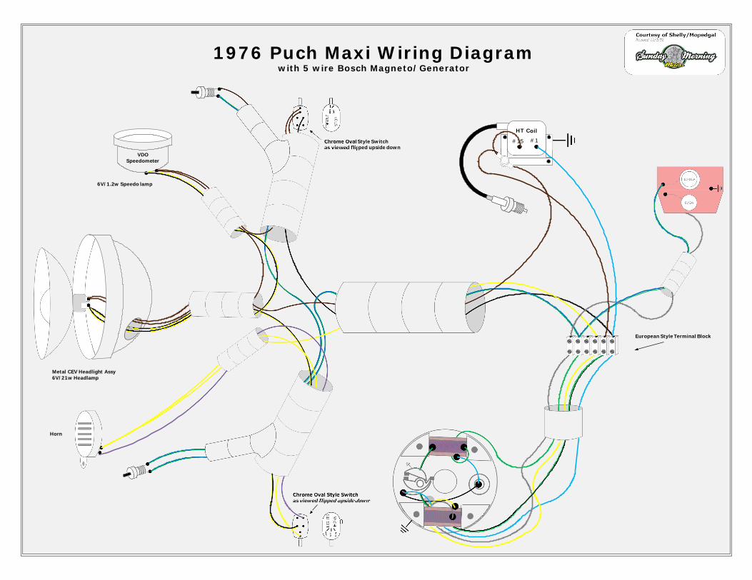
1976 Puch Maxi Wiring Diagramwith 5 wire Bosch Magneto/Generator
VDOSpeedometer
Horn
6v/5w
6v/10w
HT Coil
#15 #1
European Style Terminal Block
Chrome Oval Style Switchas viewed flipped upside down
Chrome Oval Style Switchas viewed flipped upside down
Metal CEV Headlight Assy6V/21w Headlamp
6V/1.2w Speedo lamp
1976 Puch Maxi Wiring Diagramwith 5 wire Bosch Magneto/Generator
VDOSpeedometer
Horn
6v/5w
6v/10w
HT Coil
#15 #1
European Style Terminal Block
Chrome Oval Style Switchas viewed flipped upside down
Chrome Oval Style Switchas viewed flipped upside down
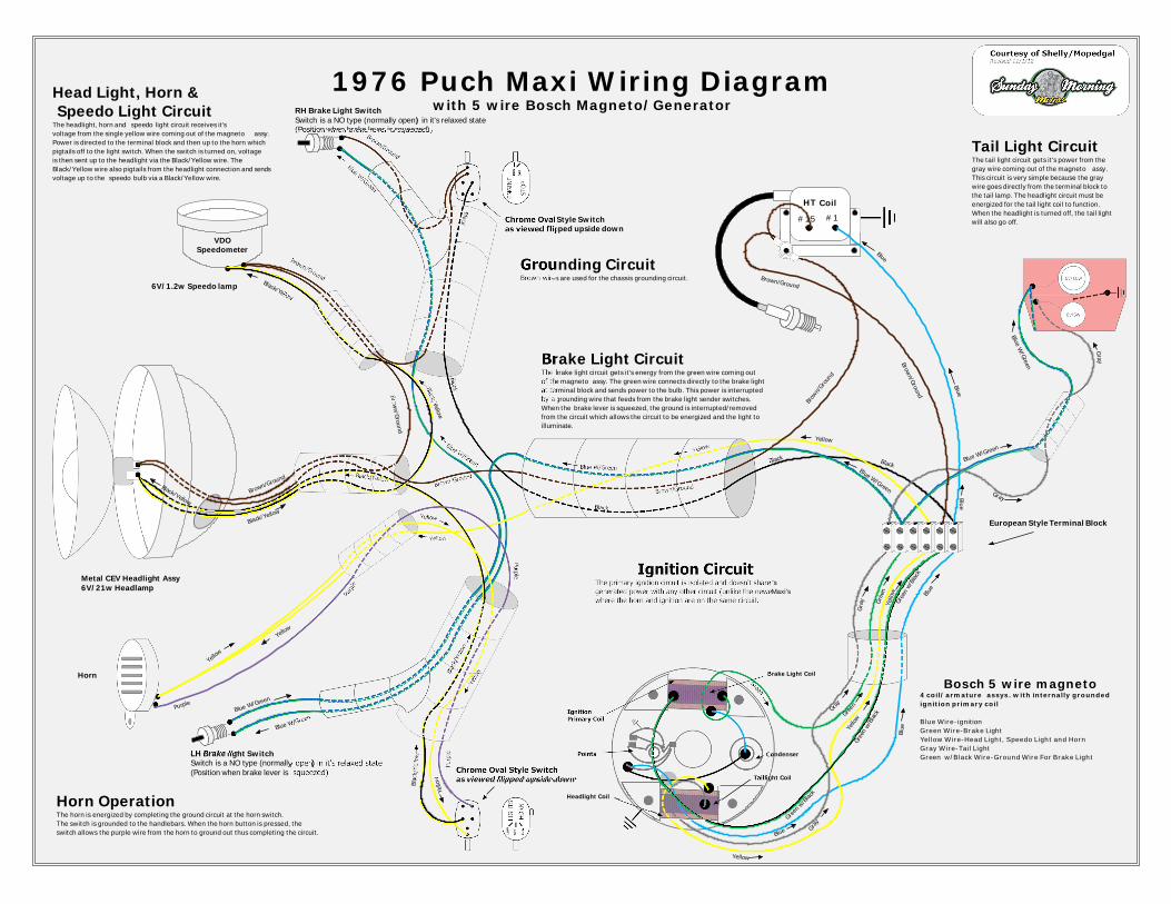
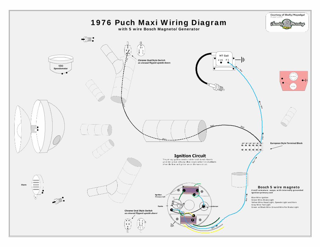
Ignition CircuitThe primary ignition circuit is isolated and doesn't share it'sgenerated power with any other circuit (unlike the newer Maxi'swhere the horn and ignition are on the same circuit.
Bosch 5 wire magneto4 coil/armature assys. with internally groundedignition primary coil
Blue Wire-ignitionGreen Wire-Brake LightYellow Wire-Head Light, Speedo Light and HornGray Wire-Tail LightGreen w/Black Wire-Ground Wire For Brake Light
Blue
CondenserPoints
IgnitionPrimary Coil
Blue
Blue
Blue
Blue
BlackBlack
Black
Black
Black
Blue
Brake Light Coil
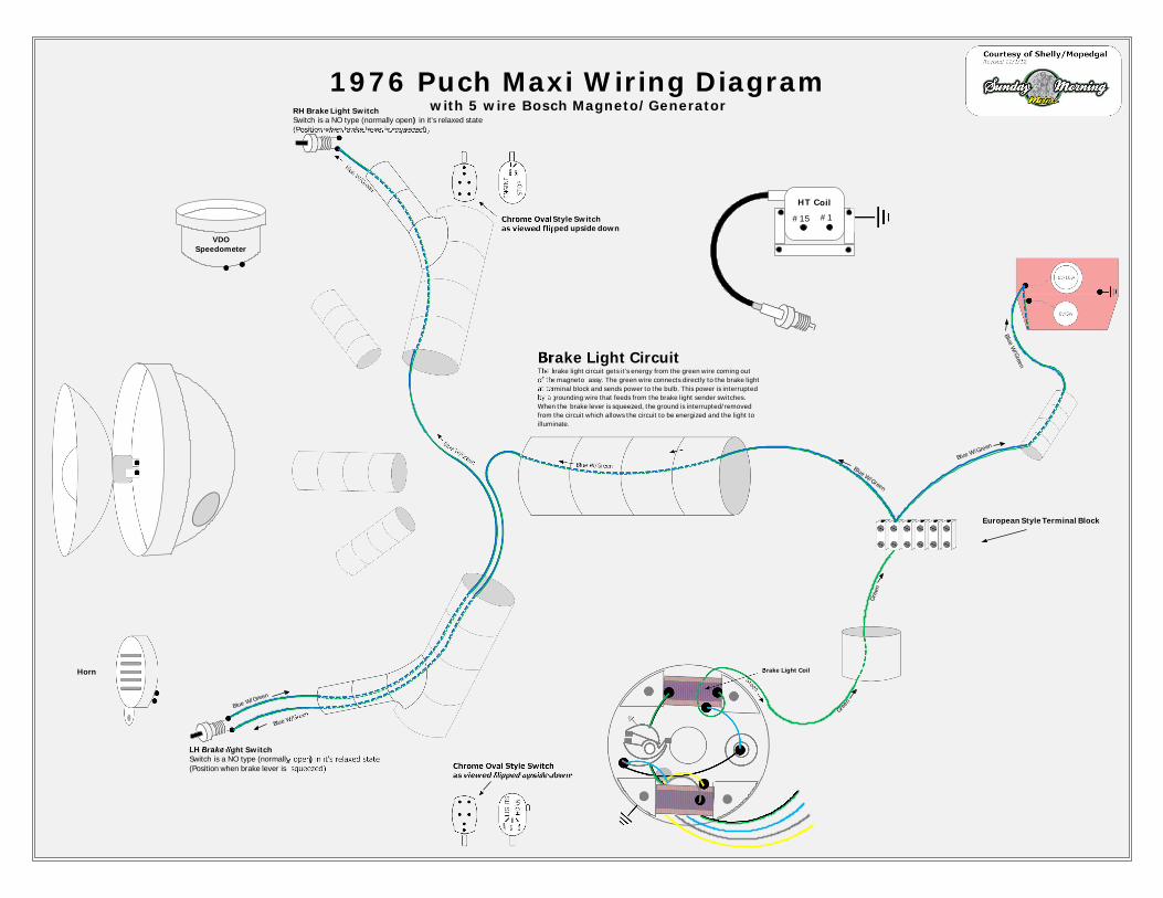
RH Brake Light SwitchSwitch is a NO type (normally open) in it's relaxed state(Position when brake lever is squeezed)
Green
Blue W/GreenBrake Light Circuit
The brake light circuit gets it's energy from the green wire coming outof the magneto assy. The green wire connects directly to the brake lightat terminal block and sends power to the bulb. This power is interruptedby a grounding wire that feeds from the brake light sender switches.When the brake lever is squeezed, the ground is interrupted/removedfrom the circuit which allows the circuit to be energized and the light toilluminate.
LH Brake light SwitchSwitch is a NO type (normally open) in it's relaxed state(Position when brake lever is squeezed)
Gre
en
Blue W/Green
Green
Blue W/Green
Blue W/Green
Blue W/Green
Blue W/Green
Blue W/Green
Blue W/Green
Metal CEV Headlight Assy6V/21w Headlamp
6V/1.2w Speedo lamp
Headlight Coil
Yello
w
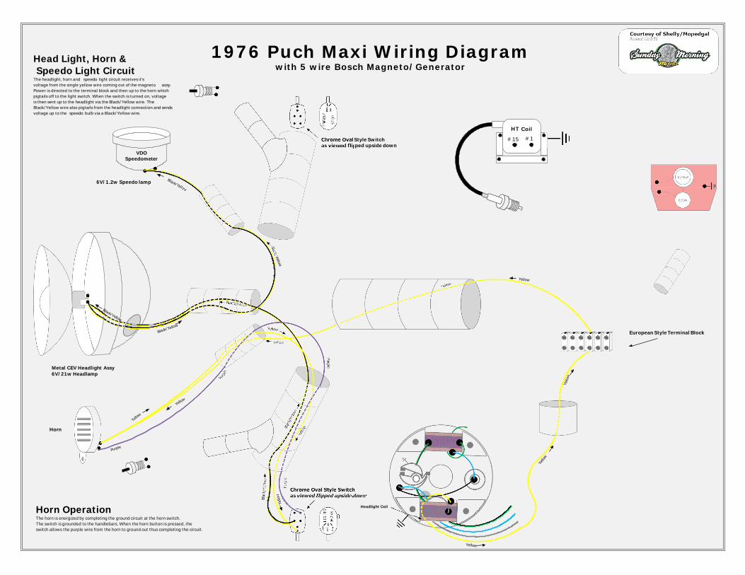
Head Light, Horn &Speedo Light Circuit
The headlight, horn and speedo light circuit receives it'svoltage from the single yellow wire coming out of the magneto assy.Power is directed to the terminal block and then up to the horn whichpigtails off to the light switch. When the switch is turned on, voltageis then sent up to the headlight via the Black/Yellow wire. TheBlack/Yellow wire also pigtails from the headlight connection and sendsvoltage up to the speedo bulb via a Black/Yellow wire.
Yellow
Yel lo
w
Yellow
Horn OperationThe horn is energized by completing the ground circuit at the horn switch.The switch is grounded to the handlebars. When the horn button is pressed, theswitch allows the purple wire from the horn to ground out thus completing the circuit.
Yellow
Yellow
Yellow
Yellow
Yellow
Yello
w
Yello
w
Blac
k/Ye
l low
Blac
k/Ye
llow
Black/Yellow
Black/Yellow
Black/Yellow
Black/Yellow
Black/Yellow
Purple
Purp
le
Purple
Purp
le
Gra
y
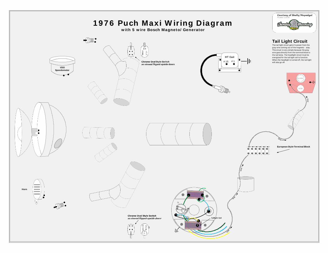
Tail Light CircuitThe tail light circuit gets it's power from thegray wire coming out of the magneto assy.This circuit is very simple because the graywire goes directly from the terminal block tothe tail lamp. The headlight circuit must beenergized for the tail light coil to function.When the headlight is turned off, the tail lightwill also go off.
Taillight Coil
Gray
Gra y
Gray
Gray
Brown/Ground
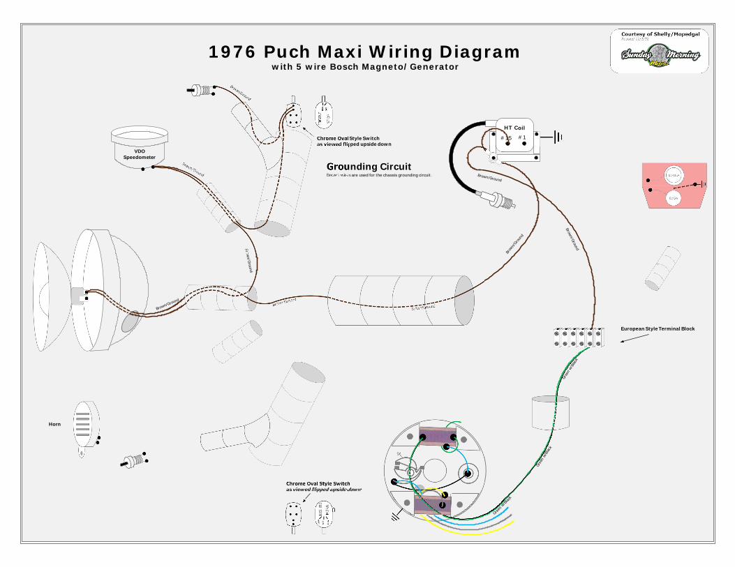
Grounding CircuitBrown wires are used for the chassis grounding circuit.
Gree
nw
/Bla
ck
Gree
nw/
Blac
k
Green
w/Blac
k
Brown/Ground
Br own/ G
round
Brow
n/Gro
und
Brown/Ground
Brown/Ground
Brown/Ground
Brown/Ground
Brown/Ground
1976 Puch Maxi Wiring Diagramwith 5 wire Bosch Magneto/Generator
VDOSpeedometer
Horn
6v/5w
6v/10w
HT Coil
#15 #1
European Style Terminal Block
Chrome Oval Style Switchas viewed flipped upside down
Chrome Oval Style Switchas viewed flipped upside down
Ignition CircuitThe primary ignition circuit is isolated and doesn't share it'sgenerated power with any other circuit (unlike the newer Maxi'swhere the horn and ignition are on the same circuit.
Bosch 5 wire magneto4 coil/armature assys. with internally groundedignition primary coil
Blue Wire-ignitionGreen Wire-Brake LightYellow Wire-Head Light, Speedo Light and HornGray Wire-Tail LightGreen w/Black Wire-Ground Wire For Brake Light
Blue
CondenserPoints
IgnitionPrimary Coil
Blue
Blue
Blue
Blue
BlackBlack
Black
Black
Black
Blue
1976 Puch Maxi Wiring Diagramwith 5 wire Bosch Magneto/Generator
VDOSpeedometer
Horn
6v/5w
6v/10w
HT Coil
#15 #1
European Style Terminal Block
Chrome Oval Style Switchas viewed flipped upside down
Chrome Oval Style Switchas viewed flipped upside down
Metal CEV Headlight Assy6V/21w Headlamp
6V/1.2w Speedo lamp
Headlight Coil
Yello
w
Head Light, Horn &Speedo Light Circuit
The headlight, horn and speedo light circuit receives it'svoltage from the single yellow wire coming out of the magneto assy.Power is directed to the terminal block and then up to the horn whichpigtails off to the light switch. When the switch is turned on, voltageis then sent up to the headlight via the Black/Yellow wire. TheBlack/Yellow wire also pigtails from the headlight connection and sendsvoltage up to the speedo bulb via a Black/Yellow wire.
Yellow
Yel lo
w
Yellow
Horn OperationThe horn is energized by completing the ground circuit at the horn switch.The switch is grounded to the handlebars. When the horn button is pressed, theswitch allows the purple wire from the horn to ground out thus completing the circuit.
Yellow
Yellow
Yellow
Yellow
Yellow
Yello
w
Yello
w
Blac
k/Ye
l low
Blac
k/Ye
llow
Black/Yellow
Black/Yellow
Black/Yellow
Black/Yellow
Black/Yellow
Purple
Purp
le
Purple
Purp
le
1976 Puch Maxi Wiring Diagramwith 5 wire Bosch Magneto/Generator
VDOSpeedometer
Horn
6v/5w
6v/10w
HT Coil
#15 #1
European Style Terminal Block
Chrome Oval Style Switchas viewed flipped upside down
Chrome Oval Style Switchas viewed flipped upside down
Gra
y
Tail Light CircuitThe tail light circuit gets it's power from thegray wire coming out of the magneto assy.This circuit is very simple because the graywire goes directly from the terminal block tothe tail lamp. The headlight circuit must beenergized for the tail light coil to function.When the headlight is turned off, the tail lightwill also go off.
Taillight Coil
Gray
Gra y
Gray
Gray
1976 Puch Maxi Wiring Diagramwith 5 wire Bosch Magneto/Generator
VDOSpeedometer
Horn
6v/5w
6v/10w
HT Coil
#15 #1
European Style Terminal Block
Chrome Oval Style Switchas viewed flipped upside down
Chrome Oval Style Switchas viewed flipped upside down
Brake Light Coil
RH Brake Light SwitchSwitch is a NO type (normally open) in it's relaxed state(Position when brake lever is squeezed)
Green
Blue W/G
reenBrake Light CircuitThe brake light circuit gets it's energy from the green wire coming outof the magneto assy. The green wire connects directly to the brake lightat terminal block and sends power to the bulb. This power is interruptedby a grounding wire that feeds from the brake light sender switches.When the brake lever is squeezed, the ground is interrupted/removedfrom the circuit which allows the circuit to be energized and the light toilluminate.
LH Brake light SwitchSwitch is a NO type (normally open) in it's relaxed state(Position when brake lever is squeezed)
Gre
en
Blue W/Green
Green
Blue W/Green
Blue W/Green
Blue W/Green
Blue W/Green
Blue W/Green
Blue W/Green
1976 Puch Maxi Wiring Diagramwith 5 wire Bosch Magneto/Generator
VDOSpeedometer
Horn
6v/5w
6v/10w
HT Coil
#15 #1
European Style Terminal Block
Chrome Oval Style Switchas viewed flipped upside down
Chrome Oval Style Switchas viewed flipped upside down
Brown/Ground
Grounding CircuitBrown wires are used for the chassis grounding circuit.
Gree
nw/
Blac
k
Gree
nw/
Blac
k
Green
w/Blac
k
Brown/Ground
Br own/ G
round
Brow
n/Gro
und
Brown/Ground
Brown/Ground
Brown/Ground
Brown/Ground
Brown/Ground