(19) United States (12) Patent Application Publication (10 ... · bizu S, Llano-Ponte R, Mondragon...
18
(19) United States (12) Patent Application Publication (10) Pub. No.: US 2013/0273350 A1 Lee et al. US 20130273350A1 (43) Pub. Date: Oct. 17, 2013 (54) NANOCELLULOSE SURFACE COATED SUPPORT MATERAL Inventors: Koon Yang Lee, London (GB); Puja Bharadia, London (GB); Alexander Bismarck, London (GB) Assignee: IMPERIAL INNOVATIONS LIMITED, London (GB) (75) (73) (21) (22) (86) (30) Appl. No.: PCT Fled: PCT NO.: S371 (c)(1), (2), (4) Date: 13/878,986 Oct. 12, 2011 PCT/EP2011/067777 Jul. 1, 2013 Foreign Application Priority Data Oct. 12, 2010 Sep. 27, 2011 it. (GB). (GB). 1017220.3 111663.O.3 : Sis: stirri as :: 83 is 3 SS is kixg: S.23. i?e 8.3: Publication Classification (51) Int. Cl. B32B5/02 (2006.01) (52) U.S. Cl. CPC ........................................ B32B5/02 (2013.01) USPC ...... 428/326; 427/430.1; 427/372.2; 427/439 (57) ABSTRACT The present invention relates to a process for the production of a surface coated Support material wherein said process comprises contacting a Support material with an aqueous dispersion of nanocellulose. The Surface coated Support material can be used in a composite material. The invention therefore further relates to the surface coated support material perse, a composite comprising the material, a process for the production of the composite material and an article produced from the composite material. 8 s Sky 33: A2lric:33 3.3388 as 3333 wox 3 rers st 2, 5.3ky fate is: E. s
Transcript of (19) United States (12) Patent Application Publication (10 ... · bizu S, Llano-Ponte R, Mondragon...
(19) United States (12) Patent Application Publication (10) Pub. No.: US 2013/0273350 A1
Lee et al.
US 20130273350A1
(43) Pub. Date: Oct. 17, 2013
(54) NANOCELLULOSE SURFACE COATED SUPPORT MATERAL
Inventors: Koon Yang Lee, London (GB); Puja Bharadia, London (GB); Alexander Bismarck, London (GB)
Assignee: IMPERIAL INNOVATIONS LIMITED, London (GB)
(75)
(73)
(21)
(22)
(86)
(30)
Appl. No.:
PCT Fled:
PCT NO.:
S371 (c)(1), (2), (4) Date:
13/878,986
Oct. 12, 2011
PCT/EP2011/067777
Jul. 1, 2013
Foreign Application Priority Data
Oct. 12, 2010 Sep. 27, 2011
it.
(GB). (GB).
1017220.3 111663.O.3
: Sis: stirri as :: 83 is 3 SS is kixg: S.23. i?e 8.3:
Publication Classification
(51) Int. Cl. B32B5/02 (2006.01)
(52) U.S. Cl. CPC ........................................ B32B5/02 (2013.01) USPC ...... 428/326; 427/430.1; 427/372.2; 427/439
(57) ABSTRACT
The present invention relates to a process for the production of a surface coated Support material wherein said process comprises contacting a Support material with an aqueous dispersion of nanocellulose. The Surface coated Support material can be used in a composite material. The invention therefore further relates to the surface coated support material perse, a composite comprising the material, a process for the production of the composite material and an article produced from the composite material.
8 s Sky 33: A2lric:33 3.3388 as 3333 wox 3 rers st 2, 5.3ky fate is: E. s
Patent Application Publication Oct. 17, 2013 Sheet 1 of 6 US 2013/0273350 A1
Mo is: x- gress
Figure 1
Patent Application Publication Oct. 17, 2013 Sheet 2 of 6 US 2013/0273350 A1
Figure 2
Patent Application Publication Oct. 17, 2013 Sheet 3 of 6 US 2013/0273350 A1
(a) 3.0 3.0 (b)
Neat PLLA PLLA-sisa 2.5 t BC
-DCNS -SSa s EAESN PLA-DCNS-BC 2.0" s PLA-HFNS-BC
9. 20 W --
i
g 15 E 1.5 d g s s g, 1.0 g 1.0
of 0.5 50.5
O.0 0.0 30 40 50 60 70 80 90 00 30 40 50 60 70 80 90 100
Tenperature (C) Temperature (C)
(d) Neat PLA FLA-sisal PLLA-DCMS PLLA-HFNS
Neat PLA PLLA-sisal-BC PLLA-DCMS-BC PLA-HFNS-BC
30 40 50 SO 70 80 90 100 30 40 50 60 70 8O 90 100 Temperature (C) Tenperature (C)
Figure 3
Patent Application Publication Oct. 17, 2013 Sheet 4 of 6 US 2013/0273350 A1
Dispersion of s:::::::::: ::::::::::
i (+ BC) Sisal fibre mat + 10 wt.% BC
Figure 4
Patent Application Publication Oct. 17, 2013 Sheet 5 of 6 US 2013/0273350 A1
so o so too 150 Temperature (C)
Figure 5
Patent Application Publication Oct. 17, 2013 Sheet 6 of 6 US 2013/0273350 A1
Neat AESO - - - - AESO-sisal a c us x AESO-Sisa-BC
Temperature (C)
Figure 6
US 2013/0273350 A1
NANOCELLULOSE SURFACE COATED SUPPORT MATERAL
0001. The present invention relates to a process for the production of a nanocellulose surface coated Support material 0002 Research interest in utilising natural fibres, such as plant fibres as reinforcement for polymers is re-emerging in the field of engineering. Natural fibres have a number of advantages including their worldwide availability, high spe cific strength and modulus, low density, biodegradability and renewability. A particular application of such reinforced polymers is their use in composite materials. 0003. A composite is a structural product made of two or more distinct components. While each of the components remains physically distinct, composite materials exhibit a synergistic combination of the properties of each component, resulting in a material with extremely favourable and useful characteristics. Composites are generally composed of a matrix component and a reinforcement component. The rein forcement provides the special mechanical and/or physical properties of the material and is provided as fibres or frag ments of material. The matrix surrounds and binds the fibres or fragments together to provide a material which is durable, stable to heat, stable to corrosion, malleable, strong, stiff and light. Composites made with synthetic fillers such as glass or carbon fibres are extensively used for many applications. Such as sport, automotive and aerospace. Their success is due to their specific properties, based on a strong interaction between the different components and a great stability. 0004 The strength and stiffness of a composite material will depend on the strength and stiffness of the reinforcement component and its interaction with the matrix component. A weak mechanical interaction between the reinforcement component and the matrix component results in a composite material with limited practical applications. Improving the interaction of the reinforcement and the matrix components therefore provides composite materials which are stronger, more durable and less Susceptible to stress and wear. 0005. There are however a number of problems associated with the use of natural fibres to reinforce polymers, including the inherent variability in dimensions and mechanical prop erties of the fibres, even within the same cultivation. In addi tion, the use of natural fibres in composites has been limited by their low thermal stability, the resulting reduction in ten sile properties after processing and their inherent hydrophilic nature. Attempts to render natural fibres more hydrophobic (thereby improving the compatibility between hydrophilic natural fibres and hydrophobic polymer matrices) have included silylation (Mehta G, Drzal LT, Mohanty AK, Misra M. JAppl Polym Sci. 2006: 99(3):1055-1068: Ganan P. Gar bizu S, Llano-Ponte R, Mondragon I. Polym Compos. 2005; 26(2): 121-127; Pothan LA, Thomas S. Groeninckx G. Com pos Pt A-Appl Sci Manuf. 2006:37(9): 1260-1269; and Vala dez-Gonzalez A. Cervantes-Uc JM, Olayo R, Herrera-Franco PJ. Compos Pt B-Eng. 1999; 30(3):321-331), acetylation (Tserki V. Zafeiropoulos N E. Simon F, Panayiotou C. Com pos Pt A-Appl Sci Manuf. 2005; 36(8): 1110-1118), benzoy lation (Nair KCM, Thomas S. Groeninckx G. Compos Sci Technol. 2001: 61 (16):2519-2529), maleated coupling agents (Mishra S. Naik J. B. Patil Y P. Compos SciTechnol. 2000; 60(9): 1729-1735), isocyanate treatment (George J, Janardhan R. Anand J S. Bhagawan SS, Thomas S. Polymer. 1996: 37(24):5421-5431) and polymer grafting of natural fibres (Kaith BS, Kalia S. Express Polym Lett. 2008; 2(2): 93-100). While these methods have improved the hydropho
Oct. 17, 2013
bicity of the natural fibres, these chemical treatments involve the use of large amounts of hazardous chemicals and the chemical waste must be handled and disposed of appropri ately. This adds extra cost to the production of (modified) natural fibre reinforced composites. 0006 Cellulose or plant fibres have been used in some applications in the art as reinforcement agents, such as the manufacture of paper. There are a number of Sources of cel lulose fibres. Cellulose microfibrils can be extracted from wood pulp or cotton. Cellulose whiskers called tunicin can also be extracted from tunicate, a sea animal. Finally, bacte rial cellulose or nanocellulose can be produced by specific bacteria strains, the most efficient producer being Aceto bacter xylinum. 0007. The present invention provides a novel process for the production of a material reinforced with nanocellulose. 0008. The first aspect of the invention therefore provides a process for the production of a surface coated Support mate rial; comprising
0009 contacting a support material with an aqueous dispersion of nanocellulose.
0010. It will be appreciated that the nanocellulose for the purposes of this invention is isolated nanocellulose (i.e. where the nanocellulose is bacterial cellulose, the support material is contacted with an aqueous dispersion of bacterial cellulose in the absence of a cellulose producing microorgan ism). The nanocellulose is therefore extracted, isolated and/or purified prior to the formation of the aqueous nanocellulose dispersion. 0011 For the purposes of this invention, nanocellulose is crystalline cellulose with at least one dimension (i.e. height, length or depth) smaller than 100 nm. The source of the nanocellulose is not limited. The nanocellulose can therefore be extracted from a plant, such as wood pulp or cotton or can be extracted from an animal Such as tunicate. Alternatively, cellulose can be produced by bacteria. The nanocellulose can be provided as nanofibrillated cellulose, cellulose nanowhis kers or bacterial cellulose. 0012. The nanocellulose can be purified prior to its contact with the support material. Where the nanocellulose is bacte rial cellulose, the bacteria cellulose can be purified by treat ment with basic conditions to remove all microorganisms. Alternatively, the cellulose can be purified by centrifugation. 0013 The nanocellulose can be extracted from a source thereof for example a foodstuff such as Nata-de-coco or can be isolated from a bacterial culture of a cellulose producing microorganism. Examples of Such a cellulose producing micro-organism include micro-organisms belonging to the genera, Acetobacter, Rhizobium, Alcaligenes, Agrobacte rium, Sarcina and/or Pseudomonas. The micro-organism can be a strain adapted to culture in agitated conditions, such as Acetobacter xylinum BPR2001. 0014. The shape and size of the cellulose will depend on the source of the cellulose. The cellulose is preferably pro vided as a nanofibre having a thickness of from 0.5 to 50 nm, preferably from 1 to 20 nm, more preferably from 2 to 10 nm, most preferably 1, 2, 3, 4, 5, 6, 7, 8, 9 or 10 nm. The cellulose fibre preferably has a width of from 0.5 to 100 nm, preferably 1 to 50 nm, more preferably 5 to 20 nm. The cellulose fibre preferably has a length of 0.5 micrometres to 1000 microme tres, preferably 1 micrometres to 500 micrometres, more preferably 5 to 300 micrometres, most preferably 10 to 150 micrometres. The cellulose is preferably produced as a nanofibre, such as a ribbon shaped nanofibril
US 2013/0273350 A1
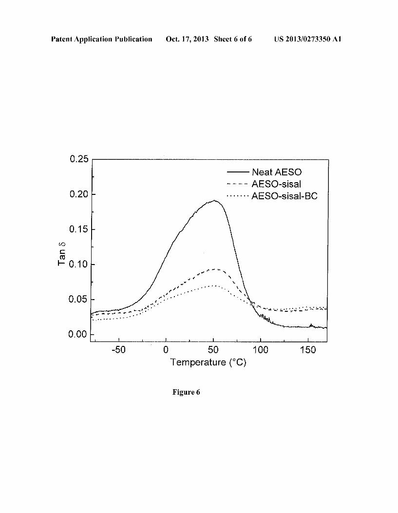
0015 The nanocellulose is provided in the form of an aqueous dispersion, Suspension or a slurry. Thus, the majority of the nanocellulose will not dissolve in the aqueous solution. The dispersion can be prepared by mixing the nanocellulose with an aqueous solution, for example water. The nanocellu lose can be mixed with the water by agitation, for example by stirring, Sonication, colloid milling, grinding or homogenisa tion. 0016. The support is contacted with the aqueous disper sion of nanocellulose, preferably the Support is immersed or dipped in the aqueous dispersion of nanocellulose (i.e. by slurry dipping). The Support is preferably brought into con tact with the aqueous dispersion of nanocellulose at room temperature for a period of from 1 to 2 hours, to 7 days, for example from 1 to 7 days, such as 2 to 5 days, preferably 3 days. It will be appreciated by a person skilled in the art that the time required to allow coating of the Support will depend on the hydrophilicity and/or water uptake of the Support. As a general guide, the minimum amount of time required will be the time required to obtain maximum moisture Saturation of the Support when immersed in water. 0017. The support is provided as a polymer. In particular, the Support can be provided as a pellet, a powder, loose fibres, a woven or non-woven fibre mat, a string or a tow. The polymer is preferably a reinforcement component or matrix component as used in the art for the manufacture of composite materials. For the purposes of this invention, the Support is preferably a hydrophilic support. 0018. The support is preferably provided in the form of a fibre, pellet or a powder, more preferably as a fibre. The polymer can be a synthetic polymer or a naturally derived or occurring polymer. In particular, the polymer may be a natu rally occurring fibre or a synthetic polymer based fibre. For the purposes of this invention, the polymer is preferably a hydrophilic polymer (i.e. the polymer provides hydrogen bonding sites). 0019. The polymer can be a synthetic bioderived polymer Such as poly(lactic acid) (PLA), polyhydroxyalkanoate (PHA), bacterial polyesters or synthetic, semi-synthetic or modified cellulose polymers such as cellulose acetate butyrate (CAB), cellulose butyrate, polypropylene (PP), polystyrene (PS), polymethylmetharylate (PMMA), Lyocell or rayon. The polymer can be a naturally occurring polymer Such as wheat gluten, corn Zein, wool, cellulose or starch. The fibre can be derived or obtained from a plant or animal. In particular, the fibre is preferably extracted from a plant, such as one or more of abaca, bamboo, banana, coir, coconut husk, cotton, flax, henequen, hemp, hop, jute, palm, ramie or sisal. Most preferably the fibre is a sisal fibre 0020. Where the support is obtained or derived from a natural source, the support can be biodegradable. It will be appreciated that the provision of a reinforced biodegradable material will provide benefits, particularly when used incom posite materials. 0021. After immersion of the support, it may be removed from the aqueous dispersion of bacterial cellulose and dried. In one embodiment, the process of the first aspect of further comprises the steps of
0022 removing the coated support material from the dispersion; and
0023 optionally drying the support material. 0024. The step of removing the coated support material from the dispersion may be achieved by mechanical extrac tion of the Support, for example, by using tweezers. The
Oct. 17, 2013
Support material can be dried according to any methods known in the art, for example, air drying, oven drying, freeze drying, drying in vacuo, infra-red irradiation etc. The method by which the Support material is dried can impact on the orientation and arrangement of the bacterial cellulose coating on the support material, and can therefore be modified to manipulate the form of the material produced by the first aspect of the invention. 0025. In a particular embodiment of the first aspect, the surface coated support material is dried with heating. Prefer ably, the Support material is dried above room temperature, for example at a temperature of from 50° C. to 150° C. preferably 60° C., 70° C., 80° C., 90° C., 100° C., 110° C., 120° C., 130° C. or 140°C. The drying temperature can be provided as a range of temperatures selected from any of the discrete temperatures set out above, for example 70° C. to 90° C. The drying can be carried our in air or under a vacuum. The drying of the Support material results in a dense nanocellulose layer on the surface of the material. The first aspect of the invention therefore provides a process for the production of a Surface coated Support material; comprising
0026 contacting a Support material with an aqueous dispersion of nanocellulose;
0027 removing the coated support material from the dispersion; and
0028 drying the support material at 70° C. to 90° C., preferably at 80° C. wherein the nanocellulose is pro vided as a bacterial cellulose layer on the surface of the support material, preferably wherein the bacterial cellu lose layer is a dense layer of bacterial cellulose. In a dense layer, the bacterial cellulose may form a layer which Substantially covers the Support material.
0029. Alternatively, the surface coated support material is initially partially dried by layering the Support material between two pieces of an absorbent material, such as filter paper. Pressure can be applied to the upper and/or lowerpiece of absorbent material, for example by the addition of a weight to increase the removal of liquid from the Support material. The support material can then be further dried, at a tempera ture of 30 to 150° C., preferably 40°C., 50° C., 60° C., 70° C., 80°C, 90° C., 100° C., 110° C., 120° C., 130° C. or 140° C. The drying temperature can be provided as a range of tem peratures selected from any of the discrete temperatures set out above, for example, 30° C. to 50° C. The drying is pref erably carried out in an air oven. This two stage drying method results in the formation of hairy “fibres’ or a hairy Support, where the nanocellulose is orientated perpendicu larly to the surface of the support material. The first aspect of the invention therefore further provides a process for the production of a Surface coated Support material; comprising
0030 contacting a Support material with an aqueous dispersion of nanocellulose;
0.031 removing the coated support material from the dispersion; and
0032) drying the support material by layering the Sup port material between two pieces of absorbent material followed by drying in an air oven at 30° C. to 50° C., preferably at 40° C.;
wherein the nanocellulose of the coating is orientated perpen dicularly to the Support Surface. 0033. In certain embodiments of a method comprising the steps of
0034 removing the coated support material from the dispersion; and
0035 optionally drying the support material, the removing step is carried out by filtration of the dispersion, for example vacuum filtration, or by evaporation, for example under reduced pressure (i.e. under vacuum) and/or heating.
US 2013/0273350 A1
0036. It will be appreciated by the skilled person that the steps of removing the coated Support material from the dis persion and drying the coated Support material may be carried out in a single step for example, by evaporation (e.g. by heating and/or under reduced pressure). For example, the dispersion comprising the coated Support material may be heated to remove the coated support material from the dis persion by evaporation and to dry the Support material. 0037. When the coated support material is removed from the dispersion by filtration, for example, by vacuum filtration, the Support material may be bound together by the nanocel lulose (i.e. forming a body comprising coated Support mate rial bound by the nanocellulose). In embodiments where the coated Support material is removed from the dispersion by filtration, the support material may be initially partially dried by layering the Support material between two pieces of an absorbent material, such as filter paper. Pressure can be applied to the upper and/or lower piece of absorbent material, for example by the addition of a weight to increase the removal of liquid from the Support material. The Support material may be further dried, at a temperature of 30 to 150° C., preferably 40° C., 50° C., 60° C., 70° C., 80° C., 90° C., 100° C., 110° C., 120° C., 130° C. or 140° C. The drying temperature can be provided as a range of temperatures selected from any of the discrete temperatures set out above, for example, 50° C. to 70° C. The first aspect of the invention therefore further provides a process for the production of a Surface coated Support material; comprising
0038 contacting a support material with an aqueous dispersion of nanocellulose;
0039 removing the coated support material from the dispersion by filtration of the dispersion;
0040 drying the support material by layering the Sup port material between two pieces of absorbent material; and
0041 optionally drying in an air oven at 50° C. to 70° C., preferably at 60° C.
0042. The modified material can be stored at room tem perature and pressure. 0043. It has been found that the production of either a dense nanocellulose coating layer on the Surface of the Sup port material or nanocellulose coated hairy fibres, in which the nanocellulose is oriented perpendicularly to the surface of the Support material results in an increase in Surface area of the support material when compared with the unmodified Support material. 0044. In a preferred feature of the first aspect of the inven
tion, the Support can be modified by physical or chemical treatments prior to contact with the nanocellulose, such as atmospheric or low pressure plasma or corona treatments, Solvent washing or extraction, bleaching, boiling or washing, for example in a basic solution, Such as Sodium hydroxide Solution. In particular, the Support can be washed with a Solvent, such as an organic solvent (i.e. acetone, ethyl acetate etc. or an alcohol Such as ethanol, methanol, propanol, butanol etc.) prior to exposing the Support to an aqueous Suspension or slurry of nanocellulose. 0045. The second aspect of the invention relates to a sur face coated support material obtainable by the process of the first aspect of the invention. Preferably the surface coated Support material is obtained by the process of the first aspect of the invention.
Oct. 17, 2013
0046. In particular, the second aspect of the invention relates to a Support material Surface coated with nanocellu lose, wherein the nanocellulose is provided as a dense nano cellulose coating. 0047 Alternatively, the second aspect of the invention relates to a Support material Surface coated with nanocellu lose, wherein the nanocellulose of the coating is orientated perpendicular to the Support Surface. 0048 Alternatively, the second aspect of the invention relates to a Support material Surface coated with nanocellu lose, wherein the support material is bound together by the nanocellulose. 0049. The third aspect of the invention relates to a com posite material comprising a reinforcement and a matrix wherein the reinforcement comprises a surface coated Sup port material obtainable or obtained by the process of the first aspect of the invention. The composite material of the third aspect is a cellulose nanocomposite. 0050. In a preferred embodiment of the third aspect of the invention, the matrix comprises cellulose. The cellulose is preferably dispersed through the matrix. 0051. The material obtainable by the process of the first aspect can be used as a reinforcing agent for composite manu facturing. The material can therefore be combined with any conventional matrix known to a person skilled in the art. Where the material is biodegradable, in order to preserve the renewability and biodegradability of the material, bioderived polymers such as poly(lactic acid) (PLA), polyhydroxyal kanoates (PHA, bacterial polyesters), polycarbonates, or modified cellulose polymers (cellulose acetate butyrate (CAB) or cellulose butyrate) or cellulose pulp, as well as epoxy resins such as plant based resins (for example acrylated epoxidised soybean oil (AESO) or epoxidised linseed oil) can be used as a matrix. 0052. In a particularly preferred embodiment, the surface coated Support material is used as a reinforcement for a poly lactide, for example poly-L-lactide (PLLA) to create green hierarchical composites. The increased surface area of the Surface coated Support material increases the Surface rough ness of the Surface coated Support material and results in enhanced mechanical interlocking between the fibres and the matrix. The resulting composite exhibits improved mechani cal properties, tensile properties, visco-elastic properties and flexural properties of the hierarchical composites compared with neat PLLA. 0053 Alternatively, the third aspect of the invention relates to a composite material comprising a reinforcement and a matrix wherein the matrix comprises a Surface coated support material obtainable or obtained by the process of the first aspect of the invention. The matrix comprising the mate rial produced by the process of the first aspect of the invention can be combined with any conventional reinforcement known to a person skilled in the art. Where the matrix is biodegrad able, the reinforcement is preferably also biodegradable. 0054 The fourth aspect of the invention relates to a pro cess for the production of a composite material according to the third aspect of the invention wherein a reinforcement comprising the Surface coated Support material obtainable by the first or of the second aspect is impregnated, mixed, or extruded with a matrix, Such as a polymer or a resin. In certain embodiments, the Surface coated Support material is a Surface coated Support material wherein the Support material is bound together by nanocellulose. The composite can be manufac tured using any Suitable process Such as resin transfer moul
US 2013/0273350 A1
ding, sheet moulding, resin infusion moulding, or by powder impregnation, injection moulding and compression mould ing. For example, the Surface coated Support material may be impregnated with a resin, Such as acrylated epoxidised soy bean oil (AESO) or epoxidised linseed oil and then cured, for example, by heating, optionally in the presence of an initiat ing species. In another example, the Surface coated Support material may be dispersed in a solution of a polymer, Such as PLA, after which the solvent may be removed. Alternatively, the Surface coated Support material may be impregnated, mixed, or extruded with a polymer powder or a polymer fibre, preferably a thermoplastic polymer, allowing the composite material to be heat formed or consolidated into a desired shape. 0055. The fourth aspect of the invention alternatively relates to a process for the production of a composite material according to the third aspect of the invention wherein a rein forcement is impregnated, mixed, or extruded with a matrix comprising the Surface coated Support material obtainable by the first or of the second aspect. The composite can be manu factured using any suitable process such as resin transfer moulding, sheet moulding, resin infusion moulding, or by powder impregnation, injection moulding and compression moulding. 0056. The fifth aspect of the invention relates to a process for the production of a composite material comprising a rein forcement and a matrix wherein the reinforcement comprises a Surface coated Support material, wherein the composite material is produced by:
0057 contacting a support material with an aqueous dispersion of nanocellulose, wherein the aqueous dis persion of nanocellulose further comprises a matrix material;
0.058 removing the composite material from the disper sion by filtration, preferably vacuum filtration; and
0059 optionally drying the composite material. 0060. In certain embodiments, the matrix material is dis persed in the aqueous dispersion of nanocellulose. In other embodiments, the matrix material is a polymer, preferably a thermoplastic polymer. In another embodiment, the matrix material is a polymer powder or a polymer fibre. The matrix material may be a matrix as described in respect of the third aspect of the invention. The composite materials produced by this method may Subsequently be moulded into a desired shape, for example by compression moulding or hot pressing. The Support material and the drying step may be as described in respect of the first aspect. 0061 The sixth aspect of the invention relates to an article produced from the composite material of the third aspect of the invention or a composite material produced by the process of the fourth aspector the fifth aspect. The composite material is particularly provided for use in low-load applications, including but not limited to packaging, or use in the automo tive, household, sport and/or construction industries. The article of the sixth aspect is preferably produced from a fully biodegradable composite material. 0062 All preferred features of each of the aspects of the invention apply to all other aspects mutatis mutandis.
DEFINITIONS
0063 A dense layer of nanocellulose is a support material coated with nanocellulose wherein the nanocellulose fibres are Sufficiently orientated along the Surface of the Support material to form a substantially continuous layer. It will be
Oct. 17, 2013
appreciated that the dense layer can be composed of nanocel lulose fibres stacked or layered on top of one another, where those fibres closest to the support will have at least a portion of the longitudinal axis of the fibre in contact with the support (i.e. they are Support contacting fibres). Further nanocellulose fibres may be stacked or layered on the Support contacting fibres to increase the thickness of the dense layer on the support. These further fibres may not be in contact with the Support material. 0064. The support material of the invention is therefore coated with nanocellulose, wherein a portion of the coating is in contact with the support surface and wherein the fibres of the portion of the coating in contact with the Support Surface have at least a part or portion of their longitudinal axis in contact with the Support Surface. 0065. In the dense layer, the support contacting fibres are orientated so that at least a portion of the longitudinal axis of the fibres is in contact with the surface of the support. The fibres can lie entirely in alignment (and therefore in contact) with the surface. In this case, substantially all of the longitu dinal axis of the fibres is in contact with the surface of the support. Alternatively, the fibres can be in contact with the Support but not lie entirely in alignment. In this case, a portion of the longitudinal axis of the fibre is in contact with the surface. The fibres are in contact with the support and with each other Such that a continuous layer is formed. A dense layer encompasses the provision of the fibres in an extended form and/or where the fibres are folded.
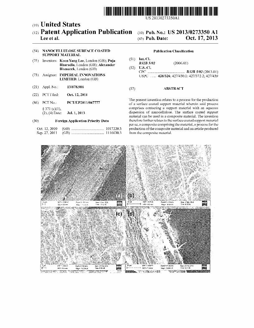
0066. A hairy fibre or a hairy support is a support material coated with nanocellulose where at least a portion of the nanocellulose is orientated perpendicularly to the Surface of the support material. Where nanocellulose of the coating is “orientated perpendicularly’, in the context of this disclosure, it is meant that some, or in some embodiments Substantially all, of the nanocellulose, rather than lying in alignment with the Surface of the Support material, extends at an angle there from (this encompasses not only nanocellulose extending at an angle of 90 degrees relative to the surface of the support material, but also encompasses nanocellulose which extends at any angle therefrom, rather than lying entirely in alignment with the surface). 0067. The surface morphology of a support material (i.e. whether it is coated in hairy fibres or a dense layer) can be determined by visually inspecting the Surface of the Support material, for example by Scanning electron microscopy (SEM). As set out in FIG. 1(d), the hairy fibres extend from the Surface of the Support material. Conversely, as set out in FIGS. 1(b) and (c), the fibres of the dense layer form a coating layer on the Surface of the Support material. 0068 A surface coated support material is a support mate
rial, some or preferably substantially all of the surface of which is coated with nanocellulose. This is intended to encompass a Support material coated with a dense and a hairy support as described above. This term is also intended to encompass a Support material wherein nanocellulose coats the Support material and also acts as a binder to bind Support material together. Thus, a Surface coated Support material encompasses a body comprising Support material bound together by nanocellulose. 0069. The invention may be put into practice in various ways and a number of specific embodiments will be described by way of example to illustrate the invention with reference to the accompanying drawings, in which:
US 2013/0273350 A1
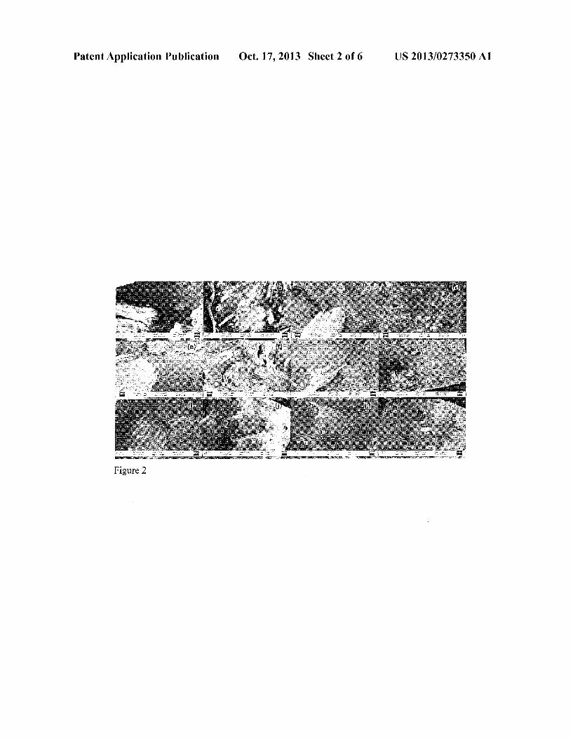
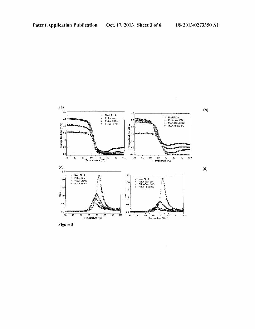
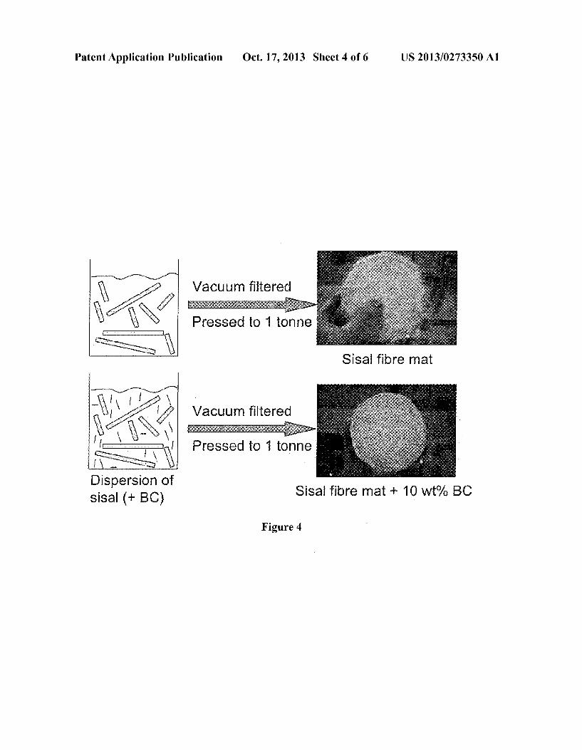
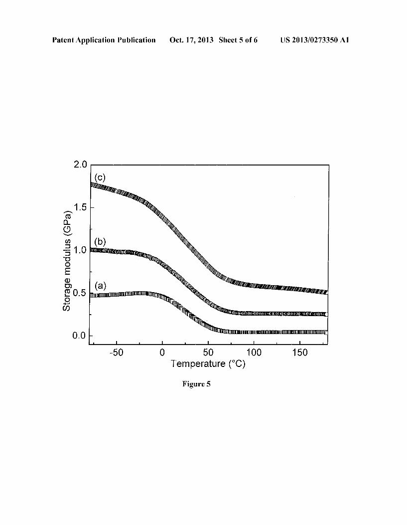
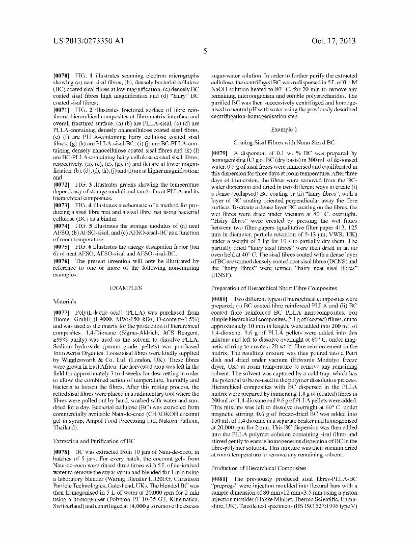
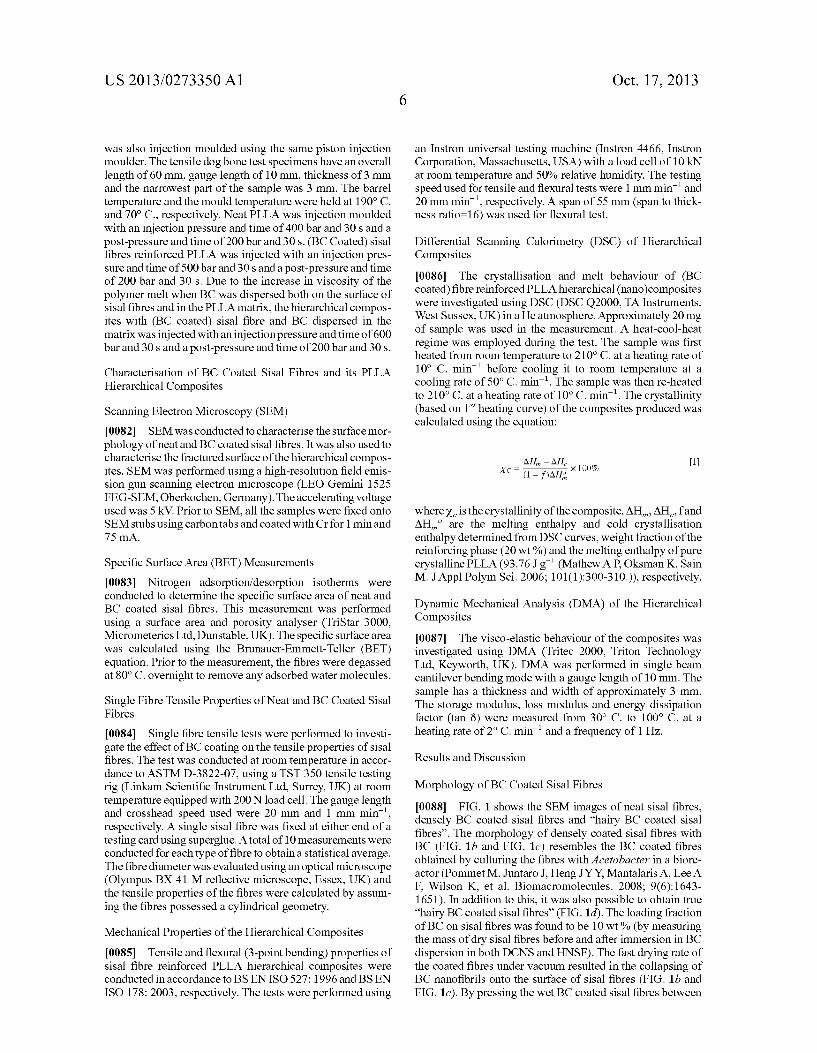
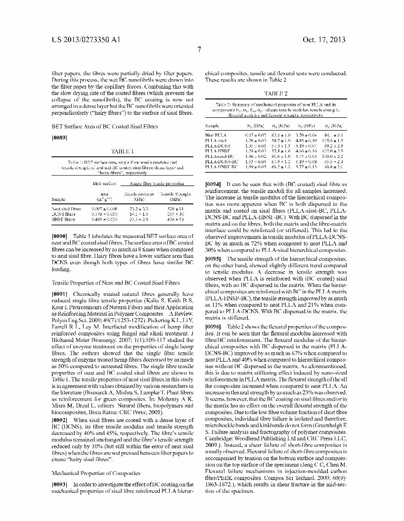
0070 FIG. 1 illustrates scanning electron micrographs showing (a) neat sisal fibres, (b), densely bacterial cellulose (BC) coated sisal fibres at low magnification, (c) densely BC coated sisal fibres high magnification and (d) “hairy BC coated sisal fibres; (0071 FIG. 2 illustrates fractured surface of fibre rein forced hierarchical composites at fibre-matrix interface and overall fractured surface. (a) (b) are PLLA-sisal, (c) (d) are PLLA-containing densely nanocellulose coated sisal fibres, (e) (f) are PLLA-containing hairy cellulose coated sisal fibres, (g) (h) are PLLA-sisal-BC, (i) () are BC-PLLA-con taining densely nanocellulose coated sisal fibres and (k)(1) are BC-PLLA-containing hairy cellulose coated sisal fibres, respectively. (a), (c), (e), (g), (i) and (k) are at lower magni fication. (b), (d), (f), (h), () and (l) are at higher magnification; and 0072 FIG. 3 illustrates graphs showing the temperature dependency of storage moduli and tan 8 of neat PLLA and its hierarchical composites. 0073 FIG. 4 illustrates a schematic of a method for pro ducing a sisal fibre mat and a sisal fibre mat using bacterial cellulose (BC) as a binder. 0074 FIG. 5 illustrates the storage modulus of (a) neat AESO, (b) AESO-sisal, and (c) AESO-sisal-BC as a function of room temperature. 0075 FIG. 6 illustrates the energy dissipation factor (tan 6) of neat AESO, AESO-sisal and AESO-sisal-BC. 0076. The present invention will now be illustrated by reference to one or more of the following non-limiting examples.
EXAMPLES
Materials
0077 Poly(L-lactic acid) (PLLA) was purchased from Biomer GmbH (L9000, MW-150 kDa, D-contents 1.5%) and was used as the matrix for the production of hierarchical composites. 1,4-Dioxane (Sigma-Aldrich, ACS Reagent, >99% purity) was used as the solvent to dissolve PLLA. Sodium hydroxide (purum grade, pellets) was purchased from Acros Organics. Loose sisal fibres were kindly Supplied by Wigglesworth & Co. Ltd. (London, UK). These fibres were grown in East Africa. The harvested crop was left in the field for approximately 3 to 4 weeks for dew retting in order to allow the combined action of temperature, humidity and bacteria to loosen the fibres. After this retting process, the retted sisal fibres were placed in a rudimentary tool where the fibres were pulled out by hand, washed with water and Sun dried for a day. Bacterial cellulose (BC) was extracted from commercially available Nata-de-coco (CHAOKOH coconut gel in syrup, Ampol Food Processing Ltd, Nakorn Pathom, Thailand).
Extraction and Purification of BC
0078 BC was extracted from 10 jars of Nata-de-coco, in batches of 5 jars. For every batch, the coconut gels from Nata-de-coco were rinsed three times with 5 L of de-ionised water to remove the Sugar syrup and blended for 1 min using a laboratory blender (Waring Blender LB2OEG, Christison Particle Technologies, Gateshead, UK). The blended BC was then homogenised in 5 L of water at 20,000 rpm for 2 min using a homogeniser (Polytron PT 10-35 GT, Kinematica, Switzerland) and centrifuged at 14,000 g to remove the excess
Oct. 17, 2013
sugar-water solution. In order to further purify the extracted cellulose, the centrifuged BC was redispersed in 5 L of 0.1 M NaOH solution heated to 80° C. for 20 min to remove any remaining microorganism and soluble polysaccharides. The purified BC was then Successively centrifuged and homoge nised to neutral pH with water using the previously described centrifugation-homogenisation step.
Example 1
Coating Sisal Fibres with Nano-Sized BC (0079 A dispersion of 0.1 wt % BC was prepared by homogenising 0.3 g of BC (dry basis) in 300 mL of de-ionised water. 0.5g of sisal fibres were immersed and equilibrated in this dispersion for three days at room temperature. After three days of immersion, the fibres were removed from the BC water dispersion and dried in two different ways to create (i) a dense (collapsed) BC coating or (ii) “hairy fibres', with a layer of BC coating oriented perpendicular away the fibre surface. To create a dense layer BC coating on the fibres, the wet fibres were dried under vacuum at 80° C. overnight. “Hairy fibres' were created by pressing the wet fibres between two filter papers (qualitative filter paper 413, 125 mm in diameter, particle retention of 5-13 lum, VWR, UK) under a weight of 3 kg for 10 s to partially dry them. The partially dried “hairy sisal fibres’ were then dried in an air oven held at 40°C. The sisal fibres coated with a dense layer of BC are termed densely coated neat sisal fibres (DCNS) and the “hairy fibres' were termed "hairy neat sisal fibres' (HNSF).
Preparation of Hierarchical Short Fibre Composites
0080. Two different types of hierarchical composites were prepared: (i) BC coated fibre reinforced PLLA and (ii) BC coated fibre reinforced BC PLLA nanocomposites. For simple hierarchical composites, 2.4 g of (coated) fibres, cut to approximately 10 mm in length, were added into 200 mL of 1,4-dioxane. 9.6 g of PLLA pellets were added into this mixture and left to dissolve overnight at 60° C. under mag netic stirring to create a 20 wt % fibre reinforcement in the matrix. The resulting mixture was then poured into a Petri dish and dried under vacuum (Edwards Modulyo freeze dryer, UK) at room temperature to remove any remaining solvent. The solvent was captured by a cold trap, which has the potential to be re-used in the polymer dissolution process. Hierarchical composites with BC dispersed in the PLLA matrix were prepared by immersing 1.8g of (coated) fibres in 200 mL of 1,4-dioxane and 9.6 g of PLLA pellets were added. This mixture was left to dissolve overnight at 60° C. under magnetic stirring. 0.6 g of freeze-dried BC was added into 150 mL of 1,4 dioxane in a separate beaker and homogenised at 20,000 rpm for 2 min. This BC dispersion was then added into the PLLA polymer Solution containing sisal fibres and stirred gently to ensure homogeneous dispersion of BC in the fibre-polymer solution. This mixture was then vacuum dried at room temperature to remove any remaining solvent.
Production of Hierarchical Composites I0081. The previously produced sisal fibres-PLLA-BC “prepregs' were injection moulded into flexural bars with a sample dimension of 80 mm x 12 mmx3.5 mm using a piston injection moulder (Hakke Minijet, Thermo Scientific, Hamp shire, UK). Tensile test specimens (BSISO 527:1996 type V)
US 2013/0273350 A1
was also injection moulded using the same piston injection moulder. The tensile dog bone test specimens have an overall length of 60 mm, gauge length of 10 mm, thickness of 3 mm and the narrowest part of the sample was 3 mm. The barrel temperature and the mould temperature were held at 190° C. and 70° C., respectively. Neat PLLA was injection moulded with an injection pressure and time of 400 bar and 30s and a post-pressure and time of 200 bar and 30s. (BCCoated) sisal fibres reinforced PLLA was injected with an injection pres sure and time of 500 bar and 30s and a post-pressure and time of 200 bar and 30s. Due to the increase in viscosity of the polymer melt when BC was dispersed both on the surface of sisal fibres and in the PLLA matrix, the hierarchical compos ites with (BC coated) sisal fibre and BC dispersed in the matrix was injected with an injection pressure and time of 600 bar and 30s and a post-pressure and time of 200 bar and 30s.
Characterisation of BC Coated Sisal Fibres and its PLLA Hierarchical Composites
Scanning Electron Microscopy (SEM) 0082 SEM was conducted to characterise the surface mor phology of neat and BC coated sisal fibres. It was also used to characterise the fractured surface of the hierarchical compos ites. SEM was performed using a high-resolution field emis sion gun scanning electron microscope (LEO Gemini 1525 FEG-SEM, Oberkochen, Germany). The accelerating voltage used was 5 kV. Prior to SEM, all the samples were fixed onto SEM stubs using carbon tabs and coated with Crfor 1 minand 75 mA.
Specific Surface Area (BET) Measurements 0083) Nitrogen adsorption/desorption isotherms were conducted to determine the specific Surface area of neat and BC coated sisal fibres. This measurement was performed using a surface area and porosity analyser (TriStar 3000, Micrometerics Ltd, Dunstable, UK). The specific surface area was calculated using the Brunauer–Emmett–Teller (BET) equation. Prior to the measurement, the fibres were degassed at 80°C. overnight to remove any adsorbed water molecules.
Single Fibre Tensile Properties of Neat and BC Coated Sisal Fibres
0084. Single fibre tensile tests were performed to investi gate the effect of BC coating on the tensile properties of sisal fibres. The test was conducted at room temperature in accor dance to ASTM D-3822-07, using a TST 350 tensile testing rig (Linkam Scientific Instrument Ltd, Surrey, UK) at room temperature equipped with 200 N load cell. The gauge length and crosshead speed used were 20 mm and 1 mm min', respectively. A single sisal fibre was fixed at either end of a testing card using Superglue. A total of 10 measurements were conducted for each type offibre to obtain a statistical average. The fibre diameter was evaluated using an optical microscope (Olympus BX 41 M reflective microscope, Essex, UK) and the tensile properties of the fibres were calculated by assum ing the fibres possessed a cylindrical geometry.
Mechanical Properties of the Hierarchical Composites 0085 Tensile and flexural (3-point bending) properties of sisal fibre reinforced PLLA hierarchical composites were conducted in accordance to BS EN ISO 527: 1996 and BS EN ISO 178: 2003, respectively. The tests were performed using
Oct. 17, 2013
an Instron universal testing machine (Instron 4466. Instron Corporation, Massachusetts, USA) with a load cell of 10 kN at room temperature and 50% relative humidity. The testing speed used for tensile and flexural tests were 1 mm min' and 20 mm min', respectively. A span of 55 mm (span to thick ness ratio=16) was used for flexural test.
Differential Scanning Calorimetry (DSC) of Hierarchical Composites
I0086. The crystallisation and melt behaviour of (BC coated) fibre reinforced PLLA hierarchical (nano)composites were investigated using DSC (DSC Q2000, TA Instruments, West Sussex, UK) in a He atmosphere. Approximately 20 mg of sample was used in the measurement. A heat-cool-heat regime was employed during the test. The sample was first heated from room temperature to 210°C. at a heating rate of 10° C. min' before cooling it to room temperature at a cooling rate of 50° C. min. The sample was then re-heated to 210°C. at a heating rate of 10° C. min'. The crystallinity (based on 1 heating curve) of the composites produced was calculated using the equation:
AH - AH 1 = - - - x 100% Xc = A, x 100%
where X is the crystallinity of the composite, AH AH, fand AH, are the melting enthalpy and cold crystallisation enthalpy determined from DSC curves, weight fraction of the reinforcing phase (20 wt %) and the melting enthalpy of pure crystalline PLLA (93.76Jg' (Mathew A P. Oksman K, Sain M. JAppl Polym Sci. 2006; 101(1):300-310.)), respectively.
Dynamic Mechanical Analysis (DMA) of the Hierarchical Composites
I0087. The visco-elastic behaviour of the composites was investigated using DMA (Tritec 2000, Triton Technology Ltd, Keyworth, UK). DMA was performed in single beam cantilever bending mode with a gauge length of 10 mm. The sample has a thickness and width of approximately 3 mm. The storage modulus, loss modulus and energy dissipation factor (tan 8) were measured from 30° C. to 100° C. at a heating rate of 2° C. min' and a frequency of 1 Hz.
Results and Discussion
Morphology of BC Coated Sisal Fibres
I0088 FIG. 1 shows the SEM images of neat sisal fibres, densely BC coated sisal fibres and “hairy BC coated sisal fibres'. The morphology of densely coated sisal fibres with BC (FIG. 1b and FIG. 1c) resembles the BC coated fibres obtained by culturing the fibres with Acetobacter in a biore actor (Pommet M, Juntaro J. Heng JYY. Mantalaris A. Lee A F. Wilson K, et al. Biomacromolecules. 2008; 9(6):1643 1651). In addition to this, it was also possible to obtain true “hairy BC coated sisal fibres’ (FIG. 1d). The loading fraction of BC on sisal fibres was found to be 10 wt % (by measuring the mass of dry sisal fibres before and after immersion in BC dispersion in both DCNS and HNSF). The fast drying rate of the coated fibres under vacuum resulted in the collapsing of BC nanofibrils onto the surface of sisal fibres (FIG. 1b and FIG. 1c). By pressing the wet BC coated sisal fibres between
US 2013/0273350 A1
filter papers, the fibres were partially dried by filter papers. During this process, the wet BC nanofibrils were drawn into the filter paper by the capillary forces. Combining this with the slow drying rate of the coated fibres (which prevents the collapse of the nanofibrils), the BC coating is now not arranged in a dense layer but the BC nanofibrils were oriented perpendicularly (“hairy fibres') to the surface of sisal fibres.
BET Surface Area of BC Coated Sisal Fibres
0089
TABLE 1.
Table 1: BET surface area, single fibre tensile modulus and tensile strength of neat and BC coated sisal fibres; dense layer and
hairy fibres', respectively
BET Surface Single fibre tensile properties
808 Tensile modulus Tensile Strength Sample (mg) (GPa.) (MPa)
Neatsisal fibres O.097 - O.OO8 23.23.3 52991 DCNS fibres O.770- 0.030 14.1 - 1.5 297 30 HNSF fibres O485 + O.O29 23.32.8 474 - 53
0090 Table 1 tabulates the measured BET surface area of neat and BC coated sisal fibres. The surface area of BC coated fibres can be increased by as much as 8 times when compared to neat sisal fibre. Hairy fibres have a lower surface area than DCNS even though both types of fibres have similar BC loading.
Tensile Properties of Neat and BC Coated Sisal Fibres
0091 Chemically treated natural fibres generally have reduced single fibre tensile properties (Kalia S. Kaith BS, Kaur I. Pretreatments of Natural Fibers and their Application as Reinforcing Material in Polymer Composites—A Review. Polym Eng Sci. 2009; 49(7):1253-1272). Pickering KL, Li Y. Farrell R L. Lay M. Interfacial modification of hemp fiber reinforced composites using fungal and alkali treatment. J Biobased Mater Bioenergy. 2007: 1(1):109-117 studied the effect of enzyme treatment on the properties of single hemp fibres. The authors showed that the single fibre tensile strength of enzyme treated hemp fibres decreased by as much as 50% compared to untreated fibres. The single fibre tensile properties of neat and BC coated sisal fibres are shown in Table 1. The tensile properties of neat sisal fibres in this study is in agreement with values obtained by various researchers in the literature (Bismarck A, Mishra S. Lampke T. Plant fibers as reinforcement for green composites. In: Mohanty A. K. Misra M. Drzal L., editors. Natural fibers, biopolymers and biocomposites, Boca Raton: CRC Press: 2005). 0092. When sisal fibres are coated with a dense layer of BC (DCNS), its fibre tensile modulus and tensile strength decreased by 40% and 45%, respectively. The fibre's tensile modulus remained unchanged and the fibre's tensile strength reduced only by 10% (but still within the error of neat sisal fibres) when the fibres are wet pressed between filter papers to create “hairy sisal fibres’.
Mechanical Properties of Composites
0093. In order to investigate the effect of BC coating on the mechanical properties of sisal fibre reinforced PLLA hierar
Oct. 17, 2013
chical composites, tensile and flexural tests were conducted. These results are shown in Table 2
TABLE 2
Table 2: Summary of mechanical properties of neat PLLA and its components E. O. E., O, indicate tensile modulus, tensile strength,
flexural modulus and flexural strength, respectively.
Sample E (GPa.) or (MPa) E. (GPa.) or (MPa)
Neat PLLA O.97 O.O2 62.6 1.0 3.70 - 0.04 86.1 6.9 PLLA-sisal 1.28 O.O3 58.7 10 485 + 0.1O 105.6 1.5 PLLA-DCNS 1.35 - O.O3 57.3 - 13 5.19 O.O7 99.228 PLLA-HNSF 1.29 O.O3 57.8 1.6 4.96 - 0.16 102.O 2.5 PLLA-sisal-BC 1.46 O.O2 60.919 5.74 O.OS 10O.O 2.2 PLLA-DCNS-BC 1.63 - 0.04 67.81.2 6.19 O.O8 95.5 - 23 PLLA-HNSF-BC 1.59 O.OS 69.2 1.2 5.77 - 0.13 96.8 2.0
0094. It can be seen that with (BC coated) sisal fibre as reinforcement, the tensile moduli for all samples increased. The increase in tensile modulus of the hierarchical compos ites was more apparent when BC is both dispersed in the matrix and coated on sisal fibres (PLLA-sisal-BC, PLLA DCNS-BC and PLLA-HNSF-BC). With BC dispersed in the matrix and on the fibres, both the matrix and the fibre-matrix interface could be reinforced (or stiffened). This led to the observed improvements intensile modulus of PLLA-DCNS BC by as much as 72% when compared to neat PLLA and 30% when compared to PLLA-sisal hierarchical composites. 0.095 The tensile strength of the hierarchical composites, on the other hand, showed slightly different trend compared to tensile modulus. A decrease in tensile strength was observed when PLLA is reinforced with (BC coated) sisal fibres, with no BC dispersed in the matrix. When the hierar chical composites are reinforced with BC in the PLLA matrix (PLLA-HNSF-BC), the tensile strength improved by as much as 11% when compared to neat PLLA and 21% when com pared to PLLA-DCNS. With BC dispersed in the matrix, the matrix is stiffened.
0096 Table 2 shows the flexural properties of the compos ites. It can be seen that the flexural modulus increased with fibre/BC reinforcement. The flexural modulus of the hierar chical composites with BC dispersed in the matrix (PLLA DCNS-BC) improved by as much as 67% when compared to neat PLLA and 40% when compared to hierarchical compos ites without BC dispersed in the matrix. As aforementioned, this is due to matrix stiffening effect induced by nano-sized reinforcement in PLLA matrix. The flexural strength of the all the composites increased when compared to neat PLLA. An increase inflexural strength by as much as 23% was observed. It seems, however, that the BC coating on sisal fibres and/or in the matrix has no effect on the overall flexural strength of the composites. Due to the low fibre volumefraction of short fibre composites, individual fibre failure is isolated and therefore, microbuckle bands and kinkbands do not form (Greenhalgh E S. Failure analysis and fractography of polymer composites. Cambridge: Woodhead Publishing Ltd and CRC Press LLC; 2009.). Instead, a shear failure of short-fibre composites is usually observed. Flexural failure of short-fibre composites is accompanied by tension on the bottom surface and compres sion on the top surface of the specimens (Jeng C C, Chen M. Flexural failure mechanisms in injection-moulded carbon fibre/PEEK composites. Compos SciTechnol. 2000; 60(9): 1863-1872.), which results in shear fracture in the mid-sec tion of the specimen.
US 2013/0273350 A1
Fractography of Hierarchical Composites
0097. The fractured surface of the composites failed in tension is shown in FIG. 2. When PLLA is reinforced by sisal fibres, fibre debonding (FIG. 2a) and fibre pull out can be clearly seen (FIG.2b). This is a direct result in poor interfacial adhesion between the fibre and the matrix, which results in the poor stress transfer. This resulted in poor tensile strength of PLLA-sisal when compared to neat PLLA. When sisal fibres are coated with BC, the fibre-matrix is improved as no fibre debonding can be observed (FIG.2c-f). Single fibre pull out study in previous study (Pommet M, Juntaro J. Heng JY Y. Mantalaris A, Lee AF, Wilson K, et al. Surface modifica tion of natural fibers using bacteria: Depositing bacterial cel lulose onto natural fibers to create hierarchical fiber rein forced nanocomposites. Biomacromolecules. 2008; 9(6): 1643-1651) has also shown the interfacial adhesion between the BC coated fibre and PLLA matrix is enhanced. Even though no fibre debonding was observed, the tensile strength of PLLA-DCNS and PLLA-PCNS decreased when com pared to neat PLLA. Failures in short-fibre composites can be classified into two types; T-fibre fracture (crack plane ori ented transverse to fibre orientation high fracture energy) and L-fibre fracture (crack plane oriented parallel to fibre orientation low fracture energy) (Greenhalgh E. S. Failure analysis and fractography of polymer composites. Cam bridge: Woodhead Publishing Ltd and CRC Press LLC; 2009). In general, short-fibre composites exhibit a combina tion of fractured failures. The overall fractured surface of PLLA-DCNS and PLLA-HNSF showed L-fibre fractured Surface as the dominant mechanism. This explained the poor tensile strengths of these composites even though the fibre matrix interface is enhanced through mechanical interlock. However, when BC is dispersed in the fibre reinforced PLLA composites, the overall fractured surface and hence, fractured mechanism, was modified. No significant fibre debonding or fibre pull out can be observed in PLLA-sisal-BC, PLLA DCNS-BC and PLLA-HNSF-BC composites in FIG. 2g-1. This is accompanied by the improved mechanical properties (both tensile strength and modulus) of the hierarchical com posites when compared to neat PLLA.
Crystallisation and Melt Behaviour of the Hierarchical Composites
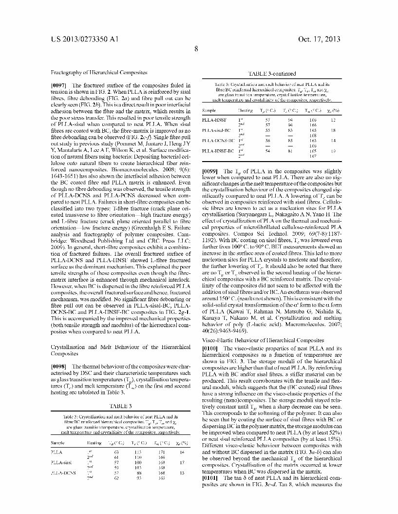
0098. The thermal behaviour of the composites were char acterised by DSC and their characteristic temperatures such as glass transition temperatures (T), crystallisation tempera tures (T,) and melt temperature (T) on the first and second heating are tabulated in Table 3.
TABLE 3
Table 3: Crystallisation and melt behavior of neat PLLA and its fibre/BC reinforced hierarchical composites. T.T.T., and X. are glass transition temperature, crystallisation temperature,
melt temperature and crystallinity of the composites, respectively.
Sample Heating T (C.) T. (C.) T (C.) X. (%) PLLA 1st 63 113 171 14
2nd 61 110 169 PLLA-sisal 1st 57 100 168 17
2nd 59 103 168 PLLA-DCNS 1st 57 88 168 13
2nd 62 93 169
Oct. 17, 2013
TABLE 3-continued
Table 3: Crystallisation and melt behavior of neat PLLA and its fibre/BC reinforced hierarchical composites. T.T.T., and X. are glass transition temperature, crystallisation temperature,
melt temperature and crystallinity of the composites, respectively.
Sample Heating T (C.) T. (C.) T., (C.) X. (%) PLLA-HNSF 1st 57 94 166 12
2nd 57 94 166 PLLA-sisal-BC 1 55 83 16S 18
2nd 168 PLLA-DCNS-BC 1 56 85 163 14
2nd 166 PLLA-HNSF-BC 1 S4 81 16S 19
2nd 167
(0099] The T of PLLA in the composites was slightly lower when compared to neat PLLA. There are also no sig nificant changes in the melt temperature of the composites but the crystallisation behaviour of the composites changed sig nificantly compared to neat PLLA. A lowering of T can be observed in composites reinforced with sisal fibres. Cellulo sic fibres are known to act as a nucleation sites for PLLA crystallisation (Suryanegara L., Nakagaito AN, Yano H. The effect of crystallization of PLA on the thermal and mechani cal properties of microfibrillated cellulose-reinforced PLA composites. Compos Sci Technol. 2009; 69(7-8): 1187 1192). With BC coating on sisal fibres, T was lowered even further from 100° C. to 90° C. BET measurements showed an increase in the surface area of coated fibres. This led to more nucleation sites for PLLA crystals to nucleate and therefore, the further lowering of T. It should also be noted that there are no T or T observed in the second heating of the hierar chical composites with a BC reinforced matrix. The crystal linity of the composites did not seem to be affected with the addition of sisal fibres and/or BC. An exotherm was observed around 150°C. (results not shown). This is consistent with the solid-solid crystal transformation of the O' form to the C. form of PLLA (Kawai T. Rahman N. Matsuba G, Nishida K. Kanaya T. Nakano M. et al. Crystallization and melting behavior of poly (L-lactic acid). Macromolecules. 2007: 40(26):9463-9469). Visco-Elastic Behaviour of Hierarchical Composites 0100. The visco-elastic properties of neat PLLA and its hierarchical composites as a function of temperature are shown in FIG. 3. The storage moduli of the hierarchical composites are higher than that of neat PLLA. By reinforcing PLLA with BC and/or sisal fibres, a stiffer material can be produced. This result corroborates with the tensile and flex ural moduli, which suggests that the (BC coated) sisal fibres have a strong influence on the Visco-elastic properties of the resulting (nano)composites. The storage moduli stayed rela tively constant until T when a sharp decrease can be seen. This corresponds to the softening of the polymer. It can also be seen that by coating the surface of sisal fibres with BC or dispersing BC in the polymer matrix, the storage modulus can be improved when compared to neat PLLA (by at least 52%) or neat sisal reinforced PLLA composites (by at least 15%). Different visco-elastic behaviour between composites with and without BC dispersed in the matrix (FIG. 3a-b) can also be observed beyond the mechanical T of the hierarchical composites. Crystallisation of the matrix occurred at lower temperatures when BC was dispersed in the matrix. 0101 The tan 8 of neat PLLA and its hierarchical com posites are shown in FIG. 3c-d. Tan 8, which measures the
US 2013/0273350 A1
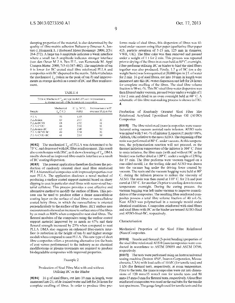
damping properties of the material, is also determined by the quality of fibre-matrix adhesion Baltazar-y-Jimenez A. Jun taro J. Bismarck A. J. Biobased Mater Bioenergy. 2008; 203): 264-272). A large tan 8 amplitude indicates a weak interface where a small tan 8 amplitude indicates stronger interface (van den Oever M J A, Bos H L. van Kemenade M. Appl Compos Mater. 2000; 7(5-6):387-402). The amplitude of tan Ö is lower for BC coated sisal fibre reinforced PLLA and composites with BC dispersed in the matrix. Table 4 tabulates the mechanical T (taken as the peak of tan Ö) and improve ments in storage moduli as a result of BC and fibre reinforce ment.
TABLE 4
Table 4: Mechanical T storage moduli (G') and improvements in storage moduli of the hierarchical composites.
Mechanical G' (a 30° C. Improvements in G' Sample T (C.) (GPa.) overneat PLLA (%)
PLLA 73 1.57 PLLA-sisal 69 2.07 32 PLLA-DCNS 68 2.52 61 PLLA-HNSF 66 2.52 61 PLLA-sisal-BC 63 2.49 59 PLLA-DCNS-BC 69 2.39 52 PLLA-HNSF-BC 61 2.64 69
10102) The mechanical T of PLLA was determined to be 73°C. and decreased with BC/fibre reinforcement. This result
also corroborates with DSC, as it shows lowering of T. DMA results showed an improved fibre-matrix interface as a result of BC coating/dispersion. 0103) The present application therefore discloses the pro duction of randomly oriented short sisal fibre reinforced PLLA hierarchical composites with improved properties over neat PLLA. The application discloses a novel method of producing a surface coated Support material based on slurry dipping to coat in particular sisal fibres with nano-sized bac terial cellulose. This process provides a cost effective and alternative method to modify the surface of fibres. This pro cess can be used to produce either a dense nanocellulose coating layer on the Surface of sisal fibres or nanocellulose coated hairy fibres, in which the nanocellulose is oriented perpendicularly to the surface of the fibres. BET surface area measurements showed an increase in Surface area of the fibres by as much as 800% when compared to neat sisal fibres. The flexural modulus of the composites using the Surface coated support material improved by as much as 67% and their flexural strength increased by 23% when compared to neat PLLA. DMA also suggests an enhanced fibre-matrix inter face (a reduction in the height of tan Ö) and higher storage moduli when compared to neat PLLA. This new type of short fibre composites offers a promising alternative (on the basis of cost versus performance) to the industry as no chemical modifications or plasma treatments are required to produce biodegradable composites with improved properties.
Example 2
Production of Sisal Fibre Mat with and without Utilising BC as the Binder
0104 16 g of sisal fibres, cut into 10 mm in length, were immersed into 2 L of de-ionised water and left for 24 hours for complete swelling of fibres. In order to produce fibre pre
Oct. 17, 2013
forms made of sisal fibres, this dispersion of fibres was fil tered under vacuum using filter paper (qualitative filter paper 413, particle retention of 5-13 lum, 125 mm in diameter, VWR, UK). The filter cake was then removed and pressed under a weight of 1 t for 2 min. This process was repeated prior to drying of the fibres in at oven held at 60°C. overnight. Fibre preforms utilising BC as binder to bind the sisal fibres together was also produced. Firstly, 1.7 g of BC (on a dry weight basis) was homogenised at 20,000 rpm in 2 L of water for 2 min. 16 g of sisal fibres, cut into 10 mm in length were immersed into this BC-water dispersion and left for 24 hours for complete swelling of the fibres. The sisal fibre volume fraction is 90 wt.-%. This BC-sisal fibre-water dispersion was then filtered under vacuum, pressed twice under a weight of 1 t for 2 min and dried in an oven overnight held at 60° C. A schematic of this fibre mat-making process is shown in FIG. 4.
Production of Randomly Oriented Sisal Fibre Mat Reinforced Acrylated Epoxidised Soybean Oil (AESO) Composites
0105. The fibre reinforced (nano)composites were manu factured using vacuum assisted resin infusion. AESO resin was mixed with 5 wt.-% of initiator (Luperox P. purity-98%, Aldrich, UK) relative to the mass AESO. The degassing of the resin was performed at 80°C. under vacuum. At this tempera ture, the polymerisation reaction will not proceed, as the thermal initiation temperature of the initiator is 104°C. Prior to resin infusion, the fibre mats (with and without BC as the binder) was further dried at 120° C. under a weight of 250 kg for 15 min. The fibre preforms were vacuum bagged on a one-sided mould, i.e. the tooling side and AESO was drawn into the vacuum bag under the driving force created by vacuum. The resin and the vacuum bagging were held at 80° C. during the infusion process to reduce the viscosity of AESO. The resin was then cured at 110° C. for 2 hand post cured at 130°C. for another 2 hprior to cooling down to room temperature overnight. During the curing process, the vacuum bagging was left under vacuum to improve consoli dation of the composites. The resulting fibre reinforced com posites possess a total fibre volume fraction of 40 vol.-%. Neat AESO was polymerised in a rectangle mould under identical conditions. Composites reinforced with sisal fibres and sisal fibres with BC as the binder are termed AESO-Sisal and AESO-Sisal-BC, respectively.
Characterisation
Mechanical Properties of the Sisal Fibre Reinforced (Nano)Composites
0106 Tensile and flexural (3-point bending) properties of the sisal fibre reinforced AES 0 (nano)composites were con ducted in accordance to ASTM D3039 and ASTM D790, respectively. 0107 The tests were performed using an Instron universal testing machine (Instron 4505. Instron Corporation, Massa chusetts, USA) with load cells of 10 kN (for tensile test) and 1 kN (for flexural test), respectively, at room temperature. Prior to the tests, the (nano)composites were cut into dimen sions of 120 mmx15 mmx3 mm for tensile tests and 80 mmx15 mmx3 mm for flexural tests, respectively. Glass fibre reinforced composites was used as the end tabs for the tensile test specimens. The gauge length used for tensile tests and the
US 2013/0273350 A1
span for flexural test were both 60 mm. The testing speed used was 1 mm min' for all tests. Strain gauges (FLA-2-11, Techni Measure, Warwickshire, UK) were used in tensile tests to provide accurate description of the sample strain. A total of 5 samples were tested for each specimen.
Dynamic Mechanical Analysis (DMA) of the Sisal Fibre Reinforced (Nano)Composites 0108. The visco-elastic behaviour of the (nano)compos
ites was investigated using DMA (Tritec 2000, Triton Tech nology Ltd, Keyworth, UK). DMA was performed in single beam cantilever bending mode with a gauge length of 10 mm. The sample has a thickness and width of approximately 3 mm. The storage modulus, loss modulus and energy dissipa tion factor (tan 8) were measured from -100° C. to 180° C. at a heating rate of 5° C. min' and a frequency of 1 Hz. Results and Discussion
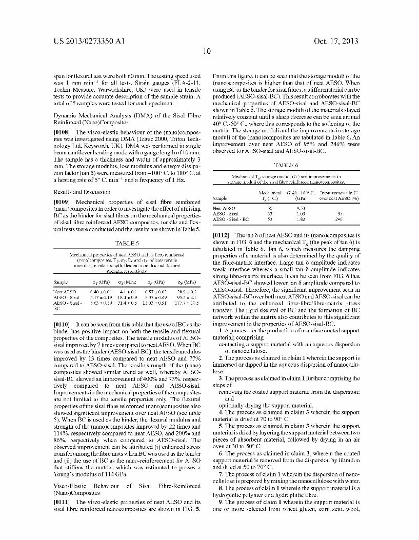
0109 Mechanical properties of sisal fibre reinforced (nano)composites. In order to investigate the effect of utilising BC as the binder for sisal fibres on the mechanical properties of sisal fibre reinforced AESO composites, tensile and flex ural tests were conducted and the results are shown in Table 5.
TABLE 5
Mechanical properties of neat AESO and its fibre reinforced (nano)composites. E. O. E. and of indicate tensile
modulus, tensile strength, flexural modulus and flexural strength, respectively.
Sample E (GPa.) or (MPa) E. (GPa.) or (MPa)
Neat AESO O.40 OO1 41 01 0.57 O.O3 28.9 O.2 AESO - Sisal 3.17 O.19 18.4 O.9 6.07 - 0.49 95.3 - 4.1 AESO - Sisal - 5.63 - 0.39 31.4 - 0.5 13.03 - 0.91 177.7 10.5 BC
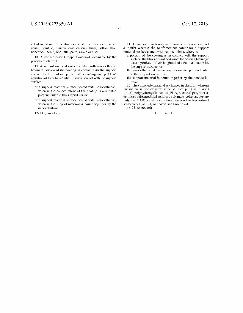
0110. It can be seen from this table that the use of BC as the binder has positive impact on both the tensile and flexural properties of the composites. The tensile modulus of AESO sisal improved by 7 times compared to neat AESO. When BC was used as the binder (AESO-sisal-BC), the tensile modulus improved by 13 times compared to neat AESO and 77% compared to AESO-sisal. The tensile strength of the (nano) composites showed similar trend as well, whereby AESO sisal-BC showed an improvement of 400% and 73%, respec tively compared to neat AESO and AESO-sisal. Improvements in the mechanical properties of the composites are not limited to the tensile properties only. The flexural properties of the sisal fibre reinforced (nano)composites also showed significant improvement over neat AESO (see table 5). When BC is used as the binder, the flexural modulus and strength of the (nano)composites improved by 22 times and 114%, respectively compared to neat AESO, and 200% and 86%, respectively when compared to AESO-sisal. The observed improvement can be attributed (i) enhanced stress transfer among the fibre mats when BC was used as the binder and (ii) the use of BC as the nano-reinforcement for AESO that stiffens the matrix, which was estimated to posses a Young's modulus of 114 GPa. Visco-Elastic Behaviour of Sisal Fibre-Reinforced (Nano)Composites 0111. The visco-elastic properties of neat AESO and its sisal fibre reinforced nanocomposites are shown in FIG. 5.
Oct. 17, 2013
From this figure, it can be seen that the storage moduli of the (nano)composites is higher than that of neat AESO. When using BC as the binder for sisal fibres, a stiffer material can be produced (AESO-sisal-BC). This result corroborates with the mechanical properties of AESO-sisal and AESO-sisal-BC shown in Table 5. The storage moduli of the materials stayed relatively constant until a sharp decrease can be seen around 40° C.-50° C., where this corresponds to the softening of the matrix. The storage moduli and the improvements in storage moduli of the (nano)composites are tabulated in Table 6. An improvement over neat AESO of 95% and 24.6% were observed for AESO-sisal and AESO-sisal-BC.
TABLE 6
Mechanical T storage moduli (G') and improvements in storage moduli of the sisal fibre reinforced (nano)composites.
Mechanical G" (a) -100° C. Improvements in G' Sample T (C.) (GPa.) overneat AESO (%)
Neat AESO 50 O.S3 AESO - Sisal 53 1.03 95 AESO - Sisal - BC 53 1.82 246
0112 The tan 8 of neat AESO and its (nano)composites is shown in FIG. 6 and the mechanical T (the peak of tan 8) is tabulated in Table 6. Tan 6, which measures the damping properties of a material is also determined by the quality of the fibre-matrix interface. Large tan 8 amplitude indicates weak interface whereas a small tan 6 amplitude indicates strong fibre-matrix interface. It can be seen from FIG. 6 that AESO-sisal-BC showed lower tan 8 amplitude compared to AESO-sisal. Therefore, the significant improvement seen in AESO-sisal-BC over both neat AESO and AESO-sisal can be attributed to the enhanced fibre-fibre/fibre-matrix stress transfer. The rigid skeletal of BC and the formation of BC network within the matrix also contributes to this significant improvement in the properties of AESO-sisal-BC.
1. A process for the production of a Surface coated Support material; comprising
contacting a Support material with an aqueous dispersion of nanocellulose.
2. The process as claimed in claim 1 wherein the Support is immersed or dipped in the aqueous dispersion of nanocellu lose.
3. The process as claimed in claim 1 further comprising the steps of
removing the coated Support material from the dispersion; and
optionally drying the Support material. 4. The process as claimed in claim 3 wherein the Support
material is dried at 70 to 90° C. 5. The process as claimed in claim 3 wherein the support
material is dried by layering the support material between two pieces of absorbent material, followed by drying in an air Oven at 30 to 50° C.
6. The process as claimed in claim 3, wherein the coated support material is removed from the dispersion by filtration and dried at 50 to 70° C.
7. The process of claim 1 wherein the dispersion of nano cellulose is prepared by mixing the nanocellulose with water.
8. The process of claim 1 wherein the support material is a hydrophilic polymer or a hydrophilic fibre.
9. The process of claim 1 wherein the support material is one or more selected from wheat gluten, corn Zein, wool,
US 2013/0273350 A1
cellulose, starch or a fibre extracted from one or more of abaca, bamboo, banana, coir, coconut husk, cotton, flax, henequen, hemp, hop, jute, palm, ramie or sisal.
10. A surface coated support material obtainable by the process of claim 1.
11. A Support material Surface coated with nanocellulose having a portion of the coating in contact with the Support Surface, the fibres of said portion of the coating having at least a portion of their longitudinal axis in contact with the Support Surface
or a Support material Surface coated with nanocellulose, wherein the nanocellulose of the coating is orientated perpendicular to the Support Surface
or a Support material Surface coated with nanocellulose, wherein the support material is bound together by the nanocellulose.
12-13. (canceled)
Oct. 17, 2013
14. A composite material comprising a reinforcement and a matrix wherein the reinforcement comprises a Support material Surface coated with nanocellulose, wherein:
a portion of the coating is in contact with the Support Surface, the fibres of said portion of the coating having at least a portion of their longitudinal axis in contact with the Support Surface; or
the nanocellulose of the coating is orientated perpendicular to the Support Surface; or
the Support material is bound together by the nanocellu lose.
15. The composite material as claimed in claim 14 wherein the matrix is one or more selected from poly(lactic acid) (PLA), polyhydroxyalkanoates (PHA, bacterial polyesters), cellulose pulp, modified cellulose polymers (cellulose acetate butyrate (CAB) or cellulose butyrate) or acrylated epoxidised soybean oil (AESO) or epoxidised linseed oil.
16-22. (canceled)