18SP718 - EPA07 DD15/16 Three-Filter ESOC Fuel System to ...If equipped with a Motor Control Module...
15
18SP718 - EPA07 DD15/16 Three-Filter ESOC Fuel System to Two-Filter KM59 GEN1 Fuel System Conversion Service Kit (P/N: A4710901355) KIT DESCRIPTION This service kit includes all necessary parts to convert the D015/16 three-filter fuel system to the D015/16 two-filter KM59 GEN1 fuel system. KIT CONTENTS Part No. Qty. Description A4710909952 1 Fuel Filter module (ESOC) A4722030315 1 Connecting pipe A4722003852 1 Coolant line A4722030640 1 Radiator Support Bracket A4730702532 1 Needle Return Line A4730702432 1 Amplifier Return Line A4730702332 1 Pressure Limiting Valve Return Line A0060705401 1 Low Pressure Fuel Lines A4730702732 1 High Pressure Pump Inlet Line A4730702932 1 HiQh Pressure Pump Outlet Line A4710700635 1 Doser Fuel Supply Line A4710780844 1 High Pressure Flange A0000700932 1 High Pressure Fuel Line Kit A4730700440 1 Return Line P-clip A4700780335 2 Rail Clamps A4700780735 1 Rear Rail Clamp A0045405305 1 Water-In-Fuel Wiring Harness A0045405205 1 Fuel Temperature Wiring Harness A4720781144 1 LPPO PluQ 05101020 2 Zip Tie N916016015206 2 Coolant Line Clamp A4700780231 1 Cylinder Head Fitting A4720780531 1 Cylinder Head Fitting N910105010021 6 M8x55 Bolt N910105010007 1 M8x36 Bolt N910105008005 11 M8x25 Bolt N910105008011 2 M8x20 Bolt N910105008008 1 M8x16 Bolt 18SP718 Page 1 of 15
Transcript of 18SP718 - EPA07 DD15/16 Three-Filter ESOC Fuel System to ...If equipped with a Motor Control Module...

18SP718 - EPA07 DD15/16 Three-Filter ESOC Fuel System to Two-Filter KM59 GEN1 Fuel System Conversion Service Kit (P/N: A4710901355)
KIT DESCRIPTION This service kit includes all necessary parts to convert the D015/16 three-filter fuel system to the D015/16 two-filter KM59 GEN1 fuel system.
KIT CONTENTS
Part No. Qty. Description A4710909952 1 Fuel Filter module (ESOC) A4722030315 1 Connecting pipe A4722003852 1 Coolant line A4722030640 1 Radiator Support Bracket A4730702532 1 Needle Return Line A4730702432 1 Amplifier Return Line A4730702332 1 Pressure Limiting Valve Return Line A0060705401 1 Low Pressure Fuel Lines A4730702732 1 High Pressure Pump Inlet Line A4730702932 1 HiQh Pressure Pump Outlet Line A4710700635 1 Doser Fuel Supply Line A4710780844 1 High Pressure Flange A0000700932 1 High Pressure Fuel Line Kit A4730700440 1 Return Line P-clip A4700780335 2 Rail Clamps A4700780735 1 Rear Rail Clamp A0045405305 1 Water-In-Fuel Wiring Harness A0045405205 1 Fuel Temperature Wiring Harness A4720781144 1 LPPO PluQ
05101020 2 Zip Tie N916016015206 2 Coolant Line Clamp A4700780231 1 Cylinder Head Fitting A4720780531 1 Cylinder Head Fitting
N910105010021 6 M8x55 Bolt N910105010007 1 M8x36 Bolt N910105008005 11 M8x25 Bolt N910105008011 2 M8x20 Bolt N910105008008 1 M8x16 Bolt
18SP718 Page 1 of 15
A0019901207 6 M6x28 Micro-encapsulated Bolt 18SP718 1 Installation Instructions
Removal of the Three-Filter Fuel System
Remove as follows:
1. Shut off the engine, apply the parking brake, chock the wheels, and perform any other applicable safety steps.
2. Disconnect the batteries. 3. Steam clean the engine.
£WARNING:
FIRE HAZARD Do not power wash or steam clean the engine bay in the area of vehicle electrical components, unless specified by vehicle manuals or service literature. Power washing/steam cleaning can permanently damage these components, which could result in fire, personal injury, or property damage.
4. Remove the fuel feed line from the fuel filter module. 5. Using W470589039100, install J-48710 fuel pressure test kit onto the fuel feed
line at the fuel filter module. 6. Remove the fuel tank fill caps. 7. Using regulator, adjust the system pressure to 345 kPa (50 psi). 8. Pressurize the fuel system for two minutes. 9. Remove J-48710 fuel pressure test kit from the fuel filter module. 10. Install the fuel tank fill caps. 11. Remove the chassis return line from the fuel filter module. 12. Remove the coolant reservoir cap. 13. Open the coolant drain plug (1) located on the left side of the engine block and
attach a hose to the plug.
18SP718 Page 2 of 15

NOTICE: Coolant is a hazardous material and needs to be disposed in an environmentally responsible manner.
1
d090094
14. Collect the used coolant in a suitable container and if necessary, dispose of the solution in an environmentally responsible manner according to state and federal Environmental Protection Agency (EPA) recommendations.
1
15. Close the drain plug. Torque to 30 N·m (22 lb·ft).
18SP718 Page 3 of 15
16. Disconnect the coolant lines from the front and bottom of the fuel filter module. 17. Remove the P-clip bolt holding the coolant line to the oil/coolant module. 18. Disconnect the coolant line from the oil/coolant module and remove the coolant
line from the engine. Discard coolant line. 19. Disconnect the water-in-fuel and fuel temperature electrical connectors.
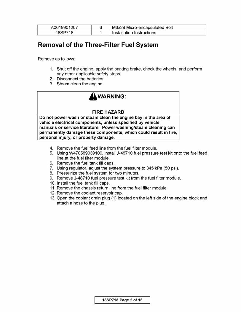
NOTE: The Motor Control Module (MCM) fuel cooler is no longer used on the two-filter KM59 GEN1 fuel system. No modification to the MCM is necessary.
20. If equipped with a Motor Control Module (MCM) fuel cooler, remove and discard both MCM fuel cooler lines (1) from the fuel filter module.
d470155
21. If equipped, remove and discard the emergency lubrication line from the fuel filter module and the high pressure flange.
22. Remove the high pressure pump inlet line from the fuel filter module and the high pressure flange. Discard the high pressure pump inlet line.
23. Remove the high pressure pump outlet line from the fuel filter module and the high pressure flange. Discard the high pressure pump outlet line.
24. On VS three-filter fuel systems only, remove the banjo bolt and both sealing washers from the low pressure fuel pump inlet line. Discard the banjo bolt and sealing washers.
25. On VS three-filter fuel system only, remove and discard the P-clip bolt securing the amplifier line to the fuel filter module.
26. Remove the low pressure fuel pump inlet line from the fuel filter module and the low pressure flange. Discard the low pressure fuel pump inlet line.
27. Remove the low pressure fuel pump outlet line from the fuel filter module and the low pressure flange. Discard the low pressure fuel pump outlet line.
18SP718 Page 4 of 15

28. Remove the needle, amplifier, and pressure limiting valve return lines and needle return pressure control valve from the fuel filter module.
29. Disconnect the engine wiring harness clip from the fuel filter module. 30. Remove the four bolts securing the fuel filter module to the cylinder block.
Discard the four bolts. 31. Remove fuel filter module from the engine. Discard the fuel filter module. 32. Remove the fuel cooler rubber coupling from the engine block. Discard the fuel
cooler rubber coupling. 33. Remove the radiator support rod from the radiator support bracket. Position
aside radiator support rod. 34. Remove the radiator support bracket. Discard the radiator support bracket. 35. Disconnect the coolant line from the air compressor and remove the coolant
line from the engine. Discard the coolant line. 36. Remove and discard the low pressure flange and gasket from the high
pressure fuel pump. 37. Remove the doser fuel supply line from the doser block. Discard the doser fuel
supply line. 38. Remove the needle return line from the high pressure flange. 39. Unclip the engine wiring harness from the high pressure flange. 40. Remove and discard the high pressure flange and gasket from the high
pressure fuel pump. 41. Remove and discard the return lines P-clip bolt from the mounting bracket (1 ).
a. The graphic below illustrates the DD15/16 engines with a serial number before 472901S0012796.
4
6
d470116
18SP718 Page 5 of 15
NOTE:
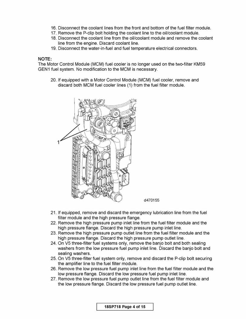
b. The graphic below illustrates the DD15/16 engines with a serial number after 472901S0012796 and all DD13 engines.
4
d470099
42. Remove and discard the two bolts and P-clips (6) from the mounting bracket (1).
43. Cover the high pressure fuel pump elements and high pressure fuel rail feed line sealing areas on the fuel rail with a clean shop towel.
44. Remove and discard the mounting bracket bolts (2) from the intake manifold and the mounting bracket (1).
When using tool J-48770 to remove the high pressure pump rail feed lines, hold the high pressure pump fitting with a 24mm wrench.
45. Using tool J-48770, remove the high pressure pump rail feed lines (5) and vibration dampers (4) from the fuel rail and high pressure fuel pump. Discard the high pressure pump rail feed lines and vibration dampers.
46. Remove and discard the return lines P-clip (3). 47. Holding the rear needle cylinder head fitting with J-48836, use J-48770 to
remove the needle return line from the rear cylinder head fitting and remove the needle return line. Discard the needle return line.
48. Holding the rear amplifier cylinder head fitting with J-48836, use J-48770 to remove the amplifier return line from the rear amplifier cylinder head fitting and remove the amplifier return line. Discard the amplifier return line.
49. Remove and discard the needle and amplifier cylinder head fittings and sealing washers from the cylinder head.
50. Remove and discard the Pressure Limiting Valve (PLV) line from the fuel rail. 51. Remove and discard all six rail clamp bolts and three rail clamps from
the engine.
18SP718 Page 6 of 15
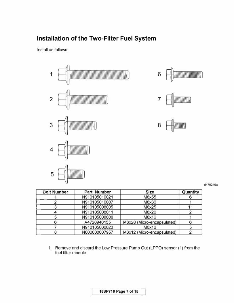
Installation of the Two-Filter Fuel System
Install as follows:
1 ~, ...... ~ 2 ~,IWl@l@B~
3 ~ ,~ll@Wml~
4
5 ~
Bolt Number Part Number 1 N910105010021 2 N910105010007 3 N910105008005 4 N910105008011 5 N910105008008
Size M8x55 M8x36 M8x25 M8x20 M8x16
7 EijaaJ
8 ~
Quantity 6 1
11 2 1
6 A4720940155 M6x28 (Micro-encapsulated) 6 7 N910105006023 M6x16 5 8 N000000007957 M6x12 (Micro-encapsulated) 2
1. Remove and discard the Low Pressure Pump Out (LPPO) sensor (1) from the fuel filter module.
18SP718 Page 7 of 15
d470249a
1
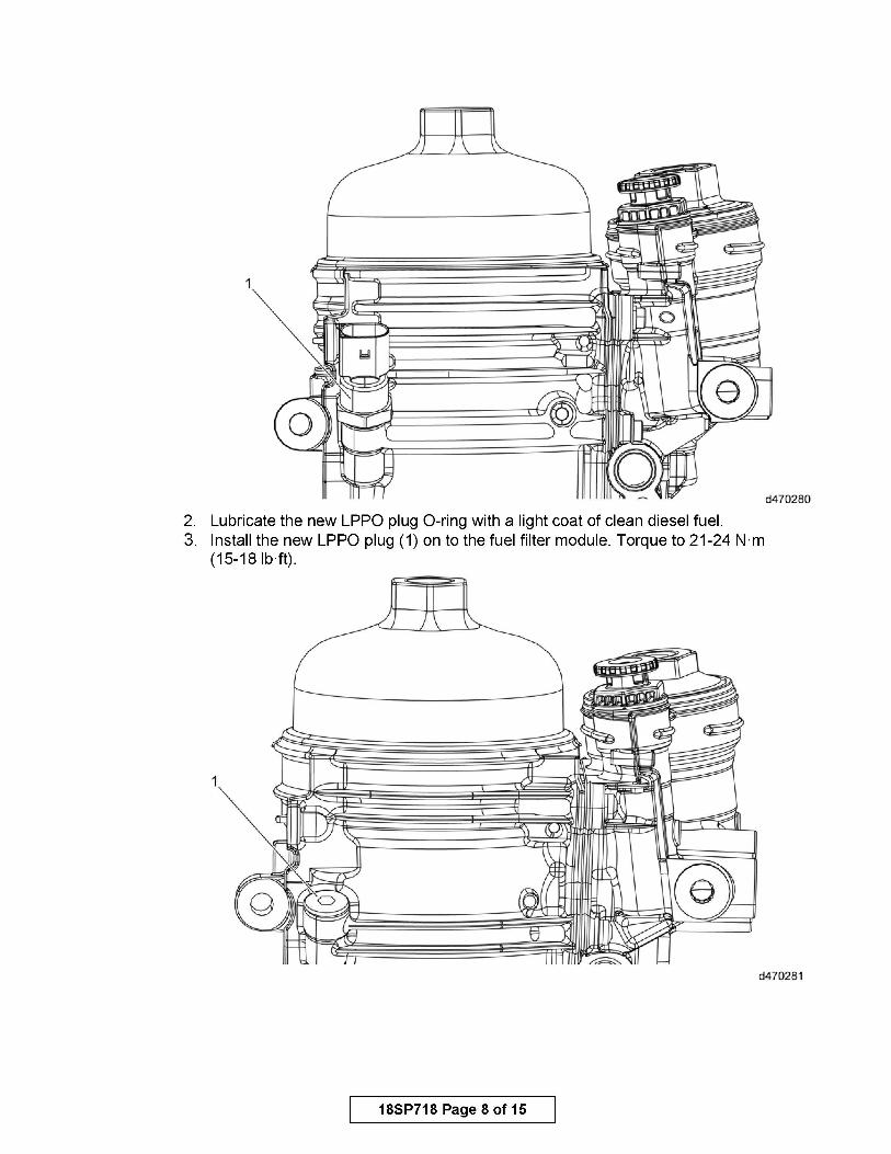
2. Lubricate the new LPPO plug O-ring with a light coat of clean diesel fuel. 3. Install the new LPPO plug (1) on to the fuel filter module. Torque to 21-24 N·m
(15-18 lb·ft).
d470281
18SP718 Page 8 of 15

NOTE: The rear fuel rail clamp has mounting holes for the high pressure fuel lines mounting bracket.
4. With the arrows pointing upwards, install the three new fuel rail clamps and six new fuel rail clamp bolts (M6x28 microencapsulated bolt number 6). Torque to 14 N·m (120 lb·in.).
5. Install the new PLV return line, new sealing washers and new PLV banjo bolt. Hand-tighten the PLV banjo bolt. Do not torque at this time.
6. Using new sealing washers, install the new needle and amplifier cylinder head fittings on to the cylinder head. Torque to 55-60 N·m (40-44 lb·ft).
7. Install the new needle and amplifier return lines on to the cylinder head fittings. Hand-tighten the lines. Do not torque at this time.
NOTICE: DO NOT install any high pressure fuel line bolts and fittings using power tools. All bolts and fittings MUST be installed using hand tools.
AwARNING:
PERSONAL INJURY All parts provided within this kit must be installed in the proper locations, and MUST be fastened to the specified torque. Failure to properly torque hardware/components will result in failure of a high pressure fuel feed line, resulting in possible fire and/or personal injury.
18SP718 Page 9 of 15
d470160c
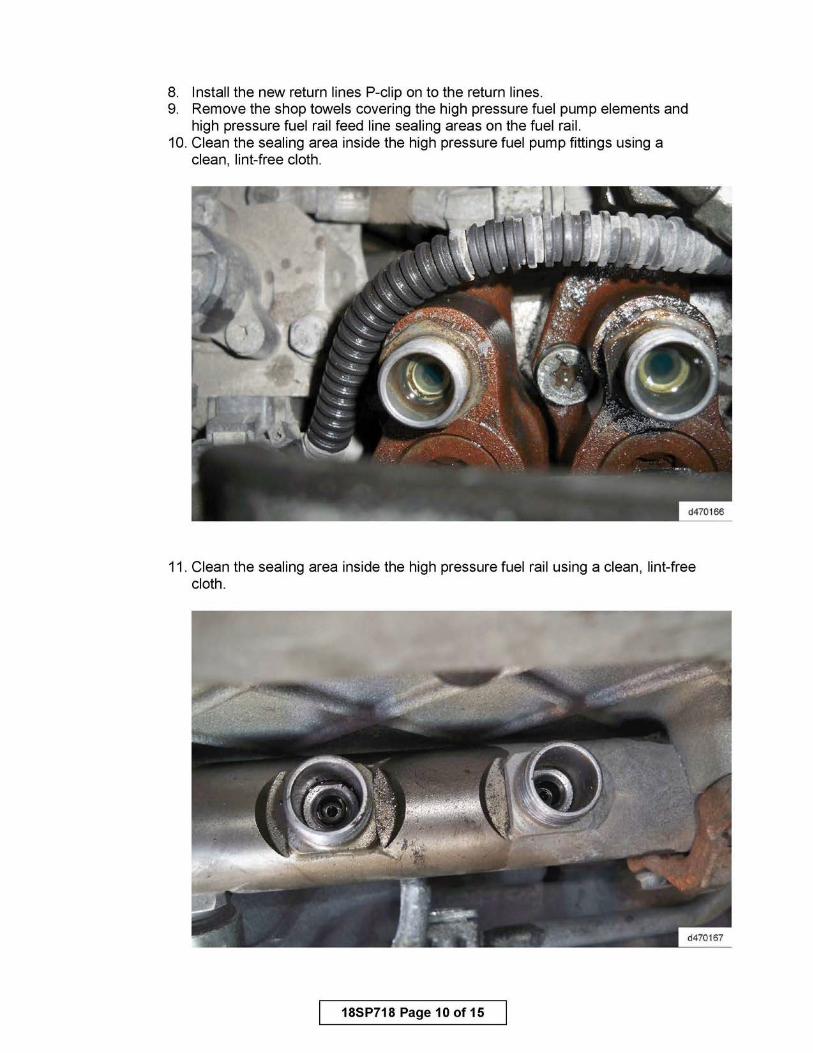
8. Install the new return lines P-clip on to the return lines. 9. Remove the shop towels covering the high pressure fuel pump elements and
high pressure fuel rail feed line sealing areas on the fuel rail. 10. Clean the sealing area inside the high pressure fuel pump fittings using a
clean, lint-free cloth.
11. Clean the sealing area inside the high pressure fuel rail using a clean, lint-free cloth.
18SP718 Page 10 of 15

NOTE:
12. Install the rear high pressure fuel line (3) to the fuel rail and the high pressure fuel pump. Hand-tighten the nuts.
13. Using tool J-48770, torque the rear high pressure fuel line nuts to 40 N·m (30 lb·ft).
14. Install the front high pressure fuel line (3) to the fuel rail and the high pressure fuel pump. Hand-tighten the nuts.
15. Using tool J-48770, torque the front high pressure fuel line nuts to 40 N·m (30 lb·ft).
16. Install the new mounting bracket (2) and two new mounting bracket bolts (4) (M6x16 bolt number 7) to the fuel rail clamp. Torque to 15 N·m (132 lb·in.).
17. Install the two new P-clips (5) and two new bolts (M6x12 microencapsulated bolt number 8) to the high pressure fuel rail feed lines (3) and the mounting bracket (2). Torque to 15 N·m (132 lb·in.).
18. Install a new bolt (1) (M6x16 bolt number 7) on to the return lines P-clip. Torque to 15 N·m (132 lb·in.).
DO NOT use high pressure fuel lines without new vibration dampers and new bolts installed.
NOTE:
19. Using J-48770, torque the needle and amplifier return lines on to the cylinder head fittings at the rear of the cylinder head to 25 N·m (18 lb·ft).
20. Torque the PLV line to the fuel rail to 30-33 N·m (22-24 lb·ft). 21. Clean the high pressure flange mating surface on the high pressure
fuel pump. 22. Install the new high pressure fuel flange onto the high pressure fuel pump
using M8x25 bolt number 3. Torque to 30 N·m (22 lb·ft). 23. Clip the engine wiring harness on to the high pressure flange. 24. Install the new doser fuel supply line with new sealing washers on to the high
pressure fuel flange and doser block. Torque to 25 N·m (18 lb·ft). 25. Lightly lubricate the new fuel cooler rubber coupling with clean engine coolant
and install the new rubber coupling into the cylinder block. 26. Install the new radiator support bracket on to the engine using M8x55 bolt
number 1 and M8x36 bolt number 2. Torque to 60 N·m (44 lb·ft). 27. Position back radiator support rod and install the radiator support rod on to the
radiator support bracket. Torque to OEM specification.
The new radiator support bracket no longer has a mounting point for the fuel filter module; this will not affect the stability of the fuel filter module.
18SP718 Page 11 of 15

28. Install the new fuel filter module to the cylinder block with the four new mounting bolts (M8x55 bolt number 1). Torque to 60 N·m (44 lb·ft).
29. Install and connect the new coolant line on to the air compressor, fuel filter and oil/coolant filter module.
30. Install the new P-clips on to the coolant line.
d130044
18SP718 Page 12 of 15

31. Install the mounting bolts (M8x20 bolt number 4) securing coolant line clips to the fuel filter module and oil/coolant filter module. Torque to 30 N·m (22 lb·ft).
32. Using new sealing washers, install the needle, amplifier, and pressure limiting valve return lines on to the fuel filter module. Torque to 30-33 N·m (22-24 lb·ft).
33. Lubricate the new high pressure pump inlet/outlet lines and the low pressure fuel pump inlet/outlet lines O-rings with a light coat of clean diesel fuel.
34. Install the new low pressure fuel pump inlet and outlet lines on to the fuel filter module and the high pressure fuel pump using M8x25 bolt number 3. Torque to 30 N·m (22 lb·ft).
35. Install the new wiring harness bracket on to the fuel filter module using M8x25 bolt number 3 and low pressure lines using M8x16 bolt number 5. Torque to 30 N·m (22 lb·ft).
36. Install the new high pressure pump inlet and outlet lines on to the fuel filter module and the high pressure flange using M8x25 bolt number 3. Torque to 30 N·m (22 lb·ft).
NOTICE: Wiring harnesses must NOT come into contact with ANY coolant lines or fuel lines.
37. Install and connect the new water-in-fuel and fuel temperature wiring harnesses.
38. Using a zip tie (1), attach the water-in-fuel wiring harness to the wiring harness bracket.
39. Using a zip tie (1), attach the fuel temperature wiring harness to the low pressure flange.
18SP718 Page 13 of 15
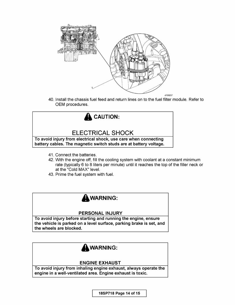
40. Install the chassis fuel feed and return lines on to the fuel filter module. Refer to OEM procedures.
AcAur10N:
ELECTRICAL SHOCK To avoid injury from electrical shock, use care when connecting battery cables. The magnetic switch studs are at battery voltage.
41. Connect the batteries. 42. With the engine off, fill the cooling system with coolant at a constant minimum
rate (typically 6 to 8 liters per minute) until it reaches the top of the filler neck or at the "Cold MAX" level.
43. Prime the fuel system with fuel.
AwARNING:
PERSONAL INJURY To avoid injury before starting and running the engine, ensure the vehicle is parked on a level surface, parking brake is set, and the wheels are blocked.
AwARNING:
ENGINE EXHAUST To avoid injury from inhaling engine exhaust, always operate the engine in a well-ventilated area. Engine exhaust is toxic.
18SP718 Page 14 of 15

44. Start the engine (no coolant reservoir cap) and idle for one minute. Increase engine speed slowly to 1000-1200 RPM and hold for one minute. Then reduce engine speed to idle and cycle up and down between idle and 1000-1200 rpm for one additional minute.
45. After this three minute burp sequence, stop the engine and add coolant as required to achieve "Cold FULL" level. If a second top-off is needed, start the engine and idle the engine for one additional minute.
46. Stop the engine and add coolant as required to achieve the "Cold MAX" level, and then install the coolant reservoir cap.
AwARNING:
PERSONAL INJURY To avoid injury before starting and running the engine, ensure the vehicle is parked on a level surface, parking brake is set, and the wheels are blocked.
AwARNING:
ENGINE EXHAUST To avoid injury from inhaling engine exhaust, always operate the engine in a well-ventilated area. Engine exhaust is toxic.
NOTE: This will eliminate the large pockets of air from the system, although smaller bubbles will still remain. Normal operation of the vehicle should purge the remaining air bubbles from the system without any damage. Extremely large cooling systems (such as in motor homes or luxury coaches) may require additional time for system deaeration.
47. Start the engine and inspect for leaks.
13400 Outer Drive, West, Detroit, Michigan 48239-4001 Tele phone: 313-592-50 00 WWW.DEMANDDETROIT.COM
Specifications are subject to change without notice. Detroit Diesel Corporation is registered to ISO 9001 :2008. Copyright© Detroit Diesel Corporation. All rights reserved. Detroit™ is a brand of Detroit Diesel Corporation, a Daimler company. 18SP718 1511 As technical advances continue, specifications will change. Printed in U.S.A
18SP718 Page 15 of 15


![metabolic fuel preference in skeletal muscle€¦ · ifen-inducible Cre recombinase (MerCreMer [MCM]) under the control of the skeletal muscle α-actin pro-moter (Ska-MCM; Figure](https://static.fdocuments.in/doc/165x107/5ead916bf86d8c108c1218e5/metabolic-fuel-preference-in-skeletal-muscle-ifen-inducible-cre-recombinase-mercremer.jpg)