185 CFM Towable Compressor Operator’s...
48
Not for Reproduction Copyright © 2016 Allmand Bros., Inc. Holdrege, NE, USA. All rights reserved. 111075USCN Rev (A) 185 CFM Towable Compressor Operator’s Manual
-
Upload
truongcong -
Category
Documents
-
view
218 -
download
1
Transcript of 185 CFM Towable Compressor Operator’s...
Not for
Reprod
uctio
n
Copyright © 2016 Allmand Bros., Inc.Holdrege, NE, USA. All rights reserved.
111075USCN Rev (A)
185 CFM Towable CompressorOperator’s Manual
Not for
Reprod
uctio
n
2 ALLMAND.COM
Thank you for purchasing this quality-built Allmand towable compressor. We are pleased that you’ve placed your confidence in the Allmand brand. When operated and maintained according to the instructions in this manual, your Allmand compressor will provide many years of dependable service.
This manual contains safety information to make you aware of the hazards and risks associated with towable compressors and how to avoid them. Because Allmand does not necessarily know all the applications this towable compressor could be used for, it is important that you read and understand these instructions thoroughly before attempting to start or operate this equipment. Save these original instructions for future reference.
Where to Find Us
If you have any questions about the machine, contact your authorized dealer. You can also contact Allmand Customer Service by phone at (800) 562-1373, or on the Internet at allmand.com.
Knowing the model number of your Allmand Air Compressor will make it easy to order maintenance or repair parts either online or from your local dealer. The model number is generally a number stamped into metal or on a sticker directly on your product.
Towable Compressor Engine
Model Number _____________________ Model Number ______________________
Revision __________________________ Type Number _______________________
Serial Number ______________________ Code Number _______________________
Date Purchased ___________________

Not for
Reprod
uctio
n
3
Table of ContentsOperator Safety. . . . . . . . . . . . . . . . . . . . . . . 4Features and Controls . . . . . . . . . . . . . . . . . 9Transporting and Set-Up . . . . . . . . . . . . . . 12Operation. . . . . . . . . . . . . . . . . . . . . . . . . . . 13Maintenance . . . . . . . . . . . . . . . . . . . . . . . . 23Storage . . . . . . . . . . . . . . . . . . . . . . . . . . . . 31Troubleshooting . . . . . . . . . . . . . . . . . . . . . 32Specifications . . . . . . . . . . . . . . . . . . . . . . . 36Wiring Diagram . . . . . . . . . . . . . . . . . . . . . . 39Piping Diagram . . . . . . . . . . . . . . . . . . . . . . 40Operation Log . . . . . . . . . . . . . . . . . . . . . . . 42Noise Emission . . . . . . . . . . . . . . . . . . . . . . 44

Not for
Reprod
uctio
n
4 ALLMAND.COM
Operator SafetyEquipment Description
Read this manual carefully and become familiar with your towable compressor. Know its applications, its limitations, and any hazards involved.
Every effort has been made to ensure that information in this manual is accurate and current. Figures and drawings in this manual may differ slightly from your model. However, we reserve the right to change, alter, or otherwise improve the product and this document at any time without prior notice.Safety and Control SymbolsThe safety alert symbol indicates a potential personal injury hazard. A safety symbol may be used to represent the type of hazard. DANGER indicates a hazard which, if not avoided, will result in death or serious injury. WARNING indicates a hazard which, if not avoided, could result in death or serious injury. CAUTION indicates a hazard which, if not avoided, could result in minor or moderate injury. NOTICE indicates information considered important, but not hazard-related.
WARNING Read and follow safety directions:• Be sure safety decals are present and legible.
Replace if damaged or missing.• Do not modify machine without prior approval.
Machine safety may be compromised, functions may be altered, or machine life may be shortened.
• Never use machine for purpose of compression of gases other than air, or as a vacuum pump. Death or serious injury could result.
DANGER! Compressed air is not to be used for human respiration.• Compressed air from this machine contains
poisonous materials. Never use compressed air for human respiration. Breathing compressed air could result in death or serious injury.
• This machine is not designed to provide air for working inside wells or tunnels. Doing so could result in death or serious injury.
WARNING VENTILATION!• Exhaust gas from the engine is poisonous, and could
cause death when inhaled.• Avoid using the machine in an insufficiently
ventilated building or tunnel. WARNING
• Keep flames away from battery.• Battery may generate hydrogen gas, which is
explosive.• Battery electrolyte is dilute sulfuric acid. Mishandling
could result in severe burns.• When handling battery, be sure to wear appropriate
safety protection such as safety goggles and gloves.• Dispose of battery according to local, state and/or
federal regulations. WARNING Hose attachment and removal
precautions:• Piping or hose connected to compressor service
valve must meet or exceed rated discharge pressure. Failure to observe and comply could result in death or serious injury.
• Connect piping or hose to machine service valve securely before operation. Failure to do so could result in death or serious injury.
• Removing piping or hose prior to closing service valve or discharging pressure could result in death or serious injury. Stop machine, close service valve, and discharge remaining pressure before removing piping or hose.
• Use proper tools when connecting or disconnecting piping or hose.
Fire
ExplosionToxic Fumes
Hot Surface
Rotating Parts
Organic Waste
Protective Gear
Explosive Pressure
Operator’s Manual
Battery
Clothing Prohibited
Amputation Hazard
Alert
SafetyFittings
Hand Injury
Propelling Parts
LightingApparatus
Not for
Reprod
uctio
n
5
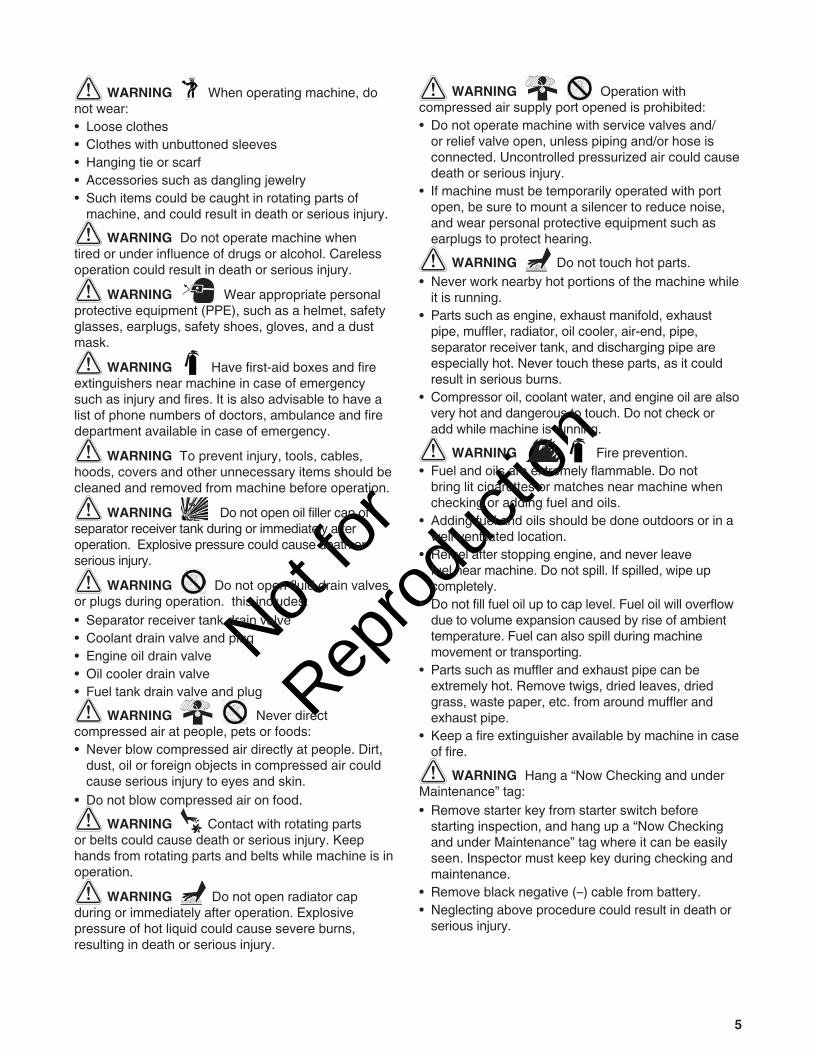
WARNING When operating machine, do not wear:• Loose clothes• Clothes with unbuttoned sleeves• Hanging tie or scarf• Accessories such as dangling jewelry• Such items could be caught in rotating parts of
machine, and could result in death or serious injury. WARNING Do not operate machine when
tired or under influence of drugs or alcohol. Careless operation could result in death or serious injury.
WARNING Wear appropriate personal protective equipment (PPE), such as a helmet, safety glasses, earplugs, safety shoes, gloves, and a dust mask.
WARNING Have first-aid boxes and fire extinguishers near machine in case of emergency such as injury and fires. It is also advisable to have a list of phone numbers of doctors, ambulance and fire department available in case of emergency.
WARNING To prevent injury, tools, cables, hoods, covers and other unnecessary items should be cleaned and removed from machine before operation.
WARNING Do not open oil filler cap of separator receiver tank during or immediately after operation. Explosive pressure could cause death or serious injury.
WARNING Do not open fluid drain valves or plugs during operation. this includes:• Separator receiver tank drain valve• Coolant drain valve and plug• Engine oil drain valve• Oil cooler drain valve• Fuel tank drain valve and plug
WARNING Never direct compressed air at people, pets or foods:• Never blow compressed air directly at people. Dirt,
dust, oil or foreign objects in compressed air could cause serious injury to eyes and skin.
• Do not blow compressed air on food. WARNING Contact with rotating parts
or belts could cause death or serious injury. Keep hands from rotating parts and belts while machine is in operation.
WARNING Do not open radiator cap during or immediately after operation. Explosive pressure of hot liquid could cause severe burns, resulting in death or serious injury.
WARNING Operation with compressed air supply port opened is prohibited:• Do not operate machine with service valves and/
or relief valve open, unless piping and/or hose is connected. Uncontrolled pressurized air could cause death or serious injury.
• If machine must be temporarily operated with port open, be sure to mount a silencer to reduce noise, and wear personal protective equipment such as earplugs to protect hearing.
WARNING Do not touch hot parts.• Never work nearby hot portions of the machine while
it is running.• Parts such as engine, exhaust manifold, exhaust
pipe, muffler, radiator, oil cooler, air-end, pipe, separator receiver tank, and discharging pipe are especially hot. Never touch these parts, as it could result in serious burns.
• Compressor oil, coolant water, and engine oil are also very hot and dangerous to touch. Do not check or add while machine is running.
WARNING Fire prevention.• Fuel and oils are extremely flammable. Do not
bring lit cigarettes or matches near machine when checking or adding fuel and oils.
• Adding fuel and oils should be done outdoors or in a well-ventilated location.
• Refuel after stopping engine, and never leave fuel near machine. Do not spill. If spilled, wipe up completely.
• Do not fill fuel oil up to cap level. Fuel oil will overflow due to volume expansion caused by rise of ambient temperature. Fuel can also spill during machine movement or transporting.
• Parts such as muffler and exhaust pipe can be extremely hot. Remove twigs, dried leaves, dried grass, waste paper, etc. from around muffler and exhaust pipe.
• Keep a fire extinguisher available by machine in case of fire.
WARNING Hang a “Now Checking and under Maintenance” tag:• Remove starter key from starter switch before
starting inspection, and hang up a “Now Checking and under Maintenance” tag where it can be easily seen. Inspector must keep key during checking and maintenance.
• Remove black negative (–) cable from battery.• Neglecting above procedure could result in death or
serious injury.

Not for
Reprod
uctio
n
6 ALLMAND.COM
WARNING When refilling separator receiver tank with compressor oil, stop engine, and make sure pressure gauge indicates 0 MPa, then gradually loosen oil filler cap. Residual pressure in separator receiver tank could cause extremely hot compressed air and oil to jet out, resulting in death or serious injury.
WARNING Be careful of high-pressurized blowout.• After stopping engine, make sure pressure gauge
indicates 0 MPa. Even when the gauge shows 0 MPa, open service valve to make sure there is no residual pressure in air piping.
• Residual air under pressure could result in serious injury.
WARNING Draining separator receiver tank.
• After stopping engine, confirm pressure gauge indicates 0 MPa and there is no residual pressure, then gradually open drain valve to drain compressor oil.
• Residual pressure in separator receiver tank could cause extremely hot compressed air and oil to jet out, resulting in death or serious injury.
WARNING Adjusting belt tension:• Attempting to adjust belt tension with machine
running could result in death or serious injury.• Stop engine, remove starter key, and remove black
negative (-) cable from battery before adjusting belt tension.
WARNING Hands off cooling fan:• Contact with cooling fan while machine is running
could result in death or serious injury.• Stop engine and remove starter key whenever
maintenance is to be performed near cooling fan. WARNING Wear safety glasses when
cleaning dust accumulated in such devices as air-filter by blowing compressed air.
WARNING Lighting apparatus: • If work site is dark, use lighting to illuminate work
area. Working without illumination could result in death or serious injury.
• Work lighting should be fitted with safety guard to protect against breakage.
• Do not allow work light to contact fuel or oils, as they could ignite, causing death or serious injury.
WARNING Opening coolant water drain valve cap:• Stop engine and let coolant water sufficiently cool
down before draining.• If drain valve is opened before coolant water is
cooled enough, hot water could jet out, resulting in death or serious injury.
CAUTION Refilling or draining engine oil:• Engine oil is extremely hot during and just after
operation.• Stop engine and wait 10 to 20 minutes before
checking, adding or draining engine oil. CAUTION Be sure to perform periodic
check of compressor oil and oil separator. Neglecting checks could cause overheating oil, resulting in a fire.
CAUTION Treatment of organic wastes.• Waste liquid from machine contains harmful material.
Do not discharge onto ground or into rivers, lakes or sea. Such material will contaminate the environment.
• Be sure to use an approved container to hold waste liquid from machine.
• Be sure to follow local, state or federal regulations when disposing of oil, fuel, coolant (antifreeze), filter, battery or other harmful materials.
NOTICE Parts of this machine contain sensitive electronic components. If welding work is required, disconnect any electronic equipment on the machine to prevent damage due to excessive current.
WARNING• The engine exhaust from this product contains
chemicals known to the State of California to cause cancer, birth defects, or other reproductive harm.
WARNING• Battery posts, terminals, and related accessories
contain lead and lead compounds, chemicals known to the State of California to cause cancer, birth defects, or other reproductive harm. Wash hands after handling.
Not for
Reprod
uctio
n
7
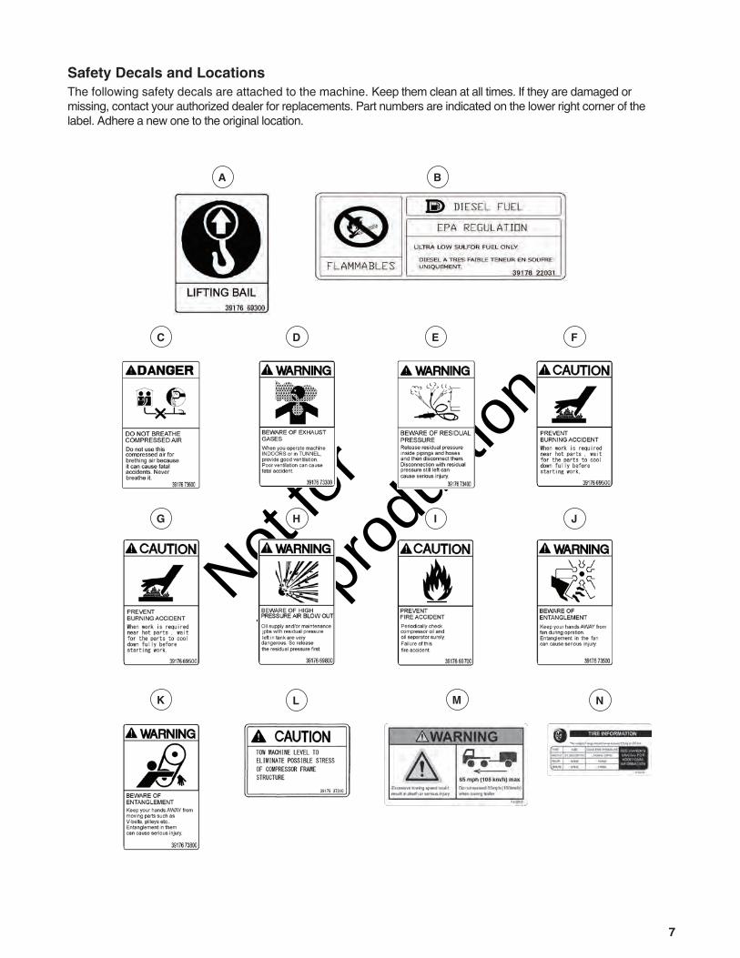
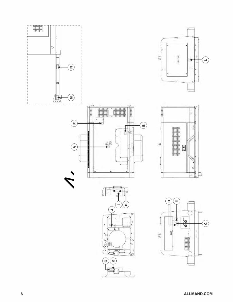
Safety Decals and LocationsThe following safety decals are attached to the machine. Keep them clean at all times. If they are damaged or missing, contact your authorized dealer for replacements. Part numbers are indicated on the lower right corner of the label. Adhere a new one to the original location.
WARNINGBeware of Exhaust Gases
When operating the machine INDOORS or in a TUNNEL,provide good ventilation. Poorventilation can cause fatal accidents.
800xxx
DANGERDo Not Breath Compressed Air
Do not use compressed air for breathing air because it can causefatal accidents.Never breathe it.
800xxx
DANGERBeware of Residual Pressure
Release residual pressure inside pipings and hoses and then disconnect them. Disconnection with residualpressure still left can cause serious injury. 800xxx
CAUTIONPrevent Burning Accident
Do not open radiator cap while it is still hot.
800xxx
CAUTIONPrevent Burning Accident
When work is requirednear hot parts, wait forthe parts to cool downfully before starting work.
800xxx
WARNINGBeware of High Pressure Air Blow Out
Oil supply and/or maintenancejobs with residual pressure leftin tank are very dangerous,so lease the residual pressure first.
800xxx
CAUTIONPrevent Furning Accident
Periodically check compressor oil and oil separator surely.Failure of this fire accident.
800xxx
WARNINGBeware of Entanglement
Keep hands AWAY fromfan during operation.Entanglement in the fancan cause serious injury.
800xxx
WARNINGBeware of Entanglement
Keep hands AWAY frommoving parts such as v-belts, pulleys, etc. Entanglement can causeserious injury.
800xxx
CAUTIONTOW MACHINE LEVEL TOELIMINATE POSSIBLESTRESS OF COMPRESSORFRAME STRUCTURE
800xxx
A
C F
I
L N
D
G J
E
H
K M
B
Not for
Reprod
uctio
n
8 ALLMAND.COM
L
B
C
FA
KG
ED
J
HI
NM

Not for
Reprod
uctio
n
9
Features and Controls Read this Operator’s Manual and safety rules before operating your towable compressor. Compare the illustrations with your towable compressor, to familiarize yourself with the locations of various controls and adjustments. Save this manual for future reference.
A - Pressure Control Valve — Keeps receiver tank pressure higher than 56 PSI (4 BAR) in tank.
B - Oil Separator — Separates oil mist mixed in compressed air.
C - Pressure Regulator — Regulates intake air volume.
D - Compressor Air Filter — Filters compressor air.E - Fuel Tank — Stores diesel fuel oil.F - Fuel -pre-filter — Filters impurities in fuel oil and
separates water from fuel.G - Engine Air Filter — Filters engine air.H - Engine Oil Filler Port — Location for adding engine oil to engine.I - Fuel Filter — Filters impurities from fuel.J - Air bleeding electromagnetic pump — Filters
impurities from fuel.
K - Bypass Valve — Maintains compressor oil temperature
L - Oil Cooler — Cools compressor oil circulating in system
M - Oil Cooler Drain Valve — Drains compressor oil from oil cooler and oil lines
N - Engine Oil Drain Valve — Drains engine oil.O - Engine Oil Filter — Filters engine oil.P - Engine Oil Level Gauge — Indicates engine oil
level.Q - Compressor Oil Level Gauge — Indicates
compressor oil level.R - Fuel Tank Drain Valve — Drains condensate
accumulated in fuel tank.S - Separator Receiver Tank Drain Valve — Drains
condensate from separator-receiver tank.T - Compressor Oil Filler Port — Location for adding
compressor oil.
A B C D E F G H I J K L
T S R Q P O N M
Not for
Reprod
uctio
n
10 ALLMAND.COM
A B C D E F G H
L K J I
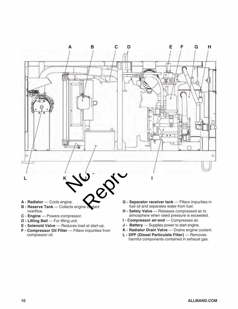
A - Radiator — Cools engine.B - Reserve Tank — Collects engine coolant
overflow.C - Engine — Powers compressor.D - Lifting Bail — For lifting unit.E - Solenoid Valve — Reduces load at start-up.F - Compressor Oil Filter — Filters impurities from
compressor oil.
G - Separator receiver tank — Filters impurities in fuel oil and separates water from fuel.
H - Safety Valve — Releases compressed air to atmosphere when rated pressure is exceeded.
I - Compressor air-end — Compresses air.J - Battery — Supplies power to start engine.K - Radiator Drain Valve — Drains engine coolant.L - DPF (Diesel Particulate Filter) — Removes
harmful components contained in exhaust gas.
Not for
Reprod
uctio
n
11
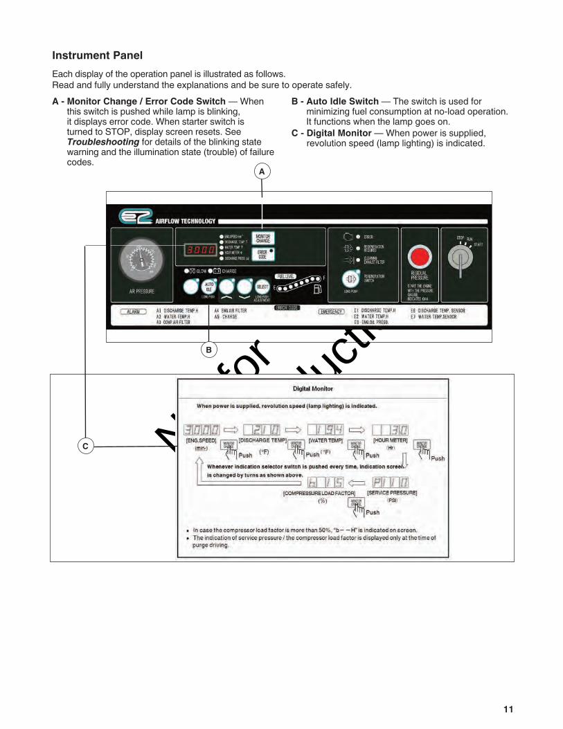
Instrument PanelEach display of the operation panel is illustrated as follows. Read and fully understand the explanations and be sure to operate safely.A - Monitor Change / Error Code Switch — When
this switch is pushed while lamp is blinking, it displays error code. When starter switch is turned to STOP, display screen resets. See Troubleshooting for details of the blinking state warning and the illumination state (trouble) of failure codes.
B - Auto Idle Switch — The switch is used for minimizing fuel consumption at no-load operation. It functions when the lamp goes on.
C - Digital Monitor — When power is supplied, revolution speed (lamp lighting) is indicated.
A
B
C
Not for
Reprod
uctio
n
12 ALLMAND.COM
Transporting and Set-Up Read entire Operator’s Manual before you attempt to setup, transport, or operate your new towable compressor.
Your towable compressor is ready for use after it has been properly setup with the recommended oil and fuel. If you have any problems with the setup of your towable compressor, contact your authorized dealer Setup Compressor
WARNING • Exhaust gas from the engine is poisonous, and could
cause death when inhaled.• Avoid using the machine in an insufficiently ventilated
building or tunnel.• Do not position the exhaust gas outlet in the direction
of a person or house.The machine should be operated in the following conditons: • Ambient temperature 5°F to 104°F. • Humidity less than 80%. • At altitudes lower than 4,291 ft. above sea level. • Set up the machine in a place with good
ventilation, lower temperature, and with surroundings as dry as possible.
• If more than two machines are placed parallel in operation, keep enough distance so that exhaust air from one machine does not affect the other.
• Set up the unit in an area where fresh air is always available.
• Keep enough space around the unit for inspection and maintenance access. WARNING The machine must be parked
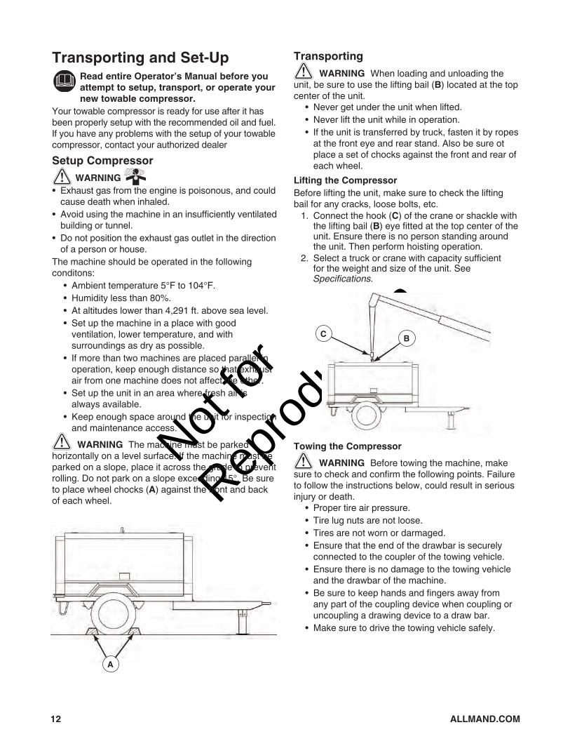
horizontally on a level surface. If the machine must be parked on a slope, place it across the grade to prevent rolling. Do not park on a slope exceeding 15°. Be sure to place wheel chocks (A) against the front and back of each wheel.
Transporting WARNING When loading and unloading the
unit, be sure to use the lifting bail (B) located at the top center of the unit. • Never get under the unit when lifted. • Never lift the unit while in operation. • If the unit is transferred by truck, fasten it by ropes
at the front eye and rear stand. Also be sure ot place a set of chocks against the front and rear of each wheel.
Lifting the CompressorBefore lifting the unit, make sure to check the lifting bail for any cracks, loose bolts, etc. 1. Connect the hook (C) of the crane or shackle with
the lifting bail (B) eye fitted at the top center of the unit. Ensure there is no person standing around the unit. Then perform hoisting operation.
2. Select a truck or crane with capacity sufficient for the weight and size of the unit. See Specifications.
Towing the Compressor WARNING Before towing the machine, make
sure to check and confirm the following points. Failure to follow the instructions below, could result in serious injury or death. • Proper tire air pressure. • Tire lug nuts are not loose. • Tires are not worn or darmaged. • Ensure that the end of the drawbar is securely
connected to the coupler of the towing vehicle. • Ensure there is no damage to the towing vehicle
and the drawbar of the machine. • Be sure to keep hands and fingers away from
any part of the coupling device when coupling or uncoupling a drawing device to a draw bar.
• Make sure to drive the towing vehicle safely.
A
BC

Not for
Reprod
uctio
n
13
OperationIf you have any problems operating your towable compressor, please contact your authorized dealer.
WARNING POISONOUS GAS HAZARD. Engine exhaust contains carbon monoxide, a poisonous gas that could kill you in minutes. You CANNOT smell it, see it, or taste it. Even if you do not smell exhaust fumes, you could still be exposed to carbon monoxide gas.• Operate this product ONLY outside far away from
windows, doors and vents to reduce the risk of carbon monoxide gas from accumulating and potentially being drawn towards occupied spaces.
• Install battery-operated carbon monoxide alarms or plug-in carbon monoxide alarms with battery back-up according to the manufacturer’s instructions. Smoke alarms cannot detect carbon monoxide gas.
• Avoid using the machine in insufficiently ventilated buildings, garages or tunnels, even if using fans for ventilation. Carbon monoxide can quickly build up in these spaces and can linger for hours, even after this product has shut off.
• ALWAYS place this product downwind and point the engine exhaust away from occupied spaces.
If you start to feel sick, dizzy, or weak while using this product, get to fresh air RIGHT AWAY. See a doctor. You may have carbon monoxide poisoning.
Oil RecommendationsEngine OilWe recommend the use of CJ-4 class engine oil or superior class for best performance. Using poor quality engine oil may shorten the life of the engine.Outdoor temperatures determine the proper oil viscosity for the engine.
Use the chart to select the best viscosity for the outdoor temperature range expected.
Note: When two ore more different brands of oil are mixed, its performance can be deteriorated. When it is expected to be used for a long period at light load (less than 20% load), it’s better to replace the oil with suitable oil.Compressor Oil Be sure to use the recommended compressor oil listed in the table blow.
• Even continuous oil replenishment cannot improve its deteriorated condition. Be sure to change the oil completely at every scheduled interval.
• Do not mix it with other brand oil, or it will cause poor perfromance and shorten the life of the compressor oil.
• Running the unit with old and deteriorated compressor oil will cause damage to bearings, or serious accident like ignition in a separator receiver tank. Be sure to change the oil completely at every scheduled interval.
point away from home
USE OUTDOORS - AVOID CARBON MONOXIDE POISONING
CARBON MONOXIDE ALARM(S)Install carbon monoxide alarms inside your home. Without working carbon monoxide alarms, you will not realize you are getting sick and dying from carbon monoxide poisoning.
˚F (˚C)
-13 (-25)
-4 (-20)
5(15)
32(0)
59 (15)
77 (25)
86 (30)
104(40)
Maker and Brand of Recommended Oil
Maker BrandHULS ANDEROL 3032MOBIL RARUS SHC 1024
TEXACO SYN-STAR DE32

Not for
Reprod
uctio
n
14 ALLMAND.COM
Checking / Adding Engine Oil WARNING Be sure to check the unit
before operation. If any issue is found, be sure to repair it before restarting the unit. Be sure to make daily checks before operation. Operating the unit without prior inspection could result in death or erious injury, or unit damage.NOTICE Unit should be on level before checking oil level. When you check oil level after initial operation, wait 10 to 20 minutes after stopping engine before checking the oil level. 1. Place compressor on a flat, level surface. 2. Clean area around oil fill, remove oil level gauge
(A), and wipe it with a clean cloth. 3. Re-insert the oil level gauge fully and pull it out
again. The oil level should be between LOW and HIGH (B).
B
A
4. If the oil level is below LOW, add engine oil to the oil filler port (C).
• While checking oil level, check also for contamination. If the oil is found dirty, contaminated or should it be changed according to the periodic inspection list, change the oil. See Maintenance.
• Excessive engine oil supply could cause engine output degradation. Therefore, never fill more than the HIGH level.
Checking / Adding Compressor Oil WARNING Refilling of compressor oil.
• When refilling the separator receiver tank with compressor oil, stop the engine, and make sure that the pressure gauge indicates 0psi (0bar) and there is no residual pressure in it, and then gradually loosen the oil filler cap for refilling oil.
• Should any residual pressure be left in the separator receiver tank, hot compressed air and hot compressor oil jetting out could cause burning or serious injury to persons nearby.
1. Place compressor on a flat, level surface. 2. After checking and confirming that the residual
pressure in separator receiver tank is 0 psi (0 bar), replenish the tank with compressor to between the upper limit and lower limit of oil level gauge when the machine is on. See Maintenance.
NOTICE Oil level drops when starting operation.Supply of excessive oil can cause deterioration of oil separation performance Never supply oil at a higher level than the upper level of oil level gauge.
Checking Coolant Level WARNING Taking off the radiator cap.
• Be sure to stop the machine and allow time to cool. Then loosen the radiator cap one notch. After the coolant water is sufficiently cooled and the inner pressure is released, take the cap off. If this procedure is neglected, the inner pressure can blow off the cap. Steam jetting out of the radiator could result in serious burns.
NOTICE Continuing operation at low coolant levels could result in damage to the radiator. 1. Check the coolant level (D) in the reserve tank. If it
is lower than the limit, open the cap and replenish the coolant. Level must be kept above LOW mark.
2. If there is a little or no coolant in the reserve tank, remove the radiator cap and check the coolant level. Supply coolant to the radiator and also the reserve tank, if necessary. See Maintenance.
C
D
HIGH
LOW

Not for
Reprod
uctio
n
15
Checking / Adding FuelFuel must meet these requirements:• Do not use such diesel fuel having higher sulfur
content above 0.0015%(15 ppm).• Use ultra-low sulfur diesel fuel only for diesel engine.• Use such diesel fuel which conforms to either
standard EN590 or ASTM D975.• Do not use kerosene. And never use fuel mixed with
kerosene.• Carbon residue content in fuel must be a low.• Follow the designated regulations to dispose of fuel.
NOTICE Fuel for DIESEL engines must have the following specific characteristics: • It must be free from even minute dust particles in it.
(Do not use such diesel fuel which has been long stored in a oil drum.)
• It must have optimum viscosity.• It must have high cetane number.• It must have high fluidity even at low temperature.• Carbon residue content in fuel must be a low.• It must not contain zinc and NA (sodium).
NOTICE Before starting operation, make sure to check the level of residual fuel so that fuel shortage during operation can be avoided. Drain condensate accumulated at the bottom of the fuel tank whenever necessary.
WARNING Fire Prevention.• Do not allow lit cigarettes or matches near fuel.• Fuel is extremely flammable and dangerous. Handle
with extreme care.• Refuel only after stopping engine, and never leave
open fuel can near machine. Do not spill. it fuel is spilled, wipe up completely.
• Refilling fuel tank should be done outdoors or in a well-ventilated location.
• Do not fill fuel oil up to the cap level. When fuel tank is filled to cap level, fuel oil will overflow due to volume expansion caused by rise of ambient temperature. Fuel may also spill due to machine movement or transporting.
Draining the Fuel Tank 1. Open the drain valve (B) fitted under the fuel tank
(A). Drain the condensate from the tank. 2. When completely drained, firmly close the drain
valve. 3. Drain the condensate in container and dispose
of condensate according to the designated regulations.
Close Open
B A

Not for
Reprod
uctio
n
16 ALLMAND.COM
Checking and Draining Pre-Filter for Condensate 1. When red float (A) under element (B) in Pre- filter
is raised up to upper level, drain water. 2. Turn fuel selector valve (C) to OFF position. 3. Loosen the drain valve (D) and drain out
condensed water inside.NOTE: Make sure to tighten the drain valve securely, after draining the condensate.
4. Drain the condensate in container and dispose of condensate according to the local, state and/or federal regulations.
Checklist Before Starting EngineReview the unit’s assembly to ensure you have performed all of the following. 1. Be sure to read Operator Safety and Operation
before operating the comprressor. 2. Make sure compressor is in place and secure. 3. Check that oil has been added to proper level. 4. Check wiring of each part for any loose
connections, damage to insulating sheathed portion, disconnection, and short circuit.
5. Check piping of each part for any loose connections, tears, and leaks.
6. Check each hose for tear and leaks. 7. Clean debris from interior of unit. Periodically
check the inside of the unit for debris. Any flammables such as chips of wood, dead leaves, and waste paper, especially near the muffler and exhaust pipe, should be removed.
WARNING Operation with compressed air supply port opened is prohibited.• Do not operate machine with service valves and
relief valve open unless air hoses and/or pipes are connected. Unregulated, high-pressurized air could result in serious injury.
• When the machine has to be unavoidably temporarily operated with its port open, be sure to mount a silencer to reduce noise and wear personal protective equipment (PPE) such as earplugs to prevent hearing damage.
WARNING • Keep the door closed and locked while running the
unit.• When the door has to be opened, be careful not to
touch portions that are rotating or very hot. Careless contact could result in serious injury.
• Pull the handle forward to open the door.• Be sure to close the door tightly so that it latches
securely.
ON
A
OFF
C
B
D

Not for
Reprod
uctio
n
17
Starting the CompressorNOTICE Be sure to let unit warm up after starting for smooth operation of the engine and the compressor. Do not operate the engine at full load immediately after it starts up. This will shorten the equipment life. • During machine warm-up, inspect the equipment
for any loose parts, fluid leakage, and other issues.
• Make sure that monitor lamps are off.To start compressor: 1. Make sure discharge air pressure gauge indicates
0 psi. 2. Fully close service valve. 3. Turn starter switch (A) to RUN position. The glow
lamp (B) will turn on.
4. When the glow lamp goes out, turn the starter switch to START position.
• Perform starter switch operation within 15 seconds.
• Make sure to wait longer than 2 minutes before starting next operation. Failure to wait the designated time could cause the starter motor to overheat, and could damage it.
• If residual pressure is present in the separator receiver tank, the residual pressure lamp (C) will illuminate, and the starter will not rotate. Make sure the residual pressure remains 0 psi (0 bar).
• According to engine cooling water temperature, the times in the table below are required.
5. Once engine starts, leave it running to warm up for 5 minutes. The discharge air pressure gauge (D) ranges from 44 to 102 psi (3 to 7 bar).
6. After warm-up is complete, open the service valve at the outlet of compressed air, and start service job.
D B AC
Engine Coolant Temperature
Required Preheating Time
Required Time for Starting Unloader Operation
Higher than 50°F 1 second 30 secondsLower than 50°F 20 seconds Shorter time either 120
seconds or the time when engine coolant temperature becomes higher than 50°F.

Not for
Reprod
uctio
n
18 ALLMAND.COM
Engine Fails to Start 1. If the engine fails to start after performing starting
procedure, steps 1 - 4, do not keep the starter running.
2. Set the starter switch to STOP, wait approximately 2 minutes, then repeat the startup procedure.
3. If the repeated startup procedure does not allow the engine to run, check for the following causes:
• No fuel • Clogged fuel filter • Discharge of battery or low cranking speed • Ambient temperature is too low Starting the Compressor at Low TemperatureNOTICE When operating compressor under cold weather conditions below 23°F (-5°C): • Use SAE10W-30 (CJ-4) for the engine oil. • When the unit is used in a cold region and
possible freezing is expected, it is recommended to use LLC (Antifreeze) for the coolant.
• Adjust mixing ratio of LLC (Antifreeze) with water according to the temperature.
• Use LLC (Antifreeze) within the range of its mixing ratio between 35 and 60%.
• If LLC (Antifreeze) in the water exceeds more than 60%, it may decrease its antifreezing effect. (Upon delivery from the works, LLC density is 55%).
• Use LLC (anti-freeze) which conforms to one of such standards: SAE JB13, SAE J1034 and ASTEM D3306.
• Battery should always be fully charged. • Follow the designated regulations to dispose of
LLC (Antifreeze).
When it is difficult to start engine in cold weather, complete the following steps: 1. Fully close the service valves. 2. Start engine by following steps 1 - 6 in Starting
the Compressor. CAUTION When operating the unit in
a low temperature, change engine oil, compressor oil, LLC , and diesel fuel according to the ambient temperature.Gauge Indication While Operating CompressorNOTICE Minimum discharge air pressure is 58 psi (4 bar) during operation. Continuing equipment operation at a lower pressure than the above pressure may cause overheating, since it affects the separation of lubricating oil inside the oil separator and reduces the oil flow to the compressor air-end, resulting in temperature rise. • Make sure to check that gauges or each
component of the compressor are properly working, or if there is any air-leak, oil-leak, water-leak or fuel-leak etc.
• During normal operation, each indication of instruments is shown in the table below. Refer to the table for daily checks.
Discharge Pressure Gauge
In Operation
Full Load * 58 to 100 psi(4 to 6.9 bar)
No Load(Unload)
* 116 to 131 psi( 8 to 9 bar)
At purge control
(AUTO IDLE)* 36 to 58 psi( 2.5 to 4bar)
* Values may vary slightly depending on the operating conditions and other factors.

Not for
Reprod
uctio
n
19
Capacity Control Device
Step Response
StartCompressed air flows into unloader chamber (A) because solenoid valve for purge control SV1 is opened at start-up. The pressure in chamber (A) rises soon to close unloader valve (A) fully and accordingly it can reduce the load at start-up.
Load Operation
After starting, SV1 is closed after automatic unloaded operation, and the air volume which is sent to chamber (A) increases and decreases according to the rise and drop of the discharge air pressure and consequently the opening width of the unloader valve is changed. Further, engine revolution (RPM) is changed by the pressure which PRS1 detects, and it steplessly controls the air volume in the range from 0 to 100%.
Suction Port Closing Unload Operation
When compressed air pressure exceeds the rated pressure with reduction of air consumption, PRS1 detects the pressure and it reduces engine speed (rpm) in proportion to the pressure rise, and it closes unloader valve at the same time. When compressor air-end becomes vacuum during unload operation, vacuum noise is caused. To prevent this noise, it opens vacuum relief valve by detection of secondary pressure of pressure regulator. Thus high vacuum condition of compressor air-end is prevented.
Purge Control Unload Opertion
When the certain set time (it can be changed.) has passed at lower pressure than the set negative pressure, detecting the negative pressure inside the compressor air end with a pressure sensor PRS2, solenoid valve SV1 opens and it closes unloader valve. At the same time, it functions to relieve the compressed air from separator receiver tank to the atmosphere and thus it lowers the pressure. Thus the compressor power is saved. When air consumption increases, and the pressure used for load drops below the set pressure, pressure sensor PRS3 detects it and it disengages the purge control (SV1 closes) to start full load operation.
Stop When stopping operation, it opens Auto relief valve to relieve the compressed air in separator receiver tank to atmosphere, detecting the pressure inside compressor air-end.
A
Not for
Reprod
uctio
n
20 ALLMAND.COM
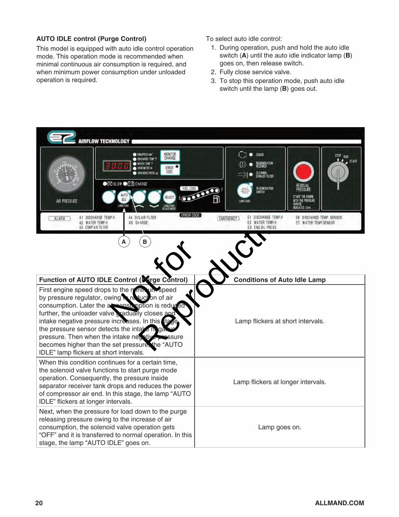
AUTO IDLE control (Purge Control)This model is equipped with auto idle control operation mode. This operation mode is recommended when minimal continuous air consumption is required, and when minimum power consumption under unloaded operation is required.
To select auto idle control: 1. During operation, push and hold the auto idle
switch (A) until the auto idle indicator lamp (B) goes on, then release switch.
2. Fully close service valve. 3. To stop this operation mode, push auto idle
switch until the lamp (B) goes out.
A B
Function of AUTO IDLE Control (Purge Control) Conditions of Auto Idle LampFirst engine speed drops to the minimum speed by pressure regulator, owing to reduction of air consumption. Later the air consumption is reduced further, the unloader valve gradually closes and intake negative pressure increases. In this stage, the pressure sensor detects the intake negative pressure. Then when the intake negative pressure becomes higher than the set pressure, the “AUTO IDLE” lamp flickers at short intervals.
Lamp flickers at short intervals.
When this condition continues for a certain time, the solenoid valve functions to start purge mode operation. Consequently, the pressure inside separator receiver tank drops and reduces the power of compressor air end. In this stage, the lamp “AUTO IDLE” flickers at longer intervals.
Lamp flickers at longer intervals.
Next, when the pressure for load down to the purge releasing pressure owing to the increase of air consumption, the solenoid valve operation gets “OFF” and it is transferred to normal operation. In this stage, the lamp “AUTO IDLE” goes on.
Lamp goes on.

Not for
Reprod
uctio
n
21
Stopping the Compressor 1. Close the service valve completely and operate
the machine about 5 minutes, until it cools down. 2. Turn the starter switch to STOP position to stop
the engine. 3. Remove the key from the compressor every time
you stop the engine. Keep the key and be careful not to lose it.
• Unless all service valves are fully closed upon stopping operation, the compressed air will be sent in reverse direction in the hoses (pipes) connected to air tools and relieved to atmosphere continuously through the auto-relief valve. When re-starting operation next time, compressed air will be jetted out through service valves.
Air Bleeding in Fuel LineShould the machine stop due to fuel shortage, perform air bleeding according to the following • Replenish fuel. • When starter switch is turned to RUN position,
electromagnetic pump starts to automatically bleed air in fuel line.
• Air bleeding is completed about 1 minute.DPF (Diesel Particulate Filter) Regeneration (Purge)
WARNING • During DPF regeneration operation, exhaust gas of
high temperature is discharged. Check and confirm that there are no persons or flammables near by. Exhaust gases could cause severe burns, and could result in a fire.
• During regeneration operation in closed spaces, carefully monitor carbon monoxide levels to avoid carbon monoxide poisoning.
When regeneration control is begun and finished, noise of engine air intake throttle and EGR opening width adjustment is sometimes caused. This is normal.The smell of the exhaust gas caused during regeneration operation is different from that of diesel fuel exhaust.Passive RegenerationSoot collected in the DPF is burnt automatically because of high temperature during normal operation under heavy load application.
Active (Automatic) Regeneration• Operation under light load application or no load
requires active regeneration, because engine exhaust temperature is not high enough to burn soot collected in the DPF.
• During active regeneration mode operation, it is possible to continue servicing job.
Active Regeneration Mode 1. Cleaning exhaust filter lamp (A) turns ON. 2. The regeneration process will last for about 30
minutes. 3. The lamp will turn OFF when regeneration is
complete.Note: Time required for regeneration depends on load factor and ambient temperature.NOTICE• Do not stop engine during active regeneration
operation, except for unavoidable conditions.
A

Not for
Reprod
uctio
n
22 ALLMAND.COM
Manual (Forced) RegenerationDuring no-load or almost no-load operation, or when ambient temperature is very low, incomplete soot combustion occurs. If operated continuously in these same conditions, manual, or forced, regeneration may be required. In this case: 1. REGENERATION REQUIRED lamp (A) and
ERROR lamp (E) go on. At the same time, REGENERATION SWITCH lamp (C) flashes. Engine speed automatically changes to 1,350 min-1.
2. Press and hold REGENERATION SWITCH (B)longer than 3 seconds.
3. REGENERATION REQUIRED lamp turns off and CLEANING EXHAUST FILTER lamp (D) turns ON. Then REGENERATION SWITCH lamp (C) stays on instead of flashing. At this time, manual regeneration operation starts.
4. Engine speed gradually increases up to approximately 2,220 min-1.
5. Manual regeneration operation is performed in about 30 minutes.
Note: Time of regeneration varies upon the ambient temperature. 6. When manual regeneration is completed, all
lamps turn off, and both normal engine speed and normal operation resume.
• If continuing operation for approximately ten hours without conducting manual regeneration once REGENERATION REQUIRED lamp (A) is lit, machine will go into low idling operation only. At this point, it will be impossible to conduct manual regeneration, and it will be necessary to clean the DPF. If this occurs, contact your authorized dealer.
WARNING When DPF regeneration lamp goes on, take immediate specified action to conduct manual regeneration. If it is continuously operated without manual regeneration, excessive soot will accumulate and it could damage DPF due to abnormal burning, and it could cause a fire.NOTICE Do not stop engine during manual (forced) regeneration operation, except for unavoidable conditions.
A B C D E

Not for
Reprod
uctio
n
23
MaintenanceRegular maintenance of the compressor and engine will improve the performance and extend the life of the compressor. See any qualified dealer for service.Compressor Maintenance ScheduleFollow the hourly or calendar intervals, whichever occurs first. More frequent service is required when operating in adverse conditions noted below.
1Contact an authorized dealer. Item requires expert knowledge. 2Should be replaced every 2 years even if they are not in disorder within theirperiodical maintenance interval because their materials will change or become degraded as time passes. 3 Should be replaced every 3 years because their materials will change or become degraded as time passes. 4If it is found good, it is possible to continue to use it.
Engine Maintenance ScheduleRefer to engine operation manual for inspection and maintenance of engine.Undercarriage Maintenance Schedule
Every 300 Hours or 3 Months • Supply grease to trailer hub bearing • Check drawbar hardware for proper tightnessEvery 1,000 Hours • Check undercarriage bracket hardware for
proper tightness • Check wheel lug nuts for proper tightness
Daily • Check compressor oil level • Drain separator receiver tank • Check looseness in pipe connecting part, and
wear and tear of pipe. • Check oil, water, fuel and air leak • Check functions of all instruments and devicesEvery 250 Hours • Clean and change air filter elementFirst Time and Every 350 Hours • Change compressor oil • Change compressor oil filterEvery 500 Hours • Change compressor oil • Clean strainer in the scavenging orifice • Clean and change air filter elementEvery 1,000 Hours • Change compressor oil filter • Clean outside of the oil coolerEvery 2,000 Hours
• Change oil separator1
• Change nylon tubes1,2
Every 3,000 Hours • Change unloader o-ring1,2
• Change pressure regulator1
• Check rubber hose1,2
• Check consumable parts of the auto-relief valve1,2
• Check consumable parts of the vacuum relief valve1,2
• Performance check of pressure control valve1,
• Check and change o-ring and pressure control valve piston1
• Inspect solenoid valve1,4
Every 8,000 Hours
• Change oil seal and bearing1
Not for
Reprod
uctio
n
24 ALLMAND.COM
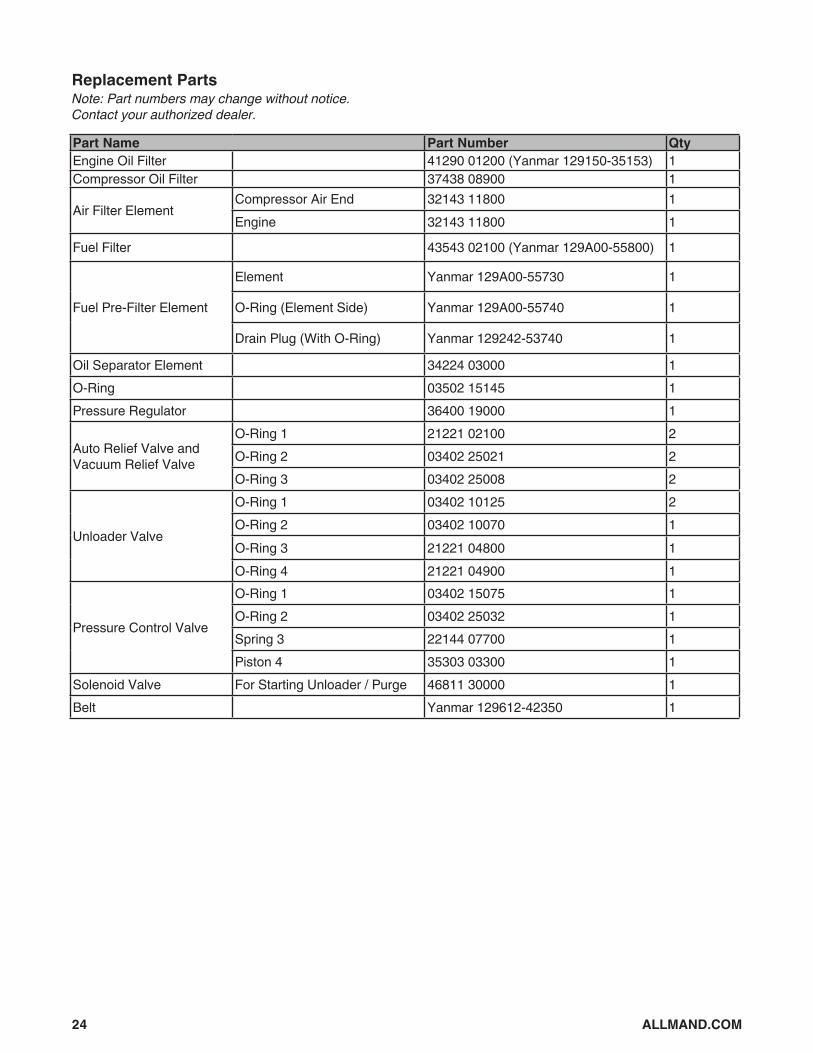
Replacement PartsNote: Part numbers may change without notice. Contact your authorized dealer.
Part Name Part Number QtyEngine Oil Filter 41290 01200 (Yanmar 129150-35153) 1Compressor Oil Filter 37438 08900 1
Air Filter ElementCompressor Air End 32143 11800 1Engine 32143 11800 1
Fuel Filter 43543 02100 (Yanmar 129A00-55800) 1
Fuel Pre-Filter Element
Element Yanmar 129A00-55730 1
O-Ring (Element Side) Yanmar 129A00-55740 1
Drain Plug (With O-Ring) Yanmar 129242-53740 1
Oil Separator Element 34224 03000 1O-Ring 03502 15145 1Pressure Regulator 36400 19000 1
Auto Relief Valve and Vacuum Relief Valve
O-Ring 1 21221 02100 2O-Ring 2 03402 25021 2O-Ring 3 03402 25008 2
Unloader Valve
O-Ring 1 03402 10125 2O-Ring 2 03402 10070 1O-Ring 3 21221 04800 1O-Ring 4 21221 04900 1
Pressure Control Valve
O-Ring 1 03402 15075 1O-Ring 2 03402 25032 1Spring 3 22144 07700 1Piston 4 35303 03300 1
Solenoid Valve For Starting Unloader / Purge 46811 30000 1Belt Yanmar 129612-42350 1

Not for
Reprod
uctio
n
25
Maintenance ItemsChange Engine Oil
WARNING Engine oil is very hot and highly pressurized during or just after operation. Hot oil could blow out of the tank and can cause serious injury.
NOTICE Never supply more engine oil than specified level. Excessive engine oil could cause engine damage.1. After stopping engine, wait 10 to 20 minutes until
engine oil cools off.2. Remove drain plug (A), open drain valve (B), and
discharge engine oil drain. Dispose of used oil according to local, state and/or federal regulations.
3. When oil is completely drained, close drain valve and replace drain plug.
4. Remove engine oil filler cap (C), and fill engine with oil. See Checking / Adding Engine Oil in Operation. (Oil capacity: approx. 0.9 gal.(3.4L))
5. Check oil level: Remove dipstick (D), wipe clean, replace, then remove. Oil level should read between marks on lower end of dipstick (E). Add as needed.
AB
C
D
E
D
Change Engine Oil Filter(For part number, see Replacement Parts)1. Remove old oil filter (F) using a filter wrench.2. Apply a light coating of oil on oil filter seal (G).3. Install new oil filter until seal contacts oil pump, then
tighten 1 additional turn by hand.4. After installing oil filter, check for leaks. Tighten as
necessary.
F
G
Battery Maintenance WARNING
• Keep flames away from battery.• Battery may generate hydrogen gas and may
explode.• Charging should be done at a well-ventilated place.• Do not spark near the battery nor light a match, nor
bring lit cigarette and match close to the battery.• Do not check the battery by short-circuiting the
positive and negative terminals.
Not for
Reprod
uctio
n
26 ALLMAND.COM
• Do not operate machine or charge battery with low electrolyte level. Doing so may damage battery, or may cause explosion.
• Add distilled water so that electrolyte level reads between “UPPER” and “LOWER” level.
• Do not charge frozen battery. Otherwise it may explode. If battery is frozen, warm it up until the battery temperature becomes 16°C to 30°C.
• Battery electrolyte is dilute sulfuric acid.• Mishandling battery could cause severe burns.• Wear protective gloves and safety glasses when
handling battery.• If battery electrolyte contacts clothes or skin, wash
immediately with large amount of water.• If battery electrolyte gets into eyes, flush with plenty
of water and seek immediate medical attention.• Dispose of battery according to local, state and/or
federal regulations.Check Battery ElectrolyteStandard battery:1. Check battery electrolyte level. If low, add distilled
water.2. Measure specific gravity of battery electrolyte. If
below 1.24, recharge battery. See Charge Battery.Maintenance-free battery:1. Check indicator on top surface of battery.2. If indicator shows that charge is needed, recharge
battery.Charge Battery1. Disconnect cables between battery and unit, black
negative (-) cable first, and charge battery (A) with a 12-volt battery charger (B). Do not charge two batteries at the same time.
2. Be sure not to connect (+) and (–) terminals backwards.
3. Read operation manual of battery charger before use.
B A
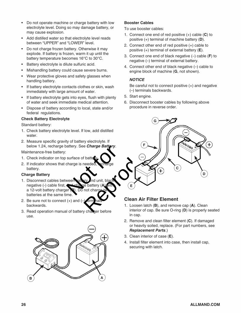
Booster CablesTo use booster cables:1. Connect one end of red positive (+) cable (C) to
positive (+) terminal of machine battery (D).2. Connect other end of red positive (+) cable to
positive (+) terminal of external battery (E).3. Connect one end of black negative (–) cable (F) to
negative (–) terminal of external battery.4. Connect other end of black negative (–) cable to
engine block of machine (G, not shown).
NOTICE Be careful not to connect positive (+) and negative
(–) terminals backwards.5. Start engine.6. Disconnect booster cables by following above
procedure in reverse order.
E
F
G
DC
Clean Air Filter Element1. Loosen latch (B), and remove cap (A). Clean
interior of cap. Be sure O-ring (D) is properly seated in cap.
2. Remove and clean filter element (C). If damaged or heavily soiled, replace. (For part numbers, see Replacement Parts.)
3. Clean interior of case (E). 4. Install filter element into case, then install cap,
securing with latch.

Not for
Reprod
uctio
n
27
C
D
E
B
A
Change Compressor Oil WARNING
• When you refill the separator receiver tank with compressor oil, stop the engine, and make sure that the pressure gauge indicates 0psi (0bar) and there is no residual pressure in it, and then gradually loosen the oil filler cap for refilling oil.
• Note residual pressure in the receiver tank could force both extremely hot compressed air and oil to jet out and you may be scalded or seriously injured.
• Even continuous oil replenishment cannot improve its deteriorated condition. Be sure to change the oil completely at every scheduled interval.
• Do not mix it with other brand oil, or it will cause poor performance and shorten the life of the compressor oil. (But fresh compressor oil could accept a mixture of small amount of different brands.)
• Running the unit with old and deteriorated compressor oil will cause damage to bearings, or serious accident like ignition in a separator receiver tank. Be sure to change the oil completely at every scheduled interval.
• Follow the designated regulations to dispose of compressor oil.
1. After residual pressure is completely relieved from separator receiver tank, remove oil filler cap (F) and open drain valve (G) to drain oil. Then open drain valve of oil cooler to drain oil accumulated in bottom of oil cooler.
NOTE: Warm oil drains more quickly.2. After compressor oil is completely drained, close
drain valve.3. Refill with fresh compressor oil to upper limit of level
gauge, then replace oil filler cap. (Oil Capacity: Approx 3.96 gal (15L).) Check o-ring (H) of oil filler cap for damage or wear. Replace if necessary.
4. Start engine and allow to run for a minute or two, then replenish oil to fill any shortage. Repeat this procedure for 1 to 2 times to check if oil level has reached appropriate level. Be careful not to overfill the oil.
F
G
H
Change Compressor Oil FilterFor filter part number, see Replacement Parts.1. Remove old filter (A) using a filter wrench.2. Apply a light coating of oil on filter seal (B).3. Install new filter until seal contacts pump, then
tighten 1 additional turn by hand.4. After installing filter, check for leaks. Tighten as
necessary.
A
B

Not for
Reprod
uctio
n
28 ALLMAND.COM
Clean Oil Separator Strainer1. Remove pipe (C) using a spanner.2. Remove bushing (D).3. Remove strainer (E).4. Wash strainer in diesel oil and carefully blow out
debris with compressed air. (Be sure to wear safety goggles.)
5. Install strainer by reversing steps 1 through 3.
C
DE
Change Air Filter ElementFor filter element part number, see Replacement Parts.1. Loosen latch (G), and remove cap (F). Clean
interior of cap. Be sure O-ring (I) is properly seated in cap.
2. Dispose of old filter element (H), replacing with new.
3. Clean interior of case (J). 4. Install filter element into case, then install cap,
securing with latch.
H
I
J
G
F
Clean / Change Fuel Pre-Filter ElementFor filter element part number, see Replacement Parts.Turn fuel selector valve (A) to OFF position.Loosen drain valve (B) and drain out condensed water.Turn cup (C) counterclockwise to remove. Wipe out split fuel.Remove float (D) inside cup.Wash element (E) and inside of cup with new fuel. Check element and o-ring, and replace if worn, broken or damaged.If air is found in fuel pipe, turn starter switch to RUN position and loosen air bleeding bolt (F) to bleed air. Tighten after bleeding.Drain condensate, and dispose according to local, state and/or federal regulations.
FA
CD
B
E
OFF
ON
INSTALL
REMOVE

Not for
Reprod
uctio
n
29
Change Fuel FilterFor filter part number, see Replacement Parts.1. Remove old filter (G) using a filter wrench.2. Apply a light coating of oil on filter seal (H).3. Install new filter until seal contacts pump, then
tighten 1 additional turn by hand.4. After installing filter, check for leaks. Tighten as
necessary.
G
H
Clean Outside Of Radiator / Oil CoolerGently clean fin tubes (I) of radiator / oil cooler of dirt and debris.
NOTICEDo not use high pressure cleaning equipment, as it may damage fin tubes.
I
Clean Inside Of RadiatorContact your authorized dealer.
Grease Trailer Hub BearingContact your authorized dealer.
Change Coolant WARNING
• Be sure to stop the machine and allow time to cool. Then loosen the radiator cap one notch. After the coolant water is sufficiently cooled and the inner pressure is released, take the cap off.
If this procedure is neglected, the inner pressure can blow off the cap. Steam jetting out of the radiator could result in causing scalding. Follow this procedure under all circumstances.
• LLC (Antifreeze) is a toxic material. If swallowed, seek immediate medical attention. Do
not induce vomiting. If in eyes, wash eyes with clean running water and
seek immediate medical attention. When storing, store in an approved container,
clearly labeled ‘LLC (Antifreeze) inside’, away from children.
• Keep away from fire and flame. 1. To drain coolant, remove radiator cap (A). Remove
operation side radiator drain plug (B) and open drain valve (C, engine side) for drainage.
2. After draining, close drain valve and replace drain plug, then supply coolant through filler port (A). (Coolant capacity: approx. 1.93 gal (7.3L).)
3. After filling with coolant, run machine in unloaded condition for approximately 2 to 3 minutes. Stop machine and check coolant level. Add as needed.
Not for
Reprod
uctio
n
30 ALLMAND.COM
4. Dispose of used coolant according to local, state and/or federal regulations.
A
B
C
Change Oil SeparatorContact your authorized dealer.
Change Nylon TubesContact your authorized dealer.
Change Fuel HoseContact your authorized dealer.
Change Pressure RegulatorContact your authorized dealer.
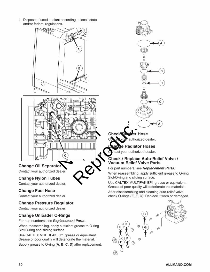
Change Unloader O-RingsFor part numbers, see Replacement Parts.When reassembling, apply sufficient grease to O-ring Slot/O-ring and sliding surface.Use CALTEX MULTIFAK EP1 grease or equivalent. Grease of poor quality will deteriorate the material.Supply grease to O-ring (A, B, C, D) after replacement.
A
B
D
C
A
Check Rubber HoseContact your authorized dealer.
Change Radiator HosesContact your authorized dealer.
Check / Replace Auto-Relief Valve / Vacuum Relief Valve PartsFor part numbers, see Replacement Parts.When reassembling, apply sufficient grease to O-ring Slot/O-ring and sliding surface.Use CALTEX MULTIFAK EP1 grease or equivalent. Grease of poor quality will deteriorate the material.After disassembling and cleaning auto-relief valve, check O-rings (E, F, G). Replace if worn or damaged.
EF
G
G
FE

Not for
Reprod
uctio
n
31
Check Pressure Control ValveClose stop valve and fully open service valve while machine is running. Make sure discharge pressure gauge shows between 49 and 68 psi (3.4 and 4.7 bar).If pressure is lower than 49 psi (3.4 bar) or higher than 68 psi (4.7 bar), contact your authorized dealer.
Check Pressure Control Valve O-Rings / PistonContact your authorized dealer.
Check Drawbar Hardware for Proper TightnessCheck tightness of drawbar hardware (H). Tighten to 140 lb-ft (190 Nm).
H
Check Undercarriage Bracket Hardware for Correct TightnessCheck tightness of undercarriage bracket hardware (A). Tighten to 100 lb-ft (136 Nm).
A
Check Wheel Lug Nuts / Tire PressureCheck tightness of wheel lug nuts (B). Tighten to 80 lb-ft (108 Nm).Also check tire pressure. Adjust to 65 psi (4.5 bar).
B
StoragePreparation for Long-term StorageIf the machine is left unused or not operated longer than six months:• Store in a clean, dry place. Avoid leaving machine
outside.• Remove battery from machine, if possible, and
store in a dry place.• Charge battery (at least once every month).• Drain engine oil from machine.• Drain coolant and fuel from machine.*• Seal engine, air-intake port and other openings
with vinyl sheet, packing tape, etc., to protect from moisture and dust.
• Perform any necessary repairs or maintenance items.
Disposal of ProductsIn case of disposal of this unit, at first drain and dispose of all fluids according to local, state and/or federal regulations. For further information, please contact your authorized dealer.

Not for
Reprod
uctio
n
32 ALLMAND.COM
TroubleshootingIndicator Lamps and Warning / Emergency Displays
Indicator Lamp
Item Indication Remedy Monitor
Glow Glow plug preheating ------
Charge Alternator not charging Check WiringCheck alternator
Warning Display
Item Failure Code Indication Remedy
Discharge Temp H A1 Lamp flickers when air temperature at outlet of air-end
reaches 239°F (115°C). See Troubleshooting Chart
Water Temp H A2 Lamp flickers when coolant temperature reaches 221°F (105°C).
Comp. Air Filter A3Lamp comes on when air filter gets clogged and suction resistance increases above 6.2 kPa Clean or replace
Eng. Air Filter A4
Charge A5 Alternator not chargingSee Troubleshooting Chart
Emergency Display
Item Failure Code Indication Remedy
Discharge Temp H E1 Lamp displays when air temperature at outlet of air-end
reaches 248°F (120°C).
See Troubleshooting Chart
Water Temp H E2 Lamp displays when coolant temperature reaches 230°F (110°C).
Eng. Oil Pressure E3 Lamp goes on when engine oil pressure drops below 7.3
psi (0.5 bar)Discharge Air Temp Sensor Disconnection
E6 Air temperature sensor at outlet of compressor air end disconnected
Coolant Temp Sensor Disconnection
E7 Coolant temperature sensor disconnected

Not for
Reprod
uctio
n
33
Troubleshooting Chart
Problem Cause Correction
Low starter revolution speed 1. Battery low or dead 1. Check battery; charge or replace as needed
Starter rotates but engine does not start
1. Fuel filter clogging 2. Fuel pre-filter clogging 3. No diesel fuel 4. Air mixing in fuel pipings 5. Failure of engine stop solenoid
1. Clean / replace 2. Clean / replace 3. Add diesel fuel 4. Bleed air 5. Contact authorized dealer
Discharge air pressure does not reach 100 psi (6.9 bar)
1. Pressure regulator needs adjustment
2. Pressure regulator trouble.
1. Adjust 2. Contact authorized dealer
Engine does not reach maximum speed
1. Failure of engine controller 2. Unloader orifice clogging 3. Engine trouble 4. Fuel filter clogged 5. Water accumulated in fuel pre-
filter 6. Air filter element clogged
1. Contact authorized dealer 2. Clean 3. .Contact authorized dealer 4. Clean / replace 5. Drain 6. Clean / replace
Revolution drops before discharge air pressure reaches 100 psi (6.9 bar)
1. Pressure regulator needs adjustment
2. Pressure regulator issue 3. Unloader orifice clogged
1. Adjust 2. Contact authorized dealer 3. Check / clean
Engine does not reach minimum revolution at unload
1. Failure of engine controller 2. Failure of accelerator controller
1. Contact authorized dealer 2. Contact authorized dealer
Safety valve relieves at unload
1. Pressure regulator needs adjustment
2. Unloader valve / seat damage 3. Faulty safety valve 4. Faulty engine speed sensor
1. Adjust 2. Contact authorized dealer 3. Contact authorized dealer 4. Contact authorized dealer
Oil mixes in air (poor oil separation)
1. Scavenging orifice strainer clogged
2. Excessive oil in separator receiver tank
3. Low discharge pressure 4. Oil separator deteriorated
1. Clean 2. Drain 3. Check unloader 4. Contact authorized dealer
Insufficient free air delivery
1. Air filter element clogged 2. Unloader valve cannot fully
open 3. Engine does not reach rather
speed
1. Clean / replace 2. Contact authorized dealer 3. Contact authorized dealer

Not for
Reprod
uctio
n
34 ALLMAND.COM
Data Adjustment
Problem Cause Correction
Low engine oil pressure, engine stops
1. Engine oil level low 2. Engine oil filter clogged 3. Faulty oil pressure switch 4. Loose or broken wire
1. Add engine oil 2. Replace 3. Contact authorized dealer 4. Connect; contact authorized
dealer
Coolant temperature high, engine stops
1. Radiator clogged 2. Faulty thermostat 3. Faulty coolant temp switch 4. Belt slipping 5. Low coolant level 6. Loose or broken wire 7. Coolant temp sensor
disconnected
1. Change coolant 2. Contact authorized dealer 3. Contact authorized dealer 4. Contact authorized dealer 5. Add coolant 6. Connect; contact authorized
dealer 7. Contact authorized dealer
Discharge temperature high, engine stops
1. Oil cooler clogged 2. Oil filter clogged 3. Faulty discharge air temp switch 4. Belt slipping 5. Compressor oil level low 6. Loose or broken wire 7. Discharge air temp sensor
disconnected
1. Change coolant 2. Replace 3. Contact authorized dealer 4. Contact authorized dealer 5. Add compressor oil 6. Connect; contact authorized
dealer 7. Contact authorized dealer
Engine monitor alarm lamp lit 1. Engine trouble 1. Contact authorized dealer
Contact your authorized dealers for all other issues.
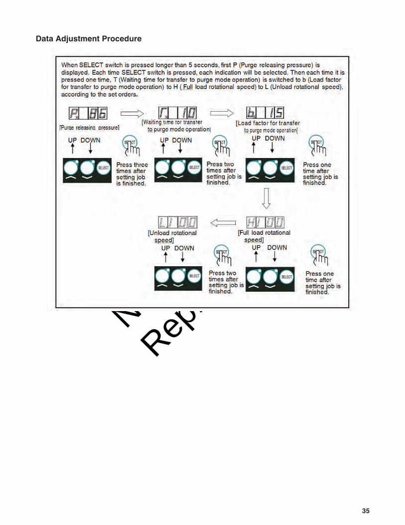
No. Item Indication Unit Primary Set Value Set Value Range
1 Purge releasing pressure PSI 86 70 ~ 100
2 Waiting time for transfer to purge mode operation Second 10 7 ~ 60
3 Load factor for transfer to purge mode operation % 15 5 ~ 30
4
High-speed side correction(Full load rotational speed)
min-1 100 0 ~ 200
5Low-speed side correction(Unload rotational speed)
min-1 100 0 ~ 200
Not for
Reprod
uctio
n
35
Data Adjustment Procedure

Not for
Reprod
uctio
n
36 ALLMAND.COM
SpecificationsModel 185 CFM
Compressor
Type Single-stage oil cooled, screw type compressor
Free Air Delivery cfm (m3/min) 185 (5.2)
Working Pressure psi (bar) 100 (6.9)
Lubricating System Forced lubrication by compressed pressure
Driving System Direct driving with gear coupling
Receiver Tank Capacity cu in (m3) 1,221 (0.021)
Lubricating Oil Capacity gal (L) 3.96 (15)
Engine
Model Yanmar 4TNV88C-DHKSType Water-cooled 4-cycle direct injection
No Cylinders, Bore Stroke in (mm) 4 - 3.46 x 3.54 in (4 - 88 mm x 90 mm)
Total Displacement cu in (L) 133.6 (2.189)
Rated Output (Gross)kW / min-1 35.5 / 3,000
Rated Output (Net) 34.0 / 3,000
Lubricating Oil Capacity gal (L) 0.9 (3.1)Coolant Capacity (including Radiator) gal (L) 1.80 (6.8)
Battery 95D31 (12V)Fuel Tank Capacity gal (L) 24 (90)
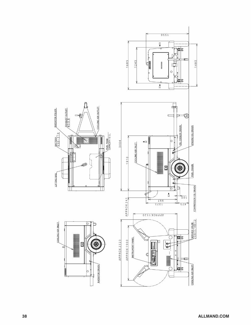
General Specifications
Overall Length in (mm) 134 (3,404)Overall Length (Bonnet Only) in (mm) 75.2 (1,910)
Overall Width in (mm) 66.3 (1,685)Overall Height in (mm) 61 (1,550)Net Dry Mass lb (kg) 2050 (930)Operating Mass lb (kg) 2,450 (1,111)

Not for
Reprod
uctio
n
37
Not for
Reprod
uctio
n
38 ALLMAND.COM

Not for
Reprod
uctio
n
39
Wiring Diagram

Not for
Reprod
uctio
n
40 ALLMAND.COM
Piping DiagramAir Piping - Compressor Oil Piping

Not for
Reprod
uctio
n
41
Air Piping - Compressor Oil Piping

Not for
Reprod
uctio
n
42 ALLMAND.COM
STO
PTIM
E
: : : : : : : : : : : : : : : : : : : : : :
STA
RT
TIM
E
: : : : : : : : : : : : : : : : : : : : : :
.
.
.
.
.
.
.
.
.
.
.
.
.
.
.
.
.
.
.
.
.
.
.
.
.
.
.
.
.
.
.
.
.
.
.
.
.
.
.
.
.
.
.
.
REM
AR
KS
(IN
SP
EC
TIO
N/P
AR
T C
HA
NG
E
HIS
TO
RY
ETC
.)
RA
TED
RP
M
(rpm
,min
-1)
DIS
CH
AR
GE
AIR
P
RESS.(P
SI)
OP
ER
ATIO
N
LO
G
OP
ER
ATIO
N
DA
TE
OP
ER
ATIO
N T
IME
AM
BIE
NT
TEM
P.(
F)
EN
G.O
IL
REP
LA
CEM
EN
T
HO
UR
(h
)
TO
TA
L
OP
ER
ATIO
N
HO
UR
S
(h)
CO
OLA
NT
TEM
P.(
F)
DIS
CH
AR
GE
AIR
TEM
P.
(
F)
CO
MP
.OIL
SU
PP
LY(g
al.)
°
°
°

Not for
Reprod
uctio
n
43
STO
PTIM
E
: : : : : : : : : : : : : : : : : : : : : :
STA
RT
TIM
E
: : : : : : : : : : : : : : : : : : : : : :
.
.
.
.
.
.
.
.
.
.
.
.
.
.
.
.
.
.
.
.
.
.
.
.
.
.
.
.
.
.
.
.
.
.
.
.
.
.
.
.
.
.
.
.
OP
ER
ATIO
N
LO
G
OP
ER
ATIO
N
DA
TE
OP
ER
ATIO
N T
IME
AM
BIE
NT
TEM
P.(℃
)
EN
G.O
IL
REP
LA
CEM
EN
T
HO
UR
(h
)
TO
TA
L
OP
ER
ATIO
N
HO
UR
S
(h)
CO
OLA
NT
TEM
P.(℃
)
DIS
CH
AR
GE
AIR
TEM
P.
(℃
)
CO
MP
.OIL
SU
PP
LY(L
)
REM
AR
KS
(IN
SP
EC
TIO
N/P
AR
T C
HA
NG
E
HIS
TO
RY
ETC
.)
RA
TED
RP
M
(rpm
,min
-1)
DIS
CH
AR
GE
AIR
P
RESS.(M
Pa)

Not for
Reprod
uctio
n
44 ALLMAND.COM
Noise Emission
This section pertains only to machines distributed within the United States.
WARNING!Tampering with Noise Control System Prohibited
Federal law prohibits the following acts or the causing thereof:1. The removal or rendering inoperative by any persons, other than for purposes
of maintenance, repair, or replacement, of any device or element of designincorporated into any new compressor for the purpose of noise control prior toits sale or delivery to the ultimate purchaser or while it is in use; or
2. the use of the compressor after such device or element of design has beenremoved or rendered inoperative by any person.
Among those acts included in the prohibition against tampering are these:3. Removal or rendering inoperative any of the following:
a.the engine exhaust system or parts thereofb.the air intake system or parts thereof c.enclosure or parts thereof
4. Removal of any of the following: a.fan shroud b.vibration mounts c.sound absorption material
5. Operation of the compressor with any of the enclosure doors open.
Compressor Noise Emission Control InformationA. The removal or rendering inoperative, other than for the purpose of
maintenance, repair, or replacement of any noise control device or element ofdesign incorporated into this compressor in compliance with noise control act;
B. The use of this compressor after such device or element of design has beenremoved or rendered inoperative.
NOTE: The above information applies only to units that are built incompliance with the U.S. Environmental Protection Agency.
The Manufacturer reserves the right to make changes or add improvements without noticeand without incurring any obligation to make such changes or add such improvements to products sold previously.The Purchaser is urged to include the above provisions in any agreement for any resale of this compressor.

Not for
Reprod
uctio
n
45
Noise Emission Control Maintenance Log
The Noise Control Act of 1972 (86 Stat. 1234) prohibits tampering with the noise control system of any compressor manufactured and sold under the above regulations, specifically the following acts or the causing thereof:(1) the removal or rendering inoperative by any persons, other than for purposes of maintenance, repair, or replacement, of any device or element of design incorporated into new compressor for the purpose of noise control prior to its sale or delivery to the ultimate purchaser or while it is in use; or (2) the use of the compressor after such device or element of design has been removed or rendered inoperative by any person.
Noise Emission WarrantyThe manufacturer warrants to the ultimate purchaser and each subsequent purchaser that this air compressor was designed, built and equipped to conform at the time of sale to the first retail purchaser, with all applicable U.S. EPA Noise Control Regulations.This warranty is not limited to any particular part, component, or system of the air compressor. Defects in the design, assembly or in any part, component, or system of the compressor which, at the time of sale to the first retail purchaser, caused noise emissions to exceed Federal Standards are covered by this warranty for the life of the air compressor.
IntroductionThe unit for which this Maintenance Log is provided conforms to U.S. E.P.A. Regulations for Noise Emissions, applicable to Portable Air Compressors.The purpose of this book is to provide (1) the Maintenance Performance Schedule for all required noise emission controls and (2) space so that the purchaser or owner can record what maintenance was done, by whom, where and when. The Maintenance Schedule and detailed instructions on the maintenance items are given on following page.
COMPRESSOR MODEL __________________________SERIAL NO. ___________________________________USER UNIT NO. ________________________________
UNIT IDENTIFICATION
Engine Make & Model: ________________Serial No.: _________________________Purchaser or Owner: _________________Address: __________________________
DEALER OR DISTRIBUTOR FROM WHOM PURCHASED:______________________________________________________________________________________________________Date Purchased: ____________________

Not for
Reprod
uctio
n
46 ALLMAND.COM
A. Compressed Air LeaksCorrect all compressed air leaks during the first shutdown period after discovery. If severe enough to cause serious noise problems and efficiency loss, shut down immediately and correct the leak(s).
B. Safety and Control SystemsRepair or replace all safety and control systems or circuits as malfunction occurs. No compressor should be operated with either system bypassed, disabled, or nonfunctional.
C. Acoustic MaterialsIn daily inspections, observe these materials. Maintain all acoustic material as nearly as possible in its original condition. Repair or replace all sections that have: 1) sustained damage, 2) have partially separated from panels to which they were attached, 3) are missing, or have otherwise deteriorated due to severe operating or storage conditions.
D. FastenersAll fasteners such as hinges, nuts, bolts, clamps, screws, rivets, and latches should be inspected for looseness after each 100 hours of operation. They should be retightened, repaired, or if missing, replaced immediately to prevent subsequent damage and noise emission increase.
E. Enclosure PanelsEnclosure panels should also be inspected at 100 hour operational intervals. All panels that are warped, punctured, torn, or otherwise
deformed, such that their noise containment function is reduced, should be repaired or replaced before the next operation interval. Doors, access panels, and hatch closures especially, should be checked and adjusted at this time to insure continuous seating between gasket or acoustic material and the mating frame.
F. Air Intake and Engine ExhaustEngine and compressor air intake and engine exhaust systems should be inspected after each 100 hours of operation for loose, damaged, or deteriorated components. Repairs or replacements should be made before the next period of use.
G. Cooling SystemsAll components of the cooling system for engine water and compressor oil should be inspected every 250 hours of use. Any discrepancies found should be corrected before placing the unit back in operation. Unrestricted airflow over the radiator and oil cooler must be maintained at all times during operation.
H. Isolation MountsEngine/airend isolation mounts should be inspected after each 250 hours of operation. Those mounts with cracks or splits in the molded rubber, or with bent or broken bolts due to operation or storage in severe environments, all should be replaced with equivalent parts.
I. Engine OperationInspect and maintain engine condition and operation as recommended in the manuals supplied by the engine manufacturer.
J. Fuels and LubricantsUse only the types and grades of fuels and lubricants recommended in the Equipmentand Engine Manufacturer’s Operator and Maintenance Manuals.
Maintenance ScheduleItem Area PeriodA.B.C.D.E.F.G.H.I.J.
Compressed Air LeaksSafety and Control SystemsAcoustic MaterialsFastenersEnclosure PanelsAir Intake & Engine ExhaustCooling SystemsIsolation MountsEngine OperationFuels & Lubricants
As DetectedAs DetectedDaily100 hours100 hours100 hours250 hours250 hoursSee Operator’s ManualSee Operator’s Manual

Not for
Reprod
uctio
n
47
Maintenance Record For Noise Emission Control
Item No. Description Of Work Hourmeter
ReadingMaint / Inspect
DateLocation
City / StateWork Done By (Name)

Not for
Reprod
uctio
n