181i Fabricator - Gases, Welding, Industrial, MRO & Safety · PDF fileFabricator Multi proceSS...
86
Art # A-10107 181i Service Manual Revision: AB Issue Date: April 06, 2012 Manual No.: 0-5152 Operating Features: FABRICATOR MULTI PROCESS WELDING INVERTER
Transcript of 181i Fabricator - Gases, Welding, Industrial, MRO & Safety · PDF fileFabricator Multi proceSS...
Art # A-10107
181i
Service ManualRevision: AB Issue Date: April 06, 2012 Manual No.: 0-5152Operating Features:
FabricatorMulti proceSS weldinginverter

WE APPRECIATE YOUR BUSINESS!Congratulations on your new Thermal Arc product. We are proud to have you as our customer and will strive to provide you with the best service and reliability in the industry. This product is backed by our extensive warranty and world-wide service net-work. To locate your nearest distributor or service agency call +44 (0) 1257 261 755, or visit us on the web at www.Thermalarc.com.
This Service Manual has been designed to instruct you on the correct use and operation of your Thermal Arc product. Your satisfaction with this product and its safe operation is our ultimate concern. Therefore please take the time to read the entire manual, especially the Safety Precautions. They will help you to avoid potential hazards that may exist when working with this product. We have made every effort to provide you with accurate instructions, drawings, and photographs of the product(s) we used when writing this manual. However errors do occur and we apologize if there are any contained in this manual.
Due to our constant effort to bring you the best products, we may make an improvement that does not get reflected in the manual. If you are ever in doubt about what you see or read in this manual with the product you received, then check for a newer version of the manual on our website or contact our customer support for assistance.
YOU ARE IN GOOD COMPANY!The Brand of Choice for Contractors and Fabricators Worldwide.Thermal Arc is a Global Brand of Arc Welding Products for Thermadyne Industries Inc. We manufacture and supply to major welding industry sectors worldwide including; Manufacturing, Construction, Mining, Automotive, Aerospace, Engineering, Rural and DIY/Hobbyist.
We distinguish ourselves from our competition through market-leading, dependable products that have stood the test of time. We pride ourselves on technical innovation, competitive prices, excellent delivery, superior customer service and technical support, together with excellence in sales and marketing expertise.
Above all, we are committed to develop technologically advanced prod-ucts to achieve a safer working environment within the welding industry.
! WARNINGS
Read and understand this entire Manual and your employer’s safety practices before installing, operating, or servicing the equipment.
While the information contained in this Manual represents the Manufacturer’s best judgement, the Manufacturer assumes no liability for its use.
Service Manual Number 0-5152 for:Thermal Arc Fabricator 181i Inverter Plant Part Number W1003186Thermal Arc Fabricator 181i Inverter Power Source (unpacked) Part Number W1003185
Published by:Thermadyne Industries, Inc.16052 Swingley Ridge Road, Suite 300St Louis, Mo63017USA
www.thermadyne.com
Copyright 2011 byThermadyne Industries, Inc.
All rights reserved.
Reproduction of this work, in whole or in part, without written permission of the pub-lisher is prohibited.
The publisher does not assume and hereby disclaims any liability to any party for any loss or damage caused by any error or omission in this Manual, whether such error results from negligence, accident, or any other cause.
Publication Date: April 27, 2011Revision AB Date: April 06, 2012
Record the following information for Warranty purposes:
Where Purchased: ____________________________________
Purchase Date: ____________________________________
Equipment Serial #: ____________________________________
TABLE OF CONTENTS
SECTION 1: SAFETY INSTRUCTIONS AND WARNINGS ............................................... 1-1
1.01 Arc Welding Hazards ....................................................................................... 1-11.02 Principal Safety Standards .............................................................................. 1-41.03 Declaration of Conformity ............................................................................... 1-51.04 Symbol Chart .................................................................................................. 1-61.05 Servicing Hazards ........................................................................................... 1-71.06 EMF Information ............................................................................................. 1-8
SECTION 2: INTRODUCTION .............................................................................. 2-1
2.01 How to Use This Manual ................................................................................. 2-12.02 Equipment Identification ................................................................................. 2-12.03 Receipt of Equipment ...................................................................................... 2-12.04 Description ..................................................................................................... 2-1 2.05 Transportation Methods .................................................................................. 2-12.06 Packaged Items .............................................................................................. 2-2
SECTION 3: SAFETY AND INSTALLATION ............................................................... 3-1
3.01 Duty Cycle ....................................................................................................... 3-13.02 Specifications ................................................................................................. 3-23.03 Environment ................................................................................................... 3-23.04 Location .......................................................................................................... 3-33.05 Ventilation ....................................................................................................... 3-33.06 Mains Supply Voltage Requirements .............................................................. 3-33.07 Electrical Input Connections ........................................................................... 3-33.08 Electromagnetic Compatibility ........................................................................ 3-43.09 Volt-Ampere Curves ........................................................................................ 3-6
SECTION 4: OPERATION ................................................................................... 4-1
4.01 Fabricator 181i Power Source Controls, Indicators and Features ................... 4-14.02 Attaching the Tweco WeldSkill 180 Torch (Euro) ............................................ 4-64.03 Installing 100mm Diameter Spool ................................................................. 4-64.04 Installing 200mm Diameter Spool .................................................................. 4-74.05 Inserting Wire into the Wire Feed Mechanism ................................................ 4-84.06 Feed Roller Pressure Adjustment .................................................................... 4-94.07 Changing the Feed Roll ................................................................................. 4-104.08 Wire Reel Brake ............................................................................................ 4-104.09 Setup for MIG (GMAW) Welding with Gas Shielded MIG Wire ..................... 4-114.10 Setup for MIG (GMAW) Welding with Gasless MIG Wire .............................. 4-124.11 Setup for TIG (GTAW) Welding ..................................................................... 4-134.12 Setup for Manual Arc (MMA) Welding ........................................................ 4-144.13 Leak Testing the System ............................................................................... 4-15
SECTION 5: THEORY OF OPERATION .................................................................... 5-1
5.01 Inverter Design ..................................................................................................... 5-1
TABLE OF CONTENTS
SECTION 6: TROUBLESHOOTING ........................................................................ 6-1
6.01 Basic Troubleshooting-Power Source Faults ................................................... 6-16.02 Checking Unit Before Applying Power ............................................................ 6-26.03 Tools Needed for Troubleshooting and Servicing ............................................ 6-26.04 Case Removal ................................................................................................. 6-36.05 Clear Cover Sheet Removal ............................................................................. 6-46.06 Visually Inspect ............................................................................................... 6-46.07 Preliminary DC Bus measurement of the main inverter board ........................ 6-46.08 Preliminary check of the main inverter board ................................................. 6-56.09 Check main On / Off Switch ............................................................................ 6-76.10 Check main input rectifier ............................................................................... 6-76.11 DC Bus voltage measurement ......................................................................... 6-86.12 PCB Connectors .............................................................................................. 6-96.13 DIP switch settings, Control PCB .................................................................. 6-146.14 Calibration .................................................................................................... 6-156.15 Main Circuit Description ............................................................................... 6-186.16 Circuit Diagram ............................................................................................. 6-20
SECTION 7: DISASSEMBLY PROCEDURE ............................................................... 7-1
7.01 Safety Precautions for Disassembly ............................................................... 7-17.02 Control Board Removal ................................................................................... 7-27.03 Front Panel Assembly Removal ...................................................................... 7-47.04 Front Panel (Operator Interface) Circuit Board PCB3 Removal ....................... 7-67.05 Back Panel Removal ....................................................................................... 7-77.06 Power Switch S1 and Power Cord Removal ................................................... 7-87.07 Base Panel Removal ....................................................................................... 7-9
SECTION 8: ASSEMBLY PROCEDURES .................................................................. 8-1
8.01 Installing Base Board ...................................................................................... 8-18.02 Installing Back Panel ....................................................................................... 8-28.03 Installing Front Panel ...................................................................................... 8-48.04 Installing Main Control Panel and Clear Cover Sheet ...................................... 8-68.05 Installing Case ................................................................................................ 8-8
SECTION 9: REPLACEMENT PARTS ..................................................................... 9-1
9.01 Tweco WeldSkill 180A MIG Torch ........................................................................ 9-19.02 Power Source ...................................................................................................... 9-2
SECTION 10: OPTIONS AND ACCESSORIES ...........................................................10-1
10.01 Options and Accessories .............................................................................. 10-1
THERMAL ARC - LIMITED WARRANTY TERMS
TERMS OF WARRANTY – JANUARY 2011

SAFETY INSTRUCTIONS AND WARNINGS FABRICATOR 181i
Manual 0-5152 1-1 Safety Instructions and Warnings
1.01 Arc Welding Hazards
WARNING
ELECTRIC SHOCK can kill.
Touching live electrical parts can cause fatal shocks or severe burns. The electrode and work circuit is electrically live whenever the output is on. The input power circuit and machine internal circuits are also live when power is on. In semiautomatic or automatic wire welding, the wire, wire reel, drive roll housing, and all metal parts touching the welding wire are electri-cally live. Incorrectly installed or improperly grounded equipment is a hazard
1. Do not touch live electrical parts.
2. Wear dry, hole-free insulating gloves and body protection.
3. Insulate yourself from work and ground using dry insulating mats or covers.
4. Disconnect input power or stop engine before installing or servicing this equipment. Lock input power disconnect switch open, or remove line fuses so power cannot be turned on ac-cidentally.
5. Properly install and ground this equipment according to its Owner’s Manual and national, state, and local codes.
6. Turn off all equipment when not in use. Disconnect power to equipment if it will be left unattended or out of service.
7. Use fully insulated electrode holders. Never dip holder in water to cool it or lay it down on the ground or the work surface. Do not touch holders connected to two welding machines at the same time or touch other people with the holder or electrode.
8. Do not use worn, damaged, undersized, or poorly spliced cables.
9. Do not wrap cables around your body.
10. Ground the workpiece to a good electrical (earth) ground.
11. Do not touch electrode while in contact with the work (ground) circuit.
12. Use only well-maintained equipment. Repair or replace damaged parts at once.
13. In confined spaces or damp locations, do not use a welder with AC output unless it is equipped with a voltage reducer. Use equipment with DC output.
14. Wear a safety harness to prevent falling if working above floor level.
15. Keep all panels and covers securely in place.
WARNING
ARC RAYS can burn eyes and skin; NOISE can dam-age hearing.
Arc rays from the welding process produce intense heat and strong ultraviolet rays that can burn eyes and skin. Noise from some processes can damage hearing.
1. Use a Welding Helmet or Welding Faceshield fitted with a proper shade of filter (see ANSI Z49.1 and EN60974-1 listed in Safety Standards) to protect your face and eyes when welding or watching.
2. Wear approved safety glasses. Side shields recommended.
3. Use protective screens or barriers to protect others from flash and glare; warn others not to watch the arc.
4. Wear protective clothing made from durable, flame-resistant material (wool and leather) and foot protection.
5. Use approved ear plugs or ear muffs if noise level is high.
6. Never wear contact lenses while welding.
WARNING
FUMES AND GASES can be hazardous to your health.
Welding produces fumes and gases. Breathing these fumes and gases can be hazardous to your health.
1. Keep your head out of the fumes. Do not breath the fumes.
SECTION 1: SAFETY INSTRUCTIONS AND WARNINGS
! WARNING
PROTECT YOURSELF AND OTHERS FROM POSSIBLE SERIOUS INJURY OR DEATH. KEEP CHILDREN AWAY. PACEMAKER WEARERS KEEP AWAY UNTIL CONSULTING YOUR DOCTOR. DO NOT LOSE THESE INSTRUCTIONS. READ OPERATING/INSTRUCTION MANUAL BEFORE INSTALLING, OPERATING OR SERVICING THIS EQUIPMENT.
Welding products and welding processes can cause serious injury or death, or damage to other equipment or property, if the operator does not strictly observe all safety rules and take precautionary actions.
Safe practices have developed from past experience in the use of welding and cutting. These practices must be learned through study and training before using this equipment. Some of these practices apply to equipment connected to power lines; other practices apply to engine driven equipment. Anyone not having extensive training in welding and cutting practices should not attempt to weld.
Safe practices are outlined in the European Standard EN60974-1 entitled: Safety in welding and allied processes Part 2: Electrical. This publication and other guides to what you should learn before operating this equipment are listed at the end of these safety precautions. HAVE ALL INSTALLATION, OPERATION, MAINTENANCE, AND REPAIR WORK PERFORMED ONLY BY QUALIFIED PEOPLE.
Safety Instructions and Warnings 1-2 Manual 0-5152
FABRICATOR 181i SAFETY INSTRUCTIONS AND WARNINGS2. If inside, ventilate the area and/or use exhaust at the arc to
remove welding fumes and gases.
3. If ventilation is poor, use an approved air-supplied respirator.
4. Read the Material Safety Data Sheets (MSDSs) and the manu-facturer’s instruction for metals, consumables, coatings, and cleaners.
5. Work in a confined space only if it is well ventilated, or while wearing an air-supplied respirator. Shielding gases used for welding can displace air causing injury or death. Be sure the breathing air is safe.
6. Do not weld in locations near degreasing, cleaning, or spraying operations. The heat and rays of the arc can react with vapours to form highly toxic and irritating gases.
7. Do not weld on coated metals, such as galvanized, lead, or cadmium plated steel, unless the coating is removed from the weld area, the area is well ventilated, and if necessary, while wearing an air-supplied respirator. The coatings and any metals containing these elements can give off toxic fumes if welded.
WARNING
WELDING can cause fire or explosion.
Sparks and spatter fly off from the welding arc. The flying sparks and hot metal, weld spatter, hot work-piece, and hot equipment can cause fires and burns. Accidental contact of electrode or welding wire to metal objects can cause sparks, overheating, or fire.
1. Protect yourself and others from flying sparks and hot metal.
2. Do not weld where flying sparks can strike flammable material.
3. Remove all flammables within 10.7m ( 35 ft ) of the welding arc. If this is not possible, tightly cover them with approved covers.
4. Be alert that welding sparks and hot materials from welding can easily go through small cracks and openings to adjacent areas.
5. Watch for fire, and keep a fire extinguisher nearby.
6. Be aware that welding on a ceiling, floor, bulkhead, or partition can cause fire on the hidden side.
7. Do not weld on closed containers such as tanks or drums.
8. Connect work cable to the work as close to the welding area as practical to prevent welding current from travelling long, possibly unknown paths and causing electric shock and fire hazards.
9. Do not use welder to thaw frozen pipes.
10. Remove stick electrode from holder or cut off welding wire at contact tip when not in use.
WARNING
FLYING SPARKS AND HOT METAL can cause injury.
Chipping and grinding cause flying metal. As welds cool, they can throw off slag.
1. Wear approved face shield or safety goggles. Side shields recommended.
2. Wear proper body protection to protect skin.
WARNING
CYLINDERS can explode if damaged.
Shielding gas cylinders contain gas under high pres-sure. If damaged, a cylinder can explode. Since gas cylinders are normally part of the welding process, be sure to treat them carefully.
1. Protect compressed gas cylinders from excessive heat, me-chanical shocks, and arcs.
2. Install and secure cylinders in an upright position by chaining them to a stationary support or equipment cylinder rack to prevent falling or tipping.
3. Keep cylinders away from any welding or other electrical circuits.
4. Never allow a welding electrode to touch any cylinder.
5. Use only correct shielding gas cylinders, regulators, hoses, and fittings designed for the specific application; maintain them and associated parts in good condition.
6. Turn face away from valve outlet when opening cylinder valve.
7. Keep protective cap in place over valve except when cylinder is in use or connected for use.
8. Read and follow instructions on compressed gas cylinders, associated equipment, and CGA publication P-1 listed in Safety Standards.
SAFETY INSTRUCTIONS AND WARNINGS FABRICATOR 181i
Manual 0-5152 1-3 Safety Instructions and Warnings
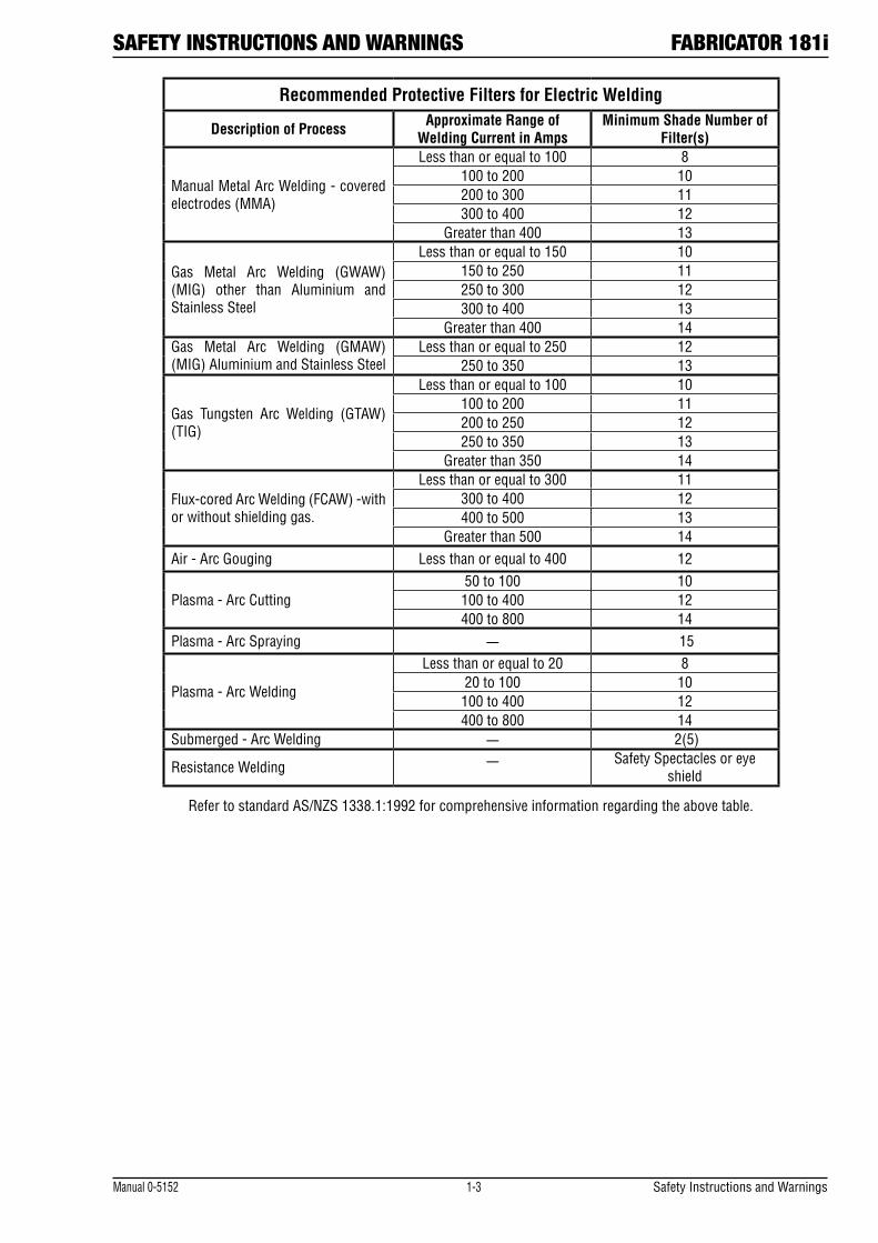
Recommended Protective Filters for Electric Welding
Description of Process Approximate Range of Welding Current in Amps
Minimum Shade Number of Filter(s)
Manual Metal Arc Welding - covered electrodes (MMA)
Less than or equal to 100 8 100 to 200 10 200 to 300 11 300 to 400 12
Greater than 400 13
Gas Metal Arc Welding (GWAW) (MIG) other than Aluminium and Stainless Steel
Less than or equal to 150 10 150 to 250 11 250 to 300 12 300 to 400 13
Greater than 400 14 Gas Metal Arc Welding (GMAW) (MIG) Aluminium and Stainless Steel
Less than or equal to 250 12 250 to 350 13
Gas Tungsten Arc Welding (GTAW) (TIG)
Less than or equal to 100 10 100 to 200 11 200 to 250 12 250 to 350 13
Greater than 350 14
Flux-cored Arc Welding (FCAW) -with or without shielding gas.
Less than or equal to 300 11 300 to 400 12 400 to 500 13
Greater than 500 14 Air - Arc Gouging Less than or equal to 400 12
Plasma - Arc Cutting 50 to 100 10 100 to 400 12 400 to 800 14
Plasma - Arc Spraying — 15
Plasma - Arc Welding
Less than or equal to 20 8 20 to 100 10 100 to 400 12 400 to 800 14
Submerged - Arc Welding — 2(5)
Resistance Welding — Safety Spectacles or eye shield
Refer to standard AS/NZS 1338.1:1992 for comprehensive information regarding the above table.
Safety Instructions and Warnings 1-4 Manual 0-5152
FABRICATOR 181i SAFETY INSTRUCTIONS AND WARNINGS
WARNING
MOVING PARTS can cause injury.
Moving parts, such as fans, rotors, and belts can cut fingers and hands and catch loose clothing.
1. Keep all doors, panels, covers, and guards closed and securely in place.
2. Stop engine before installing or connecting unit.
3. Have only qualified people remove guards or covers for main-tenance and troubleshooting as necessary.
4. To prevent accidental starting during servicing, disconnect negative (-) battery cable from battery.
5. Keep hands, hair, loose clothing, and tools away from moving parts.
6. Reinstall panels or guards and close doors when servicing is finished and before starting engine.
WARNING
This product, when used for welding or cutting, pro-duces fumes or gases which contain chemicals know to the State of California to cause birth defects and, in some cases, cancer. (California Health & Safety code Sec. 25249.5 et seq.)
NOTE
Considerations About Welding And The Effects of Low Frequency Electric and Magnetic Fields
The following is a quotation from the General Conclusions Section of the U.S. Congress, Office of Technology Assessment, Biological Effects of Power Frequency Electric & Magnetic Fields - Background Paper, OTA-BP-E-63 (Washington, DC: U.S. Government Printing Office, May 1989): “...there is now a very large volume of scientific findings based on experiments at the cellular level and from studies with animals and people which clearly establish that low frequency magnetic fields and interact with, and produce changes in, biological systems. While most of this work is of very high quality, the results are complex. Current scientific understanding does not yet allow us to interpret the evidence in a single coherent framework. Even more frustrating, it does not yet allow us to draw definite conclu-sions about questions of possible risk or to offer clear science-based advice on strategies to minimize or avoid potential risks.”
To reduce magnetic fields in the workplace, use the following procedures.
1. Keep cables close together by twisting or taping them.
2. Arrange cables to one side and away from the operator.
3. Do not coil or drape cable around the body.
4. Keep welding power source and cables as far away from body as practical.
ABOUT PACEMAKERS:
The above procedures are among those also normally recommended for pacemaker wearers. Consult your doctor for complete information.
1.02 Principal Safety StandardsSafety in Welding and Cutting, ANSI Standard Z49.1, from American Welding Society, 550 N.W. LeJeune Rd., Miami, FL 33126.
Safety and Health Standards, OSHA 29 CFR 1910, from Superinten-dent of Documents, U.S. Government Printing Office, Washington, D.C. 20402.
Recommended Safe Practices for the Preparation for Welding and Cutting of Containers That Have Held Hazardous Substances, Ameri-can Welding Society Standard AWS F4.1, from American Welding Society, 550 N.W. LeJeune Rd., Miami, FL 33126.
National Electrical Code, NFPA Standard 70, from National Fire Protection Association, Batterymarch Park, Quincy, MA 02269.
Safe Handling of Compressed Gases in Cylinders, CGA Pamphlet P-1, from Compressed Gas Association, 1235 Jefferson Davis Highway, Suite 501, Arlington, VA 22202.
Code for Safety in Welding and Cutting, CSA Standard W117.2, from Canadian Standards Association, Standards Sales, 178 Rexdale Boulevard, Rexdale, Ontario, Canada M9W 1R3.
Safe Practices for Occupation and Educational Eye and Face Pro-tection, ANSI Standard Z87.1, from American National Standards Institute, 1430 Broadway, New York, NY 10018.
Cutting and Welding Processes, NFPA Standard 51B, from National Fire Protection Association, Batterymarch Park, Quincy, MA 02269.
Safety in welding and allied processes Part 1: Fire Precautions, EN 60974-1 from SAI Global Limited, www.saiglobal.com.
Safety in welding and allied processes Part 2: Electrical, EN 60974-1 from SAI Global Limited, www.saiglobal.com.
Filters for eye protectors - Filters for protection against radiation generated in welding and allied operations AS/NZS 1338.1:1992 from SAI Global Limited, www.saiglobal.com.
SAFETY INSTRUCTIONS AND WARNINGS FABRICATOR 181i
Manual 0-5152 1-5 Safety Instructions and Warnings
1.03 Declaration of ConformityManufacturer: Thermadyne Corporation Address: 16052 Swingley Ridge Road, Suite 300 St Louis, Mo63017 USA
Description of equipment: Welding Equipment (GMAW, FCAW, GTAW, MMA) including, but not limited to Thermal Arc Fabricator 181i Multi Process Welding Inverter and associated accessories.
Serial numbers are unique with each individual piece of equipment and details description, parts used to manufacture a unit and date of manufacture.
The equipment conforms to all applicable aspects and regulations of the ‘Low Voltage Directive’ (Directive 73/23/EU), as recently changed in Directive 93/68/EU and to the National legislation for the enforcement of the Directive.
National Standard and Technical Specifications
The product is designed and manufactured to a number of standards and technical requirements among them are:
• IEC60974-10applicabletoIndustrialEquipment-genericemissionsandregulations.
• EN60974-1Safetyinweldingandalliedprocesses.
• EN60974-1/IEC60974-1applicabletoweldingequipmentandassociatedaccessories.
•Extensiveproductdesignverificationisconductedatthemanufacturingfacilityaspartoftheroutinedesignandmanufacturingprocess, to ensure the product is safe and performs as specified. Rigorous testing is incorporated into the manufacturing process to ensure the manufactured product meets or exceeds all design specifications.
•2002/95/EC RoHS directive
! WARNING
This equipment does not comply with IEC 61000-3-12. If it is connected to a public low voltage system, it is the responsibility of the installer or user of the equipment to ensure, by consultation with the distribution network operator if necessary, that the equipment may be connected.
Thermadyne has been manufacturing and merchandising an extensive equipment range with superior performance, ultra safe operation and world class quality for more than 30 years and will continue to achieve excellence.
Manufacturers responsible representative in Europe: Steve Ward Operations Director Thermadyne Europe Europa Building Chorley N Industrial Park Chorley, Lancashire, England PR6 7BX
Safety Instructions and Warnings 1-6 Manual 0-5152
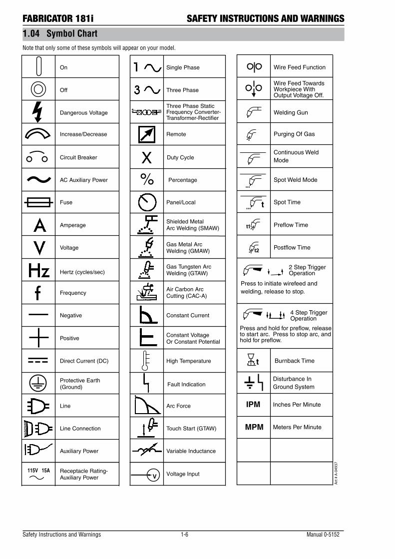
FABRICATOR 181i SAFETY INSTRUCTIONS AND WARNINGS1.04 Symbol ChartNote that only some of these symbols will appear on your model.
Gas Tungsten Arc Welding (GTAW)
Air Carbon Arc Cutting (CAC-A)
Constant Current
Constant Voltage Or Constant Potential
High Temperature
Fault Indication
Arc Force
Touch Start (GTAW)
Variable Inductance
Voltage Input
Single Phase
Three Phase
Three Phase Static Frequency Converter-Transformer-Rectifier
Dangerous Voltage
Off
On
Panel/Local
Shielded Metal Arc Welding (SMAW)
Gas Metal Arc Welding (GMAW)
Increase/Decrease
Circuit Breaker
AC Auxiliary Power
Remote
Duty Cycle
Percentage
Amperage
Voltage
Hertz (cycles/sec)
Frequency
Negative
Positive
Direct Current (DC)
Protective Earth (Ground)
Line
Line Connection
Auxiliary Power
Receptacle Rating-Auxiliary Power
Art
# A
-049
37
115V 15A
t
t1
t2
%X
IPM
MPM
t
V
Fuse
Wire Feed Function
Wire Feed Towards Workpiece With Output Voltage Off.
Preflow Time
Postflow Time
Spot Time
Spot Weld Mode
Continuous WeldMode
Press to initiate wirefeed and welding, release to stop.
Purging Of Gas
Inches Per Minute
Meters Per Minute
Disturbance InGround System
Welding Gun
Burnback Time
Press and hold for preflow, releaseto start arc. Press to stop arc, andhold for preflow.
4 Step TriggerOperation
2 Step TriggerOperation
SAFETY INSTRUCTIONS AND WARNINGS FABRICATOR 181i
Manual 0-5152 1-7 Safety Instructions and Warnings
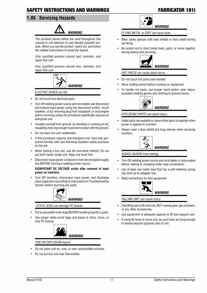
1.05 Servicing Hazards
! WARNING
The symbols shown below are used throughout this manual to call attention to and identify possible haz-ards. When you see the symbol, watch out, and follow the related instructions to avoid the hazard.
Only qualified persons should test, maintain, and repair this unit.
Only qualified persons should test, maintain, and repair this unit.
WARNING
ELECTRIC SHOCK can kill.
• Donottouchliveelectricalparts.
• TurnOffweldingpowersourceandwirefeederanddisconnectand lockout input power using line disconnect switch, circuit breakers, or by removing plug from receptacle, or stop engine before servicing unless the procedure specifically requires an energized unit.
• Insulateyourselffromgroundbystandingorworkingondryinsulating mats big enough to prevent contact with the ground.
• Donotleaveliveunitunattended.
• Ifthisprocedurerequiresandenergizedunit,haveonlyper-sonnel familiar with and following standard safety practices do the job.
• Whentestingaliveunit,usetheone-handmethod.Donotput both hands inside unit. Keep one hand free.
• Disconnectinputpowerconductorsfromde-energizedsupplyline BEFORE moving a welding power source.
SIGNIFICANT DC VOLTAGE exists after removal of input power on inverters.
• TurnOff inverters, disconnect input power, and dischargeinput capacitors according to instructions in Troubleshooting Section before touching any parts.
WARNING
STATIC (ESD) can damage PC boards.
• PutongroundedwriststrapBEFOREhandlingboardsorparts.
• Useproperstatic-proofbagsandboxestostore,move,orship PC boards.
WARNING
FIRE OR EXPLOSION hazard.
• Donotplaceuniton,over,ornearcombustiblesurfaces.
• Donotserviceunitnearflammables.
WARNING
FLYING METAL or DIRT can injure eyes.
• Wearsafetyglasseswithsideshieldsorfaceshieldduringservicing.
• Becarefulnottoshortmetaltools,parts,orwirestogetherduring testing and servicing.
WARNING
HOT PARTS can cause sever burns.
• Donottouchhotpartsbarehanded.
• Allowcoolingperiodbeforeworkingonequipment.
• To handle not parts, use proper tools and/orwear heavy,insulated welding gloves and clothing to prevent burns.
WARNING
EXPLODING PARTS can cause injury.
• Failedpartscanexplodeorcauseotherpartstoexplodewhenpower is applied to inverters.
• Alwayswearafaceshieldandlongsleeveswhenservicinginverters.
WARNING
SHOCK HAZARD from testing.
• TurnOffweldingpowersourceandwirefeederorstopenginebefore making or changing meter lead connections.
• Useatleastonemeterleadthathasaself-retainingspringclip such as an alligator clip.
• Readinstructionsfortestequipment.
WARNING
FALLING UNIT can cause injury.
• Useliftingeyetoliftunitonly,NOTrunninggear,gascylinders,or any other accessories.
• Useequipmentofadequatecapacitytoliftandsupportunit.
• Ifusingliftforkstomoveunit,besureforksarelongenoughto extend beyond opposite side of unit.
Safety Instructions and Warnings 1-8 Manual 0-5152
FABRICATOR 181i SAFETY INSTRUCTIONS AND WARNINGS
WARNING
MOVING PARTS can cause injury,
• Keepawayfrommovingpartssuchasfans.
• Keepawayfrompinchpointssuchasdriverolls.
• Haveonlyqualifiedpersonsremovedoors,panels,covers,or guards for maintenance as necessary.
• Keephands,hair,looseclothing,andtoolsawayfrommovingparts.
• Reinstalldoors,panels,covers,orguardswhenmaintenanceis finished and before reconnecting input power.
WARNING
MAGNETIC FIELDS can affect Implanted Medical Devices.
• WearersofPacemakersandotherImplantedMedicalDevicesshould keep away from servicing areas until consulting their doctor and the device manufacturer.
WARNING
OVERUSE can cause OVERHEATING.
• Allowcoolingperiod;followrateddutycycle.
• Reducecurrentorreducedutycyclebeforestartingtoweldagain.
• Donotblockorfilterairflowtounit.
WARNING
H.F. RADIATION can cause interference.
• High-frequency (H.F.) can interferewith radio navigation,safety services, computers, and communications equipment.
• Haveonlyqualifiedpersonsfamiliarwithelectronicequipmentinstall, test, and service H.F. producing units.
• The user is responsible for having a qualified electricianpromptly correct any interference problem resulting from the installation.
• If notified by the FCC about interference, stop using theequipment at once.
• Havetheinstallationregularlycheckedandmaintained.
• Keephigh-frequencysourcedoorsandpanelstightlyshut,keep spark gaps at correct setting, and use grounding and shielding to minimize the possibility of interference.
! WARNING
READ INSTRUCTIONS.
• UseTestingBooklet(PartNo.150853)whenservicingthisunit.
• ConsulttheOwner’sManualforweldingsafetyprecautions.
• Useonlygenuinereplacementpartsfromthemanufacturer.
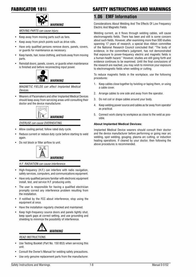
1.06 EMF InformationConsiderations About Welding And The Effects Of Low Frequency Electric And Magnetic Fields
Welding current, as it flows through welding cables, will cause electromagnetic fields. There has been and still is some concern about such fields. However, after examining more than 500 studies spanning 17 years of research, a special blue ribbon committee of the National Research Council concluded that: “The body of evidence, in the committee’s judgment, has not demonstrated that exposure to power-frequency electric and magnetic fields is a human-health hazard.” However, studies are still going forth and evidence continues to be examined. Until the final conclusions of the research are reached, you may wish to minimize your exposure to electromagnetic fields when welding or cutting.
To reduce magnetic fields in the workplace, use the following procedures:
1. Keep cables close together by twisting or taping them, or using a cable cover.
2. Arrange cables to one side and away from the operator.
3. Do not coil or drape cables around your body.
4. Keep welding power source and cables as far away from operator as practical.
5. Connect work clamp to workpiece as close to the weld as pos-sible.
About Implanted Medical Devices:
Implanted Medical Device wearers should consult their doctor and the device manufacturer before performing or going near arc welding, spot welding, gouging, plasma arc cutting, or induction heating operations. If cleared by your doctor, then following the above procedures is recommended.
INTRODUCTION FABRICATOR 181i
Manual 0-5152 2-1 Introduction
SECTION 2: INTRODUCTION
2.01 How to Use This ManualThis Manual usually applies to the part numbers listed on page i. To ensure safe operation, read the entire manual, including the chapter on safety instructions and warnings. Throughout this manual, the word WARNING, CAUTION and NOTE may appear. Pay particular attention to the information provided under these headings. These special annotations are easily recognized as follows:
! WARNING
Gives information regarding possible per-sonal injury. Warnings will be enclosed in a box such as this.
CAUTIONRefers to possible equipment damage. Cau-tions will be shown in bold type.
NOTEOffers helpful information concerning certain operating procedures. Notes will be shown in italics
You will also notice icons from the safety section ap-pearing throughout the manual. These are to advise you of specific types of hazards or cautions related to the portion of information that follows. Some may have multiple hazards that apply and would look something like this:
2.02 Equipment IdentificationThe unit’s identification number (specification or part number), model, and serial number usually appear on a nameplate attached to the machine. Equipment which does not have a nameplate attached to the machine is identified only by the specification or part number printed on the shipping container. Record these num-bers for future reference.
2.03 Receipt of EquipmentWhen you receive the equipment, check it against the invoice to make sure it is complete and inspect the equipment for possible damage due to shipping. If there is any damage, notify the carrier immediately to file a claim. Furnish complete information concerning damage claims or shipping errors to the location in your area listed in the inside back cover of this manual. Include all equipment identification numbers as described above along with a full description of the parts in error.
2.04 DescriptionThe Thermal Arc Fabricator 181i is a self contained sin-gle phase multi process welding inverter that is capable of performing GMAW/FCAW (MIG), MMA (Stick) and GTAW (Lift TIG) welding processes. The unit is equipped with an integrated wire feed unit, digital voltage and amperage meters, and a host of other features in order to fully satisfy the broad operating needs of the modern welding professional. The unit is also fully compliant to European Standard EN 60974-1.The Fabricator 181i MIG provides excellent welding performance across a broad range of applications when used with the correct welding consumables and proce-dures. The following instructions detail how to correctly and safely set up the machine and give guidelines on gaining the best efficiency and quality from the Power Source. Please read these instructions thoroughly be-fore using the unit.
2.05 Transportation Methods
!Disconnect input power con-
ductors from de-energized supply line before moving the welding power source.Lift unit with handle on top of case. Use handcart or similar device of adequate capacity. If using a fork lift vehicle, secure the unit on a proper skid before trans-porting.

FABRICATOR 181i INTRODUCTION
Introduction 2-2 Manual 0-5152
2.06 Packaged ItemsFabricator 181i Plant (Part No. W1003186)
• Fabricator 181i Inverter Power Source
• TwecoWeldSkill180AMIGTorch
• Feedrolls:0.6/0.8mmVGroove(fitted)
• ElectrodeHolderwith4mLead
• WorkClampwith4mLead
• ShieldingGasHoseAssembly
• ShoulderStrap
• OperatingManual
Manual 0-5152 3-1 Safety and Installation
SAFETY AND INSTALLATION FABRICATOR 181i
3.01 Duty Cycle
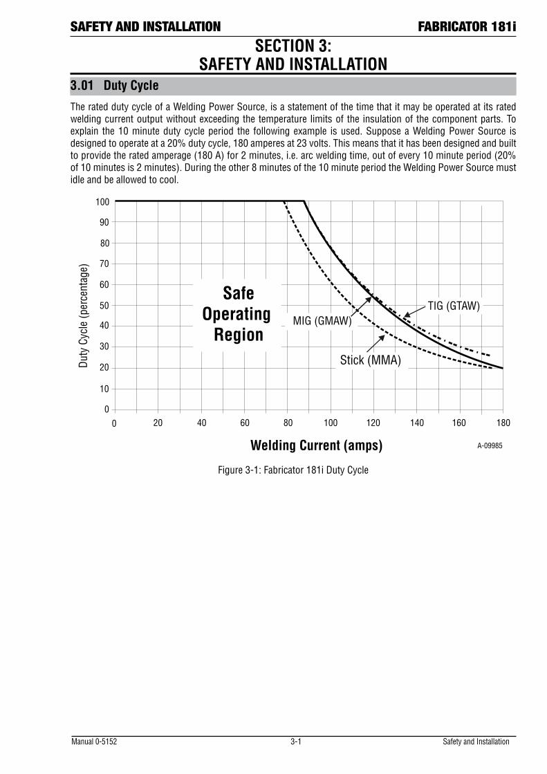
The rated duty cycle of a Welding Power Source, is a statement of the time that it may be operated at its rated welding current output without exceeding the temperature limits of the insulation of the component parts. To explain the 10 minute duty cycle period the following example is used. Suppose a Welding Power Source is designed to operate at a 20% duty cycle, 180 amperes at 23 volts. This means that it has been designed and built to provide the rated amperage (180 A) for 2 minutes, i.e. arc welding time, out of every 10 minute period (20% of 10 minutes is 2 minutes). During the other 8 minutes of the 10 minute period the Welding Power Source must idle and be allowed to cool.
A-09985
Duty
Cyc
le (p
erce
ntag
e)
SafeOperating
Region
0 20 40 60
80
100
120 140 160 180
30
50
70
90
40
60
20
10
80 1000
Welding Current (amps)
Stick (MMA)
TIG (GTAW)MIG (GMAW)
Figure 3-1: Fabricator 181i Duty Cycle
SECTION 3: SAFETY AND INSTALLATION
Safety and Installation 3-2 Manual 0-5152
FABRICATOR 181i SAFETY AND INSTALLATION
3.03 Environment
These units are designed for use in environments with increased hazard of electric shock.
A. Examples of environments with increased hazard of electric shock are:
1. In locations in which freedom of movement is restricted, so that the operator is forced to perform the work in a cramped (kneeling, sitting or lying) position with physical contact with conductive parts.
2. In locations which are fully or partially limited by conductive elements, and in which there is a high risk of unavoidable or accidental contact by the operator.
3. In wet or damp hot locations where humidity or perspiration considerable reduces the skin resistance of the human body and the insulation properties of accessories.
B. Environments with increased hazard of electric shock do not include places where electrically conductive parts in the near vicinity of the operator, which can cause increased hazard, have been insulated.
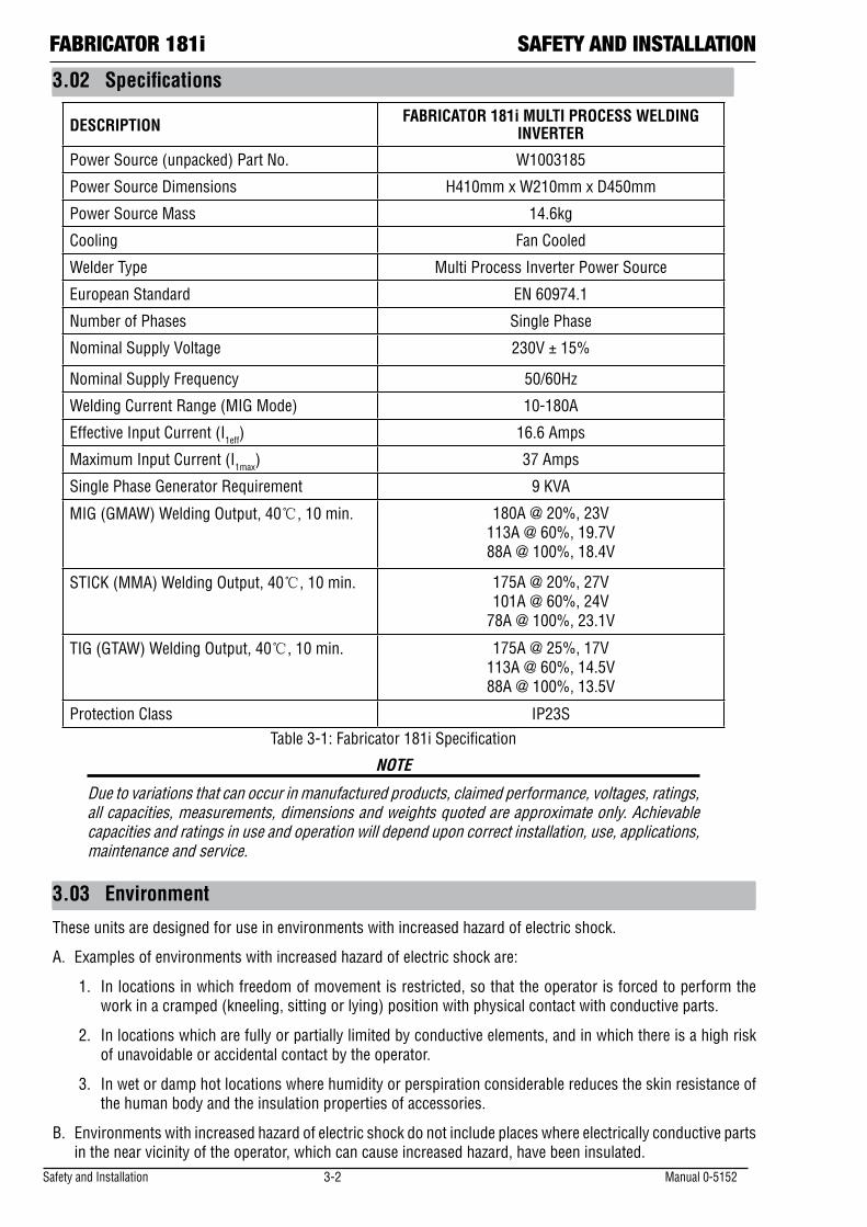
3.02 Specifications
DESCRIPTION FABRICATOR 181i MULTI PROCESS WELDING INVERTER
Power Source (unpacked) Part No. W1003185
Power Source Dimensions H410mm x W210mm x D450mm
Power Source Mass 14.6kg
Cooling Fan Cooled
Welder Type Multi Process Inverter Power Source
European Standard EN 60974.1
Number of Phases Single Phase
Nominal Supply Voltage 230V ± 15%
Nominal Supply Frequency 50/60Hz
Welding Current Range (MIG Mode) 10-180A
Effective Input Current (I1eff) 16.6 Amps
Maximum Input Current (I1max) 37 Amps
Single Phase Generator Requirement 9 KVA
MIG (GMAW) Welding Output, 40, 10 min. 180A @ 20%, 23V 113A @ 60%, 19.7V 88A @ 100%, 18.4V
STICK (MMA) Welding Output, 40, 10 min. 175A @ 20%, 27V 101A @ 60%, 24V
78A @ 100%, 23.1V
TIG (GTAW) Welding Output, 40, 10 min. 175A @ 25%, 17V 113A @ 60%, 14.5V 88A @ 100%, 13.5V
Protection Class IP23STable 3-1: Fabricator 181i Specification
NOTE
Due to variations that can occur in manufactured products, claimed performance, voltages, ratings, all capacities, measurements, dimensions and weights quoted are approximate only. Achievable capacities and ratings in use and operation will depend upon correct installation, use, applications, maintenance and service.
Manual 0-5152 3-3 Safety and Installation
SAFETY AND INSTALLATION FABRICATOR 181i
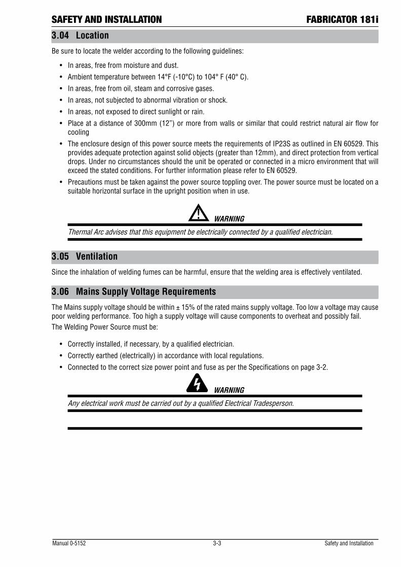
3.04 Location
Be sure to locate the welder according to the following guidelines:
• Inareas,freefrommoistureanddust.
• Ambienttemperaturebetween14°F(-10°C)to104°F(40°C).
• Inareas,freefromoil,steamandcorrosivegases.
• Inareas,notsubjectedtoabnormalvibrationorshock.
• Inareas,notexposedtodirectsunlightorrain.
• Placeatadistanceof300mm(12”)ormorefromwallsorsimilarthatcouldrestrictnaturalairflowforcooling
• TheenclosuredesignofthispowersourcemeetstherequirementsofIP23SasoutlinedinEN60529.Thisprovides adequate protection against solid objects (greater than 12mm), and direct protection from vertical drops. Under no circumstances should the unit be operated or connected in a micro environment that will exceed the stated conditions. For further information please refer to EN 60529.
• Precautionsmustbetakenagainstthepowersourcetopplingover.Thepowersourcemustbelocatedonasuitable horizontal surface in the upright position when in use.
! WARNING
Thermal Arc advises that this equipment be electrically connected by a qualified electrician.
3.05 Ventilation
Since the inhalation of welding fumes can be harmful, ensure that the welding area is effectively ventilated.
3.06 Mains Supply Voltage Requirements
The Mains supply voltage should be within ± 15% of the rated mains supply voltage. Too low a voltage may cause poor welding performance. Too high a supply voltage will cause components to overheat and possibly fail.The Welding Power Source must be:
• Correctlyinstalled,ifnecessary,byaqualifiedelectrician.
• Correctlyearthed(electrically)inaccordancewithlocalregulations.
• ConnectedtothecorrectsizepowerpointandfuseaspertheSpecificationsonpage3-2.
WARNING
Any electrical work must be carried out by a qualified Electrical Tradesperson.
Safety and Installation 3-4 Manual 0-5152
FABRICATOR 181i SAFETY AND INSTALLATION
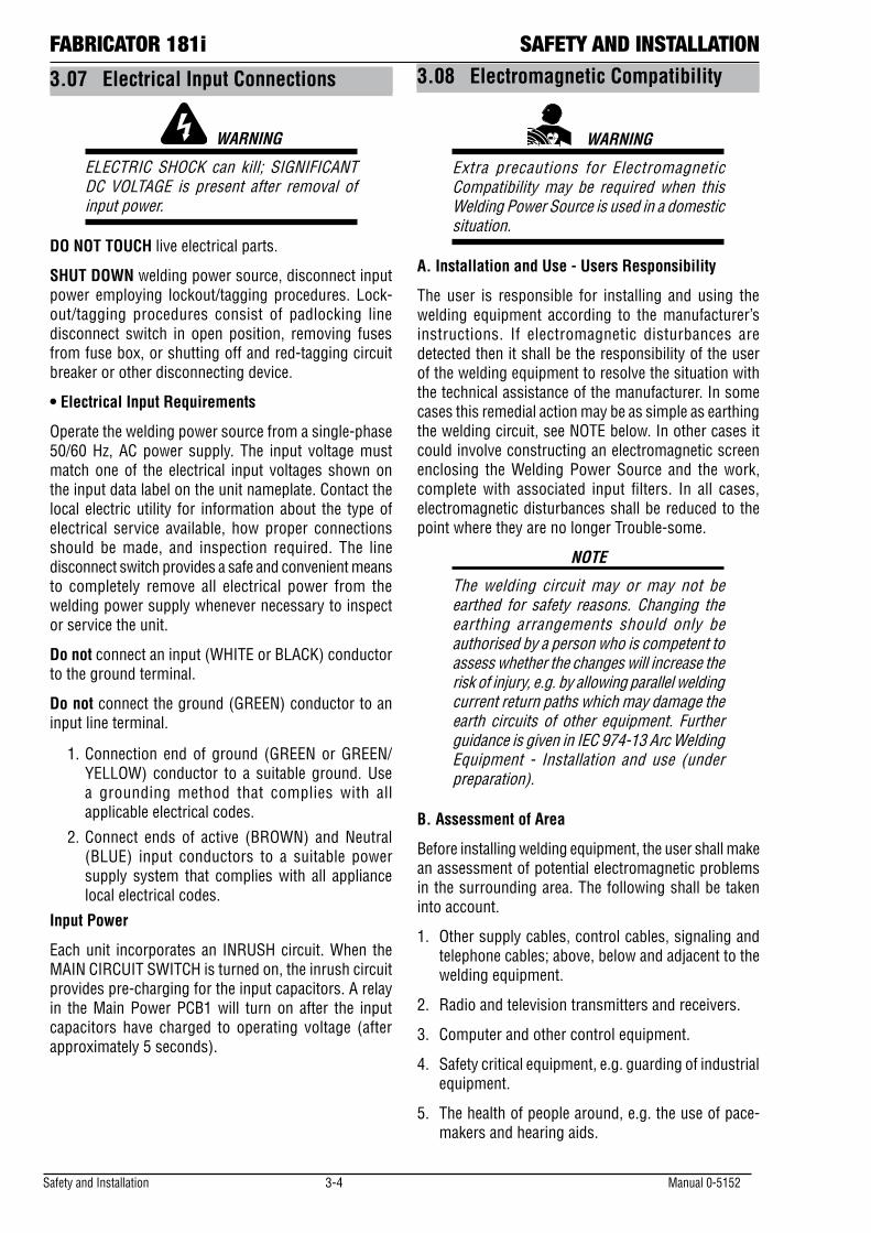
3.07 Electrical Input Connections
WARNING
ELECTRIC SHOCK can kill; SIGNIFICANT DC VOLTAGE is present after removal of input power.
DO NOT TOUCH live electrical parts.
SHUT DOWN welding power source, disconnect input power employing lockout/tagging procedures. Lock-out/tagging procedures consist of padlocking line disconnect switch in open position, removing fuses from fuse box, or shutting off and red-tagging circuit breaker or other disconnecting device.
• Electrical Input Requirements
Operate the welding power source from a single-phase 50/60 Hz, AC power supply. The input voltage must match one of the electrical input voltages shown on the input data label on the unit nameplate. Contact the local electric utility for information about the type of electrical service available, how proper connections should be made, and inspection required. The line disconnect switch provides a safe and convenient means to completely remove all electrical power from the welding power supply whenever necessary to inspect or service the unit.
Do not connect an input (WHITE or BLACK) conductor to the ground terminal.
Do not connect the ground (GREEN) conductor to an input line terminal.
1. Connection end of ground (GREEN or GREEN/YELLOW) conductor to a suitable ground. Use a grounding method that complies with all applicable electrical codes.
2. Connect ends of active (BROWN) and Neutral (BLUE) input conductors to a suitable power supply system that complies with all appliance local electrical codes.
Input Power
Each unit incorporates an INRUSH circuit. When the MAIN CIRCUIT SWITCH is turned on, the inrush circuit provides pre-charging for the input capacitors. A relay in the Main Power PCB1 will turn on after the input capacitors have charged to operating voltage (after approximately 5 seconds).
3.08 Electromagnetic Compatibility
WARNING
Extra precautions for Electromagnetic Compatibility may be required when this Welding Power Source is used in a domestic situation.
A. Installation and Use - Users Responsibility
The user is responsible for installing and using the welding equipment according to the manufacturer’s instructions. If electromagnetic disturbances are detected then it shall be the responsibility of the user of the welding equipment to resolve the situation with the technical assistance of the manufacturer. In some cases this remedial action may be as simple as earthing the welding circuit, see NOTE below. In other cases it could involve constructing an electromagnetic screen enclosing the Welding Power Source and the work, complete with associated input filters. In all cases, electromagnetic disturbances shall be reduced to the point where they are no longer Trouble-some.
NOTE
The welding circuit may or may not be earthed for safety reasons. Changing the earthing arrangements should only be authorised by a person who is competent to assess whether the changes will increase the risk of injury, e.g. by allowing parallel welding current return paths which may damage the earth circuits of other equipment. Further guidance is given in IEC 974-13 Arc Welding Equipment - Installation and use (under preparation).
B. Assessment of Area
Before installing welding equipment, the user shall make an assessment of potential electromagnetic problems in the surrounding area. The following shall be taken into account.
1. Other supply cables, control cables, signaling and telephone cables; above, below and adjacent to the welding equipment.
2. Radio and television transmitters and receivers.
3. Computer and other control equipment.
4. Safety critical equipment, e.g. guarding of industrial equipment.
5. The health of people around, e.g. the use of pace-makers and hearing aids.
Manual 0-5152 3-5 Safety and Installation
SAFETY AND INSTALLATION FABRICATOR 181i6. Equipment used for calibration and measurement.
7. The time of day that welding or other activities are to be carried out.
8. The immunity of other equipment in the environment: the user shall ensure that other equipment being used in the environment is compatible: this may require additional protection measures.
The size of the surrounding area to be considered will depend on the structure of the building and other activities that are taking place. The surrounding area may extend beyond the boundaries of the premises.
C. Methods of Reducing Electromagnetic Emissions
1. Mains Supply
Welding equipment should be connected to the mains supply according to the manufacturer’s recommendations. If interference occurs, it may be necessary to take additional precautions such as filtering of the mains supply. Consideration should be given to shielding the supply cable of permanently installed welding equipment in metallic conduit or equivalent. Shielding should be electrically continuous throughout its length. The shielding should be connected to the Welding Power Source so that good electrical contact is maintained between the conduit and the Welding Power Source enclosure.
2. Maintenance of Welding Equipment
The welding equipment should be routinely maintained according to the manufacturer’s recommendations. All access and service doors and covers should be closed and properly fastened when the welding equipment is in operation. The welding equipment should not be modified in any way except for those changes and adjustments covered in the manufacturer’s instructions. In particular, the spark gaps of arc striking and stabilizing devices should be adjusted and maintained according to the manufacturer’s recommendation
3. Welding Cables
The welding cables should be kept as short as possible and should be positioned close together, running at or close to the floor level.
4. Equipotential Bonding
Bonding of all metallic components in the welding installation and adjacent to it should be considered. However, metallic components bonded to the work piece will increase the risk that the operator could receive a shock by touching the metallic components and the electrode at the same time. The operator should be insulated from all such bonded metallic components.
5. Earthing of the Work Piece
Where the work piece is not bonded to earth for electrical safety, nor connected to earth because of its size and position, e.g. ship’s hull or building steelwork, a connection bonding the work piece to earth may reduce emissions in some, but not all instances. Care should be taken to prevent the earthing of the work piece increasing the risk of injury to users, or damage to other electrical equipment. Where necessary, the connection of the work piece to earth should be made by direct connection to the work piece, but in some countries where direct connection is not permitted, the bonding should be achieved by suitable capacitance, selected according to national regulations.
6. Screening and Shielding
Selective screening and shielding of other cables and equipment in the surrounding area may alleviate problems of interference. Screening the entire welding installation may be considered for special applications.
Safety and Installation 3-6 Manual 0-5152
FABRICATOR 181i SAFETY AND INSTALLATION
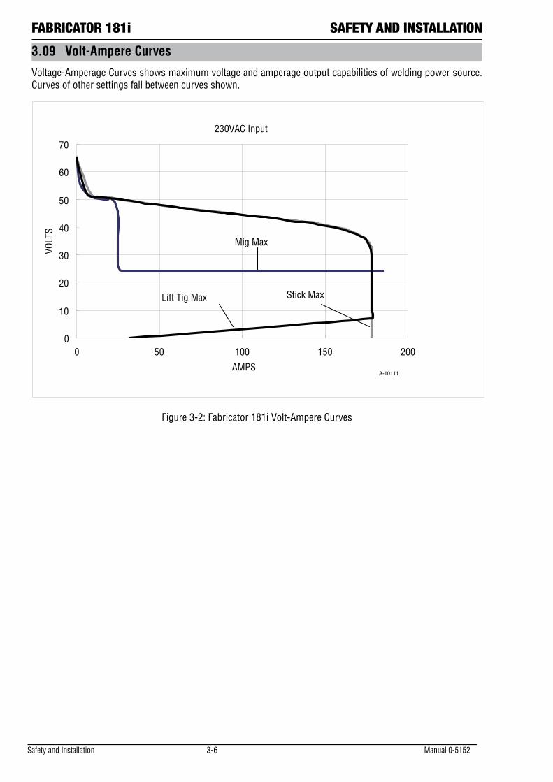
3.09 Volt-Ampere Curves
Voltage-Amperage Curves shows maximum voltage and amperage output capabilities of welding power source. Curves of other settings fall between curves shown.
230VAC Input
0
10
20
30
40
50
60
70
0 50 100 150 200
AMPS
VOLT
S
Lift Tig Max
Mig Max
Stick Max
A-10111
Figure 3-2: Fabricator 181i Volt-Ampere Curves
OPERATION FABRICATOR 181i
Manual 0-5152 4-1 Operation
SECTION 4: OPERATION
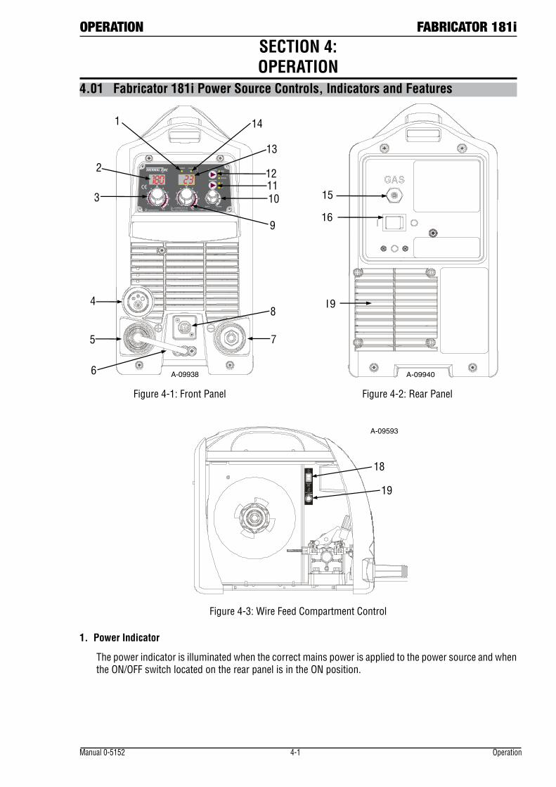
4.01 Fabricator 181i Power Source Controls, Indicators and Features
MIG
LIFT TIG
STICK
4T
2T
POWER
SOFT
A V
WIRESPEED
HARD
FAULT
DOWNSLOPE (S)10 10
2 2
4 4
7 7
9 91 1
3 3
6 6
8 8
ARC FORCE (%) INDUCTANCE
2
4 6
8
1
2
3
4
5
6
7
8
9
1011
12
13
14
A-09938 A-09940
16
19
15
Figure 4-1: Front Panel Figure 4-2: Rear Panel
18
19
A-09593
Figure 4-3: Wire Feed Compartment Control
1. Power Indicator
The power indicator is illuminated when the correct mains power is applied to the power source and when the ON/OFF switch located on the rear panel is in the ON position.
FABRICATOR 181i OPERATION
Operation 4-2 Manual 0-5152
2. Digital Amps Meter
The digital amperage meter is used to display both the pre-set current (Stick and TIG modes only) and actual output current (all modes) of the power source.
At times of non-welding, the amperage meter will display a pre-set (preview) value in both MMA (Stick) and GTAW (TIG) modes. This value can be adjusted by varying the amperage potentiometer (item 4). Note that in GMAW/FCAW (MIG) mode, the amperage meter will not preview welding current and will display zero.
When welding, the amperage meter will display actual welding current in all modes.
At the completion of welding, the amperage meter will hold the last recorded amperage value for a period of approximately 10 seconds in all modes. The amperage meter will hold the value until; (1) any of the front panel controls are adjusted in which case the unit will revert to preview mode, (2) welding is recommenced, in which case actual welding amperage will be displayed, or (3) a period of 10 seconds elapses following the completion of welding in which case the unit will return to preview mode.
3. Amperage Control (Wirespeed)
The amperage control knob adjusts the amount of welding current delivered by the power source. In MMA (stick) and GTAW (TIG) modes, the amperage control knob directly adjusts the power inverter to deliver the desired level of output current. In GMAW/FCAW modes (MIG), the amperage knob adjusts the speed of the wire feed motor (which in turn adjusts the output current by varying the amount of MIG wire delivered to the welding arc). The optimum wire speed required will dependent on the type of welding application. The setup chart on the inside of the wire feed compartment door provides a brief summary of the required output settings for a basic range of MIG welding applications.
4. MIG Torch Adaptor (Euro Style)
The MIG torch adaptor is the connection point for the MIG welding torch. Connect the torch by pushing the torch connector into the brass torch adaptor firmly and screwing the plastic torch nut clockwise to secure in position. To remove the MIG Torch simply reverse these directions.
5. Positive Welding Output Terminal
The positive welding terminal is used to connect the welding output of the power source to the appropriate welding accessory such as the MIG torch (via the MIG torch polarity lead), electrode holder lead or work lead. Positive welding current flows from the power source via this heavy duty bayonet type terminal. It is essential, however, that the male plug is inserted and turned securely to achieve a sound electrical connection.
CAUTION
Loose welding terminal connections can cause overheating and result in the male plug being fused in the bayonet terminal.
6. MIG Torch Polarity Lead
The polarity lead is used to connect the MIG torch to the appropriate positive or negative output terminal (allowing polarity reversal for different welding applications). In general, the polarity lead should be connected in to the positive welding terminal (+) when using steel, stainless steel or aluminium electrode wire. When using gasless wire, the polarity lead is generally connected to the negative welding terminal (-). If in doubt, consult the manufacturer of the electrode wire for the correct polarity. It is essential, however, that the male plug is inserted and turned securely to achieve a sound electrical connection.
CAUTION
Loose welding terminal connections can cause overheating and result in the male plug being fused in the bayonet terminal.
OPERATION FABRICATOR 181i
Manual 0-5152 4-3 Operation
7. Negative Welding Output Terminal
The negative welding terminal is used to connect the welding output of the power source to the appropriate welding accessory such as the MIG torch (via the MIG torch polarity lead), TIG torch or work lead. Negative welding current flows to the power source via this heavy duty bayonet type terminal. It is essential, however, that the male plug is inserted and turned securely to achieve a sound electrical connection.
CAUTION
Loose welding terminal connections can cause overheating and result in the male plug being fused in the bayonet terminal.
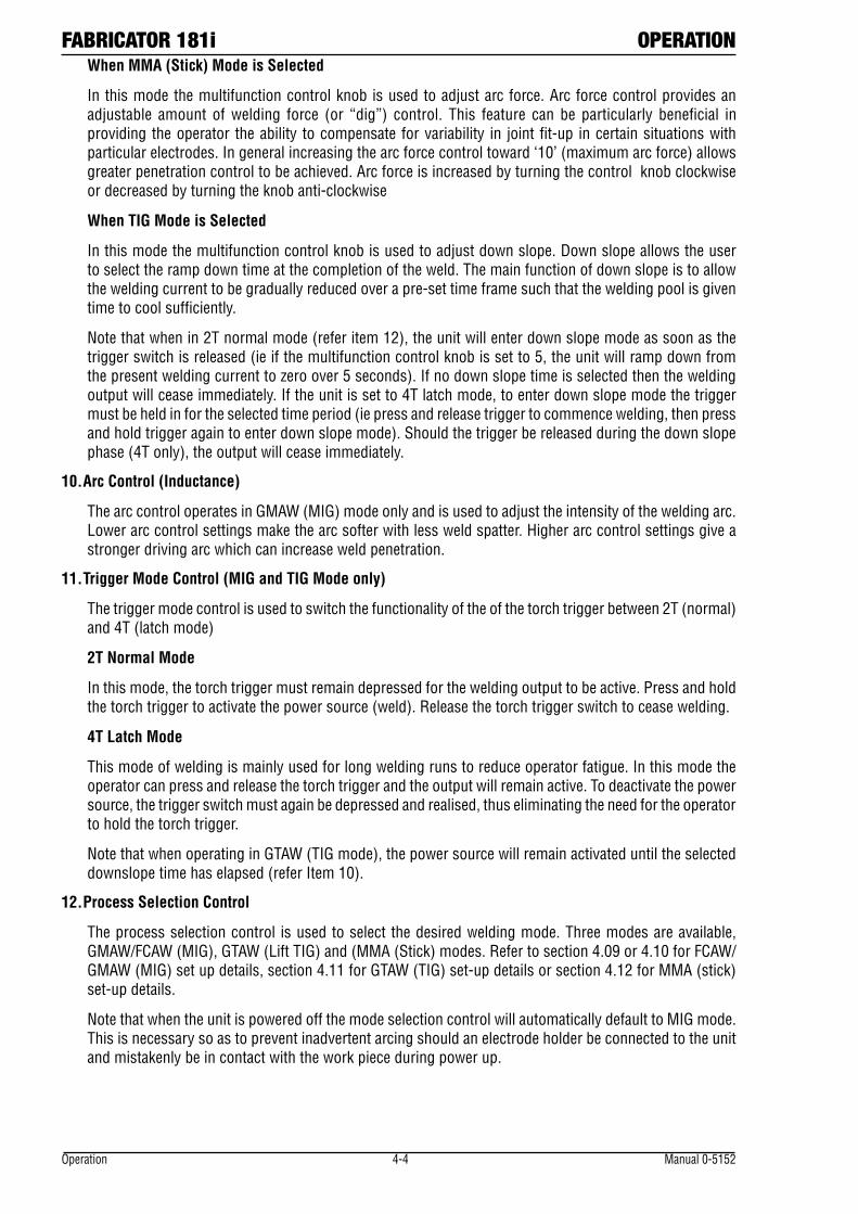
8. Remote Control Socket
The 8 pin Remote Control Socket is used to connect remote control devices to the welding power source. To make connections, align keyway, insert plug, and rotate threaded collar fully clockwise.
2 1
8 7 6
3 4 5
Trigger Switch
Remote Wirespeed in GMAW mode
Remote Amps in GTAW mode
Remote Volts in GMAW Mode
1 2
3 4
5
6
7 8
W V
A-09594_AC
Figure 4-4: Remote Control Socket
Socket Pin Function
1 Not connected
2 Trigger Switch Input
3 Trigger Switch Input
4 Not connected
5 5k ohm (maximum) connection to 5k ohm remote control potentiometer.
6 Zero ohm (minimum) connection to 5k ohm remote control potentiometer.
7 Wiper arm connection to 5k ohm remote control Wirespeed GMAW (MIG) mode potentiometer. Wiper arm connection to 5k ohm remote control Amps GTAW (TIG) mode potentiometer.
8 Wiper arm connection to 5k ohm remote control Volts GMAW (MIG) mode potentiometer.
Table 4-1
Note that the remote local switch (item 18) located in the wirefeed compartment should be set to remote for the amperage/voltage controls to be operative.
9. Multifunction Control - Voltage, Down Slope & Arc Force
The multifunction control knob is used to adjust three main parameters depending on the welding mode selected.
When GMAW/FCAW (MIG) Mode is Selected
In this mode the control knob is used to adjust the output voltage of the unit. The welding voltage is increased by turning the knob clockwise or decreased by turning the knob anti-clockwise. The optimum voltage level required will dependent on the type of welding application. The setup chart on the inside of the wire feed compartment door provides a brief summary of the required output settings for a basic range of MIG welding applications.
FABRICATOR 181i OPERATION
Operation 4-4 Manual 0-5152
When MMA (Stick) Mode is Selected
In this mode the multifunction control knob is used to adjust arc force. Arc force control provides an adjustable amount of welding force (or “dig”) control. This feature can be particularly beneficial in providing the operator the ability to compensate for variability in joint fit-up in certain situations with particular electrodes. In general increasing the arc force control toward ‘10’ (maximum arc force) allows greater penetration control to be achieved. Arc force is increased by turning the control knob clockwise or decreased by turning the knob anti-clockwise
When TIG Mode is Selected
In this mode the multifunction control knob is used to adjust down slope. Down slope allows the user to select the ramp down time at the completion of the weld. The main function of down slope is to allow the welding current to be gradually reduced over a pre-set time frame such that the welding pool is given time to cool sufficiently.
Note that when in 2T normal mode (refer item 12), the unit will enter down slope mode as soon as the trigger switch is released (ie if the multifunction control knob is set to 5, the unit will ramp down from the present welding current to zero over 5 seconds). If no down slope time is selected then the welding output will cease immediately. If the unit is set to 4T latch mode, to enter down slope mode the trigger must be held in for the selected time period (ie press and release trigger to commence welding, then press and hold trigger again to enter down slope mode). Should the trigger be released during the down slope phase (4T only), the output will cease immediately.
10. Arc Control (Inductance)
The arc control operates in GMAW (MIG) mode only and is used to adjust the intensity of the welding arc. Lower arc control settings make the arc softer with less weld spatter. Higher arc control settings give a stronger driving arc which can increase weld penetration.
11. Trigger Mode Control (MIG and TIG Mode only)
The trigger mode control is used to switch the functionality of the of the torch trigger between 2T (normal) and 4T (latch mode)
2T Normal Mode
In this mode, the torch trigger must remain depressed for the welding output to be active. Press and hold the torch trigger to activate the power source (weld). Release the torch trigger switch to cease welding.
4T Latch Mode
This mode of welding is mainly used for long welding runs to reduce operator fatigue. In this mode the operator can press and release the torch trigger and the output will remain active. To deactivate the power source, the trigger switch must again be depressed and realised, thus eliminating the need for the operator to hold the torch trigger.
Note that when operating in GTAW (TIG mode), the power source will remain activated until the selected downslope time has elapsed (refer Item 10).
12. Process Selection Control
The process selection control is used to select the desired welding mode. Three modes are available, GMAW/FCAW (MIG), GTAW (Lift TIG) and (MMA (Stick) modes. Refer to section 4.09 or 4.10 for FCAW/GMAW (MIG) set up details, section 4.11 for GTAW (TIG) set-up details or section 4.12 for MMA (stick) set-up details.
Note that when the unit is powered off the mode selection control will automatically default to MIG mode. This is necessary so as to prevent inadvertent arcing should an electrode holder be connected to the unit and mistakenly be in contact with the work piece during power up.
OPERATION FABRICATOR 181i
Manual 0-5152 4-5 Operation
13. Digital Voltage Meter
The digital voltage meter is used to display the both the pre-set voltage (MIG mode only) and actual output voltage (all modes) of the power source.
At times of non-welding, the voltage meter will display a pre-set (preview) value in GMAW/FCAW (MIG) modes. This value can be adjusted by varying the multifunction control knob (item 10). Note that in MMA (stick) and GTAW (TIG) modes, the voltage meter will not preview welding voltage and will display zero.When welding, the voltage meter will display actual welding current in all modes.
At the completion of welding, the digital voltage meter will hold the last recorded voltage value for a period of approximately 10 seconds in all modes. The voltage meter will hold the value until; (1) any of the front panel controls are adjusted in which case the unit will revert to preview mode, (2) welding is recommenced, in which case actual welding amperage will be displayed, or (3) a period of 10 seconds elapses following the completion of welding in which case the unit will return to preview mode.
14. Thermal Overload Indicator
This welding power source is protected by a self resetting thermostat. The indicator will illuminate if the duty cycle of the power source has been exceeded. Should the thermal overload indicator illuminate the output of the power source will be disabled. Once the power source cools down this light will go OFF and the over temperature condition will automatically reset. Note that the mains power switch should remain in the on position such that the fan continues to operate thus allowing the unit to cool sufficiently. Do not switch the unit off should a thermal overload condition be present.
15. Gas Inlet (MIG mode only)
The Gas Inlet connection is used to supply the appropriate MIG welding gas to the unit. Refer to section 4.09 or 4.10 for FCAW/GMAW (MIG) set up details.
! WARNING
Only Inert Shielding Gases specifically designed for welding applications should be used.
16. On / Off Switch
This switch is used to turn the unit on/off.
17. Local / Remote Switch (located in wirefeed compartment)
The remote / local switch is used only when a remote control device (such as a TIG torch with remote current control) is fitted to the unit via the remote control socket (item 9). When the local/remote switch is in the remote position, the unit will detect a remote device and work accordingly. When in the local mode, the unit will not detect the remote device and will operate from the power source controls only. Note that the trigger will operate at all times on the remote control socket irrespective of the position of the local remote switch (ie in both local and remote modes).
Should a remote device be connected and the remote/local switch set to remote, the maximum setting of the power source will be determined by the respective front panel control, irrespective of the remote control device setting. As an example, if the output current on the power source front panel is set to 50% and the remote control device is set to 100%, the maximum achievable output from the unit will be 50%. Should 100% output be required, the respective front panel control must be set to 100%, in which case the remote device will then be able to control between 0-100% output.
FABRICATOR 181i OPERATION
Operation 4-6 Manual 0-5152
18. Burnback Control (located in wirefeed compartment)
The burnback control is used to adjust the amount of MIG wire that protrudes from the MIG torch after the completion of MIG welding (commonly referred to as stick out). To decrease the burnback time (or lengthen the amount of wire protruding from the MIG torch at the completing of welding), turn the burnback control knob anti clockwise. To increase the burnback time (or shorten the amount of wire protruding from the torch at the completing of welding), turn the Burnback Control knob clockwise.
19. Fan on Demand
The Fabricator 181i is fitted with a fan on demand feature. Fan on demand automatically switches the cooling fan off when it is not required. This has two main advantages; (1) to minimize power consumption, and (2) to minimise the amount of contaminants such as dust that are drawn into the power source.
Note that the fan will only operate when required for cooling purposes and will automatically switch off when not required.
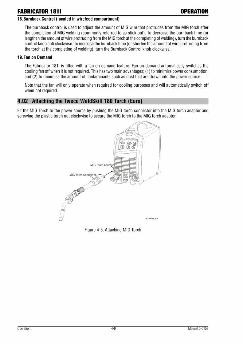
4.02 Attaching the Tweco WeldSkill 180 Torch (Euro)
Fit the MIG Torch to the power source by pushing the MIG torch connector into the MIG torch adaptor and screwing the plastic torch nut clockwise to secure the MIG torch to the MIG torch adaptor.
A-09521_AB
MIG Torch Adaptor
MIG Torch Connector
Figure 4-5: Attaching MIG Torch
OPERATION FABRICATOR 181i
Manual 0-5152 4-7 Operation
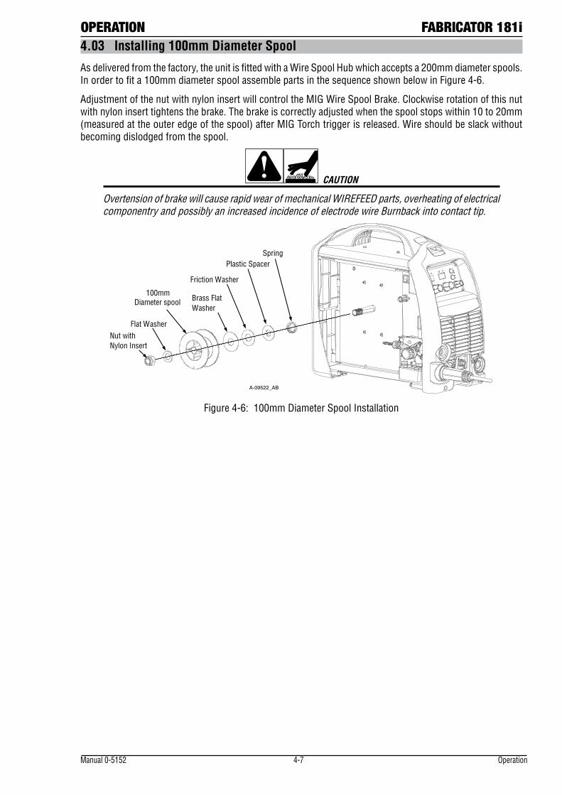
4.03 Installing 100mm Diameter Spool
As delivered from the factory, the unit is fitted with a Wire Spool Hub which accepts a 200mm diameter spools. In order to fit a 100mm diameter spool assemble parts in the sequence shown below in Figure 4-6.
Adjustment of the nut with nylon insert will control the MIG Wire Spool Brake. Clockwise rotation of this nut with nylon insert tightens the brake. The brake is correctly adjusted when the spool stops within 10 to 20mm (measured at the outer edge of the spool) after MIG Torch trigger is released. Wire should be slack without becoming dislodged from the spool.
CAUTION
Overtension of brake will cause rapid wear of mechanical WIREFEED parts, overheating of electrical componentry and possibly an increased incidence of electrode wire Burnback into contact tip.
A-09522_AB
Friction Washer
100mm Diameter spool
Nut with Nylon Insert
Spring Plastic Spacer
Brass Flat Washer
Flat Washer
Figure 4-6: 100mm Diameter Spool Installation
FABRICATOR 181i OPERATION
Operation 4-8 Manual 0-5152
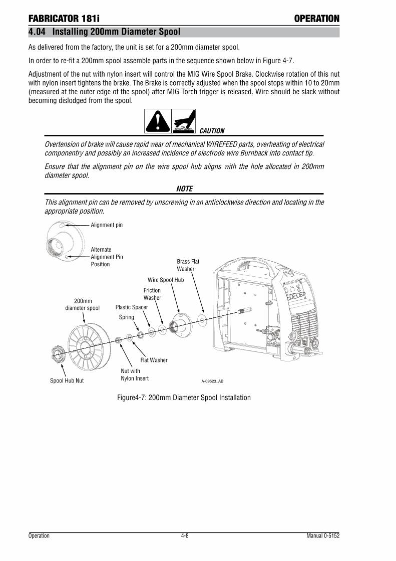
4.04 Installing 200mm Diameter Spool
As delivered from the factory, the unit is set for a 200mm diameter spool.
In order to re-fit a 200mm spool assemble parts in the sequence shown below in Figure 4-7.
Adjustment of the nut with nylon insert will control the MIG Wire Spool Brake. Clockwise rotation of this nut with nylon insert tightens the brake. The Brake is correctly adjusted when the spool stops within 10 to 20mm (measured at the outer edge of the spool) after MIG Torch trigger is released. Wire should be slack without becoming dislodged from the spool.
CAUTION
Overtension of brake will cause rapid wear of mechanical WIREFEED parts, overheating of electrical componentry and possibly an increased incidence of electrode wire Burnback into contact tip.
Ensure that the alignment pin on the wire spool hub aligns with the hole allocated in 200mm diameter spool.
NOTE
This alignment pin can be removed by unscrewing in an anticlockwise direction and locating in the appropriate position.
A-09523_AB
Spring
Nut with Nylon Insert
200mmdiameter spool
Spool Hub Nut
Alignment pin
Brass Flat Washer
Wire Spool Hub
Friction Washer
Plastic Spacer
Flat Washer
Alternate Alignment Pin Position
Figure4-7: 200mm Diameter Spool Installation
OPERATION FABRICATOR 181i
Manual 0-5152 4-9 Operation
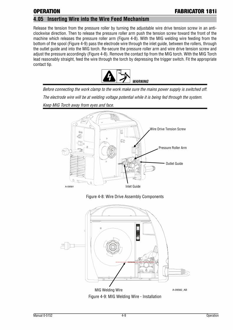
4.05 Inserting Wire into the Wire Feed Mechanism
Release the tension from the pressure roller by turning the adjustable wire drive tension screw in an anti-clockwise direction. Then to release the pressure roller arm push the tension screw toward the front of the machine which releases the pressure roller arm (Figure 4-8). With the MIG welding wire feeding from the bottom of the spool (Figure 4-9) pass the electrode wire through the inlet guide, between the rollers, through the outlet guide and into the MIG torch. Re-secure the pressure roller arm and wire drive tension screw and adjust the pressure accordingly (Figure 4-8). Remove the contact tip from the MIG torch. With the MIG Torch lead reasonably straight, feed the wire through the torch by depressing the trigger switch. Fit the appropriate contact tip.
WARNING
Before connecting the work clamp to the work make sure the mains power supply is switched off.
The electrode wire will be at welding voltage potential while it is being fed through the system.
Keep MIG Torch away from eyes and face.
A-09581
Outlet Guide
Inlet Guide
Wire Drive Tension Screw
Pressure Roller Arm
Figure 4-8: Wire Drive Assembly Components
MIG Welding Wire
A-09582_AB
Figure 4-9: MIG Welding Wire - Installation
FABRICATOR 181i OPERATION
Operation 4-10 Manual 0-5152
4.06 Feed Roller Pressure Adjustment
The pressure (top) roller applies pressure to the grooved feed roller via an adjustable pressure screw. These devices should be adjusted to a minimum pressure that will provide satisfactory WIREFEED without slippage. If slipping occurs, and inspection of the wire contact tip reveals no wear, distortion or burn back jam, the conduit liner should be checked for kinks and clogging by metal flakes and swarf. If it is not the cause of slipping, the feed roll pressure can be increased by rotating the pressure screw clockwise.
WARNING
Before changing the feed roller ensure that the mains supply to the power source is switched off.
CAUTION
The use of excessive pressure may cause rapid wear of the feed rollers, shafts and bearing.
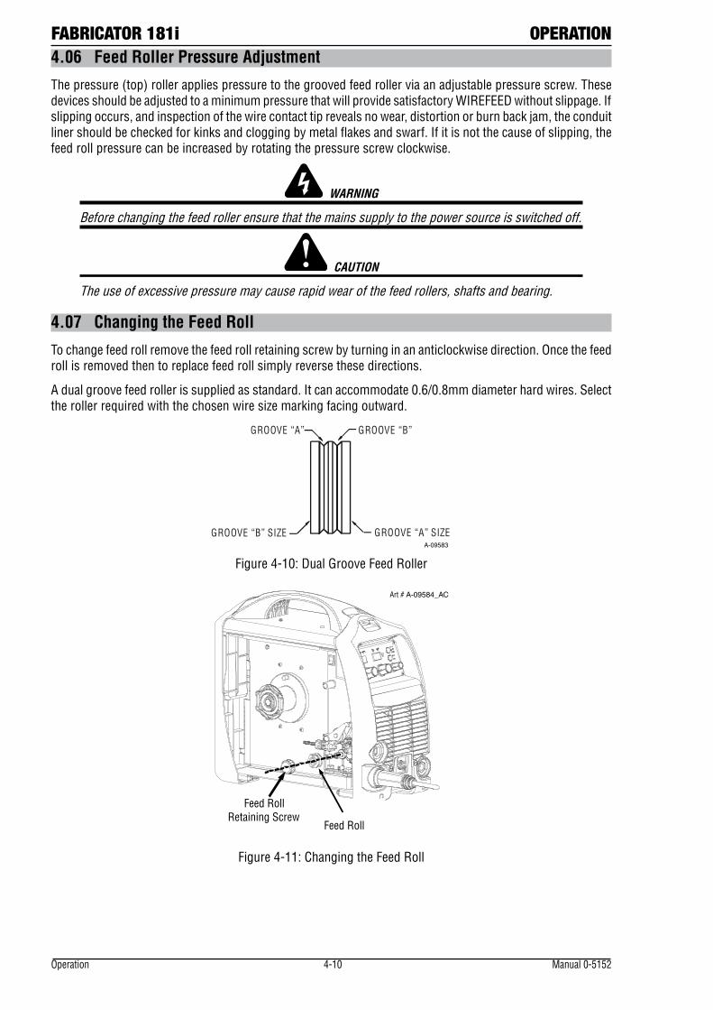
4.07 Changing the Feed Roll
To change feed roll remove the feed roll retaining screw by turning in an anticlockwise direction. Once the feed roll is removed then to replace feed roll simply reverse these directions.
A dual groove feed roller is supplied as standard. It can accommodate 0.6/0.8mm diameter hard wires. Select the roller required with the chosen wire size marking facing outward.
GROOVE “B”GROOVE “A”
GROOVE “A” SIZEGROOVE “B” SIZEA-09583
Figure 4-10: Dual Groove Feed Roller
Feed Roll Retaining Screw
Feed Roll
Art # A-09584_AC
Figure 4-11: Changing the Feed Roll
OPERATION FABRICATOR 181i
Manual 0-5152 4-11 Operation
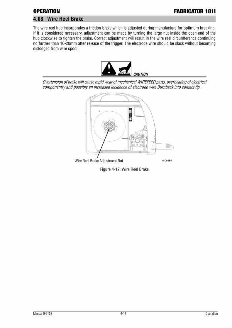
4.08 Wire Reel Brake
The wire reel hub incorporates a friction brake which is adjusted during manufacture for optimum breaking. If it is considered necessary, adjustment can be made by turning the large nut inside the open end of the hub clockwise to tighten the brake. Correct adjustment will result in the wire reel circumference continuing no further than 10-20mm after release of the trigger. The electrode wire should be slack without becoming dislodged from wire spool.
CAUTION
Overtension of brake will cause rapid wear of mechanical WIREFEED parts, overheating of electrical componentry and possibly an increased incidence of electrode wire Burnback into contact tip.
Wire Reel Brake Adjustment Nut A-09585
Figure 4-12: Wire Reel Brake
FABRICATOR 181i OPERATION
Operation 4-12 Manual 0-5152
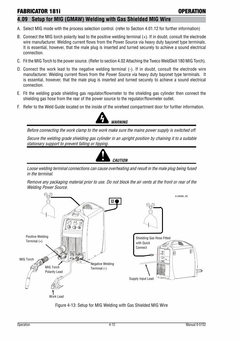
4.09 Setup for MIG (GMAW) Welding with Gas Shielded MIG Wire
A. Select MIG mode with the process selection control. (refer to Section 4.01.12 for further information)
B. Connect the MIG torch polarity lead to the positive welding terminal (+). If in doubt, consult the electrode wire manufacturer. Welding current flows from the Power Source via heavy duty bayonet type terminals. It is essential, however, that the male plug is inserted and turned securely to achieve a sound electrical connection.
C. Fit the MIG Torch to the power source. (Refer to section 4.02 Attaching the Tweco WeldSkill 180 MIG Torch).
D. Connect the work lead to the negative welding terminal (-). If in doubt, consult the electrode wire manufacturer. Welding current flows from the Power Source via heavy duty bayonet type terminals. It is essential, however, that the male plug is inserted and turned securely to achieve a sound electrical connection.
E. Fit the welding grade shielding gas regulator/flowmeter to the shielding gas cylinder then connect the shielding gas hose from the rear of the power source to the regulator/flowmeter outlet.
F. Refer to the Weld Guide located on the inside of the wirefeed compartment door for further information.
WARNING
Before connecting the work clamp to the work make sure the mains power supply is switched off.
Secure the welding grade shielding gas cylinder in an upright position by chaining it to a suitable stationary support to prevent falling or tipping.
CAUTION
Loose welding terminal connections can cause overheating and result in the male plug being fused in the terminal.
Remove any packaging material prior to use. Do not block the air vents at the front or rear of the Welding Power Source.
A-09586_AC
Shielding Gas Hose Fitted with Quick Connect
Supply Input Lead
Work Lead
Negative Welding Terminal (-)
Positive WeldingTerminal (+)
MIG Torch Polarity Lead
MIG Torch
Figure 4-13: Setup for MIG Welding with Gas Shielded MIG Wire
OPERATION FABRICATOR 181i
Manual 0-5152 4-13 Operation
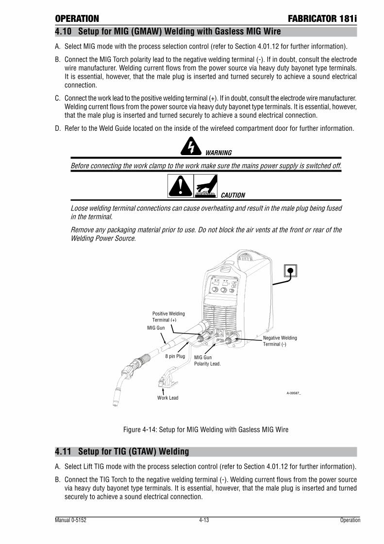
4.10 Setup for MIG (GMAW) Welding with Gasless MIG Wire
A. Select MIG mode with the process selection control (refer to Section 4.01.12 for further information).
B. Connect the MIG Torch polarity lead to the negative welding terminal (-). If in doubt, consult the electrode wire manufacturer. Welding current flows from the power source via heavy duty bayonet type terminals. It is essential, however, that the male plug is inserted and turned securely to achieve a sound electrical connection.
C. Connect the work lead to the positive welding terminal (+). If in doubt, consult the electrode wire manufacturer. Welding current flows from the power source via heavy duty bayonet type terminals. It is essential, however, that the male plug is inserted and turned securely to achieve a sound electrical connection.
D. Refer to the Weld Guide located on the inside of the wirefeed compartment door for further information.
WARNING
Before connecting the work clamp to the work make sure the mains power supply is switched off.
CAUTION
Loose welding terminal connections can cause overheating and result in the male plug being fused in the terminal.
Remove any packaging material prior to use. Do not block the air vents at the front or rear of the Welding Power Source.
A-09587_AD
MIG Gun Polarity Lead.
Negative Welding Terminal (-)
Positive Welding Terminal (+)
MIG Gun
8 pin Plug
Work Lead
Figure 4-14: Setup for MIG Welding with Gasless MIG Wire
4.11 Setup for TIG (GTAW) Welding
A. Select Lift TIG mode with the process selection control (refer to Section 4.01.12 for further information).
B. Connect the TIG Torch to the negative welding terminal (-). Welding current flows from the power source via heavy duty bayonet type terminals. It is essential, however, that the male plug is inserted and turned securely to achieve a sound electrical connection.
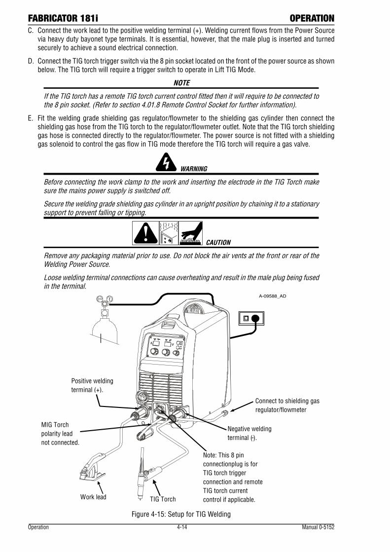
FABRICATOR 181i OPERATION
Operation 4-14 Manual 0-5152
C. Connect the work lead to the positive welding terminal (+). Welding current flows from the Power Source via heavy duty bayonet type terminals. It is essential, however, that the male plug is inserted and turned securely to achieve a sound electrical connection.
D. Connect the TIG torch trigger switch via the 8 pin socket located on the front of the power source as shown below. The TIG torch will require a trigger switch to operate in Lift TIG Mode.
NOTE
If the TIG torch has a remote TIG torch current control fitted then it will require to be connected to the 8 pin socket. (Refer to section 4.01.8 Remote Control Socket for further information).
E. Fit the welding grade shielding gas regulator/flowmeter to the shielding gas cylinder then connect the shielding gas hose from the TIG torch to the regulator/flowmeter outlet. Note that the TIG torch shielding gas hose is connected directly to the regulator/flowmeter. The power source is not fitted with a shielding gas solenoid to control the gas flow in TIG mode therefore the TIG torch will require a gas valve.
WARNING
Before connecting the work clamp to the work and inserting the electrode in the TIG Torch make sure the mains power supply is switched off.
Secure the welding grade shielding gas cylinder in an upright position by chaining it to a stationary support to prevent falling or tipping.
CAUTION
Remove any packaging material prior to use. Do not block the air vents at the front or rear of the Welding Power Source.
Loose welding terminal connections can cause overheating and result in the male plug being fused in the terminal.
A-09588_AD
Work lead
MIG Torch polarity lead not connected.
Note: This 8 pin connection plug is for TIG torch trigger connection and remote TIG torch current control if applicable. TIG Torch
Connect to shielding gas regulator/flowmeter
Negative welding terminal (-).
Positive welding terminal (+).
Figure 4-15: Setup for TIG Welding
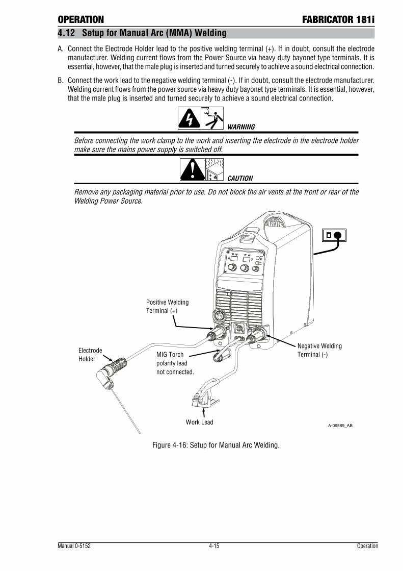
OPERATION FABRICATOR 181i
Manual 0-5152 4-15 Operation
4.12 Setup for Manual Arc (MMA) Welding
A. Connect the Electrode Holder lead to the positive welding terminal (+). If in doubt, consult the electrode manufacturer. Welding current flows from the Power Source via heavy duty bayonet type terminals. It is essential, however, that the male plug is inserted and turned securely to achieve a sound electrical connection.
B. Connect the work lead to the negative welding terminal (-). If in doubt, consult the electrode manufacturer. Welding current flows from the power source via heavy duty bayonet type terminals. It is essential, however, that the male plug is inserted and turned securely to achieve a sound electrical connection.
WARNING
Before connecting the work clamp to the work and inserting the electrode in the electrode holder make sure the mains power supply is switched off.
CAUTION
Remove any packaging material prior to use. Do not block the air vents at the front or rear of the Welding Power Source.
A-09589_AB
Negative Welding Terminal (-)
Positive Welding Terminal (+)
Work Lead
Electrode Holder
MIG Torch polarity lead not connected.
Figure 4-16: Setup for Manual Arc Welding.
FABRICATOR 181i OPERATION
Operation 4-16 Manual 0-5152
4.13 Leak Testing the System
Leak test the system before putting into operation.
1. Be sure that there is a valve in the downstream equipment to turn off the gas flow.
2. With the cylinder valve open, adjust the regulator to deliver the maximum required delivery flow rate.
3. Close the cylinder valve. Watch to see if the high pressure or contents gauge drops, if it does you have a leak in the connection between the regulator and the cylinder.
4. Once leak testing has been performed and there are no leaks in the system, slowly open the cylinder valve and proceed.
! WARNING
If a leak has been detected anywhere in the system, dis continue use and have the system repaired. DO NOT use leaking equipment. Do not attempt to repair a leaking system while the system is under pressure.
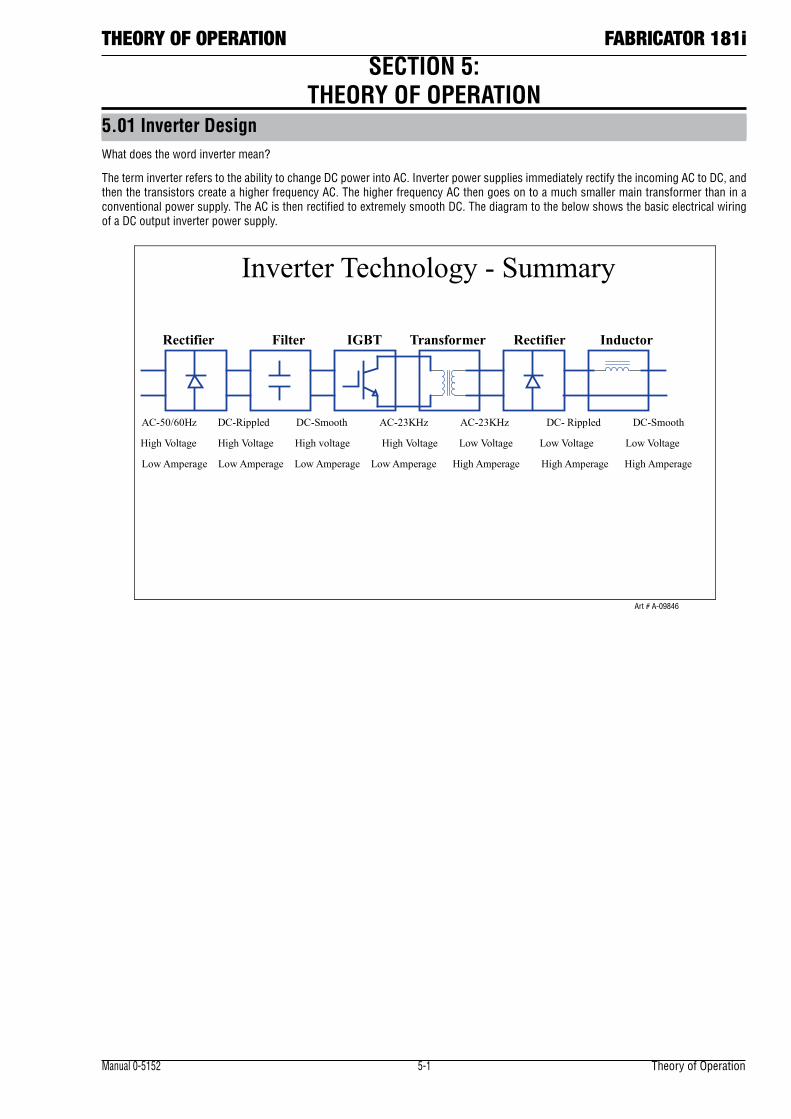
Manual 0-5152 5-1 Theory of Operation
THEORY OF OPERATION FABRICATOR 181i
5.01 Inverter DesignWhat does the word inverter mean?
The term inverter refers to the ability to change DC power into AC. Inverter power supplies immediately rectify the incoming AC to DC, and then the transistors create a higher frequency AC. The higher frequency AC then goes on to a much smaller main transformer than in a conventional power supply. The AC is then rectified to extremely smooth DC. The diagram to the below shows the basic electrical wiring of a DC output inverter power supply.
Inverter Technology - Summary
Rectifier Filter IGBT Transformer Rectifier Inductor
AC-50/60Hz DC-Rippled DC-Smooth AC-23KHz AC-23KHz DC- Rippled DC-Smooth
High Voltage High Voltage High voltage High Voltage Low Voltage Low Voltage Low Voltage
Low Amperage Low Amperage Low Amperage Low Amperage High Amperage High Amperage High Amperage
Art # A-09846
SECTION 5: THEORY OF OPERATION

Theory of Operation 5-2 Manual 0-5152
FABRICATOR 181i THEORY OF OPERATION
Notes
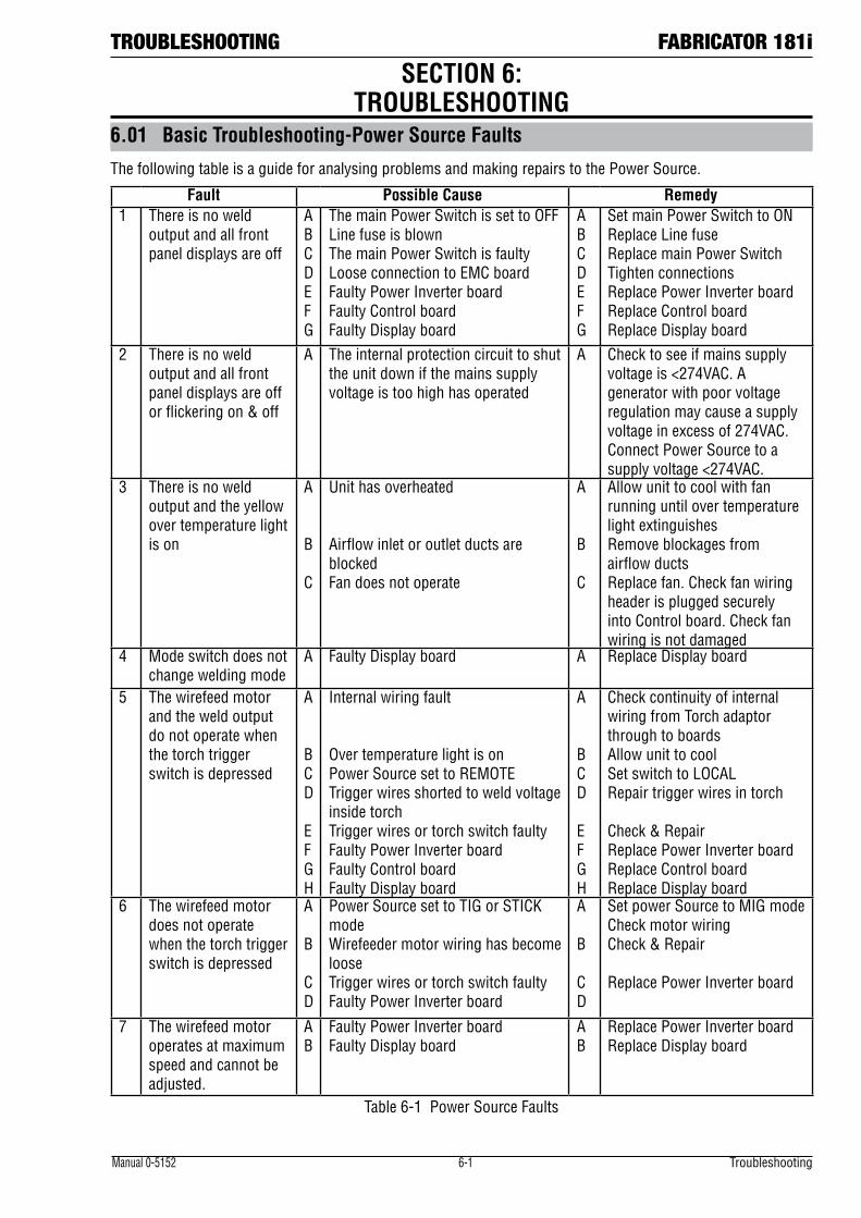
TROUBLESHOOTING FABRICATOR 181i
Manual 0-5152 6-1 Troubleshooting
6.01 Basic Troubleshooting-Power Source Faults
The following table is a guide for analysing problems and making repairs to the Power Source.
Fault Possible Cause Remedy1 There is no weld
output and all front panel displays are off
A B C D E F G
The main Power Switch is set to OFF Line fuse is blown The main Power Switch is faulty Loose connection to EMC board Faulty Power Inverter board Faulty Control board Faulty Display board
A B C D E F G
Set main Power Switch to ON Replace Line fuse Replace main Power Switch Tighten connections Replace Power Inverter board Replace Control board Replace Display board
2 There is no weld output and all front panel displays are off or flickering on & off
A The internal protection circuit to shut the unit down if the mains supply voltage is too high has operated
A Check to see if mains supply voltage is <274VAC. A generator with poor voltage regulation may cause a supply voltage in excess of 274VAC. Connect Power Source to a supply voltage <274VAC.
3 There is no weld output and the yellow over temperature light is on
A B C
Unit has overheated Airflow inlet or outlet ducts are blocked Fan does not operate
A B C
Allow unit to cool with fan running until over temperature light extinguishes Remove blockages from airflow ducts Replace fan. Check fan wiring header is plugged securely into Control board. Check fan wiring is not damaged
4 Mode switch does not change welding mode
A Faulty Display board A Replace Display board
5 The wirefeed motor and the weld output do not operate when the torch trigger switch is depressed
A B C D E F G H
Internal wiring fault Over temperature light is on Power Source set to REMOTE Trigger wires shorted to weld voltage inside torch Trigger wires or torch switch faulty Faulty Power Inverter board Faulty Control board Faulty Display board
A B C D E F G H
Check continuity of internal wiring from Torch adaptor through to boards Allow unit to cool Set switch to LOCAL Repair trigger wires in torch Check & Repair Replace Power Inverter board Replace Control board Replace Display board
6 The wirefeed motor does not operate when the torch trigger switch is depressed
A B C D
Power Source set to TIG or STICK mode Wirefeeder motor wiring has become loose Trigger wires or torch switch faulty Faulty Power Inverter board
A B C D
Set power Source to MIG mode Check motor wiring Check & Repair Replace Power Inverter board
7 The wirefeed motor operates at maximum speed and cannot be adjusted.
A B
Faulty Power Inverter board Faulty Display board
A B
Replace Power Inverter board Replace Display board
Table 6-1 Power Source Faults
SECTION 6: TROUBLESHOOTING
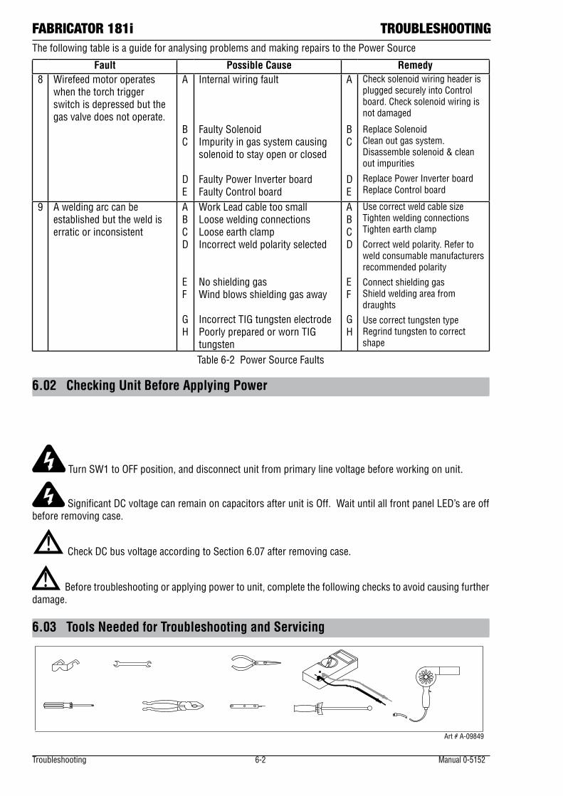
Troubleshooting 6-2 Manual 0-5152
FABRICATOR 181i TROUBLESHOOTINGThe following table is a guide for analysing problems and making repairs to the Power Source
Fault Possible Cause Remedy8 Wirefeed motor operates
when the torch trigger switch is depressed but the gas valve does not operate.
A B C D E
Internal wiring fault Faulty Solenoid Impurity in gas system causing solenoid to stay open or closed Faulty Power Inverter board Faulty Control board
A B C D E
Check solenoid wiring header is plugged securely into Control board. Check solenoid wiring is not damaged
Replace Solenoid Clean out gas system. Disassemble solenoid & clean out impurities
Replace Power Inverter board Replace Control board
9 A welding arc can be established but the weld is erratic or inconsistent
A B C D E F G H
Work Lead cable too small Loose welding connections Loose earth clamp Incorrect weld polarity selected No shielding gas Wind blows shielding gas away Incorrect TIG tungsten electrode Poorly prepared or worn TIG tungsten
A B C D E F G H
Use correct weld cable size Tighten welding connections Tighten earth clamp
Correct weld polarity. Refer to weld consumable manufacturers recommended polarity
Connect shielding gas Shield welding area from draughts
Use correct tungsten type Regrind tungsten to correct shape
Table 6-2 Power Source Faults
6.02 Checking Unit Before Applying Power
!
Turn SW1 to OFF position, and disconnect unit from primary line voltage before working on unit.
Significant DC voltage can remain on capacitors after unit is Off. Wait until all front panel LED’s are off before removing case.
! Check DC bus voltage according to Section 6.07 after removing case.
! Before troubleshooting or applying power to unit, complete the following checks to avoid causing further damage.
6.03 Tools Needed for Troubleshooting and Servicing
Art # A-09849
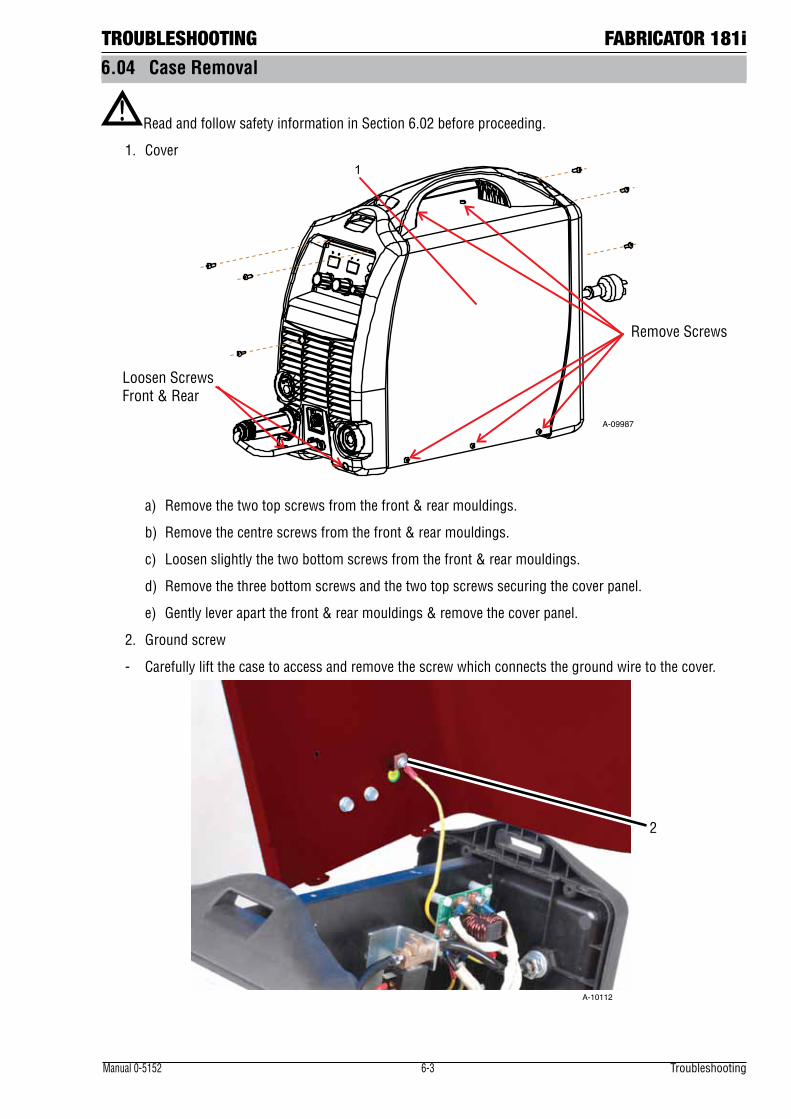
TROUBLESHOOTING FABRICATOR 181i
Manual 0-5152 6-3 Troubleshooting
6.04 Case Removal
! Read and follow safety information in Section 6.02 before proceeding.
1. Cover
Loosen Screws Front & Rear
Remove Screws
1
A-09987
a) Remove the two top screws from the front & rear mouldings.
b) Remove the centre screws from the front & rear mouldings.
c) Loosen slightly the two bottom screws from the front & rear mouldings.
d) Remove the three bottom screws and the two top screws securing the cover panel.
e) Gently lever apart the front & rear mouldings & remove the cover panel.
2. Ground screw
- Carefully lift the case to access and remove the screw which connects the ground wire to the cover.
2
A-10112
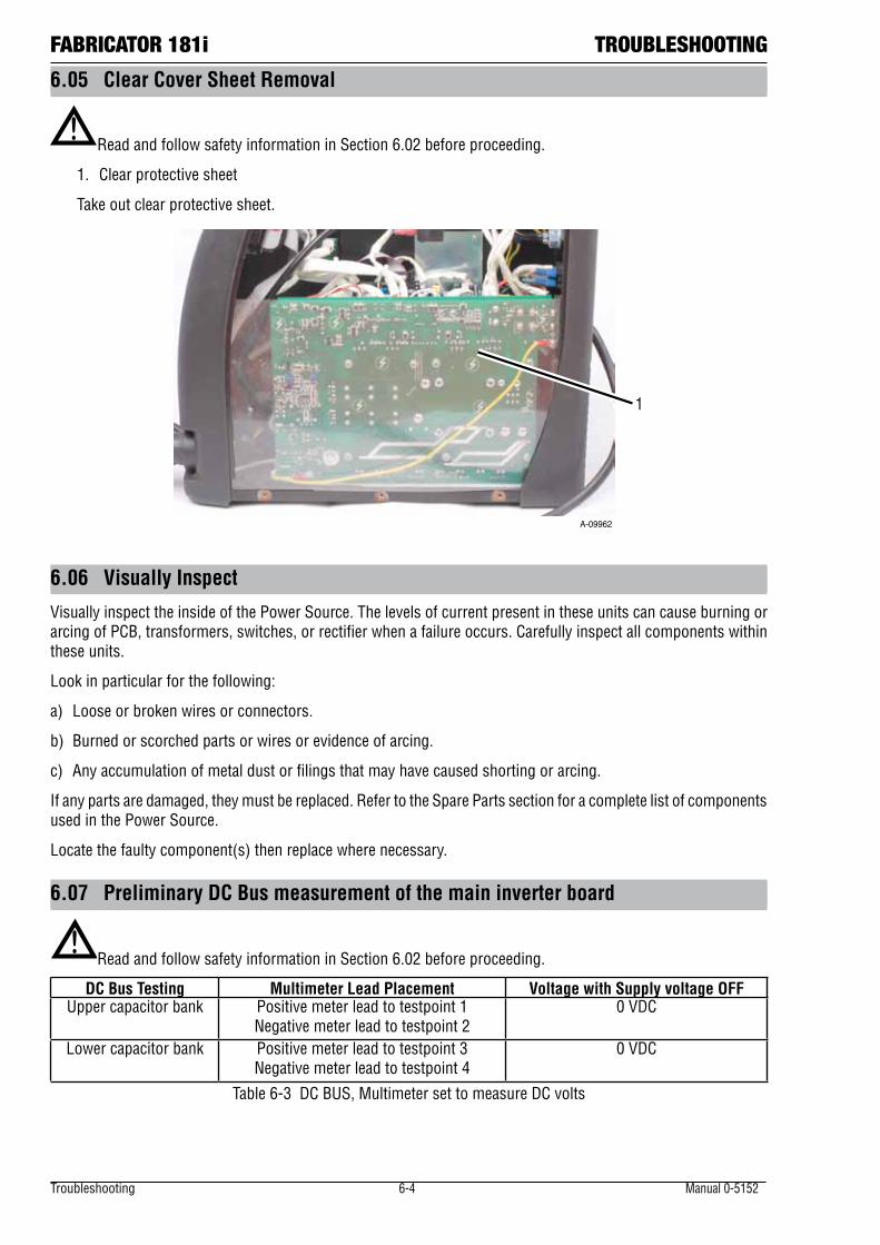
Troubleshooting 6-4 Manual 0-5152
FABRICATOR 181i TROUBLESHOOTING
6.05 Clear Cover Sheet Removal
!Read and follow safety information in Section 6.02 before proceeding.
1. Clear protective sheet
Take out clear protective sheet.
1
A-09962
6.06 Visually Inspect
Visually inspect the inside of the Power Source. The levels of current present in these units can cause burning or arcing of PCB, transformers, switches, or rectifier when a failure occurs. Carefully inspect all components within these units.
Look in particular for the following:
a) Loose or broken wires or connectors.
b) Burned or scorched parts or wires or evidence of arcing.
c) Any accumulation of metal dust or filings that may have caused shorting or arcing.
If any parts are damaged, they must be replaced. Refer to the Spare Parts section for a complete list of components used in the Power Source.
Locate the faulty component(s) then replace where necessary.
6.07 Preliminary DC Bus measurement of the main inverter board
!Read and follow safety information in Section 6.02 before proceeding.
DC Bus Testing Multimeter Lead Placement Voltage with Supply voltage OFFUpper capacitor bank Positive meter lead to testpoint 1
Negative meter lead to testpoint 20 VDC
Lower capacitor bank Positive meter lead to testpoint 3 Negative meter lead to testpoint 4
0 VDC
Table 6-3 DC BUS, Multimeter set to measure DC volts
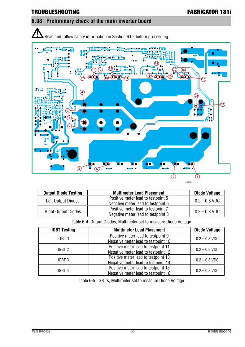
TROUBLESHOOTING FABRICATOR 181i
Manual 0-5152 6-5 Troubleshooting
6.08 Preliminary check of the main inverter board
! Read and follow safety information in Section 6.02 before proceeding.
4
3
1
2
5 6
7 8
10 9 12
11
14
13
16
1517 1819
20
21
22
A-09988
Output Diode Testing Multimeter Lead Placement Diode Voltage
Left Output Diodes Positive meter lead to testpoint 5 Negative meter lead to testpoint 6 0.2 – 0.8 VDC
Right Output Diodes Positive meter lead to testpoint 7 Negative meter lead to testpoint 8 0.2 – 0.8 VDC
Table 6-4 Output Diodes, Multimeter set to measure Diode Voltage
IGBT Testing Multimeter Lead Placement Diode Voltage
IGBT 1 Positive meter lead to testpoint 9 Negative meter lead to testpoint 10 0.2 – 0.8 VDC
IGBT 2Positive meter lead to testpoint 11 Negative meter lead to testpoint 12 0.2 – 0.8 VDC
IGBT 3Positive meter lead to testpoint 13 Negative meter lead to testpoint 14 0.2 – 0.8 VDC
IGBT 4Positive meter lead to testpoint 15 Negative meter lead to testpoint 16 0.2 – 0.8 VDC
Table 6-5 IGBT’s, Multimeter set to measure Diode Voltage
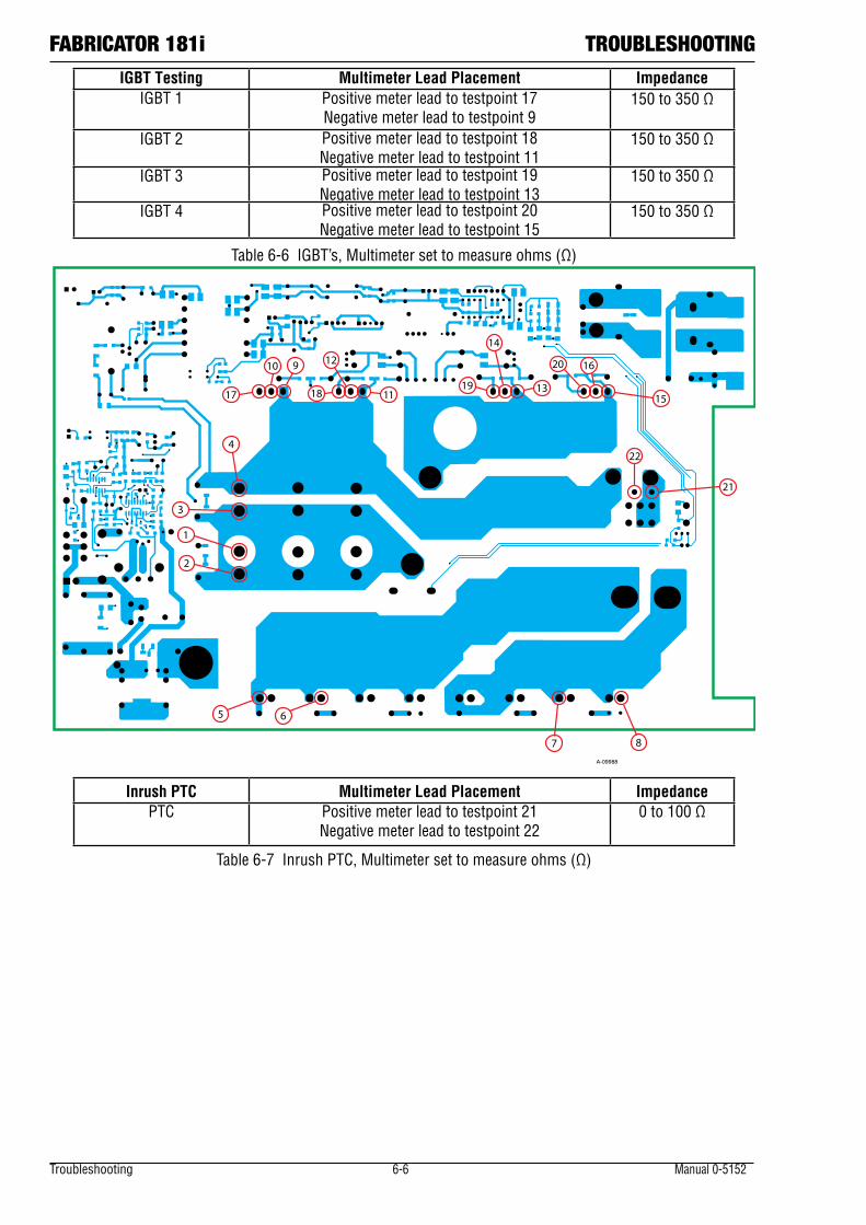
Troubleshooting 6-6 Manual 0-5152
FABRICATOR 181i TROUBLESHOOTINGIGBT Testing Multimeter Lead Placement Impedance
IGBT 1 Positive meter lead to testpoint 17 Negative meter lead to testpoint 9
150 to 350 Ω
IGBT 2 Positive meter lead to testpoint 18 Negative meter lead to testpoint 11
150 to 350 Ω
IGBT 3 Positive meter lead to testpoint 19 Negative meter lead to testpoint 13
150 to 350 Ω
IGBT 4 Positive meter lead to testpoint 20 Negative meter lead to testpoint 15
150 to 350 Ω
Table 6-6 IGBT’s, Multimeter set to measure ohms (Ω)
4
3
1
2
5 6
7 8
10 9 12
11
14
13
16
1517 1819
20
21
22
A-09988
Inrush PTC Multimeter Lead Placement ImpedancePTC Positive meter lead to testpoint 21
Negative meter lead to testpoint 220 to 100 Ω
Table 6-7 Inrush PTC, Multimeter set to measure ohms (Ω)
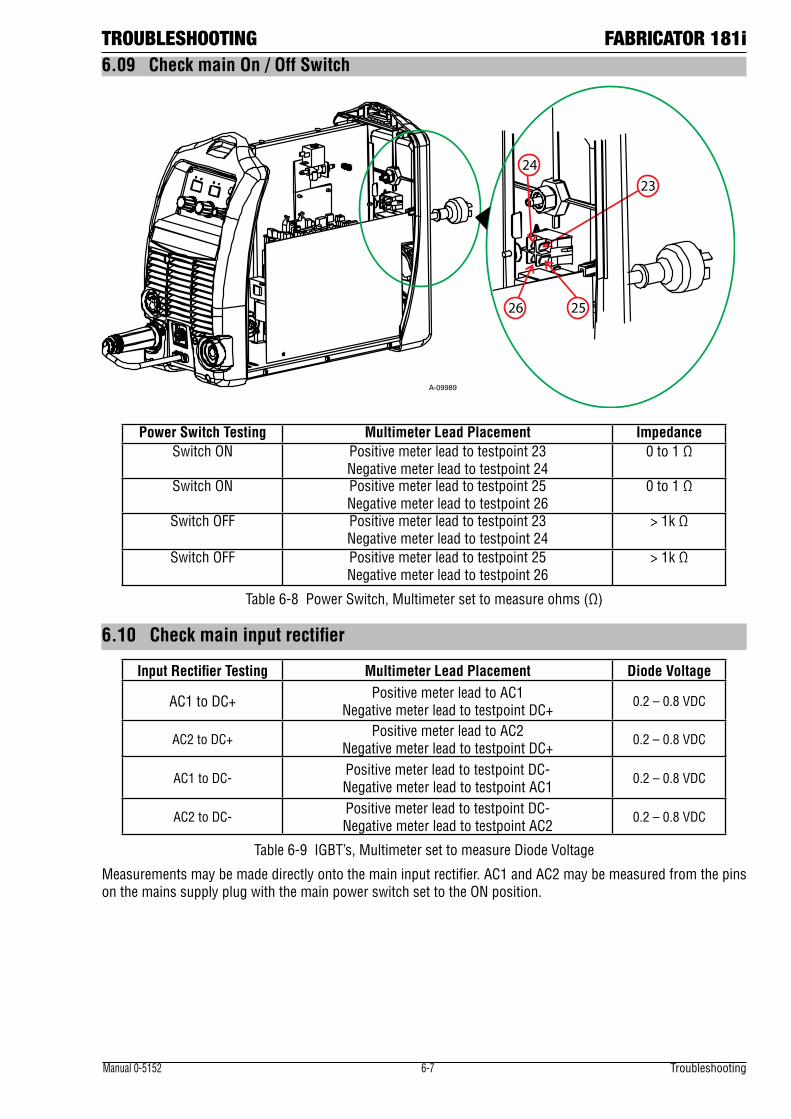
TROUBLESHOOTING FABRICATOR 181i
Manual 0-5152 6-7 Troubleshooting
6.09 Check main On / Off Switch
2324
2526
A-09989
Power Switch Testing Multimeter Lead Placement Impedance Switch ON Positive meter lead to testpoint 23
Negative meter lead to testpoint 240 to 1 Ω
Switch ON Positive meter lead to testpoint 25 Negative meter lead to testpoint 26
0 to 1 Ω
Switch OFF Positive meter lead to testpoint 23 Negative meter lead to testpoint 24
> 1k Ω
Switch OFF Positive meter lead to testpoint 25 Negative meter lead to testpoint 26
> 1k Ω
Table 6-8 Power Switch, Multimeter set to measure ohms (Ω)
6.10 Check main input rectifier
Input Rectifier Testing Multimeter Lead Placement Diode Voltage
AC1 to DC+ Positive meter lead to AC1 Negative meter lead to testpoint DC+
0.2 – 0.8 VDC
AC2 to DC+ Positive meter lead to AC2 Negative meter lead to testpoint DC+
0.2 – 0.8 VDC
AC1 to DC- Positive meter lead to testpoint DC- Negative meter lead to testpoint AC1
0.2 – 0.8 VDC
AC2 to DC- Positive meter lead to testpoint DC- Negative meter lead to testpoint AC2
0.2 – 0.8 VDC
Table 6-9 IGBT’s, Multimeter set to measure Diode Voltage
Measurements may be made directly onto the main input rectifier. AC1 and AC2 may be measured from the pins on the mains supply plug with the main power switch set to the ON position.
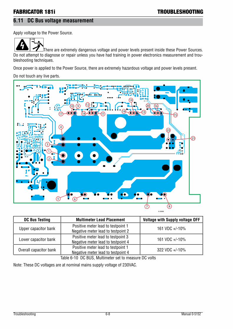
Troubleshooting 6-8 Manual 0-5152
FABRICATOR 181i TROUBLESHOOTING6.11 DC Bus voltage measurement
Apply voltage to the Power Source.
There are extremely dangerous voltage and power levels present inside these Power Sources. Do not attempt to diagnose or repair unless you have had training in power electronics measurement and trou-bleshooting techniques.
Once power is applied to the Power Source, there are extremely hazardous voltage and power levels present.
Do not touch any live parts.
4
3
1
2
5 6
7 8
10 9 12
11
14
13
16
1517 1819
20
21
22
A-09988
DC Bus Testing Multimeter Lead Placement Voltage with Supply voltage OFF
Upper capacitor bank Positive meter lead to testpoint 1 Negative meter lead to testpoint 2 161 VDC +/-10%
Lower capacitor bank Positive meter lead to testpoint 3 Negative meter lead to testpoint 4 161 VDC +/-10%
Overall capacitor bank Positive meter lead to testpoint 1 Negative meter lead to testpoint 4 322 VDC +/-10%
Table 6-10 DC BUS, Multimeter set to measure DC volts
Note: These DC voltages are at nominal mains supply voltage of 230VAC.
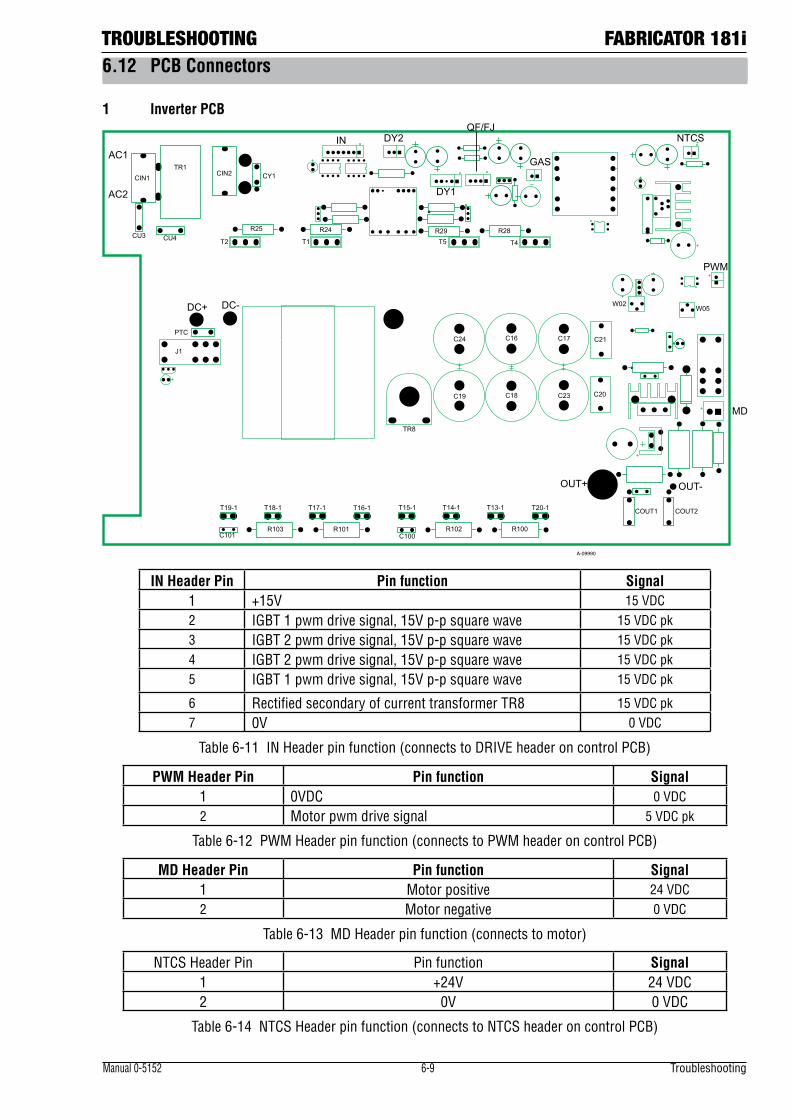
TROUBLESHOOTING FABRICATOR 181i
Manual 0-5152 6-9 Troubleshooting
6.12 PCB Connectors
1 Inverter PCB
AC1
AC2
CIN1TR1
CIN2 CY1
CU3 CU4 T2 T1
R24R25
IN DY2
DY1
R29 R28T5 T4
NTCS
PWM
W05W02
MD
C21
C20
C17
C23
C16
C18
C24
C19
COUT2COUT1
OUT-OUT+
T20-1T13-1T14-1T15-1
R100R102C100
T16-1T17-1T18-1T19-1
R101R103C101
PTC
DC+ DC-
J1
TR8
QF/FJ
GAS
A-09990
IN Header Pin Pin function Signal1 +15V 15 VDC2 IGBT 1 pwm drive signal, 15V p-p square wave 15 VDC pk3 IGBT 2 pwm drive signal, 15V p-p square wave 15 VDC pk4 IGBT 2 pwm drive signal, 15V p-p square wave 15 VDC pk5 IGBT 1 pwm drive signal, 15V p-p square wave 15 VDC pk
6 Rectified secondary of current transformer TR8 15 VDC pk7 0V 0 VDC
Table 6-11 IN Header pin function (connects to DRIVE header on control PCB)
PWM Header Pin Pin function Signal1 0VDC 0 VDC2 Motor pwm drive signal 5 VDC pk
Table 6-12 PWM Header pin function (connects to PWM header on control PCB)
MD Header Pin Pin function Signal1 Motor positive 24 VDC2 Motor negative 0 VDC
Table 6-13 MD Header pin function (connects to motor)
NTCS Header Pin Pin function Signal1 +24V 24 VDC2 0V 0 VDC
Table 6-14 NTCS Header pin function (connects to NTCS header on control PCB)
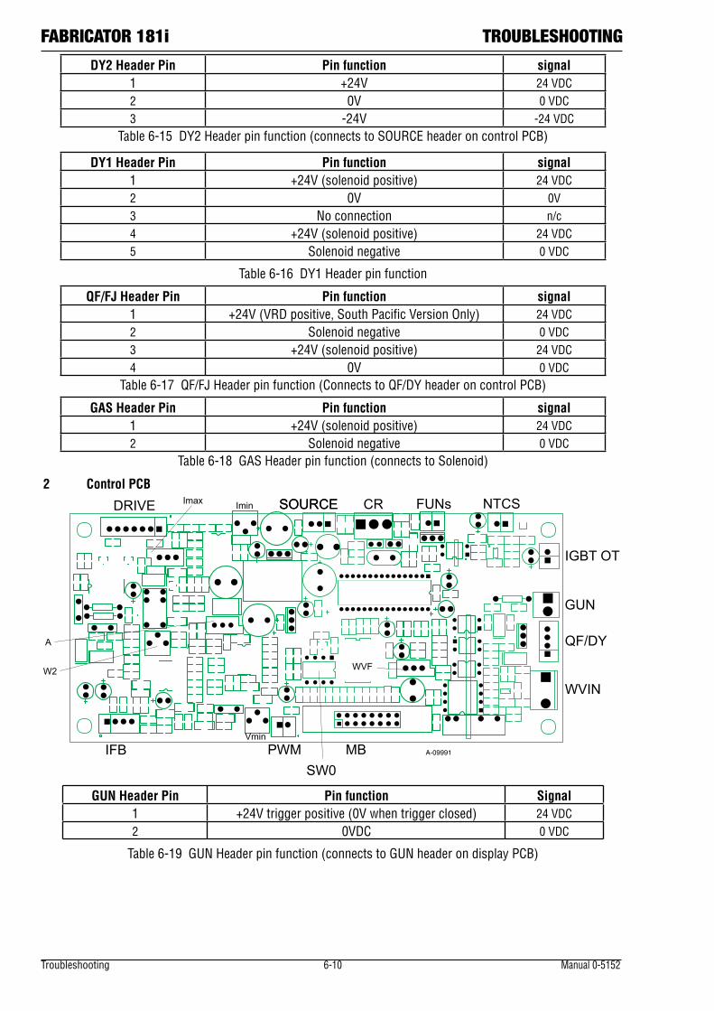
Troubleshooting 6-10 Manual 0-5152
FABRICATOR 181i TROUBLESHOOTING
DY2 Header Pin Pin function signal1 +24V 24 VDC2 0V 0 VDC3 -24V -24 VDC
Table 6-15 DY2 Header pin function (connects to SOURCE header on control PCB)
DY1 Header Pin Pin function signal1 +24V (solenoid positive) 24 VDC2 0V 0V3 No connection n/c4 +24V (solenoid positive) 24 VDC5 Solenoid negative 0 VDC
Table 6-16 DY1 Header pin function
QF/FJ Header Pin Pin function signal1 +24V (VRD positive, South Pacific Version Only) 24 VDC2 Solenoid negative 0 VDC3 +24V (solenoid positive) 24 VDC4 0V 0 VDC
Table 6-17 QF/FJ Header pin function (Connects to QF/DY header on control PCB)
GAS Header Pin Pin function signal1 +24V (solenoid positive) 24 VDC2 Solenoid negative 0 VDC
Table 6-18 GAS Header pin function (connects to Solenoid)
2 Control PCBImin
IFB PWMVmin
MB
GUN
QF/DY
WVIN
IGBT OT
NTCSFUNsSOURCE CRSOURCEDRIVE Imax
W2 WVF
A
SW0A-09991
GUN Header Pin Pin function Signal1 +24V trigger positive (0V when trigger closed) 24 VDC2 0VDC 0 VDC
Table 6-19 GUN Header pin function (connects to GUN header on display PCB)
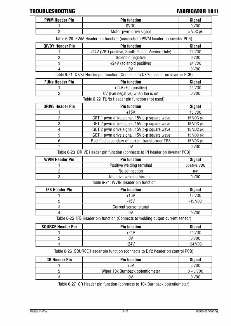
TROUBLESHOOTING FABRICATOR 181i
Manual 0-5152 6-11 Troubleshooting
PWM Header Pin Pin function Signal1 0VDC 0 VDC2 Motor pwm drive signal 5 VDC pk
Table 6-20 PWM Header pin function (connects to PWM header on inverter PCB)
QF/DY Header Pin Pin function Signal1 +24V (VRD positive, South Pacific Version Only) 24 VDC2 Solenoid negative 0 VDC3 +24V (solenoid positive) 24 VDC4 0V 0 VDC
Table 6-21 QF/FJ Header pin function (Connects to QF/FJ header on inverter PCB)
FUNs Header Pin Pin function Signal1 +24V (Fan positive) 24 VDC2 0V (Fan negative) when fan is on 0 VDC
Table 6-22 FUNs Header pin function (not used)
DRIVE Header Pin Pin function Signal1 +15V 15 VDC2 IGBT 1 pwm drive signal, 15V p-p square wave 15 VDC pk3 IGBT 2 pwm drive signal, 15V p-p square wave 15 VDC pk4 IGBT 2 pwm drive signal, 15V p-p square wave 15 VDC pk5 IGBT 1 pwm drive signal, 15V p-p square wave 15 VDC pk6 Rectified secondary of current transformer TR8 15 VDC pk7 0V 0 VDCTable 6-23 DRIVE Header pin function (connects to IN header on inverter PCB)
WVIN Header Pin Pin function Signal1 Positive welding terminal positive VDC2 No connection n/c3 Negative welding terminal 0 VDC
Table 6-24 WVIN Header pin function
IFB Header Pin Pin function Signal1 +15V 15 VDC2 -15V -15 VDC3 Current sensor signal4 0V 0 VDC
Table 6-25 IFB Header pin function (Connects to welding output current sensor)
SOURCE Header Pin Pin function Signal1 +24V 24 VDC2 0V 0 VDC3 -24V -24 VDC
Table 6-26 SOURCE Header pin function (connects to DY2 header on control PCB)
CR Header Pin Pin function Signal1 +5V 5 VDC2 Wiper 10k Burnback potentiometer 0 – 5 VDC3 0V 0 VDC
Table 6-27 CR Header pin function (connects to 10k Burnback potentiometer)
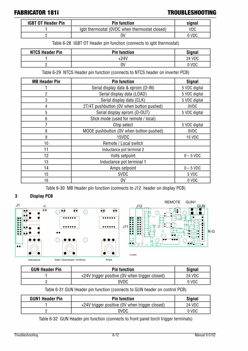
Troubleshooting 6-12 Manual 0-5152
FABRICATOR 181i TROUBLESHOOTING
IGBT OT Header Pin Pin function signal1 Igbt thermostat (0VDC when thermostat closed) VDC2 0V 0 VDC
Table 6-28 IGBT OT Header pin function (connects to igbt thermostat)
NTCS Header Pin Pin function Signal1 +24V 24 VDC2 0V 0 VDC
Table 6-29 NTCS Header pin function (connects to NTCS header on inverter PCB)
MB Header Pin Pin function Signal1 Serial display data & eprom (D-IN) 5 VDC digital2 Serial display data (LOAD) 5 VDC digital3 Serial display data (CLK) 5 VDC digital4 2T/4T pushbutton (0V when button pushed) 0VDC5 Serial display eprom (D-OUT) 5 VDC digital6 Stick mode (used for remote / local)7 Chip select 5 VDC digital8 MODE pushbutton (0V when button pushed) 0VDC9 15VDC 15 VDC10 Remote / Local switch11 Inductance pot terminal 212 Volts setpoint 0 – 5 VDC13 Inductance pot terminal 114 Amps setpoint 0 – 5 VDC15 5VDC 5 VDC16 0V 0 VDC
Table 6-30 MB Header pin function (connects to J12 header on display PCB)
3 Display PCB
J12
Volts / Downslope / Arcforce
GUN1GUN
R-GJ11
REMOTE
AmpsInductance
JCJ1
A-09992
GUN Header Pin Pin function Signal1 +24V trigger positive (0V when trigger closed) 24 VDC2 0VDC 0 VDC
Table 6-31 GUN Header pin function (connects to GUN header on control PCB)
GUN1 Header Pin Pin function Signal1 +24V trigger positive (0V when trigger closed) 24 VDC2 0VDC 0 VDC
Table 6-32 GUN Header pin function (connects to front panel torch trigger terminals)
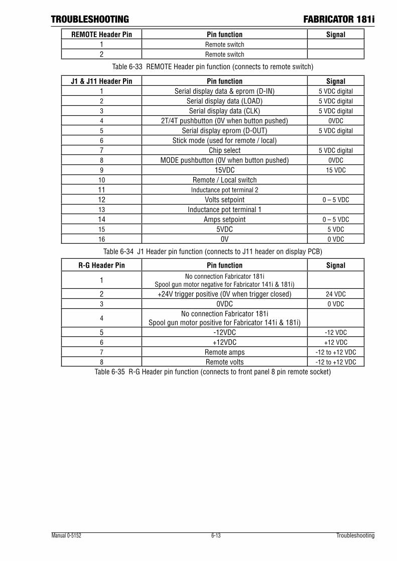
TROUBLESHOOTING FABRICATOR 181i
Manual 0-5152 6-13 Troubleshooting
REMOTE Header Pin Pin function Signal1 Remote switch2 Remote switch
Table 6-33 REMOTE Header pin function (connects to remote switch)
J1 & J11 Header Pin Pin function Signal1 Serial display data & eprom (D-IN) 5 VDC digital2 Serial display data (LOAD) 5 VDC digital3 Serial display data (CLK) 5 VDC digital4 2T/4T pushbutton (0V when button pushed) 0VDC5 Serial display eprom (D-OUT) 5 VDC digital6 Stick mode (used for remote / local)7 Chip select 5 VDC digital8 MODE pushbutton (0V when button pushed) 0VDC9 15VDC 15 VDC10 Remote / Local switch11 Inductance pot terminal 212 Volts setpoint 0 – 5 VDC13 Inductance pot terminal 114 Amps setpoint 0 – 5 VDC15 5VDC 5 VDC16 0V 0 VDC
Table 6-34 J1 Header pin function (connects to J11 header on display PCB)
R-G Header Pin Pin function Signal
1 No connection Fabricator 181i Spool gun motor negative for Fabricator 141i & 181i)
2 +24V trigger positive (0V when trigger closed) 24 VDC3 0VDC 0 VDC
4No connection Fabricator 181i
Spool gun motor positive for Fabricator 141i & 181i)5 -12VDC -12 VDC6 +12VDC +12 VDC7 Remote amps -12 to +12 VDC8 Remote volts -12 to +12 VDC
Table 6-35 R-G Header pin function (connects to front panel 8 pin remote socket)
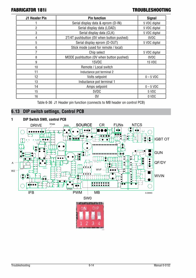
Troubleshooting 6-14 Manual 0-5152
FABRICATOR 181i TROUBLESHOOTING
J1 Header Pin Pin function Signal1 Serial display data & eprom (D-IN) 5 VDC digital2 Serial display data (LOAD) 5 VDC digital3 Serial display data (CLK) 5 VDC digital4 2T/4T pushbutton (0V when button pushed) 0VDC5 Serial display eprom (D-OUT) 5 VDC digital6 Stick mode (used for remote / local)7 Chip select 5 VDC digital8 MODE pushbutton (0V when button pushed) 0VDC9 15VDC 15 VDC10 Remote / Local switch11 Inductance pot terminal 212 Volts setpoint 0 – 5 VDC13 Inductance pot terminal 114 Amps setpoint 0 – 5 VDC15 5VDC 5 VDC16 0V 0 VDC
Table 6-36 J1 Header pin function (connects to MB header on control PCB)
6.13 DIP switch settings, Control PCB
1 DIP Switch SW0, control PCBImin
IFB PWMVmin
MB
GUN
QF/DY
WVIN
IGBT OT
NTCSFUNsSOURCE CRSOURCEDRIVE Imax
W2 WVF
A
SW0A-09993
A-09998
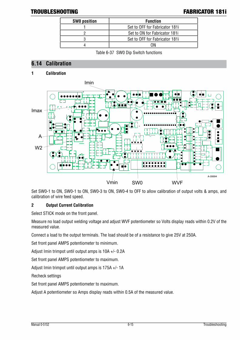
TROUBLESHOOTING FABRICATOR 181i
Manual 0-5152 6-15 Troubleshooting
SW0 position Function1 Set to OFF for Fabricator 181i2 Set to ON for Fabricator 181i3 Set to OFF for Fabricator 181i4 ON
Table 6-37 SW0 Dip Switch functions
6.14 Calibration
1 Calibration
Imin
Vmin
Imax
W2
WVF
A
SW0A-09994
Set SW0-1 to ON, SW0-1 to ON, SW0-3 to ON, SW0-4 to OFF to allow calibration of output volts & amps, and calibration of wire feed speed.
2 Output Current Calibration
Select STICK mode on the front panel.
Measure no load output welding voltage and adjust WVF potentiometer so Volts display reads within 0.2V of the measured value.
Connect a load to the output terminals. The load should be of a resistance to give 25V at 250A.
Set front panel AMPS potentiometer to minimum.
Adjust Imin trimpot until output amps is 10A +/- 0.2A
Set front panel AMPS potentiometer to maximum.
Adjust Imin trimpot until output amps is 175A +/- 1A
Recheck settings
Set front panel AMPS potentiometer to maximum.
Adjust A potentiometer so Amps display reads within 0.5A of the measured value.
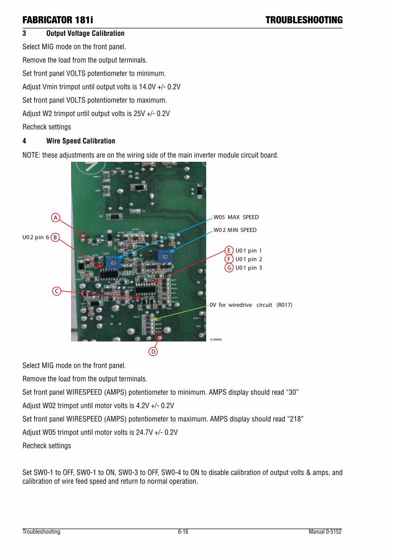
Troubleshooting 6-16 Manual 0-5152
FABRICATOR 181i TROUBLESHOOTING3 Output Voltage Calibration
Select MIG mode on the front panel.
Remove the load from the output terminals.
Set front panel VOLTS potentiometer to minimum.
Adjust Vmin trimpot until output volts is 14.0V +/- 0.2V
Set front panel VOLTS potentiometer to maximum.
Adjust W2 trimpot until output volts is 25V +/- 0.2V
Recheck settings
4 Wire Speed Calibration
NOTE: these adjustments are on the wiring side of the main inverter module circuit board.
A
BU02 pin 6
C
D
E U01 pin 1F U01 pin 2G U01 pin 3
0V for wiredrive circuit (R017)
W02 MIN SPEED
W05 MAX SPEED
A-09995
Select MIG mode on the front panel.
Remove the load from the output terminals.
Set front panel WIRESPEED (AMPS) potentiometer to minimum. AMPS display should read “30”
Adjust W02 trimpot until motor volts is 4.2V +/- 0.2V
Set front panel WIRESPEED (AMPS) potentiometer to maximum. AMPS display should read “218”
Adjust W05 trimpot until motor volts is 24.7V +/- 0.2V
Recheck settings
Set SW0-1 to OFF, SW0-1 to ON, SW0-3 to OFF, SW0-4 to ON to disable calibration of output volts & amps, and calibration of wire feed speed and return to normal operation.
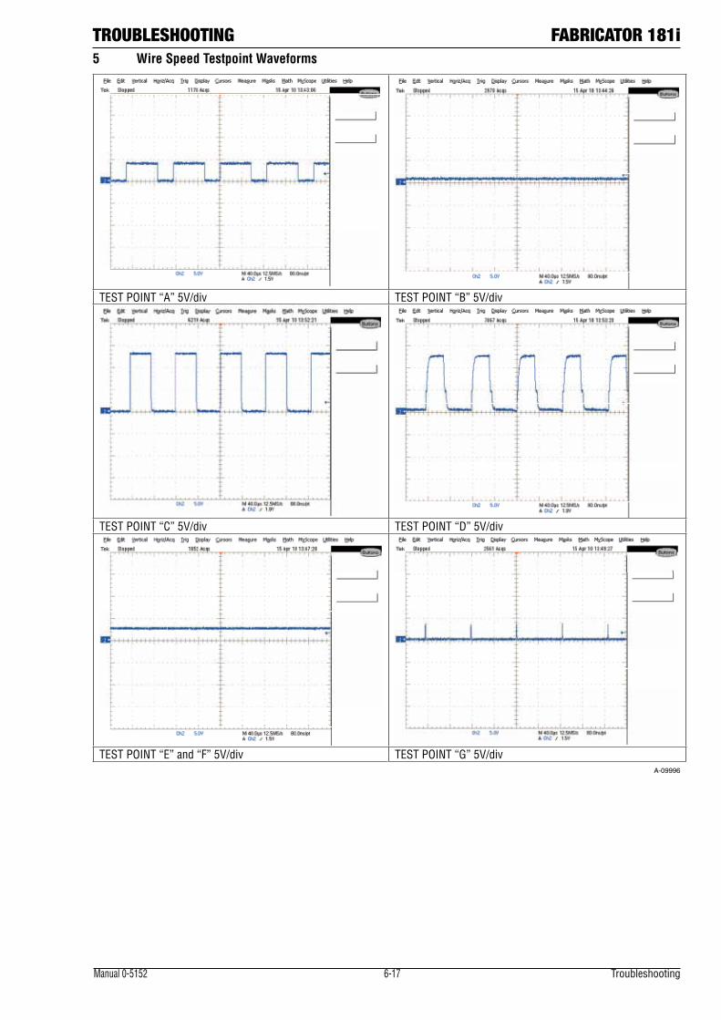
TROUBLESHOOTING FABRICATOR 181i
Manual 0-5152 6-17 Troubleshooting
5 Wire Speed Testpoint Waveforms
TEST POINT “A” 5V/div TEST POINT “B” 5V/div
TEST POINT “C” 5V/div TEST POINT “D” 5V/div
TEST POINT “E” and “F” 5V/div TEST POINT “G” 5V/div A-09996
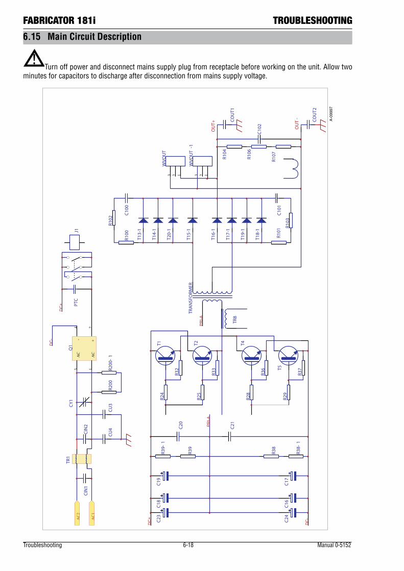
Troubleshooting 6-18 Manual 0-5152
FABRICATOR 181i TROUBLESHOOTING
6.15 Main Circuit Description
!Turn off power and disconnect mains supply plug from receptacle before working on the unit. Allow two
minutes for capacitors to discharge after disconnection from mains supply voltage.
AC
1
AC
3
+2
-4
Q1
TR1
C19
C16
C17
R25
R24
R32
R33
T18-1
T16-1
T14-1
T17-1
T15-1
T13-1
R102
R100 R101
R103
C100
COUT1
COUT2
C18
TRANSFORM
ERR3
9
C20
C21
R38
PR
I-A
PR
I-A
TR8
DC
+
C23
C24
R39-
1
R38-
1
R104
C102
123WVO
UT
C101
R107R106
123WVO
UT-1
PTC
J1
CIN1
CIN2
CU3
CU4
R200
CY1
R200
-1
DC
-
DC
-
DC
+
AC2
AC1
T19-1
T20-1
OUT-
OUT+
T1 T2
R29
R28
R36
R37
T4
T5
A-0
9997
TROUBLESHOOTING FABRICATOR 181i
Manual 0-5152 6-19 Troubleshooting
The mains supply voltage is connected via a double pole switch to the input rectifier Q1 through an EMC filter. Overvoltage protection is provided by varistor CY1.
The rectifier output charges the main capacitor bank (C16, C17, C18, C19, C22 and C23) to high voltage. Inrush current limiting is provided by a PTC which is then bypassed by relay J1 after a few seconds.
The primary igbt transistors (T1, T2, T4, and T5) switch the transformer primary at high frequency and varying duty cycle. The transformer return wire is taken from the junction of the capacitors C20 and C21 (the voltage at this point is approximately half the DC bus voltage).
Secondary output voltage from the transformer is rectified by the output diodes (T13, T14, T15, T16, T17, T18, T19, and T20) to DC. This DC is controlled by the PWM of the primary side igbt transistors, and is filtered by an inductor before connecting to the welding output terminals.
A thermal overload device (thermistor) is fixed to the rectifier heatsink. When an over temperature occurs, the control circuit inhibits the trigger, gas solenoid, wire drive system and the welding output. The thermal overload indicator LED on the front panel is illuminated.
The current transformer TR8 provides a signal to the control circuit to indicate both transformer primary current, and also detect transformer saturation. The Hall effect current sensor is powered from regulated + & - 15VDC supplies and provides a voltage signal proportional to the output DC welding current to allow the control circuit to regulate welding current.
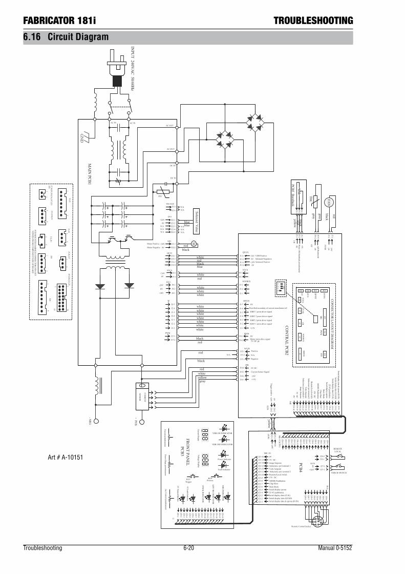
Troubleshooting 6-20 Manual 0-5152
FABRICATOR 181i TROUBLESHOOTING
6.16 Circuit Diagram
GN
D
AC INAC INAC OUT
AC OUT
DC IN
DC IN
CURREN
T
SENSO
R
FAN
THC
redwhiteyellow
gray
black
red
J24J10
J8 CO
NN
ECTOR LA
YO
UT D
IAG
RAM
J19
J1J3
J7
MA
IN PCB1
CON
TRAL PCB2
PCB3
redblack
whitewhitewhitewhitewhitewhitewhite
whitewhite
white
blackred
yellow
redwhite
whiteredblackblue
gray
gray
red
black
J13
J16
FRON
T PAN
EL PCB4
PTC
INPU
T 240VA
C 50/60Hz
IFB
WVIN
PWM
DRIVE
SOURCE
NTCS
QF/DY
CR
OT FU
NS
0V
J12(CPU)
PWM
IN
DY2
NTCS
QF/FJ
PCB5Burnback
17
J1-1
J1-2
J1-3
J1-4
J1-5
J1-6
J1-7
J2-1
J2-2
J2-3
J2-4
J2-5
J2-6
J2-7
J1,J21
3J3,J4
J3-1
J3-2
J3-3
J4-1
J4-2
J4-3
13
J7,J8,J9,J10,J16,J17,J21
J5-1J5-2J5-3
J6-1J6-2J6-3
2
J7-2
J7-1
J10-1J10-2
J8-1
J8-2
J9-1
J9-2
J5,J6,J15
4
J13,J14,18
J13-1J13-2J13-3J13-4
J14-1J14-2J14-3J14-4
2
J12,J11J15-1
J15-2
J16-1
J16-2
J17-1
J17-2
J18-1
J18-2
J18-3
J18-4PCB M
OU
NTED
HA
RNESS CO
NN
ECTORS PIN
OU
TV
IEWED
FROM
COM
PON
ENT SID
E OF BO
ARD
DY1J22-1J22-2J22-3J22-4J22-5
5
J20
+24V0V
N/A
+24V0V
J21-1
J21-2
TIG GAS
+24V
0V
-24V
+24V0V
+24V0V
VDR PositiveSolenoid NegatioveSolenoid Positive
+15V
IGBT 1 pwm driver signal
IGBT 2 pwm driver signal
IGBT 2 pwm driver signal
IGBT 1 pwm driver signal
Rectified secondary of current transformer tr8
0V
Motor pwm drive signal5V DC pk
0V
J15-3
Positive
N/A
Negative
+15V-15V
Current Sensor Signal
0V DC
24V0V
igbt thermostat
0V
MB
J19-1J19-2J19-3J19-4J19-5J19-6J19-7J19-8J19-9J19-10J19-11J19-12J19-13J19-14J19-15
J19-165V
DC
Am
ps Setpoint
Volts Setpoint
Inductance pot terminal 1
Inductance pot terminal 2
Remote/Local sw
itch15V
DC
MO
DE Pushbutton
Chip SlectStick M
odeSerial display eprom
2T/4T pushbuttonSerial display data (CLK
)Serial display data (LO
AD
)Serial display data &
eprom (D
-IN)
+5VW
iper 10k Burnback potentiometer
0V
blueblue
N/AN/A
N/AN/AN/A
15
216
J5
J15
J18
DRIV
E
PWM
WV
INIFB
MB
SOU
RCE
GU
N
QF/D
Y
OT
FUN
SCR
NTC
S
J20-1J20-2J20-3J20-4J20-5J20-6J20-7J20-8J20-9J20-10J20-11J20-12J20-13J20-14J20-15
J20-16M
B
J29-1J29-2J29-3J29-4J29-5J29-6J29-7J29-8J29-9J29-10J29-11J29-12J29-13J29-14J29-15J29-16
J1
MD+24V
0V
Motor Positive
Motor Negative
M
J12-1
J12-2red
black
N/AN/A
N/A
J11
0V
J23-1J23-2J23-3J23-4J23-5J23-6J23-7J23-8J23-9J23-10J23-11J23-12J23-13J23-14J23-15J23-16
5V DCAmps Setpoint
Volts SetpointInductance pot terminal 1
Inductance pot terminal 2Remote/Local switch15V DCMODE PushbuttonChip SlectStick ModeSerial display eprom2T/4T pushbuttonSerial display data (CLK)Serial display data (LOAD)Serial display data & eprom (D-IN)
MB
J24-1J24-2
yellowyellow
J25-1J25-2
GU
N
+24V0V
Trigger positiveG
UN
1
J26-1J26-2
LOCALREMOTE
J27-1J27-2
J26
J28-1J28-2J28-3J28-4J28-5J28-6J28-7J28-8
GUN
+24V
0V
+24V0V
Current Disply
Voltage D
isplay
Arc Control potentiom
eterCurrent potentiom
eterD
own Slope potentiom
eter
KG3Trigger
2T Norm
al Idicator
4T Latch Indcator
Process
MIG
IND
ICA
TOR
LIFT TIG IN
DIC
ATO
R
STICK IN
DICA
TOR
KG4
12
35
68
ON
4
8J28
R-G
J19,J20,J23,29
Solenoid Value
1
11
11
1
12
3
TORCH SWITCH
Remote Control Socket
+ POS
- NEG
Power Indicator
Fault Indicator
VDR ON INDICATOR
VDR OFF INDICATOR
Art # A-10151
Manual 0-5152 7-1 Disassembly Procedure
DISASSEMBLY PROCEDURE FABRICATOR 181i
7.01 Safety Precautions for Disassembly
!Read and follow safety information in Section 6.02 before proceeding.
Unplug unit before beginning Disassembly procedure.
SECTION 7: DISASSEMBLY PROCEDURE
FABRICATOR 181i DISASSEMBLY PROCEDURE
Disassembly Procedure 7-2 Manual 0-5152
7.02 Control Board Removal
! Read and follow safety information in Section 6.02 before proceeding with disassembly
Remove case (refer to 6.04) before remove control board.
Refer to graphics on page 7-3.
1. M4 Screw. Remove 4 screws from Control panel.
2 Disconnect DRIVE harness from DRIVE connector.
3. Disconnect SOURCE harness from SOURCE connector.
4. Disconnect CR harness from CR connector.
5. Disconnect FUNs harness from FUNs connector.
6. Disconnect NTCS harness from NTCS connector.
7. Disconnect IGBT OT harness from IGBT OT connector.
8. Disconnect GUN harness from GUN connector.
9. Disconnect QF/DY harness from QF/DY connector.
10. Disconnect WVIN harness from WVIN connector.
11 Disconnect MB harness from MB connector.
12. Disconnect PWM harness from PWM connector.
13. Disconnect IFB harness from IFB connector.
Ensure to unplug all harness from the main control PCB.
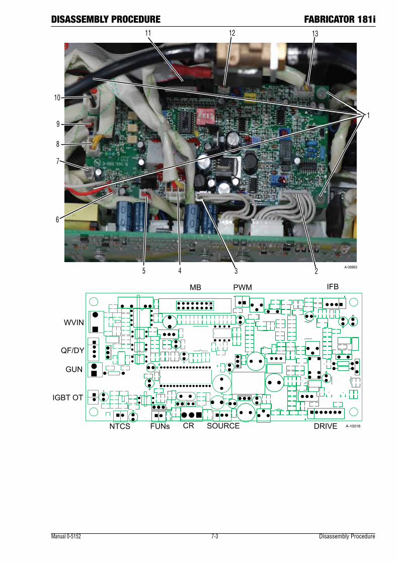
Manual 0-5152 7-3 Disassembly Procedure
DISASSEMBLY PROCEDURE FABRICATOR 181i
1
5 4 3 2
6
13
7
8
9
12 11
10
A-09963
IFBPWMMB
GUN
QF/DY
WVIN
IGBT OT
NTCS FUNs CR SOURCE DRIVE A-10018

FABRICATOR 181i DISASSEMBLY PROCEDURE
Disassembly Procedure 7-4 Manual 0-5152
7.03 Front Panel Assembly Removal
! Read and follow safety information in Section 6.02 before proceeding with disassembly
1. Screws on front panel
2 Negative output terminal bolts. Unscrew Negative output terminal bolts.
3. Torch cable bolts. Unscrew torch cable terminal bolts.
4. Positive output terminal bolts. Unscrew output terminal bolts.
5. Unplug two red wire harness from PCB as shown in photo on following page.
1
A-10110
2
3
4
A-09964
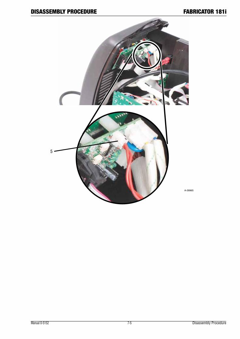
Manual 0-5152 7-5 Disassembly Procedure
DISASSEMBLY PROCEDURE FABRICATOR 181i
A-09965
5

FABRICATOR 181i DISASSEMBLY PROCEDURE
Disassembly Procedure 7-6 Manual 0-5152
7.04 Front Panel (Operator Interface) Circuit Board PCB3 Removal
! Read and follow safety information in Section 6.02 before proceeding with disassembly
1. Remove Control Panel screw (4).
2. Front Panel PCB.
3. Remote control PCB.1
A-10000
A-10115
3
2
A-10001

Manual 0-5152 7-7 Disassembly Procedure
DISASSEMBLY PROCEDURE FABRICATOR 181i7.05 Back Panel Removal
!Read and follow safety information in Section 6.02 before proceeding with disassembly
1. ON/OFF switch.
Ground wire screw.
Disconnect Input cord ground wire from Main Power PCB1 using a 1/4" wench.
2. Terminal from supply cable. Disconnect two terminals from switch.
3. Wire from Main PCB1.
Disconnect the two wires from switch.
Rear panel mounting SCREW.
Remove screw holding rear panel to chassis.
4. Disconnect harness from J8 connector on Control PCB2 and carefully lift the wire free from the unit.
1
2
3
A-09968
A-10003
4
A-10004
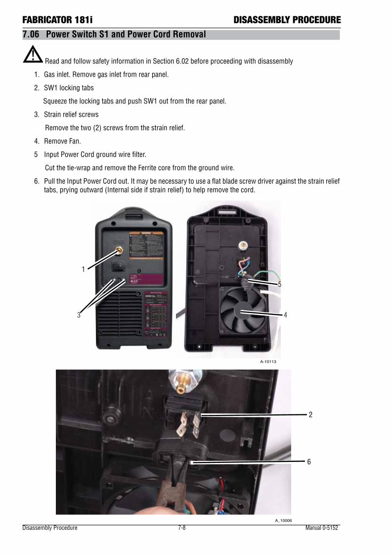
FABRICATOR 181i DISASSEMBLY PROCEDURE
Disassembly Procedure 7-8 Manual 0-5152
7.06 Power Switch S1 and Power Cord Removal
! Read and follow safety information in Section 6.02 before proceeding with disassembly
1. Gas inlet. Remove gas inlet from rear panel.
2. SW1 locking tabs
Squeeze the locking tabs and push SW1 out from the rear panel.
3. Strain relief screws
Remove the two (2) screws from the strain relief.
4. Remove Fan.
5 Input Power Cord ground wire filter.
Cut the tie-wrap and remove the Ferrite core from the ground wire.
6. Pull the Input Power Cord out. It may be necessary to use a flat blade screw driver against the strain relief tabs, prying outward (Internal side if strain relief) to help remove the cord.
A_10006
6
2
4
5
3
A-10113
1
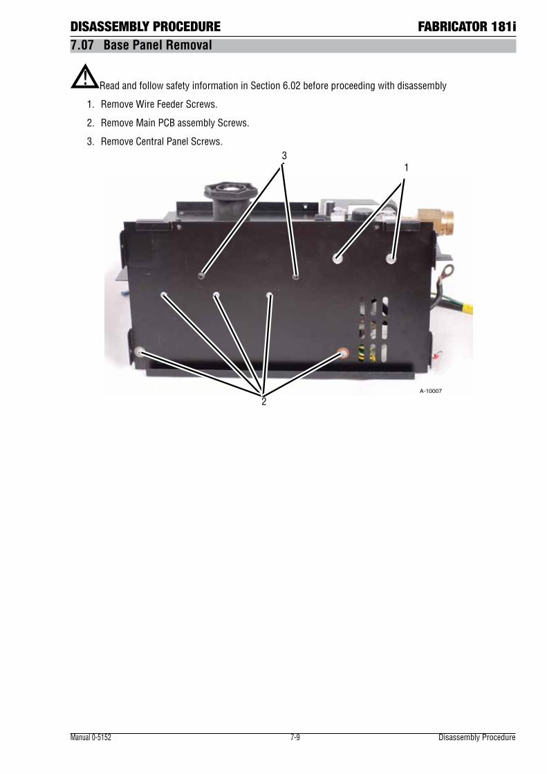
Manual 0-5152 7-9 Disassembly Procedure
DISASSEMBLY PROCEDURE FABRICATOR 181i7.07 Base Panel Removal
! Read and follow safety information in Section 6.02 before proceeding with disassembly
1. Remove Wire Feeder Screws.
2. Remove Main PCB assembly Screws.
3. Remove Central Panel Screws.
13
2A-10007

FABRICATOR 181i DISASSEMBLY PROCEDURE
Disassembly Procedure 7-10 Manual 0-5152
Notes
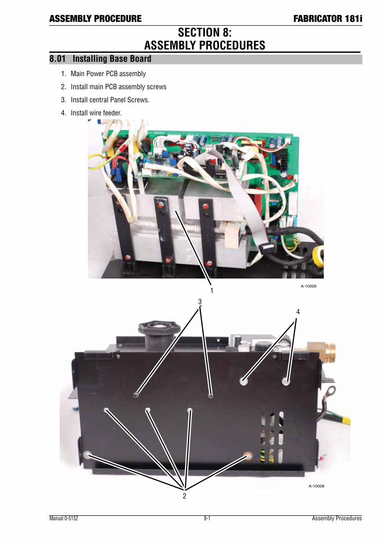
ASSEMBLY PROCEDURE FABRICATOR 181i
Manual 0-5152 8-1 Assembly Procedures
8.01 Installing Base Board
1. Main Power PCB assembly
2. Install main PCB assembly screws
3. Install central Panel Screws.
4. Install wire feeder.
1A-10009
43
2
A-10008
SECTION 8: ASSEMBLY PROCEDURES

Assembly Procedures 8-2 Manual 0-5152
FABRICATOR 181i ASSEMBLY PROCEDURES8.02 Installing Back Panel
1. Install gas inlet.
2. Install ON/OFF switch
3. Install wire cord and 2 screws.
4. Reconnect Input Wire on the ON/OFF switch.
5. Reinstall Ferrite core onto Ground Wire.
6. Install fan.
7. Reconnect power ON/OFF switch to terminals on Main Power PCB.
8. Reconnect Ground Wire to filter PCB.
9. Reconnect Rear Panel screws.
6
5
3
A-10116
14
2
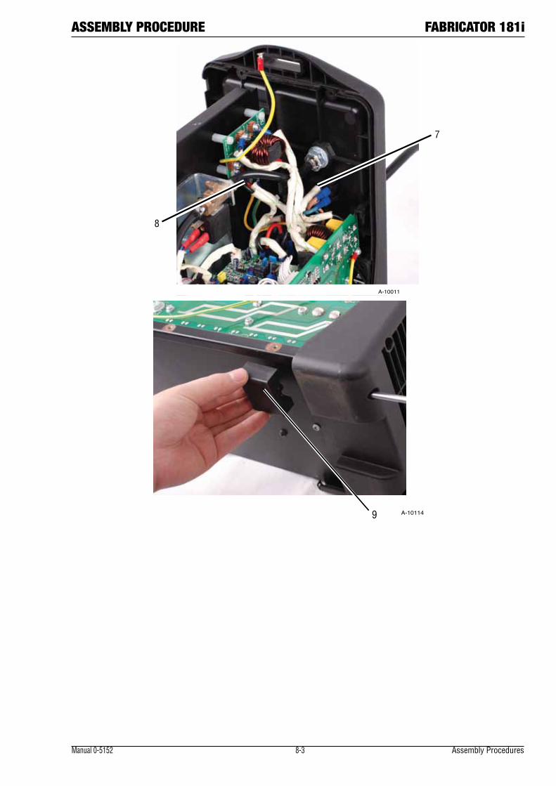
ASSEMBLY PROCEDURE FABRICATOR 181i
Manual 0-5152 8-3 Assembly Procedures
8
7
A-10011
9 A-10114
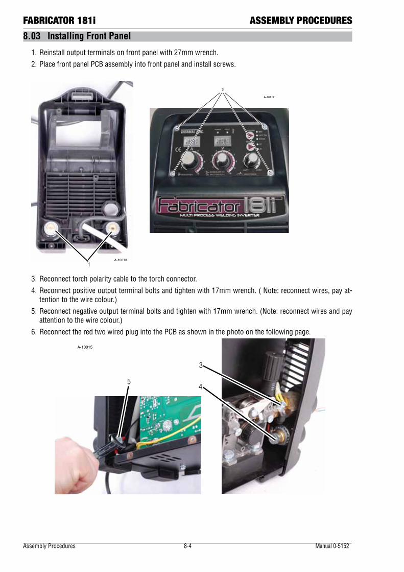
Assembly Procedures 8-4 Manual 0-5152
FABRICATOR 181i ASSEMBLY PROCEDURES
8.03 Installing Front Panel
1. Reinstall output terminals on front panel with 27mm wrench.
2. Place front panel PCB assembly into front panel and install screws.
1A-10013
2
A-10000
A-10117
3. Reconnect torch polarity cable to the torch connector.
4. Reconnect positive output terminal bolts and tighten with 17mm wrench. ( Note: reconnect wires, pay at-tention to the wire colour.)
5. Reconnect negative output terminal bolts and tighten with 17mm wrench. (Note: reconnect wires and pay attention to the wire colour.)
6. Reconnect the red two wired plug into the PCB as shown in the photo on the following page.
5
3
4
A-10015
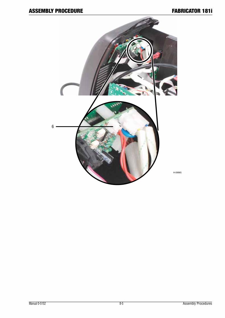
ASSEMBLY PROCEDURE FABRICATOR 181i
Manual 0-5152 8-5 Assembly Procedures
A-09965
6
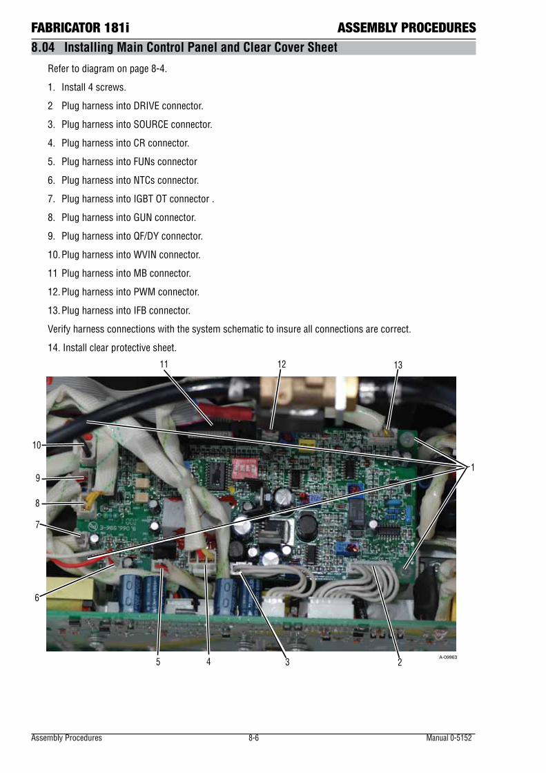
Assembly Procedures 8-6 Manual 0-5152
FABRICATOR 181i ASSEMBLY PROCEDURES8.04 Installing Main Control Panel and Clear Cover Sheet
Refer to diagram on page 8-4.
1. Install 4 screws.
2 Plug harness into DRIVE connector.
3. Plug harness into SOURCE connector.
4. Plug harness into CR connector.
5. Plug harness into FUNs connector
6. Plug harness into NTCs connector.
7. Plug harness into IGBT OT connector .
8. Plug harness into GUN connector.
9. Plug harness into QF/DY connector.
10. Plug harness into WVIN connector.
11 Plug harness into MB connector.
12. Plug harness into PWM connector.
13. Plug harness into IFB connector.
Verify harness connections with the system schematic to insure all connections are correct.
14. Install clear protective sheet.
1
5 4 3 2
6
13
7
8
9
12 11
10
A-09963
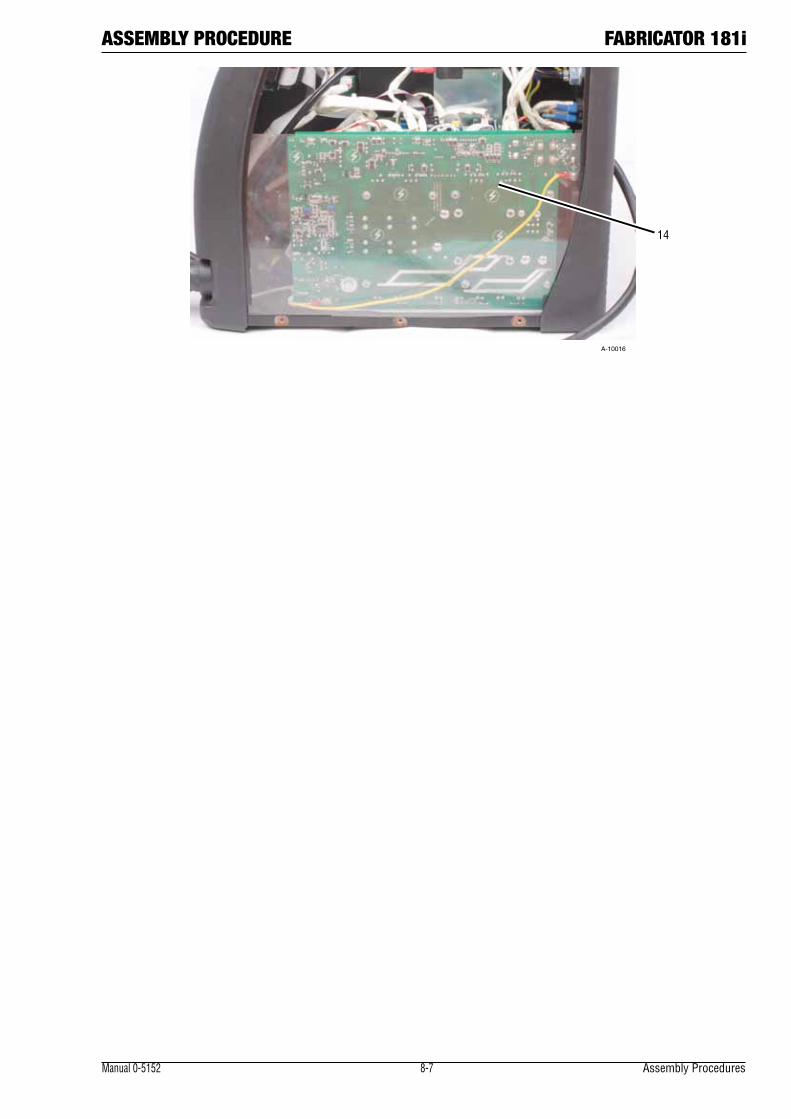
ASSEMBLY PROCEDURE FABRICATOR 181i
Manual 0-5152 8-7 Assembly Procedures
14
A-10016
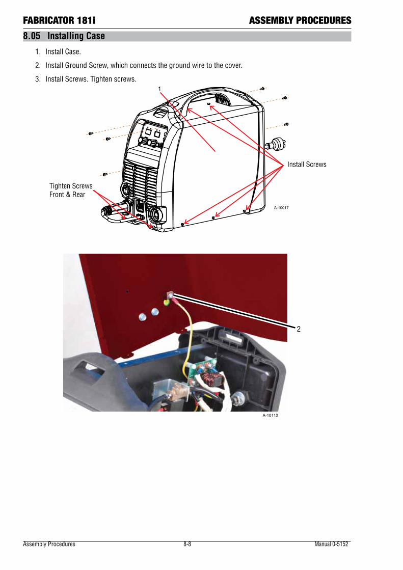
Assembly Procedures 8-8 Manual 0-5152
FABRICATOR 181i ASSEMBLY PROCEDURES
8.05 Installing Case
1. Install Case.
2. Install Ground Screw, which connects the ground wire to the cover.
3. Install Screws. Tighten screws.
Tighten Screws Front & Rear
Install Screws
1
A-10017
2
A-10112
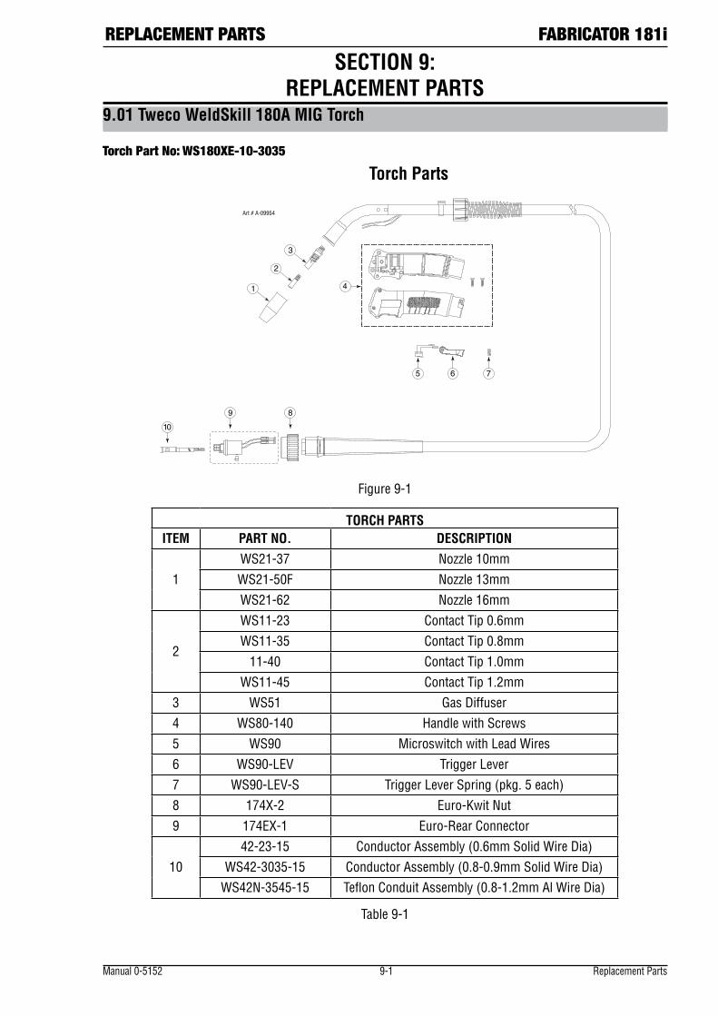
REPLACEMENT PARTS FABRICATOR 181i
Manual 0-5152 9-1 Replacement Parts
SECTION 9: REPLACEMENT PARTS
9.01 Tweco WeldSkill 180A MIG Torch
Torch Part No: WS180XE-10-3035
Torch Parts
Art # A-09954
Figure 9-1
TORCH PARTSITEM PART NO. DESCRIPTION
1WS21-37 Nozzle 10mmWS21-50F Nozzle 13mmWS21-62 Nozzle 16mm
2
WS11-23 Contact Tip 0.6mmWS11-35 Contact Tip 0.8mm
11-40 Contact Tip 1.0mmWS11-45 Contact Tip 1.2mm
3 WS51 Gas Diffuser4 WS80-140 Handle with Screws5 WS90 Microswitch with Lead Wires6 WS90-LEV Trigger Lever7 WS90-LEV-S Trigger Lever Spring (pkg. 5 each)8 174X-2 Euro-Kwit Nut9 174EX-1 Euro-Rear Connector
1042-23-15 Conductor Assembly (0.6mm Solid Wire Dia)
WS42-3035-15 Conductor Assembly (0.8-0.9mm Solid Wire Dia)WS42N-3545-15 Teflon Conduit Assembly (0.8-1.2mm Al Wire Dia)
Table 9-1
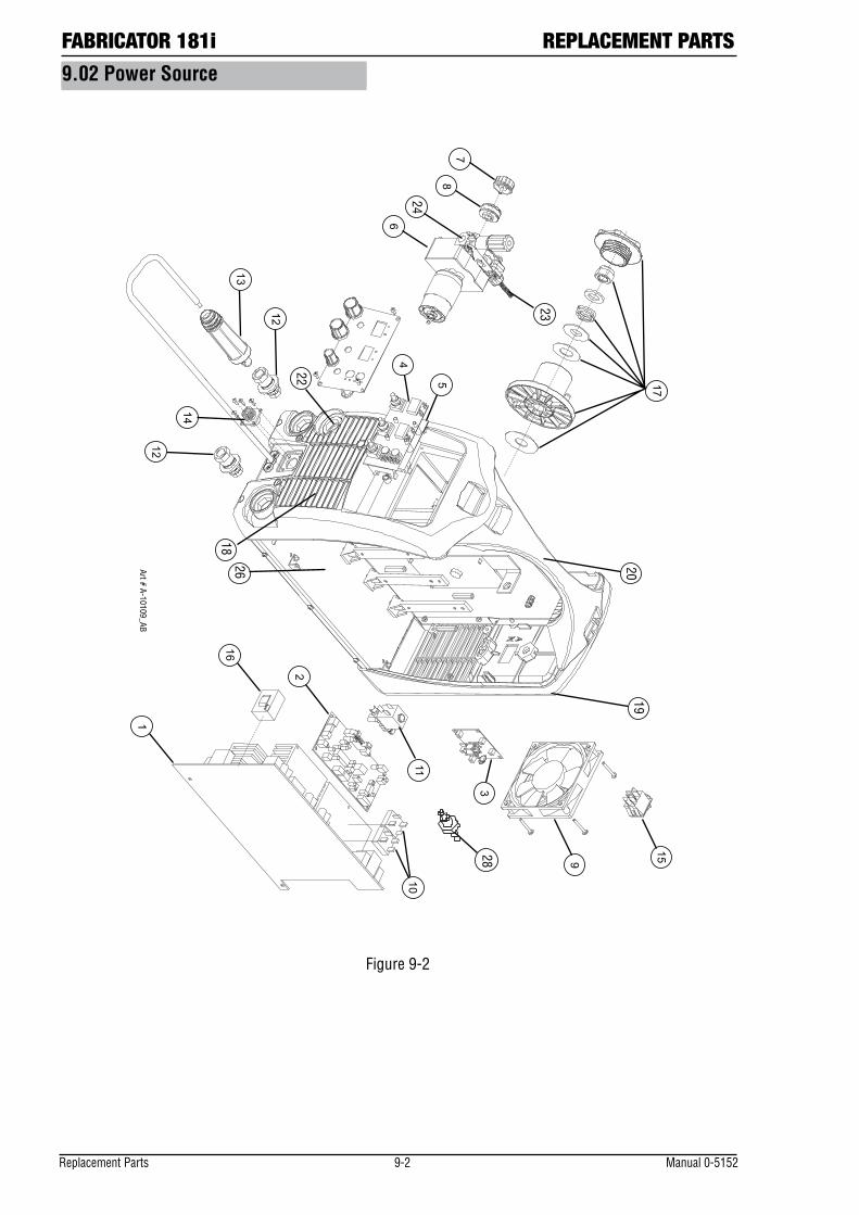
FABRICATOR 181i REPLACEMENT PARTS
Replacement Parts 9-2 Manual 0-5152
18
1920
22
26
23
24
28
Art # A-10109_AB
9.02 Power Source
Figure 9-2
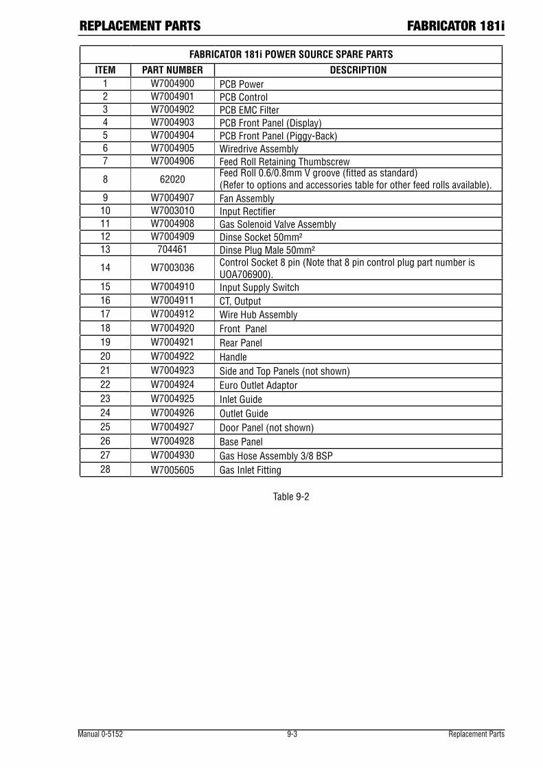
REPLACEMENT PARTS FABRICATOR 181i
Manual 0-5152 9-3 Replacement Parts
FABRICATOR 181i POWER SOURCE SPARE PARTS
ITEM PART NUMBER DESCRIPTION1 W7004900 PCB Power2 W7004901 PCB Control3 W7004902 PCB EMC Filter4 W7004903 PCB Front Panel (Display)5 W7004904 PCB Front Panel (Piggy-Back)6 W7004905 Wiredrive Assembly7 W7004906 Feed Roll Retaining Thumbscrew
8 62020Feed Roll 0.6/0.8mm V groove (fitted as standard) (Refer to options and accessories table for other feed rolls available).
9 W7004907 Fan Assembly10 W7003010 Input Rectifier11 W7004908 Gas Solenoid Valve Assembly12 W7004909 Dinse Socket 50mm²13 704461 Dinse Plug Male 50mm²
14 W7003036 Control Socket 8 pin (Note that 8 pin control plug part number is UOA706900).
15 W7004910 Input Supply Switch16 W7004911 CT, Output17 W7004912 Wire Hub Assembly18 W7004920 Front Panel19 W7004921 Rear Panel20 W7004922 Handle21 W7004923 Side and Top Panels (not shown)22 W7004924 Euro Outlet Adaptor23 W7004925 Inlet Guide24 W7004926 Outlet Guide25 W7004927 Door Panel (not shown)26 W7004928 Base Panel27 W7004930 Gas Hose Assembly 3/8 BSP28 W7005605 Gas Inlet Fitting
Table 9-2

FABRICATOR 181i REPLACEMENT PARTS
Replacement Parts 9-4 Manual 0-5152
Notes

OPTIONS AND ACCESSORIES FABRICATOR 181i
Manual 0-5152 10-1 Accessories
SECTION 10: OPTIONS AND ACCESSORIES
10.01 Options and Accessories
DESCRIPTION PART NUMBER
Tweco WeldSkill 180A MIG Torch with 3M lead WS180XE-10-3035
TIG Torch 17V with 4m lead 310.050.002
Feed Roll 0.6/0.8mm V groove (hard), (fitted) 62020
Feed Roll 0.9/1.2mm V groove (hard) 62022
Feed Roll 0.8/0.9mm U groove (soft) 62179
Feed Roll 1.0/1.2mm U groove (soft) 62024
Feed Roll 0.8/0.9mm V knurled (flux cored) 62028Table 10-1: Fabricator 181i Options and Accessories List

THERMAL ARC - LIMITED WARRANTY TERMS
LIMITED WARRANTY: Thermal Arc ®, Inc, A Thermadyne Company, hereafter, “Thermal Arc” warrants to cus-tomers of its authorized distributors hereafter “Purchaser” that its products will be free of defects in workman-ship or material. Should any failure to conform to this warranty appear within the time period applicable to the Thermal Arc products as stated below, Thermal Arc shall, upon notification thereof and substantiation that the product has been stored, installed, operated, and maintained in accordance with Thermal Arc’s specifications, instructions, recommendations and recognized standard industry practice, and not subject to misuse, repair, neglect, alteration, or accident, correct such defects by suitable repair or replacement, at Thermal Arc’s sole option, of any components or parts of the product determined by Thermal Arc to be defective.
THERMAL ARC MAKES NO OTHER WARRANTY, EXPRESS OR IMPLIED. THIS WARRANTY IS EXCLUSIVE AND IN LIEU OF ALL OTHERS, INCLUDING, BUT NOT LIMITED TO ANY WARRANTY OF MERCHANTABILITY OR FITNESS FOR ANY PARTICULAR PURPOSE.
LIMITATION OF LIABILITY: THERMAL ARC SHALL NOT UNDER ANY CIRCUMSTANCES BE LIABLE FOR SPECIAL, INDIRECT OR CONSEQUENTIAL DAMAGES, SUCH AS, BUT NOT LIMITED TO, LOST PROFITS AND BUSINESS INTERRUPTION. The remedies of the Purchaser set forth herein are exclusive and the liability of Thermal Arc with respect to any contract, or anything done in connection therewith such as the performance or breach thereof, or from the manufacture, sale, delivery, resale, or use of any goods covered by or furnished by Thermal Arc whether arising out of contract, negligence, strict tort, or under any warranty, or otherwise, shall not, except as expressly provided herein, exceed the price of the goods upon which such liability is based. No employee, agent, or representative of Thermal Arc is authorized to change this warranty in any way or grant any other warranty.
PURCHASER’S RIGHTS UNDER THIS WARRANTY ARE VOID IF REPLACEMENT PARTS OR ACCESSORIES ARE USED WHICH IN THERMAL ARC’S SOLE JUDGEMENT MAY IMPAIR THE SAFETY OR PERFORMANCE OF ANY THERMAL ARC PRODUCT. PURCHASER’S RIGHTS UNDER THIS WARRANTY ARE VOID IF THE PRODUCT IS SOLD TO PURCHASER BY NON-AUTHORIZED PERSONS.
The warranty is effective for the time stated below beginning on the date that the authorized distributor delivers the products to the Purchaser. Notwithstanding the foregoing, in no event shall the warranty period extend more than the time stated plus one year from the date Thermal Arc delivered the product to the authorized distributor.

TERMS OF WARRANTY – JANUARY 2011
In accordance with the warranty periods stated below, Thermadyne guarantees the proposed product to be free from defects in material or workmanship when operated in accordance with the written instructions as defined in this operating manual.
Thermadyne welding products are manufactured for use by commercial and industrial users and trained per-sonnel with experience in the use and maintenance of electrical welding and cutting equipment.
Thermadyne will repair or replace, at its discretion, any warranted parts or components that fail due to defects in material or workmanship within the warranty period. The warranty period begins on the date of sale to the end user.
Thermal Arc Fabricator 181i
Component Warranty PeriodPower Source 2 YearsMIG Torch, Electrode Holder / Lead & Work Lead 3 MonthsMIG Torch Consumables NIL
If warranty is being sought, Please contact your Thermadyne product supplier for the warranty repair procedure.
Thermadyne warranty will not apply to:
• EquipmentthathasbeenmodifiedbyanyotherpartyotherthanThermadyne’sownservicepersonnelorwith prior written consent obtained from Thermadyne Service Department.
• Equipmentthathasbeenusedbeyondthespecificationsestablishedintheoperatingmanual.
• Installationnotinaccordancewiththeinstallation/operatingmanual.
• Anyproductthathasbeensubjectedtoabuse,misuse,negligenceoraccident.
• Failuretocleanandmaintain(includinglackoflubrication,maintenanceandprotection),themachineasset forth in the operating, installation or service manual.
Within this operating manual are details regarding the maintenance necessary to ensure trouble free operation.
This manual also offers basic troubleshooting, operational and technical details including application usage.
You may also wish to visit our web site www.thermadyne.com select your product class and then select lit-erature. Here you will find documentation including:
• Operatormanuals
• Servicemanuals
• Productguides
Alternatively please contact your Thermadyne distributor and speak with a technical representative.
NOTE
Warranty repairs must be performed by either a Thermadyne Service Centre, a Thermadyne distributor or an Authorised Service Agent approved by the Company.

W O R L D H E A D Q U A R T E R S : 16052 S w i n g l e y R i d g e R o a d , S u i t e 3 0 0 • S t . Lou i s , M i s s o u r i 63017 U . S . A .
A Global Cutting & Welding Market Leader™
Customer Care UK: +44 (0)1257 261 755 / Fax: +44 (0)1257 224 800Customer Care Italy +39 02 36546801 / Fax: +39 02 36546480
www.thermadyne.com
Denton, TX USAU.S. Customer CarePh: 1-800-426-1888 (tollfree)Fax: 1-800-535-0557 (tollfree)International Customer CarePh: 1-940-381-1212Fax: 1-940-483-8178
Miami, FL USASales Office, Latin America Ph: 1-954-727-8371Fax: 1-954-727-8376
Oakville, Ontario, CanadaCanada Customer CarePh: 1-905-827-4515Fax: 1-800-588-1714 (tollfree)
Chorley, United KingdomCustomer CarePh: +44 1257-261755Fax: +44 1257-224800
Milan, ItalyCustomer CarePh: +39 0236546801Fax: +39 0236546840
Cikarang, IndonesiaCustomer CarePh: 6221-8990-6095Fax: 6221-8990-6096
Rawang, MalaysiaCustomer CarePh: +603 6092-2988Fax: +603 6092-1085
Melbourne, AustraliaAustralia Customer CarePh: 1300-654-674 (tollfree)Ph: 61-3-9474-7400 Fax: 61-3-9474-7391InternationalPh: 61-3-9474-7508Fax: 61-3-9474-7488
Shanghai, ChinaSales OfficePh: +86 21-64072626Fax: +86 21-64483032
SingaporeSales OfficePh: +65 6832-8066Fax: +65 6763-5812
Form No. 0-5152AB (06-Apr-2012) © 2011 Thermadyne Industries, Inc. www.thermadyne.com Printed in China
THE AMERICAS EUROPE ASIA/PACIFIC