
Kim, Sun-Yong, M.D. Department of Radiology Ajou University Hospital, Suwon, Korea

1792 IEEE TRANSACTIONS ON CIRCUITS AND SYSTEMS FOR VIDEO TECHNOLOGY, VOL. 22, NO. 12, DECEMBER 2012
Intra Coding of the HEVC StandardJani Lainema, Frank Bossen, Member, IEEE, Woo-Jin Han, Member, IEEE, Junghye Min, and Kemal Ugur
Abstract—This paper provides an overview of the intra codingtechniques in the High Efficiency Video Coding (HEVC) standardbeing developed by the Joint Collaborative Team on Video Coding(JCT-VC). The intra coding framework of HEVC follows that oftraditional hybrid codecs and is built on spatial sample predictionfollowed by transform coding and postprocessing steps. Novelfeatures contributing to the increased compression efficiencyinclude a quadtree-based variable block size coding structure,block-size agnostic angular and planar prediction, adaptivepre- and postfiltering, and prediction direction-based transformcoefficient scanning. This paper discusses the design principlesapplied during the development of the new intra coding methodsand analyzes the compression performance of the individual tools.Computational complexity of the introduced intra predictionalgorithms is analyzed both by deriving operational cycle countsand benchmarking an optimized implementation. Using objectivemetrics, the bitrate reduction provided by the HEVC intra codingover the H.264/advanced video coding reference is reported to be22% on average and up to 36%. Significant subjective picturequality improvements are also reported when comparing theresulting pictures at fixed bitrate.
Index Terms—High Efficiency Video Coding (HEVC), imagecoding, intra prediction, Joint Collaborative Team on VideoCoding (JCT-VC), video coding.
I. Introduction
THE TWO prominent international organizations specify-ing video coding standards, namely ITU-T Video Coding
Experts Group (VCEG) and ISO/IEC Moving Picture ExpertsGroup (MPEG), formed the Joint Collaborative Team on VideoCoding (JCT-VC) in April 2010. Since then, JCT-VC hasbeen working toward defining a next-generation video codingstandard called High Efficiency Video Coding (HEVC). Thereare two major goals for this standard. First, it is targeted toachieve significant improvements in coding efficiency com-pared to H.264/Advanced Video Coding (AVC) [1], especiallywhen operating on high-resolution video content. Second, thestandard should have low enough complexity to enable high-resolution high-quality video applications in various use cases,
Manuscript received April 13, 2012; revised July 18, 2012; accepted August21, 2012. Date of publication October 2, 2012; date of current version January8, 2013. This work was supported by Gachon University under the ResearchFund of 2012 GCU-2011-R288. This paper was recommended by AssociateEditor O. C. Au. (Corresponding author: W.-J. Han.)
J. Lainema and K. Ugur are with the Nokia Research Center, Tampere33720, Finland (e-mail: [email protected]; [email protected]).
F. Bossen is with DOCOMO Innovations, Inc., Palo Alto, CA 94304 USA(e-mail: [email protected]).
W.-J. Han is with Gachon University, Seongnam 461-701, Korea (e-mail:[email protected]).
J. Min is with Samsung Electronics, Suwon 442-742, Korea (e-mail:[email protected]).
Color versions of one or more of the figures in this paper are availableonline at http://ieeexplore.ieee.org.
Digital Object Identifier 10.1109/TCSVT.2012.2221525
including operation in mobile environments with tablets andmobile phones.
This paper analyzes different aspects of the HEVC intracoding process and discusses the motivation leading to theselected design. The analysis includes assessing codingefficiency of the individual tools contributing to the overallperformance as well as studying complexity of the introducednew algorithms in detail. This paper also describes themethods HEVC utilizes to indicate the selected intra codingmodes and further explains how the tools are integrated withthe HEVC coding block architecture.
Intra coding in HEVC can be considered as an extension ofH.264/AVC, as both approaches are based on spatial sampleprediction followed by transform coding. The basic elementsin the HEVC intra coding design include:
1) quadtree-based coding structure following the HEVCblock coding architecture;
2) angular prediction with 33 prediction directions;3) planar prediction to generate smooth sample surfaces;4) adaptive smoothing of the reference samples;5) filtering of the prediction block boundary samples;6) prediction mode-dependent residual transform and coef-
ficient scanning;7) intra mode coding based on contextual information.
In addition, the HEVC intra coding process shares severalprocessing steps with HEVC inter coding. This processing,including, e.g., transformation, quantization, entropy coding,reduction of blocking effects, and applying sample adaptiveoffsets (SAO), is outside of the scope of this paper.
This paper is organized as follows. Section II explains themotivation leading to the selected design for HEVC intracoding. It also describes the overall HEVC coding architectureand the new intra prediction tools introduced in the HEVCstandard. Section III presents the intra mode coding andthe residual coding approaches of the standard. Section IVprovides complexity analysis of the introduced intra predictionprocesses with detailed information about the contribution ofdifferent intra prediction modes. Section V summarizes thecompression efficiency gains provided by the proposed designand Section VI concludes this paper.
II. HEVC Intra Coding Architecture
In H.264/AVC, intra coding is based on spatial extrapolationof samples from previously decoded image blocks, followedby discrete cosine transform (DCT)-based transform coding[2]. HEVC utilizes the same principle, but further extends itto be able to efficiently represent wider range of textural and
1051-8215/$31.00 c© 2012 IEEE

LAINEMA et al.: INTRA CODING OF THE HEVC STANDARD 1793
structural information in images. The following aspects wereconsidered during the course of HEVC project leading to theselected intra coding design.
1) Range of supported coding block sizes: H.264/AVCsupports intra coded blocks up to the size of 16 × 16pixels. This represents a very small area in a high-definition picture and is not large enough to efficientlyrepresent certain textures.
2) Prediction of directional structures: H.264/AVC sup-ports up to eight directional intra prediction modes fora given block. This number is not adequate to predictaccurately directional structures present in typical videoand image content, especially when larger block sizesare used.
3) Prediction of homogeneous regions: The plane mode ofH.264/AVC was designed to code homogeneous imageregions. However, this mode does not guarantee con-tinuity at block boundaries, which can create visibleartifacts. Thus, a mode that guarantees continuous pre-diction sample surfaces would be desired.
4) Consistency across block sizes: H.264/AVC uses differ-ent methods to predict a block depending on the size ofthe block and the color component the block represents.A more consistent design is preferred, especially asHEVC supports a large variety of block sizes.
5) Transforms for intra coding: H.264/AVC utilizes a fixedDCT transform for a given block size. This design doesnot take into consideration different statistics of the pre-diction error along the horizontal and vertical directionsdepending on the directionality of the prediction.
6) Intra mode coding: Due to the substantially increasednumber of intra modes, more efficient coding techniquesare required for mode coding.
The coding structure utilized for intra coding in HEVCfollows closely the overall architecture of the codec. Imagesare split into segments called coding units (CU), predic-tion units (PU), and transform units (TU). CU representquadtree split regions that are used to separate the intra andinter coded blocks. Inside a CU, multiple nonoverlappingPU can be defined, each of which specifies a region withindividual prediction parameters. CU are further split into aquadtree of transform units, each TU having a possibilityof applying residual coding with a transform of the size ofthe TU.
HEVC contains several elements improving the efficiency ofintra prediction over earlier solutions. The introduced methodscan model accurately different directional structures as wellas smooth regions with gradually changing sample values.There is also emphasis on avoiding introduction of artificialedges with potential blocking effects. This is achieved byadaptive smoothing of the reference samples and smoothingthe generated prediction boundary samples for DC and directlyhorizontal and vertical modes.
All the prediction modes utilize the same basic set ofreference samples from above and to the left of the imageblock to be predicted. In the following sections, we denotethe reference samples by Rx,y with (x, y) having its originone pixel above and to the left of the block’s top-left corner.
Fig. 1. Reference samples Rx,y used in prediction to obtain predictedsamples Px,y for a block of size N × N samples.
TABLE I
Specification of Intra Prediction Modes and Associated Names
Intra Prediction Mode Associated Names0 Planar1 DC
2..34 Angular (N), N = 2...34
Similarly, Px,y is used to denote a predicted sample value ata position (x, y). Fig. 1 illustrates the notation used.
Neighboring reference samples may be unavailable for intraprediction, for example, at picture or slice boundaries, or atCU boundaries when constrained intra prediction is enabled.Missing reference samples on the left boundary are generatedby repetition from the closest available reference samplesbelow (or from above if no samples below are available).Similarly, the missing reference samples on the top boundaryare obtained by copying the closest available reference samplefrom the left. If no reference sample is available for intraprediction, all the samples are assigned a nominal averagesample value for a given bit depth (e.g., 128 for 8-b data).
It should be noted that in addition to left, above, andabove-right reconstructed samples used for H.264/AVC intraprediction, below-left side of samples (R0,N+1.. R0,2N ) arealso used for HEVC. These samples were excluded fromthe H.264/AVC process as they were rarely available in thetraditional macroblock-based coding structure [2], but thehierarchical HEVC coding architecture makes these candidatesavailable more frequently.
HEVC design supports a total of 35 intra prediction modes.Table I specifies the numbers and names associated with eachmode. In this paper, intra prediction mode 0 refers to the planarintra prediction, mode 1 to DC prediction, and modes 2 to34 to angular prediction modes with different directionalities.Fig. 2 further illustrates the prediction directions associatedwith the angular modes.
A. Angular Intra Prediction
Angular intra prediction in HEVC is designed to be ableto efficiently model different directional structures typically

1794 IEEE TRANSACTIONS ON CIRCUITS AND SYSTEMS FOR VIDEO TECHNOLOGY, VOL. 22, NO. 12, DECEMBER 2012
Fig. 2. HEVC angular intra prediction modes numbered from 2 to 34 andthe associated displacement parameters. H and V are used to indicate thehorizontal and vertical directionalities, respectively, while the numeric part ofthe identifier refers to the pixels’ displacement as 1/32 pixel fractions.
present in video and image contents. The number and angu-larity of prediction directions are selected to provide a goodtradeoff between encoding complexity and coding efficiencyfor typical video material. The sample prediction process itselfis designed to have low computational requirements and to beconsistent across block sizes and prediction directions. Thelatter aims at minimizing the silicon area in hardware andthe amount of code in software implementations. It is alsointended to make it easier to optimize the implementationfor high performance and throughput in various environments.This is especially important as the number of block sizesand prediction directions supported by HEVC intra coding farexceeds those of previous video codecs, such as H.264/AVC.In HEVC, there are four effective intra prediction block sizesranging from 4 × 4 to 32 × 32 samples, each of which supports33 distinct prediction directions. A decoder must thus support132 combinations of block size and prediction direction.
The following sections discuss in further detail differentaspects contributing to the coding performance and implemen-tation complexity of the HEVC angular intra prediction.
1) Angle Definitions: In natural imagery, horizontal andvertical patterns typically occur more frequently than patternswith other directionalities. The set of 33 prediction anglesis defined to optimize the prediction accuracy based on thisobservation [7]. Eight angles are defined for each octant withassociated displacement parameters, as shown in Fig. 2.
Small displacement parameters for modes close to horizon-tal and vertical directions provide more accurate predictionfor nearly horizontal and vertical patterns. The displacementparameter differences become larger when getting closer todiagonal directions to reduce the density of prediction modesfor less frequently occurring patterns.
Fig. 3. Example of projecting left reference samples to extend the topreference row. The bold arrow represents the prediction direction and thethin arrows the reference sample projections in the case of intra mode 23(vertical prediction with a displacement of −9/32 pixels per row).
2) Reference Pixel Handling: The intra sample predictionprocess in HEVC is performed by extrapolating sample valuesfrom the reconstructed reference samples utilizing a givendirectionality. In order to simplify the process, all samplelocations within one prediction block are projected to a singlereference row or column depending on the directionality of theselected prediction mode (utilizing the left reference columnfor angular modes 2 to 17 and the above reference row forangular modes 18 to 34).
In some cases, the projected pixel locations would havenegative indexes. In these cases, the reference row or column isextended by projecting the left reference column to extend thetop reference row toward left, or projecting the top referencerow to extend the left reference column upward in thecase of vertical and horizontal predictions, respectively. Thisapproach was found to have a negligible effect on compressionperformance, and has lower complexity than an alternativeapproach of utilizing both top and left references selectivelyduring the prediction sample generation process [5]. Fig. 3depicts the process for extending the top reference row withsamples from the left reference columns for an 8 × 8 block ofpixels.
3) Sample Prediction for Arbitrary Number of Directions:Each predicted sample Px,y is obtained by projecting itslocation to a reference row of pixels applying the selectedprediction direction and interpolating a value for the sampleat 1/32 pixel accuracy. Interpolation is performed linearlyutilizing the two closest reference samples
Px,y =((
32 − wy
) · Ri,0 + wy · Ri+1,0 + 16)
>> 5 (1)
where wy is the weighting between the two reference samplescorresponding to the projected subpixel location in betweenRi,0 and Ri+1,0, and >> denotes a bit shift operation tothe right. Reference sample index i and weighting parameterwy are calculated based on the projection displacement dassociated with the selected prediction direction (describingthe tangent of the prediction direction in units of 1/32 samples

LAINEMA et al.: INTRA CODING OF THE HEVC STANDARD 1795
and having a value from −32 to +32 as shown in Fig. 2) as
cy = (y · d) >> 5wy = (y · d) &31i = x + cy
(2)
where & denotes a bitwise AND operation. It should be notedthat parameters cy and wy depend only on the coordinate y andthe selected prediction displacement d. Thus, both parametersremain constant when calculating predictions for one line ofsamples and only (1) needs to be evaluated per sample basis.When the projection points to integer samples (i.e., when wy
equals zero), the process is even simpler and consists of onlycopying integer reference samples from the reference row.
Equations (1) and (2) define how the predicted samplevalues are obtained in the case of vertical prediction (modes18 to 34) when the reference row above the block is used toderive the prediction. Prediction from the left reference column(modes 2 to 17) is derived identically by swapping the x andy coordinates in (1) and (2).
B. Planar Prediction
While providing good prediction in the presence of edgesis important, not all image content fits an edge model. TheDC prediction provides an alternative but is only a coarseapproximation as the prediction is of order 0. H.264/AVCfeatures an order-1 plane prediction mode that derives abilinear model for a block using the reference samples andgenerates the prediction using this model. One disadvantageof this method is that it may introduce discontinuities alongthe block boundaries. The planar prediction mode defined inHEVC aims to replicate the benefits of the plane mode whilepreserving continuities along block boundaries. It is essentiallydefined as an average of two linear predictions (see [8, Fig. 2]for a graphical representation)
PVx,y = (N − y) · Rx,0 + y · R0,N+1
PHx,y = (N − x) · R0,y + x · RN+1,0
Px,y =(PV
x,y + PHx,y + N
)>>
(log2 (N) + 1
).
(3)
C. Reference Sample Smoothing
H.264/AVC applies a three-tap smoothing filter to the ref-erence samples when predicting 8 × 8 luma blocks. HEVCuses the same smoothing filter ([1 2 1]/4) for blocks of size8 × 8 and larger. The filtering operation is applied for eachreference sample using neighboring reference samples. Thefirst reference sample R0,2N and R2N,0 are not filtered. For32 × 32 blocks, all angular modes except horizontal andvertical use a filtered reference. In 16 × 16 blocks, the modesnot using a filtered reference are extended to the four modes(9, 11, 25, 27) closest to horizontal and vertical. Smoothingis also applied where the planar mode is used, for block sizes8 × 8 and larger. However, HEVC is more discerning in the useof this smoothing filter for smaller blocks. For 8 × 8 blocks,only the diagonal modes (2, 18, 34) use a filtered reference.Applying the reference sample smoothing selectively based onthe block size and directionality of the prediction is reportedto reduce contouring artifacts caused by edges in the referencesample arrays [23].
D. Boundary Smoothing
As noted above in the case of the H.264/AVC plane predic-tion mode, DC and angular prediction modes may introducediscontinuities along block boundaries. To remedy this prob-lem, the first prediction row and column are filtered in thecase of DC prediction with a two-tap finite impulse responsefilter (corner sample with a three-tap filter). Similarly, the firstprediction column for directly vertical prediction and the firstprediction row for directly horizontal prediction are filteredutilizing a gradient-based smoothing [9]. For a more completedescription of the filtering process, please refer to [25].
As the prediction for chroma components tends to be verysmooth, the benefits of the boundary smoothing would belimited. Thus, in order to avoid extra processing with marginalquality improvements, the prediction boundary smoothing isonly applied to luma component. The average coding effi-ciency improvement provided by the boundary smoothing ismeasured to be 0.4% in HM 6.0 environment [14].
E. I − PCM Mode and Transform Skipping Mode
HEVC supports two special coding modes for intra codingdenoted as I−PCM and transform skipping mode. In I−PCMmode, prediction, transform, quantization, and entropy codingare bypassed while the prediction samples are coded by apredefined number of bits. The main purpose of the I−PCMmode is to handle the situation when the signal cannot beefficiently coded by other modes.
On the contrary, only transform is bypassed in transformskipping mode. It was adopted to improve the coding effi-ciency for specific video contents such as computer-generatedgraphics. HEVC restricts the use of this mode when the blocksize is equal to 4 × 4 to avoid the significant design changedue to this mode while this choice was proven to have mostof coding efficiency benefits.
F. Restrictions for Partitioning Types
HEVC intra coding supports two types of PU division,PART−2N × 2N and PART−N × N, splitting a CU intoone or four equal-size PUs, respectively. However, the fourregions specified by the partitioning type PART−N × N canbe also represented by four smaller CU with the partitioningtype PART−2N × 2N. Due to this, HEVC allows an intraCU to be split into four PU only at the minimum CU size.It has been demonstrated that this restriction is associatedwith minimal impact in coding efficiency, but it reduces theencoding complexity significantly [3].
Another way to achieve the same purpose would be reducingthe CU size to 4 × 4 with the partitioning mode PART−2N ×2N. However, this approach would result in a chroma intraprediction block size of 2 × 2 pixels, which can be critical tothe throughput of the entire intra prediction process. For thisreason, the minimum allowed CU size is restricted to 8 × 8pixels while allowing the partitioning type PART−N × N onlyin the smallest CU.
G. TU-Based Prediction
When a CU is split into multiple TU, the intra predictionis applied for each TU sequentially instead of applying the

1796 IEEE TRANSACTIONS ON CIRCUITS AND SYSTEMS FOR VIDEO TECHNOLOGY, VOL. 22, NO. 12, DECEMBER 2012
intra prediction at the PU level. One obvious advantage forthis approach is the possibility of always utilizing the nearestneighboring reference samples from the already reconstructedTU. It has been shown that this property improves the intrapicture coding efficiency by about 1.2% [4] compared to thecase of using PU border reference samples for the PU. Itshould be noted that all the intra prediction information isindicated per PU and the TUs inside the same PU share thesame intra prediction mode.
III. Mode and Residual Coding
A. Mode Coding for Luma
HEVC supports total 33 angular prediction modes as well asplanar and DC prediction for luma intra prediction for all thePU sizes. Due to the large number of intra prediction modes,H.264/AVC-like mode coding approach based on a single mostprobable mode was not found effective in HEVC [8]. Instead,HEVC defines three most probable modes for each PU basedon the modes of the neighboring PUs. The selected numberof most probable modes makes it also possible to indicateone of the 32 remaining modes by a fixed length code, asthe distribution of the mode probabilities outside of the set ofmost probable modes is found to be relatively uniform.
The selection of the set of three most probable modes isbased on modes of two neighboring PUs, one above and one tothe left of the current PU. By default, modes of both candidatePUs are included in the set. Possible duplicates and the thirdmode in the set are assigned with modes planar, DC, or angular(26) in this order. In the case that both top and left PU has thesame directional mode, that mode and two closest directionalmodes are used to construct the set of most probable modesinstead.
In the case current intra prediction mode is equal to one ofthe elements in the set of most probable modes, only the indexin the set is transmitted to the decoder. Otherwise, a 5-b fixedlength code is used to determine the selected mode outside ofthe set of most probable modes.
B. Derived Mode for Chroma Intra Prediction
Quite often structures in the chroma signal follow those ofthe luma. Taking advantage of this behavior, HEVC introducesa mechanism to indicate the cases when chroma PU utilizes thesame prediction mode as the corresponding luma PU. Table IIspecifies the mode arrangement used in signaling the chromamode.
In the case that derived mode is indicated for a PU, theprediction is performed by using the corresponding luma PUmode. In order to remove the possible redundancy in thesignaling arising when derived refers to one of the modesalways present, angular (34) mode is used to substitute theduplicate mode as shown in Table II.
C. Syntax Design for the Intra Mode Coding
HEVC uses three syntax elements to representthe luma intra prediction mode. The syntax elementprev−intra−luma−pred−flag specifies whether the luma intra
TABLE II
Specification of Chroma Intra Prediction
Modes and Associated Names
Chroma intra Alternative mode, ifprediction Primary mode primary mode is equal to
mode the derived mode0 Planar Angular (34)1 Angular (26) Angular (34)2 Angular (10) Angular (34)3 DC Angular (34)4 Derived N/A
prediction mode is matched with one of three most probablemodes. When the flag is equal to 1, the syntax elementmpm−idx is parsed, indicating which element of the mostprobable mode array specifies the luma intra predictionmode. When the flag is equal to 0, the syntax elementrem−intra−luma−pred−mode is parsed, specifying the lumaintra prediction mode as rem−intra−luma−pred−mode + N,where N is the number of elements in the most probablemode array having a mode index greater than or equal to thesyntax element rem−intra−luma−pred−mode.
In chroma mode coding, a 1-b syntax element (0) is assignedto the most often occurring derived mode, while 3-b syntaxelements (100, 101, 110, 111) are assigned to the remainingfour modes.
D. Intra Mode Residual Coding
HEVC utilizes intra mode dependent transforms and co-efficient scanning for coding the residual information. Thefollowing sections describe the selected approaches in moredetail.
1) Block Size-Dependent Transform Selection: Integer trans-forms derived from DCT and discrete sine transform (DST) areapplied to the intra residual blocks. A DST-based transform isselected for 4 × 4 luma blocks and DCT-based transforms forthe rest. For more details on the specification of the transforms,the reader is referred to [10] and [11].
Different approaches to select the transforms were studiedduring the course of the HEVC development. For example,an early HEVC draft utilized a method that selected thehorizontal and vertical transforms separately for 4 × 4 lumablocks based on the intra prediction mode. This approachprovided an average coding efficiency improvement of 0.8%[10]. However, it was found that the simple block size de-pended approach now adopted in the standard provides verysimilar coding efficiency [26]. Also larger size alternativetransforms were studied, but it was reported that the additionalcoding efficiency improvements were marginal compared tothe complexity impact [27]. Thus, only DCT-based transformsare utilized for block sizes larger than 4 × 4.
2) Intra Prediction Mode-Dependent Coefficient Scanning:HEVC applies adaptive scanning of transform coefficients tothe transform block sizes of 4 × 4 and 8 × 8 in orderto take advantage of the statistical distribution of the activecoefficients in 2-D transform blocks. The scan is selectedbased on directionality of the intra prediction mode as shown

LAINEMA et al.: INTRA CODING OF THE HEVC STANDARD 1797
TABLE III
Mapping Table Between Intra Prediction Modes and
Coefficient Scanning Order
IntraCoefficient Coefficient
prediction modescanning for scanning for
4 × 4 and 8 × 8 16 × 16 and 32 × 32Angular (6–14) Vertical DiagonalAngular (22–30) Horizontal DiagonalAll other modes Diagonal Diagonal
in Table III. Vertical and horizontal scans refer to the cor-responding raster scan orders, while the diagonal scan refersto a diagonal scan from down-left to up-right direction. Theaverage coding gain from the intra mode dependent scans isreportedly around 1.2% [12].
IV. Complexity of Intra Prediction Tools
A. Complexity Analysis of Decoding Process
1) Analysis of Operational Cycle Counts: Defining a propermetric for theoretical analysis of complexity can be difficultas various aspects come into play. For example, if relying oncounting operations, defining what constitutes one operationlargely depends on the underlying architecture. The bit widthof each data element being processed also plays an importantrole in determining a number of gates in hardware andthe amount of parallelism achievable in software. How analgorithm is implemented can also have a significant impact.A lower number of operations is not always better. Executingfour operations in parallel may be faster and considered lesscomplex than executing three in sequence. In this section, wethus limit ourselves to a more superficial comparison of HEVCprediction modes with the H.264/AVC ones.
The DC, directly horizontal, and directly vertical predic-tion modes are the ones most similar to those defined inH.264/AVC. HEVC simply defines an additional postfilteringoperation where one row and/or column of samples is filtered.The overhead of such filtering becomes less with larger blocksizes, as the fraction of filtered samples becomes smaller.
For predicting a block of size N × N, angular predictionrequires the computation of p = (u·a + v·b + 16) >> 5 foreach sample, which involves two multiplications (8-b unsignedoperands, 16-b result), two 16-b additions, and one 16-b shiftper predicted sample, for a total of five operations. In theH.264/AVC case, directional prediction may take the formp = (a + 2b + c + 2) >> 2, which may be considered to befive operations as well. However, on some architectures, thiscan be implemented using two 8-b halving add operations:d = (a + c) >> 1 and p = (d + b + 1) >> 1. TheH.264/AVC directional prediction process is thus less complexas it requires no multiplication and no intermediate value widerthan 9 b.
In the case of the plane and planar modes, consideringthe generating equations is probably not adequate, as theprediction values can be efficiently computed incrementally.For the H.264/AVC plane mode, it is expected that one 16-baddition, one 16-b shift, and one clip to 8-b range are required
TABLE IV
Decoding Time Comparison Between HM 6.0 Decoder and Its
Optimized Decoder Used for Further Analysis
SettingBitrate HM 6.0 Optimized
(Mbit/s) (s) (s)BasketballDrive, QP = 22 71.1 104.47 21.97BasketballDrive, QP = 37 8.4 61.60 6.98BQTerrace, QP = 22 179.2 163.94 41.42BQTerrace, QP = 37 21.6 91.00 12.03Cactus, QP = 22 105.7 120.46 28.84Cactus, QP = 37 14.2 69.59 8.78Kimono, QP = 22 22.3 37.11 7.02Kimono, QP = 37 3.8 26.94 2.88ParkScene, QP = 22 52.7 60.53 14.02ParkScene, QP = 37 7.3 33.90 4.35Geometric mean 25.4 66.34 10.91
Sequences are each 10-s long and are coded in intra-only mode. Optimizeddecoder is about four to nine times faster than HM.
per sample. For the HEVC planar mode, three 16-b additionsand one 16-b shift are expected per sample.
The partial analysis provided here is indicative. It suggeststhat the HEVC intra prediction modes are more complex thanthe AVC modes, but not necessarily by a large amount. In thefollowing, focus is shifted to complexity investigation basedon actual implementations.
2) Decoding Time of Intra Prediction in Relation to OverallDecoding Time: In a first experiment, the percentage of de-coding time spent on intra prediction is measured. Referenceencodings for the main profile of HM 6.0 [14] are used in theall-intra configuration [15]. The experiment is focused on high-definition sequences from the JCT-VC class B test set (five1920 × 1080 sequences). MD5 checksum computation andfile output of the reconstructed pictures are disabled such thatdecoding times more accurately reflect time spent on actuallydecoding pictures. Measurements are obtained on a laptopfeaturing an Intel Core i5 processor clocked at 2.53 GHz.Software was compiled using gcc 4.6.3. In addition to theHM software, an optimized decoder, based on [16], is alsoconsidered. Table IV summarizes decoding times and givesan indication of the level of optimization. For the comparativeresults between HEVC HM decoder and H.264/AVC JMdecoder, please refer to [24], which reported that they arecomparable. The fraction of decoding time used for intraprediction is further summarized in Table V.
While the results obtained with HM and optimized softwareshow some differences, they do not diverge significantly: onaverage roughly 12%–15% of decoding time is consumedby intra prediction. The results may however be somewhatsurprising in the sense that generating the reference arrays usedfor prediction takes more time than generating the predictionfrom those reference arrays. Part of this observation may becaused by the fact that in both of the tested software implemen-tations, full reference arrays are constructed, including 2N + 1samples for a row above and 2N +1 samples for a left column.Most prediction modes do not require all these samples, andconstructing only the required ones may reduce the amount oftime by up to 50%.
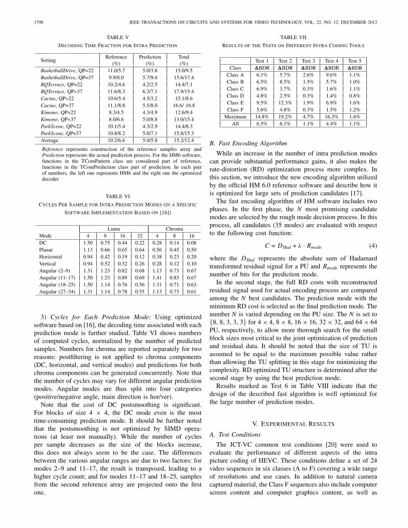
1798 IEEE TRANSACTIONS ON CIRCUITS AND SYSTEMS FOR VIDEO TECHNOLOGY, VOL. 22, NO. 12, DECEMBER 2012
TABLE V
Decoding Time Fraction for Intra Prediction
SettingReference Prediction Total
(%) (%) (%)BasketballDrive, QP=22 11.0/5.7 5.0/3.8 15.0/9.5BasketballDrive, QP=37 9.9/8.0 5.7/9.4 15.6/17.4BQTerrace, QP=22 10.2/4.6 4.2/2.5 14.4/7.1BQTerrace, QP=37 11.6/8.3 6.3/7.1 17.9/15.4Cactus, QP=22 10.6/5.4 4.5/3.2 15.1/8.6Cactus, QP=37 11.1/8.8 5.5/8.0 16.6/ 16.8Kimono, QP=22 8.3/4.5 4.3/4.9 12.6/9.4Kimono, QP=37 8.0/6.6 5.0/8.8 13.0/15.4ParkScene, QP=22 10.1/5.4 4.3/2.9 14.4/8.3ParkScene, QP=37 10.8/8.2 5.0/7.1 15.8/15.3Average 10.2/6.6 5.0/5.8 15.2/12.4
Reference represents construction of the reference samples array andPrediction represents the actual prediction process. For the HM6 software,functions in the TComPattern class are considered part of reference,functions in the TComPrediction class part of prediction. In each pairof numbers, the left one represents HM6 and the right one the optimizeddecoder
TABLE VI
Cycles Per Sample for Intra Prediction Modes (in a Specific
Software Implementation Based on [16])
Luma ChromaMode 4 8 16 32 4 8 16DC 1.50 0.75 0.44 0.22 0.28 0.14 0.08Planar 1.13 0.66 0.65 0.64 0.56 0.45 0.50Horizontal 0.94 0.42 0.19 0.12 0.38 0.23 0.20Vertical 0.94 0.52 0.32 0.26 0.28 0.12 0.10Angular (2–9) 1.31 1.23 0.82 0.68 1.13 0.73 0.67Angular (11–17) 1.50 1.23 0.89 0.69 1.41 0.83 0.67Angular (18–25) 1.50 1.14 0.76 0.56 1.31 0.71 0.63Angular (27–34) 1.31 1.14 0.78 0.55 1.13 0.73 0.61
3) Cycles for Each Prediction Mode: Using optimizedsoftware based on [16], the decoding time associated with eachprediction mode is further studied. Table VI shows numbersof computed cycles, normalized by the number of predictedsamples. Numbers for chroma are reported separately for tworeasons: postfiltering is not applied to chroma components(DC, horizontal, and vertical modes) and predictions for bothchroma components can be generated concurrently. Note thatthe number of cycles may vary for different angular predictionmodes. Angular modes are thus split into four categories(positive/negative angle, main direction is hor/ver).
Note that the cost of DC postsmoothing is significant.For blocks of size 4 × 4, the DC mode even is the mosttime-consuming prediction mode. It should be further notedthat the postsmoothing is not optimized by SIMD opera-tions (at least not manually). While the number of cyclesper sample decreases as the size of the blocks increase,this does not always seem to be the case. The differencesbetween the various angular ranges are due to two factors: formodes 2–9 and 11–17, the result is transposed, leading to ahigher cycle count; and for modes 11–17 and 18–25, samplesfrom the second reference array are projected onto the firstone.
TABLE VII
Results of the Tests on Different Intra Coding Tools
Test 1 Test 2 Test 3 Test 4 Test 5Class �BDR �BDR �BDR �BDR �BDR
Class A 6.1% 5.7% 2.6% 9.6% 1.1%Class B 6.5% 8.5% 1.5% 5.7% 1.0%Class C 6.9% 3.7% 0.3% 1.6% 1.1%Class D 4.8% 2.5% 0.3% 1.4% 0.8%Class E 9.5% 12.3% 1.9% 6.9% 1.6%Class F 5.6% 4.8% 0.3% 1.5% 1.2%
Maximum 14.8% 19.2% 4.7% 16.3% 1.6%All 6.5% 6.1% 1.1% 4.4% 1.1%
B. Fast Encoding Algorithm
While an increase in the number of intra prediction modescan provide substantial performance gains, it also makes therate-distortion (RD) optimization process more complex. Inthis section, we introduce the new encoding algorithm utilizedby the official HM 6.0 reference software and describe how itis optimized for large sets of prediction candidates [17].
The fast encoding algorithm of HM software includes twophases. In the first phase, the N most promising candidatemodes are selected by the rough mode decision process. In thisprocess, all candidates (35 modes) are evaluated with respectto the following cost function:
C = DHad + λ · Rmode (4)
where the DHad represents the absolute sum of Hadamardtransformed residual signal for a PU and Rmode represents thenumber of bits for the prediction mode.
In the second stage, the full RD costs with reconstructedresidual signal used for actual encoding process are comparedamong the N best candidates. The prediction mode with theminimum RD cost is selected as the final prediction mode. Thenumber N is varied depending on the PU size. The N is set to{8, 8, 3, 3, 3} for 4 × 4, 8 × 8, 16 × 16, 32 × 32, and 64 × 64PU, respectively, to allow more thorough search for the smallblock sizes most critical to the joint optimization of predictionand residual data. It should be noted that the size of TU isassumed to be equal to the maximum possible value ratherthan allowing the TU splitting in this stage for minimizing thecomplexity. RD optimized TU structure is determined after thesecond stage by using the best prediction mode.
Results marked as Test 6 in Table VIII indicate that thedesign of the described fast algorithm is well optimized forthe large number of prediction modes.
V. Experimental Results
A. Test Conditions
The JCT-VC common test conditions [20] were used toevaluate the performance of different aspects of the intrapicture coding of HEVC. These conditions define a set of 24video sequences in six classes (A to F) covering a wide rangeof resolutions and use cases. In addition to natural cameracaptured material, the Class F sequences also include computerscreen content and computer graphics content, as well as

LAINEMA et al.: INTRA CODING OF THE HEVC STANDARD 1799
TABLE VIII
Results of the Tests on Fast Intra Encoding and SAO
Test 6 Test 7Class �BDR t (enc) �BDR
Class A −0.4% 294% 0.8%Class B −0.3% 296% 0.7%Class C −0.3% 297% 0.9%Class D −0.4% 296% 0.6%Class E −0.4% 286% 0.9%Class F −0.4% 303% 2.9%
Maximum −0.2% 333% 4.3%All −0.4% 296% 1.1%
content mixing natural video and graphics. In order to assessthe objective quality differences, Bjøntegaard delta bitratesare computed using piece-wise cubic interpolation [18], [19].The 10-b Nebuta and SteamLocomotive sequences were notincluded in the experimental results since the HEVC Mainprofile only specifies operation for 8-b 4:2:0 video.
HM6.0 reference software [14] with the Main profile set-tings were used to evaluate the HEVC intra coding perfor-mance. The four rate points required to calculate the Bjøn-tegaard delta bitrates were generated by using quantizationparameters 22, 27, 32, and 37.
Performance of the H.264/AVC intra coding was investi-gated using JM 18.2 reference software [22] with its high-profile settings (RD optimizations, 8 × 8 DCT and CABACenabled). In order to operate approximately at the same bitrateswith HEVC, quantization parameters of 24, 29, 34, and 39were used for H.264/AVC.
B. Experimental Results
2) Performance Analysis of the HEVC Intra Coding Tools:In order to analyze how different aspects contribute to the totalperformance of HEVC intra coding, the following experimentswere carried out.
1) Test 1: Restricting HM 6.0 intra modes to the eightH.264/AVC directional modes, DC, and planar mode,utilizing a 1-MPM approach for mode coding.
2) Test 2: Restricting the HM 6.0 maximum CU size to16 × 16 and the maximum TU size to 8 × 8.
3) Test 3: Restricting the maximum TU size to 16 × 16.4) Test 4: Restricting the maximum TU size to 8 × 8.5) Test 5: Substituting the HM 6.0 3-MPM intra mode
coding with a 1-MPM approach.6) Test 6: Utilizing full RD optimizations for selecting the
intra mode as described in Section IV-B.7) Test 7: Switching off SAO.
The relevant syntax changes due to the differences of thenumber of intra modes and MPMs were applied in Tests 1and 5 for the fair comparison. Tables VII and VIII summa-rize the performance for each test. Positive numbers indicatethe increase in bitrate associated with restricting the codecaccording to the test descriptions. In addition to the averageand per class results, the maximum difference for a single testsequence is also reported. According to Test 1, the averageimpact provided by the HEVC angular prediction is 6.5%
TABLE IX
Performance of HM6.0 Compared With JM18.2
Class Sequence Bit-saving (%)Class A (2560 × 1600) Traffic −21.9
PeopleOnStreet −22.2Kimono −27.8ParkScene −16.5
Class B (1920 × 1080) Cactus −23.6BasketballDrive −29.0BQTerrace −20.8BasketballDrill −31.7BQMall −20.3
Class C (832 × 480) PartyScene −12.6RaceHorses −18.3BasketballPass −22.6BQSquare −13.3
Class D (416 × 240) BlowingBubbles −13.8RaceHorses −19.3FourPeople −23.3
Class E (1280 × 720) Johnny −35.5KristenAndSara −28.8BasketballDrillText −27.9
Class F (1024 × 768) ChinaSpeed −18.8SlideEditing −15.7SlideShow −27.6Class A −22.1Class B −23.6Class C −20.7Class D −17.2
Averages Class E −29.2Class F −22.5Maximum −35.5All −22.3
while more differences up to 14.8% are noticed for sequenceswith strong directional patterns such as BasketballDrive andBasketballDrill. In addition, the coding efficiency benefits arerather uniform across difference classes while Class E, whichconsists of the video conferencing sequences having largeobjects and steady background, provides more benefits.
Allowing larger CU, PU, and TU with more flexibility inboth predicting and transforming the picture content providesan average bitrate impact of 6.1% according to Test 2. Toclarify further, Tests 3 and 4 study the effects provided byutilization of transform sizes larger than 8 × 8 while keepingthe maximum CU size to 64 × 64. Test 3 indicates that switch-ing of the 32 × 32 transform affects the coding efficiency by1.1% on average and Test 4 indicates that switching off both32 × 32 and 16 × 16 transforms has an average impact of4.4%. It can be observed that the coding efficiency benefitsfrom the large size transform become more significant whenthe spatial resolution of the video sequence is increased. Test5 shows that using one most probable mode instead of threewould result in 1.1% average coding efficiency difference.
Test 6 illustrates the performance of the HM 6.0 encodingalgorithm for intra coding. A full RD optimized codec wouldbe able to achieve a −0.4% coding gain on average, but withalmost three times the encoding time of HM 6.0. Thus, thecurrent HM 6.0 encoder design seems to provide a very inter-esting compromise between coding efficiency and complexity.

1800 IEEE TRANSACTIONS ON CIRCUITS AND SYSTEMS FOR VIDEO TECHNOLOGY, VOL. 22, NO. 12, DECEMBER 2012
Fig. 4. Example of visual quality improvements in 50 f/s BasketballDrive1920 × 1080 sequence. (a) HM 6.0 (8.4 Mb/s). (b) AVC 10 modes (8.5 Mb/s).(c) JM 18.2 (9.1 Mb/s).
Fig. 5. Example of visual quality improvements in the first frame of 60 f/sKristenAndSara 1280 × 720 sequence. Above: an extract of HM 6.0 codedframe at 4.8 Mb/s. Below: JM 18.2 at 4.9 Mb/s.
Finally, Test 7 provides the results showing that the switchingoff SAO results in the 1.1% coding efficiency loss on average.
2) Performance Compared to H.264/AVC Intra Coding:Table IX compares the intra picture coding performance ofHEVC with that if H.264/AVC using the test conditionsdescribed above. The experiment indicates that in order toachieve similar objective quality, HEVC needs 22.3% lowerbitrate on average. Although the average bit-saving of HEVCintra coding seems less than that of HEVC inter coding,which was typically reported over 30%, the benefits are stillsubstantial.
The advantages over H.264/AVC intra coding tend to belarger when the video resolution becomes higher and thestrong directionalities exist. Differences close to 30% wereobserved for seven of the sequences: Kimono, BasketballDrive,BasketballDrill, Johnny, KristenAndSara, BasketballDrillText,and SlideShow. The highest difference of 35.5% is obtainedin the case of Johnny. These sequences are characterized bystrong directional textures. In addition, Kimono, Johnny, andKristenAndSara feature also large homogenous regions. Theflexible coding structure of HEVC supporting blocks up to64 × 64 with accurate prediction means appears to be espe-cially effective for this kind of content. The large transformblock size also plays a role in performance improvement by
providing strong energy compaction and smaller quantizationerrors. Especially for regions that cannot be properly predictedby angular prediction (e.g., diverse textures), a large transformis successfully applied for residual coding. Sample-adaptiveoffset filtering also provides additional gains in intra picturesby compensating distortions between reconstructed and origi-nal signals.
3) Subjective Quality Evaluation: Comparison of visualquality provided by HM 6.0 implementation of HEVC,HM 6.0 restricted to 10 intra prediction modes as describedfor Test 1 above, and JM 18.2 implementation of H.264/AVCis presented in Fig. 4. It shows that directional patterns aremuch more clear and distinctive in the image produced byHM 6.0 while blurred lines are observed in other cases. Inthe image from the JM, several lines are completely missing.Very similar effects are noticeable also in Fig. 5, comparingdecoded picture quality of HM 6.0 with that of JM 18.2in the case of the KristenAndSara test sequence. It appearsthat the angular prediction with accurate prediction directionscontribute positively to the reconstruction of edge structures.As can be observed from these results, the angular predictionand other intra tools adopted in HM 6.0 have potential toprovide significant improvements in visual quality in additionto the objective performance gains.
VI. Conclusion
The intra coding methods described in this paper canprovide significant improvements in both objective andsubjective quality of compressed video and still pictures.While demonstrating compression efficiency superior toprevious solutions, computational requirements and differentaspects affecting implementation in various environmentswere thoroughly considered. The proposed methods passedstringent evaluation by the JCT-VC community and nowform the intra coding toolset of the HEVC standard. Potentialfuture work in the area includes, e.g., extending and tuningthe tools for multiview/scalable coding, higher dynamic rangeoperation, and 4:4:4 sampling formats.
Acknowledgment
The authors would like to thank the experts of ITU-TVCEG, ISO/IEC MPEG, and the ITU-T/ISO/IEC Joint Col-laborative Team on Video Coding for their contributions andcollaborative spirit.
References
[1] Advanced Video Coding for Generic Audiovisual Services, ISO/IEC14496-10, ITU-T Rec. H.264, Mar. 2010.
[2] T. Wiegand, G. J. Sullivan, G. Bjøntegaard, and A. Luthra, “Overviewof the H.264/AVC video coding standard,” IEEE Trans. Circuits Syst.Video Technol., vol. 13, no. 7, pp. 560–576, Jul. 2003.
[3] J. Kim and B. Jeon, Encoding Complexity Reduction by Removal ofN × N Partition Type, JCTVC-D087, Daegu, Korea, Jan. 2011.
[4] T. Lee, J. Chen, and W.-J. Han, TE 12.1: Transform Unit Quadtree/2-Level Test, JCTVC-C200, Guangzhou, China, Oct. 2010.
[5] T. K. Tan, M. Budagavi, and J. Lainema, Summary Report for TE5 onSimplification of Unified Intra Prediction, JCTVC-C046, Guangzhou,China, Oct. 2010.
LAINEMA et al.: INTRA CODING OF THE HEVC STANDARD 1801
[6] K. Ugur, K. R. Andersson, and A. Fuldseth, Video Coding TechnologyProposal by Tandberg, Nokia, and Ericsson, JCTVC-A119, Dresden,Germany, Apr. 2010.
[7] J. Min, S. Lee, I. Kim, W.-J. Han, J. Lainema, and K. Ugur, Unificationof the Directional Intra Prediction Methods in TMuC, JCTVC-B100,Geneva, Switzerland, Jul. 2010.
[8] S. Kanumuri, T. K. Tan, and F. Bossen, Enhancements to Intra Coding,JCTVC-D235, Daegu, Korea, Jan. 2011.
[9] A. Minezawa, K. Sugimoto, and S. Sekiguchi, An Improved IntraVertical and Horizontal Prediction, JCTVC-F172, Torino, Italy, Jul.2011.
[10] A. Saxena and F. C. Fernandes, CE7: Mode-Dependent DCT/DSTWithout 4*4 Full Matrix Multiplication for Intra Prediction, JCTVC-E125, Geneva, Switzerland, Mar. 2011.
[11] R. Joshi, P. Chen, M. Karczewicz, A. Tanizawa, J. Yamaguchi, C. Yeo,Y. H. Tan, H. Yang, and H. Yu, CE7: Mode Dependent Intra ResidualCoding, JCTVC-E098, Geneva, Switzerland, Mar. 2011.
[12] Y. Zheng, M. Coban, X. Wang, J. Sole, R. Joshi, and M. Karczewicz,CE11: Mode Dependent Coefficient Scanning, JCTVC-D393, Daegu,Korea, Jan. 2011.
[13] V. Sze, K. Panusopone, J. Chen, T. Nguyen, and M. Coban, CE11:Summary Report on Coefficient Scanning and Coding, JCTVC-D240,Daegu, Korea, Jan. 2011.
[14] HM 6.0 Reference Software [Online]. Available: http://hevc.kw.bbc.co.uk/trac/browser/tags/HM-6.0
[15] HM 6.0 Anchor Bitstreams [Online]. Available: ftp://ftp.kw.bbc.co.uk/hevc/hm-6.0-anchors/
[16] F. Bossen, On Software Complexity, HM 6.0 Reference Software,JCTVC-G757, Geneva, Switzerland, Nov. 2011.
[17] Y. Piao, J. Min, and J. Chen, Encoder Improvement of Unified IntraPrediction, JCTVC-C207, Guangzhou, China, Oct. 2010.
[18] G. Bjøntegaard, Calculation of Average PSNR Differences Between RD-Curves, VCEG-M33, Austin, TX, Apr. 2001.
[19] G. Bjøntegaard, Improvement of BD-PSNR Model, VCEG-AI11, Berlin,Germany, Jul. 2008.
[20] F. Bossen, Common Test Conditions, JCTVC-H1100, San Jose, CA, Mar.2012.
[21] K. McCann, W.-J. Han, I. Kim, J. Min, E. Alshina, A. Alshin, T. Lee, J.Chen, V. Seregin, S. Lee, Y. Hong, M. Cheon, and N. Shlyakhov, VideoCoding Technology Proposal by Samsung, JCTVC-A124, Dresden, Ger-many, Apr. 2010.
[22] JM 18.2 Reference Software [Online]. Available: http://iphome.hhi.de/suehring/tml/download
[23] M. Wien, “Variable block-size transform for H.264/AVC,” IEEE Trans.Circuits Syst. Video Technol., vol. 13, no. 7, pp. 604–619, Jul. 2003.
[24] G. J. Sullivan and J. Xu, Comparison of Compression Performance ofHEVC Working Draft 5 with AVC High Profile, JCTVC-H0360, SanJose, CA, Feb. 2012.
[25] B. Bross, W.-J. Han, G. J. Sullivan, J.-R. Ohm, and T. Wiegand,High Efficiency Video Coding (HEVC) Text Specification Draft 7,ITU-T/ISO/IEC Joint Collaborative Team on Video Coding (JCT-VC)document JCTVC-I1003, May 2012.
[26] K. Ugur and A. Saxena, CE1: Summary Report of Core Experimenton Intra Transform Mode Dependency Simplifications, JCTVC-J0021,Stockholm, Sweden, Jul. 2012.
[27] R. Cohen, C. Yeo, R. Joshi, and F. Fernandes, CE7: Summary Report ofCore Experiment on Additional Transforms, document JCTVC-H0037,San Jose, CA, Feb. 2012.
Jani Lainema received the M.Sc. degree in com-puter science from the Tampere University of Tech-nology, Tampere, Finland, in 1996.
Since 1996, he has been with the Visual Commu-nications Laboratory, Nokia Research Center, Tam-pere, where he contributes to the designs of ITU-T’sand MPEG’s video coding standards as well as to theevolution of different multimedia service standardsin 3GPP, DVB, and DLNA. He is currently a Prin-cipal Scientist with Visual Media, Nokia ResearchCenter. His current research interests include video,
image, and graphics coding and communications, and practical applicationsof game theory.
Frank Bossen (M’04) received the M.Sc. degree in computer science andthe Ph.D. degree in communication systems from the Ecole PolytechniqueFédérale de Lausanne, Lausanne, Switzerland, in 1996 and 1999, respectively.
He has been active in video coding standardization since 1995 and hasheld a number of positions with IBM, Yorktown Heights, NY; Sony, Tokyo,Japan; GE, Ecublens, Switzerland; and NTT DOCOMO, San Jose, CA. Heis currently a Research Fellow with DOCOMO Innovations, Inc., Palo Alto,CA.
Woo-Jin Han (M’02) received the M.S. and Ph.D.degrees in computer science from the Korea Ad-vanced Institute of Science and Technology, Dae-jeon, Korea, in 1997 and 2002, respectively.
He is currently a Professor with the Departmentof Software Design and Management, Gachon Uni-versity, Seongnam, Korea. From 2003 to 2011, hewas a Principal Engineer with the Multimedia Plat-form Laboratory, Digital Media and CommunicationResearch and Development Center, Samsung Elec-tronics, Suwon, Korea. Since 2003, he has been
contributing successfully to the ISO/IEC Moving Pictures Experts Group,Joint Video Team, and Joint Collaborative Team standardization effort.His current research interests include high efficiency video compressiontechniques, scalable video coding, multiview synthesis, and visual contentsunderstanding.
Dr. Han was an editor of the HEVC video coding standard in 2010.
Junghye Min received the B.S. degree in mathemat-ics from Ewha Women’s University, Seoul, Korea, in1995, and the M.E. and Ph.D. degrees in computerscience and engineering from Pennsylvania StateUniversity, University Park, PA, in 2003 and 2005,respectively.
From 1995 to 1999, she was a S/W Engineerwith Telecommunication Systems Business, Sam-sung Electronics, Suwon, Korea. She is currentlya Principal Engineer with the Multimedia PlatformLaboratory, Digital Media and Communications Re-
search and Development Center, Samsung Electronics, Suwon. Her currentresearch interests include video content analysis, motion tracking, patternrecognition, and video coding.
Kemal Ugur received the M.Sc. degree in electricaland computer engineering from the University ofBritish Columbia, Vancouver, BC, Canada, in 2004,and the Doctorate degree from the Tampere Univer-sity of Technology, Tampere, Finland, in 2010.
Currently, he is a Research Leader with the NokiaResearch Center, Tampere, working on the devel-opment of next-generation audiovisual technologiesand standards. Since joining Nokia, he has activelyparticipated in several standardization forums, suchas the Joint Video Team’s (JVT) work on the stan-
dardization of the multiview video coding extension of H.264/MPEG-4 AVC,and the Video Coding Experts Group’s (VCEG) explorations toward a next-generation video coding standard, the 3GPP activities for mobile broadcastand multicast standardization, and recently, the Joint Collaborative Team onVideo Coding (JCT-VC) for development of high efficiency video coding(HEVC) standard. He has authored more than 30 publications in academicconferences and journals and has over 40 patents pending.
Dr. Ugur is a member of the research team that received the Nokia QualityAward in 2006.