1771-6.5.18, Clutch/Brake Module, User...
143
User Manual Clutch/Brake Module (Cat. No. 1771-PM) AllenĆBradley
Transcript of 1771-6.5.18, Clutch/Brake Module, User...

User
Manual
Clutch/BrakeModule
(Cat. No. 1771-PM)
Allen�Bradley

Introduction 1�1. . . . . . . . . . . . . . . . . . . . . . . . . . . . . . . . . . . .
Chapter Objectives 1�1. . . . . . . . . . . . . . . . . . . . . . . . . . . . . . . . . . .
Objectives Of This Manual 1�1. . . . . . . . . . . . . . . . . . . . . . . . . . . . .
How To Use This Manual 1�1. . . . . . . . . . . . . . . . . . . . . . . . . . . . . .
Terminology 1�2. . . . . . . . . . . . . . . . . . . . . . . . . . . . . . . . . . . . . . . .
Firmware Revision Record 1�2. . . . . . . . . . . . . . . . . . . . . . . . . . . . .
Press System Description 2�1. . . . . . . . . . . . . . . . . . . . . . . . .
Chapter Objectives 2�1. . . . . . . . . . . . . . . . . . . . . . . . . . . . . . . . . . .
System Components 2�1. . . . . . . . . . . . . . . . . . . . . . . . . . . . . . . . .
Figure 2.1 Functional Block Diagram 2�2. . . . . . . . . . . . . . . . . . . . . . . . . . .
Related Safety Documentation 2�3. . . . . . . . . . . . . . . . . . . . . . . . . .
Clutch/Brake Controller Hardware 3�1. . . . . . . . . . . . . . . . . . .
Chapter Objectives 3�1. . . . . . . . . . . . . . . . . . . . . . . . . . . . . . . . . . .
General Hardware Considerations 3�1. . . . . . . . . . . . . . . . . . . . . . . .
Description of your Clutch/Brake Controller 3�1. . . . . . . . . . . . . . . . .
Twinaxial Cable Connections 3�4. . . . . . . . . . . . . . . . . . . . . . . . . . .
Multiple Clutch/Brake Controllers 3�6. . . . . . . . . . . . . . . . . . . . . . . . .
Panel Switches and Operator Stations 3�6. . . . . . . . . . . . . . . . . . . . .
Interlock Switches 3�7. . . . . . . . . . . . . . . . . . . . . . . . . . . . . . . . . . .
Configuring Your Clutch/Brake Controller 3�7. . . . . . . . . . . . . . . . . . .
Rack Address of Chassis A and B 3�9. . . . . . . . . . . . . . . . . . . . . . . .
Setting the Communication Rate 3�11. . . . . . . . . . . . . . . . . . . . . . . . .
Response Time 3�11. . . . . . . . . . . . . . . . . . . . . . . . . . . . . . . . . . . . .
Module Placement 3�12. . . . . . . . . . . . . . . . . . . . . . . . . . . . . . . . . . .
Keying 3�14. . . . . . . . . . . . . . . . . . . . . . . . . . . . . . . . . . . . . . . . . . .
PLC Ladder Programming 4�1. . . . . . . . . . . . . . . . . . . . . . . . .
Chapter Objectives 4�1. . . . . . . . . . . . . . . . . . . . . . . . . . . . . . . . . . .
Programming Fundamentals 4�1. . . . . . . . . . . . . . . . . . . . . . . . . . . .
Configuration Rungs 4�3. . . . . . . . . . . . . . . . . . . . . . . . . . . . . . . . . .
Matching Configuration Bits and Backplane Switches 4�7. . . . . . . . . .
PLC Command Rungs 4�8. . . . . . . . . . . . . . . . . . . . . . . . . . . . . . . .
Summary of PLC Configuration and Command Rungs 4�12. . . . . . . . . .
Module Group 5, Slot 0 Reserved for Micro�Inch 4�13. . . . . . . . . . . . . .
Module Groups 6 and 7 Reserved for Data Storage 4�13. . . . . . . . . . .
Monitoring Clutch/Brake Controller Inputs and Outputs 4�13. . . . . . . . .
Report Generation 4�14. . . . . . . . . . . . . . . . . . . . . . . . . . . . . . . . . . .
Summary of Clutch/Brake Controller Functions 4�15. . . . . . . . . . . . . . .
Table of Contents

Table of Contentsii
Voting Processor Firmware 5�1. . . . . . . . . . . . . . . . . . . . . . . .
Chapter Objectives 5�1. . . . . . . . . . . . . . . . . . . . . . . . . . . . . . . . . . .
Operation of Voting Processors 5�1. . . . . . . . . . . . . . . . . . . . . . . . . .
Emergency Shut Down 5�1. . . . . . . . . . . . . . . . . . . . . . . . . . . . . . . .
Fault Monitoring 5�2. . . . . . . . . . . . . . . . . . . . . . . . . . . . . . . . . . . . .
Operation of Cam Limit Switches 5�3. . . . . . . . . . . . . . . . . . . . . . . . .
Clutch/Brake Operating Modes 5�5. . . . . . . . . . . . . . . . . . . . . . . . . .
Connections to Field Wiring Arms 6�1. . . . . . . . . . . . . . . . . . .
Chapter Objectives 6�1. . . . . . . . . . . . . . . . . . . . . . . . . . . . . . . . . . .
Installation Considerations 6�1. . . . . . . . . . . . . . . . . . . . . . . . . . . . .
Electrical Connections and Safety Requirements 6�1. . . . . . . . . . . . .
Control Power 6�3. . . . . . . . . . . . . . . . . . . . . . . . . . . . . . . . . . . . . .
E�Stop Switches, Seal Relays, and Crowbar Relays 6�3. . . . . . . . . . .
Crowbar Test Inputs 6�4. . . . . . . . . . . . . . . . . . . . . . . . . . . . . . . . . .
Optional Hardwire Inputs 6�5. . . . . . . . . . . . . . . . . . . . . . . . . . . . . .
Internal/External Fault Detection 6�6. . . . . . . . . . . . . . . . . . . . . . . . .
OptionalValve Stem Switches,Motion Detectors, andAir Pressure Switches 6�7. . . . . . . . . . . . . . . . . . . . . . . . . . . . . .
Main Valve Solenoids A and B 6�8. . . . . . . . . . . . . . . . . . . . . . . . . . .
Optional Auxiliary Valve Solenoids 6�9. . . . . . . . . . . . . . . . . . . . . . . .
Optional Dump Valve Solenoids 6�9. . . . . . . . . . . . . . . . . . . . . . . . . .
Optional Micro�inch Valve Solenoids 6�10. . . . . . . . . . . . . . . . . . . . . .
Electrical Noise Suppression 6�11. . . . . . . . . . . . . . . . . . . . . . . . . . . .
Cam Limit Switches 6�20. . . . . . . . . . . . . . . . . . . . . . . . . . . . . . . . . .
Required Hardwire Inputs 6�22. . . . . . . . . . . . . . . . . . . . . . . . . . . . . .
Inch Buttons and Plug�In Operator Stations 6�24. . . . . . . . . . . . . . . . .
Optional Binary Display 6�27. . . . . . . . . . . . . . . . . . . . . . . . . . . . . . .
Optional Indicators 6�27. . . . . . . . . . . . . . . . . . . . . . . . . . . . . . . . . . .
Lamp Test 6�31. . . . . . . . . . . . . . . . . . . . . . . . . . . . . . . . . . . . . . . . .
Inputs to Chassis C 6�31. . . . . . . . . . . . . . . . . . . . . . . . . . . . . . . . . .
Troubleshooting 7�1. . . . . . . . . . . . . . . . . . . . . . . . . . . . . . . .
Chapter Objectives 7�1. . . . . . . . . . . . . . . . . . . . . . . . . . . . . . . . . . .
Troubleshooting Considerations and Requirements 7�1. . . . . . . . . . . .
Troubleshooting with LED's 7�1. . . . . . . . . . . . . . . . . . . . . . . . . . . . .
General Troubleshooting Procedure 7�4. . . . . . . . . . . . . . . . . . . . . .
Troubleshooting Hints 7�4. . . . . . . . . . . . . . . . . . . . . . . . . . . . . . . . .
Troubleshooting Example 7�6. . . . . . . . . . . . . . . . . . . . . . . . . . . . . .
Display of Diagnostic Message Codes 7�8. . . . . . . . . . . . . . . . . . . . .
Types of Diagnostic Message Codes 7�9. . . . . . . . . . . . . . . . . . . . . .
Message�code Priority 7�12. . . . . . . . . . . . . . . . . . . . . . . . . . . . . . . .
Processing Diagnostic Message Codes 7�13. . . . . . . . . . . . . . . . . . . .
Table of Contents iii
Diagnostic Message Codes (Table 7.C) 7�13. . . . . . . . . . . . . . . . . . . .
Complete Listing of diagnostic message codes 7�23. . . . . . . . . . . . . . .
Summary 7�37. . . . . . . . . . . . . . . . . . . . . . . . . . . . . . . . . . . . . . . . .
Diagnostic diagnostic message codes in Table 7.C 7�37. . . . . . . . . . . .
Bit Monitoring Addresses A�1. . . . . . . . . . . . . . . . . . . . . . . . .
I/O FROM /TO LISTS B�1. . . . . . . . . . . . . . . . . . . . . . . . . . . . . .

Chapter
1
1�1
Introduction
This chapter will help you become familiar with the:
objectives of this manual procedure for using this manual
We have written this manual to help an electrical engineering technician,or any person with a similar background:
design a clutch/brake controller for a mechanical power press using the1771-PM clutch/brake module.
install the clutch/brake controller troubleshoot the clutch/brake controller
The overall safety of your mechanical power press rests upon yourknowledge of this manual and other referenced documents. Moreover, theease with which you can understand each chapter rests upon yourknowledge of previous chapters.
To simplify your installation and maintenance tasks, we recommend thatyou become familiar with this entire manual before installing yourclutch/brake controller. The following suggestions should help you usethis manual:
Before reading this manual, scan through it. This will help youunderstand its organization.
Before installing your clutch/brake controller, read this manualthoroughly. You should also read other publications that we refer.
While installing or troubleshooting your clutch/brake controller, usethis manual as a reference.
Chapter Objectives
Objectives Of This Manual
How To Use This Manual

Introduction
Chapter 1
1�2
We define new terms where they first appear in this manual. You shouldbe familiar with the following terms because we use them throughout thismanual.
a press is a mechanical (part revolution) power press that is actuated bya clutch and stopped by a brake
a clutch/brake controller is an Allen-Bradley controller, whichincludes chassis A and B, two Clutch/Brake Modules (cat. no.1771-PM), and associated I/O modules.
a press system includes your mechanical power press, clutch/brakecontroller, and all associated wiring and components.
a PLC is any Allen-Bradley programmable controller that has 1771remote I/O operation.
TCAM is the acronym for Top-Stop-Check Cam switch ACAM is the acronym for Anti-repeat Cam switch RCAM is the acronym for Run-on Cam switch
The firmware has been revised as follows:
FirmwareRevision Change in operation
A/B Micro-inch added
A/C None(corrected intermittent stoppage in continuous mode)
A/D Motion detector time-out increased to 4 sec
A/E None(corrected intermittent communications problem)
Terminology
Firmware Revision Record

Chapter
2
2�1
Press System Description
This chapter will help you become familiar with:
major components of a typical press system safety requirements for a press system
A press system, as referred to in this manual, includes:
a mechanical power press an Allen-Bradley clutch/brake controller all associated control panels and operator stations all associated output and feedback devices all wires and cables that interconnect system components
A functional block diagram of a typical press system is shown inFigure 2.1. This figure shows general relationships between majorcomponents. Specific functional relationships vary according to therequirements of your particular press system. For details, refer to;
chapters 3 thru 7 of this manual technical documentation provided by your press manufacturer ANSI B11.1, American National Standard for Machine Tools,
Mechanical Power Presses, Construction, Care, and Use
Important : Use an Allen-Bradley clutch/brake controller only with amechanical power press that has a part-revolution clutch. Apart-revolution clutch can be disengaged at any position of the shaft. Thisallows your clutch/brake controller to stop the press at any position. Incontrast, a full-revolution clutch can be disengaged and stop the pressonly at the top position of the stroke.
Chapter Objectives
System Components

Press System DescriptionChapter 2
2�2
Figure 2.1 Functional Block Diagram
OperatorStationNo. 1
OperatorStationNo. 2
OperatorStationNo. 3
OperatorStationNo. 4
Allen - Bradley Clutch/Brake Controller
- Monitors operator inputs- Monitors shaft position using cam limit switch feedback- Controls the press using solenoid triac outputs
Air Supply
CamSwitch
Assembly
CamSwitch
Assembly
Shaft at Top Position
Shaft at Bottom Position
Press
Crankshaft
Flywheel
Clutch/Brake Assembly
Cam SwitchFeedback
Inputs
TriacOutputsto Main
SolenoidsMain Solenoid Valves
Air to Clutch
12245
Press System DescriptionChapter 2
2�3
This manual concentrates on safety considerations relative to theclutch/brake controller. Study this entire manual and all technicaldocumentation provided by the press manufacturer before you install yourpress system. In addition to local codes and laws, follow the safetyrequirements detailed in the following publications:
OSHA Regulations, Title 29-Labor, Chapter XVII, Section 1910.217,Mechanical Power Presses
ANSI B11.1, American National Standard for Machine Tools,Mechanical Power Presses, Construction, Care, and Use
NFPA No. 79, Electrical Standard for Metalworking Machine Tools
Related Safety Documentation
Chapter
3
3�1
Clutch/Brake Controller Hardware
This chapter will help you become familiar with the:
hardware components of your Allen-Bradley clutch/brake controller functional relationships between your PLC and clutch/brake controller interconnections between your PLC and clutch/brake controller switch settings that configure your clutch/brake controller and establish
its rack addresses
For details on how to install the I/O chassis and modules, refer to theinstallation publications that apply to your particular PLC. Thesepublications, listed in our Publications Index (publication SD-499),discuss general layout rules, mounting dimensions, enclosureconsiderations, module keying, and field wiring arm connectiontechnique.
Important: If you are using a large mechanical power press thatgenerates high levels of shock and vibration, we recommend that youshock-mount each I/O chassis of your clutch/brake controller.
Important: Electrostatic discharge can damage integrated circuits or semiconductors in the PM Module if you touch backplane connector pins orinternal components.
CAUTION: Rid yourself of charge before handling the moduleby touching a grounded object.
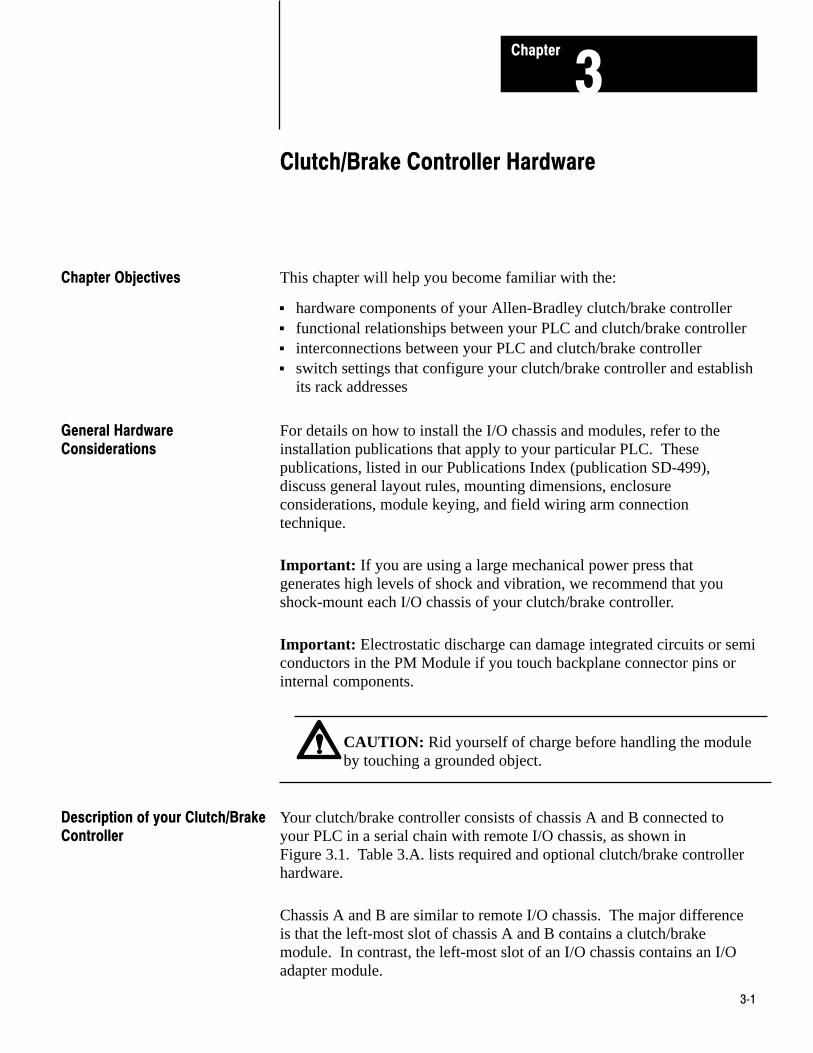
Your clutch/brake controller consists of chassis A and B connected toyour PLC in a serial chain with remote I/O chassis, as shown inFigure 3.1. Table 3.A. lists required and optional clutch/brake controllerhardware.
Chassis A and B are similar to remote I/O chassis. The major differenceis that the left-most slot of chassis A and B contains a clutch/brakemodule. In contrast, the left-most slot of an I/O chassis contains an I/Oadapter module.
Chapter Objectives
General HardwareConsiderations
Description of your Clutch/BrakeController

Clutch/Brake Controller HardwareChapter 3
3�2
Figure 3.1Overview of a Clutch/Brake Controller
Remote I/O
A-B Programmable Controllerwith Remote I/O
Chassis A
Chassis B
Voting Processor AClutch/Brake Module
RemoteI/O
Clutch/BrakeCommunications
12246
Remote I/OAdapter Module
Chassis C
RemoteI/O
Voting Processor BClutch/Brake Module
Remote I/OAdapter Module
Remote I/O ChassisRemote
I/Oother I/O chassisindependent of theClutch/Brake Controller

Clutch/Brake Controller HardwareChapter 3
3�3
Table 3.ARequired and Optional Hardware
Quantity Item Cat. No. Function
Important: (You must use 8�point modules with 2�slot addressing)
Required Hardware
2 Clutch/Brake Module 1771�PM Monitors and controls the press
2 Wiring Arm 1771�WB Connections to 1771�PM
2 I/O Chassis 1771�A2B Contains the modules
10 120V AC Input Modules 1771�IA Monitors press inputs
2 120V AC Isolated Output Modules(Series C) 1771�OD Controls press outputs
Optional Hardware
2 120V AC Output Modules 1771�OA Display of diagnostic messages
1 120AC Output Module 1771�OA Controls optional indicators
2 120V AC Input Modules 1771�IA Dump valve circuit
2 120V AC Isolated Output Modules(Series C) 1771�OD Dump valve and/or micro�inch circuit
2 I/O chassis 1771�A4B Substitute chassis when using theoptional dump valve circuit.
1 120V AC Output Module 1771�OA Micro�inch indicator
2 120V AC Input Modules 1771�IA Micro�inch circuit
2 120V AC Input Modules 1771�IA Additional operator stations
Clutch/brake modules operate in parallel to monitor and control yourpress. Clutch/brake modules are also called “voting processors” becausethey must always have a consensus. Unless both voting processorsconstantly agree that they sense identical conditions in your clutch/brakepress system, either or both voting processors stop press motion orprevent it from starting.
Your clutch/brake controller monitors and controls your press. Althoughyour PLC does not control your press, it does configure and enable theclutch/brake controller. Your PLC ladder program can monitor inputs to,and the status of, your clutch/brake controller. This allows your PLC tocontrol other indicators, machines, or processes related to your presssystem.

Clutch/Brake Controller HardwareChapter 3
3�4
In addition to chassis A and B, you must connect your PLC to at least onelocal or remote I/O chassis, chassis C. You need two, three, or four inputsat a local or remote I/O chassis.
Important : You must use 2-slot addressing and 8-point (single-density)I/O modules.
Typical twinaxial cable connections of your clutch/brake controller areshown in Figure 3.2. Connect your clutch/brake controller to your PLC aspart of its remote I/O distribution network. Use Twinaxial Cable (cat.no.1770-CD) and Terminators (cat. no. 1770-XT).
Connect chassis A next to chassis B in the serial chain as shown inFigure 3.2. You may connect one or more remote I/O chassis in the sameserial chain. Also, you may connect remote I/O chassis to otherdistribution channels at the I/O scanner module of your PLC.
Connect four Terminator Resistors (cat. No. 1770-XT) as shown inFigure 3.2. Connect one at:
the scanner module the last chassis, whether it is a clutch/brake chassis or a remote I/O
chassis each end of the cable that connects chassis A and B at terminals 7, 8
and 9 of the 1771-PM module field wiring arms
For more information on how to connect remote I/O channels, refer to theinstallation publications that apply to your particular PLC. Also refer toProduct Data of the Remote I/O Adapter Module. These publications arelisted in our Publications Index (publication SD499)
Twinaxial Cable Connections

Clutch/Brake Controller HardwareChapter 3
3�5
Figure 3.2Typical Twinaxial Cable Connections
BlueShield
Clear
BlueShield
Clear
BlueShield
Clear
BlueShield
Clear
BlueShield
Clear
BlueShield
Clear
BlueShield
Clear
BlueShield
Clear
Terminator(cat. no.1770 -XT)
Terminator(cat. no.1770-XT)
Terminator(cat. no.1770 -XT)
Terminator(cat. no.1770 -XT)
Terminal Strip on 1772 - SD,SD2 Remote I/O Scanner/Distribution Module (PLC - 2)
Processor/Scanner
RemoteI/O Chassis1771 -ASBAdapterModule
Use Twinaxial Cable(cat. no. 1770 -CD)for all cable connections.
Chassis A
Chassis B
12248
or
Terminal Block on1775 - S4A, - S4B, -S5,
Connector on PLC - 5Processor
Connector on 5/50 - RS2Remote I/O Scanner (PLC -5/250)
or
or
Chassis C
1771 - WBWiring Arm
1771 - PMModule
1771 - WBWiring Arm
1771 - PMModule
I/O Scanner Module (PLC -2)

Clutch/Brake Controller HardwareChapter 3
3�6
Although this manual describes a single clutch/brake controller, you mayconnect your PLC to multiple controllers, each controlling a separatepress. Each clutch/brake controller uses two remote I/O racks for chassisA and B. For example, since a PLC-3 controller can support as many as32 I/O racks, you may connect it to as many as 15 clutch/brake controllerswith two additional I/O racks for modules in chassis C.
You can operate your press using up to four operator stations and anoptional control panel. Installations vary according to the type ofmechanical press and its application requirements. The number ofstations, control switches contained in each, and the control panel couldbe as follows:
Assembly Control Switches Notes
Control Panel and/or Station 1 Mode selectArm continuousStop�on�topL/R InchPress enableReset latched messagesLamp testL/R RunE�Stop
11
1 and/or 3233322
Stations 2 thru 4 L/R RunStop On TopE�Stop
2 2 and/or 3
2
1 Connect these switches to input modules in chassis A and B (Figure 6.10).2 Connect these switches to input modules in chassis A and B (Figures 6.11 thru6.12).3 These switches are inputs for command rungs (Figures 4.6 thru 4.8). Connectthese switches to input modules in remote I/O chassis C (Figure 6.15).
Multiple Clutch/BrakeControllers
Panel Switches and OperatorStations
Clutch/Brake Controller HardwareChapter 3
3�7
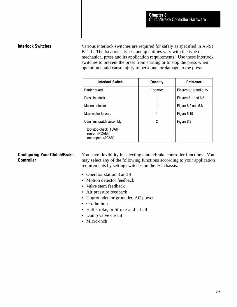
Various interlock switches are required for safety as specified in ANSIB11.1. The locations, types, and quantities vary with the type ofmechanical press and its application requirements. Use these interlockswitches to prevent the press from starting or to stop the press whenoperation could cause injury to personnel or damage to the press.
Interlock Switch Quantity Reference
Barrier guard 1 or more Figures 6.10 and 6.15
Press interlock 1 Figures 6.1 and 6.5
Motion detector 1 Figure 6.2 and 6.6
Main motor forward 1 Figure 6.10
Cam limit switch assembly 2 Figure 6.9
top�stop�check (TCAM)run�on (RCAM)anti�repeat (ACAM)
You have flexibility in selecting clutch/brake controller functions. Youmay select any of the following functions according to your applicationrequirements by setting switches on the I/O chassis.
Operator station 3 and 4 Motion detector feedback Valve stem feedback Air pressure feedback Ungrounded or grounded AC power On-the-hop Half stroke, or Stroke-and-a-half Dump valve circuit Micro-inch
Interlock Switches
Configuring Your Clutch/BrakeController

Clutch/Brake Controller HardwareChapter 3
3�8
Figure 3.3Backplane Switch Settings
BackplaneSwitches
Assembly
ChassisA and B
Position:
ON
OFF
ON
OFF
ON
OFF
ON
OFF
ON
OFF
ON
OFF
ON
OFF
Function:
Use Stations 3 and 4
Stations 3 and 4 not used
Use Motion Detector Feedbck
Motion Detector Feedback not used
Use Valve Stem Feedback
Valve Stem Feedback not used
Use Air Pressure Feedback
Air Pressure Feedback not used
Ungrounded AC Power
Grounded AC Power
Use On-The-Hop
On-The-Hop not used
SwitchNo:
2
3
4
5
6
7
8
1 2 3 4 5 6 7 8ON
OFF
Always OFF
ON
OFF OFF
IMPORTANT: 12249Make backplane switch settings in chassis A and B identical.
Use Stroke�And�A�Half
Use Half�Stoke

Clutch/Brake Controller HardwareChapter 3
3�9
Important: There is no backplane switch setting to configure the optionaldump valve circuit. You configure the optional dump valve circuit byinserting dump valve modules (cat. no. 1771-OD and 1771-IA) intomodule group 4, slots 0 and 1, respectively of chassis A and B. You mustalso set bit 14 unconditionally in your configuration rungs.
Important: To configure your clutch/brake controller for Micro-inch, seechapter 4 “Module Group 5, Slot 0 Reserved for Micro-inch”.
Important : Your PLC ladder program must include unconditionedconfiguration rungs that set or reset configuration bits to match thesettings of backplane switches. Refer to chapter 4.
Establish the address of chassis A and B in each clutch/brake module sothe PLC can communicate with it. Use valid rack addresses asdetermined by your PLC.
Switch assembly SW-1 determines the rack address. It is located under asliding cover plate on the left side of the clutch/brake module near the top.Loosen the two screws holding the cover plate and slide it open. Locateswitch assembly SW-1 at the top of the printed circuit board as shown inFigure 3.4.
Using switch assembly SW-1, designate chassis A and B as follows:
Chassis A - any rack address having position 6 OFFChassis B - next consecutive upper or lower rack address
Important : If your ladder program monitors rack adapter fault bits foreach chassis containing a clutch/brake module, the fault bits will indicatea faulted rack whenever the module trips power to I/O swingarms. This isbecause clutch/brake modules stop all communciation with the PLC untilthey verify that swingarm power has been disconnected.
Important : Always configure I/O racks assigned to clutch/brakecontrollers as full racks, so the PLC can write configuration bits to eachPM chassis in Module Group 7.
Rack Address of Chassis A and B

Clutch/Brake Controller HardwareChapter 3
3�10
Figure 3.4Rack Address Switch Setting on 1771�PM Module
PLC-2/30PLC-5/25
1234567
1
onononononononononononononononononononononononononononononononon
2
ononononononononononononononononoffoffoffoffoffoffoffoffoffoffoffoffoffoffoffoff
Switch Assembly SW-1 Position
N O TE : C hassis A and B m ust have consecutive rack addresses.
1 2 3 4 5 6 7 8ON
OFF
ON
OFF OFF
1 2 3 4ON
OFF
S W -1 S W -2
A lw ays O N (star tingM odu le G roup 0)
A lw ays O FF
A lw ays O N (57.6K baud)
3
ononononononononoffoffoffoffoffoffoffoffononononononononoffoffoffoffoffoffoffoff
12250
PLC-3
0001020304050607101112131415161720212223242526273031323334353637
4
ononononoffoffoffoffononononoffoffoffoffononononoffoffoffoffononononoffoffoffoff
5
ononoffoffononoffoffononoffoffononoffoffononoffoffononoffoffononoffoffononoffoff
6
onoffonoffonoffonoffonoffonoffonoffonoffonoffonoffonoffonoffonoffonoffonoffonoff
Chassis
BABABABABABABABABABABABABABABABA
Rack Addresses
PLC-5/250

Clutch/Brake Controller HardwareChapter 3
3�11
For example, if you choose rack address 2 for chassis A, you must chooserack address 1 or 3 for chassis B.
Set the rack address in each clutch/brake module. Place a label on eachclutch/brake module to identify in which chassis, A or B, it belongs.
Important: Chassis A and B rack addresses must be unique. No I/Ochassis can have the same rack address as either chassis A or B. Thisrestriction prohibits using the rack address of either chassis A or B for anycomplementary I/O chassis (a chassis with the same module addresses buthaving input modules where chassis A and B have output modules, andoutput modules where chassis A and B have input modules). Thisrestriction also prohibits using the rack address of either chassis A or Bfor any partial remote I/O chassis (a chassis that starts with module group2, 4, or 6). (Refer to chapter 4, Module Group 7, PLC Command Rungs,for reasons why you must restrict the use of this address.)
Triacs of your clutch/brake controller turn on in sequential order. Triacsconnected to the high AC power line (L1) turn on before those in thetriac-solenoid string connected to the low AC power line (L2). If theaddresses are reversed, the triacs will turn on out of sequence, and theclutch/brake controller will not operate.
Set switch 1 on switch assembly SW-2 to the ON position. This sets themodule’s communication rate at 57.6K baud. Be sure that you set thecommunication rate of both 1771-PM modules and the processor’sscanner to 57.6K baud, as well.
The worst case time required for the clutch/brake controller to respond toa change of input depends on Module-response and triac-switching times:
CharacteristicDelay(ms)
1771�IA module response time 26
1771�PM module response time 10
Triac switching time 8
Total response time 44
Setting the Communication Rate
Response Time

Clutch/Brake Controller HardwareChapter 3
3�12
The number of degrees that the shaft continues to rotate, beyond themoment in time when the input changes, depends on the speed of rotation.The greater the number of strokes per minute (SPM), the further the shaftrotates before a command from the clutch/brake controller is applied. Theresponse time of 44ms is represented in degrees of shaft rotation thatincreases as the rate of press operation increases (Figure 3.5).
Figure 3.5Response Time of Clutch Brake Controller
100
90
80
70
60
50
40
30
20
10
0
0 5 10 15 20 25
SPM
Degrees of Shaft Rotation12251
Important: When estimating the braking distance in degrees of rotation,add the response time of the controller (Figure 3.5) to the specifieddownstroke or upstroke braking distance of your press.
Locations of all clutch/brake controller modules are shown in Figure 3.6.Note that some of these modules are optional.
CAUTION: Do not place any I/O module in module groups6 or 7 of chassis A or B. These module group locations arenon-functional and reserved for future use. If you use a slotpower supply, install it in module group 7.
Important : Use series C or later 1771-OD modules because they haveimproved electrical noise immunity. Refer to Electrical NoiseSuppression, in chapter 6, for a method of suppressing surge transientnoise.
Module Placement

Clutch/Brake Controller HardwareChapter 3
3�13
Figure 3.6Module Locations
Required 1771 -IA modules forpress inputs chassis A & Bmodule group 0, slots 0 & 1module group 1, slot 1module group 2, slots 0 & 1
Optional 1771 -OA modules for display ofmessage codes, brake fault, run window and micro inch.module group 3, slot 1 chassis Amodule group 5, slot 1, chassis A & BOptional 1771 -IA modules for micro-inch inputs, chassis A & Bmdoule group 5, slot 0
1771 -PMmodule
Optional 1771 -IA modules for station 3 & 4inputs chassis A & B (remove them if you donot configure for stations 3 & 4module group 1, slot 0
These slots must remain empty in chassis A & Bmodule group 6, slots 0 & 1module group 7, slots 0 & 1
Required 1771 -OD modules for outputsto solenoid valves, Chassis A & Bmodule group 3, slot 0Optional micro -inch indicator, chassis B1771 -OA, module group 3, slot 1
Optional modules for dumpvalve in chassis A & B1771 -OD, module group 4, slot 01771 -IA, module group 4, slot 1
Chassis A1771 -A4, -A4B
1771 -PMmodule
Chassis A1771 -A4, -A4B
12247
0 1 2 3 4 5 6 7
0 1 2 3 4 5 6 7
Important: Use 1771�A2, �A2B chassis when not using optional dump valves, display of diagnostic message codes, nor micro�inch inputs.

Clutch/Brake Controller HardwareChapter 3
3�14
Install the keying bands on the I/O chassis backplane connector as shownin Figure 3.7. After you install keying bands in chassis A and B, you caninsert only a clutch/brake module in the left-most slot of chassis A and B.
Figure 3.7Keying
2468101214161820222426283032343638404244464850525456
2468101214161820222426283032343638404244464850525456
Insert keying bands so that youcan install only a 1771-PMmodule in this slot.
12252
Chassis A and B
Keying

Chapter
4
4�1
PLC Ladder Programming
This chapter will help you become familiar with:
programming fundamentals as they relate to your clutch/brakecontroller
the need for press configuration rungs relationships between your press configuration rungs and backplane
switch settings relationships between configuration rungs and voting processor
firmware the option of monitoring the press through your PLC ladder program the option of using PLC report generation to display messages that you
have stored.
Your PLC ladder program is composed of instructions that you enter intoPLC memory. These instructions are organized into rungs. Theytypically monitor inputs and control outputs.
Your PLC ladder program does not control your clutch/brake controller,but it does configure and enable it. Although your ladder program cannotcontrol any clutch/brake controller outputs, it controls output image tablebits to configure and enable the voting processors. Your ladder programmay examine input image table bits to monitor clutch/brake controllerfunctions as we will explain later.
This chapter concentrates on PLC ladder programming that relates to yourclutch/brake controller. For more details on ladder programming, refer tothe programming manual that applies to your PLC processor. Thesepublications are listed in our Systems Division Publication Index(publication SD499).
PLC ladder programming is described in this chapter as it relates toclutch/brake controller hardware and voting processor firmware(Figure 4.1).
Chapter Objectives
Programming Fundamentals

PC Ladder ProgrammingChapter 4
4�2
Figure 4.1Overview of Clutch/Brake Controller
1771 - PMVoting
Processor
ChassisA
1771 - PMVoting
Processor
ChassisB
1771 - ASBRemote I/O
Adapter
ChassisC
The firmware in votingprocessors A and Bmonitors and controls the press.
ConfigurationSwitchInputs
Other inputsthat areindependentof theClutch/brakecontroller
C/BPress
A-B Programmable Controllerwith Remote I/O
Your ladder diagramprogram configures andenables voting processorsA and B, while it monitorsand controls I/O throughremote I/O adapters.
PLCLadderProgram
I/O Control Rungs
Configuration Rungs
I/O Control Rungs
12253
(optional)

PC Ladder ProgrammingChapter 4
4�3
You have flexibility in selecting clutch/brake controller functions bysetting/resetting configuration bits. Use any of the following functionsaccording to your application requirements:
Functions Bit
Stations 3 and 4 01
Motion detector feedback 02
Valve stem feedback 03
Air pressure feedback 04
Ungrounded or grounded AC power 05
On�the�hop 06
Half�stroke or Stroke�and�a�half 07
Dump valve circuit 14
You enable various functions by programming configuration rungs to set(turn on) or reset (turn off) configuration bits 01 thru 07 and 14 in theoutput image table word for module group 7, chassis A and chassis B.Bit addresses are shown in Figure 4.2. Example configuration rungs areshown in Figure 4.3 through Figure 4.5. Program your configurationrungs according to the requirements of your press system.
Be sure to set or reset each configuration bit 01 thru 07 and 14 withunconditioned rungs. They contain only output instructions, such as latch,unlatch, or output energize. Bits set by these rungs do not change duringpress operation. The latching or unlatching of these bits must correspondwith backplane switch settings covered in chapter 3.
Figure 4.2Bit addresses of Output Image Table Word for Module Group 7 of Chassis A & B
PLC-2/20 PLC-3PLC-2/30 PLC-5/250 PLC-5
0y7/xx Oyy7/xx O:y7/xx
where yy = rack address per Figure 3.4 xx = bit number 00 - 17
Important: Do not use bits 00 and 15-17 for any purpose.
Configuration Rungs

PC Ladder ProgrammingChapter 4
4�4
Figure 4.3Example PLC Configuration Rungs for Bits 01 thru 07 and 14 (PLC�2 Family)
U057
01
U067
01
Stations 3 and 4 not used
L057
02
L067
02
Motion detector feedback used
L057
03
L067
03
Valve stem switch feedback used
U057
04
U067
04
Air pressure switch feedback not used
L057
05
L067
05
Ungrounded AC power
U057
06
U067
06
On-the-hop not used
U057
07
U067
07
Stroke�and�a�half used
L057
14
L067
14
Optional dump valve triacs used

PC Ladder ProgrammingChapter 4
4�5
Figure 4.4Example PLC Configuration Rungs for Bits 01 thru 07 and 14 (PLC�3 and PLC�5/250)
UO0057
01
Stations 3 and 4 not usedUO0067
01(
LO0057
02
LValve stem switch feedback used
U04
Air pressure switch feedback not used
L05
Ungrounded AC power
UOn-the-hop not used
U07
L14
Optional dump valve triacs used
)
)
)
)
)
)
)
O0067
02(
O0067
03(
UO0067
04(
O0067
05(
UO0067
06(
UO0067
07(
O0067
14(
O0057
O0057
O0057
O0057
O0057
O0057
NOTE: Unconditionally latch or unlatch bits 0 through 7 and 14 for chassis A and B as shown to use these functions.
L
L
L
L
06
Use this address format for PLC-5/250 processors
U01
)O:067
01(
O:057
U
Motion detector feedback used
03
Half-stroke or Stroke-and-a-half used

PC Ladder ProgrammingChapter 4
4�6
Figure 4.5Example PLC Configuration Rungs for Bits 01thru 07 and 14(PLC�5 family)
UO:67
01
Stations 3 and 4 not usedUO:57
01(
L02
Motion detector feedback used
Valve stem switch feedback used
Ungrounded AC power
On-the-hop not used
Optional dump valve triacs used
)
02(
NOTE: Unconditionally latch or unlatch bits 0 through 7 and 14 for chassis A and B as shown to use these functions.
L
O:67
O:57
L03
)
03( L
O:67
O:57
Air pressure switch feedback not used
UO:67
04
UO:57
04(
L05
)
05( L
O:67
O:57
UO:67
06
UO:57
06(
Stroke-and-a-half or Half-stroke used
UO:67
07
UO:57
07(
LO:67
14
LO:57
14(

PC Ladder ProgrammingChapter 4
4�7
As listed in Table 4.A, backplane switch positions 2 thru 8 correspondwith configuration bits 01 thru 07. The voting processors in yourclutch/brake modules allow press operation only if the set (on) and reset(off) states of configuration bits in your program correctly match the ONand OFF settings of corresponding backplane switches. The votingprocessors check for correct configuration when you apply power to yourclutch/brake controller or change its mode of operation using the modeselect switch.
Table 4.ACorresponding Backplane Switch Settings and Configuration Bits
BackplaneSwitch
Settings(figure 3.3)
ConfigurationBits
Backplane switch settings and configuration bitsmust be identical
Pos. Setting Bit: Status: Function:
2 ON 01 Set Use Stations 3 and 4
OFF reset Stations 3 and 4 not used
3 ON 02 set Use Motion Detector Feedback
OFF reset Motion Detector Feedback not used
4 ON 03 set Use Valve Stem Feedback
OFF reset Valve Stem Feedback not used
5 ON 04 set Use Air Pressure Feedback
OFF reset Air Pressure Feedback not used
6 ON 05 set Ungrounded AC Power
OFF reset Grounded AC Power
7 ON 06 set Use On�The�Hop
OFF reset On�The�Hop not used
8 ON 07 set Use Half�stroke
OFF reset Use Stroke�And�A�Half
Module Group 4 Slot 1, Chassis A&B1771�IA
Set Use Dump Valve Outputs
Module Group 4Slot 1, Chassis A&Bis EMPTY
14reset Dump Valve Outputs not used
Matching Configuration Bits andBackplane Switches

PC Ladder ProgrammingChapter 4
4�8
Your ladder diagram program can send four commands to the clutch/brakecontroller by setting command bits 10-13 in the output image word formodule group (MG) 7, Slot 1 for I/O chassis A and B:
Command Bit
Press enableStop�on�topReset latched messagesLamp test
10111213
These commands can be issued manually by an operator pushing a switch,or automatically by a switch closure in your machinery. They function asfollows:
Output Status Condition Controlled by PM Module
Press EnableBit 10
must be ON
OFF
To enable motion in any mode
Immediately turns OFF triac outputs
Stop�on�top(Continuous mode, only)
Bit 11
off�to�ontransition
must be OFF
Turns OFF solenoid outputs the next time therun�on cam switches open
To start or maintain continuous stroking
Reset Latched MessageBit 12
off�to�ontransition 1
Clears any latched or tripped message codeshown in MG 5, Slot 1, as long as the conditionthat caused the message no longer exists.
Lamp TestBit 13
ON
OFF
Turns ON all these outputsBrake Fault , Run Window, Micro�inch Message,and other diagnostic message lamps
Turns OFF these outputs
1 Holding this bit ON may inhibit the capture of subsequent L or t messages.
Bit addresses for these command bits are shown in Figure 4.2. ExamplePLC command rungs are shown in Figure 4.6 through Figure 4.8.
To enable these commands, write ladder program rungs that areconditioned with examine-on/examine-off instructions to monitorcorresponding switch inputs wired to I/O chassis C. You can use anyavailable discrete module terminals (excluding those in chassis A or B)for these inputs (Figure 6.15). For additional information refer to chapter6, Inputs to Chassis C .
PLC Command Rungs

PC Ladder ProgrammingChapter 4
4�9
Figure 4.6Example PLC Command Rungs for Bits 10 thru 13 (PLC�2 Family)
132
13
057
10
PRESS ENABLE Switch
Optional conditions
13
067
10
Enable Press Operation
132
15
057
11
132
15
067
11
132
14
057
12
132
14
067
12
132
16
057
13
132
16
NOTE:
067
13
STOP-ON-TOP Switch
RESET Switch
Reset latched messages
LAMP TEST Switch
Test optional indicators
Command Stop-on-top
132
PLC command bits 10 through 13 use conditioned logic. Do not latch or unlatch instructions. Correspondingswitch input wiring is shown in Figure 6.15.

PC Ladder ProgrammingChapter 4
4�10
Figure 4.7Example PLC Command Rungs for Bits 10 thru 13 (PLC�3 and PLC�5/250)
I0032
13
O0067
10
Optional conditions
Enable Press Operation
I0032
15 11
I0032
14 12
I0032
16 13
STOP-ON-TOP Switch
RESET Switch
Reset latched messages
LAMP TEST Switch
Test optional indicators
Command Stop-on-top
O0057
10
11
12
13
O0067O0057
O0067O0057
O0067O0057
Use this address format for PLC-5/250 processors
U01
)O:067
01(
O:057U
NOTE: PLC command bits 10 through 13 use conditioned logic. Do not latch or unlatch instructions. Correspondingswitch input wiring is shown in Figure 6.15.
PRESS ENABLE Switch

PC Ladder ProgrammingChapter 4
4�11
Figure 4.8Example PLC Command Rungs for Bits 10 thru 13 (PLC�5)
I032
13
O:57
10
Optional conditions
Enable Press Operation
15
14
16
STOP-ON-TOP Switch
RESET Switch
Reset latched messages
LAMP TEST Switch
Test optional indicators
Command Stop-on-top
O:67
10
O:57
11
O:67
11
O:57
12
O:67
12
O:57
13
O:67
13
I032
I032
I032
NOTE: PLC command bits 10 through 13 use conditioned logic. Do not latch or unlatch instructions. Correspondingswitch input wiring is shown in Figure 6.15.
PRESS ENABLE Switch

PC Ladder ProgrammingChapter 4
4�12
We summarize the bits in module group 7 used for determiningconfiguration requirements and enabling operator commands (Figure 4.9).
Figure 4.9Functions of PLC Configuration and Command Bits
17 16 15 14 13 12 11 10 07 06 05 04 03 02 01 00
PLC Command Bits
Output image table word,
Module Group 7, ChassisA & B
PLC Configuration Bits
Bit Bit Status Type of
No: Function: Set Reset Rung:
01 Stations 3 and 4 Used Not Used Unconditioned
02 Motion Detector Feedback Used Not Used Unconditioned
03 Valve Stem Feedback Used Not Used Unconditioned
04 Air Pressure Feedback Used Not Used Unconditioned
05 AC Power Configuration Ungrounded Grounded Unconditioned
06 On�The�Hop Used Not Used Unconditioned
07 Stroke�and�a�half or Half�stroke Not Used Used Unconditioned
10 Press Enable (PLC Command) Enabled Disabled Conditioned
11 Stop�On�Top (PLC Command) Enabled Disabled Conditioned
12 Latched Messages (PLC Command) Enabled Disabled Conditioned
13 Lamp Test (PLC Command) Enabled Disabled Conditioned
14 Dump Valve Triacs Used Not used Unconditioned
NOTES: Do not use bits 00 and 15 � 17 for any purpose. See Figure 4.2 for bit addresses See Figure 4.3 through 4.8 for programming
12254
Summary of PLC Configurationand Command Rungs

PC Ladder ProgrammingChapter 4
4�13
Important: Use module group 5, slot 0 only if your mechanical powerpress is equipped for micro-inch.
When you insert an input module (1771-IA) into this slot of chassis A andB, the processor recognizes micro-inch inputs at terminals 0, 1, 2. For thewiring of these terminals refer to chapter 6, Figure 6.4 orFigure 6.8.
Module group 6 is non-functional and reserved for future use.
Your program must use the output image table word associated withmodule group 7 as a storage word for configuring your clutch/brakemodules (Figure 4.9). The processor transmits configuration data to theclutch/brake modules in each I/O scan.
CAUTION: Do not assign any I/O module to module group 7of the rack address assigned to chassis A and B. Unexpectedpress operation will occur with possible damage to equipmentand/or injury to personnel. However, you may install a slotpower supply in module group 7, if needed.
Important : Be sure to assign full rack addresses for chassis A and B,regardless of whether you are using the optional dump valve and/ormicro-inch circuit. This guards against assigning an I/O module tomodule group 7.
Refer to Rack Address of Chassis A and B, in chapter 3, for instructionson assigning rack addresses.
Your PLC ladder program cannot control outputs of your clutch/brakecontroller. However, your PLC ladder program can monitor anyclutch/brake controller input or output because the I/O image table ofchassis A and B is in the PLC data table.
Input image table bit addresses for chassis A and B are listed in tables Athru F in appendix 1. You may monitor these addresses. However, do notexamine them as conditions for configuration rungs shown in Figures 4.3through Figure 4.5. If you do, PM modules may stop the press. Thenyou must cycle power to restart.
Module Group 5, Slot 0Reserved for Micro�Inch
Module Groups 6 and 7Reserved for Data Storage
Monitoring Clutch/BrakeController Inputs and Outputs

PC Ladder ProgrammingChapter 4
4�14
For an example of monitoring a clutch/brake controller function, assumethat you wish to turn on a indicator while your clutch/brake controller isin continuous mode. You would wire your CONTINUOUS indicator to aterminal of an output module in any I/O chassis. You would also programa rung with one examine-on instruction and one output-energizeinstruction:
the examine-on instruction monitors input image bit 03 for modulegroup 0 chassis A or B.
the output energize instruction controls the CONTINUOUS indicator.
Important: Do not store data in unused data table addresses for chassis Aand B. These are reserved for future enhancements for the clutch/brakecontroller.
Your PLC ladder program can monitor clutch/brake controller functionsfor report generation. This allows you to display, through an RS-232-Cperipheral device, any of the following:
operator instructions fault correction procedures status reports diagnostic message codes
The clutch/brake module generates diagnostic message codes presented intable 7.C. Use them to generate messages that you have stored in PLCmemory. These messages can be troubleshooting instructions to yourpress operators. For detailed descriptions of report generation, see thefollowing publications:
For PLC-2 family processors:
PLC-2 Family Report Generation Module (cat. no. 1770-RG) User’sManual (publication 170-815)
For PLC-3 processors:
I/O Scanner-Message Handling Module (cat. no. 1775-S4B) User’sManual (publication 1775-6.5.3)
Peripheral Communications Module (cat. no. 1775-GA) User’s Manual(publication 1775-6.5.4)
For PLC-5 family processors:
BASIC Module (cat. no. 1771-DB) User’s Manual (publication1771-6.5.34)
Report Generation

PC Ladder ProgrammingChapter 4
4�15
You should now be familiar with required and optional PLC ladderprogramming needed to configure and monitor your clutch/brakecontroller. Complete your ladder diagram programming addresses afteryou have wired your press system as described in chapter 6. Clutch/brakecontroller functions (Table 4.B) are summarized on the next page.
Table 4.BSummary of Clutch/Brake Controller Functions
Function or Command Operating Mode Description
� Off Clutch/brake controller locks out press motion
� Inch The operator can jog the press through a complete cycle bypressing and releasing the pair of INCH buttons. If INCHbuttons are held, the press will stop at the top of its stroke.
� Micro�inch This mode of operation lets you run your press at low speeds (1 to 5spm) for setting up dies and making trial runs. You mustsupply a separate drive and clutch/brake assembly to drive theshaft with full tonnage capacity at low press speeds, by�passingthe flywheel.
� Single�stroke[ 1 ]
The press completes one cycle and then stops on top, providedthe operator holds both RUN buttons until completion of thedown stroke.
� Continuous[ 1 ]
Operators must assert the ARM CONTINUOUS switch and allstation RUN buttons within five seconds, and then hold the RUNbuttons for half a stroke (or 1 1/2 strokes) if so configured tostart the press in continuous mode. Thereafter, the press runsuntil stopped by a stop�on�top command, or when a fault isdetected.
Stop�on�top(cycle stop)
Continuous This command, from a switch wired to the clutch/brakecontroller or from the PLC, stops the press at a predeterminedpoint.
On�the�hop Single�stroke Releasing and pressing both RUN buttons during a specificportion of the upstroke causes the press to continue runningonto the next stroke without stopping. This is a configurableoption.
Half�stroke orStroke�and�a�half
Continuous The operator must press both RUN buttons for 1/2 or 1 1/2press cycles before the press can run on its own. This is aconfigurable option. Run buttons must be held until Run�on(take�over) Cams are made.
[ 1 ] Cam limit switches must indicate that the press is in the near�top position before motion can start insingle or continuous mode.
Summary of Clutch/BrakeController Functions
PC Ladder ProgrammingChapter 4
4�16
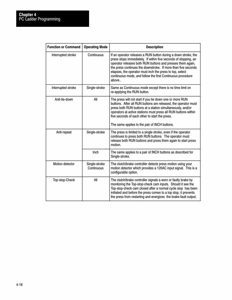
Function or Command DescriptionOperating Mode
Interrupted stroke Continuous If an operator releases a RUN button during a down stroke, thepress stops immediately. If within five seconds of stopping, anoperator releases both RUN buttons and presses them again,the press continues the downstroke. If more than five secondselapses, the operator must inch the press to top, selectcontinuous mode, and follow the first Continuous procedureabove..
Interrupted stroke Single�stroke Same as Continuous mode except there is no time limit onre�applying the RUN button.
Anti�tie�down All The press will not start if you tie down one or more RUNbuttons. After all RUN buttons are released, the operator mustpress both RUN buttons at a station simultaneously, and/oroperators at active stations must press all RUN buttons withinfive seconds of each other to start the press.
The same applies to the pair of INCH buttons.
Anti�repeat Single�stroke The press is limited to a single stroke, even if the operatorcontinues to press both RUN buttons. The operator mustrelease both RUN buttons and press them again to start pressmotion.
Inch The same applies to a pair of INCH buttons as described forSingle�stroke.
Motion detector Single�strokeContinuous
The clutch/brake controller detects press motion using yourmotion detector which provides a 120AC input signal. This is aconfigurable option.
Top�stop�Check All The clutch/brake controller signals a worn or faulty brake bymonitoring the Top�stop�check cam inputs. Should it see theTop�stop�check cam closed after a normal cycle stop has beeninitiated and before the press comes to a top stop, it preventsthe press from restarting and energizes the brake�fault output.

Chapter
5
5�1
Voting Processor Firmware
This chapter will help you become familiar with:
operation of your voting processor firmware operational sequences for controlling your press
A clutch/brake controller has two clutch/brake modules, one in chassis Aand the other in chassis B. Each clutch/brake module contains firmwarethat makes it function as a voting processor. Both voting processorscontain identical firmware programs that independently monitor yourclutch/brake controller I/O while controlling the press.
While running their firmware programs, both voting processors constantly“vote” on the status of your press. Both voting processors must alwayshave a consensus. If they find that they don’t agree on their perceivedconditions of your press, they either stop the press or prevent it fromstarting.
Also, both voting processors constantly check their communicationchannels. Press motion is stopped or inhibited if either voting processordetects a loss of communications with the PLC or the other votingprocessor. A failure in one voting processor is immediately seen as acommunication loss by the other voting processor.
Finally, voting processors control the operational sequences that youroperators must perform in inch, single, and continuous modes.
Each voting processor (PM module) controls one seal relay and onecrowbar relay. All E-STOP switches are connected in series with sealrelay contacts. If any of these contacts opens or if the PM module detectsa trip condition, solenoid power is disconnected. If a PM module detectsthat solenoid power should be off when on, it turns on the crowbar relayto blow the solenoid power line fuses. At clutch/brake start, both PMmodules test their crowbar relays without blowing the line fuses. Wiringdiagrams in chapter 6 show these connections.
Chapter Objectives
Operation of Voting Processors
Emergency Shut Down

Voting Processor FirmwareChapter 5
5�2
PM modules continuously monitor your clutch/brake system for a trip orstop condition. Either condition halts and/or prevents press operation.
For this condition PM modules remove solenoid power by
Trip Removing power from field wiring arms
Stop Turning off outputs from the output modulecontrolling the solenoids
Trip condition - A PM module turns off swing arm output power byde-energizing its seal relay output when it detects these trip conditions:
lost communications with the other PM module for 100ms a change in wiring of operator stations 1 thru 4 a short or open solenoid triac short or open solenoid feedback [1] connections are wired but not configured feedback connections are configured but not wired feedback signals are not working correctly
[1] feedback from valve stem switches, air pressure sensors, and motion detector contacts
Whenever a PM module detects a trip condition, it:
trips power to the wiring arms of the I/O chassis sets rack fault bits stops communication with the PLC
If programmed to monitor rack fault bits, the PLC sees the clutch/brakeI/O chassis as faulted until both PM modules verify that power to wiringarms has been removed. Then they resume communicationsautomatically.
Stop condition - A PM module stops the press or prevents it from startingby turning off output triacs to solenoid valves when it detects stopconditions such as:
lost communications with the other PM module for 50ms lost communications with the PLC for one second cam limit switch signals out of sequence barrier guard opened during continuous mode
This is described further in Chapter 7, Diagnostic Message Codes.
Fault Monitoring

Voting Processor FirmwareChapter 5
5�3
The PM Module uses cam limit switches to determine press slide position.(Figure 5.1 and Table 5.A). You set two independent cam limit switchassemblies to the same settings so that:
run-on contacts are closed in the near bottom and upstroke zones top-stop-check contacts are closed in the downstroke and near-bottom
zones anti-repeat contacts open during mid-upstroke for at least 70ms. Set the
open span to the approximate number of rotational degrees (100 - 450)according to the speed of the press (1spm - 100spm).
Up�Stroke Span vs. Press Speed for Anti�Repeat Contacts
100
90
80
70
60
50
40
30
20
10
PressSpeed
SPM
15 30 45
Open Span During Up - Stroke12971
0 0 0
The anti-repeat cam is not required while operating in inch or micro-inchmode. However, before entering any operating mode, the PM modulechecks that at least one cam limit switch is closed at any point in thecycle.
Operation of Cam Limit Switches

Voting Processor FirmwareChapter 5
5�4
Figure 5.1Cam Limit Switch Settings
Near TopPositionRun - On
Near BottomZone
Upstroke
Anti - Repeatbefore run-on contacts make, or the controller faults.
Run-on contacts must make (not necessarily at the same time)before
Anti-repeat contacts must break for at least 70ms duringupstroke, then make before run-on contacts break, or the controller faults.
Anti-repeat contacts must make (not necessarily at the same time)before run-on contacts break, or the controller faults.
Run-on contracts must break (not necessarily at the same time)
MAKE
MAKE
MAKE
BREAK
MAKE
MAKE
BREAK
MAKE
MAKE
MAKE
MAKE
BREAK
MAKE
MAKE
BREAK
BREAK
BREAK
BREAK
Down-stroke
NearBottom
Up-stroke
NearTop
Run-On Anti-RepeatZone
Comments
Cam Linit Switch Settings
Refer to Diagnostic Messages, table 7.C. Hex codes 80 thru AA, for descriptions of faults causedby cam limit switches.
12970
70 ms
NOTE:Install two mechanically independent cam limit switch assemblies each with three cams and threelimit switches. Set the assemblies to similar settings according to the requirements of your press.
You can set cam limit switches to other configurations provided they meet the make/break conditionslisted below:
Downstroke
Top-Stop-Check
Top�stop�check contacts must make (not necessarily at the same time)
Top�stop�check contacts break, or the controller faults.
Top�stop�check contacts must break (not necessarily at the same time)before anti�repeat contacts break or the controller faults.
before Top�stop�check contacts make or the controller faults.
Top-stop-check
Table 5.AOperation of Cam Limit Switches
ThisCam
In thisMode
With theseConditions Provides the PM Module a Signal:
Anti�Repeat
On�the�hop singlestroke
Run buttons releasedpast bottom
To allow a second stroke when run buttonsare pressed a second time
Run�on Inch and Micro�inch(forward) and Singlestroke
Cam opens at near�topposition To turn OFF triac output for
stop�on�top (cycle stop)
Continuous Cam opens at near�topposition afterstop�on�top command
Single stroke andContinuous
Cam closes atnear�bottom position
To let operator release any depressed runbuttons without interrupting a single strokeor continuous stroking
Top�StopCheck
any Cam closes duringstop�on�top
To energize a Brake Fault output to warnthat the brake is faulty (HazardousCondition)
Inch andMicro�inch(reverse)
Cam opens in near�topposition
To turn OFF solenoid outputs to stop thecycle

Voting Processor FirmwareChapter 5
5�5
Inch and Micro�inch ModesUse inch or micro-inch mode before entering single or continuous modeto position the shaft near the top, or for machine tool set-up. You may jogthe shaft either forward or in reverse. The shaft stops when it moves intothe near top position or when you release an INCH button.
Figure 5.2Operational Sequence for Inch or Micro�Inch Mode
Select inch or micro�inch mode
Has an operator releasedboth INCH buttons?
Has an operator pressedboth INCH buttonssimultaneously?
Both voting processorsenergize their solenoid triacs
to actuate the clutch
Has the shaft moved into itsnear�top position?
Has an operator releasedeither INCH button?
Both voting processorsde�energize their solenoid
triacs to stop the shaft in itsnear�top position
WARNING: If the shaftcoasted past its near�top
position while braking, thebrake is faulty and
hazardous. Repair itimmediately.
WARNING: To guard against thepossibility of personal injury, install akeylock mode select switch so that onlysupervisory personnel can select inchmode.
NOTE: Use inch or micro�inch mode to position the shaft near the top. Operators mayjog the shaft in either direction. The shaft stops when it moves near top position orwhen an operator released an INCH button.
12261
No
No
Yes
Yes
No
Yes
Yes
No
Clutch/Brake Operating Modes
Voting Processor FirmwareChapter 5
5�6
Single Stroke Mode
Use single-stroke mode to actuate the press through a single cycle.
During the downstroke (Figure 5.3)
releasing a RUN button stops the press if the shaft did not enter the near bottom zone, you may resume the
downstroke if the shaft entered the near bottom zone, you must inch the press back
to the near top position before restarting
During the upstroke (Figure 5.4)
the shaft continues automatically through the upstroke
If you enabled on-the-hop , you can start another cycle without stoppingthe press if you
release all RUN buttons after the near bottom position press all RUN buttons after the anti-repeat contacts open during the
upstroke

Voting Processor FirmwareChapter 5
5�7
Figure 5.3Operational Sequence for Downstroke in Single Mode
Select single mode
Is the shaft near the top?
Have all operators released allRUN buttons?
Has each operator pressed hisRUN buttons simultaneously,and within 5 seconds for all
stations?
Both voting processorsenergize their solenoid triacs to
actuate the clutch for thedownstroke Has an operator released a
RUN button?
Select inch mode and position theshaft near the top.
NOTE: Releasing a RUN button during the downstroke stops the press. If the shaft doesnot reach the near�bottom zone, operators may resume the downstroke. If the shaftreaches the near�bottom zone, an operator must inch the press back to the near�topposition. 12262
No
Yes
Yes
NoIs the shaft past the nearbottom zone?
Start upstroke.Go to figure 5.4
Both voting processorsde�energize their solenoid
triacs to stop the shaft. A stopcondition message is
displayed.
Yes
Did the shaft coast into thenear bottom zone while
breaking?
Have all operators released allRUN buttons?
Has each operator pressed hisRUN buttons simultaneously,and within 5 seconds for all
stations?
CAUTION: Releasing a RUNbutton late in the downstroke
can damage the press
No
No
Yes
No
Yes
No
Yes
Yes
Start on�the�hopdownstroke.
From figure 5.4
No
Yes
Main Motor Forward
Yes
No
Voting Processor FirmwareChapter 5
5�8
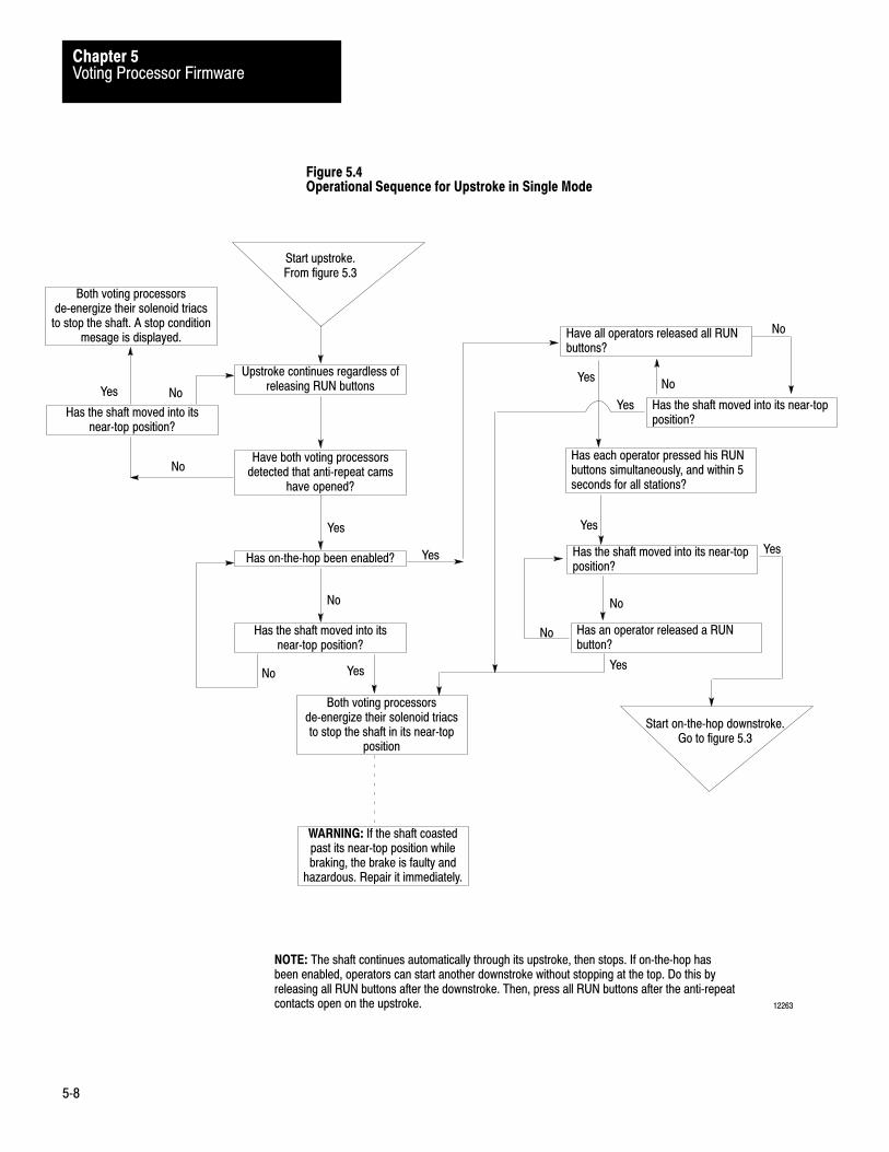
Figure 5.4Operational Sequence for Upstroke in Single Mode
Start upstroke.From figure 5.3
Upstroke continues regardless ofreleasing RUN buttons
Have both voting processorsdetected that anti�repeat cams
have opened?
Has on�the�hop been enabled?
Has the shaft moved into itsnear�top position?
Have all operators released all RUNbuttons?
NOTE: The shaft continues automatically through its upstroke, then stops. If on�the�hop hasbeen enabled, operators can start another downstroke without stopping at the top. Do this byreleasing all RUN buttons after the downstroke. Then, press all RUN buttons after the anti�repeatcontacts open on the upstroke. 12263
Yes
No
Yes
Both voting processorsde�energize their solenoid triacs
to stop the shaft. A stop conditionmesage is displayed.
Has the shaft moved into itsnear�top position?
No
Has each operator pressed his RUNbuttons simultaneously, and within 5seconds for all stations?
Has the shaft moved into its near�topposition?
Has an operator released a RUNbutton?
No
Yes
No
Yes
Yes
Yes
No
Yes
Both voting processorsde�energize their solenoid triacsto stop the shaft in its near�top
position
WARNING: If the shaft coastedpast its near�top position whilebraking, the brake is faulty and
hazardous. Repair it immediately.
Start on�the�hop downstroke.Go to figure 5.3
Has the shaft moved into its near�topposition?
No
No
Yes
Yes
No

Voting Processor FirmwareChapter 5
5�9
Continuous Mode
Select continuous mode when you want to run your press continuously.Do this as follows:
inch the press to the near top position close the barrier guard(s) select continuous mode, and press the ARM CONTINUOUS button (Figure 5.5)
During the first downstroke (Figure 5.6).
releasing a RUN button or opening a barrier guard stops the press if the shaft did not enter the near bottom zone, you may resume the
downstroke within five seconds after a stop if the shaft entered the near bottom zone and is stopped, you must inch
the press to the near top position and press the ARM CONTINUOUSbutton in order to restart press operation.
During the first upstroke (without stroke-and-a-half) (Figure 5.7)
releasing a RUN button does not stop the press opening a barrier guard stops the press if the shaft did not stop in the near top position, inch it there and repeat
the procedure from the beginning
If you configured for half-stroke or stroke-and-a-half requirement
continue holding the RUN buttons until the shaft runs through the first(or second) downstroke and first (or second) near bottom position
releasing a RUN button stops the press, and first downstroke conditionsapply
Once in continuous operation (NO TAG), the press stops whenever
you press stop-on-top the PLC transfers a stop-on-top command a barrier guard opens either voting processor detects a trip or stop condition

Voting Processor FirmwareChapter 5
5�10
Figure 5.5Operational Sequence for Starting Continuous Mode
Select continuous mode
Is the barrier guard closed?
Is the shaft in the near�topposition?
Have all operators released allSTOP�ON�TOP buttons?
Have all operators released allRUN buttons?
NOTE: The arming sequence guards against accidently starting operation in continuous mode.
12264
Yes
Yes
Select inch mode and position theshaft to the near�top position
No
Yes
Has an operator pressed the ARMCONTINUOUS button?
Have 5 seconds elapsed sincepushing ARM CONTINUOUS?
Has each operator pressed hisRUN buttons simultaneously, andwithin 5 seconds for all stations?
Go to First DownstrokeFigure 5.6
No
Yes
No
No
Yes
Yes
No
Yes
No
No
Arming Sequence
Main Motor ForwardNo
Yes

Voting Processor FirmwareChapter 5
5�11
Figure 5.6Operational Sequence for First Downstroke in Continuous Mode
First Downstroke.From figure 5.5
Has an operator released aRUN button, or has a barrier
guard opened?
Both voting processorsde�energize their solenoid triacs
to stop the shaft. A stopcondition mesage is displayed.
Did the shaft coast into thenear�bottom zone while
braking?
CAUTION: Releasing a RUN buttonlate in the downstroke can damagethe press.
NOTE: Releasing a RUN button during the first downstroke stops the press. If the shaft hasnot entered the near bottom zone, operators can resume the downstroke within 5 seconds ofreleasing a RUN button. After 5 seconds, operators must restart continuous mode by meansof the arming sequence. 12265
Yes
Both voting processorsenergized their solenoid triacs
for the first downstroke
Has the shaft reached thenear�bottom position?
Go to First Upstroke.Figure 5.7
Yes
No
No
No
Have 5 seconds elapsed sincethe solenoid triacs were
de�energized?
Have all operators released allRUN buttons?
Has each operator pressed hisRUN buttons simultaneously,and within 5 seconds for all
stations?
No
Yes
No
No
Go to Figure 5.5Select Continuous Mode
Select inch mode and position theshaft near the top.
Stop ConditionFrom figure 5.7
Yes
Yes
Yes

Voting Processor FirmwareChapter 5
5�12
Figure 5.7Operational Sequence for First Upstroke and Second Downstroke in Continuous Mode
First Upstroke.From figure 5.6
Both voting processors continueactuating the clutch for the first
upstroke
Has an operator released a RUNbutton, or has the barrier guard
opened?
Is the shaft in the near�topposition?
Select inch mode and position theshaft near the top.
NOTE: Half�stroke or Stroke�and�a�half requires all operators to hold all RUN buttons until the firstor second downstroke is completed. Releasing a RUN button during the (first) upstroke requiresrestarting continuous mode at the arming sequence. Releasing a RUN button in the first or seconddownstroke requires restarting as if an operator had stopped the press in the first downstroke. 12266
Yes
Did the shaft stop in thenear�bottom position?
Has 1/2 or 1 1/2 stroke beenconfigured?
Yes
No
Both voting processors continueactuating the clutch for the
second downstroke
Has an operator released a RUNbutton, or has a barrier guard
opened?
No
Yes
Go to Figure 5.5Select Continuous Mode
No
Yes
No
Go toContinuous
StrokingFigure 5.8
Go toStop Condition
Figure 5.6
Yes
No
Both voting processors de-energized their solenoid
triacs to stop the press.

Voting Processor FirmwareChapter 5
5�13
Continuous StrokingFrom figure
5.7
Both voting processors allowcontinuous stroking regardless of
releasing RUN buttons.
Has an operator pressed aSTOP�ON�TOP button?
Has the PLC transferred astop�on�top command?
Has a barrier guard opened?
Both voting processors trip triacpower to stop the shaft. A trip
condition message is displayed.
WARNING: If the shaft coastspast its near�top position whilebraking, the brake is faulty and
hazardous. Repair it immediately.
NOTE: The press strokes continuously until an operator presses a STOP�ON�TOP button, thePLC transfers a stop�on�top command, or barrier guard opens.
12267
Yes
No No
Yes
Yes The stroke continues until theshaft reaches the near�top
position
Is the shaft in the near�topposition?
Both voting processorsde�energize their solenoid triacsto stop the shaft in its near�top
position.
Yes
No
No

Chapter
6
6�1
Connections to Field Wiring Arms
This chapter will help you:
Connect the field wiring arms of chassis A and B install either ungrounded or grounded 120V AC power distribution
Before continuing, be sure that you configured your clutch/brakecontroller chassis and modules as shown in chapter 3. For installationdetails, refer to the installation publication for your processor. Thesepublications are listed in our Publications Index (publication SD499).
In order to design, build, install, and operate a safe press system, youshould also refer to other publications. In addition to local codes andlaws, adhere to safety requirements detailed in the following publications.
OSHA Regulations, Title 29-Labor, Chapter XVII, Section 1910.217,Mechanical Power Presses
ANSI B11.1, American National Standard for Machine Tools,Mechanical Power Presses, Construction, Care and Use
NFPA No. 79, Electrical Standard for Metalworking Machine Tools
Some electrical connections are mandatory, others are optional. If youomit mandatory connections or electrical components, you violate safetyrequirements discussed and referred to in this manual.
For ACPowerThat Is
Use ThisMandatoryFigure For these Connections
Ungrounded 6.1 AC Power and Crowbar Test InputsPress Interlock Switch
Ungrounded
or
6.3 Main and Auxiliary Valve SolenoidsCrowbar and Seal RelaysMOV Surge Suppression
Grounded 6.5 AC Power and Crowbar Test InputsPress Interlock Switch
Grounded 6.7 Main and Auxiliary Valve SolenoidsCrowbar and Seal RelaysMOV Surge Suppression
Chapter Objectives
Installation Considerations
Electrical Connections andSafety Requirements

Field Wiring Arm ConnectionsChapter 6
6�2
Use ThisMandatory
Figure For These Connections
6.9 Cam Limit Switch Assemblies
6.10 Main Motor ForwardBarrier GuardStop�on�topArm ContinuousMode Select Switch
6.11 Operator Stations 1 & 2Dummy PlugsInch Pushbutton Switches
WARNING: To guard against injury to personnel anddamage to your press, connect your clutch/brake controllerexactly as shown in these figures.
The connections for optional features are shown in the following figures:
Use this Figure For These Optional Connections
6.2 or 6.6
6.4 or 6.8
6.12
6.13
6.14
Switches on Main Valve Stems Air Pressure Sensors Motion Detector
Dump and/or Micro�inch Valves Operator Stations 3 & 4 Dummy plugsDiagnostic Message Display Brake Fault Indicator Run Window Indicator Micro�inch Indicator
Important: Use 14 AWG stranded copper wire with 3/64-inch insulationfor all solenoid and relay coil connections to the 1771-OD modules. Wealso recommend the same wire size for all field wiring arm connections.

Field Wiring Arm ConnectionsChapter 6
6�3
Connect your clutch/brake controller to either an ungrounded AC powerconfiguration (Figure 6.1) or a grounded AC power configuration(Figure 6.5). Either figure shows two separately fused 120V AC powercircuits. Power lines 3L1 and 3L2 provide power to the field wiring armsat module group 3, slot 0 and module group 4, slot 0 in chassis A and B.Power lines 2L1 and 2L2 provide power to all other field wiring arms, thePLC power supply, and chassis A and B power supplies.
Either AC power configuration lets your PLC, clutch/brake controller, andinputs remain on after solenoid power has been disconnected as shown inFigure 6.1 or Figure 6.5. Disconnecting solenoid power stops pressoperation. Solenoid power is disconnected if an E-Stop switch opens, aseal relay trips, or a crowbar relay turns on. When solenoid power isdisconnected, both voting processors continue to run and generatediagnostic message codes. Status indicators of input modules continue toshow which switches are on or off. Therefore, either AC powerconfiguration lets you more easily troubleshoot most problems that causeyour press to shut down.
Important : Be sure that your clutch/brake controller is properlygrounded to provide greater safety and reduced electrical noiseinterference. For details, refer to PLC Grounding (publication 1770-4.1).
The E-Stop circuit allows an operator or a voting processor to quicklystop the press. Connect all E-Stop switches and contacts in series withseal A and B contacts, as shown in Figure 6.1 or Figure 6.5.
WARNING: To guard against possible injury to personneland damage to your press, connect seal relays, crowbarrelays, and operator station E-Stop switches exactly asshown in Figure 6.1 and Figure 6.3 or Figure 6.5 andFigure 6.7.
You may connect any number of additional E-Stop switches and contactsin series with the mandatory operator station E-Stop switches. These caninclude, but are not limited to, remote E-Stop switches, air pressure switchcontacts, and relay contacts for monitoring the power supply.
Control Power
E�Stop Switches, Seal Relays,and Crowbar Relays

Field Wiring Arm ConnectionsChapter 6
6�4
Install at least one E-Stop switch at each operator station. Then, anyoperator who sees a problem can press an E-Stop switch to stop the press.Also when either voting processor detects a fault, it de-energizes its sealrelay to stop the press.
Opening any E-Stop switch or de-energizing either seal relay removes ACpower (3L1) from main valve solenoids A and B, auxiliary valvesolenoids A and B, dump valve solenoids A and B, crowbar relays A andB, and seal relays A and B, as shown in Figure 6.1, Figure 6.3 andFigure 6.4 or Figure 6.5, Figure 6.7 and Figure 6.8. When either votingprocessor detects that 3L1 is off, it immediately commands its seal relayto remain de-energized. If either voting processor detects that 3L1 is stillon after commanding its seal relay to de-energize, it energizes its crowbarrelay. This shorts 3L1 to 3L2, which blows the 3L1 and 3L2 line fuse orfuses.
Crowbar tests inputs, shown in Figure 6.1 or Figure 6.5, allow the votingprocessors to test their crowbar relays without blowing the 3L1 and 3L2line fuse or fuses. This test occurs while you push the START buttonshown in Figure 6.1 or Figure 6.5.
To allow for the crowbar test, you should press the START button(break-before-make pushbutton switch) for more than one-half second.As you begin pressing the START button, its two sets of N.C. (normallyclosed) contacts open first, isolating crowbar A and B relay contacts from3L2. As you press the START button all the way in, its N.O. (normallyopen) contacts close, applying 3L1 power to module group 3, slot 0.Before you release the START button, each voting processor brieflyenergizes its crowbar relay and checks, through its crowbar test input, thatthe relay turns on then off. Each voting processor energizes its seal relayonly after its crowbar relay is tested as working correctly. At any timeafter you release the START button, either crowbar relay can blow the3L1 and 3L2 line fuse or fuses shown in Figure 6.1 and Figure 6.5.
Crowbar Test Inputs

Field Wiring Arm ConnectionsChapter 6
6�5
Connect optional hardwire inputs as needed to chassis A and B so votingprocessors can monitor any of the following inputs:
Input Terminal MG Slot Figure
Main Valve StemMotion DetectorAir PressureAuxiliary Valve Stem
Micro�inch Valve StemMicro�inch Air PressureDump Valve Stem
0127
124
2222
554
0000
001
6.2 or 6.6
6.4 or 6.86.4, 6.86.4, 6.8
When connected these inputs function as follows:
Triac Command ONOFF
Triac FeedbackON OFF
ON OFF
OFFON
For additional valve stem requirements, see section title Internal/External Fault Detection
0�100ms
0�100ms
Air Pressure Feedback
Valve Stem Feedback
Applies to firmware revision A/D and later
Applies to Main, Micro�Inch, Auxiliary, and Dump (if configured) solenoids Applies to Main, Auxiliary, Dump, and Micro�inch valves
OFF
0 � 100ms[1]
[2][5]
[6]
0�510ms[3]
[4]
0�200ms[4]
0�500ms[4]
0�4 seconds[4]
[7] [8]Motion Detector must turn ON before upstroke(before Top�stop�check cams turn OFF
[1][2]
[3][4]
[5][6][7]
[8]
Time window for faultless operation measured from Triac Command off�to�on transition Time window for faultless operation measured from Triac Feedback off�to�on transition Time window for faultless operation measured from Valve Stem feedback off�to�on transition Time window for faultless operation measured from on�to�off transition of the Triac Command. On�to�off transitions need not occur sequentially.
Motion Detector transition off�to�on is position dependent, on�to�off is time dependent
Optional Hardwire Inputs
Field Wiring Arm ConnectionsChapter 6
6�6
When PM modules command triacs ON or OFF, they check that feedbacksignals (triac, valve stem, air pressure, and motion detector) have turnedON or OFF in the order shown and within the times shown.
If and when a PM module detects that a triac or feedback signal has notturned ON or OFF within the times shown, it trips seal relay output toremove power from the wiring arms of 1771-OD output modules.
Be sure that you configure your clutch/brake controller accordingly bysetting your backplane switches (chapter 3) and programming yourconfiguration bits (chapter 4).
Connect either one or both motion detector switches and either one orboth pressure switches if so configured.
If your main valves have external fault detection switches and youconfigured for valve stem feedback, all other clutch/brake solenoid valvesmust have external valve stem feedback. If auxiliary valve solenoids haveinternal fault detection (do not have valve stem switches), jumper terminal7 to terminal 0, Module group 2, slot 0 (Figure 6.2 or 6.6) in chassis Aand B.
There are two general types of solenoid valves: those with external faultdetection, and those with internal fault detection.
Solenoid valves with external fault detection have switches on the valvestems which you use to feed back the status of valve stems to yourclutch/brake controller. The firmware in your clutch/brake moduleperforms the fault detection.
A valve with external fault detection, Figures 6.2 or 6.6, provides anexternal signal of its valve position. When the valve is energized, theexternal signal is “on”. Interfacing this type of valve to the clutch/brakesystem requires:
enabling valve stem feedback with backplane switches (Figure 3.3) enabling valve stem feedback in PC configuration rungs (Figure 4.3)
If you configure for valve stem feedback, all valves must have valve stemfeedback or simulate it (have their respective terminals jumpered to theinput terminals of the main valve stem switches for simulated inputs).
Internal/External Fault Detection

Field Wiring Arm ConnectionsChapter 6
6�7
Solenoid valves with internal fault detection close automatically when thevalves detect a mechanical fault. They have no valve stem switches.When using this type of solenoid valve, do not configure yourclutch/brake controller for valve-stem fault detection.
A valve with internal fault detection mechanically assures that bothsolenoids energize in unison before the valve passes air. Should a faultoccur and only one side energizes, the valve will not pass air. Somevalves of this type have a poppet valve which blows and vents to theatmosphere. The poppet valve must be manually reset.
All switches shown in Figure 6.2 or Figure 6.6 are optional. Decidewhich ones you will use. Then, configure your clutch/brake controlleraccordingly.
Optional Valve-stem Feedback
If main and auxiliary valve solenoids do not have valve-stem switches,then consider omitting valve-stem feedback. If either one has valve-stemswitches, consider using valved-stem feedback. Then if some valves donot have valve-stem feedback, you must simulate valve-stem feedback forthe valve(s) without valve-stem switches.
Follow these instructions if using valve-stem feedback:
If Using Then
Valve�stem feedback 1) Enable valve�stem feedback with
� backplane switches (Figure 3.3)
� PC configuration rungs (Figure 4.4)
2) All valves must use (or simulate) it.
3) Wire valve�stem switch circuits to 2L1 (Figure 6.2 or 6.6)
Valve�stem feedback, but
Main or Aux valve is NOT equipped
with external fault detection
(has internal detection) Modify above as follows:
1) Omit wiring the valve�stem switch circuit
to 2L1 for that valve (Figure 6.2 or 6.6).
2) Simulate feedback for that valve by jumpering
terminals 0 and 7 in chassis A, the same in chassis B.
No valve�stem feedback 1) Do not enable it
2) Do not wire valve�stem switches
3) Do not jumper terminals for simulation
OptionalValve Stem Switches,Motion Detectors, andAir Pressure Switches

Field Wiring Arm ConnectionsChapter 6
6�8
Optional Motion Detectors and Air Pressure Switches
For either one of these optional features, you may use a single switch orredundant switches (Figure 6.2 or 6.6):
For this wiring And this feature Follow these instructions
Single�switch Motion detector Connect the jumper between terminal 1 (chassis A)
and terminal 1 (chassis B)
Air pressure Connect the jumper between terminal 2 (chassis A)
and terminal 2 (chassis B)
either of above Omit dotted�line wiring for redundant�switch circuits
Redundant�switch Motion detector Remove the jumper between terminal 1 (chassis A)
and terminal 1 (chassis B)
Air pressure Remove the jumper between terminal 1 (chassis A)
and terminal 1 (chassis B)
either of above Add dotted�line wiring for redundant�switch circuits
(for motion detector and/or air pressure)
Connect main valve solenoids A and B as shown in Figure 6.3 orFigure 6.7 with these connections:
feedback from main valve solenoid triacs that allows both votingprocessors to monitor the on or off state of each triac, and check forshorted or open triacs, and open or shorted main valve solenoids.
load resistors, LRA and LRB, for triac feedback from main valvesolenoids A and B
crowbar relay coils and seal relay coils
If your main valves use valve stem switches for external fault detection,you must configure for valve stem fault detection by setting backplaneswitches (chapter 3) and programming configuration bits (chapter 4).Then, your optional auxiliary and/or dump valves must also use valvestem switches. If not, you must simulate their inputs by jumpering theirinput terminals to the input terminals for the main valve stem switches.
If your valves have internal fault detection (no valve stem switches), donot configure for valve stem fault detection, and delete valve stem inputconnections from Figure 6.4 or Figure 6.8 and Figure 6.2.
Each main valve solenoid should draw at least 60mA. If not, connect anappropriate load resistor in parallel with it. For neatness and safety, werecommend that you connect feedback and load resistors only atconvenient terminal strips, not at the field wiring arms.
Main Valve Solenoids A and B

Field Wiring Arm ConnectionsChapter 6
6�9
Use auxiliary valve solenoids when you want to boost the volume of air tothe clutch/brake assembly. Do this by placing auxiliary valves in parallelwith main valves in your high pressure air line.
If you use auxiliary valves, connect auxiliary valve solenoids A and Bshown in Figure 6.3 for ungrounded solenoids, or Figure 6.7 for groundedsolenoids. If you don’t use one or both auxiliary valve solenoids, youmust connect a 2k ohm, 15W resistor in place of each. Figure 6.3 orFigure 6.7 also shows connections for:
feedback from auxiliary valve solenoid triacs that allows both votingprocessors to monitor the on or off state of each triac, and check forshorted or open triacs and shorted or open auxiliary valve solenoids.
load resistors, LRA and LRB, for triac feedback from auxiliary valvesolenoids.
Each auxiliary valve solenoid should draw at least 60mA. If not, connectan appropriate load resistor in parallel with it. For neatness and safety, werecommend that you connect the feedback resistor and the load resistoronly at convenient terminal strips, not at the field wiring arms.
If you use auxiliary valves with internal fault detection (no valve stemswitches) but you have configured for external fault detection, simulatethe inputs of the auxiliary valve stem switches. Do this by jumpering theinput terminals of field wiring arms for auxiliary valve stem switches tothe input terminals for the main valve stem switches. Jumper terminal 7to terminal 0, module group 2, slot 0, for chassis A and B (Figure 6.2).
Use optional dump valves and solenoids when you want to accelerate theevacuation of air from the clutch/brake assembly.
If you use dump valves, install two output modules (cat. no. 1771-OD,series C or later). Place them in module group 4, slot 0, chassis A and Bto control the dump valve solenoids. Also install two input modules (cat.no. 1771-IA). Place them in module group 4, slot 1, chassis A and B tomonitor feedback inputs from the dump valve solenoids. Setconfiguration bit 14 unconditionally as shown in Figure 4.3, Figure 4.4 orFigure 4.5.
Connect dump valve solenoids and valve stem switches (if you use them)as shown in Figure 6.4 for ungrounded solenoids, or Figure 6.8 forgrounded solenoids.
Optional Auxiliary ValveSolenoids
Optional Dump Valve Solenoids

Field Wiring Arm ConnectionsChapter 6
6�10
Each dump valve solenoid should draw at least 60mA. If not, connect anappropriate load resistor in parallel with it. For neatness and safety, werecommend that you connect the load resistor only at convenient terminalstrips, not at the field wiring arms.
If you use dump valves with internal fault detection (no valve stemswitches) but you have configured for external fault detection, simulatethe inputs of the dump valve stem switches. Do this by jumpering theinput terminals of field wiring arms for dump valve stem switches to theinput terminals for the main valve stem switches. Jumper terminal 4,module group 4, slot 1 (Figure 6.4 or Figure 6.8) to terminal 0, moduleGroup 2, slot 0 (Figure 6.2 or Figure 6.6) for chassis A and B.
Micro-inch mode lets you run your press at low speed (1 to 5 strokes perminute) for setting up dies and making trial runs. Micro-inch moderequires that you provide a separate drive and clutch/brake assembly todrive the shaft with the flywheel bypassed. Micro-inch mode functionsonly when the main clutch/brake assembly is inoperative, and vice versa.The advantage of the micro-inch mode operation is full press tonnagecapacity at low press speeds. Other characteristics include:
Micro-inch motion is initiated using INCH buttons. Micro-inch solenoid valves function only when the mode select switch
is in the MICRO-INCH position. Diagnostic codes for micro-inch mode are listed in the look-up table.
They are 9-bit binary (3-digit hex) as compared with 8-bit binary(2-digit hex) for all other diagnostic codes.
Voting processors inhibit main valve, auxiliary valve, and dump valvesolenoids whenever you use micro-inch. Voting processors monitorthese outputs in micro-inch mode to verify they are not on or shorted.
Connect valve solenoids A and B for micro-inch mode as shown inFigure 6.4 for ungrounded solenoids and Figure 6.8 for groundedsolenoids. If you do not use micro-inch, no connections are needed.Figure 6.4 and Figure 6.8 also show connections for:
feedback from micro-inch valve solenoid triacs that allows both votingprocessors to monitor the on or off state for each triac, check forshorted or open triacs, and shorted or open solenoids of the micro-inchvalves.
load resistors, LRA and LRB, for triac feedback from micro-inch valvesolenoids.
switch inputs for the mode select switch, valve stem switches, andpressure switch for micro-inch circuits.
Optional Micro�inch ValveSolenoids

Field Wiring Arm ConnectionsChapter 6
6�11
Each solenoid valve should draw at least 60mA. If not, connect anappropriate load resistor in parallel with it. For neatness and safety, werecommend that you connect feedback and load resistors only atconvenient terminal strips, not at the field wiring arms.
Select the same type of solenoid valve for micro-inch as you select formain and auxiliary solenoid valves (internal or external fault detection).
Use series C or later 1771-OD output modules because they haveimproved electrical noise immunity.
To provide additional immunity against surge transient noise, werecommend that you connect metal oxide varistors (MOVs) to the triacoutputs of your 1771-OD modules for main and auxiliary valve solenoids,and dump valve solenoids, if used. Typical connections are shown forauxiliary valve solenoids for ungrounded AC power (Figure 6.4)) andgrounded AC power (Figure 6.8). Connect the MOVs as close to the fieldwiring arm terminals as possible. In the grounded AC powerconfiguration, make connections to 3L2 (not located on the field wiringarm) as short as possible.
Electrical Noise Suppression

Field Wiring Arm ConnectionsChapter 6
6�12
Figure 6.1Ungrounded AC Power Connections, Crowbar Test Inputs, and Press Interlock Switch
2L2
Chassis A
2L2
Chassis B
1771-IA
Slot 0
Fuse
Fuse
E-stop
Station 2
E-stop
Station 1
E-stop
E-stop
Station 3
E-stop
Station 4
1LT 2LT
Ground Fault Lamps andText Switches
H 1H 3
H 4H 2
X 1 2X
120VAC
Isolation/Step DownTransformer
Seal A Seal B
Start
Crowbar A
Crowbar B
3L1 3L2
Fuse
1L
Fuse
L 2
Fuse
L 3IncomingAC
Disconnect
1L1 1L2 1L3To Motor Starters
Back PanelGround Bus
EquipmentGroundingConductors
To EarthGround
Fuse
Fuse
2L1
2L2
ProcessorPower Supply
2L1 2L2
3L1
3L1
Press Interlock
Crowbar A Test Input
Crowbar B Test Input
12268
A
0
1
2
3
4
5
6
7
B
A
0
1
2
3
4
5
6
7
Module group
3
4
Slot
00
Figure
6.3
6.4
120V AC Power for: Module group
0011223455
Slot
0101011101
Figure
6.106.116.126.96.26.3
6.146.46.4
6.13
120V AC Power for:
Module Group 2
B
Customer Contacts

Field Wiring Arm ConnectionsChapter 6
6�13
Figure 6.2Connections for Optional Switches on Main Valve Stems, Air Pressure Sensors, and MotionDetectors (Ungrounded AC Power)
2L1
Module Group 2Slot 0
1
12284
Switches onAuxiliary ValveStems
A
B
Switches onMain ValveStems
A
B
2L1
A
Motion Detector(s)B 2L1
Air Pressure Switch(es) 2L1
A
B
Make this connection when usingAir Pressure Switch B.
1
1
Make this connection when usingMotion Detector Switch B.
A
0
1
2
3
4
5
6
7
B
A
0
1
2
3
4
5
6
7
B
Remove this jumperwhen using MotionDetector Switch B.
Remove this jumperwhen using Air PressureSwitch B.
Chassis A
Chassis B
1771�IA
If one or both valves have internal fault detection (no valve stem switches), but youconfigured for valve�stem feedback, then jumper terminals 0 and 7 in chassis A, and dothe same in chassis B.

Field Wiring Arm ConnectionsChapter 6
6�14
Figure 6.3Connections for Main and Auxiliary Valve Solenoids, MOV Surge Suppression, Crowbar andSeal Relays (Ungrounded AC Power)
LRBLRA LRBLRA
3L1
Main ValveSolenoids
A B
A B
3L2
2L2
2L2
Chassis A
1
2
3L2
Module Group 2Slot 1
Module Group 3Slot 0
NOTES: Use this wiring with figure 6.1 for ungrounded AC power.
LRA and LRB load resistors for triac feedback are 2K ohm, 15 watt resistors
Each solenoid or relay coil should draw at least 60mA.
Connect one MOV between 3L1 and 3L2 for electrical noise suppression.
Connect one MOV to the 3L1 side of each solenoid load and to 3L2 for electrical noise suppression.
If solenoid are not used, replace with 2K ohm, 15 watt resistors.
1
2
17882
B
B
A
A
Seal Relay
Crowbar Relay
AuxiliaryValveSolenoids
4
2
2
3
3
4
3L1
3L2
Crowbar Relay
Seal Relay
A
0
1
2
3
4
5
6
7
A
0
1
2
3
4
5
6
7
1
2
3
4
5
6
7
8
9
10
11
12
1
2
3
4
5
6
7
8
9
10
11
12
25
4
5
Chassis B
B
B
Chassis A
Chassis B
1771�IA 1771�OD

Field Wiring Arm ConnectionsChapter 6
6�15
Figure 6.4Connections for Optional Dump and/or Micro�inch Valve Solenoids with MOV SurgeSuppression (Ungrounded AC Power)
LRBLRA LRALRB
3L1
Dump ValveSolenoids
A B
A B
Switches onDump Valve Stems
Micro-inch ValveSolenoids
3L2
A
B
2L2 2L2
2L2 2L2
Pressure Sw. B
Pressure Sw. A
Micro-inchValve Stem A
2L1
Micro-inchValve Stem B
Micro-inchPosition on SelectorSwitch(figure 6.10)
Chassis B
Chassis A1
2
2
3L2
Module Group 4Slot 0
Module Group 4Slot 1
Module Group 5Slot 0
NOTES: Use this wiring with figure 6.1 for ungrounded AC power.
LRA and LRB load resistors for triac feedback are 2K ohm, 15 watt resistors
Each solenoid or relay coil should draw at least 60mA.
Connect one MOV to the 3L1 side of each solenoid load and to 3L2 for electrical noise suppressii ss
1
2
17881
A
0
1
2
3
4
5
6
7
A
0
1
2
3
4
5
6
7
A
0
1
2
3
4
5
6
7
A
0
1
2
3
4
5
6
7
1
2
3
4
5
6
7
8
9
10
11
12
1
2
3
4
5
6
7
8
9
10
11
12
3
3
For either option For optional Dump Valve For optional Micro-inch Valve
3
2L1
B B
BB
1771�IA1771�OD 1771�IA

Field Wiring Arm ConnectionsChapter 6
6�16
Figure 6.5Grounded AC Power Connections, Crowbar Test Inputs, and Press Interlock Switch
2L2
Chassis A
2L2
Chassis B
1771-IA
Fuse
E-stop
Station 2
E-stop
Station 1
E-stop
E-stop
Station 3
E-stop
Station 4
H1
H3
H4
H 2
X1 2X
120VAC
Isolation/Step DownTransformer
Seal A Seal B
Start
Crowbar A
Crowbar B
3L1 3L2
Fuse
1L
Fuse
L 2
Fuse
L 3IncomingAC
Disconnect
1L1 1L2 1L3To Motor Starters
Back PanelGround Bus
EquipmentGroundingConductors
To EarthGround
Fuse
2L1
2L2
ProcessorPower Supply
2L1 2L2
3L1
3L1
Press Interlock
Crowbar A Test Input
Crowbar B Test Input
12273
7
6
5
4
3
2
1
0
A
A
7
6
5
4
3
2
1
0
Module group
0
0
1
1
2
2
3
4
5
5
0
1
0
1
0
1
1
1
0
1
Figure
6.10
6.11
6.12
6.9
6.5
6.7
6.14
6.8
6.8
6.13
120V AC Power for:
Module group
3
4
Slot
0
0
Figure
6.7
6.8
120V AC Power for:
Module Group 2
B
B
Slot 0
Slot
CustomerContacts

Field Wiring Arm ConnectionsChapter 6
6�17
Figure 6.6Connections for Optional Switches on Main Valve Stems, Air Pressure Sensors, and Motion Detectors (Grounded AC Power)
2L1
Module Group 2Slot 0
1
12284
Switches onAuxiliary ValveStems
A
B
Switches onMain ValveStems
A
B
2L1
A
Motion Detector(s)B 2L1
Air Pressure Switch(es) 2L1
A
B
Make this connection when usingAir Pressure Switch B.
1
1
Make this connection when usingMotion Detector Switch B.
A
0
1
2
3
4
5
6
7
A
0
1
2
3
4
5
6
7
B
B
Remove this jumperwhen using MotionDetector Switch B.
Remove this jumperwhen using Air PressureSwitch B.
Chassis A
Chassis B
1771�IA
If one or both valves have internal fault detection (no valve stem switches), but youconfigured for valve�stem feedback, then jumper terminals 0 and 7 in chassis A, and dothe same in chassis B.

Field Wiring Arm ConnectionsChapter 6
6�18
Figure 6.7Connections for Main and Auxiliary Valve Solenoids, Crowbar and Seal Relays, and MOVSurge Suppression (Grounded AC Power)
LRBLRA LRBLRA
3L1
MainValveSolenoids
A B
3L2
2L2
2L2
Chassis A
1
3
3L2
Module Group 2Slot 1
Module Group 3Slot 0
NOTES: Use this wiring with figure 6.5 for grounded AC power.
LRA and LRB load resistors for triac feedback are 2K ohm, 15 watt resistors
If auxiliary solenoids are not used, replace with 2K ohm, 15 watt resistors.
Each solenoid or relay coil should draw at least 60mA.
Connect one MOV between 3L1 and 3L2 for electrical noise suppression.
Connect one MOV to the 3L1 side of each solenoid load and to 3L2 for electrical noise suppression.
1
2
17890
B
B
A
A
Seal Relay
Crowbar Relay
Auxiliary Valve Solenoids
5
3
3
4
3
4
3L1
3L2
Crowbar Relay
Seal Relay
A
0
1
2
3
4
5
6
7
A
0
1
2
3
4
5
6
7
1
2
3
4
5
6
7
8
9
10
11
12
1
2
3
4
5
6
7
8
9
10
11
12
5
A
3
A
32 52
5
Chassis B
B
B
1771�IA 1771�OD
Chassis A
Chassis B

Field Wiring Arm ConnectionsChapter 6
6�19
Figure 6.8Connections for Optional Dump and/or Micro�inch Valve Solenoids with MOV SurgeSuppression (Grounded AC Power)
LRBLRA LRALRB
3L1
Dump ValveSolenoids
A B
A B
Switches onDump Valve Stems
Micro-inch ValveSolenoids3L2
A
B
2L2 2L2
2L2 2L2
Pressure Sw. B
Pressure Sw. A
Micro-inchValve Stem A
2L1
Micro-inchValve Stem B
Micro-inch Positionon Selector Switch
Chassis B
Chassis A1
2
2
3L2
Module Group 4Slot 0
Module Group 4Slot 1
Module Group 5Slot 0
NOTES: Use this wiring with figure 6.5 for ungrounded AC power.
LRA and LRB load resistors for triac feedback are 2K ohm, 15 watt resistors
Each solenoid or relay coil should draw at least 60mA.
Connect one MOV to the 3L1 side of each solenoid load and to 3L2 for electrical noise suppression.
1
2
17889
A
0
1
2
3
4
5
6
7
A
0
1
2
3
4
5
6
7
A
0
1
2
3
4
5
6
7
A
0
1
2
3
4
5
6
7
1
2
3
4
5
6
7
8
9
10
11
12
1
2
3
4
5
6
7
8
9
10
11
123
3
For either option For optional Dump Valve For optional Micro-inch Valve
3
2L1
B
B B
B
1771�IA1771�OD 1771�IA
Chassis B
Chassis A

Field Wiring Arm ConnectionsChapter 6
6�20
Install two separate cam limit switch assemblies each with three cams andthree cam limit switches. Connect cam limit switches exactly as shown inFigure 6.9. This allows each voting processor to monitor its own limitswitches for:
top-stop-check (TCAM) run-on (RCAM) anti-repeat (ACAM)
Each cam limit switch assembly must be independently driven by thepress shaft through a separate coupling device. Couple each cam limitswitch assembly to the shaft through a separate direct coupling, a separategear assembly, or a separate chain assembly.
WARNING: To guard against injury to personnel anddamage to your press, install two separate cam limit switchassemblies that are independently driven by the press shaftthrough separate coupling devices.
Two separate cam limit switch assemblies allow your clutch/brakecontroller to stop press motion in case there is a failure within either camlimit switch assembly or a breakage in either coupling device.
Set each pair of cam limit switches to similar settings as shown inFigure 5.1. If the settings are not similar, the voting processors candisagree on their perceived shaft zones and cause nuisance shutdowns.
We recommend the Allen-Bradley Rotating Cam Limit Switch (cat. no.803-P3). This rugged duty cam limit switch assembly is well suited forpress applications. For ordering information, see the Allen-BradleyIndustrial Control Catalog or contact your local Allen-Bradley salesengineer or distributor.
Because the Cat. No. 803-P3 is an industrial grade heavy-duty limitswitch, we recommend that it switch a power circuit drawing at least 0.25Amp. Install a 470 or 500 ohm 50-watt load resistor in parallel with theAC input to generate this current.
You need to mount the resistors on the subpanel to keep dissipated heat(from resistors) away from modules, and because the resistor’s axial leadsare not compatible with the wiring arm.
Cam Limit Switches

Field Wiring Arm ConnectionsChapter 6
6�21
Figure 6.9Connections for Cam Limit Switch Assemblies
2L2
Run-On (RCAM)
Anti-Repeat (ACAM)
2L1
Chassis A
Cam Limit SwitchAssembly A
1771-IA
Slot 1
2L1
Chassis B
Cam Limit SwitchAssembly B
12278
A
0
1
2
3
4
5
6
7
A
0
1
2
3
4
5
6
7
2L2
[1]
[1] 470 ohm 50 watt 1%, or 500 ohm 5% on seperate terminal strip.+-+-
Module Group 1
B
B
[1]
Top�stop�check (TCAM)
Run-On (RCAM)
Anti-Repeat (ACAM)
Top�stop�check (TCAM)

Field Wiring Arm ConnectionsChapter 6
6�22
Connect hardwire inputs in parallel to chassis A and B so each votingprocessor can monitor the following inputs in parallel:
Input Terminal MG Slot Figure
Mode Select SwitchMain Motor ForwardBarrier GuardStop�on�topArm Continuous
Press Interlock
0�34567
6
00000
2
00000
0
6.10
6.1, 6.5
When connected, these inputs function as follows:
ThisInput
With PM inthis Mode
With thisStatus The PM module:
Mode Select (terminals 0�3) Determinesthe mode
ON detects the selected mode
Main Motor Forward (terminal 4) Inch orMicro�inch
ON or OFF uses these signals to determine proper CAM action
Single strokeandContinuous
ON detects one of the permissives to start or maintain a stroke
if turned OFFafter motionhas started
immediately turns OFF solenoid outputs
Barrier Guard (terminal 5) Continuous OFF prevents press from starting, or stops it immediately
Arm Continuous (terminal 7) Continuous,only
momentary(less than 3 sec)
Each ON/OFF transition starts a 5�sec period in which you mustpress all active RUN buttons to start continuous stroking.Pressing Arm Continuous again within 5 seconds starts another5�sec period.
Press Interlock (terminal 6)chassis A & B MG 2, Slot 0
any ON
if turned OFF
detects one of the permissives to start or maintain a stroke aftertransition
immediately stops the press, or prevents it from starting
WARNING: To guard against injury to personnel, wire youbarrier guard switch exactly as shown in Figure 6.10.Conform to all requirements for safeguarding the point ofoperation of your press as detailed in OSHA Regulations,Title 29-Labor, Chapter XVII, Section 1910.217.
Required Hardwire Inputs

Field Wiring Arm ConnectionsChapter 6
6�23
If you have more than one operator station, connect the STOP-ON-TOPbuttons in series.
Figure 6.10Connections for Main Motor Forward, Barrier Guard, Stop on Top, Arm Continuous, andMode Select Switches
Main Motor Forward
Barrier Guard
Continuous
Single Stroke
Inch
Off
MICRO-INCH (figures 6.4 and 6.8)
Module Group 0Slot 0
2L2
2L2
Station 1 Station 2
Station 3 Station 4
Station
2L1
2L1
ModeSelect
Arm Continuous
This normally open limit switch must be closedfor continous operation.
12279
A
0
1
2
3
4
5
6
7
A
0
1
2
3
4
5
6
7
Stop-on-top B
B
1771�IA
[1]
[1]
[1]
Chassis A
Chassis B

Field Wiring Arm ConnectionsChapter 6
6�24
Connect the (NC) and (NO) contacts of each INCH button to oppositechassis exactly as shown in Figure 6.11. This allows both votingprocessors to monitor and cross check both INCH buttons for correctoperation. You may locate the INCH buttons at an operator control panel.However, they are not part of any plug-in operator station. Wire themdirectly as shown in Figure 6.11.
Plug-in operator stations 1 thru 4 and dummy plugs that you may use tobypass these stations are shown in Figure 6.11 and Figure 6.12. You mayalter this configuration according to the number of bypassable stationsthat you need for your press system.
If all run stations are bypassed, you may still operate in inch or micro-inchmode using INCH buttons.
For example, if you have only one operator station, you may wire station1 as shown in Figure 6.11, using direct wiring instead of operator stationplug connections. However, you must also bypass station 2, using directwiring instead of dummy plug connections. In other words, to bypassstation 2, you may simply connect terminals 3 and 4 of each field wiringarm to 2L1.
For another example, if you have three operator stations, and only station2 will be in constant use, build and wire plug-in stations 1 and 3 as shownin Figure 6.11 and Figure 6.12. Directly wire station 2 according toFigure 6.11. Directly wire station 4 bypass according to Figure 6.12. Youmust also build and wire the dummy plugs for stations 1 and 3.
Important : Configure or do not configure stations 3 and 4 throughbackplane switch settings as described in chapter 3 and PLC configurationbits as described in chapter 4. If you configure plug-in station 3 and/orstation 4, but do not use either or both, you must bypass the unusedstation(s) with a dummy plug(s). If you have not configured for stations 3and 4, you need not place a 1771-IA module in module group 1, slot 0,chassis A and B.
Connect the (NC) and (NO) contacts of each RUN button to oppositechassis exactly as shown in Figure 6.11 and Figure 6.12 for all stations.This allows both voting processors to monitor and cross check all RUNbuttons for correct operation.
Inch Buttons and Plug�InOperator Stations
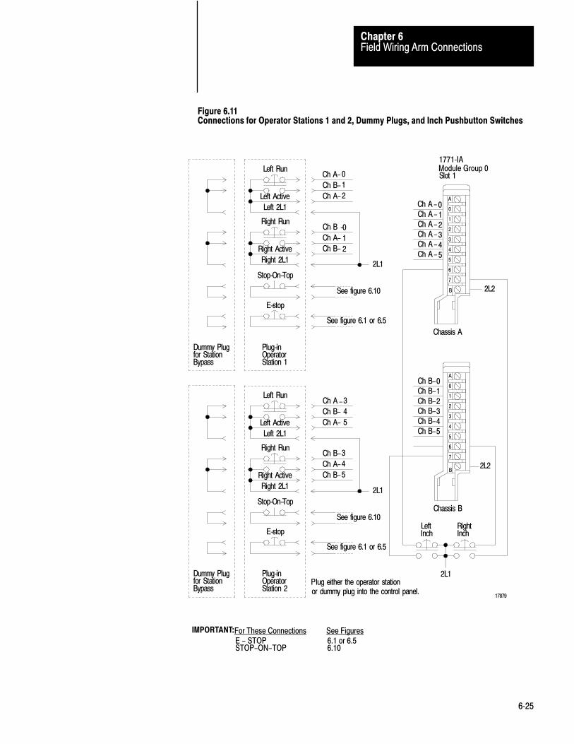
Field Wiring Arm ConnectionsChapter 6
6�25
Figure 6.11Connections for Operator Stations 1 and 2, Dummy Plugs, and Inch Pushbutton Switches
2L2
Chassis A
2L2
Chassis B
Slot 1Ch A-0
Ch B-1
Ch A-2
Left Run
Left Active
Left 2L1
Ch B -0
Ch A- 1
Ch B- 2
Right Run
Right Active
Right 2L1
Stop-On-Top
E-stop
Dummy Plugfor StationBypass
Plug-inOperatorStation 1
See figure 6.10
See figure 6.1 or 6.5
2L1
Ch A -3
Ch B- 4
Ch A- 5
Left Run
Left Active
Left 2L1
Ch B-3
Ch A-4
Ch B-5
Right Run
Right Active
Right 2L1
Stop-On-Top
E-stop
Dummy Plugfor StationBypass
Plug-inOperatorStation 2
See figure 6.10
See figure 6.1 or 6.5
2L1
Ch A-0Ch A-1Ch A-2Ch A-3Ch A-4Ch A-5
Ch B-0Ch B-1Ch B-2Ch B-3Ch B-4Ch B-5
2L1
LeftInch
RightInch
Plug either the operator stationor dummy plug into the control panel.
17879
A
0
1
2
3
4
5
6
7
A
0
1
2
3
4
5
6
7
IMPORTANT:For These Connections See FiguresE - STOPSTOP-ON-TOP
6.1 or 6.56.10
Module Group 0
B
B
1771�IA

Field Wiring Arm ConnectionsChapter 6
6�26
Figure 6.12Connections for Operator Stations 3 and 4, and Dummy Plugs
2L2
Chassis A
2L2
Chassis B
Slot 0Ch A-0
Ch B-1
Ch A-2
Left Run
Left Active
Left 2L1
Ch B-0
Ch A-1
Ch B-2
Right Run
Right Active
Right 2L1
Stop-On-Top
E-stop
Dummy Plugfor StationBypass
See figure 6.10
See figure 6.1 or 6.5
2L1
Ch A-3
Ch B-4
Ch A-5
Left Run
Left Active
Left 2L1
Ch B-3
Ch A-4
Ch B-5
Right Run
Right Active
Right 2L1
Stop-On-Top
E-stop
Dummy Plugfor StationBypass
Plug-inOperatorStation 4
See figure 6.10
See figure 6.1 or 6.5
2L1
Ch A-0
Ch A-1
Ch A-2
Ch A-3
Ch A-4
Ch A-5
Ch B-0
Ch B-1
Ch B-2
Ch B-3
Ch B-4
Ch B-5
Plug either the operator stationor dummy plug into the control panel.
17880
A
0
1
2
3
4
5
6
7
A
0
1
2
3
4
5
6
7
IMPORTANT:For These Connections See FiguresE - STOPSTOP-ON-TOP
6.1 or 6.56.10
Plug-inOperatorStation 3
B
B
1771-IAModule Group 1

Field Wiring Arm ConnectionsChapter 6
6�27
Important: When mounting RUN and INCH buttons, ensure that:
all RUN buttons and both INCH buttons are either guarded orflush-head pushbutton switches, such as Allen-Bradley Bulletin 800PPalm Operated Pushbuttons. You can operate guarded buttons only byreaching through their guard rings.
the distance between each left RUN or INCH button and itscorresponding right RUN or INCH button is great enough to allowoperation of both buttons only by both hands.
all RUN and INCH buttons are located at greater than minimum safedistance from the point of operation of your press as specified in OSHARegulations, Title 29-Labor, Chapter XVII, Section 1910.217, andANSIB11.1, section 5.3 Formulas for calculating the minimum safedistance are included.
Use the optional diagnostic binary display shown in Figure 6.13 totroubleshoot your press. Chapter 7 lists the diagnostic messages.
We recommend Allen-Bradley Small Pilot Lights, Transformer Type (cat.no. 800T-PS16R) with 1771-OA Output Modules. You may order colorcaps separately (red is standard):
Red = cat. no. 800T�N122R
Green = Cat. no. 800T�N122G
Amber = cat. no. 800T�N122A
Blue = cat. no. 800T�N122B
White = cat. no. 800T�N122W
Clear = cat. no. 800T�N122C
You may also want to order Small Pilot Light Guards (cat. no.800T-N226), to protect the caps against accidental breakage.
STOP-ON-TOP FAULT - tells an operator that the brake is faulty. If theshaft overshoots the near top position in inch, single, or continuous mode,both voting processors prohibit clutch actuation, and turn on this indicator.(See Table 5.a and Figure 6.14)
RUN WINDOW - turns on when starting the press in these modes:
single-stroke: When both RUN buttons have been pressed at onestation, other active stations have 5 seconds to press their RUN buttonsas shown by this indicator.
Optional Binary Display
Optional Indicators

Field Wiring Arm ConnectionsChapter 6
6�28
continuous: Each ON/OFF transition of the ARM CONTINUOUSbutton starts a 5-second period in which you must press all active RUNbuttons to start continuous stroking as shown by this indicator.Pressing the ARM CONTINUOUS button again within 5 seconds (afterthe transition) starts another
Important: Press the momentary ARM CONTINUOUS button less than3 seconds. Pressing it for a longer time may inhibit its function andrequire you to release and press it again.
MICRO-INCH - turns on when voting processors detect an error inmicro-inch mode and display a diagnostic message code which isdisplayed by means of the diagnostic message display. Use look-up table7.C to determine the fault or error.
You can use the micro-inch output in two ways:
to turn on the MICRO-INCH indicator to set the most significant bit in a 9-bit binary output.
Diagnostic codes for micro-inch mode are 9-bit binary (3-digit hex) with1 as the first digit (Figure 6.14). Diagnostic message codes for all othermodes are 8-bit binary (2-digit hex). (Figure 6.13)

Field Wiring Arm ConnectionsChapter 6
6�29
Figure 6.13Connections for Optional Diagnostic Message Display
2L2
2L1
Chassis A
Module Group 5Slot 1
Chassis B
12285
Bit17
Bit16
Bit15
Bit14
Bit13
Bit12
Bit11
Bit10
2L2
2L1
Bit17
Bit16
Bit15
Bit14
Bit13
Bit12
Bit11
Bit10
A
0
1
2
3
4
5
6
7
A
0
1
2
3
4
5
6
7
B
B
We recommend Allen-Bradley Small Pilot Lights,Transformer type (cat. no. 800T-PS16R).
1771-OA

Field Wiring Arm ConnectionsChapter 6
6�30
Figure 6.14Connections for Brake Fault, Run Window, and Micro�Inch Indicators
2L2
2L1
Run Window
Micro-Inch
Chassis A
Module Group 3Slot 1
2L2
2L1
Micro-Inch
Chassis B
12286
A
0
1
2
3
4
5
6
7
A
0
1
2
3
4
5
6
7
B
B
1771�OA
W recommend Allen�Bradley Small Pilot Lights,Transformer type (cat. no. 800T �PS16R).
Stop�On�Top Fault

Field Wiring Arm ConnectionsChapter 6
6�31
When you configure the lamp test feature, you can check that allindicators are working by pressing the LAMP TEST switch connected tochassis C. The clutch/brake controller energizes the outputs to thefollowing indicators while the lamp test input is on:
Module Group 5, Slot 1, Chassis A and B for the diagnostic display Module Group 3, Slot 1, Chassis A and B for BRAKE FAULT, RUN
WINDOW, and MICRO-INCH indicators.
Since hex (hexadecimal) numbers are easier than binary for people toread, you may want to display hex message codes. You may provide adevice to convert the eight-digit binary outputs of chassis A and B,module group 2, slot 1 to two-digit hex displays. Select output modulesthat provide proper voltage to the device. For assistance, contact yourlocal Allen-Bradley sales engineer or distributor.
In chapter 7, we describe other methods of displaying hex message codes.
Chassis C provides for these functions:
reset latched messages lamp test customer interlock (redundant to Figure 6.1 or 6.5) barrier guard (redundant to Figure 6.10) stop-on-top (redundant to Figures 6.11 and 6.12)
This chassis is optional because you can:
omit redundant functions use alternatives for the non-redundant functions
As alternatives, you can program the PLC to transfer the message reset bit(bit 14) and/or the lamp test bit (bit 16) to the clutch/brake modules toprovide those functions. If already using A-B’s PanelView , use thatoperator interface to implement these functions.
If you use chassis C, follow these steps:
1. Wire PLC command switches as shown in Figure 6.15
2. Include command rungs, Figure 4.6, 4.7, or 4.8.
3. Set the backplane switches of chassis C to a valid rack address foryour PLC and clutch/brake system.
Lamp Test
Inputs to Chassis C

Field Wiring Arm ConnectionsChapter 6
6�32
Chassis C can be any remote or local I/O chassis connected to your PC.Refer to sections titled “Panel Switches and Operator Stations”in chapter3, and “Configuration Rungs” in chapter 4, for additional information.
Figure 6.15Connections for Optional PLC Command Switches1
Rack 3, ModuleGroup 2
Bits 10 thru 17
2L2
2L1
Bit 13
Bit 14
Bit 15
Bit 16
Barrier Guard
Reset Latched Messages
Stop-On-Top
Lamp Tes t
Chassis C(Remote I/O Chassis)
1771-IA AC Input Module
12287
A
0
1
2
3
4
5
6
7
B
Customer Interlock
1To write the ladder program to implement the use of these switches, refer toFigure 4.6, Figure 4.7 or Figure 4.8.

Chapter
7
7�1
Troubleshooting
After you have read all previous chapters, this chapter can help you:
safely isolate and correct problems in your press system interpret diagnostic messages generated by your clutch/brake controller use the module indicators in chassis A and B while troubleshooting your
press system
This chapter explains troubleshooting techniques and refers to previouschapters. We recommend that you read the entire manual and all technicaldocumentation provided by the press manufacturer before troubleshootingany problem with your press system.
We also recommend that you adhere to the safety requirements detailed inlocal code and laws and in the following publications:
OSHA Regulations, Title 29-Labor, Chapter XVII, Section 1910.217,Mechanical Power Presses
ANSI B11.1, American National Standard for Machine Tools,Mechanical Power Presses, Construction, Care, and Use
NFPA No. 79, Electrical Standard for Metal working Machine Tools
Familiarity with this documentation makes your troubleshooting not onlysafer, but easier as well.
Use these figures and tables when troubleshooting with LED indicators
Reference Description
Figure 7.1 Location of LED indicators
Figure 7.A How to read the PM Module's ACTIVE indicator
Figure 7.B How to read the PM Module's I/O RACK FAULT andCBM FAULT indiators
Figure 7.2 How to troubleshoot with LED indicators
Chapter Objectives
Troubleshooting Considerationsand Requirements
Troubleshooting with LED's

TroubleshootingChapter 7
7�2
Figure 7.1Module Indicators for Chassis A or B
12292
ACTIVE(green)
CBMFAULT(red)
I/O RACKFAULT(red)
Output statusindicators are red.On = output
Blown fuseindicators are clear.On = blown fuse
Input Module Indicators
Input status indicators are clear. On = inputOne indicator per terminal.
1771-PM Module 1771-IA Modules 1771-OD Module
Refer to tables 7.A and 7.B
Output Module IndicatorsPM Module Indicators
Table 7.AACTIVE Indicator
If the ACTIVE indicator is blinking, identify the problem by the number of blinks. There are 2 sets of blinks:
first set of blinks short pause second set of blinks long pause
repeat continuously
Number of Blinks
1st Set 2nd Set Problem Correction
1 3 Faulty RAM Replace 1771�PM module
1 4 Faulty PROM Replace 1771�PM module
2 1 Illegal rack address Set the 1771�PM module switches as detailed in chapter 3
2 3 The 1771�PM modules contain different firmware Install 1771�PM modules with identical revision codes
3 2 Missing a 1771�PM module at power up Install and fully seat both 1771�PM modules
3 4 Illegal interrupt Cycle power Replace 1771�PM module
4 1 Firmware fault Replace 1771�PM module
4 3 Lost communications between 1771�PM modules,or watchdog timed out
Check connections between 1771�PM modules orReplace 1771�PM module

TroubleshootingChapter 7
7�3
Table 7.BI/O RACK FAULT and CBM FAULT Indicators
I/O RACKFAULT
CBMFAULT Problem Correction
On Off Intermittent electrical noise, faulty 1771�PMmodule, or shorted I/O chassis backplane
Cycle power Replace 1771�PM moduleReplace each I/O module one at a timeReplace I/O chassis
Onor OFF On
Intermittent electrical noise or faulty 1771�PMmodule
Cycle power Replace 1771�PM module
Figure 7.2Troubleshooting Flowchart for Module Indicators
Press will not run.
Are all status indicators forinputs to the 1771�IA module
off? (See Figure 7.1)
Is the mode select switch off?
All power is off.(See figure 6.1 or 6.5)
Yes
Yes Select propermode.
Does thepress run?
Yes Resumenormal
operation.No No
Check the 1771�PM module indicators. (See figure 7.1)
Are both ACTIVE indicators on?Press should run. Refer to pressbuilder's documentation.
Yes
Is either ACTIVE indicator blinking?Yes
Go to table 7.A
No
No
Is either I/O RACK FAULT indicator on?
No
Is either CBM FAULT indicator on?Yes
Go to table 7.B
No
Replace the 1771�PM module whose ACTIVE indicator is off, or check the chassispower supply.
12290
No
Is a diagnosticmessage displayed
Go to table 7.C.
Are rack addresses, racksize [1], and/or baud rateset correctly?
Yes
Yes
[ 1 ] The controller will not operate if you manually configure chassis A and B to a half rack
Warning: To guard against injury to personnel, open and lock the main power disconnect before adjusting, replacing, or repairing anymechanical or electrical component in your press system. This consists of the press, clutchbrake, controller, and all associated wiring andcontrol panels.

TroubleshootingChapter 7
7�4
Although the procedure for troubleshooting your clutch/brake controllervaries with each problem, use the following steps as a general procedure:
1. Examine Figure 7.2 and NO TAG.
2. Answer questions in Figure 7.2 and NO TAG until you see areference to another figure or table. Table 7.C lists diagnostic codes.
3. Place a bookmark at Figure 7.2 or NO TAG and go to the figure ortable that it referred to in step 2. That figure or table might containother references. Therefore you may need several bookmarks whileworking among various figures and tables throughout this manual.Table 7.D is your primary reference.
4. Isolate the problem using the guidelines in Figure 7.2, or NO TAG,Table 7.C, and other references.
5. Correct the problem.
WARNING: To guard against injury to personnel or damage toyour press, open and lock the main power disconnect to turn offall AC and DC power before: manually turning the press shaft adjusting or repairing any moving parts in your press repairing or replacing any wiring in your press system,
including any field wiring arm or cable connections replacing any electronic or electrical components, such as
clutch/brake controller and I/O modules, power supplies, orchassis
replacing blown fuses in your press system
Diagnostic codes are specific and point to the exact input or output devicethat controls PM operation. When your system is wired as outlined in thismanual, you can identify the cause of a fault as follows:
1. Review the section “Diagnostic diagnostic message codes”, below.
2. Note the diagnostic code for both PM modules
General TroubleshootingProcedure
Troubleshooting Hints

TroubleshootingChapter 7
7�5
3. Determine the input or device causing the fault from thesection/sub-section heading in Table 7.D where the fault code wastabulated and from other figures or tables referred to.
4. Interpret the messages. Was this output supposed to be on? Was thatdevice supposed to be off?
Figure 7.3Troubleshooting Flowchart for Diagnostic diagnostic message codes
Press will not run.
Is a diagnostic messagedisplayed?
See Table 7.C
Does the problem relate to aninput switch or connection?
Go to figure 7.2
Yes
No
No
12291
Does the problem relate to asolenoid or its triac?
No Take action according to Table7.C
Is a blown fuse indicator on forany 1771�OD module? (See
Figure 7.1)
Replace the fuse.
No Replace the 1771�OD module orthe solenoid. Check solenoid
wiring.
Yes
Yes
Does the status indicator for theinput to the 1771�IA module
respond correctly? (See Figure7.1)
Yes
Replace the 1771�IA module.
No Replace the input switch orcheck its wiring.
Warning: To guard against injury to personnel, open and lock the main power disconnect before adjusting, replacing, or repairing anymechanical or electrical component in your press system. This consists of the press, clutchbrake, controller, and all associated wiring andcontrol panels.
TroubleshootingChapter 7
7�6
5. Trace wire leads and/or inspect the faulted device.
If you wired the PM system in a manner other than outlined in thismanual, faults are more difficult to track. Proceed as follows:
1. Determine if the fault and corresponding diagnostic code was causedby alterations in system wiring, i.e., if the fault is a run station fault,are the run stations wired directly to the PM system or throughauxiliary chassis controlled by the programmable controller? If thelatter is the case, you should look at the programmable controller’sladder program.
2. Determine if you have an I/O problem. The PM module can onlydiagnose its own I/O level. That is, it alerts you to the exact input oroutput within the system that it “sees” as incorrect. You mustinterpret from there.
Assume that your press is running normally, then stops suddenly. For thisexample, we will follow the general troubleshooting procedure.
1. Examine Figure 7.2 and Figure 7.3.
2. The first question asked in both figures is whether a diagnosticmessage is displayed. For this example, we assume that chassis Aand B are displaying these diagnostic messages:
chassis A 0010 1001 (hex 29) chassis B is displaying 0010 1000 (hex 28)
Because your answer is yes, see Table 7.D to define the problem.
3. In Table 7.D you find that:
Binary 0010 1001 (hex 29) is a T-type (trip condition) message thattells us: Station 1 active connection is open (for alternate chassis).Check wiring. (figure 6.11).
Since chassis A is displaying this message, the alternate chassis ischassis B.
Binary 0010 1000 (hex 28) is the same message. It is for thechassis displaying the message, chassis B in this case.
Troubleshooting Example

TroubleshootingChapter 7
7�7
In Table 7.C, the numbers in parentheses are figure references. Inthis example, both messages refer to Figure 6.11. Therefore, place abookmark at Table 7.D and go to that figure.
4. Figure 6.11 shows station 2 active connections for both chassis:
Left Active connects to terminal 5 of field wiring arm for modulegroup 0, slot 1 in chassis A.
Right Active connects to terminal 5 of field wiring arm for modulegroup 0 slot 1 in chassis B.
Since you learned in step 3 that the problem relates to chassis B, you canconcentrate on the Right Active connection.
5. To further isolate the problem, place a bookmark at Figure 6.11 andreturn to Figure 7.3. The next question in this figure asks: Does theproblem relate to an input switch or connection? In this example,your answer is yes, which leads you to another question. Does thestatus indicator for the input to the 1771-IA module respondcorrectly? (See Figure 7.1).
6. Figure 7.1 shows you where to find the input status indicators. Forthis example, assume that the input status indicator in chassis B formodule group 0 slot 1, terminal 5 is off.
As shown in Figure 6.11, the Right Active connection is jumpered aslong as Plug-In Operator Station 2 is plugged in. Therefore, theindicator for Right Active should be on.
7. Return to NO TAG. Since this indicator is off, your answer is no tothe question: Does the input status indicator respond correctly?NO TAG tells you to replace the input switch or check its wiring.
8. Correct the problem after first opening and locking the main powerdisconnect. Inspect and test the Right Active connection (Figure6.11). For this example, you find a broken wire in Plug-In OperatorStation 2. Repair the broken wire then, close the main disconnect andreturn the press to normal operation.

TroubleshootingChapter 7
7�8
When the PM module detects a condition, it immediately generates thecorresponding message code. You can display diagnostic message codeswith an optional display device connected to output modules in theselocations in chassis A and B:
module group 5, slot 1 (8-bit binary code) module group 3, slot 1, bit 2 (9th bit for micro-inch)
When using micro-inch mode, diagnostic diagnostic message codes are9-digit binary (3-digit hex) rather than 8-digit binary (2-digit hex) forother diagnostic message codes. The most significant bit (bit 9) indicatesa micro-inch code. When set, 2-digit hex codes XX become 3-digit hexcodes 1XX for micro-inch.
You can display diagnostic message codes in 9-digit binary, or use anoptional binary-to-hex converter and display diagnostic message codes ineasy-to-read hexadecimal notation. No programming is required. Justinstall output modules in those locations and connect display devices(Figures 6.13 and Figures 6.14).
You can also view diagnostic message codes with an Allen-Bradleyprogramming or display terminal using the data monitor feature:
If using thisprocessor Use this device
PLC�2 family Industrial Terminal (1770�T3)Hand�held Terminal (1770�T11)
PLC�3 family Industrial Terminal (1770�T4)Data access panel on the front of the processor or1784�T45, �T47, or �T50 Programming Terminal
PLC�5 family 1784�T45 ,�T47, or �T50 Programming Terminal
PLC�5/250 1784�T45, �T47, or �T50 Programming Terminal
Display of Diagnostic MessageCodes

TroubleshootingChapter 7
7�9
PM modules detect operational and equipment faults, and indicatecorresponding diagnostic message codes for more than 250 detectedconditions. Diagnostic diagnostic message codes refer to specific inputsor outputs, such as a contact on a switch or cam. Upon detecting acondition, each PM module generates its own diagnostic code. Quicksuccession of events may cause each PM module to detect a differentcondition, one condition resulting from the other.
PM modules generate three types of diagnostic message codes accordingto the severity of the condition:
Code Type Priority Method of reset
N non�latched least Clears itself when conditions no longer exist
L latched moderate Correct the conditionPress the RESET LATCHED MSG pushbutton
L latchedfollowed by "0D"
moderate Correct the conditionRestore powerInch the press to near�top positionPush the RESET LATCHED MSG pushbuttonPress the START button
T tripped highest Correct the conditionPress the RESET LATCHED MSG pushbuttonPress the START button
Non�latched Messages (lowest priority)
Non-latched messages occur when the PM module detects an errorcondition while the press is idle (clutch/brake solenoids are OFF) and thecontrol seal relays are either open or closed. The PM module:
prevents press operation as long as the error is present
After you correct the error conditions, the PM module automatically clearsthe message and readies itself for operation. These messages are typicallyrelated to a wiring error or equipment malfunction.
Example: A broken or loose wire on the active line of Run Station 1(Figure 6.13) could cause the PM module to generate the followingmessage code:
Error 10 (Hex)Check RUN button signals. Activate or bypass the station.
Types of Diagnostic MessageCodes

TroubleshootingChapter 7
7�10
Latched Messages (medium priority)
Latched messages occur when the PM module detects error conditionswhile the press is running (clutch/brake solenoids are ON). The module:
stops press motion immediately latches ON a diagnostic message turns OFF solenoid valve triacs
(seal relays remain closed)
The latched-message condition remains until you correct the problem andpress the RESET LATCHED MSG pushbutton wired to chassis C.Typical error conditions are equipment failures or improper mechanicaladjustments.
Example: If the barrier guard switch should open while the press isrunning in continuous mode, the PM module would immediately turn OFFthe solenoid valve triacs and generate the following message code:
Error 09 (Hex)Barrier guard dropout or absent
Latched Messages Followed by �0D" (corrective intervention)
Whenever a diagnostic message code is followed by the ”0D” messagecode, the maintenance technician must reset the PM system by removingcontrol power, and then re-applying power. This forces the technician tocorrect the problem before press operation can continue.
Standard Corrective Action
Because the ”0D” message code accompanies a variety of other diagnosticmessage codes, we recommend a standard corrective action. Use it whencorrecting faults for “OD” diagnostic message codes presented in Table7.C.
Check for proper cam setting and operation.(Refer to Figure 5.1 in this manual.)
Check for bad or frozen cam contacts If more than one cam assembly is used for multi-speed press operation,
check switching of these cams. Check for proper wiring of cam switches. Check for proper wiring of I/O module swing arms.

TroubleshootingChapter 7
7�11
Re�starting the Press
You re-start the press with this procedure:
1. When the “OD” message is displayed, press ESTOP to drop the sealrelays.
Message code “50” is displayed (swingarm power dropout)
2. Press the START button.
3. Press the RESET LATCHED MSG button.
4. Select INCH mode if not already selected.
5. Inch the press to the near-top position.
Types of �OD" Diagnostic Message Codes
The “OD” diagnostic message code accompanies the following type ofdiagnostic messages.
Type of Message Hex Code
Downstroke 066 � 067
Upstroke 068 � 069
Brake or Motion Detector 072 � 079, 07A
Cam Limit SwitchNear Top Position
Transition to Downstroke
Downstroke
Transition to Near Bottom Zone
Near Bottom Zone
Transition to Upstroke
Upstroke
Transition to Near Top Position
080 � 085
086 � 089
08A � 08F
090 � 093
094 � 099
09A � 09D
09E � 09F, 0A0 � 0A3
0A4 � 0A7
Hardware or Cable 0F1 � 0F3
TroubleshootingChapter 7
7�12
Trip�condition Message (highest priority)
Trip-condition messages occur anytime the PM module detects a faultcondition that casts doubt on the system’s ability to:
measure the press’s shaft angle control power to the solenoid valve triacs
When it detects this type of fault, the PM module immediately:
stops press motion opens the seal relays
If it detects that the seal relays did not open, it
blows the main power fuses with crowbar relays
The trip-condition fault remains until you correct the problem and pressthe RESET LATCHED MSG pushbutton wired to chassis C. Typical faultconditions are due to system configuration, feedback signals, run stations,or triacs. After corrrecting the fault condition, get back into operationwith the same steps as 0D Latched Message, above.
Example: If the motion detection input (Figure 6.2) should turn ONwhile the press is operating, and you did not configure for motiondetection, the PM module would generate the following message:
Error BB (Hex)Motion detector signal present though motion detector feedback isnot configured.
Diagnostic diagnostic message codes are not queued. When the PMmodule detects multiple latched or tripped message conditions, it sends thehighest priority message code to the processor so your ladder logic canprocess it, and to pre-determined slots in its I/O chassis so output modulescan display it. When you correct the condition and press the MESSAGERESET button, the PM module sends the next highest priority messagecode if an error condition still exists. A message code of higher priorityoverrides a message code of lower priority. For error conditions of equalpriority, the PM module sends the message code corresponding to the firstdetected condition.
Message�code Priority

TroubleshootingChapter 7
7�13
If you want to maintain a record of diagnostic message codes or processthem for reasons other than display, you can write ladder logic to examinethe 9-bit binary message code that PM modules return to the processor.Do this by examining bits in the input image table corresponding to:
module group 5, slot 1 (8-binary code) module group 3, slot 1, bit 2 (9th bit for micro-inch)
For example, examine a bit as follows:
I:r5| | where r is the I/O rack number
16
If recording a history of diagnostic message codes such as stored in aFIFO stack, we suggest that you record only diagnostic message codes thatexist for longer than one second and disregard all diagnostic messagecodes resulting from transient conditions of shorter duration. This guardsagainst storing no-fault status diagnostic message codes such as generatedduring start-up.
Table 7.C explains message codes generated by PM modules.
For each message code, the table states:
type of diagnostic message the problem causing the diagnostice message to be displayed recommended corrective action
In Table 7.C we use mnemonics for cam switches for the sake of brevity asfollows:
ACAM: anti-repeat cam switch RCAM: run-on cam switch TCAM: sto-top-check cam switch
Processing Diagnostic MessageCodes
Diagnostic Message Codes(Table 7.C)

TroubleshootingChapter 7
7�14
Table 7.CDiagnostic Message Codes Associated with the "0D" Message Code
MISCELLANEOUS MESSAGES
HEX CODE
TYPE PROBLEM CORRECTIVE ACTION
01 N IMPROPER MODE SELECTION
The PM module expects to see one of the allowable pressmodes (off, inch, micro�inch, single, continuous, within 0.1 sec'safter swingarm power is sealed in, and will only allow one modeat any given time.
Check selector switch wiring in figure 6.10 and operation.Check wiring to swing�arm. Check I/O module for correctoperation.
02 N ALL STATIONS BYPASSED
In the single stroke or continuous mode, the PM will not allow thepress to cycle if all operator run stations are bypassed. At leastone station must be present. Inch and micro�inch modes willoperate with all run stations bypassed.
Check station wiring in figures 6.11 and 6.12. Checkswing�arm wiring and I/O module for proper operation.
03 N SHAFT NOT AT TOP. CAN NOT ENTER SINGLE ORCONTINUOUS MODE
The PM is selected to go into the single or continuous mode, butthe cam switches, which indicate shaft position, are telling thePM that the press is not at the top.
Check for proper cam settings in figure 5.1. Check forproper cam wiring in figure 6.9. Inch press to the topposition.
04 N AWAITING RELEASE OF ALL RUN BUTTONS FOR ENTERINGSINGLE OR CONTINUOUS MODES
Release all run buttons. Check for proper operation of allbuttons. Check button wiring in figures 6.11 and 6.12.
05 N/L MAIN MOTOR FORWARD CONTACT DROPOUT OR ABSENT
The main motor forward input needs to be on in order to entersingle or continuous modes. Once in single or continuous mode,the press will stop if that input goes off.
Check feedback contact and wiring in figure 6.10. Checkswing�arm wiring and I/O module for proper operation.
06 N ACAM OPEN, PREVENTING ENTRY INTO SINGLE ORCONTINUOUS MODE.
Check wiring of ACAM in figure 6.9 and check ACAMposition in figure 5.1.
07 N AWAITING RELEASE OF ALL STOP�ON�TOP BUTTONS FORENTERING CONTINUOUS MODE.
You must release STOP�ON�TOP buttons of all active stationsbefore the PM can switch to another mode of press operation.
Check RUN button wiring figures 6.11 and 6.12.
08 N AWAITING RELEASE OF ARM CONTINUOUS BUTTON FORENTERING CONTINUOUS MODE.
You must release the ARM CONTINUOUS button and press theRUN buttons of all active stations before the PM can switch tocontinuous mode.
Check ARM CONTINUOUS button wiring figure 6.10.
09 L BARRIER GUARD DROPOUT OR ABSENT.
Press stops operation.
Check for faulty switch, broken wire, etc. figure 6.10.

TroubleshootingChapter 7
7�15
MISCELLANEOUS MESSAGES (cont'd)
HEX CODE
TYPE PROBLEM CORRECTIVE ACTION
0A N/L PC ENABLE DROPOUT OR ABSENT
*LATCHED MESSAGEThe PC enable bit from the processor must be maintained to thePM while in any mode other than off. The PM must also see thePC enable bit maintained while switching to off mode.
*NON LATCHED MESSAGEThe PM must first see the PC enable bit go on before it sees anyrequest to change modes. If this does not happen, this messagewill occur.
When the PM is actually in the off mode, the PC enable bitmay be turned off.
This condition should be used as a status prompt thatindicates the user program has not given final permissionto enter the selected mode. Check programming infigure4.6.
0B N STOP�ON�TOP SIGNAL FROM PC PREVENTING ENTRY TOCONTINUOUS MODE.
PM module is still receiving STOP�ON�TOP command from thePC processor. This command must be absent before PM canenter continuous mode.
Check ladder logic (figure 4.6, 4.7, 4.8).
0C N AWAITING RELEASE OF INCH BUTTONS FOR ENTERINGINCH MODE.
Inch�button inputs must indicate that both inch buttons havebeen released, then pushed again before its PM Module willallow inching motion. This is the ante�tie�down feature of the PMModule. refer to figures 5.2 and 6.11.
Refer to figure 5.2. Check wiring in figure 6.11.
0D N
0E N PC RUN MODE DROPOUT OR ABSENT
PC processor is not in RUN mode, probably due toa processorfault.
Correct processor fault. Switch to RUN mode.
0F N PRESS INTERLOCK DROPOUT OR ABSENT Check wiring of press interlock switch in figure 6.1 or 6.5.
10 N CHECK RUN BUTTON SIGNALS. MAKE STATION ACTIVE ORBYPASSED.
The cactive�station input is absent, but the PM module isdetecting a change�of�state of operator RUN buttons.Check station #1 (figure 6.11).
15 N MAKE LEFT AND RIGHT ACTIVE CONNECTIONS IDENTICAL. Check station #1 (figure 6.11).
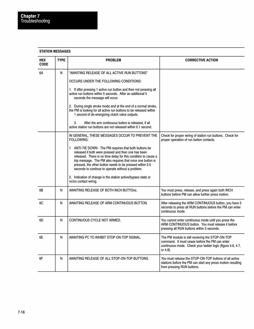
TroubleshootingChapter 7
7�16
STATION MESSAGES
HEX CODE
TYPE PROBLEM CORRECTIVE ACTION
6A N �AWAITING RELEASE OF ALL ACTIVE RUN BUTTONS"
OCCURS UNDER THE FOLLOWING CONDITIONS:
1. If after pressing 1 active run button and then not pressing allactive run buttons within 5 seconds. After an additional 5
seconds the message will occur.
2. During single stroke mode and at the end of a normal stroke,the PM is looking for all active run buttons to be released within
1 second of de�energizing clutch valve outputs.
3. After the arm continuous button is released, if allactive station run buttons are not released within 0.1 second.
IN GENERAL, THESE MESSAGES OCCUR TO PREVENT THEFOLLOWING:
1 ANTI�TIE DOWN � The PM requires that both buttons bereleased if both were pressed and then one has beenreleased. There is no time delay for this condition to cause atrip message. The PM also requires that once one button ispressed, the other button needs to be pressed within 0.5seconds to continue to operate without a problem.
2. Indication of change in the station active/bypass state ornc/no contact wiring.
Check for proper wiring of station run buttons. Check forproper operation of run button contacts.
6B N AWAITING RELEASE OF BOTH INCH BUTTOns. You must press, release, and press again both INCHbuttons before PM can allow further press motion.
6C N AWAITING RELEASE OF ARM CONTINUOUS BUTTON. After releasing the ARM CONTINUOUS button, you have 5seconds to press all RUN buttons before the PM can entercontinuous mode.
6D N CONTINUOUS CYCLE NOT ARMED. You cannot enter continuous mode until you press theARM CONTINUOUS button. You must release it beforepressing all RUN buttons within 5 seconds.
6E N AWAITING PC TO INHIBIT STOP�ON�TOP SIGNAL. The PM module is still receiving the STOP�ON�TOPcommand. It must cease before the PM can entercontinuous mode. Check your ladder logic (figure 4.6, 4.7,or 4.8).
6F N AWAITING RELEASE OF ALL STOP�ON�TOP BUTTONS. You must release the STOP�ON�TOP buttons of all activestations before the PM can start any press motion resultingfrom pressing RUN buttons.

TroubleshootingChapter 7
7�17
HEX CODE
TYPE PROBLEM CORRECTIVE ACTION
DOWNSTROKE MESSAGES
6667 (ALT)
L ANTI�REPEAT CAM SWITCH OPEN DURING DOWNSTROKE
During downstroke and before the near bottom zone, the anti�repeat cam is on, the brake monitor cam is on, and the run�oncam is off. This message will occur if the PM sees the anti�repeat cam signal go off during downstroke.
See Standard Corrective Action **
UPSTROKE MESSAGES
68069 (ALT)
L �RUN�ON CAM OPENED BEFORE SEEING THE ANTI�REPEAT CAM TRANSITION OT OFF"
Once the press is in the near bottom zone, the PM needs to seea off�on transition of the anti�repeat cam signal during the up�stroke. If the run�on cam opens before this transition, thismessage will occur.
See Standard Corrective Action **
70 N RUN BUTTON RELEASED DURING FIRST UPSTROKE INCONTINUOUS MODE. INCH TO TOP.
This message appears when you select stroke�and�a�halffor entering continuous mode you release one (or both)RUN buttons during the first upstroke.
You must enter INCH mode and inch the press to the top tocontinue normal press operation.
71 N SHAFT NEAR TOP. INCH TO TOP. You cannot enter single or continuous mode unless thepress is at proper �near top" starting position. (figure 5.1).Check CAM switch wiring. (figure 6.9).
BRAKE OR MOTION DETECTOR MESSAGES
7273
L �BRAKE OVERRUN"�BRAKE OVERRUN � INCH BACK TO TOP"
If the press has not stopped within the open window of the neartop position, this indicates that the press has traveled too far.Code 73 means that the press was in the single stroke orcontinuous mode and now must be inched back to the near topposition.
Check alignment of the run�on and brake monitor cams toconform to fig. 5.1 in the PM manual, and to assureadequate and safe stopping distance before reaching thebrake monitor cam. Check the condition of the brake.
074075
L �MOTION DETECTOR SIGNAL IS LATE OR MISSING"�MOTION DETECTOR SIGNAL DISAPPEAR ON UP�STROKE.
The motion detector input signal must come on by the time thebrake monitor cam goes off. This message will also occur whenthe press is in a up�stroke and the motion detector signaldisappears.
Check for the proper dip switch settings. Check for propercam configuration and operation. Check for proper motiondetector feedback.
076 L �MOTION DETECTOR SIGNAL DISAPPEARANCE DURINGON�HOP DOWNSTROKE"
A successful on�hop operation was achieved, and during thedown�stroke, the motion detector signal was missing for a timeperiod greater than 0.11 seconds.
Check for proper cam configuration and operation (see fig.5.1). Check for proper motion detector feedback.

TroubleshootingChapter 7
7�18
BRAKE OR MOTION DETECTOR MESSAGES (cont'd)
HEX CODE
TYPE PROBLEM CORRECTIVE ACTION
077
078
L �MOTION DETECTOR SIGNAL DISAPPEARANCE ON 2NDDOWNSTROKE"�MOTION DETECTOR SIGNAL DISAPPEARANCE DURINGCONTINUOUS CYCLE"
Proper motion detection must be seen for press operation tocontinue.
Check for proper cam configuration and operation (fig. 5.1).Check for proper motion detector feedback signal.*Requires stopping and existing continuous mode. Inch tonear top zone to start next single/continuous stroke.
079
07A
L �MOTION DETECTOR SIGNAL DISAPPEARS AT NEARBOTTOM"�MOTION DETECTOR SIGNAL DISPAPPEARS AT NEAR TOP"
The motion detector signal must come on by the time the brakemonitor cam opens in the near bottom zone, and must remain onto continue stroking. This message will also occur when thepress is in an upstroke and the motion detector signaldisappears.
Check for proper cam configuration and operation (fig. 5.1).Check for proper motion detector feedback.
07B T �MOTION DETECTOR SIGNAL COMES ON WHILE PRESS ISSTOPPED"
Check for a faulty motion detector or a shorted wirecondition. Check for proper clutch operation.
07C T �MOTION DETECTOR SIGNAL REMAINS ON AFTER PRESSSTOPS"
The motion detector signal needs to drop out within 4 secondsafter clutch solenoid outputs are de�energized.
Check for a faulty motion detector or a shorted wirecondition. Check for proper clutch operation.
080
081
082
083
L �BRAKE MONITOR AND RUN�ON CAM SWITCHES ARE BOTHCLOSED"�BRAKE MONITOR FOR THIS CHASSIS AND RUN�ON CAMFOR THE OTHER CHASSIS BOTH CLOSED"�BRAKE MONITOR FOR THE OTHER CHASSIS AND RUN�ONCAM FOR THIS CHASSIS BOTH CLOSED"�ALT BRAKE MONITOR AND RUN�ON CAM SWITCHES AREBOTH CLOSED"
There should not be any overlap of the brake monitor and run�oncam switches at the near top position.
Check for proper cam configuration and operation (See fig.5.1). Check for a faulty cam limit switch.

TroubleshootingChapter 7
7�19
BRAKE OR MOTION DETECTOR MESSAGES (cont'd)
HEX CODE
TYPE PROBLEM CORRECTIVE ACTION
084
085
L �RUN�ON CAM SWITCH CLOSED, SHOWING REVERSEMOTION"(ALT CHASSIS)
Both the run�on and brake monitor cams were off signaling thepress was in the near top position, and then the run�on camswitch signal came on again.
*Note � Can only occur if the main motor forward input is on.
Check for proper cam operation. Check for properoperation of pc logic. Check clutch operation.
CAM LIMIT SWITCH � TRANSITION TO DOWNSTROKE MESSAGES
086087
088089
L �RUN ON CAM SWITCH CLOSED"(ALT CHASSIS)
The press is in transition to down�stroke (brake monitor cam onand run�on cam off), and the run�on cam came back on.
BCAM SWITCH BOUNCED WHEN TURNING ON. CONTACTSWORN OR DIRTY.
See Standard Corrective Action **
1. Replace BCAM contacts.2. Press Reset�latched�msg PB (0D code appears)
3. Cycle swingarm power and restart press.
CAM LIMIT SWITCH � DOWNSTROKE MESSAGES
08A
08B
08C
08D
L �BRAKE MONITOR OPENED WHEN RUN�ON CAM SWITCH ISCLOSED"�LOCAL BRAKE MONITOR OPEN REMOTE RUN�ON CAMSWITCH CLOSED"�REMOTE BRAKE MONITOR OPEN LOCAL RUN�ON CAMSWITCH CLOSED"�REMOTE BRAKE MONITOR OPEN REMOTE RUN�ON CAMSWITCH CLOSED"
The PM needs to see the downstroke, near bottom, andupstroke cam conditions in order for correct opertion. Thismessage indicates that the PM saw a downstroke and then aupstroke without passing through the near bottom zone.
See Standard Corrective Action **
08E
08F
L �BRAKE MONITOR CAM SWITCH OPEN AND RUN�ON CAMSWITCH OPEN SHOWING REVERSE MOTION"(ALT CHASSIS)
During single stroke or continuous mode, only forward motion isallowed. When the press was in the downstroke, the brakemonitor cam and the run�on cam switches were on, signaling atransition from downstroke directly to the near top zone.
See Standard Corrective Action **. Also check for properclutch operation.

TroubleshootingChapter 7
7�20
CAM LIMIT SWITCH � TRANSITION TO NEAR BOTTOM ZONE MESSAGES
HEX CODE
TYPE PROBLEM CORRECTIVE ACTION
090091
L �BRAKE MONITOR CAM SWITCH OPEN"(ALT CHASSIS)
The PM logic was in a momentary zone transition state betweendownstroke and near bottom zones. Before being able to fullytransition into the near bottom zone, the brake monitor camturned off, signaling instead, a transition to the upstroke.
See Standard Corrective Action **
092093
L �RUN�ON CAM BOUNCED OR MOTION REVERSED"(ALT CHASSIS)
During single stroke or continuous mode, only forward motion isallowed. When the press is in the near bottom zone, the brakemonitor cam and the run�on cam switches are closed. The PMthen sees the run�on cams open before the brake monitoropens, signaling a reverse back to the downstroke position.
See Standard Corrective Action **. Also check for properclutch operation.
CAM LIMIT SWITCH � NEAR BOTTOM ZONE MESSAGES
094
095
096
097
L �BRAKE MONITOR AND RUN�ON CAM SWITCHES BOTHOPEN"�LOCAL BRAKE MONITOR AND REMOTE RUN�ON CAMSWITCHES BOTH OPEN"�REMOTE BRAKE MONITOR AND LOCAL RUN�ON CAMSWITCHES BOTH OPEN"(ALT CHASSIS FOR 094)
The PM is presently in the near bottom zone of the stroke (run�on and brake monitor cam switches on). This message occurswhen the PM sees an incorrect transition directly to the near topzone (run�on and brake monitor cam switches off), without goingthrough the upstroke.
See Standard Corrective Action **
098
099
L �RUN�ON CAM SWITCH OPEN SHOWING REVERSEMOTION"(ALT CHASSIS)
During single stroke or continuous mode, only forward motion isallowed. This message occurs when the press is in the nearbottom zone, and then the run�on cam switch opens before thebrake monitor cam opens, signaling reverse motion.
See Standard Corrective Action **. Also check for properclutch operation.
09A09B
L �RUN�ON CAM SWITCH OPEN"(ALT CHASSIS)
The PM logic was momentarily in a zone transition statebetween the near bottom and up�stroke zones. Before beingable to fully transition to the upstroke, the PM saw the run�oncam signal go off.
See Standard Corrective Action **

TroubleshootingChapter 7
7�21
CAM LIMIT SWITCH � NEAR BOTTOM ZONE MESSAGES (cont'd)
HEX CODE
TYPE PROBLEM CORRECTIVE ACTION
09C
09D
L �BRAKE MONITOR CAM SWITCH BOUNCED OR MOTIONREVERSED"(ALT CHASSIS)
During single stroke or continuous mode, only forward motion isallowed. This message occurs when the PM sees a transition toupstroke (run�on cam on, brake monitor cam off) and then seesthe brake monitor cam come back on, before the run�on camopens.
See Standard Corrective Action **. Also check for properclutch operation.
CAM LIMIT SWITCH � UPSTROKE MESSAGES
09E
09F
0A0
0A1
L �BRAKE MONITOR CLOSED WHEN RUN�ON CAM SWITCHOPENED"�LOCAL BRAKE MONITOR CLOSED WHEN REMOTE RUN�ONCAM SWITCH OPENED"�REMOTE BRAKE MONITOR CLOSED WHEN LOCAL RUN�ONCAM SWITCH OPENED"�REMOTE PM'S BRAKE MONITOR SIGNAL IS ON WHENREMOTE PM'S RUN�ON CAM SIGNAL IS OFF"
The PM saw that the press was in a upstroke (run�on cam onand brake monitor cam going off), and then saw an incorrectzone transition to downstroke (run�on cam off and brake monitorcam on), without going through the near top zone.
See Standard Corrective Action **
0A2
0A3
L �BRAKE MONITOR CAM SWITCH CLOSED SHOWINGREVERSE MOTION"(ALT CHASSIS)
During single stroke or continuous mode, only forward motion isallowed. The PM saw that the press was in an upstroke, andthen saw an incorrect zone transition back to the near bottomzone.
See Standard Corrective Action **. Also check for properclutch operation.
CAM LIMIT SWITCH � TRANSITION TO NEAR TOP ZONE MESSAGES
0A40A5
L �BRAKE MONITOR CAM SWITCH CLOSED"(ALT CHASSIS)
The PM logic was momentarily in a zone transition statebetween the upstroke and near top zones. Before being able tofully transition to the near top zone, the brake montior cam signalcame on, signaling instead, a zone transition to downstroke.
See Standard Corrective Action **. Also check for apossible brake problem.

TroubleshootingChapter 7
7�22
CAM LIMIT SWITCH � TRANSITION TO NEAR TOP ZONE MESSAGES (cont'd)
HEX CODE
TYPE PROBLEM CORRECTIVE ACTION
0A6
0A7
L �RUN�ON CAM SWITCH BOUNCED OR MOTION REVERSED"(ALT CHASSIS)
During single stroke or continuous mode, only forward motion isallowed. The PM saw that it was in transition to the near topzone, and then saw the run�on cam input come back on possibleshowing reverse motion.
See Standard Corrective Action **. Also check for properclutch operation.
DIAGNOSTIC MESSAGES
F1 L �LOST COMMUNICATION BETWEEN 1771�PM MODULES" Check rack communication cable. Cycle rack power.
F2 L �LOST COMMUNICATION TO PROGRAMMABLECONTROLLER"
Check rack communication cable. Check for proper rackand scanner configuration. Check for potential electricalnoise problem. Cycle rack power.
AA L ALL CAM SWITCHES TURN OFF. 1. Disconnected ground to 1771�IA module. Disconnectedpower to CAM switches,. disconnected swingarm to1771�IA. bad 1771�IA module.2. Press Reset�latched�msg PB.
A8 N CAM SWITCHES CANNOT DETECT SHAFT POSITION. Same as AA except not a latched�message code.
A9 N ALL CAM SWITCHES ARE OFF. NEVER DETECTED ON. Same as A8.

TroubleshootingChapter 7
7�23
The complete diagnostic message table is divided into sections andsubsections common to a device, operating condition, or hardwarecondition to assist your troubleshooting. When a diagnostic condition isdetected and a message code is displayed, look for the problem in thesection/subsection in which the message code is tabulated. Table 7.D alsorefers you to figures and/or tables to assist you in determining the cause ofthe fault condition.
We present a complete list of diagnostic message codes to assist introubleshooting. They are grouped as follows:
Press operation Stations 1, 2, 3, and 4 Inch button
Valve stem inputs not configured Downstroke fault Upstroke fault Fault in setup for continuous mode Faulty brake or motion detector Faulty cam limit switch General faults Configuration error Motion detector and pressure switch faults Triac faults Fault in valve stem feedback Hardware or cable faults Micro-inch diagnostic codes
Complete Listing of diagnostic message codes

TroubleshootingChapter 7
7�24
Table 7.DDiagnostic Messages
Diagnostic message codes are displayed by indicators connected to module group 5, slot 1 (figure 6.18), or bydisplaying the corresponding data table word using the industrial terminal.
Use this table in conjunction with figure 7.1 and figure references shown in parentheses.
Type of MessageN = Non�latchedL = LatchedT = TripCondition
CodeP = at Power�upAlt = Alternate chassisEthr = Either chassisTop = Top chassisBot = Bottom chassis
HexCode
Type Diagnostic Message (figure References)
Press Operation Inhibited
01 N Improper mode selection (6.12)
02 N All stations bypassed. (6.13 thru 6.16)
03 N Shaft not near top. Can not enter single or continuous mode. (5.1, 6.11)
04 N Awaiting release of all RUN buttons for entering single or continuous mode. (6.13 thru 6.16)
05 N Main motor forward dropout or absent (6.12)
06 N Anti�repeat cam switch open, preventing entry to single or continuous mode (5.5, 6.11)
07 N Awaiting release of all STOP�ON�TOP buttons for entering continuous mode. (5.5, 6.12)
08 N Awaiting release of ARM CONTINUOUS button for entering continuous mode.(5.5, 6.12)
09 N Barrier guard dropout or absent. (5.5, 6.12)
0A N PC enable dropout or absent. (4.5, 4.7)
0B N Stop�on�top signal from PC preventing entry to continuous mode. (4.5, 4.7)
0C N Awaiting release of INCH buttons for entering inch mode. (5.2, 6.13)
0D N Awaiting solenoid power to reset stop condition. Press E�STOP, then START buttons. (6.1, 6.6)
0E N PC run mode dropout or absent.
0F N Press interlock dropout or absent. (6.2, 6.7)
Station 1 (Figure 6.13)
10 N Check RUN button signals. Make station active or bypassed.
11 N RUN button not released. Check (NO) contacts.
12Alt N RUN button not released. Check (NO) contacts.

TroubleshootingChapter 7
7�25
Diagnostic message codes are displayed by indicators connected to module group 5, slot 1 (figure 6.18), or bydisplaying the corresponding data table word using the industrial terminal.
Use this table in conjunction with figure 7.1 and figure references shown in parentheses.
Type of MessageN = Non�latchedL = LatchedT = TripCondition
CodeP = at Power�upAlt = Alternate chassisEthr = Either chassisTop = Top chassisBot = Bottom chassis
HexCode
Diagnostic Message (figure References)Type
13 N RUN button not released. Check (NC) contacts.
14Alt N RUN button not released. Check (NC) contacts.
15 P N Make left and right active connections identical.
16 P N (NC) RUN button is open. Check button or wiring.
17 P N (NO) RUN button is shorted. Check button or wiring.
18 T Active input changed from closed to open. Check wiring.
19 Alt T Active input changed from closed to open. Check wiring.
1A T (NC) RUN button bypass is open. Check wiring
1B Alt T (NC) RUN button bypass is open. Check wiring
1C T (NO) RUN button bypass is open. Check wiring
1D Alt T (NO) RUN button bypass is open. Check wiring
1E Not Used.
1F Not Used
Station 2(Figure 6.14)
20 N Check RUN button signals. Make station active or bypassed.
21 N RUN button not released. Check (NO) contacts.
22 Alt N RUN button not released. Check (NO) contacts.
23 N RUN button not released. Check (NC) contacts.
24 Alt N RUN button not released. Check (NC) contacts.
25 P N Make left and right active connections identical.
26 P N (NC) RUN button is open. Check button or wiring.
27 P N (NO) RUN button is shorted. Check button or wiring.

TroubleshootingChapter 7
7�26
Diagnostic message codes are displayed by indicators connected to module group 5, slot 1 (figure 6.18), or bydisplaying the corresponding data table word using the industrial terminal.
Use this table in conjunction with figure 7.1 and figure references shown in parentheses.
Type of MessageN = Non�latchedL = LatchedT = TripCondition
CodeP = at Power�upAlt = Alternate chassisEthr = Either chassisTop = Top chassisBot = Bottom chassis
HexCode
Diagnostic Message (figure References)Type
28 T Active input changed from closed to open. Check wiring.
29 Alt T Active input changed from closed to open. Check wiring.
2A T (NC) RUN button bypass is open. Check wiring
2B Alt T (NC) RUN button bypass is open. Check wiring
2C T (NO) RUN button bypass is open. Check wiring
2D Alt T (NO) RUN button bypass is open. Check wiring
2E Not Used.
2F Not Used
Station 3(Figure 6.15)
30 N Check configuration of RUN button signals. Make station active or bypassed
31 N RUN button not released. Check (NO) contacts.
32 Alt N RUN button not released. Check (NO) contacts.
33 N RUN button not released. Check (NC) contacts.
34 Alt N RUN button not released. Check (NC) contacts.
35 P N Make left and right active connections identical.
36 P N (NC) RUN button is open. Check button or wiring.
37 P N (NO) RUN button is shorted. Check button or wiring.
38 T Active input changed from closed to open. Check wiring.
39 Alt T Active input changed from closed to open. Check wiring.
3A T (NC) RUN button bypass is open. Check wiring
3B Alt T (NC) RUN button bypass is open. Check wiring
3C T (NO) RUN button bypass is open. Check wiring
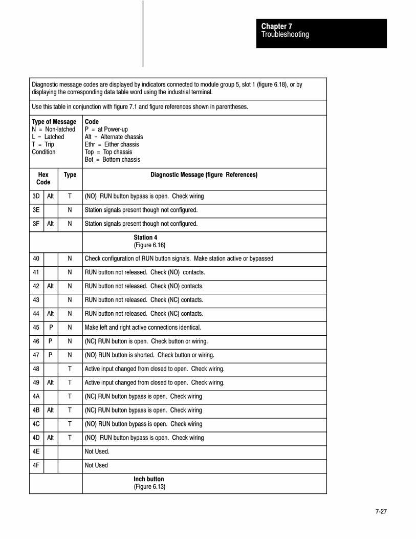
TroubleshootingChapter 7
7�27
Diagnostic message codes are displayed by indicators connected to module group 5, slot 1 (figure 6.18), or bydisplaying the corresponding data table word using the industrial terminal.
Use this table in conjunction with figure 7.1 and figure references shown in parentheses.
Type of MessageN = Non�latchedL = LatchedT = TripCondition
CodeP = at Power�upAlt = Alternate chassisEthr = Either chassisTop = Top chassisBot = Bottom chassis
HexCode
Diagnostic Message (figure References)Type
3D Alt T (NO) RUN button bypass is open. Check wiring
3E N Station signals present though not configured.
3F Alt N Station signals present though not configured.
Station 4(Figure 6.16)
40 N Check configuration of RUN button signals. Make station active or bypassed
41 N RUN button not released. Check (NO) contacts.
42 Alt N RUN button not released. Check (NO) contacts.
43 N RUN button not released. Check (NC) contacts.
44 Alt N RUN button not released. Check (NC) contacts.
45 P N Make left and right active connections identical.
46 P N (NC) RUN button is open. Check button or wiring.
47 P N (NO) RUN button is shorted. Check button or wiring.
48 T Active input changed from closed to open. Check wiring.
49 Alt T Active input changed from closed to open. Check wiring.
4A T (NC) RUN button bypass is open. Check wiring
4B Alt T (NC) RUN button bypass is open. Check wiring
4C T (NO) RUN button bypass is open. Check wiring
4D Alt T (NO) RUN button bypass is open. Check wiring
4E Not Used.
4F Not Used
Inch button(Figure 6.13)

TroubleshootingChapter 7
7�28
Diagnostic message codes are displayed by indicators connected to module group 5, slot 1 (figure 6.18), or bydisplaying the corresponding data table word using the industrial terminal.
Use this table in conjunction with figure 7.1 and figure references shown in parentheses.
Type of MessageN = Non�latchedL = LatchedT = TripCondition
CodeP = at Power�upAlt = Alternate chassisEthr = Either chassisTop = Top chassisBot = Bottom chassis
HexCode
Diagnostic Message (figure References)Type
50 Swingarm power absent
51 N INCH button not released. Check (NO) contacts.
52 Alt N INCH button not released. Check (NO) contacts.
53 N INCH button not released. Check (NC) contacts.
54 Alt N INCH button not released. Check (NC) contacts.
55 P N INCH button not released. Check (NC) contacts.
56 P,Alt
N INCH button not released. Check (NC) contacts.
57 P N INCH button not released. Check (NC) contacts.
58 P,Alt
N INCH button is not released. Check (NO) contacts).
59 Not used.
Valve Stem Inputs Not Configured
5A T Main valve stem input is present but not configured. (6.17)
5B Alt T Main valve stem input is present but not configured. (6.17)
5C T Auxiliary valve stem input is present but not configured. (6.17)
5D Alt T Auxiliary valve stem input is present but not configured. (6.17)
5E T Dump valve stem input is present but no configured. (6.4, 6.9)
5F Alt T Dump valve stem input is present but no cinfigured. (6.4, 6.9)
Downstroke Fault
60 L RUN button in station 1 released too late in the downstroke.(5.3,5.6,6.13)
61 L RUN button in station 1 released too late in the downstroke.(5.3,5.6,6.13)
62 L RUN button in station 1 released too late in the downstroke.(5.3,5.6,6.13)

TroubleshootingChapter 7
7�29
diagnostic message codes are displayed by indicators connected to module group 5, slot 1 (figure 6.18), or by displaying the correspondingdata table word using the industrial terminal.
Use this table in conjunction with figure 7.1 and figure references shown in parentheses.
Type of MessageN = Non�latchedL = LatchedT = Trip Condition
CodeP = at Power�upAlt = Alternate chassisEthr = Either chassisTop = Top chassisBot = Bottom chassis
Binary Hex Type Code Diagnostic Message (figure References)
0110 0011 63 L RUN button in station 1 released too late in the downstroke.(5.3,5.6,6.13)
0110 0100 64 N Anti�repeat cam switch open while awaiting start or restart of downstroke (6.11)
0110 0101 65 N Alt Anti�repeat cam switch open while awaiting start or restart of downstroke (6.11)
0110 0110 66 L Anti�repeat cam switch open during downstroke (6.11)
0110 0111 67 L Alt Anti�repeat cam switch open during downstroke (6.11)
Upstroke Fault
0110 1000 68 L Run�on cam switch opened too soon, or anti�repeat cam switch closed continuously. (6.11)
0110 1001 69 L Alt Run�on cam switch opened too soon, or anti�repeat cam switch closed continuously. (6.11)
0110 1010 6A N Awaiting release of all RUN button. (6.13 thru 6.16)
0110 1011 6B N Awaiting release of all RUN button. (6.13 thru 6.16)
Fault in Set�up for Continuous Mode
0110 1100 6C N Awaiting release of ARM CONTINUOUS button. (5.5, 6.12)
0110 1101 6D N Continuous cycle not armed. (5.5)
0110 1110 6E N Awaiting PC to inhibit stop�on�top signal. (4.5, 4.7)
0110 1111 6F N Awaiting release of all STOP�ON�TOP buttons. (6.12)
0111 0000 70 N RUN button released during first upstroke in continuous mode. Inch to op. (5.7,6.13 thru 6.16)
0111 0001 71 N Shaft not near top. Inch to top. (5.1)
Faulty Brake or Motion Detector
0111 0010 72 N Faulty brake. reset swingarm power. (5.2, 5.4, 5.8)
0111 0011 73 N Faulty brake. reset swingarm power and inch to top. (5.2, 5.4, 5.8)
0111 0100 74 L Motion detector signal missing at start of downstroke. (5.1, 6.17)
0111 0101 75 L Motion detector signal missing during upstroke. (5.1, 6.17)

TroubleshootingChapter 7
7�30
diagnostic message codes are displayed by indicators connected to module group 5, slot 1 (figure 6.18), or by displaying the correspondingdata table word using the industrial terminal.
Use this table in conjunction with figure 7.1 and figure references shown in parentheses.
Type of MessageN = Non�latchedL = LatchedT = Trip Condition
CodeP = at Power�upAlt = Alternate chassisEthr = Either chassisTop = Top chassisBot = Bottom chassis
Binary Diagnostic Message (figure References)CodeTypeHex
0111 0110 76 L Motion detector signal missing during on�the�hop downstroke. (5.1, 6.17)
0111 0111 77 L Motion detector signal missing during second downstroke. (5.1, 6.17)
0111 1000 78 L Motion detector signal missing during continuous cycle. (5.1, 6.17)
0111 1001 79 L Motion detector signal missing at near bottom. (5.1, 6.17)
0111 1010 7A L Motion detector signal missing at near top. (5.1, 6.17)
0111 1011 7B T Motion detector signal comes on while press is stopped. (6.17)
0111 1100 7C T Motion detector signal remains on after press stops. (6.17)
0111 1101 7D Not used.
0111 1110 7E Not used
0111 1111 7F Not used
Faulty Cam Limit Switch
Near Top Position(Figures 5.1, 6.11)
1000 0000 80 L Brake monitor and run�on cam switches both closed.
1000 0001 81 L Brake monitor for this chassis and run�on cam switch for the other chassis both closed.
1000 0010 82 L Brake monitor for this chassis and run�on cam switch for the other chassis both closed.
1000 0011 83 L Alt Brake monitor and run�on cam switches both closed.
1000 0100 84 L Run�on cam switch closed, showing reverse motion.
1000 0101 85 L Alt Run�on cam switch closed, showing reverse motion.
Transition to Downstroke(Figures 5.1, 6.11)
1000 0110 86 L Run�on cam switch closed.
1000 0111 87 L Alt Run�on cam switch closed.

TroubleshootingChapter 7
7�31
diagnostic message codes are displayed by indicators connected to module group 5, slot 1 (figure 6.18), or by displaying the correspondingdata table word using the industrial terminal.
Use this table in conjunction with figure 7.1 and figure references shown in parentheses.
Type of MessageN = Non�latchedL = LatchedT = Trip Condition
CodeP = at Power�upAlt = Alternate chassisEthr = Either chassisTop = Top chassisBot = Bottom chassis
Binary Hex Type Code Diagnostic Message (figure References)
1000 1000 88 L Brake monitor cam switch bounced or motion reversed.
1000 1001 89 L Alt Brake monitor cam switch bounced or motion reversed.
Downstroke(Figures 5.1, 6.11)
10001010 8A L Brake monitor open when run�on cam switch is closed.
1000 1011 8B L Brake monitor for this chassis open when run�on cam switch for the other chassis is closed.
1000 1100 8C L Brake monitor for this chassis open when run�on cam switch for the other chassis is closed.
1000 1101 8D L Alt Brake monitor open when run�on cam switch is closed.
1000 1110 8E L Brake monitor can switch open, showing reverse motion.
1000 1111 8F L Alt Brake monitor can switch open, showing reverse motion.
Transition to Near Bottom Zone(Figures 5.1, 6.11)
1001 0000 90 L Brake monitor cam switch open.
1001 0001 91 L Alt Brake monitor cam switch open.
1001 0010 92 L Run�on cam switch bounced or motion reversed.
1001 0011 93 L Alt Run�on cam switch bounced or motion reversed.
Near Bottom Zone(Figures 5.1, 6.11)
1001 0100 94 L Brake monitor and run�on cam switches both open.
1001 0101 95 L Brake monitor for this chassis and run�on cam switch for the other chassis both open.
1001 0110 96 L Brake monitor for this chassis and run�on cam switch for the other chassis both open.
1001 0111 97 L Alt Brake monitor and run�on cam switches both open.
1001 1000 98 L Run�on cam switch open, showing reverse motion.
1001 1001 99 L Alt Run�on cam switch open, showing reverse motion.

TroubleshootingChapter 7
7�32
diagnostic message codes are displayed by indicators connected to module group 5, slot 1 (figure 6.18), or by displaying the correspondingdata table word using the industrial terminal.
Use this table in conjunction with figure 7.1 and figure references shown in parentheses.
Type of MessageN = Non�latchedL = LatchedT = Trip Condition
CodeP = at Power�upAlt = Alternate chassisEthr = Either chassisTop = Top chassisBot = Bottom chassis
Binary Diagnostic Message (figure References)CodeTypeHex
Transition to Upstroke(Figures 5.1, 6.11)
1001 1010 9A L Run�on cam switch open.
1001 1011 9B L Alt Run�on cam switch open.
1001 1100 9C L Brake monitor cam switch bounced or motion reversed.
1001 1101 9D L Alt Brake monitor cam switch bounced or motion reversed.
Upstroke(Figures 5.1, 6.11)
1001 1110 9E L Brake monitor closed when run�on cam switch opened.
1001 1111 9F L Brake monitor for this chassis closed when run�on cam switch for the other chassis is open.
1010 0000 A0 L Brake monitor for this chassis closed when run�on cam switch for the other chassis is open.
1010 0001 A1 L Alt Brake monitor closed when run�on cam switch is open.
1010 0010 A2 L Brake monitor cam switch closed, showing reverse motion.
1010 0011 A3 L Alt Brake monitor cam switch closed, showing reverse motion.
Transition to Near Top Zone(Figures 5.1, 6.11)
1010 0100 A4 L Brake monitor cam switch closed.
1010 0101 A5 L Alt Brake monitor cam switch closed.
1010 0110 A6 L Run�on cam switch bounced or motion reversed.
1010 0111 A7 L Alt Run�on cam switch bounced or motion reversed.

TroubleshootingChapter 7
7�33
diagnostic message codes are displayed by indicators connected to module group 5, slot 1 (figure 6.18), or by displaying the correspondingdata table word using the industrial terminal.
Use this table in conjunction with figure 7.1 and figure references shown in parentheses.
Type of MessageN = Non�latchedL = LatchedT = Trip Condition
CodeP = at Power�upAlt = Alternate chassisEthr = Either chassisTop = Top chassisBot = Bottom chassis
Binary Hex Type Code Diagnostic Message (figure References)
1011 1100 BC T Air pressure signal present though air pressure feedback is not configured.
1011 1101 BD T Air pressure signal on when triacs are off.
1011 1110 BE T Air pressure signal on when triacs are on.
1011 1111 BF T Air pressure signal remains after triacs turn off.
Triac Fault
1100 0000 C0 T Ethr Triac 0 on when commanded off. 1
1100 0001 C1 T Ethr Triac 1 on when commanded off. 1
1100 0010 C2 T Ethr Triac 2 on when commanded off. 1
1100 0011 C3 T Ethr Triac 3 on when commanded off. 1
1100 0100 C4 T Ethr Triac 6 on when commanded off. 1
1100 0101 C5 T Ehtr Triac 7 on when commanded off. 1
1100 0110 C6 T Bot Triac 0 on when commanded off. 1
1100 0111 C7 T Bot Triac 1 on when commanded off. 1
1100 1000 C8 T Bot Triac 2 on when commanded off. 1
1100 1001 C9 T Bot Triac 3 on when commanded off. 1
1100 1010 CA T Bot Triac 6 on when commanded off. 1
1100 1011 CB T Bot Triac 7 on when commanded off. 1
1100 1100 CC T Top Triac 0 off when commanded off. 1
1100 1101 CD T Top Triac 1 off when commanded off. 1
1100 1110 CE T Top Triac 2 off when commanded off. 1
1100 1111 CF T Top Triac 3 off when commanded off. 1
1101 0000 D0 T Top Triac 6 off when commanded on. 1

TroubleshootingChapter 7
7�34
diagnostic message codes are displayed by indicators connected to module group 5, slot 1 (figure 6.18), or by displaying the correspondingdata table word using the industrial terminal.
Use this table in conjunction with figure 7.1 and figure references shown in parentheses.
Type of MessageN = Non�latchedL = LatchedT = Trip Condition
CodeP = at Power�upAlt = Alternate chassisEthr = Either chassisTop = Top chassisBot = Bottom chassis
Binary Diagnostic Message (figure References)CodeTypeHex
1101 0001 D1 T Top Triac 7 off when commanded on. 1
1101 0010 D2 T Ethr Triac 0 off when commanded on. 1
1101 0011 D3 T Ethr Triac 1 off when commanded on. 1
1101 0100 D4 T Ethr Triac 2 off when commanded on. 1
1101 0101 D5 T Ethr Triac 3 off when commanded on. 1
1101 0110 D6 T Ethr Triac 6 off when commanded on. 1
1101 0111 D7 T Ethr Triac 7 off when commanded on. 1
1101 1000 D8 T Top Triac 0 remains on after turned off. 1
1101 1001 D9 T Top Triac 1 remains on after turned off. 1
1101 1010 DA T Top Triac 2 remains on after turned off. 1
1101 1011 DB T Top Triac 3 remains on after turned off. 1
1101 1100 DC T Top Triac 6 remains on after turned off. 1
1101 1101 DD T Top Triac 7 remains on after turned off. 1
Fault in Valve Stem Feedback
1101 1110 DE T Main valve stem signal on when triacs are off. 1
1101 1111 DF T Alt Main valve stem signal on when triacs are off. 1
1110 0000 E0 T Aux. valve stem signal on when triacs are off. 1
1110 0001 E1 T Alt Aux. valve stem signal on when triacs are off. 1
1110 0010 E2 T Dump valve stem signal on when traics are off. 1
1110 0011 E3 T Alt Dump valve stem signal on when traics are off. 1
1110 0100 E4 T Main valve stem signal off when triacs are on. 1
1110 0101 E5 T Alt Main valve stem signal off when triacs are on. 1

TroubleshootingChapter 7
7�35
diagnostic message codes are displayed by indicators connected to module group 5, slot 1 (figure 6.18), or by displaying the correspondingdata table word using the industrial terminal.
Use this table in conjunction with figure 7.1 and figure references shown in parentheses.
Type of MessageN = Non�latchedL = LatchedT = Trip Condition
CodeP = at Power�upAlt = Alternate chassisEthr = Either chassisTop = Top chassisBot = Bottom chassis
Binary Diagnostic Message (figure References)CodeTypeHex
1110 0110 E6 T Aux. valve stem signal off when triacs are on. 1
1110 0111 E7 T Alt Aux. valve stem signal off when triacs are on. 1
1110 1000 E8 T Dump valve stem signal off when traics are on. 1
1110 1001 E9 T Alt Dump valve stem signal off when traics are on. 1
1110 1010 EA T Main valve stem signal remains on after triacs turn off. 1
1110 1011 EB T Alt Main valve stem signal remains on after triacs turn off. 1
1110 1100 EC T Aux. valve stem signal remain on after triacs turn off. 1
1110 1101 ED T Alt Aux. valve stem signal remain on after triacs turn off. 1
1110 1110 EE T Dump valve stem signal remains on after traics tuirn off. 1
1110 1111 EF T Alt Dump valve stem signal remains on after traics tuirn off. 1
Hardware or Cable Fault
1111 0000 F0 T Alt Chassis power tripped or chassis restarted. (6.1, 6.6)
1111 0001 F1 L Lost communications between 1771�PM modules. Reset latched message, check cables, orcycle power. (3.3)
1111 0010 F2 L Lost communications with PC. Reset latched mesage, check cables, or cycle power. (3.3)
1111 0011 F3 L Alt Lost communications with PC. Reset latched mesage, check cables, or cycle power. (3.3)
1111 0100 F4 N Lost communications between 1771�PM modules. 2
1111 0101 F5 N Hardware fault in 1771�PM module. Replace it.
1111 0110 F6 N Turn off backplane switch 1. (3.4)
1111 0111 F7 N Hardware fault in 1771�PM module. 2
1111 1000 F8 N Not used
1111 1001 F9 N Hardware fault in 1771�PM module. 2
1111 1010 FA N 1771�PM modules must be same revision.
1111 1011 FB N Hardware fault in 1771�PM module. Replace it.

TroubleshootingChapter 7
7�36
diagnostic message codes are displayed by indicators connected to module group 5, slot 1 (figure 6.18), or by displaying the correspondingdata table word using the industrial terminal.
Use this table in conjunction with figure 7.1 and figure references shown in parentheses.
Type of MessageN = Non�latchedL = LatchedT = Trip Condition
CodeP = at Power�upAlt = Alternate chassisEthr = Either chassisTop = Top chassisBot = Bottom chassis
Binary Diagnostic Message (figure References)CodeTypeHex
1111 1100 FC N Backplane error. Replace chassis. 2
1111 1101 FD N Hardware fault in 1771�PM module. 2
1111 1110 FE N Hardware fault in 1771�PM module. 2
1111 1111 FF N Power�up other 1771�PM module.
Micro�inch Diagnostic Codes(Examine module group 3, slot 1, bit 2, chassis A and B for MSB)
1 0101 1010 15A T Micro�inch valve stem input is present though not configured.
1 0101 1011 15B T Alt Micro�inch valve stem input is present though not configured.
1 1011 1100 1BC T Micro�inch clutch pressure input is present though not configured.
1 1011 1101 1BD T Micro�inch clutch pressure input is present when triacs are off.
1 1011 1110 1BE T Micro�inch clutch pressure input is off when triacs are on.
1 1011 1111 1BF T Micro�inch clutch pressure input remains on after triacs turn off.
1 1100 0000 1C0 T Ethr Triac 8 is on when commanded off.
1 1100 0001 1C1 T Ethr Triac 9 is on when commanded off.
1 1100 0110 1C6 T Bot Triac 8 is on when commanded off.
1 1100 0111 1C7 T Bot Triac 9 is on when commanded off.
1 1100 1100 1CC T Top Triac 8 is off when commanded on.
1 1100 1101 1CD T Top Triac 9 is off when commanded on.
1 1101 0010 1D2 T Ethr Triac 8 is off when commanded on.
1 1101 0011 1D3 T Ethr Triac is off when commanded on.

TroubleshootingChapter 7
7�37
diagnostic message codes are displayed by indicators connected to module group 5, slot 1 (figure 6.18), or by displaying the correspondingdata table word using the industrial terminal.
Use this table in conjunction with figure 7.1 and figure references shown in parentheses.
Type of MessageN = Non�latchedL = LatchedT = Trip Condition
CodeP = at Power�upAlt = Alternate chassisEthr = Either chassisTop = Top chassisBot = Bottom chassis
Binary Diagnostic Message (figure References)CodeTypeHex
1 1101 1000 1D8 T Ethr Triac 8 remains on after triacs turn off.
1 1101 1001 1D9 T Ethr Triac 9 remains on after triacs turn off.
1 1101 1110 1DE T Micro�inch valve stem input is on when triacs are off.
1 1101 1111 1DF T Alt Micro�inch valve stem input is on when triacs are off.
1 1110 0100 1E4 T Micro�inch valve stem input is off when triacs are on.
1 1110 0101 1E5 T Alt Micro�inch valve stem input is off when triacs are on.
1 1110 1010 1EA T Micro�inch valve stem input remains on after triacs turn off.
1 1110 1000 1E8 T Alt Micro�inch valve stem input remains on after triacs turn off.
1 1111 1111 1FF N Lamp test in progress
2 Refer to ACTIVE indicator (table 7.A) or FAULT indicators (table 7.B).
Now that you have read this chapter, you should have a general idea ofhow to safely troubleshoot your press system. This chapter showed youhow to interpret the diagnostic diagnostic message codes and statusindicators of your clutch/brake controller. It also referred you to theassociated connection diagrams for locating the fault.
Summary
Diagnostic diagnostic messagecodes in Table 7.C

TroubleshootingChapter 7
7�38
Diagnostic message codes are displayed by indicators connected to module group 5, slot 1 (figure 6.18), or by displaying the correspondingdata table word using the industrial terminal.
Use this table in conjunction with figure 7.1 and figure references shown in parentheses.
Type of MessageN = Non�latchedL = LatchedT = Trip Condition
CodeP = at Power�upAlt = Alternate chassisEthr = Either chassisTop = Top chassisBot = Bottom chassis
Binary Hex Type Code Diagnostic Message (figure References)
Other Cam Limit Switch Faults(Figures 5.1, 6.11)
1010 1000 A8 N P Cam switches cannot determine shaft position. Inch to top.
1010 1001 A9 N P All cam switches are open.
1010 1010 AA L Cam switches cannot determine shaft position. Inch to top.
General Faults
1010 1011 AB N Not used.
1010 1100 AC L Crowbar test input is ON. Check wiring of crowbar testt circuit
1010 1101 AD N Awaiting turn off of crowbar relay test.
1010 1110 AE N Awaiting turn off of crowbar relay test.
1010 1111 AF N Awaiting solenoid power.
Configuration Error
1011 0000 B0 N Alt Configuration error in alternate module. Configure it correctly or match inputs to yourconfiguration.
1011 0001 B1 N Turn off backplane switch 1.
1011 0010 B2 N Stations 3 and 4 configuration bitr and backplane switch mismatched
1011 0011 B3 N Motion detector configuration bit and backplan switch mismatched.
1011 0100 B4 N Valve stem switch configuration bit and backplance switch mismatched.
1011 0101 B5 N Air pressure switch configuration bit and backplane switch mismatched.
1011 0110 B6 N Ungrounded/grounded AC power configuration bit and backplane switch mismatched.
1011 0111 B7 N On�the�hop configuration bit and backplane switch mismatched.
1011 1000 B8 N Stroke�and�a�half configuration bit and backplane switch mismatched.
1011 1001 B9 N Dump valve configuration bit disagrees with corresponding I/O modules in chassis.
1011 1010 BA N An I/O input module is missing.

TroubleshootingChapter 7
7�39
Diagnostic message codes are displayed by indicators connected to module group 5, slot 1 (figure 6.18), or by displaying the correspondingdata table word using the industrial terminal.
Use this table in conjunction with figure 7.1 and figure references shown in parentheses.
Type of MessageN = Non�latchedL = LatchedT = Trip Condition
CodeP = at Power�upAlt = Alternate chassisEthr = Either chassisTop = Top chassisBot = Bottom chassis
Binary Diagnostic Message (figure References)CodeTypeHex
Motion Detector and Pressure Switch Faults(Figures 3.4, 6.17)
1011 1011 BB T Motion detector signal present though motion detector feedback is not configured.
1011 1100 BC T Air pressure signal present though air pressure feedback is not configured.
1011 1101 BD T Air pressure signal on when triacs are off.
1011 1110 BE T Air pressure signal on when triacs are on.
1011 1111 BF T Air pressure signal remains after triacs turn off.
Appendix
A
A�1
Bit Monitoring Addresses
Use the addresses in the following tables to monitor press operation.Address digits a, b, and c are rack address digits. Assign them as requiredby your application. For PLC–2/20, –2/30 processors, rack addresses are1 thru 7. For PLC–3 processors, rack addresses are 00 thru 77. Refer toRack Addresses of Chassis A and B, chapter 3.10 for further information.

Bit Monitoring AddressAppendix A
A�2
Module Group 0
Slot 0, 1771-IA, Figure 6.10
Addresses
Term. Function PLC-2/30 Chassis A B
PLC-3 Chassis A B
0 Selector switch OFF position 1a0/00 1b0/00 10ab0/00 10ac0/00
1 Selector switch INCH position 1a0/01 1b0/01 10ab0/01 10ac0/01
2 Selector switch SINGLE position 1a0/02 1b0/02 10ab0/02 10ac0/02
3 Selector switch CONTINUOUS position 1a0/03 1b0/03 10ab0/03 10ac0/03
4 Main motor forward (NO) contactor 1a0/04 1b0/04 10ab0/04 10ac0/04
5 Barrier guard in position (NO) limit sw. 1a0/05 1b0/05 10ab0/05 10ac0/05
6 Stop-on-top (NC) contacts 1a0/06 1b0/06 10ab0/06 10ac0/06
7 Arm continuous (NO) contacts 1a0/07 1b0/07 10ab0/07 10ac0/07
Slot 1, 1771-IA, Figure 6.11
Addresses
Term. Function PLC-2/30 Chassis A B
PLC-3 Chassis A B
0 Station 1 left RUN (NC) contactsright RUN (NC) contacts
1a0/101b0/10
10ab0/1010ac0/10
1 Station 1 right RUN (NO) contactsleft RUN (NO) contacts
1a0/111b0/11
10ab0/1110ac0/11
2 Station 1 left Activeright Active
1a0/121b0/12
10ab0/1210ac0/12
3 Station 2 left RUN (NC) contactsright RUN (NC) contacts
1a0/131b0/13
10ab0/1310ac0/13
4 Station 2 right RUN (NO) contactsleft RUN (NO) contacts
1a0/141b0/14
10ab0/1410ac0/14
5 Station 2 left Activeright Active
1a0/151b0/15
10ab0/1510ac0/15
6 Left INCH (NC) contactsRight INCH (NC) contacts
1a0/161b0/16
10ab0/1610ac0/16
7 Right INCH (NO) contactsLeft INCH (NO) contacts
1a0/171b0/17
10ab0/1710ac0/17

Bit Monitoring AddressAppendix A
A�3
Module Group 1
Slot 0, 1771-IA, Figure 6.12
Addresses
Term. Function PLC-2/30 Chassis A B
PLC-3 Chassis A B
0 Station 3 left RUN (NC) contactsright RUN (NC) contacts
1a1/001b1/00
10ab1/0010ac1/00
1 Station 3 right RUN (NO) contactsleft RUN (NO) contacts
1a1/011b1/01
10ab1/0110ac1/01
2 Station 3 left Activeright Active
1a1/021b1/02
10ab1/0210ac1/02
3 Station 4 left RUN (NC) contactsright RUN (NC) contacts
1a1/031b1/03
10ab1/0310ab1/03
4 Station 4 right RUN (NO) contactsleft RUN (NO) contacts
1a1/041b1/04
10ab1/0410ac1/04
5 Station 4 left Activeright Active
1a1/051b1/05 10ab1/05 10ac1/05
6 Not Used
7 Not Used
Slot 1, 1771-IA, Figure 6.9
Addresses
Term. Function PLC-2/30 Chassis A B
PLC-3 Chassis A B
0 Not Used
1 Not Used
2 Not Used
3 Not Used
4 Not Used
5 Top-stop-check Cam A (NC) limit switch Cam B (NC) limit switch
1a1/151b1/15
10ab1/1510ac1/15
6 Run-on Cam A (NC) limit switchCam B (NC) limit switch
1a1/161b1/16
10ab1/1610ac1/16
7 Anti-Repeat Cam A (NC) limit switch Cam B (NC) limit switch
1a1/171b1/17
10ab1/1710ac1/17

Bit Monitoring AddressAppendix A
A�4
Module Group 2
Slot 0, 1771-IA, Figures 6.1 and 6.2 or 6.5 and 6.6
Addresses
Term. Function PLC-2/30 Chassis A B
PLC-3 Chassis A B
0 Input from Main Valve Stem (NO) Switch A*Switch B*
1a2/001b2/00
10ab2/0010ac2/00
1 Input from Motion Detector (NO) Contacts A*Contacts B*
1a2/011b2/01
10ab2/0110ac2/01
2 Input from Air Pressure (NO) Switch A*Switch B*
1a2/021b2/02
10ab2/0210ac2/02
3 Power Monitor, Mod Grp 3, Slot 0 Chassis AChassis B
1a2/031b2/03
10ab2/0310ac1/03
4 Crowbar Test Input Crowbar ACrowbar B
1a2/041b2/04
10ab2/0410ac2/04
5 Not Used
6 Feedback from Press Interlock Switch 1a2/06 1b2/06 10ab2/06 10ac/06
7 Input from Aux. Valve Stem (NO) Switch A*Switch B*
1a2/07 1b2/07 10ab2/07 10ac/07
* Optional
Slot 1,1771-IA, Figure 6.3 or 6.7
Addresses
Term. Function PLC-2/30 Chassis A B
PLC-3 Chassis A B
0 Feedback input from Triac 0 Chassis A 1a2/10 1b2/10 10ab2/10 10ac2/10
1 Feedback input from Triac 0 Chassis B 1a2/11 1b1/11 10ab/211 10ac2/11
2 Feedback input from Triac 1 Chassis A 1a2/12 1b2/12 10ab2/12 10ac2/12
3 Feedback input from Triac 1 Chassis B 1a2/13 1b2/13 10ab2/13 10ac2/13
4 Feedback input from Triac 2 Chassis A 1a2/14 1b2/14 10ab2/14 10ac2/14
5 Feedback input from Triac 2 Chassis B 1a2/15 1b2/15 10ab2/15 10ac2/15
6 Feedback input from Triac 3 Chassis A 1a2/16 1b2/16 10ab2/16 10ac2/16
7 Feedback input from Triac 3 Chassis B 1a2/17 1b2/17 10ab2/17 10ac2/17

Bit Monitoring AddressAppendix A
A�5
Module Group 3
Slot 0, 1771-OD, Figure 6.3 or 6.7
Addresses
Term. Function PLC-2/30 Chassis A B
PLC-3 Chassis A B
1 & 2 Triac 0 for Main Solenoid A 1a3/00 1b3/00 10ab3/00 10ac3/00
3 & 4 Triac 1 for Main Solenoid B 1a3/01 1b3/01 10ab3/01 10ac3/01
5 & 6 Triac 2 for Auxiliary Solenoid A 1a3/02 1b3/02 10ab3/02 10ac3/02
7 & 8 Triac 3 for Auxiliary Solenoid B 1a3/03 1b3/03 10ab3/03 10ac3/03
9 & 10 Triac 4 for Crowbar Relay ARelay B
1a3/04 1b3/04 10ab3/04 10ac3/04
11 & 12 Triac 5 for Seal Relay A Relay B
1a3/05 1b3/05 10ab3/05 10ac3/05
Slot 1, 1771-OA, Figure 6.14
Addresses
Term. Function PLC-2/30 Chassis A B
PLC-3 Chassis A B
0 BRAKE FAULT Indicator 1a3/10 10ab3/10
1 RUN WINDOW Indicator 1a3/11 10ab3/11
2 MICRO-INCH Indicator 1a3/12 1b3/12 10ab3/12 10ac3/1
3-7 Not Used

Bit Monitoring AddressAppendix A
A�6
Module Group 4
Slot 0, 1771-OD, Figure 6.4 or 6.8
Addresses
Term. Function PLC-2/30 Chassis A B
PLC-3 Chassis A B
1 & 2 Triac 6 for Dump Solenoid A 1a4/00 1b4/00 10ab4/00 10ac4/00
3 & 4 Triac 7 for Dump Solenoid B 1a4/01 1b4/01 10ab4/01 10ac4/01
5 & 6 Triac 8 for Micro-inch Solenoid A 1a4/02 1b4/02 10ab4/02 10ac4/02
7 & 8 Triac 9 for Micro-Inch Solenoid B 1a4/03 1b403 10ab4/03 10ac4/03
9 & 12 Not Used 1a4/04 1b4/04 10ab4/04 10ac4/04
Slot 1, 1771-IA, Figure 6.4 or 6.8
Addresses
Term. Function PLC-2/30 Chassis A B
PLC-3 Chassis A B
0 Feedback input from Triac 6 Chassis A 1a4/10 1b5/10 10ab4/10 10ac4/10
1 Feedback input from Triac 6 Chassis B 1a4/11 1b4/11 10ab4/11 10ac4/11
2 Feedback input from Triac 7 Chassis A 1a4/12 1b4/12 10ab4/12 10ac4/12
3 Feedback input from Triac 7 Chassis B 1a4/13 1b4/13 10ab4/13 10ac4/13
4 Input from Dump Valve Stem (NO) Switch A*Switch B*
1a4/141b4/14
10ab4/14 10ac4/14
5-7 Not Used
* Optional

Bit Monitoring AddressAppendix A
A�7
Module Group 5
Slot 0, 1771-IA, Figure 6.4 or 6.8
Addresses
Term. Function PLC-2/30 Chassis A B
PLC-3 Chassis A B
0 Selector Switch MICRO-INCH position 1a5/00 1b5/00 10ab5/00 10ac5/00
1 Input from Micro-inch valve stem 1a5/01 1b5/01 10ab5/01 10ac5/01
2 Input from Micro-inch pressure switch 1a5/02 1b5/02 10ab5/02 10ac5/02
3 Not used 1a5/03 1b5/03 10ab5/03 10ac5/03
4 Feedback input from Triac 8 Chassis A 1a5/04 1b5/04 10ab5/04 10ac5/04
5 Feedback input from Triac 8 Chassis B 1a5/05 1b5/05 10ab5/05 10ac5/05
6 Feedback input from Triac 9 Chassis A 1a5/06 1b5/06 10ab5/06 10ac5/06
7 Feedback input from Triac 9 Chassis B 1a5/07 1b5/07 10ab5/07 10ac5/07
Slot 1, 1771-OA, Figure 6.13
Addresses
Term. Function PLC-2/30 Chassis A B
PLC-3 Chassis A B
0 Bit 10 1a5/10 1b5/10 10ab5/10 10ac5/10
1 Bit 11 1a5/11 1b5/11 10ab5/11 10ac5/11
2 Bit 12 1a5/12 1b5/12 10ab5/12 10ac5/12
3 Bit 13 1a5/13 1b5/13 10ab5/13 10ac5/13
4 Bit 14 1a5/14 1b5/14 10ab5/14 10ac5/14
5 Bit 15 1a5/15 1b5/15 10ab5/15 10ac5/15
6 Bit 16 1a5/16 1b5/16 10ab2/16 10ac2/16
7 Bit 17 1a5/17 1b5/17 10ab2/17 10ac2/17

Appendix
B
B�1
I/O FROM /TO LISTS
In the following tables of from/to lists, we use the notation CGST todesignate field wiring arm terminals, where
C = chassis A or B S = slot numberG = module group T = terminal number
For example, a connection to chassis A, module group 3, slot 1, terminal12 would be designated A3112.
I/O From/TO List for Figure 6.1
3L1 Power, Crowbar Test and press Interlock Inputs
From To
A203A204A206A20BB203B204B206B20B
3L1Crowbar as (NO) contactB2062L23L1Crowbar B (N)) contactPress Interlock Switch2L2
I/O From/To List for Figure 6.2
Main Solenoids, Crowbar and Seal-In Relays (Ungrounded AC Power)
From To From To
A210A210A211A212A212A213A21B
A302B210B211A304B212B2132L2
A302A302A304A304A3010A3012
LRAMain Valve Soelnoid ALRBMain Valve SOlenoid BCrowbar Relay ASeal Relay A
B211B213B21B
B301B3032L2
B301B303B3010B3012
Main Valve Solenoid AMain Valve Solenoid BCrowbar Relay BSeal Relay B

I/I/O From/To ListsAppendix B
B�2
I/O From/To List for Figure 6.3
Auxiliary Valve Solenoids (Ungrounded AC Power)
From To From To
A214A214A215A216A216A217
A306B214B215A308B216B217
A301A301A303A305A306A306A307A308A308A309
3L1A303A305A307LRSAuxiliary Valve Solenoid AA309LRBAuxilialry Valve Solenoid BA3011
B215B217
B305B307
B303B304B305B306B307B309B3011
B304B306Auxiliary Valve SOlenoid AB308Auxiliary Valve SOlenoid B3L2B30113L1
I/O From/To List for Figure 6.4
Dump Valve Solenoids (Ungrounded AC Power)
From To From To
A401A401A402A042A402A404
3L1 A410A403 A411Dump Valve Solenoid A A412A410 A413LRADump Valve Solenoid B A414
B410B411B412B413
Switch on Dump ValveStem A
A404A404
A412 A41BLRB
2L2
B401B401B402B403B403B404
B41B
Dump Valve Solenoid A B41BB411B404Dump Valve Solenoid BB4133L2
Switch on Dump ValveStem B2L2

I/O From/To ListsAppendix B
B�3
I/O From/To List for Figure 6.5
Micro-Inch Valve Solenoids (Ungrounded AC Power)
From To From To
A401 3L1 A500 Micro-inch Position on SelectorSwitch (figure .12)
A401 A403 A500 B500
A403 A405 A501 Micro-inch Valve Stem Switch
A405 A407 A502 B504
A406 A504 A504 B505
A406 LRA A505 B506
A406 Micro-inch ValveSolenoid A
A506A507
B507
A408 A506 A50B 2L2
A408 LRB
A408 Micro-inch ValveSolenoid B
B402 B404 B501 Micro-inch Valve Stem Switch
B404 B406 B502 Micro-inch Pressure Switch
B405 Micro-inch ValveSolenoid A
B50B 2L2
B406 B505
B407 Micro-inch ValveSolenoid B
B407 B507
B408 3L2

I/I/O From/To ListsAppendix B
B�4
I/O From/To List for Figure 6.6
3L1 Power, Crowbar Test, and Press Interlock
Inputs (Grounded AC Power)
From To
A203A204A206A20BB203B204B206B20B
3L1Crowbar as (NO) contactB2062L23L1Crowbar B (N)) contactPress Interlock Switch2L2
I/O From/To List for Figure 6.7
Main Solenoids, Crowbar and Seal-in Relays
(Grounded AC Power)
From To From To
A210A210A211A212A212A213A21B
A302B210B211A304B212B2132L2
A302A302A304A304A3010A3012
LRAB301LRBB303Crowbar Relay ASeal Relay A
B211B213B21B
B302B3032L2
B302B303B3010B3012
Main Valve Solenoid AMain Valve Solenoid BCrowbar Relay BSeal Relay B
I/O From/To List for Figure 6.8
Auxiliary Valve Solenoids (Grounded AC Power)
From To From To
A214A214A215A216A216A217
A306B214B215A308B216B217
A301A301A303A305A306A306A307A308A308A309
3L1A303A305A307LRAB305A309B307LRBA3011
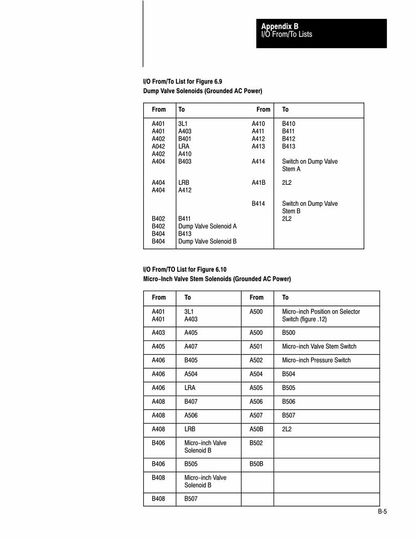
I/O From/To ListsAppendix B
B�5
I/O From/To List for Figure 6.9
Dump Valve Solenoids (Grounded AC Power)
From To From To
A401A401A402A042A402A404
3L1 A410A403 A411B401 A412LRA A413A410B403 A414
B410B411B412B413
Switch on Dump ValveStem A
A404A404
LRB A41BA412
2L2
B402B402B404B404
B414
B411Dump Valve Solenoid AB413Dump Valve Solenoid B
Switch on Dump ValveStem B2L2
I/O From/TO List for Figure 6.10
Micro-Inch Valve Stem Solenoids (Grounded AC Power)
From To From To
A401A401
3L1A403
A500 Micro-inch Position on SelectorSwitch (figure .12)
A403 A405 A500 B500
A405 A407 A501 Micro-inch Valve Stem Switch
A406 B405 A502 Micro-inch Pressure Switch
A406 A504 A504 B504
A406 LRA A505 B505
A408 B407 A506 B506
A408 A506 A507 B507
A408 LRB A50B 2L2
B406 Micro-inch ValveSolenoid B
B502
B406 B505 B50B
B408 Micro-inch ValveSolenoid B
B408 B507

I/I/O From/To ListsAppendix B
B�6
I/O From/To List for Figure 6.11
Cam Limit Switches
From To
A115 Brake Monitor Cam Limit Swich A
A116 Run-on Cam Limit Switch A
A117 Anti-repeat Cam Limit Switch A
A11B 2L2
B115 Brake Monitor Cam Limit Switch B
B116 Run-on Cam Limit Switch B
B117 Anti-repeat Cam Limit Switch B
B11B 2L2
I/O From/To List for Figure 6.12
Mode Select Switch, Main Motor Forward,
Barrier Guard, Stop-on-Top, and Arm Continuous
From To
A000 B000
A001 B001
A002 B002
A003 B003
A004 Main Motor Forward contactor
A004 B004
A005 Barrier Guard switch
A005 B005
A006 Stop-on-top switch in Station 4
A006 B006
A007 Arm Continuous switch in Station 1
A007 B007
A00B 2L2
B000 OFF position in Mode Select switch
B001 INCH position in Mode Select switch
B002 SINGLE position in Mode Select switch
B003 CONTINUOUS position in Mode Select switch
B00B 2L2

I/O From/To ListsAppendix B
B�7
I/O From/To List for Figure 6.13
Operator Station 1
From To
A010 Left RUN button (NC) contact)
A011 Right RUN button (NO) contact
A012 Left Active jumper connection
A016 Left INCH button (NC) contact
A017 Right INCH button (NO) contact
A01B 2L2
B010 Right RUN button (NC) contact
B011 Left RUN button (NO) contact
B012 Right Active jumper connection
B016 Right INCH button (NC) contact
B017 Left INCH button (NO) contact
B01B 2L2
I/O From/To List for Figure 6.14
Operator Station 2
From To
A013 Left RUN button (NC) contact)
A014 Right RUN button (NO) contact
A015 Left Active jumper conection
B013 Right RUN button (NC) contact
B014 Left RUN button (NO) contact
B015 Right Active jumper conection
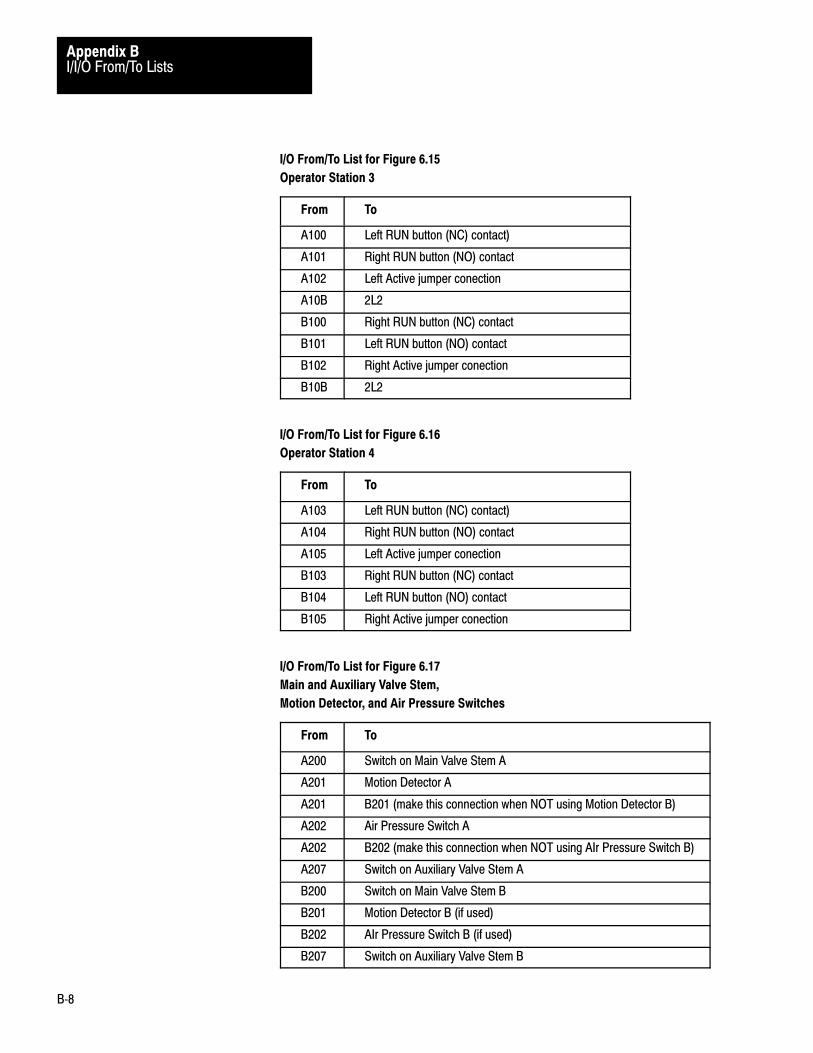
I/I/O From/To ListsAppendix B
B�8
I/O From/To List for Figure 6.15
Operator Station 3
From To
A100 Left RUN button (NC) contact)
A101 Right RUN button (NO) contact
A102 Left Active jumper conection
A10B 2L2
B100 Right RUN button (NC) contact
B101 Left RUN button (NO) contact
B102 Right Active jumper conection
B10B 2L2
I/O From/To List for Figure 6.16
Operator Station 4
From To
A103 Left RUN button (NC) contact)
A104 Right RUN button (NO) contact
A105 Left Active jumper conection
B103 Right RUN button (NC) contact
B104 Left RUN button (NO) contact
B105 Right Active jumper conection
I/O From/To List for Figure 6.17
Main and Auxiliary Valve Stem,
Motion Detector, and Air Pressure Switches
From To
A200 Switch on Main Valve Stem A
A201 Motion Detector A
A201 B201 (make this connection when NOT using Motion Detector B)
A202 Air Pressure Switch A
A202 B202 (make this connection when NOT using AIr Pressure Switch B)
A207 Switch on Auxiliary Valve Stem A
B200 Switch on Main Valve Stem B
B201 Motion Detector B (if used)
B202 AIr Pressure Switch B (if used)
B207 Switch on Auxiliary Valve Stem B
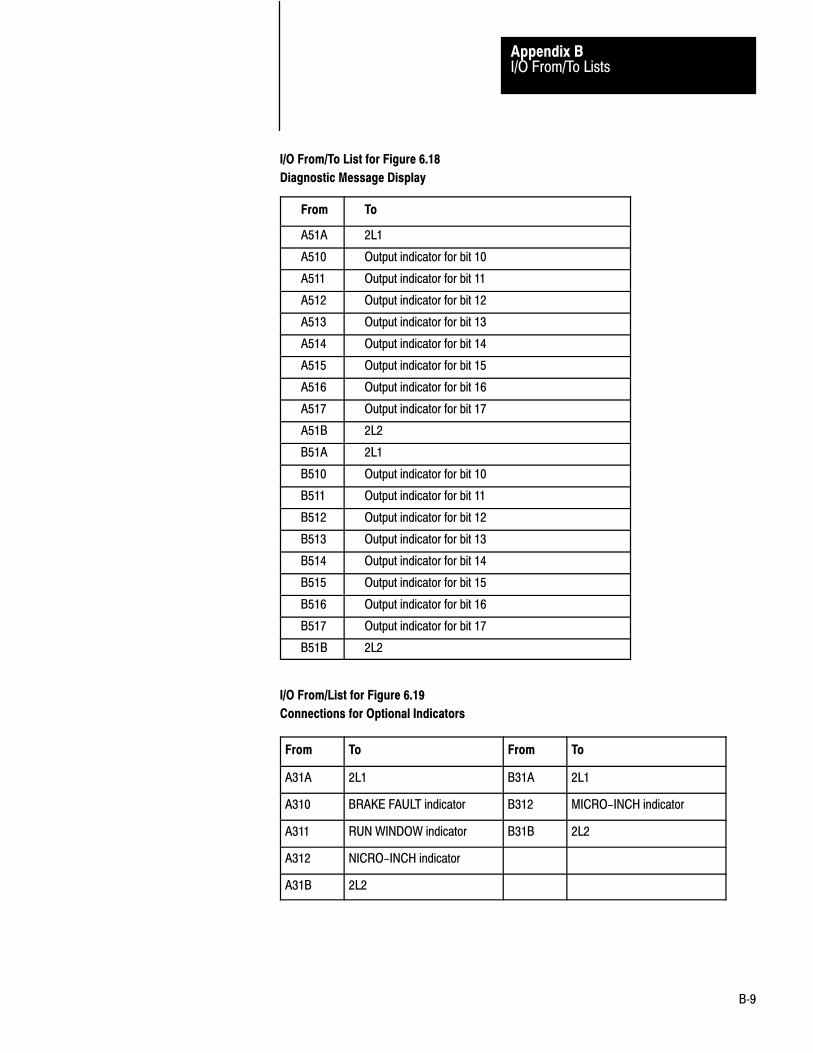
I/O From/To ListsAppendix B
B�9
I/O From/To List for Figure 6.18
Diagnostic Message Display
From To
A51A 2L1
A510 Output indicator for bit 10
A511 Output indicator for bit 11
A512 Output indicator for bit 12
A513 Output indicator for bit 13
A514 Output indicator for bit 14
A515 Output indicator for bit 15
A516 Output indicator for bit 16
A517 Output indicator for bit 17
A51B 2L2
B51A 2L1
B510 Output indicator for bit 10
B511 Output indicator for bit 11
B512 Output indicator for bit 12
B513 Output indicator for bit 13
B514 Output indicator for bit 14
B515 Output indicator for bit 15
B516 Output indicator for bit 16
B517 Output indicator for bit 17
B51B 2L2
I/O From/List for Figure 6.19
Connections for Optional Indicators
From To From To
A31A 2L1 B31A 2L1
A310 BRAKE FAULT indicator B312 MICRO-INCH indicator
A311 RUN WINDOW indicator B31B 2L2
A312 NICRO-INCH indicator
A31B 2L2

I/I/O From/To ListsAppendix B
B�10
I/O From/To List for Figure 6.20
Connections for PC Command Switches
From To
C213 Barrier Guard (NO) switch contact
C214 Reset Latched Messages (NO) switch
C215 Stop-on-top (NO) switch contact
C216 Lamp Test (NO) switch contact
C21B 2L2
NOTE: We have chosen rack 3, module group 2 for the address of this module in remote
I/O chassis C. Choose your own address based on your application requirements.

Symbols
**Empty**, 1�1PC, 1�2press, 1�2
A
addresses, bit monitor, A�1
B
bottom zone, 5�6
braking distance, 3�12
C
cable connections (twinaxial), 3�4
cam limit switches, 6�20anti-repeat, 5�3run-on, 5�3
chassis A and B, 3�1, 3�9
chassis C,, lamptest, 6�31
clutch/brake controllerdescription, 2�1, 3�1hardware, 3�3
command rungs, PC, 4�8
configurationSwitch settings, 3�8switch settings, 4�7
continuous mode, 5�9
control power, 6�3
crowbar,relays, 6�3test inputs, 6�4
D
diagnostic displaydownstroke, 5�6, 5�9flowcharts, 7�5message codes, 7�5
dummy plugs, 6�24
F
fault detection, solenoid valve, 6�8
functions, configurable, 3�7
H
hardware coniderations, 3�1
I
inch mode, 5�5
installation considerations, 6�1
interlock switches, 3�7
K
keying, 3�14
L
lamp test, 6�31
load resistors, 6�8
M
Manual, how to use, objectives, 1�1
message codes, 7�5
moduleplacement, 3�12switch settings, 3�10
module group 7, 3�12, 4�13
monitoring I/O, 4�13
multiple controllers, 3�6
N
noise immunity, 3�12
O
operator stations, 3�6, 6�24
P
panel switches, 3�6
press system, components, 2�1
programming, 4�1configuration rungs, 4�4fundamentals, 4�1PC command rungs, 4�9
Index

IndexI–2
R
rack address, 3�9
report generation, 4�14
response time, 3�12
rungs, 4�3
S
safetydocumentation, 2�3requirements, 6�1
seal relay, 6�3
single mode, 5�6
solenoid valvesauxiliary, 6�9dump, 6�9main, 6�8
suppression,, electrical noise, 6�11
switch, button,E-stop, 6�3Inch, 6�24Lamp Test, 6�31Run, 6�24
switch, input,, cam limit switches, 6�20
switchesinterlock, 3�7
panel, 3�6
system components, 2�1
T
terminator resistor, 3�4
Terminology, 1�2
top position, 2�1, 5�5
triac, sequential turn on, 3�11
troubleshootingconsiderations, 7�1example, 7�6procedure, 7�4
U
unique rack address, 3�11
upstroke, 5�6, 5�9
V
voting processor, 5�1
W
wire size, 6�2
Publication 1771-6.5.18 February 1992
Allen�Bradley, a Rockwell Automation Business, has been helping its customers improve pro�ductivity and quality for more than 90 years. We design, manufacture and support a broad rangeof automation products worldwide. They include logic processors, power and motion controldevices, operator interfaces, sensors and a variety of software. Rockwell is one of the worldsleading technology companies.
Worldwide representation.
Argentina • Australia • Austria • Bahrain • Belgium • Brazil • Bulgaria • Canada • Chile • China, PRC • Colombia • Costa Rica • Croatia • Cyprus • Czech Republic •Denmark • Ecuador • Egypt • El Salvador • Finland • France • Germany • Greece • Guatemala • Honduras • Hong Kong • Hungary • Iceland • India • Indonesia •
Ireland • Israel • Italy • Jamaica • Japan • Jordan • Korea • Kuwait • Lebanon • Malaysia • Mexico • Netherlands • New Zealand • Norway • Pakistan • Peru •Philippines • Poland • Portugal • Puerto Rico • Qatar • Romania • Russia�CIS • Saudi Arabia • Singapore • Slovakia • Slovenia • South Africa, Republic • Spain •Sweden • Switzerland • Taiwan • Thailand • Turkey • United Arab Emirates • United Kingdom • United States • Uruguay • Venezuela • Yugoslavia
Allen�Bradley Headquarters, 1201 South Second Street, Milwaukee, WI 53204 USA, Tel: (1) 414 382�2000 Fax: (1) 414 382�4444
Publication 1771-6.5.18 February 1992
Supersedes 1771-6.5.18 August 1986
PN 955111-35Copyright 1992 Allen�Bradley Company, Inc. Printed in USA