Modeling of Active Crowbar Protection Scheme for Various...
5
International Journal of Innovative Studies in Sciences and Engineering Technology (IJISSET) ISSN 2455-4863 (Online) www.ijisset.org Volume: 3 Issue: 5 | May 2017 © 2017, IJISSET Page 43 Modeling of Active Crowbar Protection Scheme for Various Types of Fault in Wind Energy Conversion System using DFIG R. Saravanakumar 1 , Dr. S. Kalyani 2 1 PG Student, Power System Engineering, Kamaraj College of Engineering and Technology, TamilNadu, INDIA 2 HOD/Professor, EEE Department, Kamaraj College of Engineering and Technology, TamilNadu, INDIA Abstract: Wind energy is one of the fastest growing non-conventional energy sources. Doubly Fed Induction Generator is often used nowadays in wind turbine. It is very sensitive to the grid disturbances, faults, and can harm the power electronic devices due to over voltages and over currents. Therefore, protection elements like Crowbar, Series Dynamic Breaking Resistor, DC Chopper are used to disconnect the machine during unhealthy conditions. In this paper, the crowbar protection method is used to ride through these disturbances. Low Voltage Ride Through (LVRT) is an important aspect for wind turbine systems to fulfil grid code requirements. In case of wind turbine technologies using doubly fed induction generators (DFIG), the reaction to grid voltage disturbances is sensitive. Since the stator of a DFIG is directly connected to a grid, this sort of machine is very sensitive to grid disturbances. Grid faults cause voltage sag and over-currents and over-voltages in rotor windings, which can damage the rotor-side converter (RSC). In order to protect the RSC, a classical solution as suggested in this paper is the installation of the Active Crowbar Protection Scheme Simulations have been carried out in MATLAB SIMULINK and the results demonstrate the effectiveness of the proposed strategy. Keywords: Doubly Fed Induction Generator (DFIG), Active Crowbar Protection (ACP), Rotor Side Converter (RSC), Grid Side Converter (GSC), Low Voltage Ride- Through(LVRT), Fault Ride Through (FRT) Wind Energy Conversion System (WECS). 1. INTRODUCTION The increased amount of power from decentralized, renewable energy systems, as especially wind energy systems, requires strong grid code requirements to maintain a stable and safe operation of the energy network. The grid codes cover rules considering the fault ride through behavior as well as the steady state active power and reactive power production. The actual grid codes stipulate that wind farms should contribute to power system control like frequency and voltage control to behave much as conventional power stations. A detailed review of grid code technical requirements regarding the connection of wind farms to the electrical power system is given in [1]. For operation during grid voltage faults it must be ensured that becomes clear that wind turbines must stay connected to the grid and should support the grid by generating reactive power to support and restore quickly the grid voltage after the fault. Among the various wind turbines, the doubly fed induction generator (DFIG) shown in Fig. 1 are widely preferred due to their variable speed operation, the separately controllable active and reactive power and their partially rated power converter. But, the reaction of DFIGs to grid voltage disturbances is sensitive [2], for symmetrical and unsymmetrical voltage dips, and requires additional protection for the rotor side power electronic converter. Fig1: Schematic diagram of DFIG wind turbine system However, because the stator of a DFIG is directly connected to the electrical grid, it is extremely sensitive to grid voltage disturbances. Voltage dips at the stator due to grid faults induce Over-voltage in the rotor windings, resulting in over currents of the rotor circuit, which may cause severe damage to the vulnerable rotor-side power electronic converter and large fluctuation of the dc-link voltage. Such a large rotor inrush current, dc-link overvoltage, and torque oscillations caused by grid faults are quite harmful for the DFIG-based wind turbines [2] and can lead to the destruction of converter and mechanical parts. Traditionally, once over-currents occur in rotor windings, the so-called crowbar is used to protect the rotor converter by short circuiting the rotor windings.
Transcript of Modeling of Active Crowbar Protection Scheme for Various...

International Journal of Innovative Studies in Sciences and Engineering Technology
(IJISSET)
ISSN 2455-4863 (Online) www.ijisset.org Volume: 3 Issue: 5 | May 2017
© 2017, IJISSET Page 43
Modeling of Active Crowbar Protection Scheme for Various Types
of Fault in Wind Energy Conversion System using DFIG
R. Saravanakumar1, Dr. S. Kalyani2
1PG Student, Power System Engineering, Kamaraj College of Engineering and Technology, TamilNadu, INDIA 2HOD/Professor, EEE Department, Kamaraj College of Engineering and Technology, TamilNadu, INDIA
Abstract: Wind energy is one of the fastest growing
non-conventional energy sources. Doubly Fed Induction
Generator is often used nowadays in wind turbine. It is
very sensitive to the grid disturbances, faults, and can
harm the power electronic devices due to over voltages
and over currents. Therefore, protection elements like
Crowbar, Series Dynamic Breaking Resistor, DC Chopper
are used to disconnect the machine during unhealthy
conditions. In this paper, the crowbar protection method
is used to ride through these disturbances. Low Voltage
Ride Through (LVRT) is an important aspect for wind
turbine systems to fulfil grid code requirements. In case
of wind turbine technologies using doubly fed induction
generators (DFIG), the reaction to grid voltage
disturbances is sensitive. Since the stator of a DFIG is
directly connected to a grid, this sort of machine is very
sensitive to grid disturbances. Grid faults cause voltage
sag and over-currents and over-voltages in rotor
windings, which can damage the rotor-side converter
(RSC). In order to protect the RSC, a classical solution as
suggested in this paper is the installation of the Active
Crowbar Protection Scheme Simulations have been
carried out in MATLAB SIMULINK and the results
demonstrate the effectiveness of the proposed strategy.
Keywords: Doubly Fed Induction Generator (DFIG),
Active Crowbar Protection (ACP), Rotor Side Converter
(RSC), Grid Side Converter (GSC), Low Voltage Ride-
Through(LVRT), Fault Ride Through (FRT) Wind Energy
Conversion System (WECS).
1. INTRODUCTION
The increased amount of power from decentralized,
renewable energy systems, as especially wind energy
systems, requires strong grid code requirements to
maintain a stable and safe operation of the energy
network. The grid codes cover rules considering the
fault ride through behavior as well as the steady state
active power and reactive power production. The
actual grid codes stipulate that wind farms should
contribute to power system control like frequency and
voltage control to behave much as conventional power
stations. A detailed review of grid code technical
requirements regarding the connection of wind farms
to the electrical power system is given in [1]. For
operation during grid voltage faults it must be ensured
that becomes clear that wind turbines must stay
connected to the grid and should support the grid by
generating reactive power to support and restore
quickly the grid voltage after the fault.
Among the various wind turbines, the doubly fed
induction generator (DFIG) shown in Fig. 1 are widely
preferred due to their variable speed operation, the
separately controllable active and reactive power and
their partially rated power converter. But, the reaction
of DFIGs to grid voltage disturbances is sensitive [2],
for symmetrical and unsymmetrical voltage dips, and
requires additional protection for the rotor side power
electronic converter.
Fig1: Schematic diagram of DFIG wind turbine system
However, because the stator of a DFIG is directly
connected to the electrical grid, it is extremely sensitive
to grid voltage disturbances. Voltage dips at the stator
due to grid faults induce Over-voltage in the rotor
windings, resulting in over currents of the rotor circuit,
which may cause severe damage to the vulnerable
rotor-side power electronic converter and large
fluctuation of the dc-link voltage. Such a large rotor
inrush current, dc-link overvoltage, and torque
oscillations caused by grid faults are quite harmful for
the DFIG-based wind turbines [2] and can lead to the
destruction of converter and mechanical parts.
Traditionally, once over-currents occur in rotor
windings, the so-called crowbar is used to protect the
rotor converter by short circuiting the rotor windings.

International Journal of Innovative Studies in Sciences and Engineering Technology
(IJISSET)
ISSN 2455-4863 (Online) www.ijisset.org Volume: 3 Issue: 5 | May 2017
© 2017, IJISSET Page 44
Fig. 1 shows the block diagram of a DFIG equipped with
a crowbar [6]. As can be seen, the active crowbar
consists of resistors in series and capacitor, which are
controlled by power electronic devices.
2. DOUBLY FED INDUCTION GENERATOR
Variable speed turbines are more popular than fixed
wind speed turbine, due to its ability to capture more
energy from wind, improved power quality and
reduced mechanical stress on the wind turbine. DFIG
can run at variable speed but produce a voltage at the
frequency of the grid. In contrast to a conventional
simple induction generator the electrical power
generated by a DFIG is independent of the speed.
Therefore, it is possible to realize a variable speed
operation which requires adjusting the mechanical
speed of the rotor to the wind speed so that the wind
turbine operates at the aerodynamically optimal point
over a certain wind speed range. DFIG has various
advantages like its low converter rating consequently
its relatively high efficiency, lighter in weight, its low
cost and its capability of decoupling the control of both
active and reactive power. Therefore, the DFIG has its
distinguished place among many variable speed wind
turbine generators.
Fig2: DFIG Scheme
3. DFIG PROTECTION TECHNIQUES
There are so many protection techniques like DC
Chopper, Dynamic braking register, crowbar for DFIG
but the present work focused on Active Crowbar
Protection technique which is explained in the detailed.
3.1 CROWBAR TECHNIQUE
The conventional crowbar (CB) protection circuit is a
specially designed electrical circuit.. The Crowbar
circuit provides a low resistance path or a short circuit
across the output voltage. Generally, resistors,
thyristor, TRIAC, IGBT’s are used as the shorting device.
The triggering of these devices depend on the current
limiting circuitry of the power supply unit.
The Crowbar circuits can be classified as active
crowbar circuits and passive crowbar circuits.An active
crowbar provides the short circuit during the transient
(high-voltage) conditions and it again allows the device
to resume normal operations when the transient is
over. Transistor, IGBTs, gate turn off thyristor or forced
commutated thyristor are generally used in active
crowbars for switching purposes. Active crowbar is
used to protect the RSC of the DFIG from high voltage
and the current transients produced by the voltage sags
during grid faults. Hence, the DFIG can ride through the
fault and can continue the power supply even during
the grid voltage sags.
Fig 3: Active Crowbar for DFIG rotor
Conventional crowbar circuit, previously used in DFIG
systems is consisting of resistors and power electronic
switches. Due to the presence of resistors, it can
restrict the high short-circuit current up to a certain
extent but it cannot restrict DFIG from absorption of
reactive power from the grid during the fault which
further adds instability to the system performance
along with power quality of the system. In order to
overcome such issues and to improvise the FRT
capability, a new design scheme of an active crowbar
circuit is proposed which shows better performance in
limiting the rotor current as well as improving the
active and reactive power profile of the DFIG compared
to traditional crowbar circuits. In this
ACB protection circuit, a capacitor in series with the
resistor, an IGBT switch and a diode based rectifier
circuit is connected together as shown in Fig 4. This
scheme is Named as Novel Active Crowbar Protection
(NACB_P) circuit. The capacitor is selected to
compensate reactive power during fault and to
accommodate the ripples generated in the dc link. It
forces the current through the DC-link to be balanced
and hence tries to keep the DC-link voltage maintained
during fault.
3.2 MODELLING OF ACTIVE CROWBAR
When the crowbar is in ON condition the RSC pulses
are totally disabled and the machine will behave like a
Squirrel Cage Induction Machine (SCIM) directly
coupled to the grid side. The magnetization of the
machine which was provided by the Rotor Side
International Journal of Innovative Studies in Sciences and Engineering Technology
(IJISSET)
ISSN 2455-4863 (Online) www.ijisset.org Volume: 3 Issue: 5 | May 2017
© 2017, IJISSET Page 45
Converter during the normal operation is lost and the
machine will draw large amount of reactive power
from grid, which is called “grid codes”. Though,
triggering of crowbar circuit produces high stress to
the mechanical component of the system. This scheme
(crowbar protection) is reliable just because of its low
cost and simple construction. Simulation diagram of
DFIG with crowbar protection is shown in Fig 4
developed using MATLAB/Simulink.
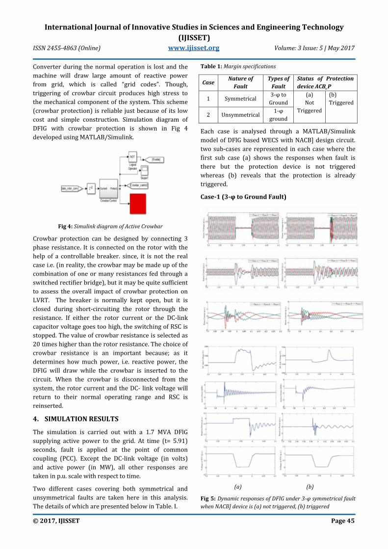
Fig 4: Simulink diagram of Active Crowbar
Crowbar protection can be designed by connecting 3
phase resistance. It is connected on the rotor with the
help of a controllable breaker. since, it is not the real
case i.e. (in reality, the crowbar may be made up of the
combination of one or many resistances fed through a
switched rectifier bridge), but it may be quite sufficient
to assess the overall impact of crowbar protection on
LVRT. The breaker is normally kept open, but it is
closed during short-circuiting the rotor through the
resistance. If either the rotor current or the DC-link
capacitor voltage goes too high, the switching of RSC is
stopped. The value of crowbar resistance is selected as
20 times higher than the rotor resistance. The choice of
crowbar resistance is an important because; as it
determines how much power, i.e. reactive power, the
DFIG will draw while the crowbar is inserted to the
circuit. When the crowbar is disconnected from the
system, the rotor current and the DC- link voltage will
return to their normal operating range and RSC is
reinserted.
4. SIMULATION RESULTS
The simulation is carried out with a 1.7 MVA DFlG
supplying active power to the grid. At time (t= 5.91)
seconds, fault is applied at the point of common
coupling (PCC). Except the DC-link voltage (in volts)
and active power (in MW), all other responses are
taken in p.u. scale with respect to time.
Two different cases covering both symmetrical and
unsymmetrical faults are taken here in this analysis.
The details of which are presented below in Table. I.
Table 1: Margin specifications
Case Nature of
Fault
Types of
Fault
Status of Protection
device ACB_P
1 Symmetrical 3-φ to
Ground
(a)
Not
Triggered
(b)
Triggered
2 Unsymmetrical 1-φ
ground
Each case is analysed through a MATLAB/Simulink
model of DFlG based WECS with NACB] design circuit.
two sub-cases are represented in each case where the
first sub case (a) shows the responses when fault is
there but the protection device is not triggered
whereas (b) reveals that the protection is already
triggered.
Case-1 (3-φ to Ground Fault)
(a) (b)
Fig 5: Dynamic responses of DFIG under 3-φ symmetrical fault
when NACB] device is (a) not triggered, (b) triggered

International Journal of Innovative Studies in Sciences and Engineering Technology
(IJISSET)
ISSN 2455-4863 (Online) www.ijisset.org Volume: 3 Issue: 5 | May 2017
© 2017, IJISSET Page 46
Case-II (l-φ to Ground Fault)
(a) (b)
Fig 6: Dynamic responses of DFIG under 1-φ un symmetrical
fault when NACB] device is (a) not triggered, (b) triggered
The simulation results for the FRT performance of DFIG
system with a three-phase symmetrical fault are shown
in Fig. 5. The DFIG was intended to run at Ip.u. and its
nominal load. The symmetrical fault occurs at t=5.91s,
lasting for 0.7s. It is seen from Fig. 5 (a) that at the very
moment when fault occurs and the protection circuit
NACB _P is not triggered, the stator voltage nearly
reduces to zero and the surge current in the stator
winding gradually reduces below the rated value of 1
p.u that is to zero. All the three phases of the rotor
current surges to 2p.u. which is hazardous for the
partially rated RSC to withstand.
In Fig.5 (b), it is shown that the Novel Crowbar is
triggered at t=5.91s as soon as the symmetrical fault
occurred. Hence the voltage and current profile of the
stator and that of rotor current improves significantly,
ensuring enhanced FRT capability of the DFIG. Most
importantly, the C-phase current of the stator which
was zero in Fig.5(a), now stabilises to its rated value as
seen in Fig. 5(b) soon after NACB_P is triggered.
Similarly the other two phases, A and B of the stator
current regains its balanced state very quickly.
The rotor current profile of the DFIG improves
significantly reducing the surge value nearer to its
nominal value after the application of proposed
protection because the capacitor implemented in the
protection design accommodates the ripples generated
in the current due to the fault. It is observed from Fig.
5(a) that during fault, the DC-link voltage increases
from steady state value 1150V to around 1600V which
must be avoided to protect the DC-link capacitor as
well as the GSc. But, as shown in Fig. 5(b), the DC-link
voltage varies within the safe range from 11OOV to
1300V after the protection is triggered. The active
power of the system suddenly becomes zero from rated
value of 1.5 MW and the reactive value fluctuates
around zero making the whole system unstable, the
terminal voltage at PCC reduces to zero as seen from
Fig. 5(a). But, as the protection circuit is triggered in
Fig. 5(b), the capacitor used in the protection
compensates reactive power making it nearly zero.
Active power and terminal voltage characteristics of
DFIG are also observed to be improved due to the
control action of the novel protection circuit.
In Fig. 6 (a) and (b), the simulation responses of DFIG
during an unsymmetrical I-φ to ground fault is
observed without and with the proposed protection
scheme respectively. In Fig.6(a), all the dynamic
responses of the DFIG along with the instantaneous
stator voltage and current profiles are presented which
are affected due the fault in a similar manner as
explained in case of symmetrical fault. But the
difference lies in the number of phases of current and
voltage affected. After the NACB _P is triggered, nearly
steady-state values for stator current, rotor current and
DClink voltages are observed in Fig. 7(b). The reason
how it works is explained in previous section, that the
capacitor Cb in proposed scheme is calibrated in such a
way that it nullifies a major part of the transients
generated in the rotor current and hence in the DC-link
voltage.
5. CONCLUSIONS
In this paper, a protection design is described which
has the objective to maintain the connection of the
DFIG to the grid in case of grid faults so that it can
continue the power supply after the clearance of the
faults. The key objective of the protection design is to
restrict the high current within safe limits and to
International Journal of Innovative Studies in Sciences and Engineering Technology
(IJISSET)
ISSN 2455-4863 (Online) www.ijisset.org Volume: 3 Issue: 5 | May 2017
© 2017, IJISSET Page 47
facilitate a bypass for it in the rotor side of the
generator through the set of resistor and capacitor
connected in series. Compared to conventional
crowbar, NACB_P is more effective in improving the
Fault Ride through capability of DFIG. The proposed
design is described and applied through a time
dependent analytical expression of the transient stator
and rotor currents of the DFIG. Simulation results
reveal the effectiveness of the proposed novel crowbar
applicable both in case of symmetrical and
unsymmetrical grid faults.
REFERENCES
[1] S. Chaudhary, S.P Chaudhary and P. Crossely,
“Micro grid and Active Distribution Networks”,
IET Renewable Energy Series 6, 2009
[2] Sheng Hu, Xinchun Lin, Yong Kang, and Xudong
Zou, “An Improved Low-Voltage Ride-Through
Control Strategy of Doubly Fed Induction
Generator During Grid Faults”, IEEE transactions
on power electronics, vol. 26, no. 12, December
2011, pp 3653-3665.
[3] Erlich, H. Wrede, and C. Feltes, Dynamic Behavior
of DFIG-Based Wind Turbines during Grid Faults,
14244-0844-X/07, 2007 IEEE, pp 1195-1200.
[4] F. Katiraei, M. R. Iravani, P. W. Lehn, “Micro-Grid
Autonomous Operation During and Subsequent to
Islanding Process”, IEEE transactions on power
delivery, vol. 20, no. 1, Paper no. TPWRD- 00103-
2003, pp.248-256, January 2005
[5] F. D. Kanellos, A. I. Tsouchnikas, N. D.
Hatziargyriou, Micro-Grid Simulation during Grid-
Connected and Islanded Modes of Operation,
presented at the International Conference on
Power Systems Transients (IPST‟05) in Montreal
Canada, June 19-23, 2005 Paper No. IPST05 – 113
[6] Jes´us L´opez, Pablo Sanchis, Xavier Roboam, &
Luis Marroyo, “Dynamic Behavior of the Doubly
Fed Induction Generator During Three Phase
Voltage Dips” IEEE transactions on energy
conversion, vol. 22, no. 3, pp 709-717, September
2007
[7] Omar Badrana, Emad Abdulhadi, Rustum
Mamlook, “Evaluation of parameters affecting
wind turbine power generation”.
[8] Dr. Gary L. Johnson “Wind Energy Systems”
November 21, 2001, vol I.
[9] K. L. Shi, T. F. Chan, Y. K. Wong and S. L. Ho,
Modeling and Simulation of Direct Self-Control
Systems, Vol. 19, No. 4, pp. 646-654, 2003, 0949-
149, Tempus Publications
AUTHORS' BIOGRAPHY
R. Saravanakumar received his
bachelor’s degree in electrical and
electronic engineering from Kamaraj
College ofEngineering and Technology,
Virudhunagar, in the year of 2015. He is
currently doing her master’s degree in
Kamaraj College of Engineering and
Technology, Virudhunagar. His research
interest in wind energy conversion
system and DFIG using converters.
S. Kalyani is currently working as
Professor and Head in the department of
Electrical & Electronics Engineering at
Kamaraj college of Engineering &
Technology, Virudhunagar. She obtained
her PhD degree from Indian Institute of
Technology of Madras. Chennai in 2011