16.317 Microprocessor Systems Design I Instructor: Dr. Michael Geiger Spring 2014 Lecture 32: PIC...
16
16.317 Microprocessor Systems Design I Instructor: Dr. Michael Geiger Spring 2014 Lecture 32: PIC example programs: Analog to digital conversion
-
Upload
june-craig -
Category
Documents
-
view
216 -
download
0
Transcript of 16.317 Microprocessor Systems Design I Instructor: Dr. Michael Geiger Spring 2014 Lecture 32: PIC...

16.317Microprocessor Systems
Design IInstructor: Dr. Michael Geiger
Spring 2014
Lecture 32:PIC example programs:
Analog to digital conversion

Lecture outline Announcements/reminders
HW 6 due Friday, 5/2 Group assignment with PICkits—groups of 2 or 3
HW 7 to be posted; also due Friday, 5/2 Extra-credit problem set Can replace lowest grade for HW 1-5 only
Everyone must complete HW 6 Exam 3: Tuesday, 5/6, 11:30-2:30
Must complete course evaluation—will post on website
Review: PIC interrupts Today’s lecture
Analog-to-digital conversion
04/18/23 Microprocessors I: Lecture 32 2

Review: Interrupts PIC controllers allow internal and external interrupts Single interrupt service routine
Must determine interrupt cause, then handle Code addresses handled slightly differently
Processor goes to address 0 on reset, 4 on interrupt Reset “vector”: jump to start of main program Interrupt “vector”: jump to start of ISR
Interrupt setup Enable device-specific interrupts first Enable global interrupts (GIE bit on PIC16F1829)
Interrupt handling Determine which device caused interrupt Clear device-specific interrupt flag Execute code to actually process interrupt, then retfie
04/18/23 Microprocessors I: Lecture 32 3
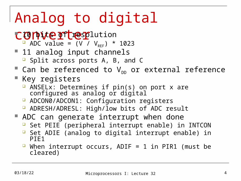
Analog to digital converter 10 bits of resolution
ADC value = (V / VREF) * 1023 11 analog input channels
Split across ports A, B, and C Can be referenced to VDD or external reference Key registers
ANSELx: Determines if pin(s) on port x are configured as analog or digital
ADCON0/ADCON1: Configuration registers ADRESH/ADRESL: High/low bits of ADC result
ADC can generate interrupt when done Set PEIE (peripheral interrupt enable) in INTCON Set ADIE (analog to digital interrupt enable) in PIE1 When interrupt occurs, ADIF = 1 in PIR1 (must be cleared)
04/18/23 Microprocessors I: Lecture 32 4
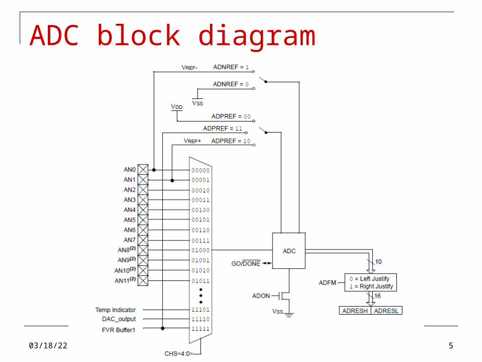
ADC block diagram
04/18/23 Microprocessors I: Lecture 32 5

ADCON0
CHS <4:0>: channel select GO/DONE’: start/end conversion
Explicitly set to 1 to start conversion ADC will clear when conversion is done
ADON: Turns ADC on/off
04/18/23 Microprocessors I: Lecture 32 6
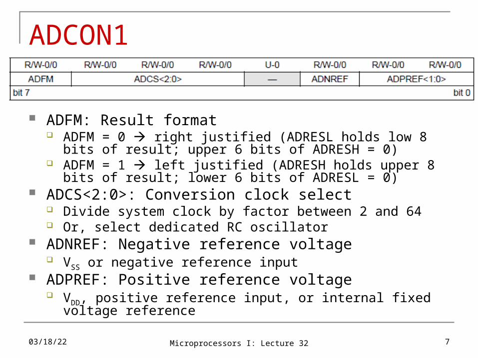
ADCON1
ADFM: Result format ADFM = 0 right justified (ADRESL holds low 8 bits of result;
upper 6 bits of ADRESH = 0) ADFM = 1 left justified (ADRESH holds upper 8 bits of result;
lower 6 bits of ADRESL = 0) ADCS<2:0>: Conversion clock select
Divide system clock by factor between 2 and 64 Or, select dedicated RC oscillator
ADNREF: Negative reference voltage VSS or negative reference input
ADPREF: Positive reference voltage VDD, positive reference input, or internal fixed voltage reference
04/18/23 Microprocessors I: Lecture 32 7

ADC setup In assembly (a2d.asm)
;already in bank1bsf TRISA, 4 ;Pot.connected to RA4 movlw b'00001101‘ ;select RA4 as ADC source movwf ADCON0 ; & enable (actually AN3)movlw b'00010000‘ ;left justified, Fosc/8 movwf ADCON1 ; speed, vref is Vddbanksel ANSELA ;bank3bsf ANSELA, 4 ;analog for ADC
In C (a2d.c)TRISAbits.TRISA4 = 1; //Pot. connected to RA4ANSELAbits.ANSA4 = 1; //analogADCON0 = 0b00001101; //select RA4 as source of ADC
// and enable module (AN3)ADCON1 = 0b00010000; //left justified, FOSC/8
// ref is Vdd
04/18/23 Microprocessors I: Lecture 32 8

ADC access in assembly (a2d.asm) Read ADC; put upper 4 bits on LEDs;Start the ADC nop ;required ADC delay banksel ADCON0 bsf ADCON0, GO ;start the ADC btfsc ADCON0, GO ;this bit will be cleared
when ; the conversion is complete
goto $-1 ;keep checking until GO clear
;Grab Results and write to the LEDs swapf ADRESH, w ;Get top 4 MSbs banksel LATC movwf LATC ;move into the LEDs
04/18/23 Microprocessors I: Lecture 32 9

ADC access in C (a2d.c)while (1) {
__delay_us(5); //wait for ADC // charging cap to // settle
GO = 1;//wait for conversion to finishwhile (GO) continue;
//grab the top 4 MSbsLATC = (ADRESH >> 4);
}
04/18/23 Microprocessors I: Lecture 32 10
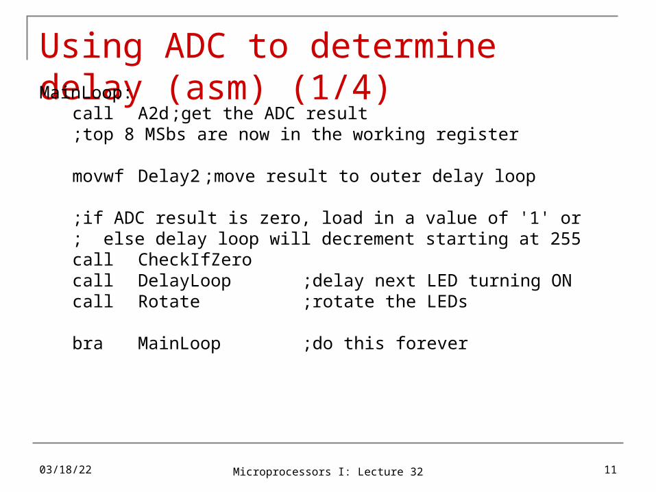
Using ADC to determine delay (asm) (1/4)MainLoop:
call A2d;get the ADC result;top 8 MSbs are now in the working register
movwf Delay2 ;move result to outer delay loop
;if ADC result is zero, load in a value of '1' or ; else delay loop will decrement starting at 255call CheckIfZerocall DelayLoop ;delay next LED turning ONcall Rotate ;rotate the LEDs
bra MainLoop ;do this forever
04/18/23 Microprocessors I: Lecture 32 11

Using ADC to determine delay (asm) (2/4)CheckIfZero:
movlw d'0‘ ;load wreg with '0'xorwf Delay2, w ;XOR wreg with the ADC
; result and save in wregbtfss STATUS, Z ;if ADC result is NOT '0',
; simply return to MainLoopreturn ;return to MainLoop
;ADC result IS '0'. Load delay routine with '1'; to avoid decrementing a rollover value of 255movlw d'1'movwf Delay2 ;move into delay locationreturn ;return to MainLoop
04/18/23 Microprocessors I: Lecture 32 12

Using ADC to determine delay (asm) (3/4)A2d:
;Start the ADCnop ;required ADC delaybanksel ADCON0bsf ADCON0, GO ;start the ADCbtfsc ADCON0, GO ;this bit cleared when
; conversion completegoto $-1 ; check until GO clearmovf ADRESH, w ;Get the top 8 MSbs
return
04/18/23 Microprocessors I: Lecture 32 13

Using ADC to determine delay (asm) (4/4)DelayLoop:
;Delay amount determined by ADCdecfsz Delay1,f ;will always be
; decrementing 255goto DelayLoopdecfsz Delay2,f ;Delay2 = 8 MSBs
; from ADC
goto DelayLoop
return04/18/23 Microprocessors I: Lecture 32 14

Using ADC to determine delay (C)while (1) {
delay = adc(); //grab the top 8 MSbs__delay_ms(5); //delay for AT LEAST 5ms
//decrement the 8 MSbs of the ADC and delay 2ms // for eachwhile (delay-- != 0)
__delay_ms(2);
//shift to the right to light up the next LEDLATC >> = 1;
//when the last LED is lit, restart the patternif(STATUSbits.C)
LATCbits.LATC3 = 1;}
04/18/23 Microprocessors I: Lecture 32 15

Final notes Next week
Office hours during class time on M/W Friday: Exam 3 Preview lecture
Reminders: HW 6 due Friday, 5/2
Group assignment with PICkits—groups of 2 or 3 HW 7 to be posted; also due Friday, 5/2
Extra-credit problem set Can replace lowest grade for HW 1-5 only
Everyone must complete HW 6 Exam 3: Tuesday, 5/6, 11:30-2:30
Must complete course evaluation—will post on website
04/18/23 Microprocessors I: Lecture 32 16