14-Wind Energy Conversion Systems
66
14-Wind Energy Conversion Systems ECEGR 4530 Renewable Energy Systems
Transcript of 14-Wind Energy Conversion Systems
14-Wind Energy Conversion Systems
ECEGR 4530
Renewable Energy Systems
Overview
• Wind Industry
• Wind Turbine Types
• Tip Speed Ratio
• Power Coefficient
• Wind Turbine Aerodynamics
• Wind Turbine Operation
2Dr. Louie
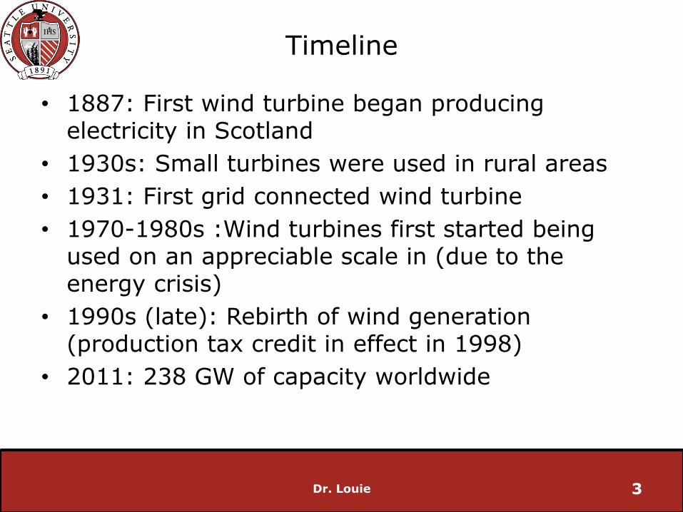
Timeline
• 1887: First wind turbine began producing electricity in Scotland
• 1930s: Small turbines were used in rural areas
• 1931: First grid connected wind turbine
• 1970-1980s :Wind turbines first started being used on an appreciable scale in (due to the energy crisis)
• 1990s (late): Rebirth of wind generation (production tax credit in effect in 1998)
• 2011: 238 GW of capacity worldwide
Dr. Louie 3
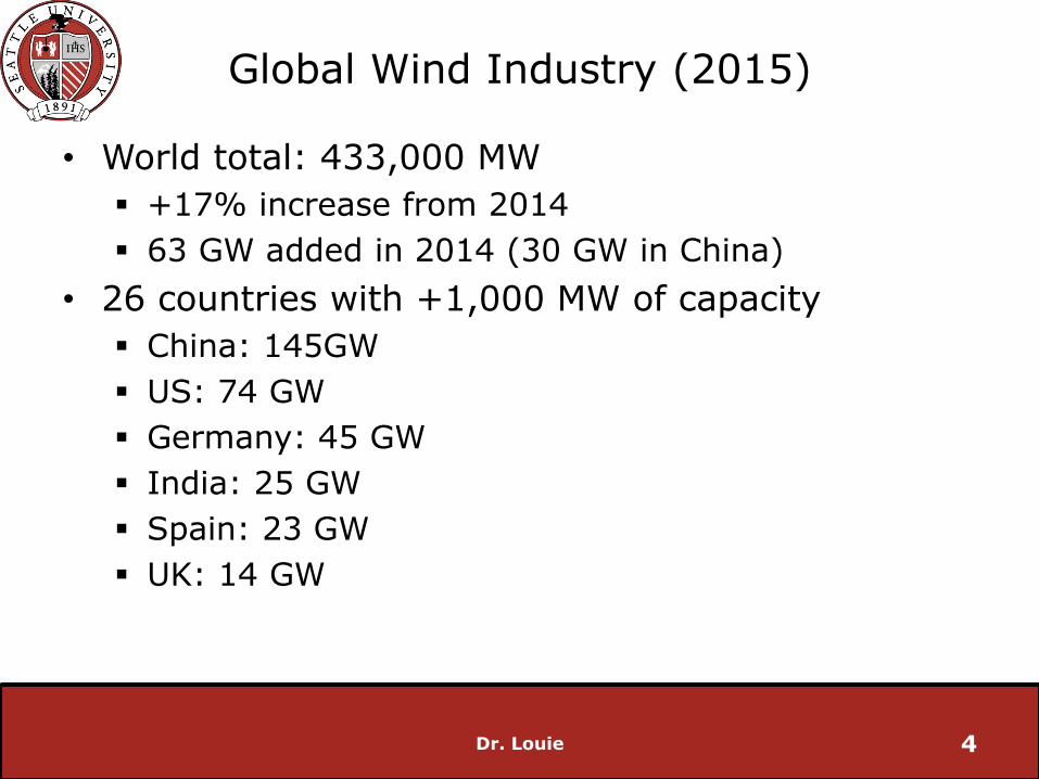
Global Wind Industry (2015)
• World total: 433,000 MW
+17% increase from 2014
63 GW added in 2014 (30 GW in China)
• 26 countries with +1,000 MW of capacity
China: 145GW
US: 74 GW
Germany: 45 GW
India: 25 GW
Spain: 23 GW
UK: 14 GW
Dr. Louie 4
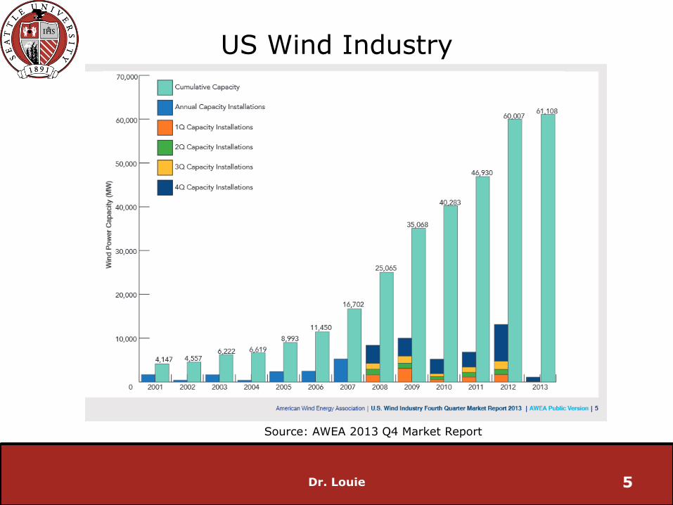
US Wind Industry
Dr. Louie 5
US Total Wind Power Capacities
Source: AWEA 2013 Q4 Market Report
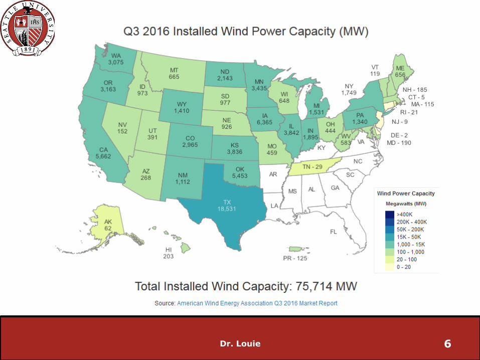
US Wind Industry
Dr. Louie 6
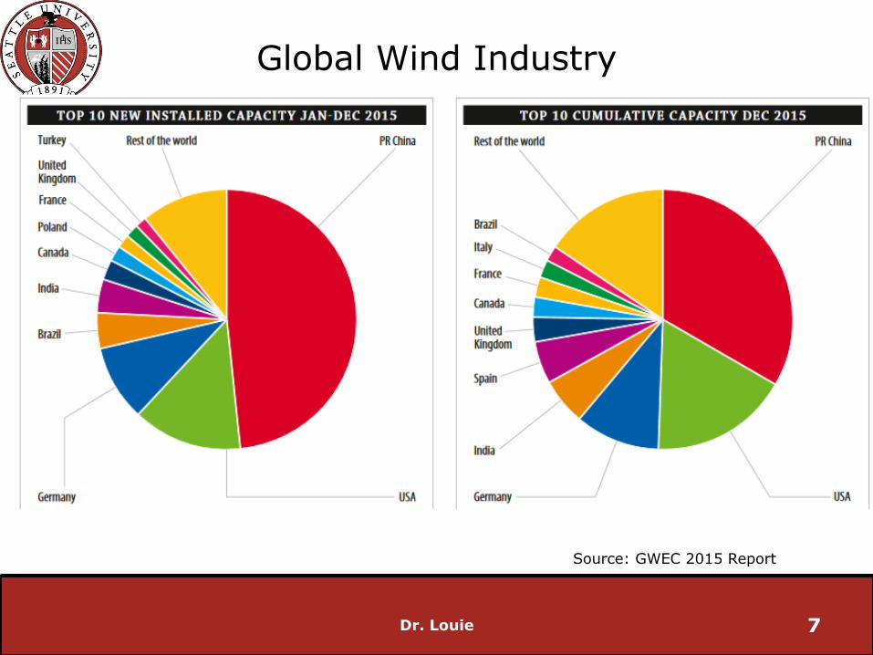
Global Wind Industry
Dr. Louie 7
Source: GWEC 2015 Report

Global Wind Industry
Dr. Louie 8
Source: GWEC 2015 Report

Global Wind Industry
Dr. Louie 9
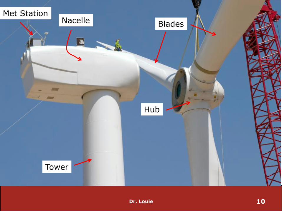
Dr. Louie 10
Tower
Nacelle
Hub
Blades
Met Station
Dr. Louie 11
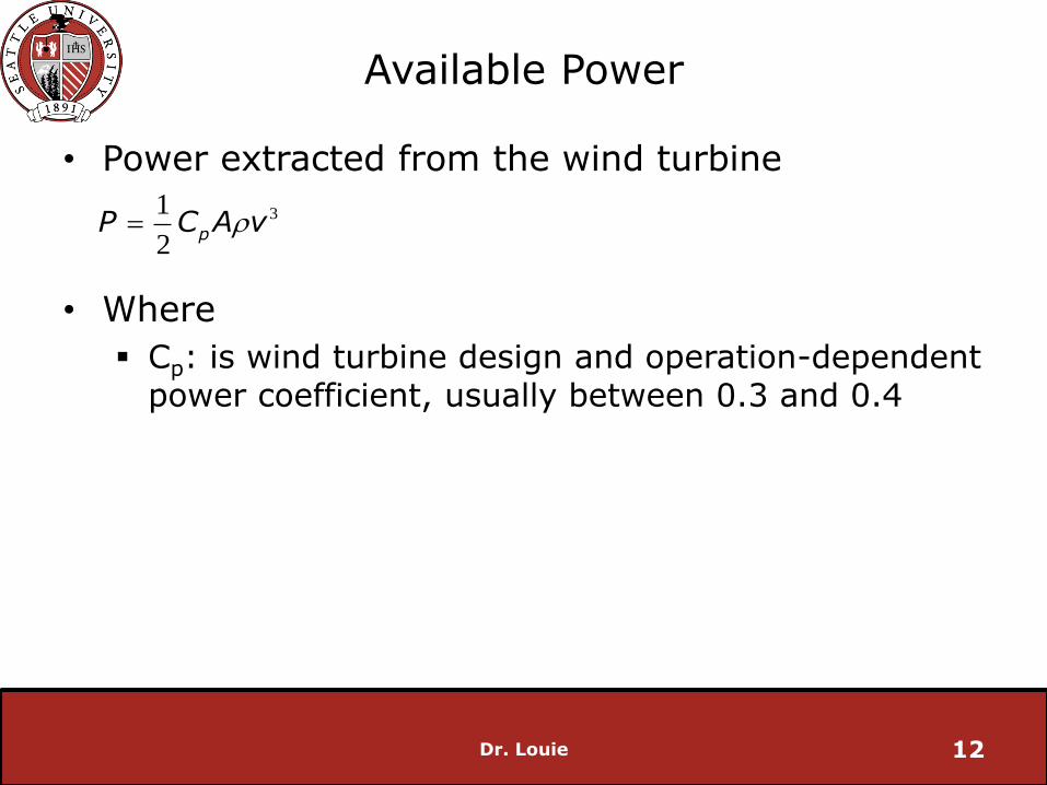
Available Power
• Power extracted from the wind turbine
• Where
Cp: is wind turbine design and operation-dependent power coefficient, usually between 0.3 and 0.4
Dr. Louie 12
31
2p
P C A v
Wind Turbine Types
• What wind types of wind turbines are there?
• Generally classified as
Vertical Axis Wind Turbines (VAWT)
Horizontal Axis Wind Turbines (HAWT)
Dr. Louie 13
Wind Turbine Types
• Vertical Axis Wind Turbines (VAWT) are less common but have niche applications
• Advantages:
do not have to face the wind to harness energy
generator is located at the base which has mechanical advantages
• VAWTs are more expensive
Dr. Louie 14
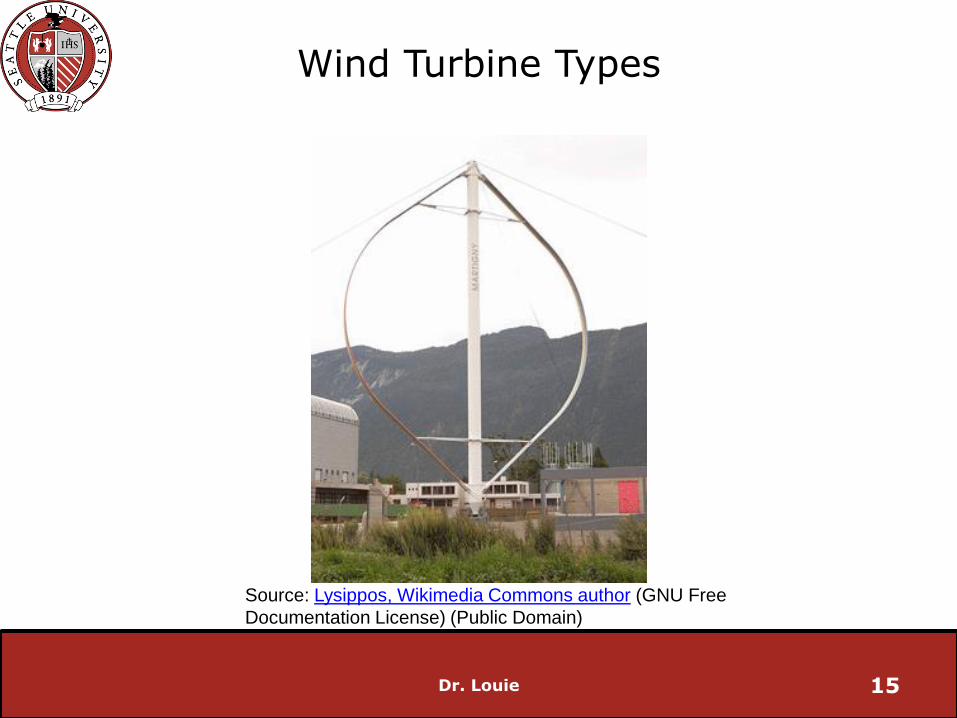
Wind Turbine Types
Dr. Louie 15
Source: Lysippos, Wikimedia Commons author (GNU Free
Documentation License) (Public Domain)

Wind Turbine Types
• Horizontal Axis Wind Turbines are the most common
• Usually 2 or 3 blades
Dr. Louie 16

Wind Turbine Types
Dr. Louie 17
Source: http://wind-energy-the-facts.org Source: https://energysavingwales.org.uk
single blade wind turbine two bladed wind turbine

Dr. Louie 18

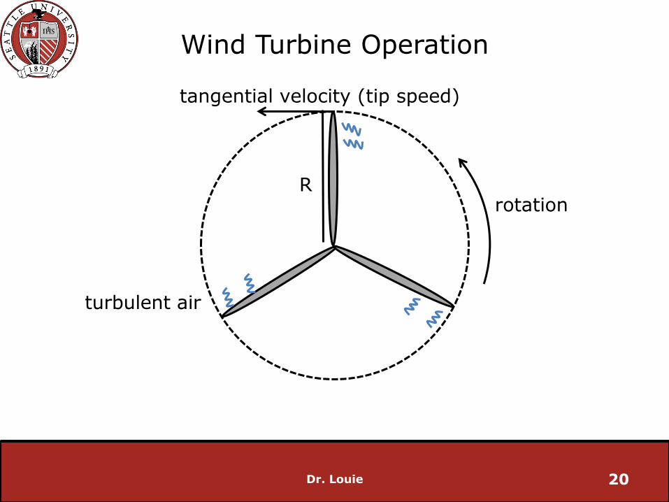
Wind Turbine Operation
• Wind turbines extract energy from the interaction of the rotor blades and the moving air
• Goal: have blades interact with as much air as possible without passing through turbulent wake left by another blade
Dr. Louie 19
Wind Turbine Operation
Dr. Louie 20
rotationR
turbulent air
tangential velocity (tip speed)
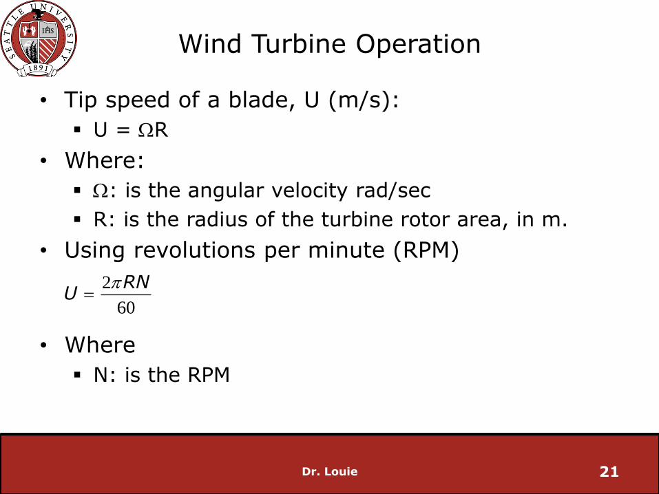
Wind Turbine Operation
• Tip speed of a blade, U (m/s):
U = WR
• Where:
W: is the angular velocity rad/sec
R: is the radius of the turbine rotor area, in m.
• Using revolutions per minute (RPM)
• Where
N: is the RPM
Dr. Louie 21
2
60
RNU

Wind Turbine Operation
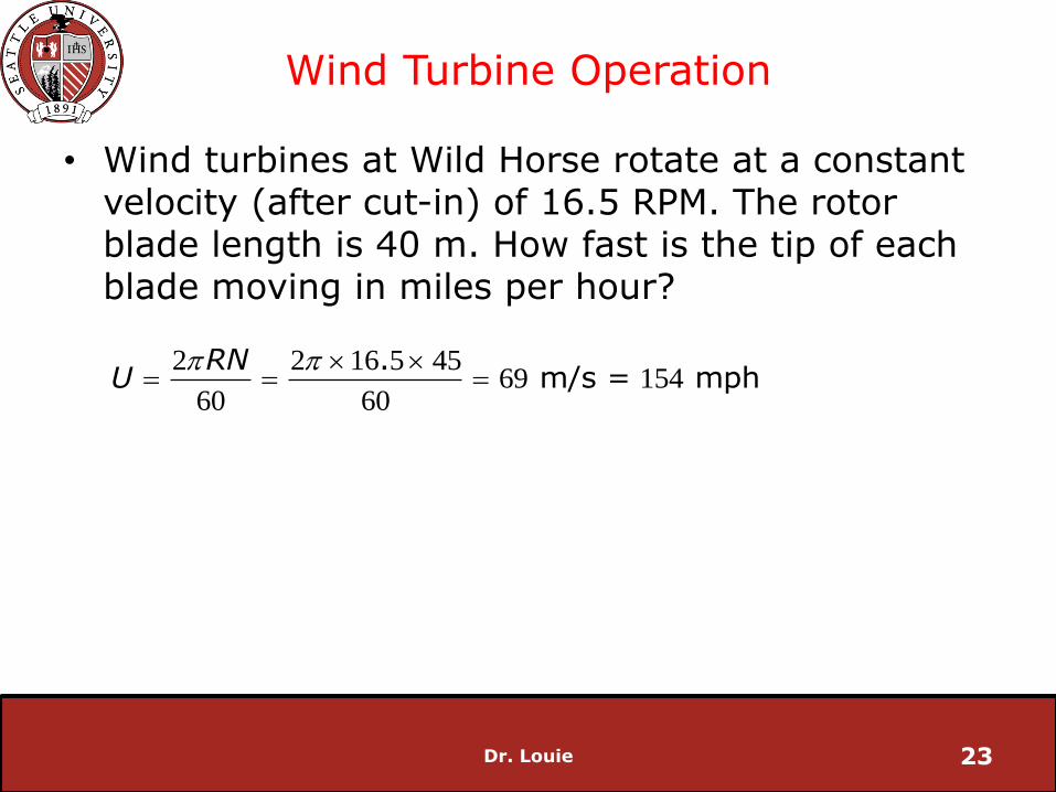
• Wind turbines at Wild Horse rotate at a constant velocity (after cut-in) of 16.5 RPM. The rotor blade length is 40 m. How fast is the tip of each blade moving in miles per hour?
Hint: there are 1609 m in 1 mile
Dr. Louie 22
Wind Turbine Operation
• Wind turbines at Wild Horse rotate at a constant velocity (after cut-in) of 16.5 RPM. The rotor blade length is 40 m. How fast is the tip of each blade moving in miles per hour?
Dr. Louie 23
2 2 16 5 4569 154
60 60
. m/s = mph
RNU
Wind Turbine Operation
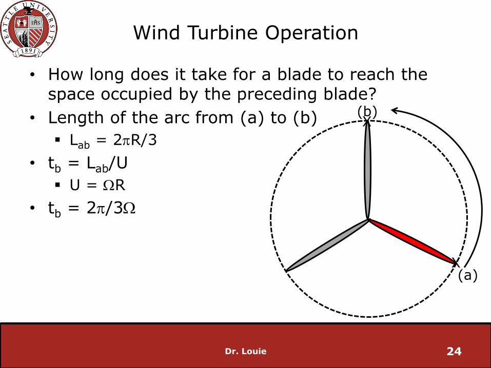
• How long does it take for a blade to reach the space occupied by the preceding blade?
• Length of the arc from (a) to (b)
Lab = 2R/3
• tb = Lab/U
U = WR
• tb = 2/3W
Dr. Louie 24
(a)
(b)X
X

Wind Turbine Operation
• For any number of blades:
• Where:
n: number of blades
Dr. Louie 25
2b
tn
W
(a)
(b)
Wind Turbine Operation
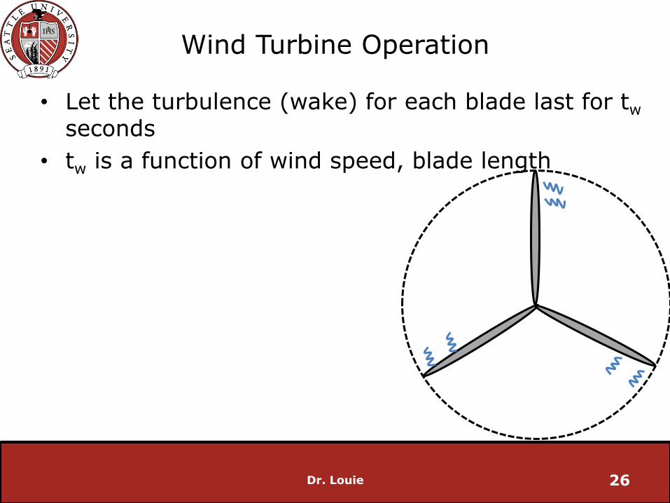
• Let the turbulence (wake) for each blade last for tw
seconds
• tw is a function of wind speed, blade length
Dr. Louie 26
Wind Turbine Operation
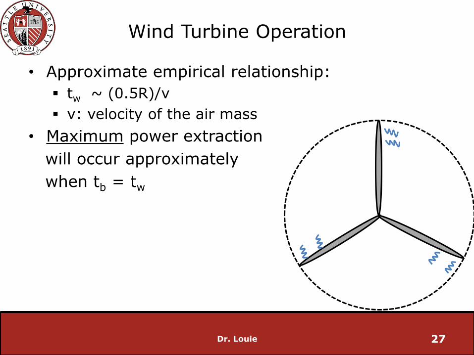
• Approximate empirical relationship:
tw ~ (0.5R)/v
v: velocity of the air mass
• Maximum power extraction
will occur approximately
when tb = tw
Dr. Louie 27

Maximum Power Extraction
• Let
• Where:
l : the tip-speed ratio (sometimes referred to as TSR)
• TSR: the ratio of the speed of the tip of the wind turbine blade to the wind speed of the air before it interacts with the turbine
Dr. Louie 28
U
vl
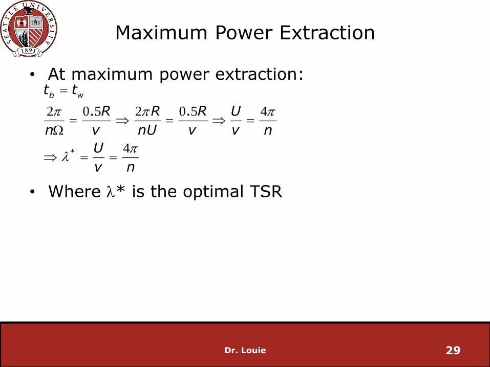
Maximum Power Extraction
• At maximum power extraction:
• Where l* is the optimal TSR
Dr. Louie 29
2 0 5 2 0 5 4
4*
. .
b wt t
R R R U
n v nU v v n
U
v n
l
W

Maximum Power Extraction
• In real life, this derivation underestimates the TSR by about 30%
Optimal TSR ~7-8 for utility scale turbines
• Also note: more blades = lower TSR => slower angular velocity
Dr. Louie 30
2 4* R
n d n
l

Maximum Power Extraction
• At a wind speed of 15 m/s, what is the optimum tip speed of a wind turbine with three 40 m blades?
Dr. Louie 31

Maximum Power Extraction
• At a wind speed of 15 m/s, what is the optimum tip speed of a wind turbine with three 40 m blades?
Dr. Louie 32
4 44 18
3
4 18 15 62 83 141
*
*
.
. . m/s mph
l
l
n
U v
Maximum Power Extraction
• At a wind speed of 30 m/s, what is the optimum tip speed of a wind turbine with one 40 m blade?
Dr. Louie 33
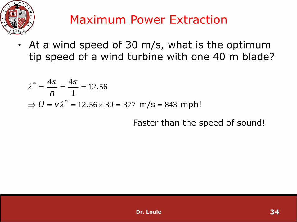
Maximum Power Extraction
• At a wind speed of 30 m/s, what is the optimum tip speed of a wind turbine with one 40 m blade?
Dr. Louie 34
4 412 56
1
12 56 30 377 843
*
*
.
. m/s mph!
n
U v
l
l
Faster than the speed of sound!
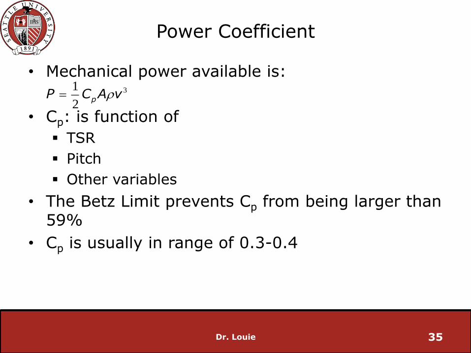
Power Coefficient
• Mechanical power available is:
• Cp: is function of
TSR
Pitch
Other variables
• The Betz Limit prevents Cp from being larger than 59%
• Cp is usually in range of 0.3-0.4
Dr. Louie 35
31
2p
P C A v
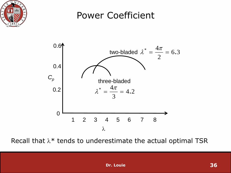
Power Coefficient
Dr. Louie 36
l
Cp
1 2 3 4 5 6 7 80
0.6
0.2
0.4
two-bladed
three-bladed4
4 23
* .
l
46 3
2
* .
l
Recall that l* tends to underestimate the actual optimal TSR

Cp versus TSR
Dr. Louie 37
0 2 4 6 8 10 12 140
0.1
0.2
0.3
0.4
0.5
TSR
Cp
b = 0o
b = 10o
b = 20o
Cp
TSR
31
2( , )l b
m pP C A v
b = pitch angle
Unique TSR maximizes Cp
Note: this is for a specific blade design
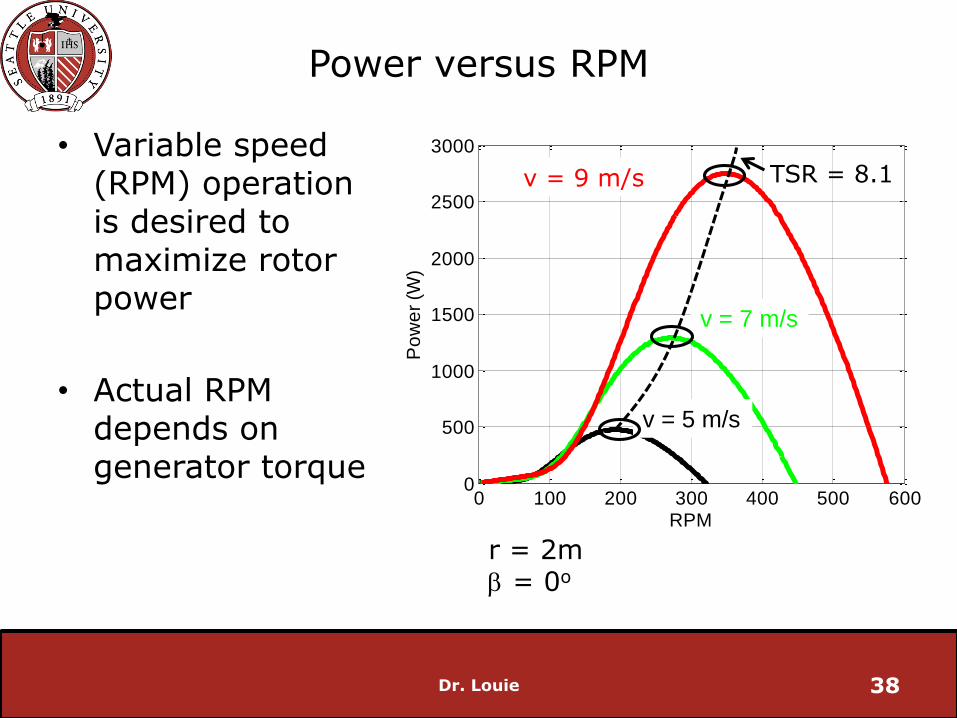
Power versus RPM
• Variable speed (RPM) operation is desired to maximize rotor power
• Actual RPM depends on generator torque
Dr. Louie 38
0 100 200 300 400 500 6000
500
1000
1500
2000
2500
3000
RPM
Po
we
r (W
)
r = 2mb = 0o
v = 9 m/s
v = 7 m/s
v = 5 m/s
TSR = 8.1

Torque
• Power can be expressed as the product of torque (T) and angular velocity
P = WT
• Torque is inversely related to the angular speed for a given power
Dr. Louie 39

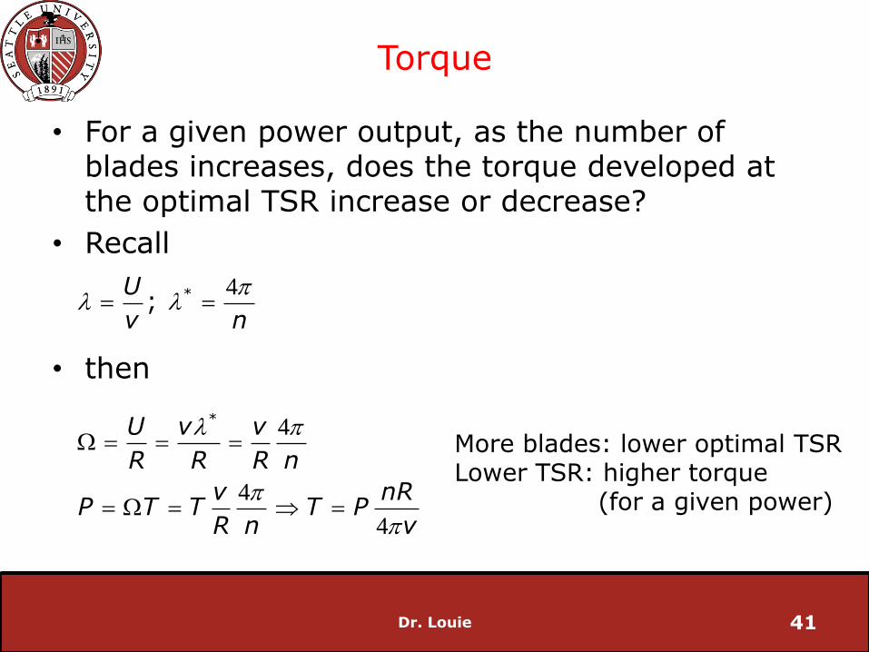
Torque
• For a given power output, as the number of blades increases, does the torque developed at the optimal TSR increase or decrease?
Dr. Louie 40
Torque
• For a given power output, as the number of blades increases, does the torque developed at the optimal TSR increase or decrease?
• Recall
• then
Dr. Louie 41
4
4
4
4
*
*
; U
v n
U v v
R R R n
v nRP T T T P
R n v
l l
l
W
W
More blades: lower optimal TSRLower TSR: higher torque
(for a given power)

Torque
• The more solid the rotor area (number of blades), the higher the starting torque
• The “Little House on the Prairie” style wind turbines are highly solid and used for pumping water
Dr. Louie 42
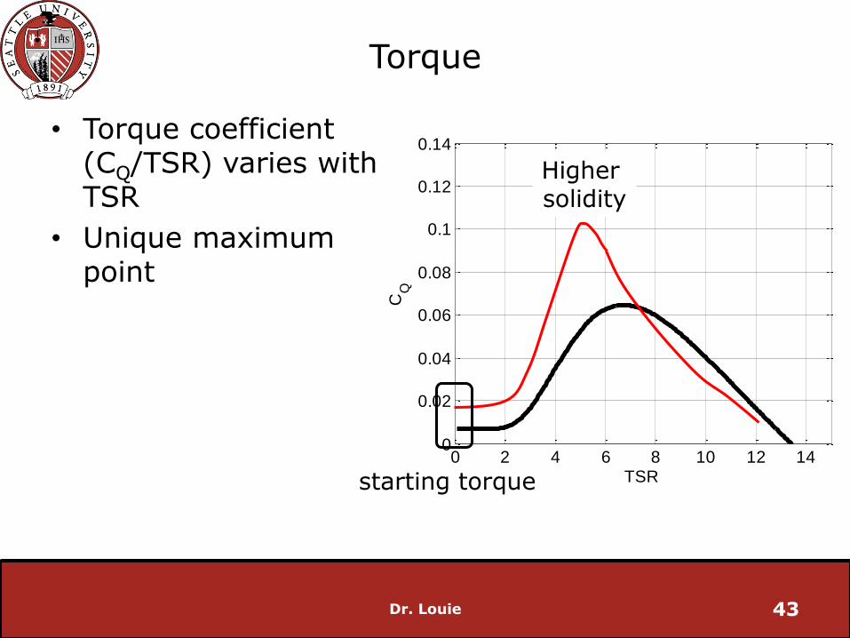
Torque
• Torque coefficient (CQ/TSR) varies with TSR
• Unique maximum point
Dr. Louie 43
0 2 4 6 8 10 12 140
0.02
0.04
0.06
0.08
0.1
0.12
0.14
TSR
CQ
Higher solidity
starting torque
Blade Aerodynamics
• Wind turbine blade design is an active area of research
• We will only discuss the very basics as it relates to wind turbine operation
Dr. Louie 44
Blade Aerodynamics
Dr. Louie 45
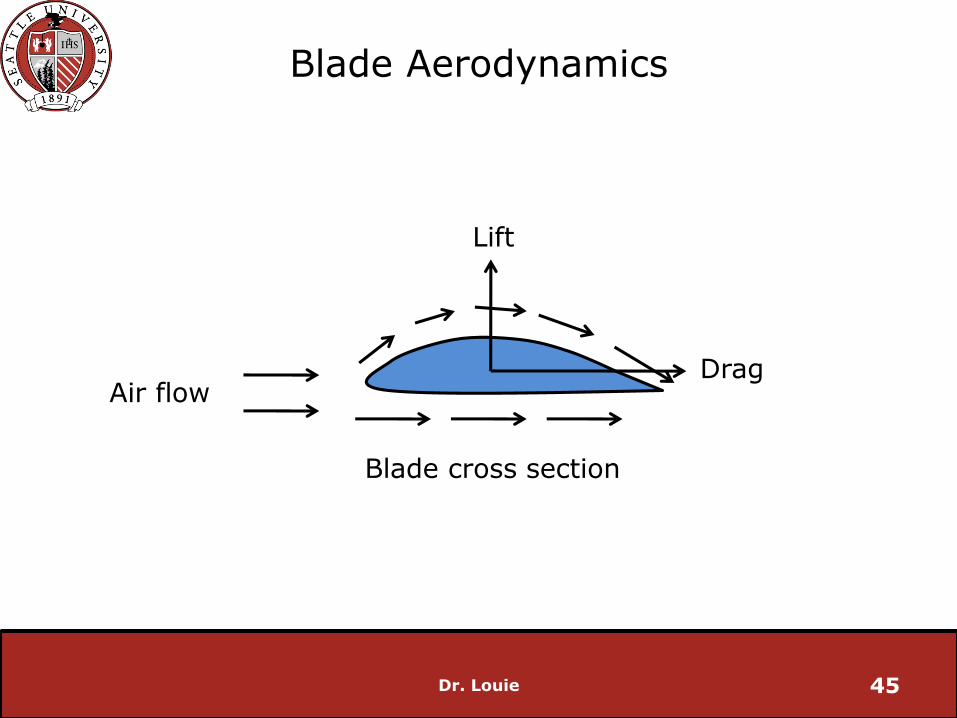
Lift
DragAir flow
Blade cross section
Blade Aerodynamics
Dr. Louie 46
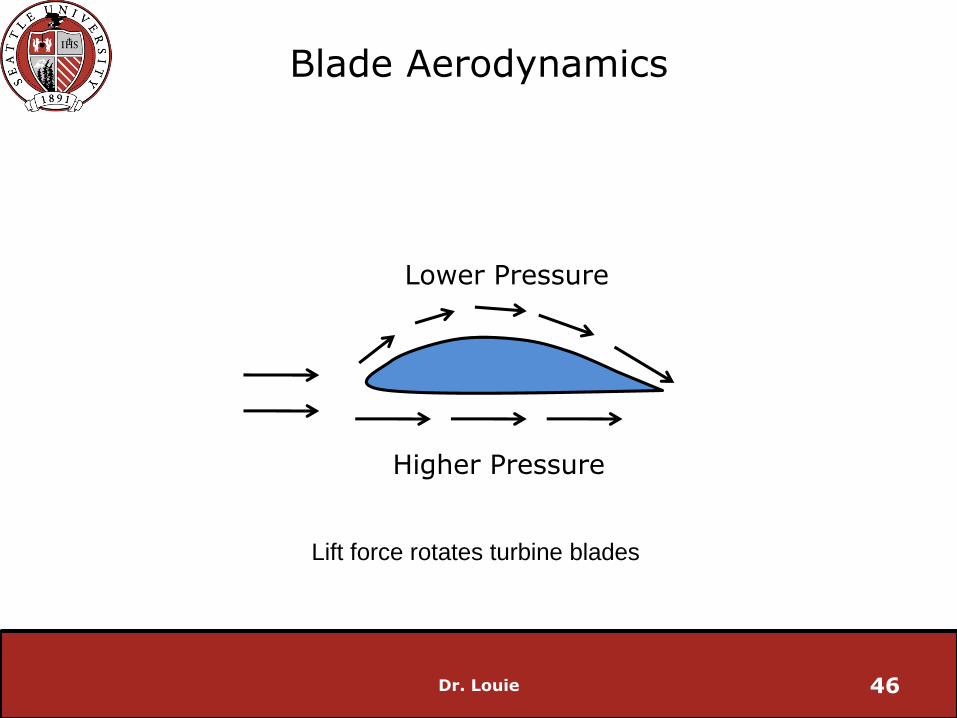
Lower Pressure
Higher Pressure
Lift force rotates turbine blades

Blade Aerodynamics
• Angle of attack: angle between airflow and the chord line of the airfoil
• Increasing angle of attack tends to increase lift
• Some wind turbines adjust their pitch (b) to affect the angle of attack and increase lift
Dr. Louie 47
a
Air flow
chord
Blade Aerodynamics
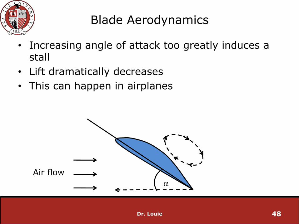
• Increasing angle of attack too greatly induces a stall
• Lift dramatically decreases
• This can happen in airplanes
Dr. Louie 48
a
Air flow
Wind Turbine Operational Speeds
• Two classes of wind turbines
Constant Speed
Variable Speed
• Technology and performance (efficiency) differs for each class
Dr. Louie 49

Constant Speed Wind Turbine
• Rotor rotates at nearly constant speed
may vary by a few percent or less, depending on wind speed
assumes wind is sufficient for rotation to start (different from cut-in speed)
• Uses induction generator to produce electricity
• Rotational speed determined by the generator design (number of poles), grid frequency, gearbox ratio
Dr. Louie 50

Constant Speed Wind Turbine
Dr. Louie 51

Constant Speed Wind Turbine
Dr. Louie 52
For wind turbines, s is negative as the generator’s rotor rotates faster than the synchronous speed
Negative resistance,power is generated
Constant Speed Wind Turbine
• Advantages:
Inexpensive electrical system
Simple design
No harmonics
• Disadvantages:
Optimal TSR is only achieved for one wind speed
Mechanical stresses
Requires grid connection
Noisy
Dr. Louie 53

Constant Speed Wind Turbine
• Wind turbine must be capable of maintaining nearly rated power for wind speeds between rated and cut-out
avoid generator overloading
Dr. Louie 54
0 3 6 9 12 15 18 21 240
0.5
1
1.5
2
pow
er
(MW
)
wind speed (m/s)
Constant Speed Wind Turbine
• Since torque (and hence mechanical power) on a constant speed wind turbine increases with wind speed, need to make the turbine less aerodynamically efficient to maintain nearly constant electrical power output
Need to regulate the power
• Two types of constant speed wind turbines:
Stall regulated (passive)
Pitch regulated
Dr. Louie 55
Stall Regulated, Constant Speed Turbines
• No control necessary
• Blades are aerodynamically designed to become less efficient at high wind speeds
• Angle of attack is increased as wind speed increases, after rated wind speed, the blades stall and the lift force is reduced
• Entirely passive
Dr. Louie 56
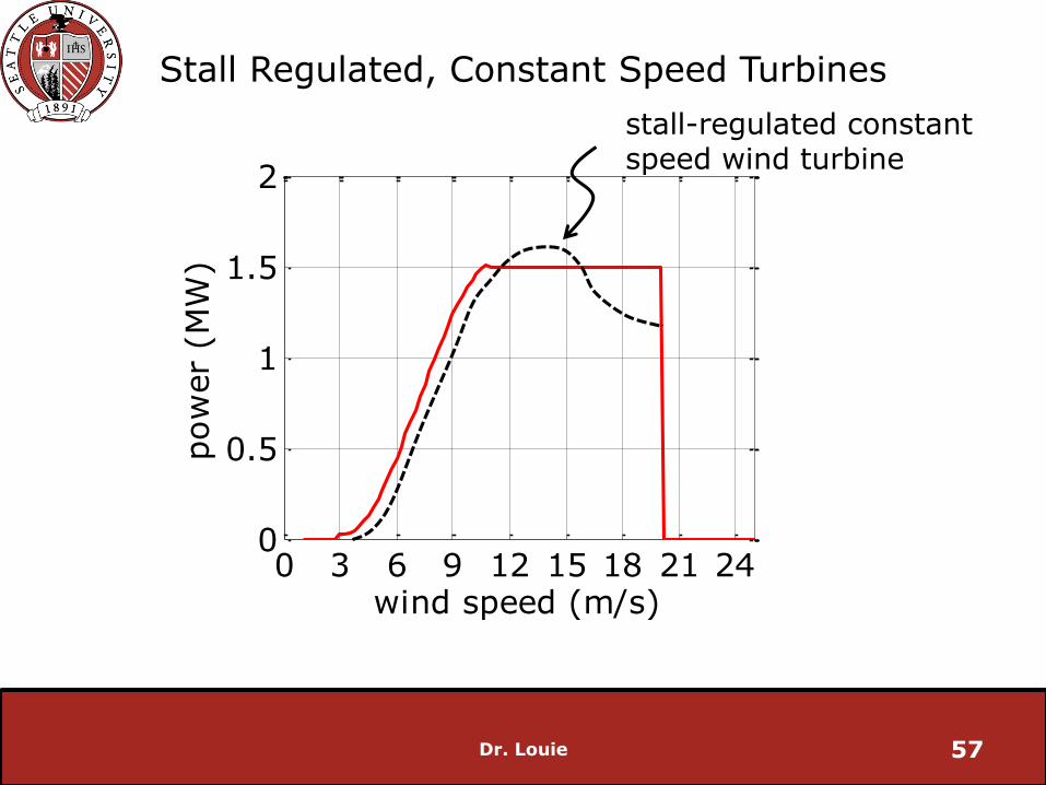
Stall Regulated, Constant Speed Turbines
Dr. Louie 57
0 3 6 9 12 15 18 21 240
0.5
1
1.5
2pow
er
(MW
)
wind speed (m/s)
stall-regulated constant speed wind turbine

Pitch Regulated, Constant Speed Turbines
• Blades rotate along longitudinal axis
• Pitching blades can increase or decrease angle of attack
increase angle of attack at start-up
decrease angle of attack at wind speeds above rated
• lift decreases, less power
Dr. Louie 58
Variable Speed Turbines
• Rotor can rotate over a range of speeds
• Generator:
Wound rotor induction
Doubly fed induction
Variable frequency
• Generator can be controlled for different torque/speed relationships
• Wind turbine blades can be pitch regulated
Dr. Louie 59
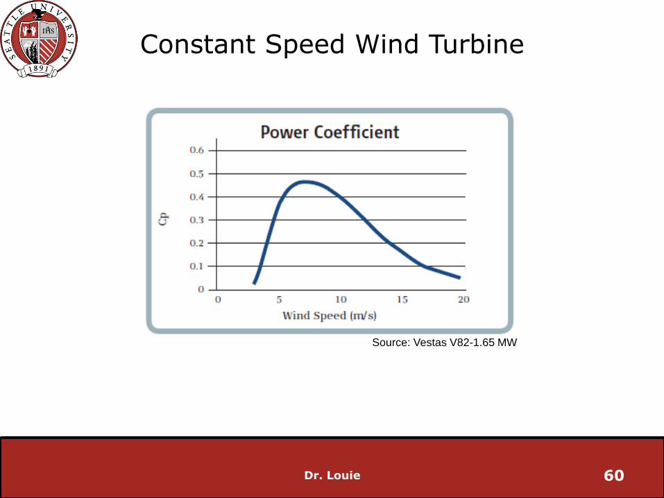
Constant Speed Wind Turbine
Dr. Louie 60
Source: Vestas V82-1.65 MW

Constant Speed Wind Turbine
Dr. Louie 61
Source: Vestas V82-1.65 MW
constant optimal TSR
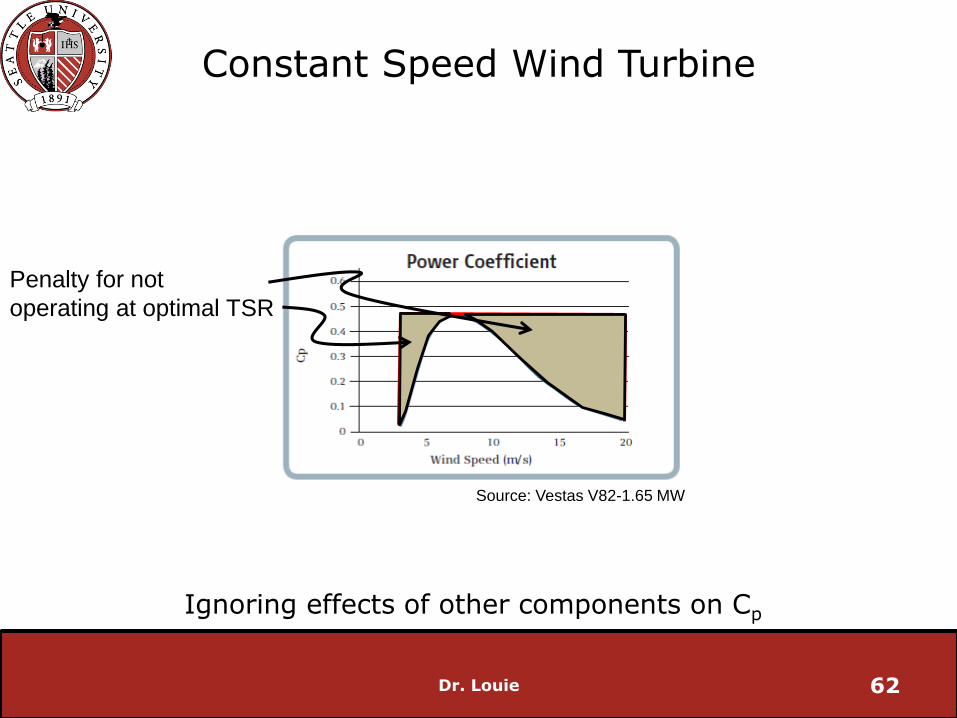
Constant Speed Wind Turbine
Dr. Louie 62
Source: Vestas V82-1.65 MW
Penalty for not
operating at optimal TSR
Ignoring effects of other components on Cp
Variable Speed Turbines
• Low wind speeds: generator torque control used to optimize power
• High wind speeds (above rated): pitch control used
Dr. Louie 63
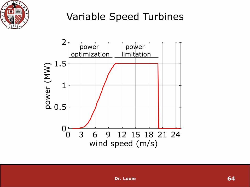
Variable Speed Turbines
Dr. Louie 64
0 3 6 9 12 15 18 21 240
0.5
1
1.5
2pow
er
(MW
)
wind speed (m/s)
power limitation
power optimization
Variable Speed Wind Turbine
• Most new wind turbines are variable speed
• Advantages:
Greater energy conversion (5-15%)
Lower cut-in speed
Aerodynamically efficient
• Disadvantages:
Expensive
Less electrically efficient
Complex control
Dr. Louie 65
Reading
E. DeMeo, W. Grant, M. Milligan and M. Schuerger, “Wind Plant Integration”, Power and Energy Magazine, vol. 3, no. 6, Dec. 2005.
Dr. Louie 66