14 SHI Ge Thermal-Mechanic Behavior Shell BeamBlankMold...
15
ANNUAL REPORT 2008 ANNUAL REPORT 2008 UIUC, August 6, 2008 Thermal-mechanical Behavior of The Solidifying Steel Shell in A Beam blank Solidifying Steel Shell in A Beam-blank Mold and Ideal Taper Design Ge Shi Department of Mechanical Science and Engineering University of Illinois at Urbana-Champaign Outline • Background • Objective • Model Description • Result • Result – Temperature – Shell Thickness – Interfacial gap formation – Stress – Effects of mold distortion Effects of mold distortion • Taper Improvement • Conclusion University of Illinois at Urbana-Champaign • Metals Processing Simulation Lab • Ge Shi 2
Transcript of 14 SHI Ge Thermal-Mechanic Behavior Shell BeamBlankMold...

ANNUAL REPORT 2008ANNUAL REPORT 2008UIUC, August 6, 2008
Thermal-mechanical Behavior of The
Solidifying Steel Shell in A Beam blankSolidifying Steel Shell in A Beam-blank
Mold and Ideal Taper Design
Ge Shi
Department of Mechanical Science and Engineering
University of Illinois at Urbana-Champaign
Outline
• Background
• Objective
• Model Description
• Result• Result– Temperature
– Shell Thickness
– Interfacial gap formation
– Stress
– Effects of mold distortionEffects of mold distortion
• Taper Improvement
• Conclusion
University of Illinois at Urbana-Champaign • Metals Processing Simulation Lab • Ge Shi 2
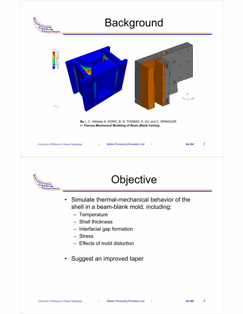
Background
By L. C. Hibbeler S. KORIC, B. G. THOMAS, K. XU, and C. SPANGLERIn Thermo-Mechanical Modeling of Beam Blank Casting
University of Illinois at Urbana-Champaign • Metals Processing Simulation Lab • Ge Shi 3
g g
Objective
• Simulate thermal-mechanical behavior of the shell in a beam blank mold including:shell in a beam-blank mold, including:– Temperature
– Shell thickness
– Interfacial gap formation
– Stress
– Effects of mold distortionEffects of mold distortion
• Suggest an improved taper
University of Illinois at Urbana-Champaign • Metals Processing Simulation Lab • Ge Shi 4

Mold Top View
Mold wide face(i id di )
436
(inside radius)
Flange corner
Flange tip
93mm
436mm
WebMold narrow
facex
y
Shoulder
g p
Annular cooling-Pour Annular coolingwater slotfunnel
Mold wide face(inside radius)
576mm
University of Illinois at Urbana-Champaign • Metals Processing Simulation Lab • Ge Shi 5
By L. C. Hibbeler S. KORIC, B. G. THOMAS, K. XU, and C. SPANGLER in Thermo-Mechanical Modeling of Beam Blank Casting
576mm
Model Domain
Refined section for solidifying shell
Coarse section for liquid
40 [
mm
]
Domain of the Model Mesh
University of Illinois at Urbana-Champaign • Metals Processing Simulation Lab • Ge Shi 6

Heat Transfer Model Eqs.
( )H T∂
• Governing equation
( ) ( )( )H Tk T T
Tρ
∂= ∇ ⋅ ∇
∂
ˆT T( t)= x
• Boundary conditions:
T T( , t)= x
( ) ˆk T q( , t)− ⋅ =n x∇
( )k T h(T T )∞− ⋅ = −∇ n
University of Illinois at Urbana-Champaign • Metals Processing Simulation Lab • Ge Shi 7
• By S. KORIC, B. G. THOMAS, K. XU, and C. SPANGLER In Thermo-Mechanical Model of Continuous Casting of Steel Beam Blanks: Part I Model Formulation and Validation
Mechanical Model Eqs.
1 T∇∇ ˆ A
• Governing equation • Boundary conditions:
])([2
1 Tuu ∇+∇=ε
( ) 0x b∇ ⋅ σ + =u on A
on AΦ
=⋅ =
u u
nσ Φ
• Constitutive equation
thieel εεεε ++=
ie th:( )= − −Dσ ε ε ε
Total strain rate:
Total stress rate:
B
22 (k )
3= μ + − μ ⊗D I I I
Isotropic elasticity tensor :
University of Illinois at Urbana-Champaign • Metals Processing Simulation Lab • Ge Shi 8
• By S. KORIC, B. G. THOMAS, K. XU, and C. SPANGLER In Thermo-Mechanical Model of Continuous Casting of Steel Beam Blanks: Part I Model Formulation and Validation

Boundary Condition
•Surface behavior [DISP]
Thermal distortion
•Contact [GAPCON]
N l b h i –Thermal distortion
–Mold taper
•UMAT
–Normal behavior
–Thermal conductance
•Surface load [DLOAD]
University of Illinois at Urbana-Champaign • Metals Processing Simulation Lab • Ge Shi 9
–Material properties
–Mushzone specification
–Ferrostatic pressure
Interface Heat Flux
( )"q (h h ) T T= − + −• Water ( )gap c rad shell moldq (h h ) T T= +
Conduction
• Water
• mold
• Powder
powair
c mold air pow shell
dd1 1 1
h h k k h= + + +
• Air gap
• Shell
( )( )8
2 25.67 10h T T T T
−×= + +
Radiation
( )( )rad shell mold shell mold
m s
h T T T T1 1
1= + +
+ −ε ε
University of Illinois at Urbana-Champaign • Metals Processing Simulation Lab • Ge Shi 10
• By S. KORIC, B. G. THOMAS, K. XU, and C. SPANGLER In Thermo-Mechanical Model of Continuous Casting of Steel Beam Blanks: Part I Model Formulation and Validation
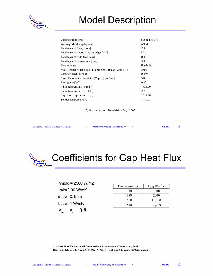
Model Description________________________________________________________________________
Casting strand [mm] 576 x 436 x 93
W ki M ld l th [ ] 660 4Working Mold length [mm] 660.4
Total taper at flange [mm] 2.33
Total taper at sloped shoulder edge [mm] -2.22
Total taper at wide face [mm] 0.48
T t l t t f [ ] 3 0Total taper at narrow face [mm] 3.0
Type of taper Parabolic
Mold contact resistance feat coefficient, hmold [W/m2/K] 2500
Casting speed [m/min] 0.889
M ld Th l C d ti it (C ) [W/ K] 370Mold Thermal Conductivity (Copper) [W/mK] 370
Steel grade [%C] 0.071
Initial temperature strand [C] 1523.70
Initial temperature mold [C] 285
Li id [C] 1518 70Liquidus temperature [C] 1518.70
Solidus temperature [C] 1471.95
________________________________________________________________________
By Koric et al, Int J Num Meths Eng., 2007
University of Illinois at Urbana-Champaign • Metals Processing Simulation Lab • Ge Shi 11
y , g ,
Coefficients for Gap Heat Flux
hmold = 2500 W/m2
kair=0.06 W/mK
dpow=0.1mm
Temperature, oC hshell, W/m2K
1030 1000 1150 2000 p
kpow=1 W/mK 1518 10,000
1530 20,000
m s 0.8ε = ε =
J. K. Park, B. G. Thomas, and I. Samarasekera: Ironmaking and Steelmaking, 2002
H H N J E L T J Y Y M W K Ki K H Oh d J K Y ISIJ I t ti l
University of Illinois at Urbana-Champaign • Metals Processing Simulation Lab • Ge Shi 12
Han, H. N., J. E. Lee, T. J. Yeo, Y. M. Won, K. Kim, K. H. Oh and J. K. Yoon: ISIJ International

Simulation Result
University of Illinois at Urbana-Champaign • Metals Processing Simulation Lab • Ge Shi 13
Temperature Results
Temperature Contour of Strand at Temperature Contour of Strand 459 [mm] Below Meniscus
pat 660 [mm] Below Meniscus
University of Illinois at Urbana-Champaign • Metals Processing Simulation Lab • Ge Shi 14

Temperature HistoriesTemperature Histories for The Points on Shell Perimeter
Reheating Reheating
11, 12 overlapping
University of Illinois at Urbana-Champaign • Metals Processing Simulation Lab • Ge Shi 15
Cooling Rate
291.74 mm Below Meniscus
344.34 mm Below Meniscus
408.79 mm Below Meniscus
6 0
University of Illinois at Urbana-Champaign • Metals Processing Simulation Lab • Ge Shi 16
565.70 mm Below Meniscus
662.16 mm Below Meniscus
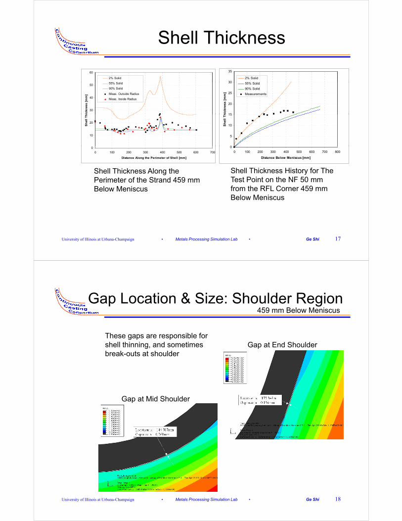
Shell Thickness
60
2% Solid
55% S lid 30
35
2% Solid
55% S lid
30
40
50ic
knes
s [m
m]
55% Solid
90% Solid
Meas. Outside Radius
Meas. Inside Radius
15
20
25
30
hic
knes
s [m
m]
55% Solid
90% Solid
Measurements
10
20
Sh
ell
Th
0
5
10
15
Sh
ell
Th
Shell Thickness Along the P i t f th St d 459
Shell Thickness History for The T t P i t th NF 50
0
0 100 200 300 400 500 600 700
Distance Along the Perimeter of Shell [mm]
0
0 100 200 300 400 500 600 700 800
Distance Below Meniscus [mm]
Perimeter of the Strand 459 mm Below Meniscus
Test Point on the NF 50 mm from the RFL Corner 459 mm Below Meniscus
University of Illinois at Urbana-Champaign • Metals Processing Simulation Lab • Ge Shi 17
Gap Location & Size: Shoulder Region459 mm Below Meniscus
G t E d Sh ld
459 mm Below Meniscus
These gaps are responsible for h ll thi i d ti Gap at End Shouldershell thinning, and sometimes
break-outs at shoulder
Gap at Mid Shoulder
University of Illinois at Urbana-Champaign • Metals Processing Simulation Lab • Ge Shi 18
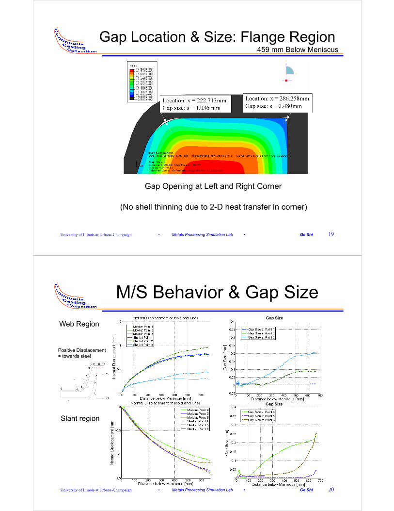
Gap Location & Size: Flange Region459 mm Below Meniscus459 mm Below Meniscus
Gap Opening at Left and Right Corner
(No shell thinning due to 2 D heat transfer in corner)
University of Illinois at Urbana-Champaign • Metals Processing Simulation Lab • Ge Shi 19
(No shell thinning due to 2-D heat transfer in corner)
M/S Behavior & Gap SizeGap Size
Web Region
Positive Displacement = towards steel
Gap Size
Slant region
University of Illinois at Urbana-Champaign • Metals Processing Simulation Lab • Ge Shi 20

M/S Behavior & Gap SizeGap Size
Flange region
Positive Displacement = towards steel
Gap Size
NF region
University of Illinois at Urbana-Champaign • Metals Processing Simulation Lab • Ge Shi 21
Tangential Displacement
Web region Slant region
Positive Displacement p= Away from Point 10 towards centerline
NF regionFlange region
University of Illinois at Urbana-Champaign • Metals Processing Simulation Lab • Ge Shi 22

Stress
Maximum Principal Stress Contour 459 mm Below Meniscus
Maximum Principal Stress Contour 660 mm Below Meniscus459 mm Below Meniscus Contour 660 mm Below Meniscus
University of Illinois at Urbana-Champaign • Metals Processing Simulation Lab • Ge Shi 23
Effects of Mold Distortion
Web region Slant region
NF regionFlange region
10,11,12 Overlapping
University of Illinois at Urbana-Champaign • Metals Processing Simulation Lab • Ge Shi 24

Taper Analysis
• Shoulder Gap Formation Mechanisms
Slant region
Mechanisms– Too much flange taper (A):
pushing shell along slant, causing buckling at shoulderg g
– Too much negative taper of B’
TT
AWB’
University of Illinois at Urbana-Champaign • Metals Processing Simulation Lab • Ge Shi 25
B
B’
Taper Improvement
T• Keep taper on Aunchanged
AW
• Increase taper on W by 0.3 mm at the bottom
• Increase taper on B by 0 4 t th b tt
B
B’
0.4 mm at the bottom
• Decrease taper on B’ by 0.8 mm at the bottom
• Increase taper on T by B• Increase taper on T by 0.3 mm at the bottom
NF region (B)Flange region (A)Web region (W) Slant region (T, B’)
University of Illinois at Urbana-Champaign • Metals Processing Simulation Lab • Ge Shi 26

Improved Taper Recommendations
7
8
Original Taper on A
Original Taper on B
Original Taper on W
Original Taper on T2.5
3
Original Taper
Improved Taper on A
Improved Taper on B
4
5
6
Tap
er*
[mm
]Original Taper on T
Original Taper on B'
Improved Taper on A
Improved Taper on B
Improved Taper on W
Improved Taper on T
Improved Taper on B'1.5
2
per
[%
/m]
Improved Taper on W
Improved Taper on T
Improved Taper on B'
1
2
3
To
tal
T
0.5
1
Tap
0
0 100 200 300 400 500 600 700 800
Distance Below Meniscus [mm]
( )1000 / %
2topD D z
Taper mm mD
−= ×( )topTaper D D z= −
0
0 100 200 300 400 500 600 700 800
Distance Below Meniscus [mm]
2 bottom
pz D⋅ ⋅
University of Illinois at Urbana-Champaign • Metals Processing Simulation Lab • Ge Shi 27
*Note: total taper includes both sides of the mold for A, B, W, and B’D = A, B, W, T, or B’
Summary of Taper
Original Improved
Top [mm] Bottom [mm] Taper [ %/m] Top [mm] Bottom [mm] Taper [ %/m]
A 436.336 430.530 0.948167 436.336 430.530 0.948167
B 576.633 568.960 0.948159 576.633 568.545 1.000168
W 93.447 92.202 0.949003 93.447 91.890 1.190932
T 70.536 69.596 0.949357 70.536 69.284 1.270224
B’ 323.069 318.770 0.948036 323.069 319.601 0.762780
• Increase Taper B to decrease the right corner gap in x direction• Increase Taper B to decrease the right corner gap in x direction
• Increase Taper W to decrease the shoulder gap in y direction
• Increase Taper T decrease the corner gaps in x direction
• Decrease Taper B’ to decrease the shoulder gap by lessening• Decrease Taper B to decrease the shoulder gap, by lessening tangential sliding around corner
• Keep Taper A unchanged to balance between enlarging corner gaps in y direction (if too small) and pushing the shell tangentially along
University of Illinois at Urbana-Champaign • Metals Processing Simulation Lab • Ge Shi 28
y ( ) p g g y gslant (if too large).
Conclusion
• Four gaps are predicted along the mold / shell perimeter: the middle and end of shoulder and at both flange corners.the middle and end of shoulder and at both flange corners.
• Heat transfer at gap locations slows down, causing reheating especially at the shoulder where the local shellreheating, especially at the shoulder, where the local shell thickness is reduced dangerously. (Flange corners stay thick owing to 2-D heat transfer.)
• The thermal distortion has a minor but significant effect half-way down mold, where it is maximum.
• An improved taper design is proposed.
University of Illinois at Urbana-Champaign • Metals Processing Simulation Lab • Ge Shi 29
Acknowledgements
• Professor Brian. G. Thomas, Seid Koric, Lance Hibbeler
• Continuous Casting Consortium Members (Nucor, Postech, LWB Refractories, Corus, Labein, Arcelor-Mittal, Baosteel, Steel Dynamics, Postech, ANSYS)Baosteel, Steel Dynamics, Postech, ANSYS)
• National Science Foundation
• National Center for Supercomputing Applications (NCSA) at UIUC
• HKS (ABAQUS)
University of Illinois at Urbana-Champaign • Metals Processing Simulation Lab • Ge Shi 30