14 OOFS - ruben-group · JWST261-c14 JWST261-Halcrow Printer: Markono October 26, 2012 15:36 Trim:...
30
JWST261-c14 JWST261-Halcrow Printer: Markono October 26, 2012 15:36 Trim: 246mm × 189mm UNCORRECTED PROOFS 14 Nanoparticles, Thin Films and Surface Patterns from Spin-Crossover Materials and Electrical Spin State Control Paulo Nuno Martinho, Cyril Rajnak and Mario Ruben Institute of Nanotechnology, Karlsruhe Institute of Technology 14.1 Introduction Since the report of the first example of a spin-crossover (SCO) complex in 1931 by Cambi and co-workers 1 and the vision of Kahn and co-workers in 1996 towards the application of SCO compounds in data process- ing, 2 a long and impressive literature on SCO has developed with the discovery of several new examples of SCO compounds, the explanation of different types of SCO profiles, and the modification of SCO examples to increase cooperativity and to direct the application to materials science. Scientists have developed SCO networks, 3–5 SCO frameworks, 6–8 SCO gels, 9–11 SCO liquid crystals, 12–14 SCO nanoparticles and nanocrys- tals, SCO thin films and have also applied patterning techniques to fabricate SCO devices. More recently electrical control of SCO has been achieved and this work reviews research made so far with concern to nanoparticles, thin films, surface patterns and devices from SCO materials. SCO complexes are a particular class of compounds of 3d 4 to 3d 7 transition metals ions in an octahedral (O h ) field, which can interchange between two electronic states, high spin (HS) and low spin (LS), by application of an external perturbation such as temperature, pressure, light or magnetic field. 15 This property can be either present in solution or solid state and while in solution the system is diluted and the process essentially molecular, in solid state the process may involve elastic interactions conferring different types and shapes of transition curves. SCO was first reported by Cambi and co-workers when they observed unusual magnetism in iron(III) derivatives of various dithiocarbamates which resulted in the recognition of the interconversion of two spin states as a result of variation in temperature. 1, 16, 17 Despite this discovery in the early 1930s a boom Spin-Crossover Materials: Properties and Applications, First Edition. Edited by Malcolm A. Halcrow. © 2013 John Wiley & Sons, Ltd. Published 2013 by John Wiley & Sons, Ltd. 375
Transcript of 14 OOFS - ruben-group · JWST261-c14 JWST261-Halcrow Printer: Markono October 26, 2012 15:36 Trim:...

JWST261-c14 JWST261-Halcrow Printer: Markono October 26, 2012 15:36 Trim: 246mm × 189mm
UN
CO
RR
EC
TE
DPR
OO
FS
14Nanoparticles, Thin Films and Surface
Patterns from Spin-Crossover Materials andElectrical Spin State Control
Paulo Nuno Martinho, Cyril Rajnak and Mario Ruben
Institute of Nanotechnology, Karlsruhe Institute of Technology
14.1 Introduction
Since the report of the first example of a spin-crossover (SCO) complex in 1931 by Cambi and co-workers1
and the vision of Kahn and co-workers in 1996 towards the application of SCO compounds in data process-ing,2 a long and impressive literature on SCO has developed with the discovery of several new examples ofSCO compounds, the explanation of different types of SCO profiles, and the modification of SCO examplesto increase cooperativity and to direct the application to materials science. Scientists have developed SCOnetworks,3–5 SCO frameworks,6–8 SCO gels,9–11 SCO liquid crystals,12–14 SCO nanoparticles and nanocrys-tals, SCO thin films and have also applied patterning techniques to fabricate SCO devices. More recentlyelectrical control of SCO has been achieved and this work reviews research made so far with concern tonanoparticles, thin films, surface patterns and devices from SCO materials.
SCO complexes are a particular class of compounds of 3d4 to 3d7 transition metals ions in an octahedral (Oh)field, which can interchange between two electronic states, high spin (HS) and low spin (LS), by applicationof an external perturbation such as temperature, pressure, light or magnetic field.15 This property can beeither present in solution or solid state and while in solution the system is diluted and the process essentiallymolecular, in solid state the process may involve elastic interactions conferring different types and shapes oftransition curves. SCO was first reported by Cambi and co-workers when they observed unusual magnetismin iron(III) derivatives of various dithiocarbamates which resulted in the recognition of the interconversion oftwo spin states as a result of variation in temperature.1, 16, 17 Despite this discovery in the early 1930s a boom
Spin-Crossover Materials: Properties and Applications, First Edition. Edited by Malcolm A. Halcrow.© 2013 John Wiley & Sons, Ltd. Published 2013 by John Wiley & Sons, Ltd.
375

JWST261-c14 JWST261-Halcrow Printer: Markono October 26, 2012 15:36 Trim: 246mm × 189mm
UN
CO
RR
EC
TE
DPR
OO
FS
376 Spin-Crossover Materials
in SCO research has only occurred in the last 15 years with the miniaturisation of electronic devices and theapproach of the superparamagnetic limit for magnetic materials.
14.2 Nanoparticles and Nanocrystals
A key factor in the application of SCO systems into materials development is the control of the size of the objectthat displays hysteresis.18 For production of functional devices, the use of nanometre-range SCO materialsis required and, combined with this, their magnetic and cooperative behaviour should be retained at lowdimensions. SCO nanoparticles have been produced that mainly recur to two distinct families of compounds:the [Fe(R-trz)3]X2 family (trz = 1,2,4-triazole) and the [Fe(pz)]{M(CN)4} family (pz = pyrazole). The resultsobtained for SCO nanoparticles derived from [Fe(R-trz)3]X2 (Fig. 14.1) have been very interesting.
14.2.1 Reverse Micelle (Microemulsion) Technique
In this technique, the resultant particle volume is defined by the size of the water droplet within the emulsion.The most effective way to control the water droplet size is to vary the relative ratio of the water-to-oil, suchthat smaller droplets are formed when the amount of oil is increased.19, 20
Diverse techniques have been used to produce SCO nanoparticles but undoubtedly the most widely usedhas been the reverse micelle method, Fig. 14.1. This section reviews work done to produce SCO nanoparticlesusing reverse micelle, dispersion and sol-gel techniques.
14.2.1.1 Triazole Derivatives
Coronado pioneered the preparation of SCO nanoparticles using the reverse micelle type technique, whichused either a water-in-oil or ethanol-in-oil microemulsion to grow SCO nanoparticles of [Fe(Htrz)2(trz)](BF4)which were purple in colour and with an average size of around 15 nm.21 Evaporation of the solvent produceda solid that could be suspended in n-octane yielding a bright transparent suspension. The thermochromicbehaviour of such suspensions was investigated, with the nanoparticles presenting a colour change associatedwith both HS (pink) and LS (colourless) states. Transmission electron microscopy (TEM) images of isolatedparticles showed regular sized spherical nanoparticles, Fig. 14.2a. Magnetic investigation of the isolated
R
R
Fe Fe Fe
N
N N
NN N
N N
N
R
R
Bidendate ligand NH2 trz
NH2
Iron(II) salt FeBr2
R
N
N N
N
N
N N
N N
N N
N
R
Figure 14.1 Iron(II) triazole-nanoparticles. (Left) representation of main family of compounds ([Fe(R-trz)3]X2)used to produce SCO nanoparticles; (right) synthetic route used to produce nanoparticles of [Fe(NH2-trz)3].Reproduced from ref. 22. Copyright Royal Society of Chemistry.

JWST261-c14 JWST261-Halcrow Printer: Markono October 26, 2012 15:36 Trim: 246mm × 189mm
UN
CO
RR
EC
TE
DPR
OO
FS
Nanoparticles, Thin Films and Surface Patterns from SCO Materials and Electrical Spin State Control 377
(a)
(b)(d)
(c) a)50
40
30
20
20 40 60 80Size (nm)
100 120 140
Par
ticle
s
10
0
b)
3.0
2.5
2.0
1.5
1.0
0.5
3.0
3.5
1.0
0.8
0.6
0.4
0.2
2.5
2.0
1.5
1.0
0.5
0.0320 260 280 300
Temperature / KT (K)
320 340 360330 340 350 360 370 380 390 400
1st cycle
2nd cycle
3rd cycle
4th cycle
200 nm
χT (
emu.
K.m
ol–1
χ M T
/Km
ol–1
cm–3
γ HS
Figure 14.2 SCO nanoparticles of ([Fe(R-trz)3]X2: (a) TEM image of [Fe(Htrz)2(trz)](BF4) nanoparticles; (b)magnetic thermal hysteresis of [Fe(Htrz)2(trz)](BF4) nanoparticles with 1st cycle represented by black circles,2nd cycle represented by red squares, 3rd cycle represented by blue triangle and 4th cycle represented by yellowdiamonds;21 (c) TEM image of [Fe(NH2trz)3](Br)2·3H2O·0.03(surfactant) nanoparticles with statistic distributionbased TEM images on ca. 300 particles, showing average size 69 nm, minimum and maximum sizes, 26 and147 nm and disparity 19 nm; (d) Magnetic plot of [Fe(NH2trz)3](Br2)·3H2O·0.03(surfactant) for nanoparticles (-)and for macroscopic particles obtained from a typical synthesis (–). Reproduced from refs 21 and 22. CopyrightWiley VCH and the Royal Society of Chemistry.
nanoparticles showed that both the transition temperature (T1/2↑ = 386 K and T1/2↓ = 343 K) and the large43 K wide hysteresis window were preserved when compared to the original nonengineered powder samples,Fig. 14.2b.
In a parallel development Letard et al. prepared nanoparticles of a related compound where the triazole isappended with an amino function and the bromide salt is used, [Fe(NH2-trz)3](Br)2·3H2O.0.03(surfactant =Lauropal).22 In contrast to the nanoparticles previously described, their hysteresis window is preserved onlyfor large particles (>50 nm). It is interesting that these authors used a nonionic surfactant in contrast tosodium dioctyl sulfosuccinate used by Coronado and co-workers. TEM images of isolated nanoparticlesdispersed in an ethanol solution, showed a good distribution of spherical particles with an average size of69 nm, Fig. 14.2c.
Magnetic measurements for a collection of nanoparticles in both cooling and warming modes showed an 8 Kwide hysteretic SCO system (T1/2↑ = 311 K and T1/2↓ = 303 K). When compared to the macroscopic particles(bulk sample) it was possible to observe that the width of the hysteresis window and consequently the degreeof cooperativity decreases for the nanoparticles, Fig. 14.2d. In a follow up, Letard and co-workers applied the

JWST261-c14 JWST261-Halcrow Printer: Markono October 26, 2012 15:36 Trim: 246mm × 189mm
UN
CO
RR
EC
TE
DPR
OO
FS
378 Spin-Crossover Materials
same reverse micelle technique to the previously studied system and analysed the influence of the particle sizeon the SCO properties.23 In a controlled fashion, particles with different sizes were produced by changingthe surfactant/water ratio. TEM images of the particles as function of the surfactant/water percentage rangingfrom 50–85% were obtained, Fig. 14.3a. The authors concluded that homogeneity increases and particle sizedecreases with increasing proportions of surfactant, yielding 30 nm size nanoparticles when 85% of surfactantwas used.
The magnetic properties in cooling and warming modes as a function of surfactant/water percentage weredetermined, Fig. 14.3b. The abruptness of the transition was quantified using a parameter introduced by theauthors (�T80), corresponding to the difference of temperature at which 80 and 20% of the iron(II) metal ionsundergo spin-transition. Examination of the magnetic plots concluded that although the transition temperatureis not strongly influenced by the size of the particles, the width of the hysteresis is strongly dependent on thesize of the particles. The authors also pointed out that irrespective of the particle size the materials displaya large absorption shoulder at around 520 nm, as a result of the d–d transition of the LS state (1A1g→1T1g).The d–d transition of the HS state (5T2g→5Eg) is expected to be observed at lower energy at 830 nm.
Recently, Coronado and Galan-Mascaros have studied the effect of chemical and size tuningon the thermal hysteresis of bistable SCO nanoparticles. Nanoparticles of [Fe(Htrz)2(trz)](BF4),[Fe(Htrz)3-x(NH2trz)x](ClO4)2 and [Fe0.8Zn0.2(Htrz)2(trz)](BF4) were prepared using the reverse micelle tech-nique. The authors observed that mean size of the [Fe(Htrz)2(trz)](BF4) nanoparticles can be tuned down to 6nm in diameter, with a considerable homogeneity shown by the narrow size distribution. The abruptness of theSCO was not affected by tuning down the size of the nanoparticles, which maintained thermal hysteresis loopwidths of 30–40 K. Doped nanoparticles, [Fe(Htrz)3-x(NH2trz)x](ClO4)2 and [Fe0.8Zn0.2(Htrz)2(trz)](BF4),presented sizes ranging from 10–15 nm with SCO temperatures closer to room temperature and thermalhysteresis loops narrower than the ones produced by undoped nanoparticles (15–20 K). TEM, Fig. 14.4a–c,and atomic force microscopy (AFM), Fig. 14.4d and Fig.14.4e, after deposition on gold or silicon surfaceswere used to characterise produced nanoparticles.24
Bousseksou et al. also contributed considerably to advance the research on SCO nanoparticles by prepar-ing nanoparticles of [Fe(NH2trz)3](tos)2 (tos = tosylate) doped with fluorescent Rhodamine 110 (Rh110),Fig. 14.5.25 The authors choose Rh110 as fluorescent marker because this exhibits only a very weak thermalextinction of its luminescence around room temperature. Its emission spectrum and the low energy tail of itsexcitation spectrum both overlap the 1A1g→1T1g absorption band of the iron(II)-triazole complex. Finally,Rh110 also exhibits relatively weak photobleaching, and its properties within reverse micelles had beenpreviously explored by others.26
Undoped nanoparticles showed reversible thermochromic behaviour, with a violet suspension turningcolourless when heated to 50 ◦C which indicated possible SCO behaviour, Fig. 14.5a. Fluorescence of 10(6) nmnanoparticles of [Fe(NH2trz)3](tos)2 doped with 3% Rh110, and 3 nm nanoparticles of [Fe(NH2trz)3](NO3)2
doped with 0.01% Rh110, were investigated. The thermal variation of the fluorescence intensity at 540 nmshowed that for [Fe(NH2trz)3](tos)2 doped with 3% of Rh110, the transition temperatures are 301 and 306 Kin the heating and cooling modes, respectively. In contrast to what would be expected, the authors observedthat the emission intensity increases with the temperature. In the case of [Fe(NH2trz)3](NO3)2 nanoparticlesdoped with 0.01% of Rh110, the absence of hysteresis allowed the authors to develop a thermometer forreal-time thermometry, Fig. 14.5c.
In parallel to the developments on fluorescent SCO nanoparticles, Bousseksou and co-workers also inves-tigated the cooperative SCO phenomena in [Fe(NH2trz)3](tos)2 nanoparticles.27 Particles with 3–4 nm sizewere obtained using a nonionic surfactant to avoid anion exchange. TEM, high-resolution transmissionelectron microscopy (HRTEM), dynamic light scattering (DLS), UV-vis spectroscopy and magnetic mea-surements were used to characterise dried particles and particles in suspension. TEM images of nanoparticlesof [Fe(NH2trz)3](tos)2 show similar, spherical, nonaggregated nanoparticles with a narrow size distribution.

JWST261-c14 JWST261-Halcrow Printer: Markono October 26, 2012 15:36 Trim: 246mm × 189mm
UN
CO
RR
EC
TE
DPR
OO
FS
(a)
(b)
Siz
e / n
m
40 30 20 10 00
010
020
030
040
050
060
020
040
060
080
010
0012
0014
00
4050
%
500
nm
500
nm
500
nm
200
nm
200
nm50
nm
70%
77%
73%
80%
85%
30 20 10 0
4050 30 20 10 0
405060 30 20 10 0
30 20 Particles 10 0
30 20 10 0
050
100
150
200
050
100
150
200
050
100
150
200
050
100
150
200
220
240
260
280
300
320
340
220
240
260
280
300
320
340
220
240
260
280
300
320
340
220
240
260
280
300
320
340
220
χMT/cm3 K mol–1χMT/cm3 K mol–1χMT/cm3 K mol–1
∂(χMT)/∂T
∂(χMT)/∂T
∂(χMT)/∂T
∂(χMT)/∂T
∂(χMT)/∂T
∂(χMT)/∂T
240
260
280
300
320
340
Tem
pera
ture
/K220
240
260
280
300
320
340
T/K
T/K
T/K
T/K
T/K
T/K
0.0
0.1
0.2
0.3
0.4 20
030
032
034
020
030
032
034
0
200
300
320
340
200
300
320
340
200
300
320
340
200
300
320
340
0.00
0.20
0.15
0.10
0.05
0.00
0.15
0.10
0.05
0.0
0.1
0.2
0.3
Trad
ition
al, >
µm50
%, 1
.2µm
70%
, ~20
0nm
77%
, ~70
nm
80%
, ~50
nm85
%, ~
30nm
0.0
0.5
1.0
1.5
2.0
2.5
3.0
3.5
0.0
0.5
1.0
1.5
2.0
2.5
3.0
3.5
0.0
0.5
1.0
1.5
2.0
2.5
3.0
3.5
χ
Figu
re14
.3Si
zedi
strib
utio
nof
[Fe(
NH
2tr
z)3]B
r 2na
nopa
rtic
les:
(a)
Num
ber
ofpa
rtic
les
vers
uspa
rtic
lesi
zes
from
TEM
imag
esof
nano
part
icle
spr
epar
edby
are
vers
em
icel
lem
etho
das
func
tion
ofth
esu
rfac
tant
/wat
erpe
rcen
tage
.Sta
tistic
dist
ribut
ion
eval
uate
dac
cord
ing
TEM
imag
eson
arou
nd30
0pa
rtic
les;
(b)
mag
netic
plot
sof
[Fe(
NH
2tr
z)3]B
r 2·y(
surf
acta
nt)
for
the
mac
rosc
opic
part
icle
spr
epar
edon
trad
ition
alw
ayan
dfo
rna
nopa
rtic
les
depe
ndin
gof
the
surf
acta
nt/w
ater
ratio
.Rep
rodu
ced
from
ref.
23.C
opyr
ight
Wile
y/VC
H.
379

JWST261-c14 JWST261-Halcrow Printer: Markono October 26, 2012 15:36 Trim: 246mm × 189mm
UN
CO
RR
EC
TE
DPR
OO
FS
380 Spin-Crossover Materials
(a)
(b)
(e)
(c)
(d)
Figure 14.4 Structural characterisation of SCO nanoparticles: (a) TEM image of NPs of [Fe(Htrz)2(trz)](BF4);(b) TEM image of NPs of [Fe(Htrz)3-x(NH2trz)x](ClO4)2; (c) TEM image of NPs of [Fe0.8Zn0.2(Htrz)2(trz)](BF4);(d) AFM images of nanoparticles of [Fe(Htrz)2(trz)](BF4) on a gold substrate (left) and on a silicon substrate(right); (e) AFM high resolution topography image of nanoparticles of [Fe(Htrz)2(trz)](BF4) on a gold substrate.Reproduced from ref. 24. Copyright American Chemical Society.
This was further confirmed by DLS at room temperature. The SCO behaviour of such particles was investi-gated by variable temperature UV-vis experiments by following the change in intensity of the LS absorptionpeak centred at 540 nm. Thermal SCO curves of [Fe(NH2trz)3](tos)2 nanoparticles exhibit a sharp transitionaround T1/2 = 295 K, which was also confirmed by magnetic measurements on colloidal suspensions of thesame sample. The authors also pointed out that heating the sample above 313 K changes the SCO propertiesof the [Fe(NH2trz)3](tos)2 nanoparticles.
Colacio and Herrera applied the same principle to prepare and design bifunctional hybrid SCO silicananoparticles, Fig. 14.6a.28 The authors stated that silica is a particularly suitable material for the preparationof SCO silica nanoparticles systems because its high porosity allows for the incorporation of SCO compounds.Moreover, as silica does not absorb light and does not interfere with magnetic fields the SCO compounds insidethe silica nanoparticles will keep their original optical and magnetic properties. {[Fe(Htrz)2(trz)](BF4)}n anddoped {[Fe1-xZnx(HTrz)2(Trz)](BF4)}n were used to produce three hybrids based on the ratio of Fe/Znused. The resultant nanoparticles were characterised by TEM and high-angle annular dark-field-scanningtransmission electron microscopy (HAADF-STEM) and their composition analysed by energy dispersiveX-ray spectroscopy (EDX), Fig. 14.6b. The isolated SCO silica nanoparticles were finally functionalised bygrafting the organic fluorophore 3-(dansylamido)propyltrimethoxysilane (dansyl) to the silica nanoparticlessurface.

JWST261-c14 JWST261-Halcrow Printer: Markono October 26, 2012 15:36 Trim: 246mm × 189mm
UN
CO
RR
EC
TE
DPR
OO
FS
Nanoparticles, Thin Films and Surface Patterns from SCO Materials and Electrical Spin State Control 381
0.3
0.2
(a) (b)
(c)
1.01.0
0.9
0.8
0.7
0.8
0.6
0.4
0.2
0.0
279 K
0.1%
0.01%
0.001%
1%
321 K
0.1
Abs
orba
nce
Abs
orba
nce
Nor
mal
ised
fluo
resc
ence
inte
nsity
Nor
mal
ised
fluo
resc
ence
inte
nsity
Flu
ores
cenc
e in
tens
ity /
arb.
uni
ts
Nor
mal
ised
fluo
resc
ence
inte
nsity
0.0
0.3
106
105
104
103
Flu
ores
cenc
e in
tens
ity /
arb.
uni
ts
107
106
105
103
104
0.2
0.1
0.0
1.0
0.9
0.8
0.7
0.6
500
280 290 300 310 320
500
280 290 300 310 320
550 600 650 10–5 10–4 10–3 10–2 10–1 100 101
600 700 800400 500 600 280 290
Temperature / K
Temperature / K
Temperature / K
Wavelength / nmWavelength / nm
Wavelength / nm % Rhodamine
300 310 320
Figure 14.5 Optical properties of Fe(NH2trz)3(tos)2 nanoparticle suspensions: (a) (top) absorption spectra ofan octane suspension of Fe(NH2trz)3(tos)2 nanoparticles at selected temperatures in the cooling mode; (bottom)thermal variation of the absorbance of the suspension at 540 nm in the heating (open symbols) and cooling(closed symbols) modes, showing photographs of the sample at 295 K (violet) and 320 K (transparent); (b) (top-left) fluorescence excitation (λemission = 540 nm) and emission (λexcitation = 475 nm) spectra of a rhodamine-110doped (3%) Fe(NH2trz)3(tos)2 nanoparticle suspension at room temperature; (top-right) thermal variation ofthe emission intensity at 540 nm in the heating (open symbols) and cooling (closed symbols) modes, showingphotographs of a sample (0.001%) under white light excitation at 295 K and 320 K; (bottom-left) emissionspectra of suspensions with diverse rhodamine concentrations. For each concentration the spectra were recordedsuccessively at 288 K (solid line), 318 K (dashed line) and 288 K (dotted line); (bottom-right) fluorescenceintensity maxima as a function of the rhodamine concentration (288 K); (c) thermal variation of the fluorescenceintensity at 540 nm in the heating (open symbols) and cooling (closed symbols) modes for a 3 nm rhodamine-110doped (0.01%) [Fe(NH2trz)3](NO3)2 nanoparticle suspension. Reproduced from ref. 25. Copyright Royal Societyof Chemistry.

JWST261-c14 JWST261-Halcrow Printer: Markono October 26, 2012 15:36 Trim: 246mm × 189mm
UN
CO
RR
EC
TE
DPR
OO
FS
382 Spin-Crossover Materials
= Fe2+ ions
[Fe(Htrz)2
(trz)]
Denaturing agent
(a)
(b)
(c)
3.5Fe Zn1.0 0.00.8
:: 0.2
0.5 : 0.5
3.0
2.5
2.0
1.5
1.0
0.5
260
LuminescenceSiO2NP ⊃ [Fe(Htrz)2(trz)]
SiO2NP ⊃ [Fe(Htrz)2(trz)]
H3CN
OCH3
OCH3Si
Fe
100 nm 100 nm
100 nm200 nm
Si
O S ONH
CH3
300T /K
340 380
= 1,2,4 – triazole
TEOS
χ M T
/cm
3 Km
ol–1
H3CO
Figure 14.6 SCO luminescent SiO2 nanoparticles: (a) synthetic route; (b) TEM (top left) and high angle annulardark field-scanning transmission electron microscopy (HAADF-STEM) (top right) images of nanostructures of{[Fe1-xZnx(HTrz)2(Trz)](BF4)}n. EDX compositional maps of Fe (bottom left) and Si (bottom right) collected fromthe square area indicated on the HAADF-STEM image; (c) magnetic plots for different Fe/Zn ratios. Reproducedfrom ref. 28. Copyright Wiley/VCH.
JWST261-c14 JWST261-Halcrow Printer: Markono October 26, 2012 15:36 Trim: 246mm × 189mm
UN
CO
RR
EC
TE
DPR
OO
FS
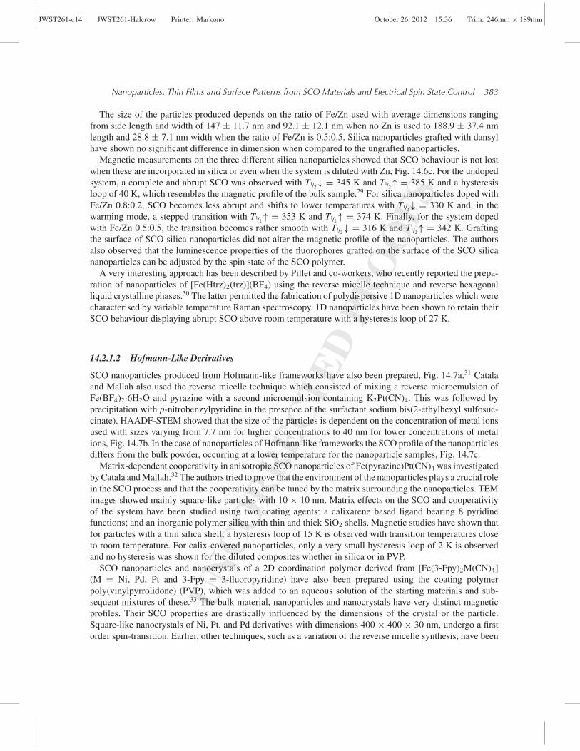
Nanoparticles, Thin Films and Surface Patterns from SCO Materials and Electrical Spin State Control 383
The size of the particles produced depends on the ratio of Fe/Zn used with average dimensions rangingfrom side length and width of 147 ± 11.7 nm and 92.1 ± 12.1 nm when no Zn is used to 188.9 ± 37.4 nmlength and 28.8 ± 7.1 nm width when the ratio of Fe/Zn is 0.5:0.5. Silica nanoparticles grafted with dansylhave shown no significant difference in dimension when compared to the ungrafted nanoparticles.
Magnetic measurements on the three different silica nanoparticles showed that SCO behaviour is not lostwhen these are incorporated in silica or even when the system is diluted with Zn, Fig. 14.6c. For the undopedsystem, a complete and abrupt SCO was observed with T1/2↓ = 345 K and T1/2↑ = 385 K and a hysteresisloop of 40 K, which resembles the magnetic profile of the bulk sample.29 For silica nanoparticles doped withFe/Zn 0.8:0.2, SCO becomes less abrupt and shifts to lower temperatures with T1/2↓ = 330 K and, in thewarming mode, a stepped transition with T1/2↑ = 353 K and T1/2↑ = 374 K. Finally, for the system dopedwith Fe/Zn 0.5:0.5, the transition becomes rather smooth with T1/2↓ = 316 K and T1/2↑ = 342 K. Graftingthe surface of SCO silica nanoparticles did not alter the magnetic profile of the nanoparticles. The authorsalso observed that the luminescence properties of the fluorophores grafted on the surface of the SCO silicananoparticles can be adjusted by the spin state of the SCO polymer.
A very interesting approach has been described by Pillet and co-workers, who recently reported the prepa-ration of nanoparticles of [Fe(Htrz)2(trz)](BF4) using the reverse micelle technique and reverse hexagonalliquid crystalline phases.30 The latter permitted the fabrication of polydispersive 1D nanoparticles which werecharacterised by variable temperature Raman spectroscopy. 1D nanoparticles have been shown to retain theirSCO behaviour displaying abrupt SCO above room temperature with a hysteresis loop of 27 K.
14.2.1.2 Hofmann-Like Derivatives
SCO nanoparticles produced from Hofmann-like frameworks have also been prepared, Fig. 14.7a.31 Catalaand Mallah also used the reverse micelle technique which consisted of mixing a reverse microemulsion ofFe(BF4)2·6H2O and pyrazine with a second microemulsion containing K2Pt(CN)4. This was followed byprecipitation with p-nitrobenzylpyridine in the presence of the surfactant sodium bis(2-ethylhexyl sulfosuc-cinate). HAADF-STEM showed that the size of the particles is dependent on the concentration of metal ionsused with sizes varying from 7.7 nm for higher concentrations to 40 nm for lower concentrations of metalions, Fig. 14.7b. In the case of nanoparticles of Hofmann-like frameworks the SCO profile of the nanoparticlesdiffers from the bulk powder, occurring at a lower temperature for the nanoparticle samples, Fig. 14.7c.
Matrix-dependent cooperativity in anisotropic SCO nanoparticles of Fe(pyrazine)Pt(CN)4 was investigatedby Catala and Mallah.32 The authors tried to prove that the environment of the nanoparticles plays a crucial rolein the SCO process and that the cooperativity can be tuned by the matrix surrounding the nanoparticles. TEMimages showed mainly square-like particles with 10 × 10 nm. Matrix effects on the SCO and cooperativityof the system have been studied using two coating agents: a calixarene based ligand bearing 8 pyridinefunctions; and an inorganic polymer silica with thin and thick SiO2 shells. Magnetic studies have shown thatfor particles with a thin silica shell, a hysteresis loop of 15 K is observed with transition temperatures closeto room temperature. For calix-covered nanoparticles, only a very small hysteresis loop of 2 K is observedand no hysteresis was shown for the diluted composites whether in silica or in PVP.
SCO nanoparticles and nanocrystals of a 2D coordination polymer derived from [Fe(3-Fpy)2M(CN)4](M = Ni, Pd, Pt and 3-Fpy = 3-fluoropyridine) have also been prepared using the coating polymerpoly(vinylpyrrolidone) (PVP), which was added to an aqueous solution of the starting materials and sub-sequent mixtures of these.33 The bulk material, nanoparticles and nanocrystals have very distinct magneticprofiles. Their SCO properties are drastically influenced by the dimensions of the crystal or the particle.Square-like nanocrystals of Ni, Pt, and Pd derivatives with dimensions 400 × 400 × 30 nm, undergo a firstorder spin-transition. Earlier, other techniques, such as a variation of the reverse micelle synthesis, have been

JWST261-c14 JWST261-Halcrow Printer: Markono October 26, 2012 15:36 Trim: 246mm × 189mm
UN
CO
RR
EC
TE
DPR
OO
FS
384 Spin-Crossover Materials
Fe
3.5
3
2.5
2
1.5
(a)
(c)
(b)
3
3.5Bulk
2
1
1 K/min0.5 K/min
0.2 K/min
4
2.5
2
1.5
1
0.5
0160 200 220 230 240 250 260 270 280 290 300240
T (K) T (K)280 320
Pt
403530252015105
50 nm
50 nm
0
200
150
100
50
0
5
5 10 15 20 25
6 7 8Range (nm)
Range (nm)
LengthWidth
Cou
ntC
ount
9 10 11
χ M T
(cm
3 K
mol
–1)
χ M T
(cm
3 K
mol
–1)
Figure 14.7 SCO nanostructures derived from Hoffmann-like objects: (a) representation of a 3D network ofFe(pyrazine){Pt(CN)4};8 (b) HAADF-STEM imaging and size distribution of particles (top, scale-bar 50 nm andbottom, scale-bar 50 nm); (c) magnetic plots of the objects obtained from two different concentrations: 1, 0.14mol L−1 and 2, 0.08 mol L−1 and bulk compound at a sweep rate of 1 K min−1 (left) and for 0.08 mol L−1 at threedifferent sweep rates (right). Reproduced from ref. 31. Copyright American Chemical Society.
used to give surfactant-free nanocrystals of [Fe(pz)Pt(CN)4] displaying size-dependent SCO with hystere-sis.34 Ultra-small monodisperse nanoparticles of the 3D SCO coordination polymer [Fe(pyrazine){Ni(CN)4}]obtained using the biopolymer chitosan as matrix were also reported with these particles retaining the coop-erative SCO behaviour.35
14.2.1.3 Pyridyl Derivatives
In 2010 Letard et al. investigated light-induced storage of information in nanoparticles.20 Nanoparticlesof [Fe(NCS)2(bpe)2] [bpe = 1,2-bis(4′-pyridyl)ethane] were prepared by the water-in-oil reverse micelletechnique, varying the amount of surfactant used, Fig. 14.8a. The reactant concentration was kept constant(0.05 M) and the mass of the nonionic polyoxyethylenic surfactant Ifralan D0205 was varied between[Fe(NCS)2(bpe)2]-25%, [Fe(NCS)2(bpe)2]-78%, [Fe(NCS)2(bpe)2]-85%. The consequences of particle sizereduction on light-induced and thermally induced SCO properties have been investigated. TEM images of

JWST261-c14 JWST261-Halcrow Printer: Markono October 26, 2012 15:36 Trim: 246mm × 189mm
UN
CO
RR
EC
TE
DPR
OO
FS
Nanoparticles, Thin Films and Surface Patterns from SCO Materials and Electrical Spin State Control 385
N
N
3.5
NCS
N
N
Fe
SCN
(c)
(a) (b)
(d)
3.0
T(LIESST) limit T(LIESST) limit
T(LIESST)
T1/2 shift
2.5
2.0
1.5
1.0
0.5
3.5
0.00
250
15
20
45
25 %
85 %201 nm
1 μm
01 2 3 4
10
20
30
50 75 100Size/ nm
Size/ μm
Par
ticle
sP
artic
les
–0.02
–0.04
–0.06
30 40 50 60
3.0
2.5
2.0
1.5
1.0
0.5
50
χ MT
/ cm
3 K
mol
–1
χ MT
/ cm
3 K
mol
–1
100T / K T / K
T / K
δχM
T /
δT150 50 100 150
Figure 14.8 Nanostructures from [Fe(NCS)2(bpe)2]: (a) structure of the compound used to produce nanoparti-cles; (b) (top) TEM images when 25% of surfactant was used (1–4 μm) and (bottom) when 85% of surfactant wasused (30–80 nm) with respective size distribution histograms; (c) magnetic plot for bulk [Fe(NCS)2(bpe)2] (�,T1/2
= 80/133 K), [Fe(NCS)2(bpe)2]-(25%-surfactant) (•, T1/2= 120 K), [Fe(NCS)2(bpe)2]-(78%-surfactant) (�,
T1/2= 110 K), [Fe(NCS)2(bpe)2]-(85%-surfactant) (�, T1/2
= 90 K); (d) magnetic plot for the thermally inducedand light-induced SCO of bulk [Fe(NCS)2(bpe)2] (macroscale particles, �), [Fe(NCS)2(bpe)2]-(25%-surfactant)(microscale particles, •) and [Fe(NCS)2(bpe)2]-(85%-surfactant) (nanoscale particles, �). Reproduced fromref. 20. Copyright Wiley/VCH.
the particles showed that their size is dependent on the amount of surfactant used. This is not surprising, asit had been previously shown. For lower amounts of surfactant the particles show rod-like features with sizesranging 1–4 μm. The size can be tuned down to 30–80 nm when 85% of surfactant is used, Fig. 14.8b.
Unlike the bulk material, the magnetic profile of the nanoparticles shows a slow one-step SCO for allamounts of surfactant used with T1/2 shifting to lower temperatures with increasing of the amount of surfactantused, Fig. 14.8c.
Light-induced excited spin state trapping effect (LIESST) was investigated by sample irradiation at 10 Kwith light working at λ = 530.2 nm. A light-induced excitation of the LS state to a metastable HS state wasobserved with the degree of conversion being dependent of the amount of surfactant used and consequentlythe size of the particles, Fig. 14.8d.

JWST261-c14 JWST261-Halcrow Printer: Markono October 26, 2012 15:36 Trim: 246mm × 189mm
UN
CO
RR
EC
TE
DPR
OO
FS
386 Spin-Crossover Materials
14.2.2 Sol-Gel Techniques
Alternative techniques to the reverse micelle method to prepare nanoparticles have been used by Boillot andco-workers to give access to thermo and photoswitchable SCO nanoparticles of an FeII complex trappedin transparent silica thin films.36 For that the authors used the sol-gel technique to fabricate nanoparticlesof discrete molecules based on [Fe((mepy)3tren)](PF6)2 ((mepy)3tren = tris(4-[(6-Me)-2-pyridyl]-3-aza-3-butenyl)amine), Fig. 14.9a. Nanoparticles were produced by mixing the crystalline solid in a previously agedsolution containing tetramethoxysilane (TMOS), dimethyldimethoxysilane (DMDMS), acetone and H2O.
Figure 14.9 Sol-gel technique to produce SCO nanoparticles: (a) molecular formula; (b) SEM images of[Fe((mepy)3tren)](PF6)2 nanoparticles embedded in silica thin films; (c) relative area variation of MLCT absorp-tion extracted from the Vis absorption data for 47 nm nanoparticles (�), 730 nm nanoparticles (�), precipitatedpowder (�) and crystalline powder (♦). The ratio (A10 – AT)/(A10 – A300) corresponds to the fraction of SCOcompounds in the HS state. Reproduced from ref. 36. Copyright Royal Society of Chemistry.

JWST261-c14 JWST261-Halcrow Printer: Markono October 26, 2012 15:36 Trim: 246mm × 189mm
UN
CO
RR
EC
TE
DPR
OO
FS
Nanoparticles, Thin Films and Surface Patterns from SCO Materials and Electrical Spin State Control 387
The obtained solution was then spin-coated on a glass slide where rapid evaporation of solvents quenchesthe growth of the particles in the silica thin film. Nanoparticles with different dimensions were obtaineddepending on the aging time of the sol, giving particles with dimensions of 730 (± 80), 300 (± 40), 72 (±16) to 47 (± 10) nm after 1 h, 2, 10 and 15 days, respectively, Fig. 14.9b.
Variable-temperature magnetic measurements were carried out both for the microcrystalline and the precip-itated powders. Although the nanoparticles show thermochromic behaviour, magnetic measurements on thinfilms of nanoparticles prepared by spin coating were inconclusive and the authors used variable temperatureUV-vis to probe the spin-transition in the nanoparticles, Fig. 14.9c. These have shown that the nanoparticleshave a magnetic behaviour very similar to that of the precipitated powders with T1/2 = 130 ± 5 K resulting indecreased cooperativity when compared to the crystalline sample. The authors also observed that the magneticprofile of the nanoparticles is size independent. Like the precipitated powders, the nanoparticles also showLIESST effect.
Faulmann et al. prepared nanoparticles of the SCO complex [Fe(Htrz)2(trz)](BF4) in xerogel transparentcomposite films.37 The dispersion and consecutive inclusion of the iron complex in a silica matrix preparedfrom TMOS or tetraethoxysilane (TEOS) afforded monoliths or films with a violet colour at room temperature,which turns white above 380 K. Particles with sizes ranging from 1 to 5 nm were imaged by TEM and theircomposition was confirm by EDX. Magnetic measurements showed that for films of nanoparticles in TMOSthe transition temperatures shifted towards higher temperatures with the hysteresis loops also getting narrowerwith the number of cycles like the bulk sample. The SCO of crushed thin films and as prepared thin films wasfurther confirmed by variable temperature Raman.
14.3 Thin Films
The engineering of SCO molecules towards processable memory devices is the main goal of applied SCOresearch. One of the most active routes pursued has been the deposition of such SCO active molecules onsurfaces. For this, several techniques have been used (Langmuir–Blodgett (LB) deposition, surface-assistedmolecular self-assembly, dip coating/drop casting, spin coating, complexes imbedded into matrixes), althoughonly a few of these have been successful. One technique which has been most used to fabricate thin films ofSCO active molecules is LB deposition. This and the other surface deposition techniques are reviewed below.
14.3.1 Langmuir–Blodgett Deposition
A single layer of molecules on a liquid–air interface is termed a Langmuir monolayer, and after transfer,is termed an LB film. It may be possible to transfer the monolayer to a surface if the surface substrate isimmersed into and emmersed carefully from the trough. More than one layer may be transferred by successiveimmersions and emersions, although this is not always possible. Upon LB layer formation on a surface threedifferent film architectures can result. Y-type multilayers are most common and X-type and Z-type films arerare.38
The first attempts to form a SCO LB film were made by Kahn and Ruaudel-Texier using an amphiphilicderivative of the well-known [Fe(phen)2(SCN)2] complex, Fig. 14.10a.39, 40
The LB film of this complex was transferred onto calcium fluoride and quartz substrates accomplishing asuccessful transfer of up to 200 layers, Fig. 14.10b. The type of film was inconclusive and of type X or Z andhas been shown by variable temperature IR to exhibit thermal SCO with T1/2 = 260 K and a hysteresis loopof ca. 4 K, Fig. 14.10c.40

JWST261-c14 JWST261-Halcrow Printer: Markono October 26, 2012 15:36 Trim: 246mm × 189mm
UN
CO
RR
EC
TE
DPR
OO
FS
388 Spin-Crossover Materials
1
0.5x
0100 150 200 250 300
T / K
Figure 14.10 Production of SCO LB films: (a) molecular structure of [Fe(phen)2(SCN)2] derivative;39, 40 (b)Langmuir–Blodgett deposition on a surface starting with a hydrophobic substrate;38 (c) temperature dependenceof molar fraction of HS species in both cooling and warming modes based on vibrational modes changes followedby IR. Reproduced from refs 38 and 40. Copyright American Chemical Society and the Royal Society of Chemistry.
Later in 1998, Mingotaud and co-workers studied the formation of Langmuir and LB films on a deriva-tised [Fe(bpy)2(SCN)2] with bpy = 2,2′-bipyridine. Langmuir films were found to be very unstable whenformed at the air–water interface. The problem was overcome when a mixed liquid phase was used. Thestability of the Langmuir films increased considerably when a water:DMF mixture was used as liquidphase, and a further increase in stability was achieved when a mixture of water:DMF:KNCS was used.Y-type LB multi-layered films were transferred onto a calcium fluoride substrate and characterised byvariable temperature IR spectroscopy. The SCO showed a quite distinctive profile if the magnetic mea-surements on the film were performed below 340 K (gradual and incomplete with T1/2 = 292 ± 7 K), orby heating above 340 K. The latter transition is more abrupt and complete than the former cycle, but isirreversible.41, 42
A third Fe(II) LB film was obtained using a small variation of the bpy ligand described in the previousexample. Langmuir films obtained using an aqueous solution of KSCN as subphase and complexes with aligand derived from bpy with R groups (CH2)12-(CF2)5-CH3 and Me were transferred onto a Mylar substrate.

JWST261-c14 JWST261-Halcrow Printer: Markono October 26, 2012 15:36 Trim: 246mm × 189mm
UN
CO
RR
EC
TE
DPR
OO
FS
Nanoparticles, Thin Films and Surface Patterns from SCO Materials and Electrical Spin State Control 389
Multilayered (>1200 layers) LB films were also shown to display thermal SCO with hysteresis. Furthermore,the complex was shown to present the Light Induced Excited Spin State Trapping (LIESST) effect, showinga more efficient LIESST process when compared to the powdered sample.43–45
Armand et al. used the same approach to fabricate LB films of the alkylated coordination polymer[Fe(C18trz)3]X2 (X = perchlorate, triflate, tosylate).46 The attempts were not successful due to the instabilityof the complexes at the air–water interface.46 This is not surprising, as LB films of SCO complexes have oftenexhibited assembly problems, due to chemical instability of the iron complexes at the air–water interface andconsequent hydrolysis of the coordination bonds, or oxidation of the metal centres. Attempts to minimisethe hydrolysis have included the use of a DMF-water mixture as the subphase instead of pure water, and theuse of semifluorinated chains to avoid organic solvents. A very interesting approach by Roubeau towardsstabilisation of the Langmuir films at the air–water interface was the use of aqueous solutions of metalsalts as a subphase. Solutions of Co(NO3)2, Ni(NO3)2 and Zn(NO3)2 all proved successful. These saltsolutions permitted closer packing and formation of stable Langmuir monolayers, which were suitable forthe fabrication of up to 1100 LB multilayers.47 When this technique was applied to SCO complexes, partialthermal SCO in [Fe(C18trz)3](NO3)2 polymers was detected by magnetic measurements of 400–1100 LBmultilayers deposited from a subphase containing Fe(NO3)2. For subphases containing other metal salts, noSCO was observed in LB films of [Fe(C18trz)3](NO3)2 polymers.47, 48
A different and more recent approach was developed by Kurth and co-workers where they fabricatedLB multilayers using a polyelectrolyte-amphiphile complex (PAC). PAC were formed by self-assembly ofa metallo-supramolecular polyelectrolyte (MEPE) based on the ditopic bis-terpyridine 1,4-bis(2,2′:6′,2′′-terpyridine-4′-yl)benzene and dihexadecyl phosphate (DHP). LB films of PAC with 11–15 layers have beenprepared and structurally characterised.49, 50 Unlike the bulk material, the SCO of the PAC LB films isincomplete but reversible.51, 52
Brooker and Albrecht have used the LB technique to prepare Langmuir films of discrete Fe(II) complexeswhich have been shown to be very unstable.53 More recently they have shown that functionalisation ofthe 3,5-di(2-pyridyl)-4H-1,2,4-triazole (dpt) ligand with a C16 aliphatic chain forms a SCO Fe(II) complex,[Fe(C16dpt)2(NCS)2], with T1/2 = 290 K. This Fe(II) complex was also found to form stable Langmuirmonolayers at the air–water interface but no attempts to form LB films were reported.54
Recently Albrecht and Morgan extrapolated these same principles to Fe(III), Co(III) and Mn(III)amphiphiles. The authors reported the formation of stable Langmuir films with redox stable Fe(III) amphiphiliccomplexes derived from [Fe(sal)2trien]+ (sal = salicylaldehyde, trien = triethylenetetramine), Fig. 14.11.55
Although these complexes do not show SCO in the solid state, the longer C18 complex shows an abruptSCO in solution.56 Complexes with alkyl chains with a length ranging from six to eighteen carbons weretested and their ability to form Langmuir films was investigated. The authors observed that only the longerC18 complexes formed suitable Langmuir films for surface transfer. The transfer process was limited tofour layers and the spectroscopic characterisation was inconclusive with respect to occurrence of LBfilm SCO.
The extension of similar amphiphilic systems to Mn(III) was accomplished by functionalisation of a ligandknow to promote SCO with Mn(III) ions.57 It was observed that in these ions the SCO is sensitive to thelength and position of the alkyl chains with all spin transitions gentle and incomplete. It was also observedthat the complexes with longer alkyl chains (C12 and C18) formed densely packed Langmuir monolayerswith intermolecular contacts occurring at earlier stages of compression for the C18-functionalised complexes.Stability tests using the C18-functionalised complexes have shown that only the complex bearing cisoidalkyl chains were able to form reasonably stable Langmuir films over extended periods of time. Attempts totransfer Langmuir films were not successful resulting in only partial transfer due to significant desorption ofthe material during downstrokes.

JWST261-c14 JWST261-Halcrow Printer: Markono October 26, 2012 15:36 Trim: 246mm × 189mm
UN
CO
RR
EC
TE
DPR
OO
FS
390 Spin-Crossover Materials
Figure 14.11 Production of [Fe(R-sal)2trien]+ LB films: (a) C18 amphiphilic compound used to fabricate LB films;(b) Langmuir layers of [Fe(C18-sal)2trien]NO3, transferred onto glass support; (c) representation of type of LB filmformed. Reproduced from ref. 55. Copyright Royal Society of Chemistry.
14.3.2 Surface-Assisted Molecular Self-assembly
A more successful approach than the LB technique is the multilayer sequential assembly (MSA) technique.This technique consists of the deposition/assembly of sequential layers by coordination bonds.58, 59 Thus,Bousseksou and co-workers have prepared thin films with multilayers of the Hofmann-type SCO compound,[Fe(pz)M(CN)4] where M = Ni, Pd, or Pt using the MSA method by epitaxial growth on gold surfaces,Fig. 14.12a.60
The thin films formed by MSA retained the SCO characteristic of the bulk material. The SCO in themultilayers shows a 25 K wide hysteresis window centred around 310 K but the transition is less abrupt thanin the powdered sample, Fig. 14.12b and 14.12c.
14.3.3 Diverse Techniques
Spin coating is a widely used and very versatile technique with several advantages. It is simple, cost effective,produces a low amount of waste, is rapid and highly reproducible and produces homogeneous films on asubstrate. Spin coating is widely used in fabrication of inorganic nanostructure self-assemblies but majordrawbacks are the limitation by the solvent and the lack of order after evaporation of the solvent.61

JWST261-c14 JWST261-Halcrow Printer: Markono October 26, 2012 15:36 Trim: 246mm × 189mm
UN
CO
RR
EC
TE
DPR
OO
FS
Nanoparticles, Thin Films and Surface Patterns from SCO Materials and Electrical Spin State Control 391
(a)
(b) (c)
1.0
0.5
0.0
1.0
0.5
0.0
250250 300 3500
2
4
300 350
T /KT /K
I(norm)χMT/
cm3 mol–1 k: I(norm)
1) Fe2+
3)1), 2), 3), etc
Fe
Fe
L2) L = Pt(CN)4
2+
Au
N
N
N N N
N N N
NN
Figure 14.12 Surface confined Hofmann-type SCO assemblies: (a) representation of SCO thin film formationof [Fe(pz)Pt(CN)4].; (b) temperature dependence of the χmT product (×) and the normalised Raman intensityratio (�) for [Fe(pyrazine)Pt(CN)4] powder on cooling and heating modes. (c) Temperature dependence of thenormalised Raman intensity ratio for [Fe(pyrazine)Pt(CN)4] powder (�) and film (◦) samples on cooling andheating modes. Reproduced from ref. 60. Copyright Wiley/VCH.
The spin coating technique has also been applied to SCO complexes and the first report on attemptsto fabricate a SCO thin-film by this technique was by Matsuda and Tajima.62 [Fe(dpp)2](BF4)2 (dpp =2,6-di(pyrazolyl)pyridine) was chosen, which shows an abrupt spin-transition centred at 259 K with a 3 Khysteresis loop in the solid state, and a gradual transition in acetone solution. Smooth 30 nm thick films wereprepared on a glass substrate from a saturated acetonitrile solution of the complex. The SCO property of theprepared film was investigated by variable temperature UV-vis spectroscopy and SQUID magnetometry andshows that these films show an abrupt and reversible SCO at ca. 260 K. Conductivity measurements performedon films sandwiched by indium-thin oxide (ITO) and aluminium over the SCO transition temperature haveshown that there is a small change in resistivity with change in spin state.
As a follow up, the authors utilised the same SCO molecule and spin coating method to embed a SCO com-plex into a light-emitting layer of an EL device of chlorophyll a. By doping chlorophyll a with a SCO complexthe authors achieved a drastic change of the EL intensity accompanying the SCO of [Fe(dpp)2](BF4)2.63
A different approach has been developed by Kojima and co-workers, in which a Nafion film was dopedwith the SCO complex [Fe(Htrz)3].64 The properties of thermal spin-transition as well as photoinduced SCOon the film have been reported. The Fe(II)-doped Nafion film was prepared by immersion of a Nafion film inan aqueous solution of an iron salt followed by immersion in a methanolic solution of 1,2,4-1H-triazole. Themagnetic profile of the film, which shows a SCO around T = 250 K with a small hysteresis loop of about 5 K,
JWST261-c14 JWST261-Halcrow Printer: Markono October 26, 2012 15:36 Trim: 246mm × 189mm
UN
CO
RR
EC
TE
DPR
OO
FS
392 Spin-Crossover Materials
has been characterised in a separate report by Kojima et al. published around the same time.65 PhotoinducedSCO has been observed at low temperatures with an efficiency of conversion of 70% and decay dynamicssuggesting that stochastic nucleation dominates the relaxation process. Later, the SCO behaviour of the filmwas further confirmed by Moßbauer spectroscopy.66 The P-T phase diagram for the photoexcited steady stateof the Nafion-[Fe(Htrz)3] film has also been determined67 and the same investigations have been extended tothe parent system [Fe(NH2-trz)3]-Nafion. The prepared film shows a smoother SCO centred at 198 K.68 Tofinalise the extensive work developed on these Nafion-[Fe(R-trz)3] films, Kojima and co-workers reported in2005 the preparation of transparent SCO Nafion-[Fe(Htrz)3] film showing thermochromic behaviour changingfrom transparent (HS) to purple (LS).69
Recently, Kojima et al. demonstrated that the same principle can be applied to other SCO systems.70 Theelected candidate between the broad range of examples of Fe(II) SCO complexes has been [FeII(diAMsar)]2+
(diAMsar = 1,8-diaminosarcophagine) where, as in the powdered samples, [FeII(diAMsar)]-Nafion filmsshow a thermochromic dependence with the pH which is correlated with the SCO property of either thepowder or the films.
Boillot reported poly(methyl methacrylate) (PMMA) polymeric films doped with the Fe(II) SCO complex[Fe(stpy)4(NCSe)2] (stpy = styrylpyridine).71 Films were prepared from a mixture of PMMA with increasingamounts (2–20 wt %) of the [Fe(stpy)4(NCSe)2] complex. Transparent and semi-rigid PMMA doped thinfilms showed SCO at T = 135 ± 25 K, which is comparable to that of the crystalline sample (T1/2 = 163 K).
Finally, vacuum deposition has been used to produce thin films of SCO complexes. This method can onlybe applied to molecules that are stable to decomposition under the ultra-high vacuum deposition conditionsand has several advantages: it avoids dilution of the complexes embedded in a matrix; it allows exact controlof the thickness of the films; and it can be applied to patterning techniques. Despite all these advantages,until now only two examples have been reported.
The first example was reported by Shi and Beaurepaire.72 The authors described high-quality thin films of[Fe(phen)2(SCN)2] deposited on silicon or glass substrates by evaporation under high vacuum. However, thefilm morphology was shown to be sensitive to air and became coarse under ambient conditions. The composi-tion of the film and confirmation of its integrity was demonstrated by X-ray photoelectron spectroscopy (XPS)on a 280 nm thick [Fe(phen)2(SCN)2] film. Optical transmission measurements were used to investigate theelectronic structure of the films and the authors claimed that for films ranging from 7 to 530 nm the electronicstructure of these remains practically unaltered. Moreover the magnetic profile of a 280 nm thick film wascharacterised by SQUID magnetometer measurements, showing that thicker films retain the SCO propertywith T1/2 = 175 K.
A more recent report by Quandt and Tuczek exploits the formation of thin films by high vacuum depositionmethod of SCO complexes exhibiting a LIESST effect.73 The complexes studied were [Fe(H2Bpz)2(phen)](H2Bpz = bis(pyrazolyl)borate) and [Fe(H2Bpz)2(bipy)] (bipy = 2,2′-bipyridine). In the solid state,[Fe(H2Bpz)2(bipy)] shows a SCO centred at T1/2 = 159.5 K and a TLIESST = 52 K, while [Fe(H2Bpz)2(phen)]shows a SCO centred at T1/2↑ = 165.0 K, T1/2↓ = 162.7 K and a TLIESST = 44 K.7 Thin films were depositedon ITO-coated glass or polymer tape and the thicknesses of the films were determined by a profilometer, theirsurface quality was investigated 4by AFM. A thin film of [Fe(H2Bpz)2(phen)] was prepared with a thicknessof 480 nm and a rms roughness of 3.15 nm and a second thin film of [Fe(H2Bpz)2(bipy)] was also preparedwith a thickness of 410 nm and rms roughness of 3.7 nm. The thermal and light-induced spin-transitions ofthe thin films were monitored by UV-vis absorption spectroscopy.
From the UV-vis spectra, the authors deduced the spin-transition temperatures for each of the thin films.For thin films of [Fe(H2Bpz)2(phen)] the T1/2 = 155 K (± 1 K) which is comparable with the transitiontemperature of the solid sample (T1/2↑ = 165.0 K, T1/2↓ = 162.7 K). For thin films of [Fe(H2Bpz)2(bipy)] theT1/2 = 166 K (± 1 K) which is also close to the transition temperature of the solid sample (T1/2 = 159.5 K).

JWST261-c14 JWST261-Halcrow Printer: Markono October 26, 2012 15:36 Trim: 246mm × 189mm
UN
CO
RR
EC
TE
DPR
OO
FS
Nanoparticles, Thin Films and Surface Patterns from SCO Materials and Electrical Spin State Control 393
LIESST-effect studies on thin films of both complexes were performed by irradiation of the film with a 525 nmwavelength light. For thin films of [Fe(H2Bpz)2(phen)], TLIESST = 44 K with an efficiency of conversion tometastable HS of 83%. For films of [Fe(H2Bpz)2(bipy)], TLIESST = 51 K with an efficiency of conversion tometastable HS of 85%.
14.4 Surface Patterns
The search for practical applications within the field of SCO either by insertion of active molecules intodevices or by constructing devices out of SCO materials have brought together chemists and materialscientists. In a different but complementary approach to those described above, Ruben and Cavallini, Molnarand Bousseksou, and finally Vieu, have investigated the possibility of depositing SCO compounds on surfacesthrough patterning techniques.
14.4.1 Surface Patterns of Spin-Crossover
Ruben et al. used discrete molecules to reproduce the pattern of a CD through lithographic techniques. For thisthe authors considered that the information generated in a SCO switching event occurs within the nanometricregime, thus the interfacing of the molecular switching units with the microscaled device environment wouldbe of crucial importance. Considering this, the elected candidate for patterning was the neutral SCO complexcis-bis(thiocyanato)bis(1,10-phenanthroline)iron(II) which shows a thermal spin-transition centred at 176K,Fig. 14.13a.75, 76
The techniques used to deposit the SCO molecules on surfaces were Micro Injection Molding in Capil-laries (MIMIC) to fabricate micrometric stripes and Lithographically Controlled Wetting (LCW) to patternsubmicrometric and nanostructures, Fig. 14.13b. It has been observed that the SCO compound crystallisesinto micro- and nanowires or dots. Such patterns were characterised by AFM, polarised optical microscopy,grazing incidence X-ray diffraction (GIXD) and Raman spectroscopy.
AFM studies of structures of the SCO compound printed by MIMIC on silicon revealed the formationof strip-like structures (micrometric stripes) 1 μm in width, similar to the features of a stamp, Fig. 14.13c(left). Optical images obtained by polarised microscopy indicated behaviour typical for optically anisotropicmaterials exhibiting birefringence, Fig. 14.13c (centre and right). In particular, the microstripes appearedhomogeneously coloured indicating that their thickness is almost constant over the entire stripe but changesbetween different stripes. Based on these observations it was deduced that confined deposition by MIMICinduced a coherent, long-range order along the length of the stripes. To obtain features in the nanometreregime the LCW technique was used. Structures with a resolution of approximately 160 nm were achieved,by estimation of the full width at half-maximum; below this limit the stamp features were not perfectlyreplicated.
The structure of nanopatterned films was investigated by GIXD. Azimuthal scans for both 010 and 001reflections, forbidden for the original structure, were measured, indicating that the molecular arrangement(with loss of symmetry elements) is slightly different from that in the bulk, Fig. 14.13d. Finally, the authorsaimed to pattern SCO representing information storage. For this, films of [Fe(phen)2(SCN)2] were mouldedby LCW into a logic pattern replicating a recorded compact disk. The imaging of the patterned film bydark-field optical microscopy and AFM revealed an ordered array of crystallites of [Fe(phen)2(SCN)2]. TheSCO was probed by variable temperature Raman performed on freshly prepared films, Fig. 14.13e. Freshlyprepared films exhibited Raman spectra very similar to those of the powder retaining the SCO property.75
This property was found to be unstable over time due to aging of the micro/nano architectures.

JWST261-c14 JWST261-Halcrow Printer: Markono October 26, 2012 15:36 Trim: 246mm × 189mm
UN
CO
RR
EC
TE
DPR
OO
FS
394 Spin-Crossover Materials
(a)
N
N
N
N
(c)
(e)(d)
(010)
(001)300 K
1420
2070
1455
2115
200018001600140012001000800
68.4 68.5 68.6 68.7
2θ / °
Raman shift / cm–1
Inte
nsity
Inte
nsity
77 K
1449
2 μm 3 μm
(a) (b) (c)
(b)
NCS
NCS
Fe
1
1
2
2
33 4
Figure 14.13 Stamping of SCO nanostructures: (a) molecular structure of compound used to create patterns;(b) representations of the processes used to patterning SCO molecules; (c) microstripes of [Fe(phen)2(SCN)2]fabricated by MIMIC on a silicon surface: (left) AFM topography (z scale is 50 nm), (middle) optical micrographsrecorded with unpolarised light, (right) micrographs recorded with crossed polars oriented along the axes ofthe image; (d) GIXD azimuthal scan for the (010) of microstripes printed by MIMIC and respective top viewof the 3D structure of [Fe(phen)2(SCN)2] in the microstripes, as oriented in one domain. The red arrow indicatesthe orientation of the microstripes; (e) Raman spectra of freshly prepared films, at 300 and 77 K with SCOevident from the vibrational modes at 1449, 1420 and 2070 cm−1. Reproduced from refs 75 and 76. CopyrightWiley/VCH and the American Chemical Society.
More recently, the same authors built on the experience obtained with the previous system, to fabricatethin deposits and patterns of a room-temperature-switchable 1D SCO compound which crystallises to forman infinite 1-D chain exhibiting a SCO at T = 286 K.77 With the aim of controlling the spatial distribution andthe morphology of thin deposits, the authors used the LCW technique. The thin films and patterns preparedwere characterised by AFM, polarised optical microscopy, XRD and Raman spectroscopy. Patterns of the

JWST261-c14 JWST261-Halcrow Printer: Markono October 26, 2012 15:36 Trim: 246mm × 189mm
UN
CO
RR
EC
TE
DPR
OO
FS
Nanoparticles, Thin Films and Surface Patterns from SCO Materials and Electrical Spin State Control 395
SCO compound prepared by LCW revealed the formation of stripe-like structures of 1 μm width, observedby optical microscopy and AFM.
It was found after a detailed AFM analysis of the morphology of the stripes, that the patterns show thateach stripe is formed by rod-like crystallites. The SCO properties of these stripes were investigated by Ramanspectroscopy. Raman experiments showed that the compound retains its SCO nature when the solvent shrinksslowly; interestingly, when fast shrinkage was employed, the thin deposit lost the ability to undergo SCO.
In 2007, Bousseksou and Molnar reported on a process for nano and microscale assembly of the 3-D SCOcoordination polymer Fe(pyrazine)[Pt(CN)4] which displays a very strong cooperative spin-transition witha ca. 25 K wide hysteresis loop centred around room-temperature.78 These nano and microscale assemblieswere produced using a combination of top-down (lift-off) and bottom-up (MSA) methods, employing a gold-coated silicon surface covered by a conventional polymethylmethacrylate (PMMA) EBL resist. Square-shapedpatterns of different sizes and densities were written by a focused electron beam. After resist development,the substrates were dipped into a solution of 4,4′-azopyridine to prepare an anchoring layer for the thin film.Patterns of sizes ranging from 50 nm to 2 μm were created and imaged by SEM.
Limiting factors present during the process were desorption and re-adsorption accompanied by the forma-tion of crystallites which originated 3-D crystallites with substantial roughness at large thickness. To probethe spin state of the micro and nanopatterned assemblies, Raman spectroscopy was used on patterns of 2 μm,500 nm and 200 nm. Raman spectra of the larger nanopatterns allowed the identification of a thermal spin-transition where the vibrational mode at 1232 cm−1 changes dramatically in relative intensity. For smallersizes the identification of the change in relative intensities was much more difficult, with arrays of 200 nmnanopatterns giving Raman spectra at both temperatures that were very similar, but sufficient for the authorsto claim a spin-transition at the nanometric regime.
Later, Bousseksou produced 3-D coordination polymers derived from [FeII(azpy)(MII(CN)4)]·nH2O(azpy = 4,4′-azopyridine; M = Ni, Pd, and Pt), to fabricate nanopatterned thin films on gold substrates.Micro- and nanometric patterns were obtained using a PMMA mask as a physical barrier for the assembly ofthe multilayers on the substrate, Fig. 14.14a, b and c.79 The authors have characterised the SCO characteristicof both bulk materials and nanopatterned materials by Raman and concluded that nanopatterned thin filmson gold substrates retained their SCO characteristics, Fig. 14.14d and e.
Recently, Bousseksou and Salmon used the previously described methods to fabricate micro- and nanopart-terned thin layers of the compound [Fe(bpac)(M(CN)4)] (bpac = bis(4-pyridyl)acetylene; M = Ni, Pd, and Pt)with pattern sizes of 2000, 200 and 30 nm.80 The authors investigated the uptake of guest solvent moleculesby the porous patterns and observed that the SCO behaviour is different and reversible when inclusion ofpyridine occurred.
Finally, Vieu et al. reported their work on soft lithographic patterning of SCO nanoparticles using micro-transfer moulding (μTM) to pattern [Fe(NH2trz)](tos)2 (tos = tosylate, NH2trz = 4-amino-1,2,4-triazole).This SCO compound is known to exhibit a relatively abrupt thermal transition between the HS and LS formsaround room temperature. To form such patterns of SCO nanoparticles, a drop of the nanoparticle suspensionwas placed on the patterned surface of a PDMS stamp and the excess solution was removed by a stream ofnitrogen until the PDMS stamp was completely dry. Finally, the filled stamp was placed in contact with asubstrate and peeled away.81 Using this method the authors fabricated micrometric features of 5 μm meshesthat were perfectly ordered with no defects. The resolution limit of the patterned stripes was further movedinto the nanometer regime by using μTM. Structures with a resolution of approximately 300 nm could beachieved with good thickness homogeneity and very few defects. Despite the difficulties in assigning the SCOtransition of the patterned nanoparticles because the spectrum of the microstructures is dominated by thestrong Raman scattering of the NaAOT surfactant used during the fabrication process of the nanoparticles, theauthors claimed to have prepared micro- and nanopatterns of SCO nanoparticles retaining their spin switchingcharacteristic after fabrication of such materials.

JWST261-c14 JWST261-Halcrow Printer: Markono October 26, 2012 15:36 Trim: 246mm × 189mm
UN
CO
RR
EC
TE
DPR
OO
FS
396 Spin-Crossover Materials
Figure 14.14 Templating of SCO nanostructures: (a) 3-D coordination polymer of [FeII(azpy)(MII(CN)4)]·nH2O;(b) scheme of deposition of 3-D coordination polymer on gold surface; (c) SEM images of patterns ofFe(azpy)[Pd(CN)4] obtained following 10 deposition cycles for different shapes with distinct sizes between2 μm and 30 nm; (d) variable temperature Raman spectra of bulk material indicating SCO; (e) variable temper-ature Raman spectra of nanopatterns indicating SCO. Reproduced from ref. 79. Copyright American ChemicalSociety.
14.5 Electrical Spin State Control
Fabrication of typical data storage devices is performed using a top-down approach where the size of discretemagnetic domains is constantly reduced in dimensions.82 The size of discrete magnetic domains can bereduced until the super paramagnetic limit is reached, where ambient temperature is sufficient to invert themagnetisation of such domains leading to highly unstable devices.83, 84 To overcome this problem scientistshave been developing strategies using diverse and imaginative solutions such as antiferromagnetic couplingmedia recording,85 perpendicular recording86 and lithographically patterned media recording,87 while theassembly of magnetic molecules into nanowires has been reported producing a huge advance in the area ofinformation storage.88, 89
In a complementary bottom-up approach, chemists have applied supramolecular principles to fabricatemolecular machines, motors and switches, and devices for information storage and processing represent aparticularly attractive field in this research area. For example, reversible data storage may become possible onthe nanoscale by imprinting information via a change of magnetisation. Reversibility of this process requiresmaterials with variable magnetisation states that can be addressed selectively and without perturbation of

JWST261-c14 JWST261-Halcrow Printer: Markono October 26, 2012 15:36 Trim: 246mm × 189mm
UN
CO
RR
EC
TE
DPR
OO
FS
Nanoparticles, Thin Films and Surface Patterns from SCO Materials and Electrical Spin State Control 397
Figure 14.15 Electrical properties of a SCO film: current–voltage characteristics for a 240 nm thick film of[Fe(phen)2(SCN)2] evaporated on a silicon substrate at 300 K and linear fits to the data. Reproduced fromref. 72. Copyright American Institute of Physics.
the entire environment. Research has been developed where bistable magnetic states are addressed mainlyby application of temperature or light. For electronic purposes, it is desirable to apply an electric field toswitch between two states which would permit fabrication of molecular devices where the magnetic statesare controlled electrically.
Studies on attempts to electrically control the spin states on SCO complexes are quite recent and thefirst studies on devices have been reported by Shi and Beaurepaire, Fig. 14.15.72 A device was constructedusing a 240 nm thick film of [Fe(phen)2(SCN)2] evaporated on a silicon substrate with gold electrodes. Thecurrent–voltage (I-V) characteristics at room temperature of the device were determined, and at low voltagethe ln(I)-ln(V) characteristic is linear with a slope of 1.17 suggesting Ohmic conduction. Above 1.4 V, theln(I)-ln(V) characteristic remained linear but with a slope of 2.04, indicating a space charge-limited current(SCLC) regime. The authors extracted a mobility of 6.53 × 10⁻⁶ cm2/Vs in the space charge-limited regime,comparable to that found in typical small organic molecules.
Developments of Coronado’s work with SCO nanoparticles reported in 2007 have been recently achieved,where Coronado and van der Zant described devices built from a single SCO nanoparticle.90 Nanoparticlesbased on a core of the Fe(II) coordination polymer [Fe(trz)3](BF4)2 (trz = triazole) and a surfactant shellaround 11 nm in diameter were placed between two nanometer-spaced electrodes. Such particles have beencharacterised in detail and show a cooperative spin-transition from Fe(II) low spin, S = 0, to high spin,S = 2, exhibiting a thermal hysteresis loop above room temperature with a width of ca. 40 K.21, 24
Current–voltage (I–V) experiments at 10 K led to the observation that for the 100-nm-wide electrode,equidistant step-like features and peaks in the corresponding derivative
(dI/dV), are reminiscent of a Coulomb staircase. Based on these observations, the authors concluded thatthe transport mechanism is due to sequential single-electron tunnelling through an asymmetric double-barrierjunction. The nanoparticle core is isolated from the electrodes by tunnel barriers defined by the surfactantlayer where, electrons first tunnel onto the particle and remain there for some time before tunnelling off again.Coulomb steps are equidistant and therefore indicate that transport occurs through a single particle.
The current–voltage characteristics of the devices measured between 300–400 K show that there was achange in conductance in the temperature region of the SCO. Moreover, a hysteresis loop was observedin the current–voltage characteristic of the devices, although this was only observed in 30% of the devices

JWST261-c14 JWST261-Halcrow Printer: Markono October 26, 2012 15:36 Trim: 246mm × 189mm
UN
CO
RR
EC
TE
DPR
OO
FS
398 Spin-Crossover Materials
W = 1μm
W = 1μm
T = 10 K
T = 10 K
W = 100 nm
I (nA
)
I (nA
)
I (nA
)V
(V
)
I/V =
0.04 nS
0.02 nS
T = 340 K
(a)
0.3
0.2
0.1
0.0
1.0
0.0
0.0
0.4
0.03
0.02
0.01
0.000.0
1 2 3 4 5 6Cycle
0.4V (V) V (V)
0.8 0.0 0.2 0.4
(b)
(c)
Figure 14.16 Device of [Fe(trz)3](BF4)2SCO nanoparticles: (a) Current–voltage characteristics of a 1-μm-wideelectrode device at low temperature; (b) current–voltage characteristic of a 100-nm-wide electrode device at340 K. The conductance (I/V) at 0.4 V coincides with the values observed in the thermal hysteresis of the samedevice, showing that the bistability can be probed with an applied voltage; (c) repetitive cycling of the voltagebetween 0 and 1 V at low temperature (10 K) of the device. Reproduced from ref. 90. Copyright Wiley/VCH.
tested. The authors found that by keeping the temperature constant but changing the applied bias voltage, atransition between the low- and the high-conductance state occurs, being the effect more pronounced at lowtemperature, Fig. 14.16.
The device whose conductance is represented in Fig. 14.16a was cycled 6 times and it was observed that thelifetime of the high-conductance states varies. Factors such as electric field polarisation, intersystem crossingthrough excited states and local resistive heating are possible explanations for this observation.
More recently, Ruben and van der Zant reported on the electrical control of SCO in a single molecule.91
The approach used by the authors was different from that previously reported, where SCO is triggered bycharging the molecule with two electrons. This was predicted by theoretical calculations and confirmedexperimentally by a split of zero bias (Kondo) resonance in the current–voltage characteristics. Theoreticalcalculations suggest that the spin-transition should manifest itself in an electron transport experiment by thespecific structure of its magnetic excitations and experiments were carried out with a three terminal deviceand the low-energy excitation probed by inelastic tunnelling spectroscopy. Transport experiments revealed adouble-quantum-dot behaviour in combination with a split Kondo peak, Fig. 14.17. This experiment opensthe realm of active spin state modulation in a molecule; the smallest possible SCO switching unit.
Finally, Bousseksou reports on electrical properties and the nonvolatile memory effect of a SCO complex.92
The authors built a nonvolatile memory device based on changes of the dielectric permittivity allowing theinformation to be stored in the high- and low-capacitance states. The compound elected for these studieswas [Fe(HB(pz)3)2] where HB(pz)3 = hydrotris(1-pyrazolyl)borate. This compound is known to undergo athermal spin transition in the 300–450 K temperature range with the first heating cycle completely differentfrom successive thermal cycles. Such a difference has been attributed to a crystallographic transformation.

JWST261-c14 JWST261-Halcrow Printer: Markono October 26, 2012 15:36 Trim: 246mm × 189mm
UN
CO
RR
EC
TE
DPR
OO
FS
Nanoparticles, Thin Films and Surface Patterns from SCO Materials and Electrical Spin State Control 399
(a)
(b) (c)
20
ST
I II III
8×10⁻⁴(nS)
6
4
2
0
–2
–4
10
0
–10
–200
S
S
T
TVg
Vb
0.2 0.4 0.6 0.8 1 1.2Vg (V)
Vb
(mV
)
Figure 14.17 (a) Simulation of the differential conductance vs. source-drain (Vb) and gate (Vg) voltages cal-culated for T = 4.2 K; (b) schematic representation of the double-dot system. T: transfer dot, S: spectator dot;(c) schematic representation of molecule-electrode contacts realising the double-dot system. Reproduced fromref. 91. Copyright American Physical Society.
Thin films of the compound, of ca. 200 nm thickness, were deposited on gold interdigitated microelectrodesby thermal evaporation and the composition of the films was confirmed by Raman spectroscopy.
The resulting thin film had a densely covered surface with a granular morphology composed of nanocrystals,and was used for AC conductivity measurements as a function of frequency and temperature. Isothermalfrequency measurements revealed a change in conductivity with a frequency dependence more pronouncedthan in the powdered sample, which the authors attributed to a higher degree of disorder of the thin films.I-V measurements were performed on a thin film, at room temperature, before and after heating the film to408 K, showing that these differ considerably. A complementary experiment was carried out by changing theapplied electric bias from 1 to 10 V. An increase in current was observed upon changing the applied bias from1 to 2 V, but over time the current drops to low conductivity values. A further increase in voltage showed asmall increase in current, which remained in the low conductivity region. Based on these observations theauthors claimed the construction of a nonvolatile read-only memory (ROM) using a SCO compound.
14.6 Conclusion
SCO is a fascinating interdisciplinary area of research which has attracted experimentalists and theoreticiansfrom chemistry, physics, materials science and engineering. SCO research emerged 80 years ago and a longand impressive literature on SCO has been developed with the discovery of several new examples of SCOcompounds, the explanation of different types of SCO profiles and the modification of SCO examples toincrease cooperativity and to direct the application to materials science. The development of materials fromSCO molecules has attracted scientists and has been a very active area in recent years. These include thefabrication of SCO nanoparticles and nanocrystals, the fabrication of SCO thin films, the use of patterning

JWST261-c14 JWST261-Halcrow Printer: Markono October 26, 2012 15:36 Trim: 246mm × 189mm
UN
CO
RR
EC
TE
DPR
OO
FS
400 Spin-Crossover Materials
techniques to fabricate SCO nanostructures and more recently the fabrication of devices using SCO materialswhere spin states are addressed electrically.
SCO nanoparticles are of great interest and have shown to display interesting properties. Reports on SCOnanoparticles and nanocrystals are limited to a few research groups and it will be important in the futureto investigate physical properties of a single particle and size effects on physical properties. Also, newexamples of nanoparticles and other nano-objects with higher control of size and spatial orientation of theSCO molecules in the nano-objects would be desirable.
Fabrication of SCO thin films was a very active area in former years with work initiated by Kahn andbuilt on by others. Unfortunately, due to the lack of predictability and control this area has been neglected.Undoubtedly, the most interesting method for producing regular thin films is the ultra-high vacuum depositionof thin films. This lacks examples due to the limitation of the method to molecules that are stable under thedeposition conditions. New examples of neutral SCO molecules would help to advance this field.
Patterning of SCO molecules permits the fabrication of materials with different sizes and shapes which isvery appealing for materials development and device fabrication. The major drawback of this technique is itscost and processing times, and without new cost-effective hardware to produce nanopatterned materials, thiswill not be pushed forward.
Finally, devices where spin states are addressed electrically, in particular at the single molecule limit, arethe most interesting and important of the advances in SCO research towards application of SCO materials.This would permit the fabrication of cost-effective hybrid assemblies, where SCO molecules or objects areintegrated into electronic circuits acting as active switching units in spintronic devices.93
References
1. Cambi, L., Szego, L. (1931) Uber die magnetische Susceptibilitat der komplexen Verbindungen. Ber. Dtsch. Chem.Ges. Teil B, 64: 2591–2598.
2. Kahn, O., Codjovi, E., Garcia, Y., van Koningsbruggen, P. J., Lapouyade, R., Sommier, L. (1996) Spin-transitionmolecular materials for display and data processing. ACS Symp. Ser., 644: 298–310.
3. Erenburg, S. B., Bausk, N. V., Lavrenova, L. G., Varnek, V. A., Mazalov, L. N. (1997) Relation between elec-tronic and spatial structure and spin-transition parameters in chain-like Fe(II) compounds. Solid State Ionics, 101:571–577.
4. Garcia, Y., van Koningsbruggen, P. J., Lapouyade, R., Fournes, L., Rabardel, L., Kahn, O., Ksenofontov, V.,Levchenko, G., Gutlich, P. (1998) Influences of temperature, pressure, and lattice solvents on the spin transitionregime of the polymeric compound [Fe(hyetrz)3]A2·3H2O (hyetrz = 4-(2′-hydroxyethyl)-1,2,4-triazole and A− =3-nitrophenylsulfonate). Chem Mater, 10: 2426–2433.
5. Garcia, Y., Niel, V., Munoz, M. C., Real, J. A.(2004) Spin crossover in 1D, 2D and 3D polymeric Fe(II) networks,in: Gutlich, P., Goodwin, H. A. (Eds) Spin Crossover in Transition Metal Compounds I. Top. Curr. Chem., 233:229–257.
6. Ruben, M., Ziener, U., Lehn, J.-M., Ksenofontov, V., Gutlich, P., Vaughan, G. B. M. (2004) Hierarchical self-assemblyof supramolecular spintronic modules into 1D- and 2D-architectures with emergence of magnetic properties. Chem.Eur. J., 11: 94–100.
7. Kitazawa, T., Gomi, Y., Takahashi, M., Takeda, M., Enomoto, M., Miyazaki, A,. Enoki, T. (1996) Spin-crossoverbehaviour of the coordination polymer FeII(C5H5N)2NiII(CN)4. J. Mater. Chem., 6: 119–121.
8. Niel, V., Martinez-Agudo, J.M., Munoz, M. C., Gaspar, A. B., Real, J. A. (2001) Cooperative spin crossover behaviorin cyanide-bridged Fe(II)-M(II) bimetallic 3D Hofmann-like networks (M = Ni, Pd, and Pt). Inorg. Chem., 40:3838–3839.
9. Roubeau, O., Colin, A., Schmitt, W., Clerac, R. (2004) Thermoreversible gels as magneto-optical switches. Angew.Chem. Int. Ed., 43: 3283–3286.

JWST261-c14 JWST261-Halcrow Printer: Markono October 26, 2012 15:36 Trim: 246mm × 189mm
UN
CO
RR
EC
TE
DPR
OO
FS
Nanoparticles, Thin Films and Surface Patterns from SCO Materials and Electrical Spin State Control 401
10. Grondin, P., Roubeau, O., Castro, M., Saadaoui, H., Colin, A., Clerac, R. (2010) Multifunctional gels from polymericspin-crossover metallo-gelators. Langmuir, 26: 5184–5195.
11. Fujigaya, T., Jiang, D. L., Aida, T. (2007) Spin-crossover physical gels: a quick thermoreversible response assistedby dynamic self-organization. Chem. Asian J., 2:106–113.
12. Galyametdinov, Y., Ksenofontov, V., Prosvirin, A., Ovchinnikov, I., Ivanova, G., Gutlich, P., Haase, W. (2001)First example of coexistence of thermal spin transition and liquid-crystal properties. Angew. Chem. Int. Ed., 40:4269–4271.
13. Bodenthin, Y., Schwarz, G., Tomkowicz, Z., Lommel, M., Geue, T., Haase, W., Mohwald, H., Pietsch, U., Kurth,D. G. (2009) Spin-crossover phenomena in extended multi-component metallo-supramolecular assemblies. Coord.Chem. Rev., 253: 2414–2422.
14. Gaspar, A.B., Seredyuk, M., Gutlich, P. (2009) Spin crossover in metallomesogens. Coord. Chem. Rev., 253: 2399–2413.
15. Gutlich, P., Goodwin, H. A. (2004) Spin crossover–an overall perspective, in: Gutlich, P., Goodwin, H. A. (Eds) SpinCrossover in Transition Metal Compounds I. Top. Curr. Chem., 233: 1–47.
16. Cambi, L., Szego, L. (1933) Uber die magnetische Susceptibilitat der komplexen Verbindungen (II. Mitteil.). Ber.Dtsch. Chem. Ges. Teil B, 66 (1933) 656–661.
17. Cambi, L., Malatesta, L. (1937) Magnetismus und Polymorphie innerer Komplexsalze: Eisensalze der Dithiocar-bamidsauren. Ber. Dtsch. Chem. Ges. Teil B, 70: 2067–2078.
18. Letard, J.-F., Guionneau, P., Goux-Capes, L. (2004) Towards spin crossover applications, in: Gutlich, P., Goodwin,H. A. (Eds) Spin Crossover in Transition Metal Compounds III. Top. Curr. Chem., 235: 221–249.
19. Catala, L., Volatron, F., Brinzei, D., Mallah, T. (2009) Functional coordination nanoparticles. Inorg. Chem., 48:3360–3370.
20. Neville, S. M., Etrillard, C., Asthana, S., Letard, J.-F. (2010) Light-induced stored information in nanoparticles. Eur.J. Inorg. Chem., 282–288.
21. Coronado, E., Galan-Mascaros, J. R., Monrabal-Capilla, M., Garcıa-Martınez, J., Pardo-Ibanez, P. (2007) Bistablespin-crossover nanoparticles showing magnetic thermal hysteresis near room temperature. Adv. Mater., 19: 1359–1362.
22. Forestier, T., Mornet, S., Daro, N., Nishihara, T., Mouri, S., Tanaka, K., Fouche, O., Freysz, E., Letard, J.-F. (2008)Nanoparticles of iron(II) spin-crossover. Chem. Commun., 36: 4327–4329.
23. Forestier, T., Kaiba, A., Pechev, S., Denux, D., Guionneau, P., Etrillard, C., Daro, N., reysz, E., Letard, J.-F.(2009) Nanoparticles of [Fe(NH2-trz)3]Br2·3H2O (NH2-trz = 2-amino-1,2,4-triazole) prepared by the reverse micelletechnique: influence of particle and coherent domain sizes on spin-crossover properties. Chem. Eur. J., 15: 6122–6130.
24. Galan-Mascaros, J.R., Coronado, E., Forment-Aliaga, A., Monrabal-Capilla, M., Pinilla-Cienfuegos, E., Ceolin, M.(2010) Tuning size and thermal hysteresis in bistable spin crossover nanoparticles. Inorg. Chem., 49: 5706–5714.
25. Salmon, L., Molnar, G., Zitouni, D., Quintero, C., Bergaud, C., Micheau, J.-C., Bousseksou, A. (2010) A novelapproach for fluorescent thermometry and thermal imaging purposes using spin crossover nanoparticles. J. Mater.Chem., 20: 5499–5503.
26. Dutt, G. B. (2008) Fluorescence anisotropy of ionic probes in AOT reverse micelles: influence of water droplet sizeand electrostatic interactions on probe dynamics. J. Phys. Chem. B, 112: 7220–7226.
27. Tokarev, A., Salmon, L., Guari, Y., Nicolazzi, W., Molnar, G., Bousseksou, A. (2010) Cooperative spin crossoverphenomena in [Fe(NH2trz)3](tosylate)2 nanoparticles. Chem. Commun., 46: 8011–8013.
28. Titos-Padilla, S., Herrera, J. M., Chen, X.-W., Delgado, J. J., Colacio, E. (2011) Bifunctional hybrid SiO2 nanoparticlesshowing synergy between core spin crossover and shell luminescence properties. Angew. Chem. Int. Ed., 50: 3290–3293.
29. Krober, J., Audiere, J.-P., Claude, R., Codjovi, E., Kahn, O., Haasnoot, J. G., Groliere, F., Jay, C., Bousseksou,A. (1994) Spin transitions and thermal hystereses in the molecular – based materials [Fe(Htrz)2(trz)](BF4) and[Fe(Htrz)3](BF4)2·H2O (Htrz = 1,2,4-4H-triazole; trz = 1,2,4- triazolato) Chem. Mater., 6: 1404–1412.
30. Mader, D., Pillet, S., Carteret, C., Stebe, M.-J., Blin, J.-L. (2011) Confined growth of spin crossover nanoparticles insurfactant-based matrices: enhancing shape anisotropy. J. Dispers. Sci. Tech., 32: 1771–1779.
31. Volatron, F., Catala, L., Riviere, E., Gloter, A., Stephan, O., Mallah, T. (2008) Spin-crossover coordination nanopar-ticles. Inorg. Chem., 47: 6584–6586.

JWST261-c14 JWST261-Halcrow Printer: Markono October 26, 2012 15:36 Trim: 246mm × 189mm
UN
CO
RR
EC
TE
DPR
OO
FS
402 Spin-Crossover Materials
32. Raza, Y., Volatron, F., Moldovan, S., Ersen, O., Huc, V., Martini, C., Brisset, F., Gloter, A., Stephan, O., Bousseksou,A., Catala, L., Mallah, T. (2011) Matrix-dependent cooperativity in spin crossover Fe(pyrazine)Pt(CN)4 nanoparticles.Chem Commun, 47: 11501–11503.
33. Martınez, V., Boldog, I., Gaspar, A. B., Ksenofontov, V., Bhattacharjee, A., Gutlich, P., Real, J. A. (2010) Spincrossover phenomenon in nanocrystals and nanoparticles of [Fe(3-Fpy)2M(CN)4] (MII = Ni, Pd, Pt) two-dimensionalcoordination polymers. Chem. Mater., 22: 4271–4281.
34. Boldog, I., Gaspar, A. B., Martınez, V., Pardo-Ibanez, P., Ksenofontov, V., Bhattacharjee, A., Gutlich, P., Real, J. A.(2008) Spin-crossover nanocrystals with magnetic, optical, and structural bistability near room temperature. Angew.Chem. Int. Ed., 47: 6433–6437.
35. Larionova, J., Salmon, L., Guarl, Y., Tokarev, A., Molvinger, K., Molnar, G., Bousseksou, A. (2008) Towards theultimate size limit of the memory effect in spin-crossover solids. Angew. Chem. Int. Ed., 47: 8236–8240.
36. Tissot, A., Bardeau, J.-F., Riviere, E., Brisset, F., Boillot, M.-L. (2010) Thermo- and photoswitchable spin-crossover nanoparticles of an iron(II) complex trapped in transparent silica thin films. Dalton Trans., 39: 7806–7812.
37. Faulmann, C., Chahine, J., Malfant, I., de Caro, D., Cormary, B., Valade, L. (2011) A facile route for the preparationof nanoparticles of the spin-crossover complex [Fe(Htrz)2(trz)](BF4) in xerogel transparent composite films. DaltonTrans., 40: 2480–2485.
38. Talham, D. R. (2004) Conducting and magnetic Langmuir−Blodgett films. Chem. Rev., 104: 5479–5502.39. Ruaudel-Teixier, A., Barraud, A., Coronel, P., Kahn, O. (1988) Spin transition in a magnetic Langmuir-Blodgett film.
Thin Solid Films, 160: 107–115.40. Coronel, P., Barraud, A., Claude, R., Kahn, O., Ruaudel-Teixier, A., Zarembowitch, J. (1989) Spin transition in a
Langmuir–Blodgett film. J. Chem. Soc. Chem. Commun., 3: 193–194.41. Soyer, H., Mingotaud, C., Boillot, M.-L., Delhaes, P. (1998) Spin-crossover complex stabilized on a formamide/water
subphase. Thin Solid Films, 329: 435–438.42. Soyer, H., Mingotaud, C., Boillot, M.-L., Delhaes, P. (1998) Spin crossover of a Langmuir-Blodgett film based on
an amphiphilic iron(II) complex. Langmuir, 14: 5890–5895.43. Soyer, H., Dupart, E., Gomez-Garcıa, C. J., Mingotaud, C., Delhaes, P. (1999) First magnetic observation of a spin
crossover in a Langmuir-Blodgett film. Adv. Mater., 11: 382–384.44. Letard, J.-F., Nguyen, O., Soyer, H., Mingotaud, C., Delhaes, P., Kahn, O. (1999) First evidence of the LIESST effect
in a Langmuir-Blodgett film. Inorg. Chem., 38: 3020–3021.45. Soyer, H., Dupart, E., Mingotaud, C., Gomez-Garcia, C. J., Delhaes, P. (2000) Spin crossover phenomenon of a
semi-fluorinated iron (II) complex organized in a Langmuir-Blodgett film. Colloids Surf. A, 171: 275–282.46. Armand, F., Badoux, C., Bonville, P., Ruaudel-Teixier, A., Kahn, O. (1995) Langmuir-Blodgett films of spin tran-
sition iron(II) metalloorganic polymers. 1. Iron(II) complexes of octadecyl-1,2,4-triazole. Langmuir, 11: 3467–3472.
47. Roubeau, O., Agricole, B., Clerac, R., Ravaine, S. (2004) Triazole-based magnetic Langmuir−Blodgett films:paramagnetic to spin-crossover behavior. J. Phys. Chem. B, 108: 15110–15116.
48. Roubeau, O., Natividad, E., Agricole, B., Ravaine, S. (2007) Formation, structure, and morphology of triazole-basedLangmuir−Blodgett films. Langmuir, 23: 3110–3117.
49. Kurth, D. G., Lehmann, P., Schutte, M. (2000) A route to hierarchical materials based on complexes of metallo-supramolecular polyelectrolytes and amphiphiles. Proc. Natl. Acad. Sci. USA, 97: 5704–5707.
50. Lehmann, P., Kurth, D. G., Brezesinski, G., Symietz, C. (2001) Structural analysis of a metallosupramolecularpolyelectrolyte-amphiphile complex at the air/water interface. Chem. Eur. J., 7: 1646–1651.
51. Bodenthin, Y., Pietsch, U., Mohwald, H., Kurth, D. G. (2005) Inducing spin crossover in metallo-supramolecularpolyelectrolytes through an amphiphilic phase transition. J. Am. Chem. Soc., 12: 3110–3114.
52. Bodenthin, Y., Schwarz, G., Tomkowicz, Z., Nefedov, A., Lommel, M., Mohwald, H., Haase, W., Kurth, D. G.,Pietsch, U. (2007) Structure-driven remanent high-spin state in metallosupramolecular assemblies. Phys. Rev. B, 76:64422/1–064422/6.
53. White, N. G., Feltham, H. L. C., Gandolfi, C., Albrecht, M., Brooker, S. (2010) Towards Langmuir–Blodgett filmsof magnetically interesting materials: solution equilibria in amphiphilic iron(II) complexes of a triazole-containingligand. Dalton Trans., 39: 3751–3758.

JWST261-c14 JWST261-Halcrow Printer: Markono October 26, 2012 15:36 Trim: 246mm × 189mm
UN
CO
RR
EC
TE
DPR
OO
FS
Nanoparticles, Thin Films and Surface Patterns from SCO Materials and Electrical Spin State Control 403
54. Kitchen, J. A., White, N. G., Gandolfi, C., Albrecht, M., Jameson, G. N. L., Tallon, J. L., Brooker, S. (2010) Room-temperature spin crossover and Langmuir–Blodgett film formation of an iron(II) triazole complex featuring a longalkyl chain substituent: the tail that wags the dog. Chem. Commun., 46: 6464–6466.
55. Gandolfi, C., Miyashita, N., Kurth, D. G., Martinho, P. N., Morgan, G. G., Albrecht, M. (2010) Organization of spin-and redox-labile metal centers into Langmuir and Langmuir–Blodgett films. Dalton Trans., 39: 4508–4516.
56. Gandolfi, C., Moitzi, C., Schurtenberger, P., Morgan, G. G., Albrecht, M. (2008) Improved cooperativity of spin-labileiron(III) centers by self-assembly in solution. J. Am. Chem. Soc., 130: 14434–14435.
57. Morgan, G. G., Murnaghan, K. D., Muller-Bunz, H., Mckee, V., Harding, C. J. (2006) A manganese(III) complexthat exhibits spin crossover triggered by geometric tuning. Angew. Chem. Int. Ed., 45: 7192–7195.
58. Bell, C. M., Keller, S. W., Lynch, V. M., Mallouk, T. E. (1993) New solids and surfaces, via coordination chemistry.Mater. Chem. Phys., 35: 225–232.
59. Bell, C. M., Arendt, M. F., Gomez, L., Schmehl, R. H., Mallouk, T. E. (1994) Growth of lamellar Hofmann clathratefilms by sequential ligand exchange reactions: assembling a coordination solid one layer at a time. J. Am. Chem.Soc., 116: 8374–8375.
60. Cobo, S., Molnar, G., Real, J. A., Bousseksou, A. (2006) Multilayer sequential assembly of thin films that displayroom-temperature spin crossover with hysteresis. Angew. Chem. Int. Ed., 45: 5786–5789.
61. Wang, Y., Zhou, W. (2010) A review on inorganic nanostructure self-assembly. J. Nanosci. Nanotech., 10: 1563–1583.62. Matsuda, M., Tajima, H. (2007) Thin film of a spin crossover complex [Fe(dpp)2](BF4)2. Chem. Lett., 36: 700–701.63. Matsuda, M., Isozaki, H., Tajima, H. (2008) Electroluminescence quenching caused by a spin-crossover transition.
Chem Lett, 37: 374–375.64. Liu, X. J., Moritomo, Y., Nakamura, A., Hirao, T., Toyazaki, S., Kojima, N. (2001) Photoinduced phase transition and
relaxation behavior in a spin-crossover Fe(II) complex Nafion-[Fe(Htrz)3] film. J. Phys. Soc. Jpn., 70: 2521–2524.65. Kojima, N., Toyazaki, S., Itoi, M., Ono, Y., Aoki, W., Kobayashi, Y., Seto, M., Yokoyama, T. (2002) Search on
multi-functional properties of spin-crossover system. Mol. Cryst. Liq. Cryst., 376: 567–574.66. Nakamoto, A., Ono, Y., Kojima, N., Matsumura, D., Yokoyama, T., Liu, X. J., Moritomo, Y. (2003) Spin transition
and its photo-induced effect in spin crossover complex film based on [Fe(II)(trz)3]. Synth. Met., 137:1219–1220.67. Liu, X. J., Moritomo, Y., Kawamoto, T., Nakamoto, A., Kojima, N. (2003) Dynamical phase transition in a spin-
crossover complex. J. Phys. Soc. Jpn., 72: 1615–1618.68. Nakamoto, A., Ono, Y., Kojima, N., Matsumura, D., Yokoyama, T. (2003) Spin crossover complex film, [FeII(H-
trz)3]-Nafion, with a spin transition around room temperature. Chem. Lett., 32: 336–337.69. Nakamoto, A., Kojima, N., Liu, X. J., Moritomo, Y., Nakamura, A. (2005) Demonstration of the thermally induced
high spin–low spin transition for a transparent spin crossover complex film [Fe(II)(H-trz)3]-Nafion (trz = triazole).Polyhedron, 24: 2909–2912.
70. Kamebuchi, H., Jo, T., Shimizu, H., Okazawa, A., Enomoto, M., Kojima, N. (2011) Development of pH-sensitivespin-crossover iron(II) complex films, [FeII(diAMsar)]-Nafion: manipulation of the spin state by proton concentration.Chem. Lett., 40: 888–889.
71. Boillot, M.-L., Pillet, S., Tissot, A., Riviere, E., Claiser, N., Lecomte, C. (2009) Ligand-driven light-induced spinchange activity and bidirectional photomagnetism of styrylpyridine iron(II) complexes in polymeric media. Inorg.Chem., 48: 4729–4736.
72. Shi, S., Schmerber, G., Arabski, J., Beaufrand, J. B., Kim, D. J., Boukari, S., Bowen, M., Kemp, N. T., Viart, N.,Rogez, G., Beaurepaire, E., Aubriet, H., Petersen, J., Becker, C., Ruch, D. (2009) Study of molecular spin-crossovercomplex Fe(phen)2(NCS)2 thin films. Appl. Phys. Lett., 95: 043303/1–043303/3.
73. Naggert, H., Bannwarth, A., Chemnitz, S., von Hofe, T., Quandt, E., Tuczek, F. (2011) First observation of light-induced spin change in vacuum deposited thin films of iron spin crossover complexes. Dalton Trans., 40: 6364–6366.
74. Moliner, N., Salmon, L., Capes, L., Munoz, M. C., Letard, J.-F., Bousseksou, A., Tuchagues, J.-P., McGarvey, J. J.,Dennis, A. C., Castro, M., Burriel, R., Real, J. A. (2002) Thermal and optical switching of molecular spin states inthe {[FeL[H2B(pz)2]2} spin-crossover system (L = bpy, phen). J. Phys. Chem. B, 106: 4276–4283.
75. Cavallini, M., Bergenti, I., Milita, S., Ruani, G., Salitros, I., Qu, Z. R., Chandrasekar, R., Ruben, M. (2008) Micro-and nanopatterning of spin-transition compounds into logical structures. Angew. Chem. Int. Ed., 47: 8596–8600.
76. Baker, W. A. jr., Bobonich, H. M. (1964) Magnetic properties of some high-spin complexes of iron(II). Inorg. Chem.,3: 1184–1188.

JWST261-c14 JWST261-Halcrow Printer: Markono October 26, 2012 15:36 Trim: 246mm × 189mm
UN
CO
RR
EC
TE
DPR
OO
FS
404 Spin-Crossover Materials
77. Cavallini, M., Bergenti, I., Milita, S., Kengne, J. C., Gentili, D., Ruani, G., Salitros, I., Meded, V., Ruben, M.(2011) Thin deposits and patterning of room-temperature-switchable one-dimensional spin-crossover compounds.Langmuir, 27: 4076–4081.
78. Molnar, G., Cobo, S., Real, J. A., Carcenac, F., Daran, E., Vieu, C., Bousseksou, A. (2007) A combined top-down/bottom-up approach for the nanoscale patterning of spin-crossover coordination polymers. Adv. Mater., 19:2163–2167.
79. Agustı, G., Cobo, S., Gaspar, A. B., Molnar, G., Moussa, N.O., Szilagyi, P. A., Palfi, V., Vieu, C., Munoz, M. C.,Real, J. A., Bousseksou, A. (2008) Thermal and light-induced spin crossover phenomena in new 3D Hofmann-likemicroporous metalorganic frameworks produced as bulk materials and nanopatterned thin films. Chem. Mater., 20:6721–6732.
80. Bartual-Murgui, C., Akou, A., Salmon, L., Molnar, G., Thibault, C., Real, J. A., Bousseksou, A. (2011) Guest effecton nanopatterned spin-crossover thin films. Small, 7: 3385–3391.
81. Thibault, C., Molnar, G., Salmon, L., Bousseksou, A., Vieu, C. (2010) Soft lithographic patterning of spin crossovernanoparticles. Langmuir, 26: 1557–1560.
82. Dietzel, A. (2003) Hard disk drives, in: Waser, R. (Ed.) Nanoelectronics and Information Technology. Wiley-VCH,Berlin, p. 617–631.
83. Charap, S. H., Lu, P. L., He, Y. J. (1997) Thermal stability of recorded information at high densities. IEEE Trans.Magn., 33: 978–983.
84. Martın, J. I., Nogues, J., Liu, K., Vicent, J. L., Schuller, I. K. (2003) Ordered magnetic nanostructures: fabricationand properties. J. Magn. Magn. Mater., 256: 449–501.
85. Skumryev, V., Stoyanov, S., Zhang, Y., Hadjipanayis, G., Givord, D., Nogues, J. (2003) Beating the superparamagneticlimit with exchange bias. Nature, 423: 850–853.
86. Iwasaki, S., Takemura, K. (1975) An analysis for the circular mode of magnetization in short wavelength recording.IEEE Trans. Magn., 11: 1173–1175.
87. Terris, B., Thomson, T., Hu, G. (2007) Patterned media for future magnetic data storage. Microsystem Technol., 13:189–196.
88. Thomas, L., Hayashi, M., Jiang, X., Moriya, R., Rettner, C., Parkin, S. (2007) Resonant amplification of magneticdomain-wall motion by a train of current pulses. Science, 315 (2007) 1553–1556.
89. Thomas, L., Hayashi, M., Jiang, X., Moriya, R., Rettner, C., Parkin, S. S. P. (2006) Oscillatory dependence ofcurrent-driven magnetic domain wall motion on current pulse length. Nature, 443: 197–200.
90. Prins, F., Monrabal-Capilla, M., Osorio, E. A., Coronado, E., van der Zant, H. S. J. (2011) Room-temperatureelectrical addressing of a bistable spin-crossover molecular system. Adv. Mater., 23: 1545–1549.
91. Meded, V., Bagrets, A., Fink, K., Chandrasekar, R., Ruben, M., Evers, F., Bernand-Mantel, A., Seldenthuis, J. S.,Beukman, A., van der Zant, H. S. J. (2011) Electrical control over the Fe(II) spin crossover in a single molecule:theory and experiment. Phys. Rev. B, 8: 245415/1–245415/13.
92. Mahfoud, T., Molnar, G., Cobo, S., Salmon, L., Thibault, C., Vieu, C., Demont, P., Bousseksou, A. (2011) Elec-trical properties and non-volatile memory effect of the [Fe(HB(pz)3)2] spin crossover complex integrated in amicroelectrode device. Appl. Phys. Lett., 99: 053307/1–053307/3.
93. Osorio, E., Bjornholm, T., Lehn, J.-M., Ruben, M., van der Zant, H. S. J. (2008) Single-molecule transport inthree-terminal devices. J. Phys.: Condens. Matter, 20: 374121/1–374121/14.
![Sample Order of Service - Funeral - Original Copy Centre OofS Template - Original Copy... · Web view[insert name here] 1st January 1923—26th Dec 2014. Woking Crematorium. 10am](https://static.fdocuments.in/doc/165x107/5a9eff267f8b9a71178c2658/docsample-order-of-service-funeral-original-copy-oofs-template-original.jpg)