1326A-2.3, 1326AB High Performance AC Servomotors …...Product Data 1326AB AC Servomotor 2 Basic...
48
Product Data 1326AB High Performance AC Servomotors Introduction This publication provides detailed information about 1326AB AC Servomotors. The topics covered in this publication are listed below in order of presentation. Basic Servomotor Description page 2 Servomotor Options page 2 Catalog Number Explanations page 4 Servomotor Performance Data page 8 Special Order Motor Information (Non-Stocked Motors) page 17 Motor Dimensions page 18 Motor Options page 22 Cable Wiring Information page 28 Servomotor Application Guide page 30 Conversion Factors page 44
Transcript of 1326A-2.3, 1326AB High Performance AC Servomotors …...Product Data 1326AB AC Servomotor 2 Basic...
Product Data
1326AB High PerformanceAC Servomotors
Introduction This publication provides detailed information about 1326AB ACServomotors. The topics covered in this publication are listed below inorder of presentation.
Basic Servomotor Description page 2
Servomotor Options page 2
Catalog Number Explanations page 4
Servomotor Performance Data page 8
Special Order Motor Information (Non-Stocked Motors) page 17
Motor Dimensions page 18
Motor Options page 22
Cable Wiring Information page 28
Servomotor Application Guide page 30
Conversion Factors page 44
Product Data1326AB AC Servomotor
2
Basic Servomotor Description The 1326AB Servomotors are a family of high performance, three-phase,brushless AC synchronous motors designed by Allen-Bradley to meet thestringent requirements of servo system applications. This series of standardAC servomotors can be used with 1391 AC Servo Controllers. The perfor-mance parameters of these motors with selected amplifiers are listed onpage 8. The typical speed-torque curves (see page 9) depict the opera-tional envelope of these motor and controller combinations.
Each motor has the following standard features:
• Permanent magnet rotor for increased servo response.
• Three-phase sinusoidal wound stator field for direct transfer of heat toambient, and smooth operation at low speeds.
• Brushless resolver supplies position, commutation & velocity feedbackinformation. This also provides durability in harsh environments by nothaving on-board electronics in the motor. 1391 A Quad B (optional)encoder output (up to 2048 ppr) is generated via resolver feedback.
• 100% continuous rated output torque at stall (zero rpm).
• Precision balance of 0.0005” (0.0127 mm) total peak-peakdisplacement.
• Vertical shaft up or down mounting.
• TENV construction.
• IP65 rated (when used with the Shaft Seal option) to withstand harshenvironments. Motor is dust-tight and able to withstand pulsating waterjets without liquid entering the motor.
Important: 1326AB motors lose the IP 65 rating when externallymounted encoder/resolver feedback or blower packages are used.
• Normally closed thermal switch in the motor winding (rated 115V AC at1A, 24V DC at 1A) provides thermal overload indication.
• Environmentally sealed power and feedback cable packages. Power andresolver feedback cables can be ordered as standard (flex), track(multi-flex) or extended length (ES).
• MIL spec connectors are standard.
• Ferrite magnets for cost effective performance.
• UL recognized insulation system (file # E57948).
Servomotor Options Options available for the 1326AB include (option code designation orcatalog number in parenthesis):
• Integral spring-set holding brakes with 90V DC coils (-A4, -A5, -A7) or24V DC coils (-K4, -K5, -K7).
• Brake Power Supply (1326-MOD-BPS) converts 115V AC to thevoltage needed for 90V DC brakes (-A4, -A5 and -A7).
• Shaft Oil Seal kits (1326AB-MOD-SSV-xx) for field installation ofViton shaft seals. Motor disassembly is not required.
• NEMA Inch (-11) or IEC metric flange mount (-21) with metric shafts.
Product Data1326AB AC Servomotor
3
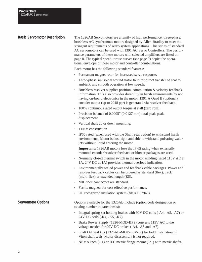
Figure 1AC Servomotor Configuration and Options
Resolver/EncoderSecondary Feedback Packages
Feedback Mounting KitsJunction Box Kit
Viton Shaft Oil Seal
Blower Cooling KitsIntegral Brake
(Internal to Motor)
90V DC BrakePower Supply
• Resolver Feedback Packages (1326AB-MOD-Vxxxx) provide 4.25”(108 mm) transducers which offer absolute/vernier or single brushlessresolver feedback for use with Allen-Bradley 8600GP, IMC rack and SClass motion controllers.
• Junction Box Kit (1326AB-MOD-RJxx) available with axially mountedconnectors. Connector version allows the motor connectors to bebrought out axially to the motor (rather than radially) without furtherwiring.
• Secondary Feedback Mounting Kits (1326AB-MOD-Mx) for fieldinstallation of an Allen-Bradley Encoder (845H) or resolver. Using a1326AB motor with a 1391B-ES (or 1391-DES) with A Quad Bfeedback (up to 2048 ppr) eliminates the need for encoder mounting.
• Blower Cooling Kit (1326AB-MOD-G3, G4) provides air over coolingfor up to 35% more torque output on most 1326AB “C” frame motors.The kit can be field mounted on the rear of 1326AB-Cxx motors (in-cluding motors with brakes). For motors using secondary motormounted feedback (1326AB-MOD-M60), use option “G4.”
• Cables for power (1326-CPxx . .) and feedback (1326-CFx . . - com-mutation, 1326-CEx . . - encoders) are available in lengths up to 100 ft.(30 m) for standard and high flex applications Power (1326ES-CPxx . .)and commutation (1326ES-CFx . .) cables over 100 ft. (30 m), up to 300ft. (90 m) are available when using 1391B-ES or 1391-DES drives only.
All kits are supplied as motor accessories and must be specified as aseparate item.
Product Data1326AB AC Servomotor
4
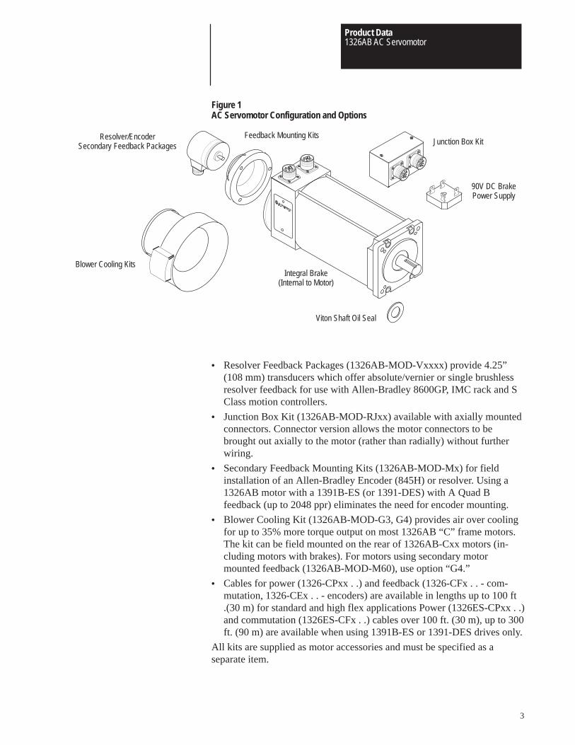
1326 A 3
First Position Second Position Third Position
BulletinNumber
Fourth Position
Max. Op.Speed
E
Fifth Position
Series
11
StandardOptions
–
Description
AC ServomotorPM Type
Letter
A
DesignMotorLength
Description
72 lb.-in. (8.1 N-m) Holding Brake w/90V DC Coil.120 lb.-in. (13.6 N-m) Holding Brake w/90V DC Coil.400 lb.-in. (45.2 N-m) Holding Brake w/90V DC Coil.
72 lb.-in. (8.1 N-m) Holding Brake w/24V DC Coil.120 lb.-in. (13.6 N-m) Holding Brake w/24V DC Coil.400 lb.-in. (45.2 N-m) Holding Brake w/24V DC Coil.
Code
A4A5A7
K4K5K7
Sixth Position
–B A
Type
Description
Factoryuse only
Eighth Position
–
1326AB Servomotor
Description
Sequentiallylettered todesignate framediameters.
Description
Sequentiallynumbered toindicate stacklength withina given framesize.
1326AB MOD
First Position Second Position Third Position
BulletinNumber
Fourth Position
MotorMounting 1
A
Fifth Position
Material
1–
Description
ModificationKit
Code
MOD
ShaftSeal
MotorSeries
Sixth Position
SS V
Type
–
Shaft Oil Seal Kit
Description
Viton
Letter
V
for . . .
-A Series-B Series-C Series
Letter
ABC
Description
Std. Inch
Metric
Number
1
2
–
Brake Power Supply Rectifier
1326 MOD BPS
BulletinNumber Type Description
–
Code
BPS
Description
Single-phase, full-wave, screw mount rectifierwith surge suppressor network. 115V AC input,for use with 90V DC brakes.2
Description
ModificationKit
Code
MOD
A4
Mounting & ShaftDescription
Description
4.25” (108 mm)
5.88” (149 mm)
7.63” (194 mm)
Code
A
B
C
Std.
1600
2000
3000
5000
Code
B
C
E
G
Seventh Position
Description
Inch CombinationFace/Flange withKeyway
NEMA/IEC MetricFlange withKeyway
Code
11
21
–
1 “A” Series motors with brake must use 1326AB-MOD-SSV-A2.
2 Up to 4 brakes per rectifier can be used.
ES/DES
2000
3000
4000
6000
RPM
Product Data1326AB AC Servomotor
5
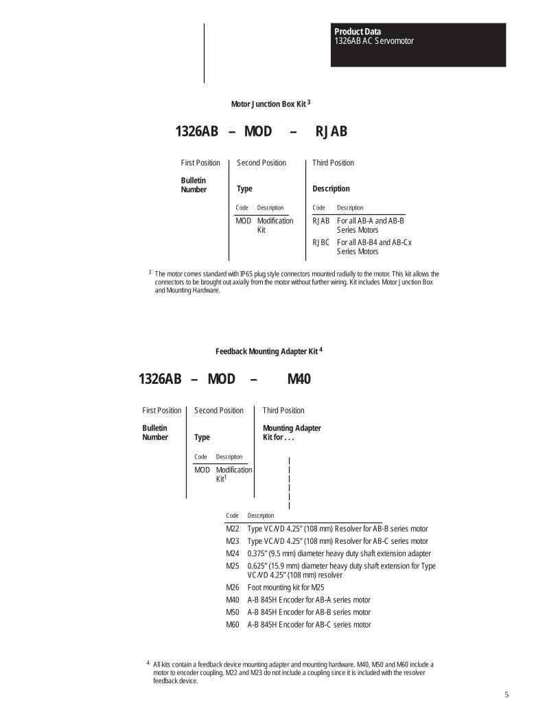
3 The motor comes standard with IP65 plug style connectors mounted radially to the motor. This kit allows theconnectors to be brought out axially from the motor without further wiring. Kit includes Motor Junction Boxand Mounting Hardware.
Motor Junction Box Kit 3
1326AB MOD RJAB
First Position Second Position Third Position
BulletinNumber Type Description
–
Code
RJAB
RJBC
Description
For all AB-A and AB-BSeries Motors
For all AB-B4 and AB-CxSeries Motors
Description
ModificationKit
Code
MOD
–
1326AB MOD
First Position Second Position Third Position
BulletinNumber
–
Description
ModificationKit1
Code
MOD
Mounting AdapterKit for . . .
M40
Type
Feedback Mounting Adapter Kit 4
–
Description
Type VC/VD 4.25” (108 mm) Resolver for AB-B series motor
Type VC/VD 4.25” (108 mm) Resolver for AB-C series motor
0.375” (9.5 mm) diameter heavy duty shaft extension adapter
0.625” (15.9 mm) diameter heavy duty shaft extension for TypeVC/VD 4.25” (108 mm) resolver
Foot mounting kit for M25
A-B 845H Encoder for AB-A series motor
A-B 845H Encoder for AB-B series motor
A-B 845H Encoder for AB-C series motor
Code
M22
M23
M24
M25
M26
M40
M50
M60
4 All kits contain a feedback device mounting adapter and mounting hardware. M40, M50 and M60 include amotor to encoder coupling. M22 and M23 do not include a coupling since it is included with the resolverfeedback device.
Product Data1326AB AC Servomotor
6
Feedback Coupling 5
1326 MOD C1
First Position Second Position Third Position
BulletinNumber Type
CouplingSize
–
Description
ModificationKit
Code
MOD
Code
C1
C2
Size – Motor Shaft to Encoder Shaft
3/8” to 3/8” (9.5 mm to 9.5 mm)
1/4” to 3/8” (6.4 mm to 9.5 mm)
–
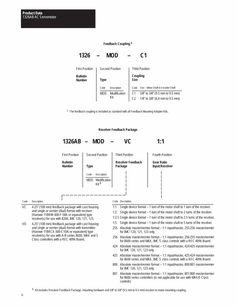
5 The feedback coupling is included as standard with all Feedback Mounting Adapter Kits.
6 Kit includes Resolver Feedback Package, mounting hardware and 3/8” to 3/8” (9.5 mm to 9.5 mm) resolver to motor mounting coupling.
1326AB MOD
First Position Second Position Third Position
BulletinNumber
Gear Ratio Input:Resolver
–
Description
ModificationKit 6
Code
MOD
VC
Type
Resolver Feedback Package
Code
1:1
1:2
1:2.5
1:5
255
256
424
425
800
801
–
Description
Single device format – 1 turn of the motor shaft to 1 turn of the resolver.
Single device format – 1 turn of the motor shaft to 2 turns of the resolver.
Single device format – 1 turn of the motor shaft to 2.5 turns of the resolver.
Single device format – 1 turn of the motor shaft to 5 turns of the resolver.
Absolute master/vernier format – 1:1 input/master, 255:256 master/vernierfor IMC] 120, 121, 123 only.
Absolute master/vernier format – 1:1 input/master, 256:255 master/vernierfor 8600 series and MAX, IMC S class controls with a REC 4096 Board.
Absolute master/vernier format – 1:1 input/master, 424:425 master/vernierfor IMC 120, 121, 123 only.
Absolute master/vernier format – 1:1 input/master, 425:424 master/vernierfor 8600 series and MAX, IMC S class controls with a REC 4096 Board.
Absolute master/vernier format – 1:1 input/master, 800:801 master/vernierfor IMC 120, 121, 123 only.
Absolute master/vernier format – 1:1 input/master, 801:800 master/vernierfor 8600 series controllers (is not applicable for use with MAX/S Classcontrols)
1:1
Fourth Position
Resolver FeedbackPackage
Code
VC
VD
Description
4.25” (108 mm) feedback package with cast housingand single or vernier (dual) format with receiver(Harowe 11BRW-300-F-58A or equivalent) typeresolver(s) for use with 8200, IMC 120, 121, 123.
4.25” (108 mm) feedback package with cast housingand single or vernier (dual) format with transmitter(Harowe 11BRCX-300-C10/6 or equivalent) typeresolver(s) for use with A-B series 8600, MAX and SClass controllers with a REC 4096 Board.
Product Data1326AB AC Servomotor
7
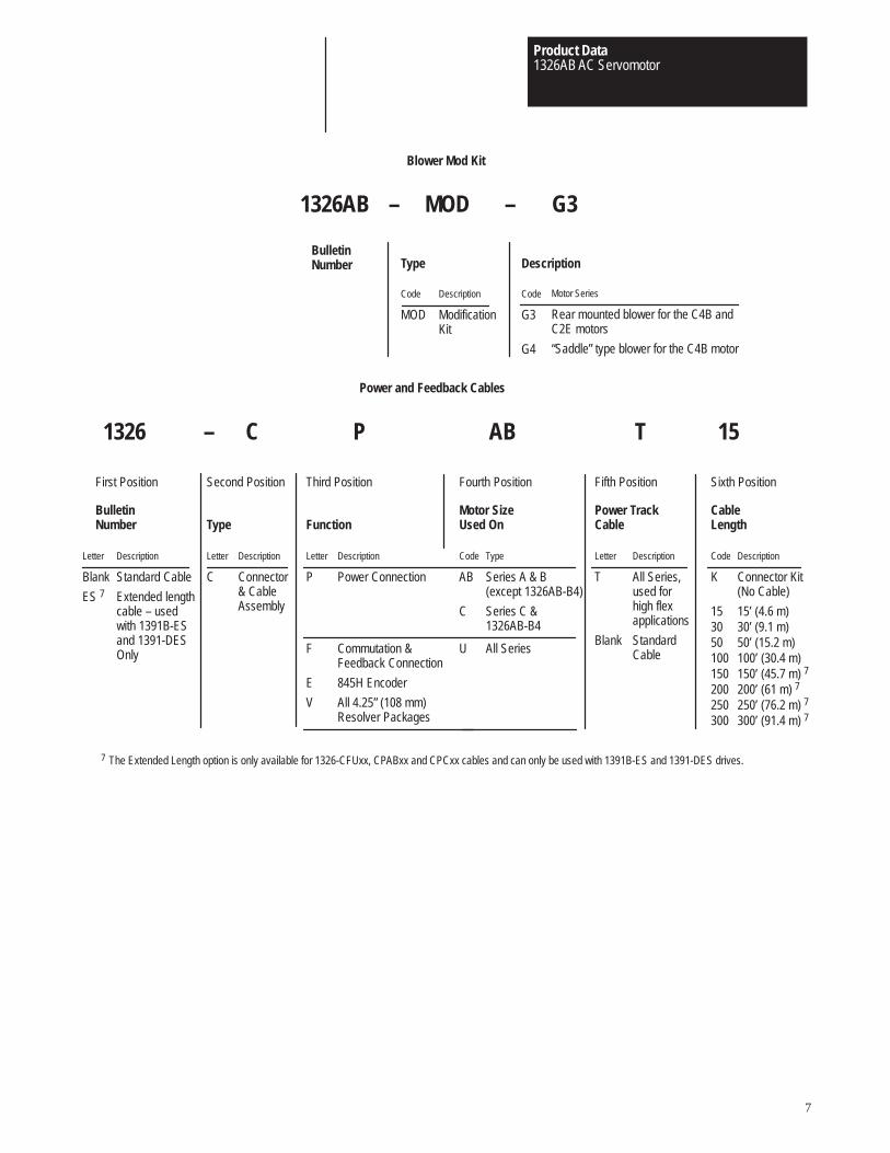
Blower Mod Kit
1326AB MOD G3
BulletinNumber Type Description
–
Description
ModificationKit
Code
MOD
Code
G3
G4
Motor Series
Rear mounted blower for the C4B andC2E motors
“Saddle” type blower for the C4B motor
–
1326 C
First Position Second Position Third Position
BulletinNumber
Sixth Position
Cable Length
–
Function
P AB
Type
Power and Feedback Cables
Description
Power Connection
Letter
P
15
Fourth Position
Motor SizeUsed On
Code
K
153050100150200250300
Description
Connector Kit(No Cable)
15’ (4.6 m)30’ (9.1 m)50’ (15.2 m)100’ (30.4 m)150’ (45.7 m) 7
200’ (61 m) 7
250’ (76.2 m) 7
300’ (91.4 m) 7
Commutation &Feedback Connection
845H Encoder
All 4.25” (108 mm)Resolver Packages
F
E
V
Description
Connector& CableAssembly
Letter
C
Type
Series A & B(except 1326AB-B4)
Series C &1326AB-B4
Code
AB
C
All SeriesU
T
Fifth Position
Power TrackCable
Description
All Series,used forhigh flexapplications
StandardCable
Letter
T
Blank
Description
Standard Cable
Extended lengthcable – usedwith 1391B-ESand 1391-DESOnly
Letter
Blank
ES 7
7 The Extended Length option is only available for 1326-CFUxx, CPABxx and CPCxx cables and can only be used with 1391B-ES and 1391-DES drives.
Product Data1326AB AC Servomotor
8
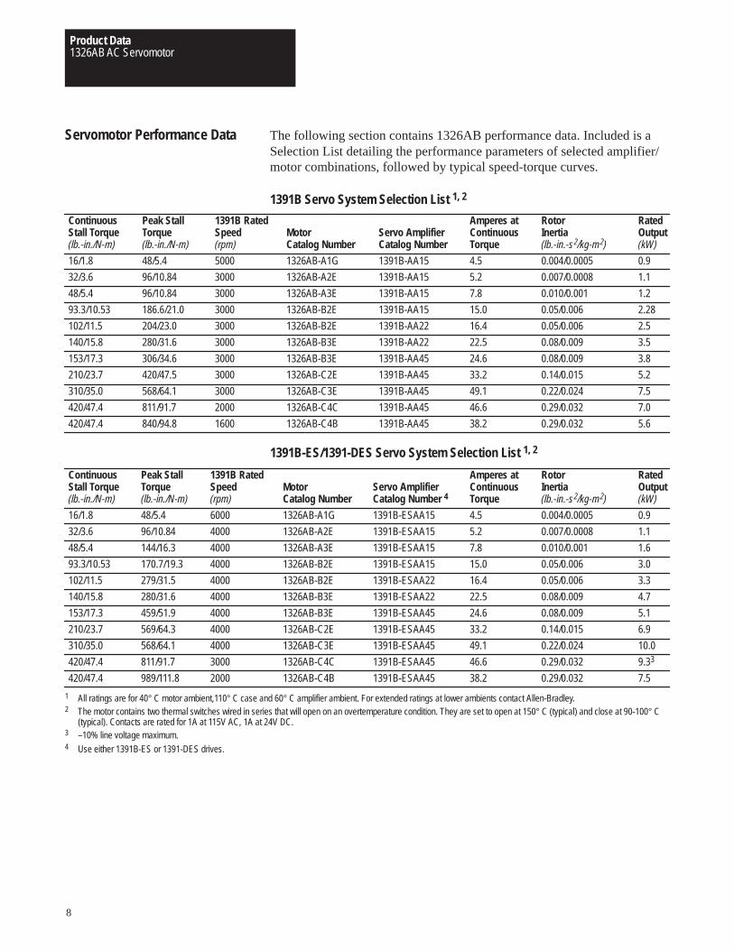
Servomotor Performance Data The following section contains 1326AB performance data. Included is aSelection List detailing the performance parameters of selected amplifier/motor combinations, followed by typical speed-torque curves.
1391B Servo System Selection List 1, 2
ContinuousStall Torque(lb.-in./N-m)
16/1.8
32/3.6
48/5.4
93.3/10.53
102/11.5
140/15.8
153/17.3
210/23.7
310/35.0
420/47.4
420/47.4
1391B RatedSpeed(rpm)
5000
3000
3000
3000
3000
3000
3000
3000
3000
2000
1600
MotorCatalog Number
1326AB-A1G
1326AB-A2E
1326AB-A3E
1326AB-B2E
1326AB-B2E
1326AB-B3E
1326AB-B3E
1326AB-C2E
1326AB-C3E
1326AB-C4C
1326AB-C4B
RatedOutput(kW)
0.9
1.1
1.2
2.28
2.5
3.5
3.8
5.2
7.5
7.0
5.6
Peak StallTorque(lb.-in./N-m)
48/5.4
96/10.84
96/10.84
186.6/21.0
204/23.0
280/31.6
306/34.6
420/47.5
568/64.1
811/91.7
840/94.8
RotorInertia(lb.-in.-s2/kg-m2)
0.004/0.0005
0.007/0.0008
0.010/0.001
0.05/0.006
0.05/0.006
0.08/0.009
0.08/0.009
0.14/0.015
0.22/0.024
0.29/0.032
0.29/0.032
Servo AmplifierCatalog Number
1391B-AA15
1391B-AA15
1391B-AA15
1391B-AA15
1391B-AA22
1391B-AA22
1391B-AA45
1391B-AA45
1391B-AA45
1391B-AA45
1391B-AA45
Amperes atContinuousTorque
4.5
5.2
7.8
15.0
16.4
22.5
24.6
33.2
49.1
46.6
38.2
1391B-ES/1391-DES Servo System Selection List 1, 2
ContinuousStall Torque(lb.-in./N-m)
16/1.8
32/3.6
48/5.4
93.3/10.53
102/11.5
140/15.8
153/17.3
210/23.7
310/35.0
420/47.4
420/47.4
1391B RatedSpeed(rpm)
6000
4000
4000
4000
4000
4000
4000
4000
4000
3000
2000
MotorCatalog Number
1326AB-A1G
1326AB-A2E
1326AB-A3E
1326AB-B2E
1326AB-B2E
1326AB-B3E
1326AB-B3E
1326AB-C2E
1326AB-C3E
1326AB-C4C
1326AB-C4B
RatedOutput(kW)
0.9
1.1
1.6
3.0
3.3
4.7
5.1
6.9
10.0
9.33
7.5
Peak StallTorque(lb.-in./N-m)
48/5.4
96/10.84
144/16.3
170.7/19.3
279/31.5
280/31.6
459/51.9
569/64.3
568/64.1
811/91.7
989/111.8
RotorInertia(lb.-in.-s2/kg-m2)
0.004/0.0005
0.007/0.0008
0.010/0.001
0.05/0.006
0.05/0.006
0.08/0.009
0.08/0.009
0.14/0.015
0.22/0.024
0.29/0.032
0.29/0.032
Servo AmplifierCatalog Number 4
1391B-ESAA15
1391B-ESAA15
1391B-ESAA15
1391B-ESAA15
1391B-ESAA22
1391B-ESAA22
1391B-ESAA45
1391B-ESAA45
1391B-ESAA45
1391B-ESAA45
1391B-ESAA45
Amperes atContinuousTorque
4.5
5.2
7.8
15.0
16.4
22.5
24.6
33.2
49.1
46.6
38.2
1 All ratings are for 40° C motor ambient,110° C case and 60° C amplifier ambient. For extended ratings at lower ambients contact Allen-Bradley.2 The motor contains two thermal switches wired in series that will open on an overtemperature condition. They are set to open at 150° C (typical) and close at 90-100° C
(typical). Contacts are rated for 1A at 115V AC, 1A at 24V DC.3 –10% line voltage maximum.4 Use either 1391B-ES or 1391-DES drives.
Product Data1326AB AC Servomotor
9
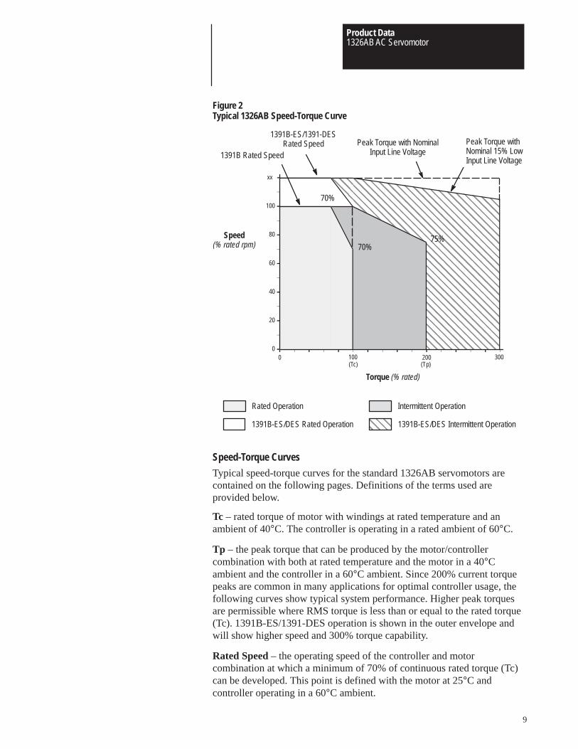
Figure 2Typical 1326AB Speed-Torque Curve
ÇÇÇÇÇÇÇÇÇÇÇÇÇÇÇÇÇÇÇÇÇÇÇÇÇÇÇÇÇÇÇÇÇÇÇÇÇÇÇÇÇÇÇÇÇÇÇÇÇÇÇÇÇÇÇÇÇÇÇÇÇÇÇÇÇÇÇÇÇÇÇÇÇÇÇÇÇÇ
ÇÇÇÇÇÇÇÇÇÇÇÇÇÇÇÇÇÇÇÇÇÇÇÇÇÇÇÇÇÇÇÇÇÇÇÇÇÇÇÇÇÇÇÇÇÇÇÇÇÇÇÇÇÇÇÇÇÇÇÇÇÇÇÇÇÇÇÇÇÇÇÇÇÇÇÇÇÇÇÇÇÇÇÇÇÇÇÇÇÇÇÇÇÇÇÇÇÇÇÇÇÇÇÇÇÇÇÇÇÇÇÇÇÇÇÇÇÇÇÇÇÇÇÇÇÇÇÇÇÇÇÇÇÇÇÇÇÇÇÇÇÇÇ
ÈÈÈÈÈÈÈÈÈÈÈÈÈÈÈÈÈÈÈÈÈÈÈÈÈÈÈÈÈÈÈÈÈÈÈÈÈÈÈÈÈÈÈÈÈÈÈÈÈÈÈÈ
ÈÈÈÈÈÈÈÈÈÈÈÈÈÈÈÈÈÈÈÈÈÈÈÈÈÈÈÈÈÈÈÈÈÈÈÈÈÈÈ
0
20
40
60
80
100
120
0 40 80 120 160 200 240 280
Speed(% rated rpm)
Torque (% rated)
75%
70%
70%
(Tc) (Tp)
Intermittent OperationRated Operation
Peak Torque with NominalInput Line Voltage1391B Rated Speed
Peak Torque withNominal 15% LowInput Line Voltage
1391B-ES/1391-DESRated Speed
ÇÇÇÇ
1391B-ES/DES Rated Operation 1391B-ES/DES Intermittent Operation
xx
100 300
Speed-Torque Curves
Typical speed-torque curves for the standard 1326AB servomotors arecontained on the following pages. Definitions of the terms used areprovided below.
Tc – rated torque of motor with windings at rated temperature and anambient of 40°C. The controller is operating in a rated ambient of 60°C.
Tp – the peak torque that can be produced by the motor/controllercombination with both at rated temperature and the motor in a 40°Cambient and the controller in a 60°C ambient. Since 200% current torquepeaks are common in many applications for optimal controller usage, thefollowing curves show typical system performance. Higher peak torquesare permissible where RMS torque is less than or equal to the rated torque(Tc). 1391B-ES/1391-DES operation is shown in the outer envelope andwill show higher speed and 300% torque capability.
Rated Speed – the operating speed of the controller and motorcombination at which a minimum of 70% of continuous rated torque (Tc)can be developed. This point is defined with the motor at 25°C andcontroller operating in a 60°C ambient.
Product Data1326AB AC Servomotor
10
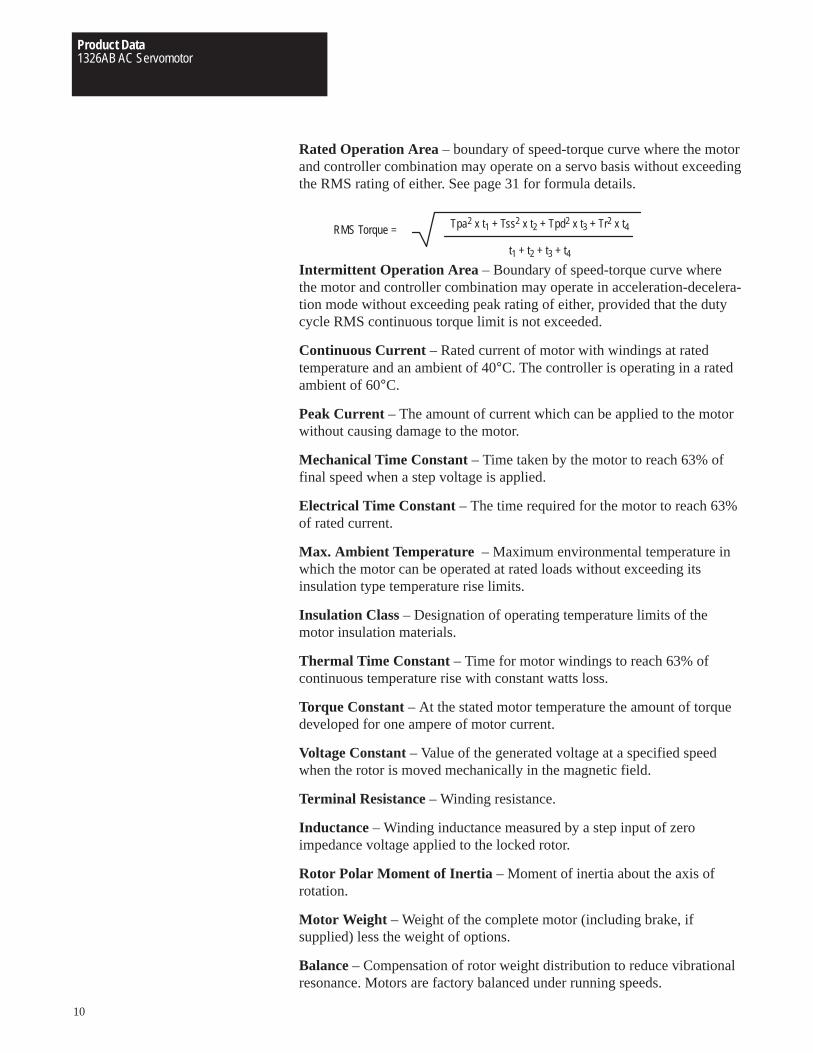
Rated Operation Area – boundary of speed-torque curve where the motorand controller combination may operate on a servo basis without exceedingthe RMS rating of either. See page 31 for formula details.
Tpa2 x t1 + Tss2 x t2 + Tpd2 x t3 + Tr2 x t4
t1 + t2 + t3 + t4
RMS Torque =
Intermittent Operation Area – Boundary of speed-torque curve wherethe motor and controller combination may operate in acceleration-decelera-tion mode without exceeding peak rating of either, provided that the dutycycle RMS continuous torque limit is not exceeded.
Continuous Current – Rated current of motor with windings at ratedtemperature and an ambient of 40°C. The controller is operating in a ratedambient of 60°C.
Peak Current – The amount of current which can be applied to the motorwithout causing damage to the motor.
Mechanical Time Constant – Time taken by the motor to reach 63% offinal speed when a step voltage is applied.
Electrical Time Constant – The time required for the motor to reach 63%of rated current.
Max. Ambient Temperature – Maximum environmental temperature inwhich the motor can be operated at rated loads without exceeding itsinsulation type temperature rise limits.
Insulation Class – Designation of operating temperature limits of themotor insulation materials.
Thermal Time Constant – Time for motor windings to reach 63% ofcontinuous temperature rise with constant watts loss.
Torque Constant – At the stated motor temperature the amount of torquedeveloped for one ampere of motor current.
Voltage Constant – Value of the generated voltage at a specified speedwhen the rotor is moved mechanically in the magnetic field.
Terminal Resistance – Winding resistance.
Inductance – Winding inductance measured by a step input of zeroimpedance voltage applied to the locked rotor.
Rotor Polar Moment of Inertia – Moment of inertia about the axis ofrotation.
Motor Weight – Weight of the complete motor (including brake, ifsupplied) less the weight of options.
Balance – Compensation of rotor weight distribution to reduce vibrationalresonance. Motors are factory balanced under running speeds.
Product Data1326AB AC Servomotor
11
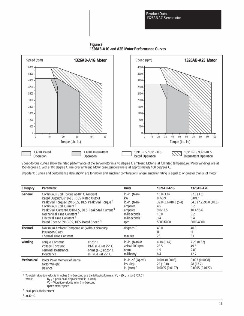
Figure 31326AB-A1G and A2E Motor Performance Curves
Category
General
Thermal
Winding
Mechanical
Parameter
Continuous Stall Torque at 40° C AmbientRated Output/1391B-ES, DES Rated OutputPeak Stall Torque/1391B-ES, DES Peak Stall Torque 3
Continuous Stall Current 3
Peak Stall Current/1391B-ES, DES Peak Stall Current 3
Mechanical Time Constant 3
Electrical Time Constant 3
Rated Speed/1391B-ES, DES Rated Speed 3
Maximum Ambient Temperature (without derating)Insulation ClassThermal Time Constant
Torque Constant at 25° CVoltage Constant RMS (L-L) at 25° CTerminal Resistance ohms (L-L) at 25° CInductance mH (L-L) at 25° C
Rotor Polar Moment of InertiaMotor WeightBalance 1
Units
lb.-in. (N-m)kWlb.-in. (N-m)amperesamperesmillisecondsmillisecondsrpm
degrees C
minutes
lb.-in. (N-m)/Avolts/1000 rpmohmsmillihenry
lb.-in.-s2 (kg-m2)lbs. (kg)in. (mm) 2
1326AB-A1G
16.0 (1.8)0.7/0.932.0 (3.6)/48.0 (5.4)4.59.0/13.510.03.45000/6000
40.0H23
4.18 (0.47)28.51.98.4
0.004 (0.0005)22 (10.0)0.0005 (0.0127)
1326AB-A2E
32.0 (3.6)0.8/1.164.0 (7.2)/96.0 (10.8)5.210.4/15.69.23.43000/4000
40.0H33
7.23 (0.82)49.52.8912.7
0.007 (0.0008)28 (12.7)0.0005 (0.0127)
1 To obtain vibration velocity in inches (mm)/second use the following formula: VV = (Dp-p x rpm) / 27.01where: Dp-p = peak-peak displacement in in. (mm)
VV = Vibration velocity in in. (mm)/secondrpm = motor speed
2 peak-peak displacement3 at 40° C
ÇÇÇÇÇÇÇÇÇÇÇÇÇÇÇÇÇÇÇÇÇÇÇÇÇÇÇÇÇÇÇÇÇÇÇÇÇÇÇÇÇÇÇÇÇÇÇÇÇÇÇÇÇÇÇ
ÇÇÇÇÇÇÇÇÇÇÇÇÇÇÇÇÇÇÇÇÇÇÇÇÇÇÇÇÇÇÇÇÇÇÇÇÇÇÇÇÇÇÇÇÇÇÇÇÇÇÇÇÇÇÇÇÇÇÇÇÇÇÇÇÇÇÇÇÇÇÇÇÇÇÇÇÇÇÇÇÇÇÇÇÇÇÇÇ
ÈÈÈÈÈÈÈÈÈÈÈÈÈÈÈÈÈÈÈÈÈÈÈÈÈÈÈÈÈÈÈÈÈÈÈÈÈÈÈÈÈÈÈÈ
ÈÈÈÈÈÈÈÈÈÈÈÈÈÈÈÈÈÈÈÈÈÈ0
600
1200
1800
2400
3000
3600
4200
4800
5400
6000
0 10 20 30 40 50
Speed (rpm)
Torque (Lb.-In.)
1391B IntermittentOperation
1391B RatedOperation
1391B-ES/1391-DESRated Operation
ÇÇÇÇ
1391B-ES/1391-DESIntermittent Operation
ÇÇÇÇÇÇÇÇÇÇÇÇÇÇÇÇÇÇÇÇÇÇÇÇÇÇÇÇÇÇÇÇÇÇÇÇÇÇÇÇÇÇÇÇÇÇÇÇÇÇÇÇÇÇÇ
ÇÇÇÇÇÇÇÇÇÇÇÇÇÇÇÇÇÇÇÇÇÇÇÇÇÇÇÇÇÇÇÇÇÇÇÇÇÇÇÇÇÇÇÇÇÇÇÇÇÇÇÇÇÇÇÇÇÇÇÇÇÇÇÇÇÇÇÇÇÇÇÇÇÇÇÇÇÇÇÇÇÇÇÇÇÇÇÇ
ÈÈÈÈÈÈÈÈÈÈÈÈÈÈÈÈÈÈÈÈÈÈÈÈÈÈÈÈÈÈÈÈÈÈÈÈÈÈÈÈÈÈÈÈ
ÈÈÈÈÈÈÈÈÈÈÈÈÈÈÈÈÈÈÈÈÈÈ0
400
800
1200
1600
2000
2400
2800
3200
3600
4000
0 10 20 30 40 50 60 70 80 90 100
Speed (rpm)
Torque (Lb.-In.)
1326AB-A1G Motor 1326AB-A2E Motor
Speed-torque curves show the rated performance of the servomotor in a 40 degree C ambient. Motor is at full rated temperature. Motor windings are at150 degrees C with a 110 degree C rise over ambient. Motor case temperature is at approximately 100 degrees C.
Important: Curves and performance data shown are for motor and amplifier combinations where amplifier rating is equal to or greater than Ic of motor
Product Data1326AB AC Servomotor
12
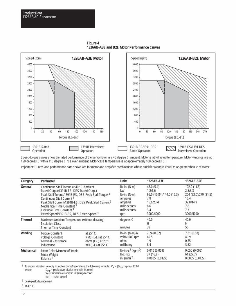
Figure 41326AB-A3E and B2E Motor Performance Curves
Category
General
Thermal
Winding
Mechanical
Units
lb.-in. (N-m)kWlb.-in. (N-m)amperesamperesmillisecondsmillisecondsrpm
degrees C
minutes
lb.-in. (N-m)/Avolts/1000 rpmohmsmillihenry
lb.-in.-s2 (kg-m2)lbs. (kg)in. (mm) 2
1326AB-A3E
48.0 (5.4)1.2/1.696.0 (10.84)/144.0 (16.3)7.815.6/23.48.63.43000/4000
40.0H38
7.24 (0.82)49.51.98.4
0.010 (0.001)37 (16.8)0.0005 (0.0127)
1326AB-B2E
102.0 (11.5)2.5/3.3204 (23.0)/279 (31.5)16.432.8/44.97.87.73000/4000
40.0H56
7.31 (0.83)49.90.353.52
0.050 (0.006)61 (27.7)0.0005 (0.0127)
Torque (Lb.-In.) Torque (Lb.-In.)
1326AB-A3E Motor 1326AB-B2E Motor
Speed-torque curves show the rated performance of the servomotor in a 40 degree C ambient. Motor is at full rated temperature. Motor windings are at150 degrees C with a 110 degree C rise over ambient. Motor case temperature is at approximately 100 degrees C.
Important: Curves and performance data shown are for motor and amplifier combinations where amplifier rating is equal to or greater than Ic of motor
Speed (rpm) Speed (rpm)
ÇÇÇÇÇÇÇÇÇÇÇÇÇÇÇÇÇÇÇÇÇÇÇÇÇÇÇÇÇÇÇÇÇÇÇÇÇÇÇÇÇÇÇÇÇÇÇÇÇÇÇÇÇÇÇÇÇÇÇÇ
ÇÇÇÇÇÇÇÇÇÇÇÇÇÇÇÇÇÇÇÇÇÇÇÇÇÇÇÇÇÇÇÇÇÇÇÇÇÇÇÇÇÇÇÇÇÇÇÇÇÇÇÇÇÇÇÇÇÇÇÇÇÇÇÇÇÇÇÇÇÇÇÇÇÇÇÇÇÇÇÇÇÇÇÇ
ÈÈÈÈÈÈÈÈÈÈÈÈÈÈÈÈÈÈÈÈÈÈÈÈÈÈÈÈÈÈÈÈÈÈÈÈÈÈÈÈÈÈÈÈÈÈÈÈ
ÈÈÈÈÈÈÈÈÈÈÈÈÈÈÈÈÈÈÈÈÈÈÈÈ0
400
800
1200
1600
2000
2400
2800
3200
3600
4000
0 20 40 60 80 100 120 140 160
ÇÇÇÇÇÇÇÇÇÇÇÇÇÇÇÇÇÇÇÇÇÇÇÇÇÇÇÇÇÇÇÇÇÇÇÇÇÇÇÇÇÇÇÇÇÇÇÇÇÇÇÇÇÇÇÇÇÇÇÇ
ÇÇÇÇÇÇÇÇÇÇÇÇÇÇÇÇÇÇÇÇÇÇÇÇÇÇÇÇÇÇÇÇÇÇÇÇÇÇÇÇÇÇÇÇÇÇÇÇÇÇÇÇÇÇÇÇÇÇÇÇÇÇÇÇÇÇÇÇÇÇÇÇÇÇÇÇÇÇÇÇÇÇÇÇÇÇÇÇÇÇÇÇÇÇÇÇ
ÈÈÈÈÈÈÈÈÈÈÈÈÈÈÈÈÈÈÈÈÈÈÈÈÈÈÈÈÈÈÈÈÈÈÈÈÈÈÈÈÈÈÈÈÈÈÈÈ
ÈÈÈÈÈÈÈÈÈÈÈÈÈÈÈÈÈÈÈÈÈÈÈÈ0
400
800
1200
1600
2000
2400
2800
3200
3600
4000
0 30 60 90 120 150 180 210 240 270
ÇÇÇÇ
Parameter
Continuous Stall Torque at 40° C AmbientRated Output/1391B-ES, DES Rated OutputPeak Stall Torque/1391B-ES, DES Peak Stall Torque 3
Continuous Stall Current 3
Peak Stall Current/1391B-ES, DES Peak Stall Current 3
Mechanical Time Constant 3
Electrical Time Constant 3
Rated Speed/1391B-ES, DES Rated Speed 3
Maximum Ambient Temperature (without derating)Insulation ClassThermal Time Constant
Torque Constant at 25° CVoltage Constant RMS (L-L) at 25° CTerminal Resistance ohms (L-L) at 25° CInductance mH (L-L) at 25° C
Rotor Polar Moment of InertiaMotor WeightBalance 1
1 To obtain vibration velocity in inches (mm)/second use the following formula: VV = (Dp-p x rpm) / 27.01where: Dp-p = peak-peak displacement in in. (mm)
VV = Vibration velocity in in. (mm)/secondrpm = motor speed
2 peak-peak displacement3 at 40° C
1391B IntermittentOperation
1391B RatedOperation
1391B-ES/1391-DESRated Operation
1391B-ES/1391-DESIntermittent Operation
Product Data1326AB AC Servomotor
13
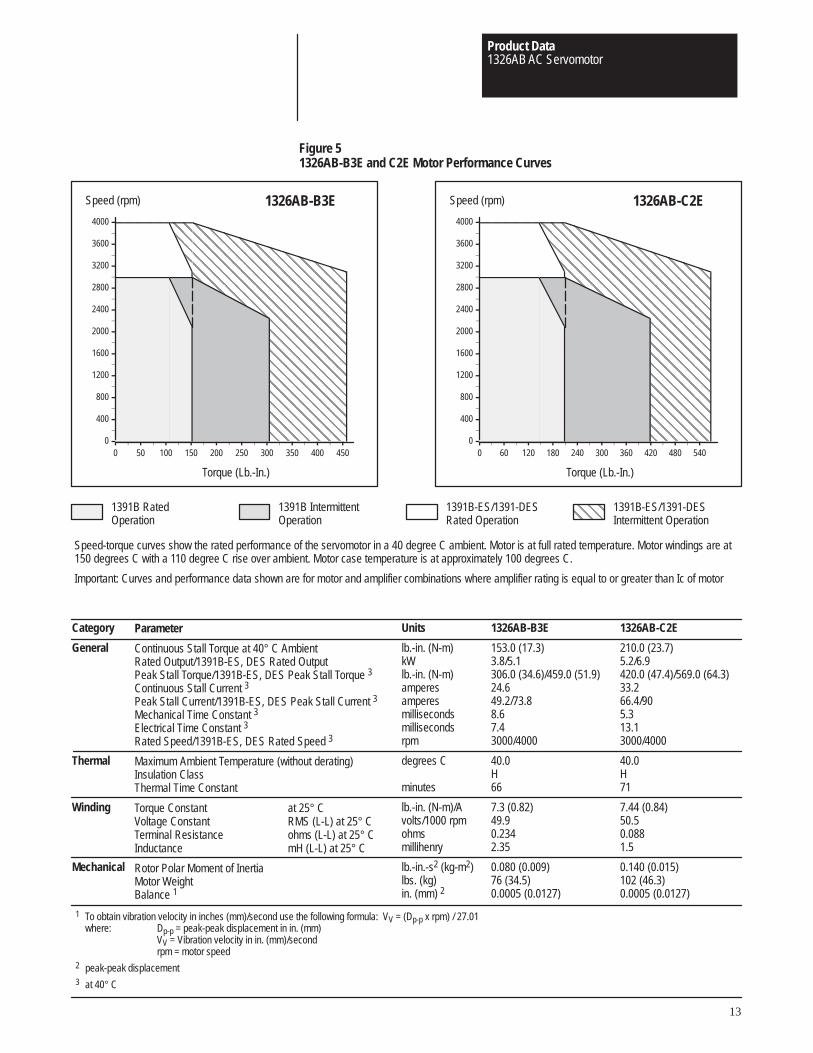
Figure 51326AB-B3E and C2E Motor Performance Curves
Category
General
Thermal
Winding
Mechanical
Units
lb.-in. (N-m)kWlb.-in. (N-m)amperesamperesmillisecondsmillisecondsrpm
degrees C
minutes
lb.-in. (N-m)/Avolts/1000 rpmohmsmillihenry
lb.-in.-s2 (kg-m2)lbs. (kg)in. (mm) 2
1326AB-B3E
153.0 (17.3)3.8/5.1306.0 (34.6)/459.0 (51.9)24.649.2/73.88.67.43000/4000
40.0H66
7.3 (0.82)49.90.2342.35
0.080 (0.009)76 (34.5)0.0005 (0.0127)
1326AB-C2E
210.0 (23.7)5.2/6.9420.0 (47.4)/569.0 (64.3)33.266.4/905.313.13000/4000
40.0H71
7.44 (0.84)50.50.0881.5
0.140 (0.015)102 (46.3)0.0005 (0.0127)
Torque (Lb.-In.) Torque (Lb.-In.)
1326AB-B3E 1326AB-C2E
Speed-torque curves show the rated performance of the servomotor in a 40 degree C ambient. Motor is at full rated temperature. Motor windings are at150 degrees C with a 110 degree C rise over ambient. Motor case temperature is at approximately 100 degrees C.
Important: Curves and performance data shown are for motor and amplifier combinations where amplifier rating is equal to or greater than Ic of motor
Speed (rpm) Speed (rpm)
ÇÇÇÇÇÇÇÇÇÇÇÇÇÇÇÇÇÇÇÇÇÇÇÇÇÇÇÇÇÇÇÇÇÇÇÇÇÇÇÇÇÇÇÇÇÇÇÇÇÇÇÇÇÇÇÇÇÇÇÇ
ÇÇÇÇÇÇÇÇÇÇÇÇÇÇÇÇÇÇÇÇÇÇÇÇÇÇÇÇÇÇÇÇÇÇÇÇÇÇÇÇÇÇÇÇÇÇÇÇÇÇÇÇÇÇÇÇÇÇÇÇÇÇÇÇÇÇÇÇÇÇÇÇÇÇÇÇÇÇÇÇÇÇÇÇÇÇÇÇÇÇÇÇÇÇÇÇ
ÈÈÈÈÈÈÈÈÈÈÈÈÈÈÈÈÈÈÈÈÈÈÈÈÈÈÈÈÈÈÈÈÈÈÈÈÈÈÈÈÈÈÈÈÈÈÈÈ
ÈÈÈÈÈÈÈÈÈÈÈÈÈÈÈÈÈÈÈÈÈÈÈÈ0
400
800
1200
1600
2000
2400
2800
3200
3600
4000
0 50 100 150 200 250 300 350 400 450
ÇÇÇÇÇÇÇÇÇÇÇÇÇÇÇÇÇÇÇÇÇÇÇÇÇÇÇÇÇÇÇÇÇÇÇÇÇÇÇÇÇÇÇÇÇÇÇÇÇÇÇÇÇÇÇÇÇÇÇÇ
ÇÇÇÇÇÇÇÇÇÇÇÇÇÇÇÇÇÇÇÇÇÇÇÇÇÇÇÇÇÇÇÇÇÇÇÇÇÇÇÇÇÇÇÇÇÇÇÇÇÇÇÇÇÇÇÇÇÇÇÇÇÇÇÇÇÇÇÇÇÇÇÇÇÇÇÇÇÇÇÇÇÇÇÇÇÇÇÇÇÇÇÇÇÇÇÇ
ÈÈÈÈÈÈÈÈÈÈÈÈÈÈÈÈÈÈÈÈÈÈÈÈÈÈÈÈÈÈÈÈÈÈÈÈÈÈÈÈÈÈÈÈÈÈÈÈ
ÈÈÈÈÈÈÈÈÈÈÈÈÈÈÈÈÈÈÈÈÈÈÈÈ0
400
800
1200
1600
2000
2400
2800
3200
3600
4000
0 60 120 180 240 300 360 420 480 540
ÇÇÇÇ
Parameter
Continuous Stall Torque at 40° C AmbientRated Output/1391B-ES, DES Rated OutputPeak Stall Torque/1391B-ES, DES Peak Stall Torque 3
Continuous Stall Current 3
Peak Stall Current/1391B-ES, DES Peak Stall Current 3
Mechanical Time Constant 3
Electrical Time Constant 3
Rated Speed/1391B-ES, DES Rated Speed 3
Maximum Ambient Temperature (without derating)Insulation ClassThermal Time Constant
Torque Constant at 25° CVoltage Constant RMS (L-L) at 25° CTerminal Resistance ohms (L-L) at 25° CInductance mH (L-L) at 25° C
Rotor Polar Moment of InertiaMotor WeightBalance 1
1 To obtain vibration velocity in inches (mm)/second use the following formula: VV = (Dp-p x rpm) / 27.01where: Dp-p = peak-peak displacement in in. (mm)
VV = Vibration velocity in in. (mm)/secondrpm = motor speed
2 peak-peak displacement3 at 40° C
1391B IntermittentOperation
1391B RatedOperation
1391B-ES/1391-DESRated Operation
1391B-ES/1391-DESIntermittent Operation
Product Data1326AB AC Servomotor
14
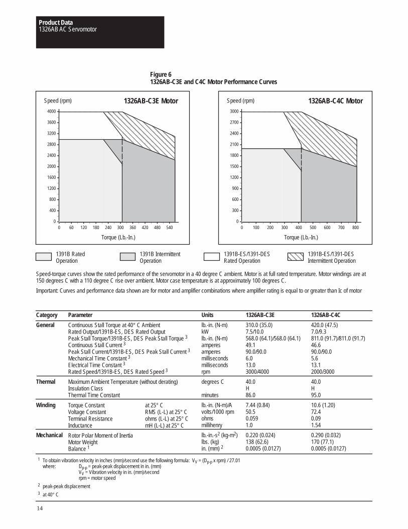
Figure 61326AB-C3E and C4C Motor Performance Curves
Category
General
Thermal
Winding
Mechanical
Units
lb.-in. (N-m)kWlb.-in. (N-m)amperesamperesmillisecondsmillisecondsrpm
degrees C
minutes
lb.-in. (N-m)/Avolts/1000 rpmohmsmillihenry
lb.-in.-s2 (kg-m2)lbs. (kg)in. (mm) 2
1326AB-C3E
310.0 (35.0)7.5/10.0568.0 (64.1)/568.0 (64.1)49.190.0/90.06.013.03000/4000
40.0H86.0
7.44 (0.84)50.50.0591.0
0.220 (0.024)138 (62.6)0.0005 (0.0127)
1326AB-C4C
420.0 (47.5)7.0/9.3811.0 (91.7)/811.0 (91.7)46.690.0/90.05.613.12000/3000
40.0H95.0
10.6 (1.20)72.40.091.54
0.290 (0.032)170 (77.1)0.0005 (0.0127)
Speed (rpm)
Torque (Lb.-In.)
Speed (rpm)
Torque (Lb.-In.)
1326AB-C3E Motor 1326AB-C4C MotorÇÇÇÇÇÇÇÇÇÇÇÇÇÇÇÇÇÇÇÇÇÇÇÇÇÇÇÇÇÇÇÇÇÇÇÇÇÇÇÇÇÇÇÇÇÇÇÇÇÇÇÇÇÇÇÇÇÇÇÇÇÇÇÇÇÇÇÇÇÇÇÇÇÇÇÇÇÇÇÇÇÇÇÇ
ÇÇÇÇÇÇÇÇÇÇÇÇÇÇÇÇÇÇÇÇÇÇÇÇÇÇÇÇÇÇÇÇÇÇÇÇÇÇÇÇÇÇÇÇÇÇÇÇÇÇÇÇÇÇÇÇÇÇÇÇÇÇÇÇÇÇÇÇÇÇÇÇÇÇÇÇÇÇÇÇÇÇÇÇ
ÈÈÈÈÈÈÈÈÈÈÈÈÈÈÈÈÈÈÈÈÈÈÈÈÈÈÈÈÈÈÈÈÈÈÈÈÈÈÈÈÈÈÈÈÈÈÈÈÈÈÈÈÈÈÈÈÈÈÈÈÈÈÈÈÈÈÈÈÈÈÈÈ
ÈÈÈÈÈÈÈÈÈÈÈÈÈÈÈÈÈÈÈÈÈÈÈÈ0
400
800
1200
1600
2000
2400
2800
3200
3600
4000
0 60 120 180 240 300 360 420 480 540
ÇÇÇÇÇÇÇÇÇÇÇÇÇÇÇÇÇÇÇÇÇÇÇÇÇÇÇÇÇÇÇÇÇÇÇÇÇÇÇÇÇÇÇÇÇÇÇÇÇÇÇÇÇÇÇÇÇÇÇÇÇÇÇÇÇÇÇÇÇÇÇÇÇÇÇÇÇÇÇÇÇÇÇÇ
ÇÇÇÇÇÇÇÇÇÇÇÇÇÇÇÇÇÇÇÇÇÇÇÇÇÇÇÇÇÇÇÇÇÇÇÇÇÇÇÇÇÇÇÇÇÇÇÇÇÇÇÇÇÇÇÇÇÇÇÇÇÇÇÇÇÇÇÇÇÇÇÇ
ÈÈÈÈÈÈÈÈÈÈÈÈÈÈÈÈÈÈÈÈÈÈÈÈÈÈÈÈÈÈÈÈÈÈÈÈÈÈÈÈÈÈÈÈÈÈÈÈÈÈÈÈÈÈÈÈÈÈÈÈ
ÈÈÈÈÈÈÈÈÈÈÈÈÈÈÈÈÈÈÈÈÈÈÈÈÈÈÈÈÈÈÈÈÈÈÈÈ0
300
600
900
1200
1500
1800
2100
2400
2700
3000
0 100 200 300 400 500 600 700 800
Speed-torque curves show the rated performance of the servomotor in a 40 degree C ambient. Motor is at full rated temperature. Motor windings are at150 degrees C with a 110 degree C rise over ambient. Motor case temperature is at approximately 100 degrees C.
Important: Curves and performance data shown are for motor and amplifier combinations where amplifier rating is equal to or greater than Ic of motor
ÇÇÇÇ
Parameter
Continuous Stall Torque at 40° C AmbientRated Output/1391B-ES, DES Rated OutputPeak Stall Torque/1391B-ES, DES Peak Stall Torque 3
Continuous Stall Current 3
Peak Stall Current/1391B-ES, DES Peak Stall Current 3
Mechanical Time Constant 3
Electrical Time Constant 3
Rated Speed/1391B-ES, DES Rated Speed 3
Maximum Ambient Temperature (without derating)Insulation ClassThermal Time Constant
Torque Constant at 25° CVoltage Constant RMS (L-L) at 25° CTerminal Resistance ohms (L-L) at 25° CInductance mH (L-L) at 25° C
Rotor Polar Moment of InertiaMotor WeightBalance 1
1 To obtain vibration velocity in inches (mm)/second use the following formula: VV = (Dp-p x rpm) / 27.01where: Dp-p = peak-peak displacement in in. (mm)
VV = Vibration velocity in in. (mm)/secondrpm = motor speed
2 peak-peak displacement3 at 40° C
1391B IntermittentOperation
1391B RatedOperation
1391B-ES/1391-DESRated Operation
1391B-ES/1391-DESIntermittent Operation
Product Data1326AB AC Servomotor
15
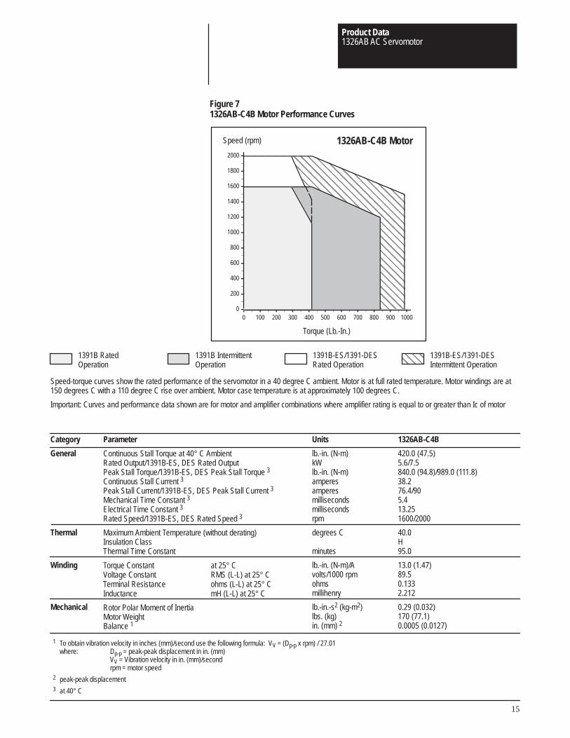
Figure 71326AB-C4B Motor Performance Curves
Category
General
Thermal
Winding
Mechanical
Units
lb.-in. (N-m)kWlb.-in. (N-m)amperesamperesmillisecondsmillisecondsrpm
degrees C
minutes
lb.-in. (N-m)/Avolts/1000 rpmohmsmillihenry
lb.-in.-s2 (kg-m2)lbs. (kg)in. (mm) 2
1326AB-C4B
420.0 (47.5)5.6/7.5840.0 (94.8)/989.0 (111.8)38.276.4/905.413.251600/2000
40.0H95.0
13.0 (1.47)89.50.1332.212
0.29 (0.032)170 (77.1)0.0005 (0.0127)
Speed (rpm)
Torque (Lb.-In.)
1326AB-C4B Motor
Speed-torque curves show the rated performance of the servomotor in a 40 degree C ambient. Motor is at full rated temperature. Motor windings are at150 degrees C with a 110 degree C rise over ambient. Motor case temperature is at approximately 100 degrees C.
Important: Curves and performance data shown are for motor and amplifier combinations where amplifier rating is equal to or greater than Ic of motor
ÇÇÇÇÇÇÇÇÇÇÇÇÇÇÇÇÇÇÇÇÇÇÇÇÇÇÇÇÇÇÇÇÇÇÇÇÇÇÇÇÇÇÇÇÇÇÇÇÇÇÇÇÇÇÇÇÇÇÇÇ
ÇÇÇÇÇÇÇÇÇÇÇÇÇÇÇÇÇÇÇÇÇÇÇÇÇÇÇÇÇÇÇÇÇÇÇÇÇÇÇÇÇÇÇÇÇÇÇÇÇÇÇÇÇÇÇÇÇÇÇÇÇÇÇÇÇÇÇÇÇÇÇÇÇÇÇÇÇÇÇÇÇÇÇÇÇÇÇÇÇÇÇÇÇÇÇÇ
ÈÈÈÈÈÈÈÈÈÈÈÈÈÈÈÈÈÈÈÈÈÈÈÈÈÈÈÈÈÈÈÈÈÈÈÈÈÈÈÈÈÈÈÈÈÈÈÈ
ÈÈÈÈÈÈÈÈÈÈÈÈÈÈÈÈÈÈÈÈÈÈÈÈ0
200
400
600
800
1000
1200
1400
1600
1800
2000
0 100 200 300 400 500 600 700 800 900 1000
ÇÇÇÇ
Parameter
Continuous Stall Torque at 40° C AmbientRated Output/1391B-ES, DES Rated OutputPeak Stall Torque/1391B-ES, DES Peak Stall Torque 3
Continuous Stall Current 3
Peak Stall Current/1391B-ES, DES Peak Stall Current 3
Mechanical Time Constant 3
Electrical Time Constant 3
Rated Speed/1391B-ES, DES Rated Speed 3
Maximum Ambient Temperature (without derating)Insulation ClassThermal Time Constant
Torque Constant at 25° CVoltage Constant RMS (L-L) at 25° CTerminal Resistance ohms (L-L) at 25° CInductance mH (L-L) at 25° C
Rotor Polar Moment of InertiaMotor WeightBalance 1
1 To obtain vibration velocity in inches (mm)/second use the following formula: VV = (Dp-p x rpm) / 27.01where: Dp-p = peak-peak displacement in in. (mm)
VV = Vibration velocity in in. (mm)/secondrpm = motor speed
2 peak-peak displacement3 at 40° C
1391B IntermittentOperation
1391B RatedOperation
1391B-ES/1391-DESRated Operation
1391B-ES/1391-DESIntermittent Operation
Product Data1326AB AC Servomotor
16
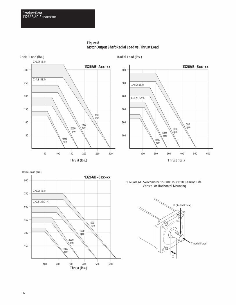
Figure 8Motor Output Shaft Radial Load vs. Thrust Load
50
50 100 150 200 250 300
100
150
200
250
300
Radial Load (lbs.)
Thrust (lbs.)
100
100 200 300 400 500 600
200
300
400
500
600
Radial Load (lbs.)
Thrust (lbs.)
150
100 200 300 400 500 600
300
450
600
750
900
Radial Load (lbs.)
Thrust (lbs.)
X=0.25 (6.4)
X=2.8125 (71.4)
2000rpm
1000rpm
500rpm
4000rpm
X=0.25 (6.4)
X=1.9 (48.3)
2000rpm
4000rpm
X=0.25 (6.4)
X=2.28 (57.9)
2000rpm
1000rpm
500rpm
4000rpm
T (Axial Force)
R (Radial Force)
X
1326AB AC Servomotor 15,000 Hour B10 Bearing Life Vertical or Horizontal Mounting
1326AB–Cxx–xx
1326AB–Axx–xx 1326AB–Bxx–xx
1000rpm
100rpm
Product Data1326AB AC Servomotor
17
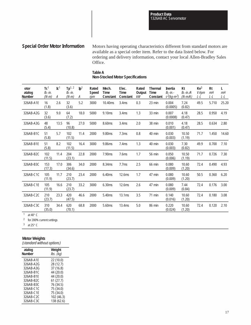
Special Order Motor Information Motors having operating characteristics different from standard motors areavailable as a special order item. Refer to the data listed below. Forordering and delivery information, contact your local Allen-Bradley SalesOffice.
Table ANon-Stocked Motor Specifications
otoratalog
Number
326AB-A1E
326AB-A2G
326AB-A3G
326AB-B1C
326AB-B1E
326AB-B2C
326AB-B3C
326AB-C1C
326AB-C1E
326AB-C2C
326AB-C3C
Ic1
A
2.6
9.0
13.5
5.7
8.2
11.4
17.0
11.7
16.6
23.3
34.4
Tc1
lb.-in.(N-m)
16(1.8)
32(3.6)
48(5.4)
51(5.8)
51(5.8)
102(11.5)
153(17.3)
105(11.9)
105(11.9)
210(23.7)
310(35.0)
Tp1, 2
lb.-in.(N-m)
32(3.6)
64(7.2)
96(10.8)
102(11.5)
102(11.5)
204(23.1)
306(34.6)
210(23.7)
210(23.7)
420(47.5)
620(70.1)
Ip1
A
5.2
18.0
27.0
11.4
16.4
22.8
34.0
23.4
33.2
46.6
68.8
RatedSpeedrpm
3000
5000
5000
2000
3000
2000
2000
2000
3000
2000
2000
RatedOutputkW
0.3
1.3
2.0
0.8
1.3
1.7
2.5
1.7
2.6
3.5
5.0
1 at 40° C2 for 200% current settings3 at 25° C
Elec.TimeConstant
3.4ms
3.4ms
3.4ms
7.3ms
7.4ms
7.6ms
7.7ms
12.6ms
12.6ms
13.1ms
13.4ms
Mech.TimeConstant
10.40ms
9.10ms
8.60ms
9.80ms
9.86ms
7.90ms
8.34ms
6.40ms
6.30ms
5.40ms
5.60ms
Inertialb.-in.-s2(kg-m2)
0.004(0.0005)
0.007(0.0008)
0.010(0.001)
0.030(0.003)
0.030(0.003)
0.050(0.006)
0.080(0.009)
0.080(0.009)
0.080(0.009)
0.140(0.016)
0.220(0.024)
Ktlb.-in./A(N-m/A)
7.24(0.82)
4.18(0.47)
4.18(0.47)
10.50(1.19)
7.30(0.82)
10.50(1.19)
10.60(1.20)
10.60(1.20)
7.44(0.84)
10.60(1.20)
10.60(1.20)
Ke3
V/rpmL-L
49.5
28.5
28.5
71.7
49.9
71.7
72.4
50.5
72.4
72.4
72.4
RtmHL-L
5.710
0.950
0.634
1.450
0.700
0.726
0.490
0.360
0.176
0.180
0.120
LmHL-L
25.20
4.19
2.80
14.60
7.10
7.30
4.93
6.20
3.00
3.08
2.10
ThermalTimeConstant
23 min
33 min
38 min
40 min
40 min
56 min
66 min
47 min
47 min
71 min
86 min
atalogNumber
326AB-A1E326AB-A2G326AB-A3G326AB-B1C326AB-B1E326AB-B2C326AB-B3C326AB-C1C326AB-C1E326AB-C2C326AB-C3C
Weightlbs. (kg)
22 (10.0)28 (12.7)37 (16.8)44 (20.0)44 (20.0)61 (27.7)76 (34.5)75 (34.0)75 (34.0)102 (46.3)138 (62.6)
Motor Weights(standard without options)
Product Data1326AB AC Servomotor
18
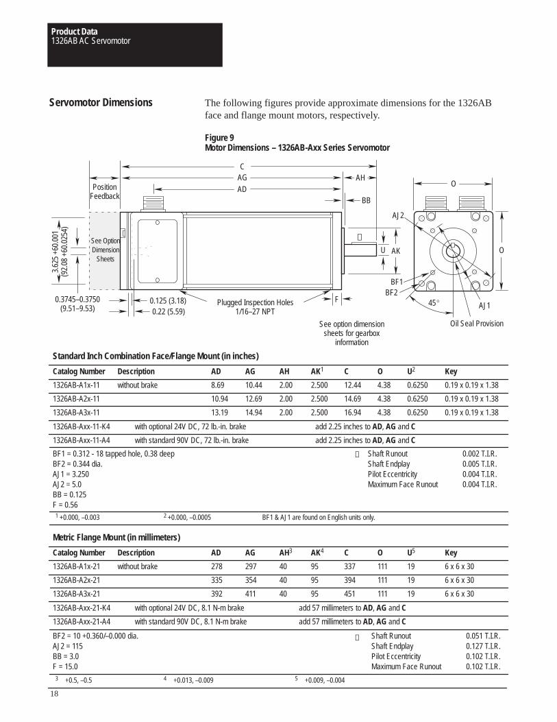
Servomotor Dimensions The following figures provide approximate dimensions for the 1326ABface and flange mount motors, respectively.
Figure 9Motor Dimensions – 1326AB-Axx Series Servomotor
Catalog Number
1326AB-A1x-11
1326AB-A2x-11
1326AB-A3x-11
AG
10.44
12.69
14.94
AD
8.69
10.94
13.19
AH
2.00
2.00
2.00
AK1
2.500
2.500
2.500
C
12.44
14.69
16.94
O
4.38
4.38
4.38
Key
0.19 x 0.19 x 1.38
0.19 x 0.19 x 1.38
0.19 x 0.19 x 1.38
BF1 = 0.312 - 18 tapped hole, 0.38 deepBF2 = 0.344 dia.AJ1 = 3.250AJ2 = 5.0BB = 0.125F = 0.561 +0.000, –0.003 2 +0.000, –0.0005 BF1 & AJ1 are found on English units only.
Standard Inch Combination Face/Flange Mount (in inches)
1326AB-Axx-11-K4 with optional 24V DC, 72 lb.-in. brake add 2.25 inches to AD, AG and C
1326AB-Axx-11-A4 with standard 90V DC, 72 lb.-in. brake add 2.25 inches to AD, AG and C
U2
0.6250
0.6250
0.6250
Description
without brake
Shaft Runout 0.002 T.I.R.Shaft Endplay 0.005 T.I.R.Pilot Eccentricity 0.004 T.I.R.Maximum Face Runout 0.004 T.I.R.
Catalog Number
1326AB-A1x-21
1326AB-A2x-21
1326AB-A3x-21
AG
297
354
411
AD
278
335
392
AH3
40
40
40
AK4
95
95
95
C
337
394
451
O
111
111
111
Key
6 x 6 x 30
6 x 6 x 30
6 x 6 x 30
BF2 = 10 +0.360/–0.000 dia.AJ2 = 115BB = 3.0F = 15.03 +0.5, –0.5 4 +0.013, –0.009 5 +0.009, –0.004
Metric Flange Mount (in millimeters)
1326AB-Axx-21-K4 with optional 24V DC, 8.1 N-m brake add 57 millimeters to AD, AG and C
1326AB-Axx-21-A4 with standard 90V DC, 8.1 N-m brake add 57 millimeters to AD, AG and C
U5
19
19
19
Description
without brake
Shaft Runout 0.051 T.I.R.Shaft Endplay 0.127 T.I.R.Pilot Eccentricity 0.102 T.I.R.Maximum Face Runout 0.102 T.I.R.
①
See option dimensionsheets for gearbox
information
ADAGC
F
AH
BB
0.125 (3.18)0.22 (5.59)
3.62
5 +6
0.00
1(9
2.08
+60
.025
4)
0.3745–0.3750(9.51–9.53)
PositionFeedback
Plugged Inspection Holes1/16–27 NPT
U AKSee OptionDimension
Sheets
O
O
BF1BF2
AJ1
AJ2
Oil Seal Provision
45�
①
①

Product Data1326AB AC Servomotor
19
Figure 10Motor Dimensions – 1326AB-Bxx Series Servomotor
Catalog Number
1326AB-B1x-11
1326AB-B2x-11
1326AB-B3x-11
1326AB-B4x-11
AG
11.78
14.78
18.03
21.28
AD
10.16
13.16
16.41
19.66
AH
2.38
2.38
2.38
2.38
AK1
4.50
4.50
4.50
4.50
C
14.16
17.16
20.41
23.66
O
5.88
5.88
5.88
5.88
Key
0.25 x 0.25 x 1.50
0.25 x 0.25 x 1.50
0.25 x 0.25 x 1.50
0.25 x 0.25 x 1.50
BF1 = 0.375 - 16 tapped hole, 0.38 deepBF2 = 0.406 dia.AJ1 = 5.875AJ2 = 7.0BB = 0.093F = 0.661 +0.000, –0.003 2 +0.000, –0.0005 BF1 & AJ1 are found on English units only.
Standard Inch Combination Face/Flange Mount (in inches)
1326AB-Bxx-11-K5 with optional 24V DC, 120 lb.-in. brake add 2.25 inches to AD, AG and C
1326AB-Bxx-11-A5 with standard 90V DC, 120 lb.-in. brake add 2.25 inches to AD, AG and C
U2
1.1250
1.1250
1.1250
1.1250
Description
without brake
Shaft Runout 0.002 T.I.R.Shaft Endplay 0.005 T.I.R.Pilot Eccentricity 0.004 T.I.R.Maximum Face Runout 0.004 T.I.R.
Catalog Number
1326AB-B1x-21
1326AB-B2x-21
1326AB-B3x-21
1326AB-B4x-21
AG
298
374
457
540
AD
257
333
416
498
AH3
50
50
50
50
AK4
130
130
130
130
C
348
424
507
589
O
149
149
149
149
Key
8 x 7 x 40
8 x 7 x 40
8 x 7 x 40
8 x 7 x 40
BF2 = 12 +0.430/–0.000 dia.AJ2 = 165BB = 4.0F = 16.03 +0.5, –0.5 4 +0.014, –0.011 5 +0.009, –0.004
Metric Flange Mount (in millimeters)
1326AB-Axx-21-K5 with optional 24V DC, 13.6 N-m brake add 57 millimeters to AD, AG and C
1326AB-Axx-21-A5 with standard 90V DC, 13.6 N-m brake add 57 millimeters to AD, AG and C
U5
24
24
24
24
Description
without brake
Shaft Runout 0.051 T.I.R.Shaft Endplay 0.127 T.I.R.Pilot Eccentricity 0.102 T.I.R.Maximum Face Runout 0.102 T.I.R.
①
①
See option dimensionsheets for gearbox
information
ADAGC
AH
BB
0.125 (3.18)0.22 (5.59)
5.12
5 +6
0.00
1(1
30.1
8 +6
0.02
54)
0.3745–0.3750(9.51–9.53)
PositionFeedback
U AK
See OptionDimension
Sheets
O
O
BF1
BF2
AJ1AJ2
Oil Seal Provision
FPlugged Inspection Holes
1/16–27 NPT
45°
①
Product Data1326AB AC Servomotor
20
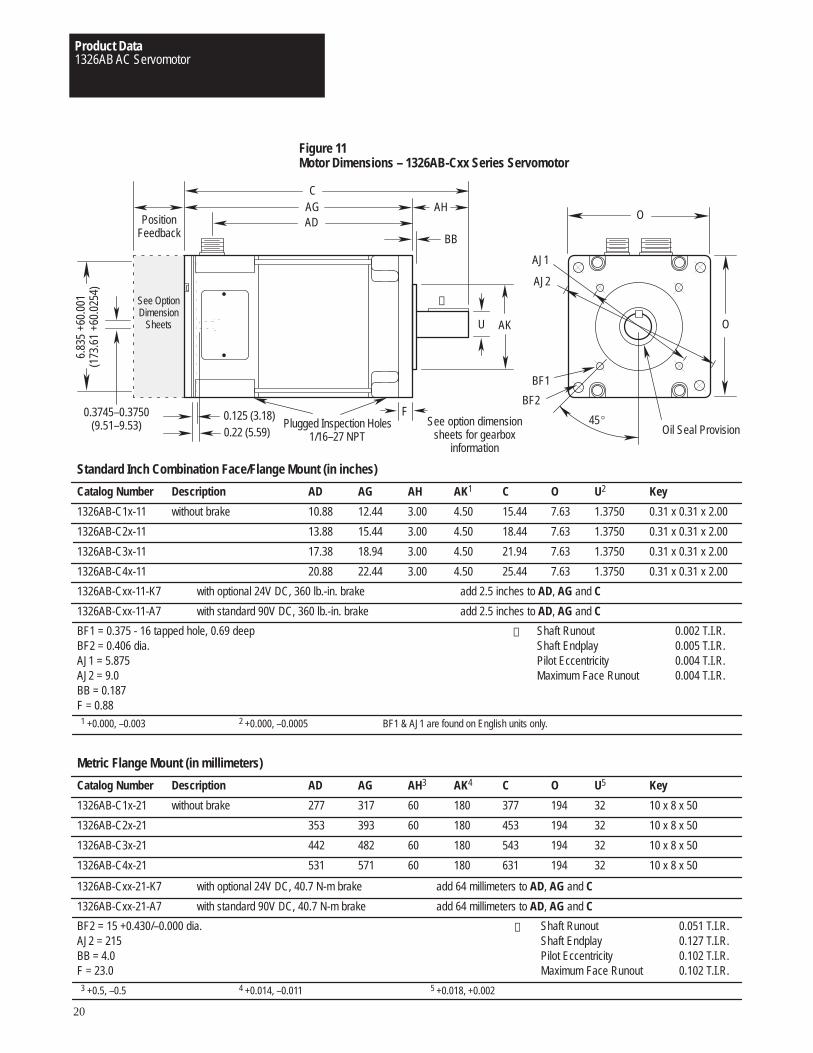
Figure 11Motor Dimensions – 1326AB-Cxx Series Servomotor
Catalog Number
1326AB-C1x-11
1326AB-C2x-11
1326AB-C3x-11
1326AB-C4x-11
AG
12.44
15.44
18.94
22.44
AD
10.88
13.88
17.38
20.88
AH
3.00
3.00
3.00
3.00
AK1
4.50
4.50
4.50
4.50
C
15.44
18.44
21.94
25.44
O
7.63
7.63
7.63
7.63
Key
0.31 x 0.31 x 2.00
0.31 x 0.31 x 2.00
0.31 x 0.31 x 2.00
0.31 x 0.31 x 2.00
BF1 = 0.375 - 16 tapped hole, 0.69 deepBF2 = 0.406 dia.AJ1 = 5.875AJ2 = 9.0BB = 0.187F = 0.881 +0.000, –0.003 2 +0.000, –0.0005 BF1 & AJ1 are found on English units only.
Standard Inch Combination Face/Flange Mount (in inches)
1326AB-Cxx-11-K7 with optional 24V DC, 360 lb.-in. brake add 2.5 inches to AD, AG and C
1326AB-Cxx-11-A7 with standard 90V DC, 360 lb.-in. brake add 2.5 inches to AD, AG and C
U2
1.3750
1.3750
1.3750
1.3750
Description
without brake
Shaft Runout 0.002 T.I.R.Shaft Endplay 0.005 T.I.R.Pilot Eccentricity 0.004 T.I.R.Maximum Face Runout 0.004 T.I.R.
Catalog Number
1326AB-C1x-21
1326AB-C2x-21
1326AB-C3x-21
1326AB-C4x-21
AG
317
393
482
571
AD
277
353
442
531
AH3
60
60
60
60
AK4
180
180
180
180
C
377
453
543
631
O
194
194
194
194
Key
10 x 8 x 50
10 x 8 x 50
10 x 8 x 50
10 x 8 x 50
BF2 = 15 +0.430/–0.000 dia.AJ2 = 215BB = 4.0F = 23.03 +0.5, –0.5 4 +0.014, –0.011 5 +0.018, +0.002
Metric Flange Mount (in millimeters)
1326AB-Cxx-21-K7 with optional 24V DC, 40.7 N-m brake add 64 millimeters to AD, AG and C
1326AB-Cxx-21-A7 with standard 90V DC, 40.7 N-m brake add 64 millimeters to AD, AG and C
U5
32
32
32
32
Description
without brake
Shaft Runout 0.051 T.I.R.Shaft Endplay 0.127 T.I.R.Pilot Eccentricity 0.102 T.I.R.Maximum Face Runout 0.102 T.I.R.
See option dimensionsheets for gearbox
information
①
①
See OptionDimension
Sheets
ADAGC
AH
BB
0.125 (3.18)0.22 (5.59)
6.83
5 +6
0.00
1(1
73.6
1 +6
0.02
54)
0.3745–0.3750(9.51–9.53)
PositionFeedback
U AK
O
O
BF1
BF2
AJ1
AJ2
Oil Seal Provision
FPlugged Inspection Holes
1/16–27 NPT45�
①
Product Data1326AB AC Servomotor
21
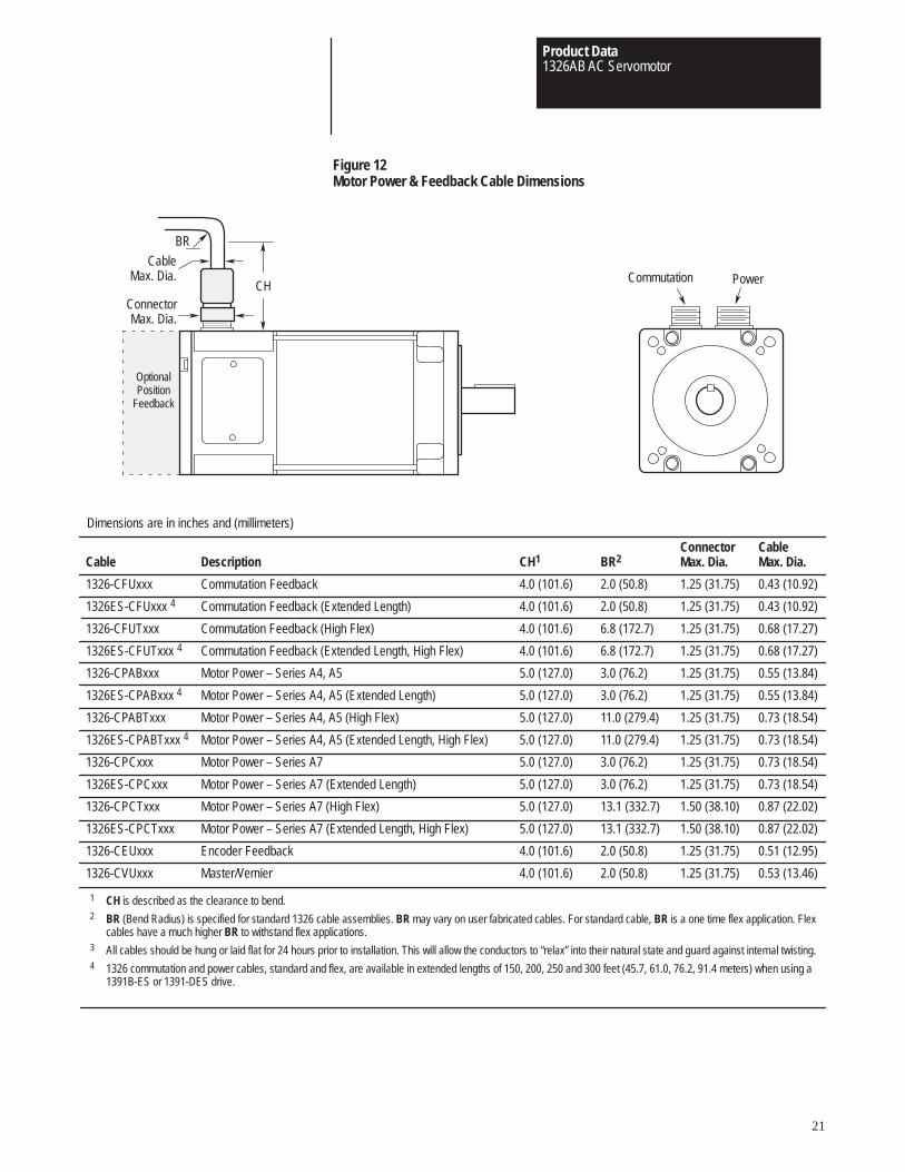
Figure 12Motor Power & Feedback Cable Dimensions
Cable
1326-CFUxxx
1326ES-CFUxxx 4
1326-CFUTxxx
1326ES-CFUTxxx 4
1326-CPABxxx
1326ES-CPABxxx 4
1326-CPABTxxx
1326ES-CPABTxxx 4
1326-CPCxxx
1326ES-CPCxxx
1326-CPCTxxx
1326ES-CPCTxxx
1326-CEUxxx
1326-CVUxxx
BR2
2.0 (50.8)
2.0 (50.8)
6.8 (172.7)
6.8 (172.7)
3.0 (76.2)
3.0 (76.2)
11.0 (279.4)
11.0 (279.4)
3.0 (76.2)
3.0 (76.2)
13.1 (332.7)
13.1 (332.7)
2.0 (50.8)
2.0 (50.8)
CH1
4.0 (101.6)
4.0 (101.6)
4.0 (101.6)
4.0 (101.6)
5.0 (127.0)
5.0 (127.0)
5.0 (127.0)
5.0 (127.0)
5.0 (127.0)
5.0 (127.0)
5.0 (127.0)
5.0 (127.0)
4.0 (101.6)
4.0 (101.6)
ConnectorMax. Dia.
1.25 (31.75)
1.25 (31.75)
1.25 (31.75)
1.25 (31.75)
1.25 (31.75)
1.25 (31.75)
1.25 (31.75)
1.25 (31.75)
1.25 (31.75)
1.25 (31.75)
1.50 (38.10)
1.50 (38.10)
1.25 (31.75)
1.25 (31.75)
CableMax. Dia.
0.43 (10.92)
0.43 (10.92)
0.68 (17.27)
0.68 (17.27)
0.55 (13.84)
0.55 (13.84)
0.73 (18.54)
0.73 (18.54)
0.73 (18.54)
0.73 (18.54)
0.87 (22.02)
0.87 (22.02)
0.51 (12.95)
0.53 (13.46)
1 CH is described as the clearance to bend.2 BR (Bend Radius) is specified for standard 1326 cable assemblies. BR may vary on user fabricated cables. For standard cable, BR is a one time flex application. Flex
cables have a much higher BR to withstand flex applications.3 All cables should be hung or laid flat for 24 hours prior to installation. This will allow the conductors to “relax” into their natural state and guard against internal twisting.4 1326 commutation and power cables, standard and flex, are available in extended lengths of 150, 200, 250 and 300 feet (45.7, 61.0, 76.2, 91.4 meters) when using a
1391B-ES or 1391-DES drive.
Description
Commutation Feedback
Commutation Feedback (Extended Length)
Commutation Feedback (High Flex)
Commutation Feedback (Extended Length, High Flex)
Motor Power – Series A4, A5
Motor Power – Series A4, A5 (Extended Length)
Motor Power – Series A4, A5 (High Flex)
Motor Power – Series A4, A5 (Extended Length, High Flex)
Motor Power – Series A7
Motor Power – Series A7 (Extended Length)
Motor Power – Series A7 (High Flex)
Motor Power – Series A7 (Extended Length, High Flex)
Encoder Feedback
Master/Vernier
Dimensions are in inches and (millimeters)
OptionalPosition
Feedback
ConnectorMax. Dia.
CableMax. Dia.
BR
CHCommutation Power
Product Data1326AB AC Servomotor
22
Servomotor Options This section provides detailed information on the various options availablefor the 1326 AC Servomotor.
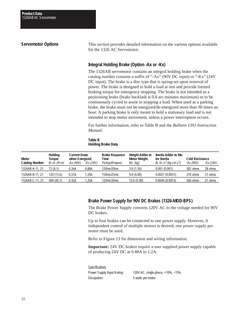
Integral Holding Brake (Option -Ax or -Kx)The 1326AB servomotor contains an integral holding brake when thecatalog number contains a suffix of “-Ax” (90V DC input) or “-Kx” (24VDC input). The brake is a disc type that is spring-set upon removal ofpower. The brake is designed to hold a load at rest and provide limitedbraking torque for emergency stopping. The brake is not intended as apositioning brake (brake backlash is 0.8 arc-minutes maximum) or to becontinuously cycled to assist in stopping a load. When used as a parkingbrake, the brake must not be energized/de-energized more than 90 times anhour. A parking brake is only meant to hold a stationary load and is notintended to stop motor movement, unless a power interruption occurs.
For further information, refer to Table B and the Bulletin 1391 InstructionManual.
Table BHolding Brake Data
MotorCatalog Number
1326AB-A-11, 21
1326AB-B-11, 21
1326AB-C-11, 21
HoldingTorquelb.-in. (N-m)
72 (8.1)
120 (13.6)
400 (45.1)
Current Drawwhen Energized
Brake ResponseTimePickup/Dropout
120ms/20ms
150ms/25ms
120ms/30ms
Weight Adder toMotor Weightlbs. (kg)
3.0 (1.36)
9.0 (4.08)
13.0 (5.90)
Cold ResistanceInertia Adder to Mo-tor Inertialb.-in.-s2 (kg-cm-s2)
0.001 (0.001)
0.0027 (0.0031)
0.0046 (0.0053)
-Ax (90V)
0.26A
0.37A
0.32A
-Kx (24V)
0.88A
1.20A
1.20A
-Ax (90V)
382 ohms
270 ohms
306 ohms
-Kx (24V)
28 ohms
21 ohms
21 ohms
Brake Power Supply for 90V DC Brakes (1326-MOD-BPS)The Brake Power Supply converts 120V AC to the voltage needed for 90VDC brakes.
Up to four brakes can be connected to one power supply. However, ifindependent control of multiple motors is desired, one power supply permotor must be used.
Refer to Figure 13 for dimension and wiring information.
Important: 24V DC brakes require a user supplied power supply capableof producing 24V DC at 0.88A to 1.2A.
Specifications
Power Supply Input Rating: 120V AC, single-phase, +10%, –15%
Dissipation: 5 watts per motor
Product Data1326AB AC Servomotor
23
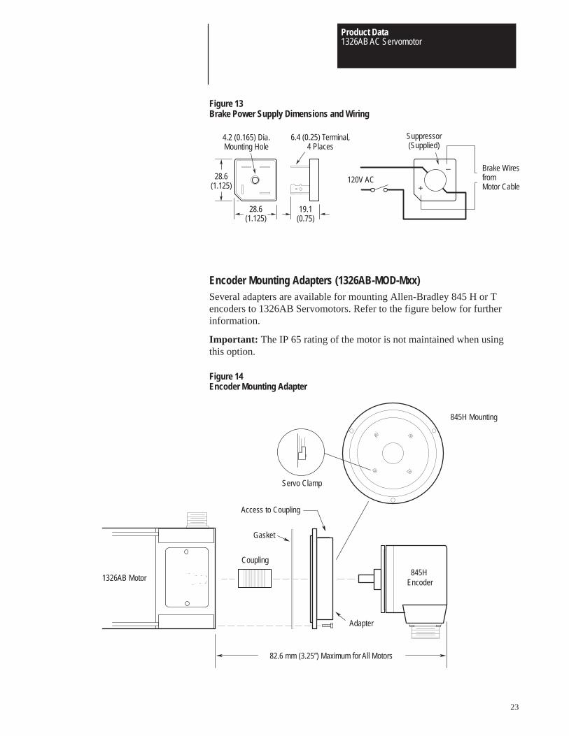
Figure 13Brake Power Supply Dimensions and Wiring
28.6(1.125)
28.6(1.125)
4.2 (0.165) Dia.Mounting Hole
6.4 (0.25) Terminal,4 Places
19.1(0.75)
+
Suppressor(Supplied)
Brake Wiresfrom Motor Cable
120V AC–
Encoder Mounting Adapters (1326AB-MOD-Mxx)Several adapters are available for mounting Allen-Bradley 845 H or Tencoders to 1326AB Servomotors. Refer to the figure below for furtherinformation.
Important: The IP 65 rating of the motor is not maintained when usingthis option.
Figure 14Encoder Mounting Adapter
845H Encoder
845H Mounting
Servo Clamp
Gasket
Access to Coupling
1326AB Motor
Coupling
82.6 mm (3.25”) Maximum for All Motors
Adapter
Product Data1326AB AC Servomotor
24
Shaft Oil Seal (1326AB-MOD-SSV-xx)A Viton shaft oil seal is available for field installation on the motor shaft.The seal is to be used in applications where the motor shaft may besubjected to occasional oil splashes (motor is mounted to gearbox, etc.).The kit is not intended to be used in applications where the motor shaft ispartially or fully submerged in oil.
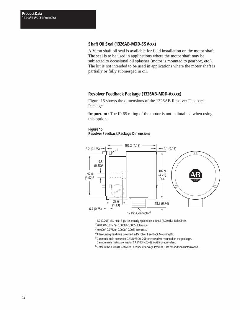
Resolver Feedback Package (1326AB-MOD-Vxxxx)Figure 15 shows the dimensions of the 1326AB Resolver FeedbackPackage.
Important: The IP 65 rating of the motor is not maintained when usingthis option.
Figure 15Resolver Feedback Package Dimensions
106.2 (4.18)3.2 (0.125) 4.1 (0.16)
107.9(4.25)Dia.
18.8 (0.74)28.6(1.13)
6.4 (0.25)
9.5
92.0
1
5.2 (0.206) dia. hole, 3 places equally spaced on a 101.6 (4.00) dia. Bolt Circle.1
+0.000/–0.0127 (+0.0000/–0.0005) tolerance.2
+0.000/–0.0762 (+0.0000/–0.003) tolerance.3
All mounting hardware provided in Resolver Feedback Mounting Kit.4
Cannon female connector CA3102R20–29P or equivalent mounted on the package.Cannon male mating connector CA3106F–20–295–A95 or equivalent.
5
Refer to the 1326AB Resolver Feedback Package Product Data for additional information.6
(0.38)2
(3.62)3
17 Pin Connector5
Product Data1326AB AC Servomotor
25
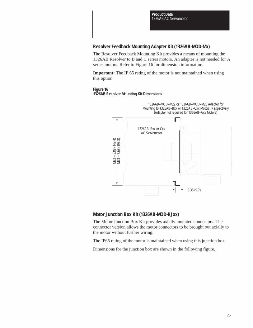
Resolver Feedback Mounting Adapter Kit (1326AB-MOD-Mx)The Resolver Feedback Mounting Kit provides a means of mounting the1326AB Resolver to B and C series motors. An adapter is not needed for Aseries motors. Refer to Figure 16 for dimension information.
Important: The IP 65 rating of the motor is not maintained when usingthis option.
Figure 161326AB Resolver Mounting Kit Dimensions
1326AB–Bxx or CxxAC Servomotor
M22
– 5
.88
(149
.4)
M23
– 7
.63
(193
.8)
1326AB–MOD–M22 or 1326AB–MOD–M23 Adapter forMounting to 1326AB–Bxx or 1326AB–Cxx Motors, Respectively
(Adaptor not required for 1326AB–Axx Motors)
0.38 (9.7)
Motor Junction Box Kit (1326AB-MOD-RJxx)The Motor Junction Box Kit provides axially mounted connectors. Theconnector version allows the motor connectors to be brought out axially tothe motor without further wiring.
The IP65 rating of the motor is maintained when using this junction box.
Dimensions for the junction box are shown in the following figure.

Product Data1326AB AC Servomotor
26
Figure 17Motor Junction Box Dimensions
Dimension
A
B
C
withConnectors
4.13 (105.0)
2.44 (62.0)
2.50 (190.5)
Alternate Position
Cover and Gasket
Gasket
C A
B
Blower Kits (1326AB-MOD-G3, G4)Two blower kits are available for use with 1326AB “C” Series ACServomotors. The “G3” kit is designed for the “C2E” and “C4B”servomotors. The continuous current rating of all other “C” frame motorsis too high to gain the benefit of the blower kit. The “G3” will not work onmotors with a rear mounted encoder. The “G4” kit is designed for the“C4B” motor only. Each kit consists of an impedance protected fan (ULrecognized, CSA approved), housing, grill guard and necessary hardware.
Important: The IP 65 rating of the motor is not maintained when usingthis option.
Specifications
Input Voltage 220/240V AC, 50/60 Hz., single-phase
Line Amperes 0.15 / 0.14
Locked Rotor Amperes 0.23 / 0.23
Fan Output 240 CFM
Air Inlet Clearance 6 inches (152.4 mm)
Weight 4 lbs. (1.81 kg)
The following table illustrates the operational improvements realized whenthe blower kit is installed on the motors shown. Refer to Figure 18 fordimensions.

Product Data1326AB AC Servomotor
27
Table CPerformance Improvements with the Blower Kit
Motor CatalogNumber
1326AB-C2E3
1326AB-C4B4
RMS Cont.Torque1
lb.-in. (N-m)
210 (23.7)
420 (47.5)
ContinuousAmperesA
33.2
38.2
RMS Cont.Torque1
lb.-in. (N-m)
285 (32.2)
505 (57.1)
ContinuousAmperes2
A
45.0
45.0
Motor without Blower Motor with Blower
1 at 40° C ambient.2 Amplifier available current may limit actual torque improvement. Continuous output cannot exceed 45A.3 Works with G3 option only.4 Works with G3 and G4 option.
Figure 18Blower Kit Dimensions
17.5 (445.0)
11.0(279.0)
Blower Housing
Connect to 240V AC,Single–Phase,
50/60 Hz.
4.66 (118.4)
9.25(235.0)
6.75(171.5)
1.75 (44.5)
1326AB ACServomotor
Top View
0.875 (22.2) dia. knockout with0.5 (12.7) provision 4 sides.Conduit box with two 18 (457.2)19 ga. stranded flying leads inside.
1326AB–MOD–G3
1326AB–MOD–G4
Product Data1326AB AC Servomotor
28
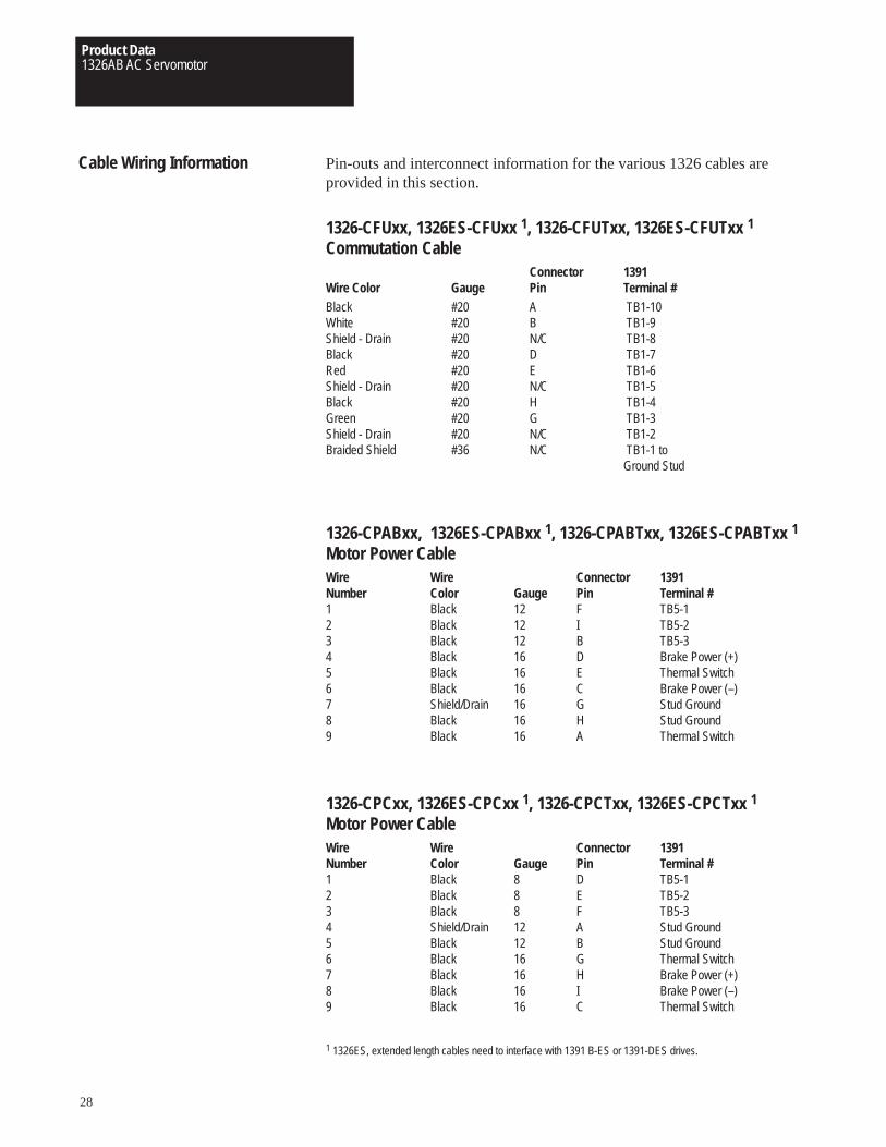
Cable Wiring Information Pin-outs and interconnect information for the various 1326 cables areprovided in this section.
1326-CFUxx, 1326ES-CFUxx 1, 1326-CFUTxx, 1326ES-CFUTxx 1
Commutation CableConnector 1391
Wire Color Gauge Pin Terminal #Black #20 A TB1-10White #20 B TB1-9Shield - Drain #20 N/C TB1-8Black #20 D TB1-7Red #20 E TB1-6Shield - Drain #20 N/C TB1-5Black #20 H TB1-4Green #20 G TB1-3Shield - Drain #20 N/C TB1-2Braided Shield #36 N/C TB1-1 to
Ground Stud
1326-CPABxx, 1326ES-CPABxx 1, 1326-CPABTxx, 1326ES-CPABTxx 1
Motor Power CableWire Wire Connector 1391Number Color Gauge Pin Terminal #1 Black 12 F TB5-12 Black 12 I TB5-23 Black 12 B TB5-34 Black 16 D Brake Power (+)5 Black 16 E Thermal Switch6 Black 16 C Brake Power (–)7 Shield/Drain 16 G Stud Ground8 Black 16 H Stud Ground9 Black 16 A Thermal Switch
1326-CPCxx, 1326ES-CPCxx 1, 1326-CPCTxx, 1326ES-CPCTxx 1 Motor Power CableWire Wire Connector 1391Number Color Gauge Pin Terminal #1 Black 8 D TB5-12 Black 8 E TB5-23 Black 8 F TB5-34 Shield/Drain 12 A Stud Ground5 Black 12 B Stud Ground6 Black 16 G Thermal Switch7 Black 16 H Brake Power (+)8 Black 16 I Brake Power (–)9 Black 16 C Thermal Switch
1 1326ES, extended length cables need to interface with 1391 B-ES or 1391-DES drives.
Product Data1326AB AC Servomotor
29
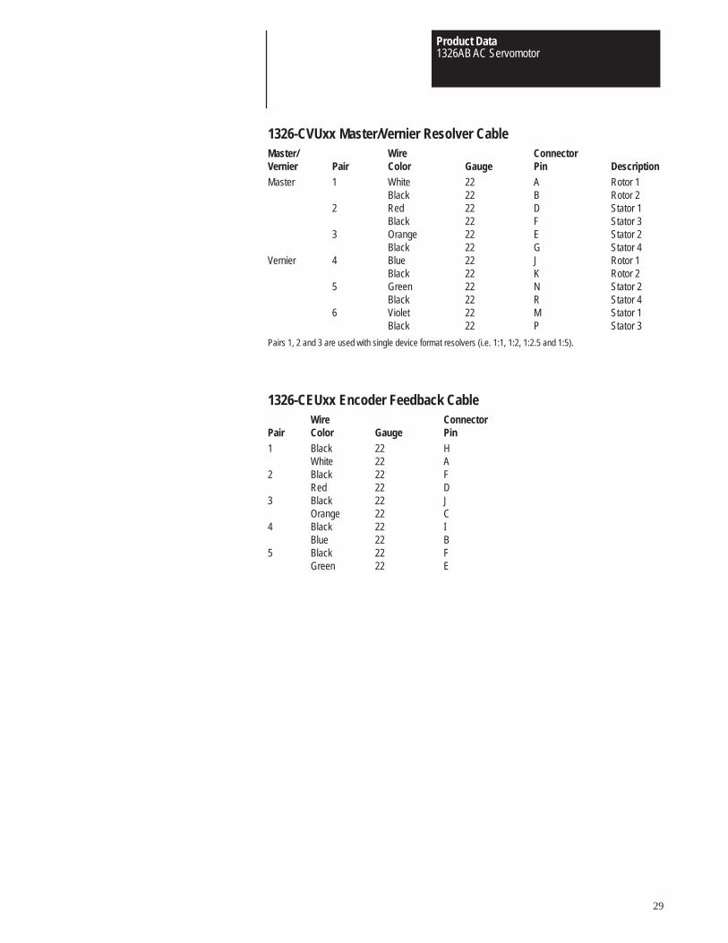
1326-CVUxx Master/Vernier Resolver CableMaster/ Wire ConnectorVernier Pair Color Gauge Pin DescriptionMaster 1 White 22 A Rotor 1
Black 22 B Rotor 22 Red 22 D Stator 1
Black 22 F Stator 33 Orange 22 E Stator 2
Black 22 G Stator 4Vernier 4 Blue 22 J Rotor 1
Black 22 K Rotor 25 Green 22 N Stator 2
Black 22 R Stator 46 Violet 22 M Stator 1
Black 22 P Stator 3
Pairs 1, 2 and 3 are used with single device format resolvers (i.e. 1:1, 1:2, 1:2.5 and 1:5).
1326-CEUxx Encoder Feedback CableWire Connector
Pair Color Gauge Pin1 Black 22 H
White 22 A2 Black 22 F
Red 22 D3 Black 22 J
Orange 22 C4 Black 22 I
Blue 22 B5 Black 22 F
Green 22 E
Product Data1326AB AC Servomotor
30
Servomotor Application Guide The following steps are a general guide designed to assist in servomotorselection. Formulas provided on the following pages should be used inconjunction with the steps below to determine correct motor sizing. Forfurther assistance, complete the appropriate Application Data Sheet(pages 38-43) and contact your local Allen-Bradley Sales Office.
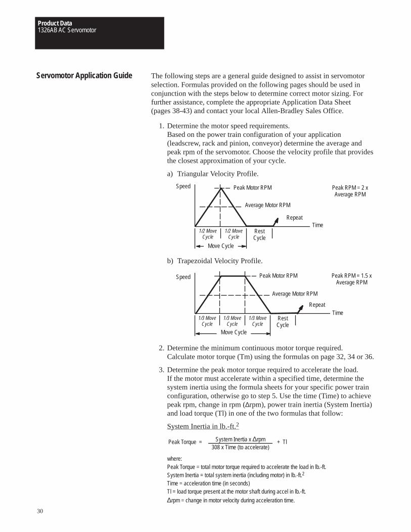
1. Determine the motor speed requirements.Based on the power train configuration of your application(leadscrew, rack and pinion, conveyor) determine the average andpeak rpm of the servomotor. Choose the velocity profile that providesthe closest approximation of your cycle.
a) Triangular Velocity Profile.
1/2 MoveCycle
Peak Motor RPM
Average Motor RPM
1/2 MoveCycle
RestCycle
Repeat
Move Cycle
Time
Speed Peak RPM = 2 xAverage RPM
b) Trapezoidal Velocity Profile.
1/3 MoveCycle
Peak Motor RPM
Average Motor RPM
RestCycle
Repeat
Move Cycle
Time
Speed
1/3 MoveCycle
1/3 MoveCycle
Peak RPM = 1.5 xAverage RPM
2. Determine the minimum continuous motor torque required.Calculate motor torque (Tm) using the formulas on page 32, 34 or 36.
3. Determine the peak motor torque required to accelerate the load.If the motor must accelerate within a specified time, determine thesystem inertia using the formula sheets for your specific power trainconfiguration, otherwise go to step 5. Use the time (Time) to achievepeak rpm, change in rpm (∆rpm), power train inertia (System Inertia)and load torque (Tl) in one of the two formulas that follow:
System Inertia in lb.-ft.2
Peak Torque = System Inertia x ∆rpm308 x Time (to accelerate)
+ Tl
where:Peak Torque = total motor torque required to accelerate the load in lb.-ft.System Inertia = total system inertia (including motor) in lb.-ft.2
Time = acceleration time (in seconds)Tl = load torque present at the motor shaft during accel in lb.-ft.
∆rpm = change in motor velocity during acceleration time.
Product Data1326AB AC Servomotor
31
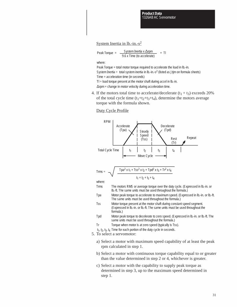
System Inertia in lb.-in.-s2
Peak Torque = System Inertia x ∆rpm9.6 x Time (to accelerate)
+ Tl
where:Peak Torque = total motor torque required to accelerate the load in lb.-in.System Inertia = total system inertia in lb.-in.-s2 (listed as Jtjm on formula sheets)Time = acceleration time (in seconds)Tl = load torque present at the motor shaft during accel in lb.-in.
∆rpm = change in motor velocity during acceleration time.
4. If the motors total time to accelerate/decelerate (t1 + t3) exceeds 20%of the total cycle time (t1+t2+t3+t4), determine the motors averagetorque with the formula shown.
Duty Cycle Profile
Decelerate(Tpd)
Accelerate(Tpa)
Repeat
Move Cycle
RPM
SteadySpeed(Tss) Rest
(Tr)
Total Cycle Time t1 t2 t3 t4
where:Trms The motors RMS or average torque over the duty cycle. (Expressed in lb.-in. or
lb.-ft. The same units must be used throughout the formula.)Tpa Motor peak torque to accelerate to maximum speed. (Expressed in lb.-in. or lb.-ft.
The same units must be used throughout the formula.)Tss Motor torque present at the motor shaft during constant speed segment.
(Expressed in lb.-in. or lb.-ft. The same units must be used throughout theformula.)
Tpd Motor peak torque to decelerate to zero speed. (Expressed in lb.-in. or lb.-ft. Thesame units must be used throughout the formula.)
Tr Torque when motor is at zero speed (typically is Tss). t1, t2, t3, t4 Time for each portion of the duty cycle in seconds.
Tpa2 x t1 + Tss2 x t2 + Tpd2 x t3 + Tr2 x t4
t1 + t2 + t3 + t4
Trms =
5. To select a servomotor:
a) Select a motor with maximum speed capability of at least the peakrpm calculated in step 1.
b) Select a motor with continuous torque capability equal to or greaterthan the value determined in step 2 or 4, whichever is greater.
c) Select a motor with the capability to supply peak torque asdetermined in step 3, up to the maximum speed determined instep 1.

Product Data1326AB AC Servomotor
32
Servomotor Driven Leadscrew Formulas
PositionController
Motion ControlDrive TransmissionMotor
Nut
Position FeedbackDevice
Leadscrew
Table/Slide
Part/Tool
Motor Speed Nm = V1Lead
x G.R.
Continuous Torque at the Leadscrew Tb = W1 x u x Lead6.28 x e1
Thrust x Lead6.28 x e1
Thrust x Lead x u6.28 x e1
+ +
(1) (2) (3)
W1 x Lead6.28 x e1
+
(5)
sine θ
Continuous Motor Torque Tm = TbG.R. x e2
x 1.1
(4) (6)
Total System Inertia Jtjm = W1386
+ Jb( Lead6.28 )
2
x][ 1G.R.2
+ Jgb + Jm
Accelerating Torque See step 3 of the Servomotor Application Guide on page 30.
Where: Notes:e = Efficiency of leadscrew, e1 (90%
typical) or gearbox, e2 (95% typical).G.R. = Ratio of motor speed to leadscrew
speed.Jb = Leadscrew inertia (lb.-in.-s2).Jgb = Gearbox inertia at the motor shaft
(lb.-in.-s2).Jm = Motor inertia (lb.-in.-s2).Jtjm = Total system inertia at the motor
shaft (lb.-in.-s2).Lead = Movement of slide in inches per
revolution of leadscrew.Nm = Motor velocity (rpm).
Tb = Torque at leadscrew (lb.-in.).Thrust = Cutting force applied by slide/load on
a workpiece (lbs).Tl = Load torque present at the motor
shaft during accel (lb.-in.).Tm = Load torque required at the motor
(lb.-in.).u = Table/slide sliding coefficient of
friction (typically 0.03 to 0.2).V1 = Linear velocity of slide/load (IPM).W1 = Weight of slide and load (lbs.).
θ = Angle of leadscrew positionreferenced from the horizontal axis(0°).
(1) Friction torque generated by the weightof the table/slide and part/tool.
(2) Torque required for thrust (cutting force)load.
(3) Friction torque generated by the thrust(cutting force) load (approximation).
(4) Safety factor to account for torquerequired to overcome seals, gibadjustments, etc. (10% of Tm, min.).
(5) This term is for a non-counterbalanced,non-horizontal axis.
(6) System inertia should not exceed 5times the motor inertia.
Product Data1326AB AC Servomotor
33
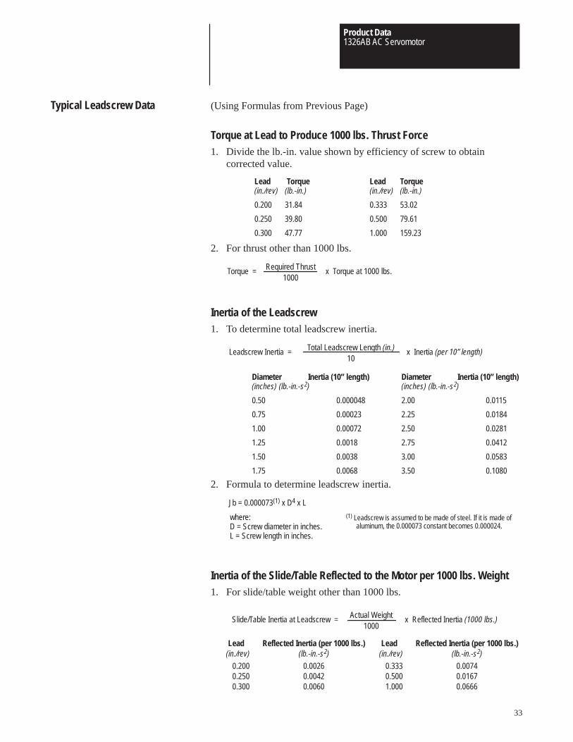
Typical Leadscrew Data (Using Formulas from Previous Page)
Torque at Lead to Produce 1000 lbs. Thrust Force1. Divide the lb.-in. value shown by efficiency of screw to obtain
corrected value.
Lead Torque(in./rev) (lb.-in.)
0.200 31.84
0.250 39.80
0.300 47.77
Lead Torque(in./rev) (lb.-in.)
0.333 53.02
0.500 79.61
1.000 159.23
2. For thrust other than 1000 lbs.
Torque = Required Thrust1000
x Torque at 1000 lbs.
Inertia of the Leadscrew1. To determine total leadscrew inertia.
Leadscrew Inertia = Total Leadscrew Length (in.)10
x Inertia (per 10” length)
Diameter Inertia (10” length)(inches) (lb.-in.-s2)
0.50 0.000048
0.75 0.00023
1.00 0.00072
1.25 0.0018
1.50 0.0038
1.75 0.0068
Diameter Inertia (10” length)(inches) (lb.-in.-s2)
2.00 0.0115
2.25 0.0184
2.50 0.0281
2.75 0.0412
3.00 0.0583
3.50 0.1080
2. Formula to determine leadscrew inertia.
Jb = 0.000073(1) x D4 x L
where:D = Screw diameter in inches.L = Screw length in inches.
(1) Leadscrew is assumed to be made of steel. If it is made ofaluminum, the 0.000073 constant becomes 0.000024.
Inertia of the Slide/Table Reflected to the Motor per 1000 lbs. Weight1. For slide/table weight other than 1000 lbs.
Slide/Table Inertia at Leadscrew = Actual Weight1000
x Reflected Inertia (1000 lbs.)
Lead Reflected Inertia (per 1000 lbs.)(in./rev) (lb.-in.-s2)
0.200 0.00260.250 0.00420.300 0.0060
Lead Reflected Inertia (per 1000 lbs.)(in./rev) (lb.-in.-s2)
0.333 0.00740.500 0.01671.000 0.0666
Product Data1326AB AC Servomotor
34
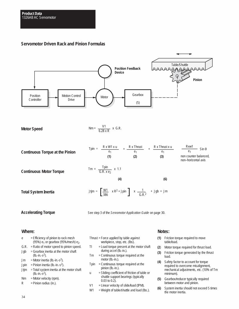
Servomotor Driven Rack and Pinion Formulas
PositionController
Motion ControlDrive
Gearbox
(5)
Motor
Position FeedbackDevice
Pinion
Table/Shuttle
Motor Speed Nm = V16.28 x R
x G.R.
Continuous Torque at the PinionRxw1
e1Tpin = R x W1 x u
e1
R x Thruste1
R x Thrust x ue1
+ +
(1) (2) (3)
Sin θ
non counter balanced,non–horizontal axis
Continuous Motor TorqueTm = Tpin
G.R. x e2 x 1.1
(4) (6)
Total System Inertia Jtjm = W1386
x R2 + Jpin x][ 1G.R.2
+ Jgb + Jm
Accelerating Torque See step 3 of the Servomotor Application Guide on page 30.
Where: Notes:e = Efficiency of pinion to rack mesh
(95%) e1 or gearbox (95%/mesh) e2.G.R. = Ratio of motor speed to pinion speed.Jgb = Gearbox inertia at the motor shaft
(lb.-in.-s2).Jm = Motor inertia (lb.-in.-s2).Jpin = Pinion inertia (lb.-in.-s2).Jtjm = Total system inertia at the motor shaft
(lb.-in.-s2).Nm = Motor velocity (rpm).R = Pinion radius (in.).
Thrust = Force applied by table againstworkpiece, stop, etc. (lbs).
Tl = Load torque present at the motor shaftduring accel (lb.-in.).
Tm = Continuous torque required at themotor (lb.-in.).
Tpin = Continuous torque required at thepinion (lb.-in.).
u = Sliding coefficient of friction of table orshuttle support bearings (typically0.03 to 0.2).
V1 = Linear velocity of slide/load (IPM).W1 = Weight of table/shuttle and load (lbs.).
(1) Friction torque required to movetable/load.
(2) Motor torque required for thrust load.
(3) Friction torque generated by the thrustload.
(4) Safety factor to account for torquerequired to overcome misalignment,mechanical adjustments, etc. (10% of Tmminimum).
(5) Gearbox/reducer typically requiredbetween motor and pinion.
(6) System inertia should not exceed 5 timesthe motor inertia.
Product Data1326AB AC Servomotor
35
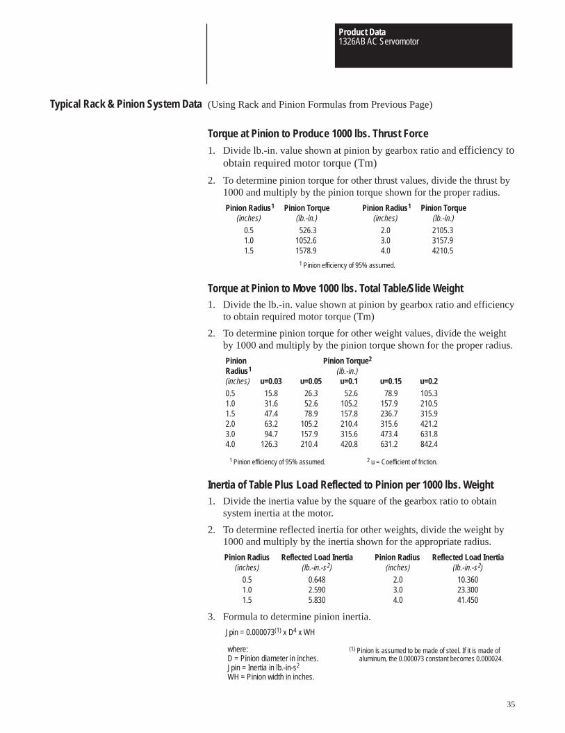
Typical Rack & Pinion System Data (Using Rack and Pinion Formulas from Previous Page)
Torque at Pinion to Produce 1000 lbs. Thrust Force1. Divide lb.-in. value shown at pinion by gearbox ratio and efficiency to
obtain required motor torque (Tm)
2. To determine pinion torque for other thrust values, divide the thrust by1000 and multiply by the pinion torque shown for the proper radius.
Pinion Radius1 Pinion Torque(inches) (lb.-in.)
0.5 526.31.0 1052.61.5 1578.9
1 Pinion efficiency of 95% assumed.
Pinion Radius1 Pinion Torque(inches) (lb.-in.)
2.0 2105.33.0 3157.94.0 4210.5
Torque at Pinion to Move 1000 lbs. Total Table/Slide Weight1. Divide the lb.-in. value shown at pinion by gearbox ratio and efficiency
to obtain required motor torque (Tm)
2. To determine pinion torque for other weight values, divide the weightby 1000 and multiply by the pinion torque shown for the proper radius.
Pinion Pinion Torque2
Radius1 (lb.-in.)(inches) u=0.03 u=0.05 u=0.1 u=0.15 u=0.20.5 15.8 26.3 52.6 78.9 105.31.0 31.6 52.6 105.2 157.9 210.51.5 47.4 78.9 157.8 236.7 315.92.0 63.2 105.2 210.4 315.6 421.23.0 94.7 157.9 315.6 473.4 631.84.0 126.3 210.4 420.8 631.2 842.4
1 Pinion efficiency of 95% assumed. 2 u = Coefficient of friction.
Inertia of Table Plus Load Reflected to Pinion per 1000 lbs. Weight1. Divide the inertia value by the square of the gearbox ratio to obtain
system inertia at the motor.
2. To determine reflected inertia for other weights, divide the weight by1000 and multiply by the inertia shown for the appropriate radius.
Pinion Radius Reflected Load Inertia(inches) (lb.-in.-s2)
0.5 0.6481.0 2.5901.5 5.830
Pinion Radius Reflected Load Inertia(inches) (lb.-in.-s2)
2.0 10.3603.0 23.3004.0 41.450
3. Formula to determine pinion inertia.
Jpin = 0.000073(1) x D4 x WH
where:D = Pinion diameter in inches.Jpin = Inertia in lb.-in-s2
WH = Pinion width in inches.
(1) Pinion is assumed to be made of steel. If it is made ofaluminum, the 0.000073 constant becomes 0.000024.
Product Data1326AB AC Servomotor
36
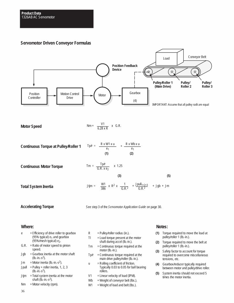
Servomotor Driven Conveyor Formulas
PositionController
Motion ControlDrive
Gearbox
(4)
Motor
Position FeedbackDevice
Conveyor BeltLoad
Pulley/Roller 1(Main Drive)
Pulley/Roller 2
Pulley/Roller 3
IMPORTANT: Assume that all pulley radii are equal
Motor Speed Nm = V16.28 x R
x G.R.
Continuous Torque at Pulley/Roller 1 Tp/r = R x W1 x ue1
R x Wb x ue1
+
(1) (2)
Continuous Motor Torque Tm = Tp/rG.R. x e2
x 1.25
(3) (5)
Total System Inertia Jtjm = W1386
x R2 x 1G.R.2
+ Jpull1+2+3G.R.2
+ Jgb + Jm
Accelerating Torque See step 3 of the Servomotor Application Guide on page 30.
Where: Notes:e = Efficiency of drive roller to gearbox
(95% typical) e1 and gearbox(95%/mesh typical) e2.
G.R. = Ratio of motor speed to pinionspeed.
Jgb = Gearbox inertia at the motor shaft(lb.-in.-s2).
Jm = Motor inertia (lb.-in.-s2).Jpull = Pulley + roller inertia, 1, 2, 3
(lb.-in.-s2).Jtjm = Total system inertia at the motor
shaft (lb.-in.-s2).Nm = Motor velocity (rpm).
R = Pulley/roller radius (in.).Tl = Load torque present at the motor
shaft during accel (lb.-in.).Tm = Continuous torque required at the
motor (lb.-in.).Tp/r = Continuous torque required at the
main drive pulley/roller (lb.-in.).u = Rolling coefficient of friction.
Typically 0.03 to 0.05 for ball bearingrollers.
V1 = Linear velocity of load (IPM).Wb = Weight of conveyor belt (lbs.).W1 = Weight of load and belt (lbs.).
(1) Torque required to move the load atpulley/roller 1 (lb.-in.).
(2) Torque required to move the belt atpulley/roller 1 (lb.-in.).
(3) Safety factor to account for torquerequired to overcome miscellaneoustensions, etc.
(4) Gearbox/reducer typically requiredbetween motor and pulley/drive roller.
(5) System inertia should not exceed 5times the motor inertia.
Product Data1326AB AC Servomotor
37
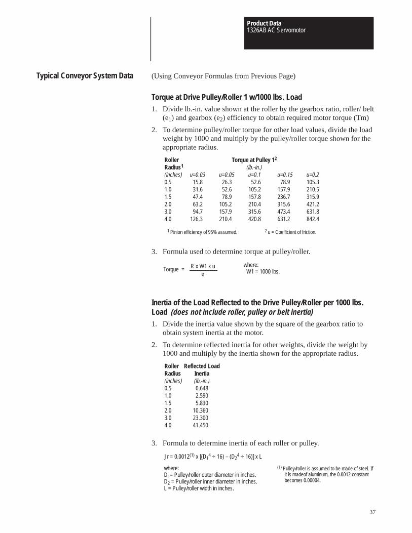
Typical Conveyor System Data (Using Conveyor Formulas from Previous Page)
Torque at Drive Pulley/Roller 1 w/1000 lbs. Load1. Divide lb.-in. value shown at the roller by the gearbox ratio, roller/ belt
(e1) and gearbox (e2) efficiency to obtain required motor torque (Tm)
2. To determine pulley/roller torque for other load values, divide the loadweight by 1000 and multiply by the pulley/roller torque shown for theappropriate radius.
Roller Torque at Pulley 12
Radius1 (lb.-in.)(inches) u=0.03 u=0.05 u=0.1 u=0.15 u=0.20.5 15.8 26.3 52.6 78.9 105.31.0 31.6 52.6 105.2 157.9 210.51.5 47.4 78.9 157.8 236.7 315.92.0 63.2 105.2 210.4 315.6 421.23.0 94.7 157.9 315.6 473.4 631.84.0 126.3 210.4 420.8 631.2 842.4
1 Pinion efficiency of 95% assumed. 2 u = Coefficient of friction.
3. Formula used to determine torque at pulley/roller.
Torque = R x W1 x ue
where: W1 = 1000 lbs.
Inertia of the Load Reflected to the Drive Pulley/Roller per 1000 lbs.Load (does not include roller, pulley or belt inertia)1. Divide the inertia value shown by the square of the gearbox ratio to
obtain system inertia at the motor.
2. To determine reflected inertia for other weights, divide the weight by1000 and multiply by the inertia shown for the appropriate radius.
Roller Reflected LoadRadius Inertia(inches) (lb.-in.)0.5 0.6481.0 2.5901.5 5.8302.0 10.3603.0 23.3004.0 41.450
3. Formula to determine inertia of each roller or pulley.
Jr = 0.0012(1) x [(D14 ÷ 16) – (D2
4 ÷ 16)] x L
where:Dl = Pulley/roller outer diameter in inches.D2 = Pulley/roller inner diameter in inches.L = Pulley/roller width in inches.
(1) Pulley/roller is assumed to be made of steel. Ifit is madeof aluminum, the 0.0012 constantbecomes 0.00004.

Product Data1326AB AC Servomotor
38
Leadscrew Application Data for Point to Point Positioning
A. CUSTOMER
B. AXIS DESCRIPTION
C. ❏ NEW SYSTEM
D. ❏ EXISTING EQUIPMENT
1. SERVOMOTOR MANUFACTURER
❏ AC MODEL NO. / RATED CURRENT / RATED RPM / KW= / CONTINUOUS TORQUE / PEAK TORQUE / SHAFT INERTIA
❏ DC
WINDING NO.
2. SERVO AMPLIFIER MANUFACTURER
❏ PWM MODEL NO.
❏ SCR OUTPUT VOLTAGE
E. MACHINE DATA
1. AXIS (HORIZONTAL / VERTICAL) H / V
2. SLIDE / WAY MATERIAL (STEEL ON STEEL, TURCITE, ETC.)
3. SLIDING COEFFICIENT OF FRICTION (SLIDE / WAY – TYPICAL = 0.03, OTHERWISE RANGE = 0.03 TO 0.2) .XX
4. TOTAL WEIGHT OF SLIDE / LOAD LBS.
5. MAXIMUM WEIGHT OF LOAD LBS.
6. MAXIMUM SPEED IN. / MIN
7. ACCELERATION / DECELERATION TIME TO MAXIMUM SPEED SEC.
8. MOTOR / SCREW REDUCER EFFICIENCY (TYPICAL = 0.95) .XX
9. MOTOR / SCREW GEAR RATIO ( ___ TO 1) MOTOR RPM / SCREW RPM
10. SCREW TYPE
11. SCREW EFFICIENCY (TYPICAL = 0.90) .XX
12. SCREW LENGTH IN.
13. SCREW DIAMETER IN.
14. SCREW LEAD IN. / REV
15. APPLIED FORCE OR THRUST LBS.
16. FOR DIRECT DRIVE SYSTEMS - MOTOR TO SCREW COUPLING DIAMETER IN. LENGTH IN.
17. FOR PULLEY DRIVE SYSTEM - MOTOR MOUNTED GEAR DIAMETER IN. LENGTH IN.
18. FOR PULLEY DRIVE SYSTEM - SCREW MOUNTED GEAR DIAMETER IN. LENGTH IN.
19. MOTOR MODIFICATIONS (SEAL, SPECIAL SHAFT, ETC.)
20. SPECIFY TIME TO ACHIEVE MAXIMUM SPEED SECONDS
21. RAPID TRAVERSE SPEED IN. / MIN
22. SYSTEM INERTIA REFLECTED TO MOTOR SHAFT LB.-IN.-S2
F. POSITION FEEDBACK
1. TYPE OF FEEDBACK DEVICE ❏ RESOLVER ❏ ENCODER
2. FEEDBACK DEVICE MOUNTING ❏ MOTOR ❏ SCREW
3. RESOLUTION AT FEEDBACK DEVICE

Product Data1326AB AC Servomotor
39
Leadscrew Application Data for Point to Point Positioning (Continued)
G. DUTY CYCLE & TOTAL CYCLE TIME (TRIANGULAR OR TRAPEZOIDAL)
trestt3t2t1trestt2t1
H. ENVIRONMENT (NOTE IF OILY, CORROSIVE, HIGH TEMPERATURE, ETC.)
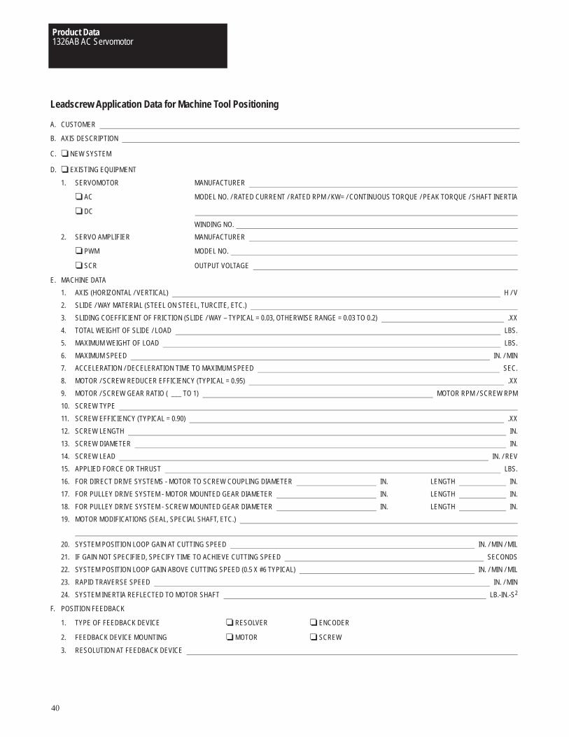
Product Data1326AB AC Servomotor
40
Leadscrew Application Data for Machine Tool Positioning
A. CUSTOMER
B. AXIS DESCRIPTION
C. ❏ NEW SYSTEM
D. ❏ EXISTING EQUIPMENT
1. SERVOMOTOR MANUFACTURER
❏ AC MODEL NO. / RATED CURRENT / RATED RPM / KW= / CONTINUOUS TORQUE / PEAK TORQUE / SHAFT INERTIA
❏ DC
WINDING NO.
2. SERVO AMPLIFIER MANUFACTURER
❏ PWM MODEL NO.
❏ SCR OUTPUT VOLTAGE
E. MACHINE DATA
1. AXIS (HORIZONTAL / VERTICAL) H / V
2. SLIDE / WAY MATERIAL (STEEL ON STEEL, TURCITE, ETC.)
3. SLIDING COEFFICIENT OF FRICTION (SLIDE / WAY – TYPICAL = 0.03, OTHERWISE RANGE = 0.03 TO 0.2) .XX
4. TOTAL WEIGHT OF SLIDE / LOAD LBS.
5. MAXIMUM WEIGHT OF LOAD LBS.
6. MAXIMUM SPEED IN. / MIN
7. ACCELERATION / DECELERATION TIME TO MAXIMUM SPEED SEC.
8. MOTOR / SCREW REDUCER EFFICIENCY (TYPICAL = 0.95) .XX
9. MOTOR / SCREW GEAR RATIO ( ___ TO 1) MOTOR RPM / SCREW RPM
10. SCREW TYPE
11. SCREW EFFICIENCY (TYPICAL = 0.90) .XX
12. SCREW LENGTH IN.
13. SCREW DIAMETER IN.
14. SCREW LEAD IN. / REV
15. APPLIED FORCE OR THRUST LBS.
16. FOR DIRECT DRIVE SYSTEMS - MOTOR TO SCREW COUPLING DIAMETER IN. LENGTH IN.
17. FOR PULLEY DRIVE SYSTEM - MOTOR MOUNTED GEAR DIAMETER IN. LENGTH IN.
18. FOR PULLEY DRIVE SYSTEM - SCREW MOUNTED GEAR DIAMETER IN. LENGTH IN.
19. MOTOR MODIFICATIONS (SEAL, SPECIAL SHAFT, ETC.)
20. SYSTEM POSITION LOOP GAIN AT CUTTING SPEED IN. / MIN / MIL
21. IF GAIN NOT SPECIFIED, SPECIFY TIME TO ACHIEVE CUTTING SPEED SECONDS
22. SYSTEM POSITION LOOP GAIN ABOVE CUTTING SPEED (0.5 X #6 TYPICAL) IN. / MIN / MIL
23. RAPID TRAVERSE SPEED IN. / MIN
24. SYSTEM INERTIA REFLECTED TO MOTOR SHAFT LB.-IN.-S2
F. POSITION FEEDBACK
1. TYPE OF FEEDBACK DEVICE ❏ RESOLVER ❏ ENCODER
2. FEEDBACK DEVICE MOUNTING ❏ MOTOR ❏ SCREW
3. RESOLUTION AT FEEDBACK DEVICE
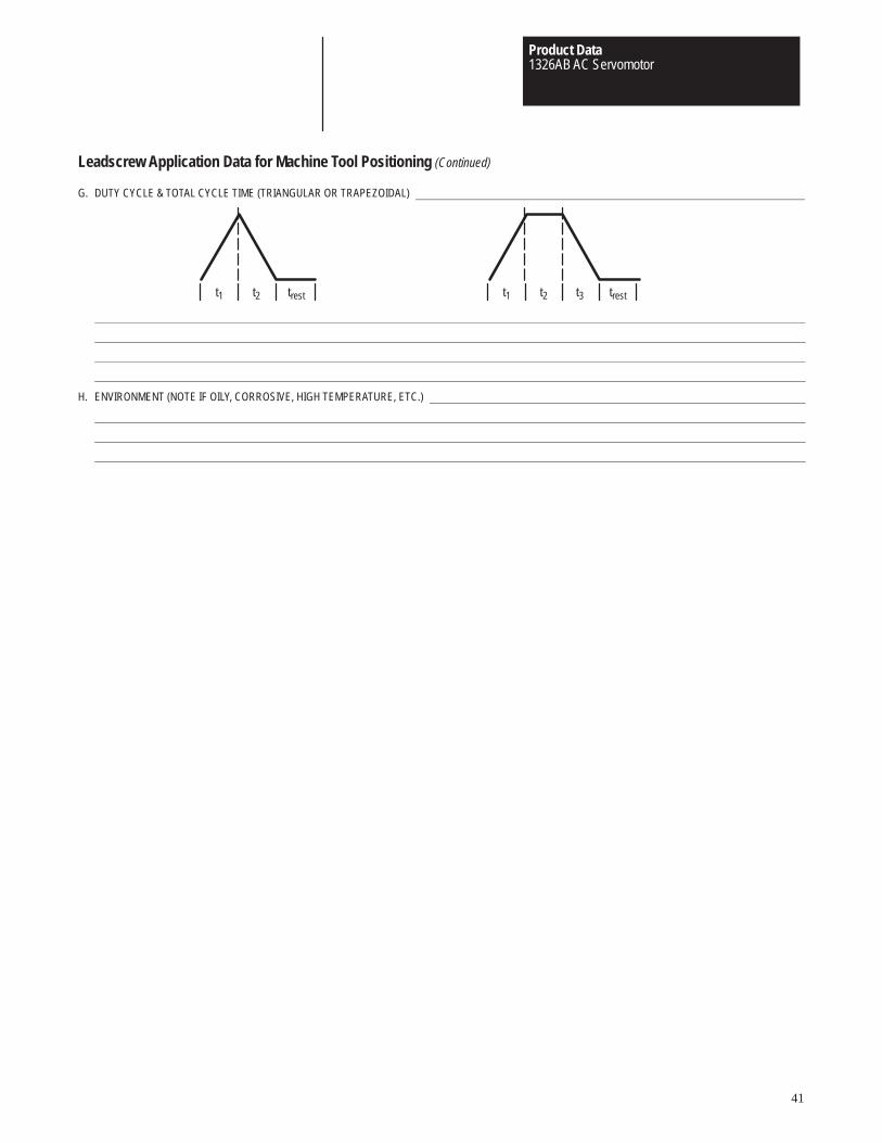
Product Data1326AB AC Servomotor
41
Leadscrew Application Data for Machine Tool Positioning (Continued)
G. DUTY CYCLE & TOTAL CYCLE TIME (TRIANGULAR OR TRAPEZOIDAL)
trestt3t2t1trestt2t1
H. ENVIRONMENT (NOTE IF OILY, CORROSIVE, HIGH TEMPERATURE, ETC.)
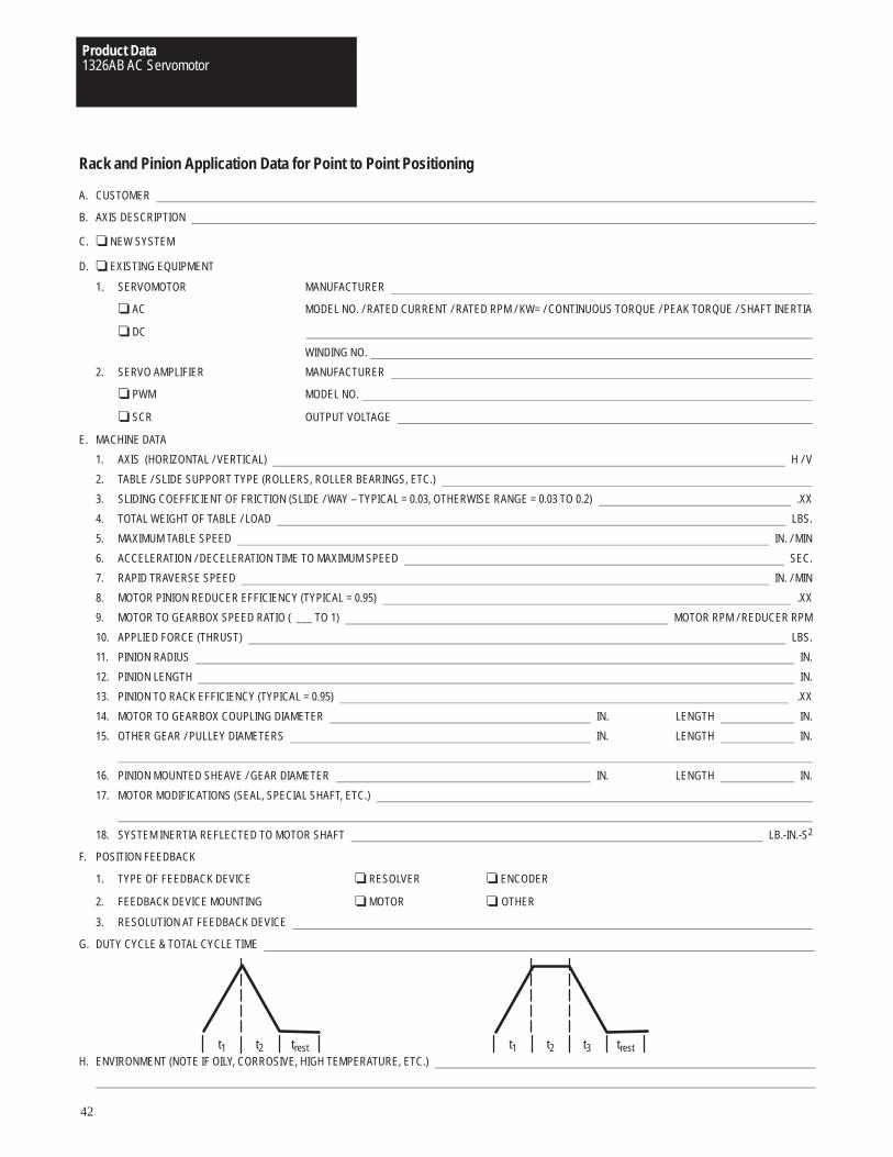
Product Data1326AB AC Servomotor
42
Rack and Pinion Application Data for Point to Point Positioning
A. CUSTOMER
B. AXIS DESCRIPTION
C. ❏ NEW SYSTEM
D. ❏ EXISTING EQUIPMENT
1. SERVOMOTOR MANUFACTURER
❏ AC MODEL NO. / RATED CURRENT / RATED RPM / KW= / CONTINUOUS TORQUE / PEAK TORQUE / SHAFT INERTIA
❏ DC
WINDING NO.
2. SERVO AMPLIFIER MANUFACTURER
❏ PWM MODEL NO.
❏ SCR OUTPUT VOLTAGE
E. MACHINE DATA
1. AXIS (HORIZONTAL / VERTICAL) H / V
2. TABLE / SLIDE SUPPORT TYPE (ROLLERS, ROLLER BEARINGS, ETC.)
3. SLIDING COEFFICIENT OF FRICTION (SLIDE / WAY – TYPICAL = 0.03, OTHERWISE RANGE = 0.03 TO 0.2) .XX
4. TOTAL WEIGHT OF TABLE / LOAD LBS.
5. MAXIMUM TABLE SPEED IN. / MIN
6. ACCELERATION / DECELERATION TIME TO MAXIMUM SPEED SEC.
7. RAPID TRAVERSE SPEED IN. / MIN
8. MOTOR PINION REDUCER EFFICIENCY (TYPICAL = 0.95) .XX
9. MOTOR TO GEARBOX SPEED RATIO ( ___ TO 1) MOTOR RPM / REDUCER RPM
10. APPLIED FORCE (THRUST) LBS.
11. PINION RADIUS IN.
12. PINION LENGTH IN.
13. PINION TO RACK EFFICIENCY (TYPICAL = 0.95) .XX
14. MOTOR TO GEARBOX COUPLING DIAMETER IN. LENGTH IN.
15. OTHER GEAR / PULLEY DIAMETERS IN. LENGTH IN.
16. PINION MOUNTED SHEAVE / GEAR DIAMETER IN. LENGTH IN.
17. MOTOR MODIFICATIONS (SEAL, SPECIAL SHAFT, ETC.)
18. SYSTEM INERTIA REFLECTED TO MOTOR SHAFT LB.-IN.-S2
F. POSITION FEEDBACK
1. TYPE OF FEEDBACK DEVICE ❏ RESOLVER ❏ ENCODER
2. FEEDBACK DEVICE MOUNTING ❏ MOTOR ❏ OTHER
3. RESOLUTION AT FEEDBACK DEVICE
G. DUTY CYCLE & TOTAL CYCLE TIME
trestt3t2t1trestt2t1H. ENVIRONMENT (NOTE IF OILY, CORROSIVE, HIGH TEMPERATURE, ETC.)
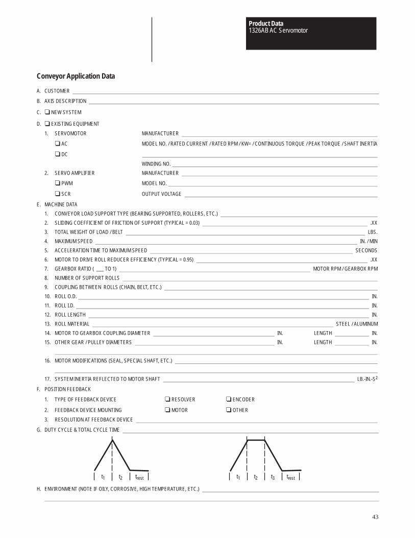
Product Data1326AB AC Servomotor
43
Conveyor Application Data
A. CUSTOMER
B. AXIS DESCRIPTION
C. ❏ NEW SYSTEM
D. ❏ EXISTING EQUIPMENT
1. SERVOMOTOR MANUFACTURER
❏ AC MODEL NO. / RATED CURRENT / RATED RPM / KW= / CONTINUOUS TORQUE / PEAK TORQUE / SHAFT INERTIA
❏ DC
WINDING NO.
2. SERVO AMPLIFIER MANUFACTURER
❏ PWM MODEL NO.
❏ SCR OUTPUT VOLTAGE
E. MACHINE DATA
1. CONVEYOR LOAD SUPPORT TYPE (BEARING SUPPORTED, ROLLERS, ETC.)
2. SLIDING COEFFICIENT OF FRICTION OF SUPPORT (TYPICAL = 0.03) .XX
3. TOTAL WEIGHT OF LOAD / BELT LBS.
4. MAXIMUM SPEED IN. / MIN
5. ACCELERATION TIME TO MAXIMUM SPEED SECONDS
6. MOTOR TO DRIVE ROLL REDUCER EFFICIENCY (TYPICAL = 0.95) .XX
7. GEARBOX RATIO ( ___ TO 1) MOTOR RPM / GEARBOX RPM
8. NUMBER OF SUPPORT ROLLS
9. COUPLING BETWEEN ROLLS (CHAIN, BELT, ETC.)
10. ROLL O.D. IN.
11. ROLL I.D. IN.
12. ROLL LENGTH IN.
13. ROLL MATERIAL STEEL / ALUMINUM
14. MOTOR TO GEARBOX COUPLING DIAMETER IN. LENGTH IN.
15. OTHER GEAR / PULLEY DIAMETERS IN. LENGTH IN.
16. MOTOR MODIFICATIONS (SEAL, SPECIAL SHAFT, ETC.)
17. SYSTEM INERTIA REFLECTED TO MOTOR SHAFT LB.-IN.-S2
F. POSITION FEEDBACK
1. TYPE OF FEEDBACK DEVICE ❏ RESOLVER ❏ ENCODER
2. FEEDBACK DEVICE MOUNTING ❏ MOTOR ❏ OTHER
3. RESOLUTION AT FEEDBACK DEVICE
G. DUTY CYCLE & TOTAL CYCLE TIME
trestt3t2t1trestt2t1
H. ENVIRONMENT (NOTE IF OILY, CORROSIVE, HIGH TEMPERATURE, ETC.)
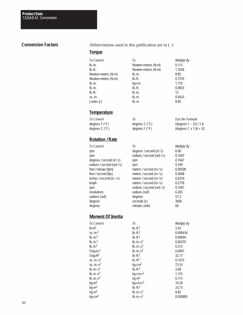
Product Data1326AB AC Servomotor
44
Conversion Factors Abbreviations used in this publication are in ( ).
Torque
To Convert To Multiply Bylb.-in. Newton-meters (N-m) 0.113lb.-ft. Newton-meters (N-m) 1.3558Newton-meters (N-m) lb.-in. 8.85Newton-meters (N-m) lb.-ft. 0.7376lb.-in. kg-cm 1.155lb.-in. lb.-ft. 0.0833lb.-ft. lb.-in. 12oz.-in. lb.-in. 0.0625Joules (J) lb.-in. 8.85
TemperatureTo Convert To Use the Formuladegrees F (°F) degrees C (°C) (degrees F – 32) / 1.8degrees C (°C) degrees F (°F) (degrees C x 1.8) + 32
Rotation / RateTo Convert To Multiply Byrpm degrees / second (d / s) 6.00rpm radians / second (rad / s) 0.1047degrees / second (d / s) rpm 0.1667radians / second (rad / s) rpm 9.549feet / minute (fpm) meters / second (m / s) 0.00508feet / second (fps) meters / second (m / s) 0.3048inches / second (in. / s) meters / second (m / s) 0.0254kmph meters / second (m / s) 0.2778rpm radians / second (rad / s) 0.1047revolutions radians (rad) 6.283radians (rad) degrees 57.3degrees seconds (s) 3600degrees minutes (min) 60
Moment Of InertiaTo Convert To Multiply ByN-m2 lb.-ft.2 2.42oz.-in.2 lb.-ft.2 0.000434lb.-in.2 lb.-ft.2 0.00694lb.-in.2 lb.-in.-s2 0.00259lb.-ft.2 lb.-in.-s2 0.373Slug-in.2 lb.-in.-s2 0.0847Slug-ft2 lb.-ft.2 32.17oz.-in.-s2 lb.-ft.2 0.1675oz.-in.-s2 kg-cm2 73.53lb.-in.-s2 lb.-ft.2 2.68lb.-in.-s2 kg-cm-s2 1.155lb.-in.-s2 kg-m2 0.113kg-m2 kg-cm-s2 10.20kg-m2 lb.-ft.2 23.73kg-m2 lb.-in.-s2 8.85kg-cm2 lb.-in.-s2 0.000885
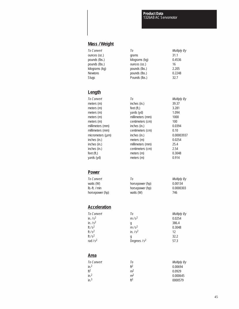
Product Data1326AB AC Servomotor
45
Mass / WeightTo Convert To Multiply Byounces (oz.) grams 31.1pounds (lbs.) kilograms (kg) 0.4536pounds (lbs.) ounces (oz.) 16kilograms (kg) pounds (lbs.) 2.205Newtons pounds (lbs.) 0.2248Slugs Pounds (lbs.) 32.7
LengthTo Convert To Multiply Bymeters (m) inches (in.) 39.37meters (m) feet (ft.) 3.281meters (m) yards (yd) 1.094meters (m) millimeters (mm) 1000meters (m) centimeters (cm) 100millimeters (mm) inches (in.) 0.0394millimeters (mm) centimeters (cm) 0.10micrometers (µm) inches (in.) 0.00003937inches (in.) meters (m) 0.0254inches (in.) millimeters (mm) 25.4inches (in.) centimeters (cm) 2.54feet (ft.) meters (m) 0.3048yards (yd) meters (m) 0.914
PowerTo Convert To Multiply Bywatts (W) horsepower (hp) 0.00134lb.-ft. / min horsepower (hp) 0.0000303horsepower (hp) watts (W) 746
AccelerationTo Convert To Multiply Byin. / s2 m / s2 0.0254in. / s2 g 386.4ft / s2 m / s2 0.3048ft / s2 in. / s2 12ft / s2 g 32.2rad / s2 Degrees / s2 57.3
AreaTo Convert To Multiply Byin.2 ft2 0.00694ft2 m2 0.0929in.2 m2 0.000645in.3 ft3 0000579

Product Data1326AB AC Servomotor
46

Product Data1326AB AC Servomotor
47
Publication 1326A-2.3 November, 1996Supersedes September, 1994 Copyright 1994 Allen-Bradley Company, Inc., a Rockwell International company Printed in USA